Effect of Geogrid Reinforcement Location in Paved Road Improvement Hossein Moayedi Department of Civil Engineering, University Putra Malaysia, Serdang, Selangor, Malaysia e-mail: [email protected] Sina Kazemian Research Scholar, Department of Civil Engineering, University Putra Malaysia, Serdang, Selangor, Malaysia e-mail: [email protected] Arun Prasad Post-Doctoral, Department of Civil Engineering, University Putra Malaysia, Serdang, Selangor, Malaysia e-mail: [email protected] Bujang B. K. Huat Professor, Department of Civil Engineering, University Putra Malaysia, Serdang, Selangor, Malaysia e-mail: [email protected] ABSTRACT A series of two-dimensional finite element simulations are carried out to evaluate the benefits of integrating a high modulus geogrid in a paved road. This paper describes the behavior of reinforced asphalt concrete (AC) pavement under plane strain conditions and subjected to monotonic loading. The results of improvement of paved track using geogrids are presented. Geogrid reinforcement into paved road in most cases will improve the performance of the transportation support. Analytical results for three different most possibilities of geogrid reinforcement in the paved road layers have been evaluated. The optimum position was decided based upon the tension stress absorption value, deformation reduce rate and tension cut-off point location. Three types of reinforcing model and one type of unreinforced model of paved road were selected. The results showed that tension stress absorption increases with shifting the geogrid towards the top of the pavement and attains the highest values when the geogrid is placed between asphalt layer and base layer in model. KEYWORDS: Paved road, Geogrid, Optimal location, Tension stress absorption. INTRODUCTION Geosynthetic materials have been successfully used to stabilize subgrade soils in road construction, which leads to improved performance of paved and unpaved roads. The research conducted so far indicates that the geogrids perform better as a reinforcing element. Reinforced soils are often treated as a

Welcome message from author
This document is posted to help you gain knowledge. Please leave a comment to let me know what you think about it! Share it to your friends and learn new things together.
Transcript
Effect of Geogrid Reinforcement
Location in Paved Road Improvement
Hossein Moayedi
Department of Civil Engineering, University Putra Malaysia,
Serdang, Selangor, Malaysia
e-mail: [email protected]
Sina Kazemian
Research Scholar, Department of Civil Engineering, University Putra Malaysia,
Serdang, Selangor, Malaysia
e-mail: [email protected]
Arun Prasad
Post-Doctoral, Department of Civil Engineering, University Putra Malaysia,
Serdang, Selangor, Malaysia
e-mail: [email protected]
Bujang B. K. Huat
Professor, Department of Civil Engineering, University Putra Malaysia, Serdang,
Selangor, Malaysia
e-mail: [email protected]
ABSTRACT A series of two-dimensional finite element simulations are carried out to evaluate the benefits of
integrating a high modulus geogrid in a paved road. This paper describes the behavior of reinforced
asphalt concrete (AC) pavement under plane strain conditions and subjected to monotonic loading. The
results of improvement of paved track using geogrids are presented. Geogrid reinforcement into paved
road in most cases will improve the performance of the transportation support. Analytical results for
three different most possibilities of geogrid reinforcement in the paved road layers have been
evaluated. The optimum position was decided based upon the tension stress absorption value,
deformation reduce rate and tension cut-off point location. Three types of reinforcing model and one
type of unreinforced model of paved road were selected. The results showed that tension stress
absorption increases with shifting the geogrid towards the top of the pavement and attains the highest
values when the geogrid is placed between asphalt layer and base layer in model.
KEYWORDS: Paved road, Geogrid, Optimal location, Tension stress absorption.
INTRODUCTION
Geosynthetic materials have been successfully used to stabilize subgrade soils in road construction,
which leads to improved performance of paved and unpaved roads. The research conducted so far
indicates that the geogrids perform better as a reinforcing element. Reinforced soils are often treated as a
Vol. 14 [2009], Bund. P 2
composite material, in which the reinforcement resists tensile stresses and interacts with soil through
friction. Geogrids can improve the performance of the subgrade soil through four mechanisms: prevention
of local shearing of the subgrade, improvement of load distribution through the base course, reduction or
reorientation of shear stresses on the subgrade, and tensioned membrane effect. Placed between the
subgrade and base course, or within the base course, the geosynthetic improves the performance of paved
roads. Reinforcement increases the bearing capacity of the subgrade, stiffens the base layer thereby
reducing normal stresses and changing the magnitude and orientation of shear stresses on the subgrade in
the loaded area, restricts lateral movement of the base course material and the subgrade soil, and can
provide tensioned membrane support where deep rutting occurs (Giroud et al., 1985).
One of the beneficial effects of geosynthetic reinforcement at the interface between base course and
subgrade soil is to carry the shear stresses induced by vehicular loads at the interface (Milligan and Love,
1984; Perkins, 1999). The interlocking between the geogrid and the base course aggregate results in
reduced lateral movement of the base course aggregate as a result, no outward shear stresses are
transmitted to the subgrade. At the same time, the bottom surface of the base course, with confined
aggregate striking through geogrid apertures, provides a rough surface that resists lateral movement by
the subgrade and increase the subgrade bearing capacity.
The geogrids have an elastic-plastic behavior so that they quickly react to applied loads with an
increase in the elastic modulus; in the case of short term impact loading, creep phenomenon does not
occur, therefore the whole tensile resistance of the geogrid can be mobilized. Further, geogrids allow an
increase of the dynamic dumping characteristics of the reinforced soil compared to unreinforced soil, both
through the energy that is directly absorbed by the geogrid itself and due to friction generated in the
dynamic stage (Carotti and Rimoldi, 1998).
Although there is a lot of information and experience with geosynthetic reinforcement of subgrade
soils, many pavement failures still occur. These failures may be due to the lack of understanding of how
these materials influence the engineering properties of subgrade soils and what is the optimum position of
reinforcement within a layer to derive maximum benefit.
Tension stress absorption of geogrid has changed surprisingly with change in position of the
reinforcement. Some researchers believe that geogrid should be placed near the load (Chan et al., 1989),
while others have found that it should be near the bottom or at mid-height (Broms, 1977). Giroud et al.
(1985) showed that the geogrids could improve the performance of subgrade soil through three
mechanisms, namely: confinement, improved load distribution through the base layer, and tensioned
membrane effect, which reduces stresses. For pavements constructed on soft subgrades, the reinforcement
should be placed at or near the bottom of the base.
Barksdale et al. (1989) utilized the results of a 2D finite element method to estimate the reduction in
base thickness for a stiff geosynthetic. Miura et al. (1990) carried out an isotropic linear elastic FE
analysis using 2D continuum elements to represent the HMA, base, subbase and subgrade layers. Dondi
(1994) performed a 3D FE analysis of a pavement structure using non-linear constitutive models for the
base and subgrade and a linear elastic model for the HMA and geogrid layers. Wathugala et al. (1996)
used the ABAQUS finite element program to explore the decrease in the rut depth as a result of placing
the geosynthetic membrane at the base–subgrade interface of a flexible pavement system. A series of
finite element simulations are carried out to evaluate the benefits of integrating a high modulus
geosynthetic into the pavement foundation. Three locations of the geosynthetic reinforcement are studied,
namely the base–asphalt concrete interface, the base–subgrade interface, and inside the base layer at a
Vol. 14 [2009], Bund. P 3
height of 1/3 of its thickness from the bottom. It is found that placing the geosynthetic reinforcement at
the base–asphalt concrete interface leads to the highest reduction of the fatigue strain (46–48%).
All these findings indicate that the position of geogrid in a layer is still a subject for research. The
present study was undertaken to investigate the optimum position of the geogrid in a layer of sand
subgrade soil. The geogrid was placed at different positions and effectiveness of reinforcement layer was
investigated through analytical modeling (Plaxis).
FINITE ELEMENT ANALYSIS
An axisymmetric analysis was carried out using Mohr-Coulomb’s criterion. The parameters required
for all the materials are for the calculations are presented in Table 1. The typical finite element mesh
consisted of 1765 nodes and 752 15-node triangular elements. Geogrid has been used as a strain
absorption interlayer system. Perkins (2001) demonstrated that in most of these analyses the geosynthetic
reinforcement membrane is considered as an isotropic elastic material. Interface elements have been used
at the interface of the geogrid. This will allow the relative deformation between the geogrid and gravel
and sand layers. Conventional kinematic boundary conditions are adopted, i.e., roller support on all four
vertical boundaries of the mesh and fixed support at the bottom of the mesh. Such boundary conditions
have been successfully used by Kuo et al. (1995). Iterative procedure is adopted for the solution to reduce
the normal out of balance force. This strain absorption interlayer system is a soft layer that is usually
placed at the bottom of an HMA overlay to absorb a large portion of the energy.
The unreinforced structure was modeled for a loading of 557 kPa having a radius of 200 mm (Yoder
and Witczak, 1975; Hansen et al., 1989). The analysis was carried out for drained condition without pore
water pressure changes. To simulate the stress dependency of the moduli, the structural layers were
divided into sub-layers with the same strength parameters, but different moduli. The axisymmetric
analysis was used to get a three dimensional stress distribution. The use of plain strain analysis, where the
loading would have been continuous line loading, would have given an overestimation of the stresses and
responses.
Table 1: Input parameters.
Material Asphalt Crushed Rock Crushed Gravel Sand
Thickness (mm) 50 200 250 1500
Elastic modulus (MPa) 5400 300-220-200 140-90 75
Poisson's ratio 0.3 0.35 0.35 0.35
Unit weight (kN/m3) 25 21.2 22 18
Cohesion (kPa) - 30 20 8
Friction angle (°) - 43 44 36
Dilatation angle (°) - 13 14 6
K0 1 0.32 0.3 0.42
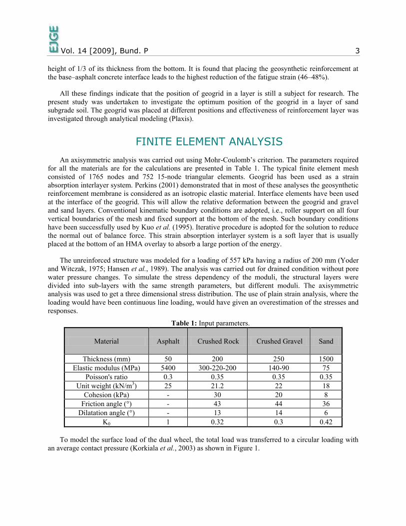
To model the surface load of the dual wheel, the total load was transferred to a circular loading with
an average contact pressure (Korkiala et al., 2003) as shown in Figure 1.
Vol. 14 [2009], Bund. P 4
Figure 1: Element surface load of the dual wheel.
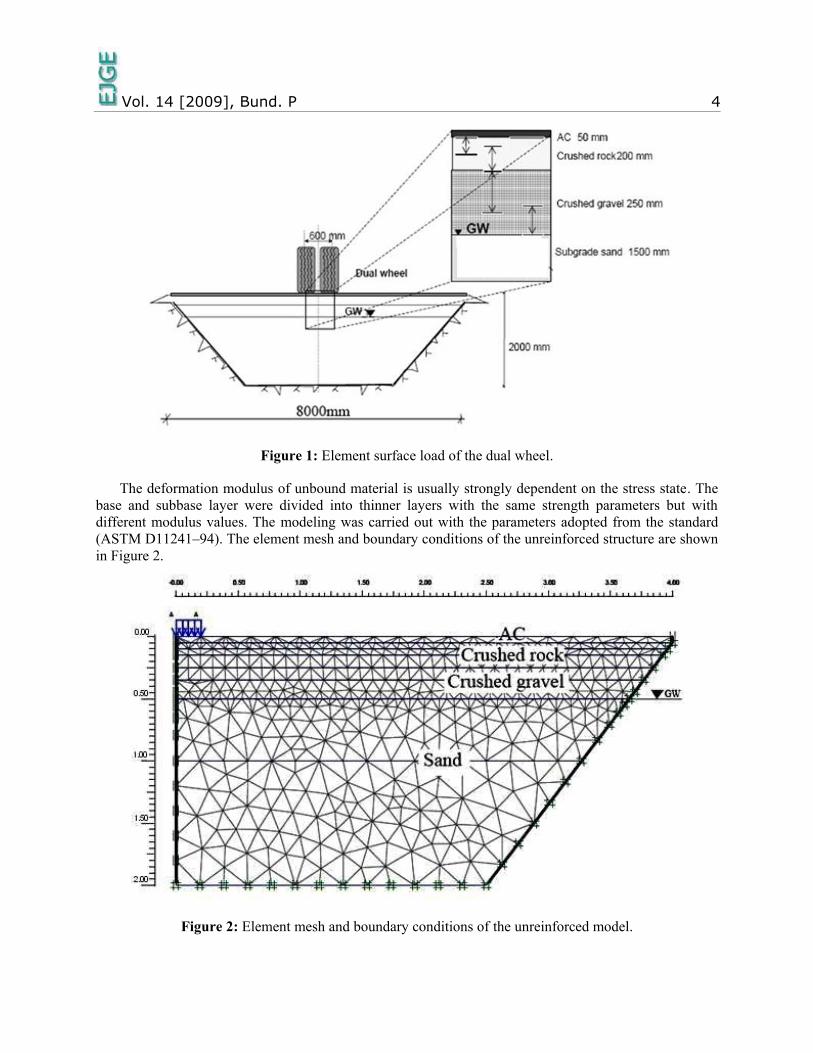
The deformation modulus of unbound material is usually strongly dependent on the stress state. The
base and subbase layer were divided into thinner layers with the same strength parameters but with
different modulus values. The modeling was carried out with the parameters adopted from the standard
(ASTM D11241–94). The element mesh and boundary conditions of the unreinforced structure are shown
in Figure 2.
Figure 2: Element mesh and boundary conditions of the unreinforced model.
Vol. 14 [2009], Bund. P 5
In these models, the attention was paid to the stress distributions and to the resilient deformations. All
analyses carried out were static. The dynamic analysis was not carried out because the dynamic module of
the Plaxis program is not suitable for modeling of traffic loading (Korkiala et al., 2003).
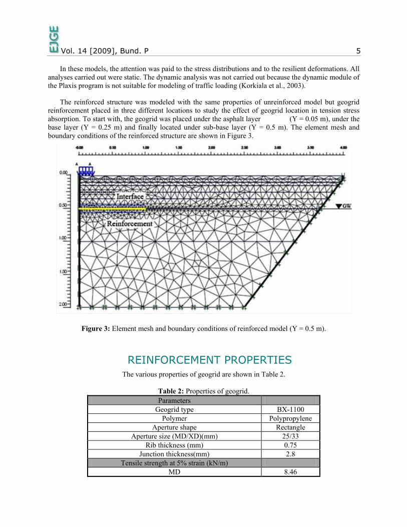
The reinforced structure was modeled with the same properties of unreinforced model but geogrid
reinforcement placed in three different locations to study the effect of geogrid location in tension stress
absorption. To start with, the geogrid was placed under the asphalt layer (Y = 0.05 m), under the
base layer (Y = 0.25 m) and finally located under sub-base layer (Y = 0.5 m). The element mesh and
boundary conditions of the reinforced structure are shown in Figure 3.
Figure 3: Element mesh and boundary conditions of reinforced model (Y = 0.5 m).
REINFORCEMENT PROPERTIES
The various properties of geogrid are shown in Table 2.
Table 2: Properties of geogrid.
Parameters
Geogrid type BX-1100
Polymer Polypropylene
Aperture shape Rectangle
Aperture size (MD/XD)(mm) 25/33
Rib thickness (mm) 0.75
Junction thickness(mm) 2.8
Tensile strength at 5% strain (kN/m)
MD 8.46
Vol. 14 [2009], Bund. P 6
XD 13.42
Initial modulus (kN/m2)
MD 226.4
XD 360.1
Long term allowable strength in crushed aggregate
MD N/A
MD = machine direction
XD = cross machine direction
RESULTS AND DISCUSSION
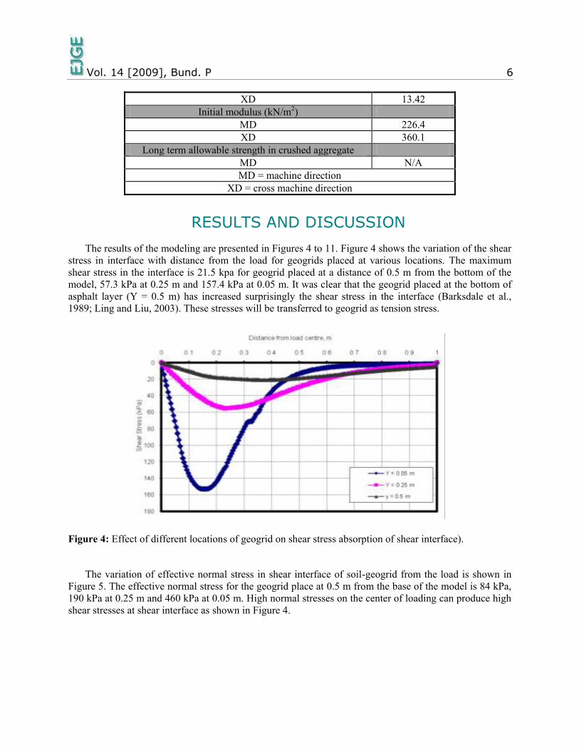
The results of the modeling are presented in Figures 4 to 11. Figure 4 shows the variation of the shear
stress in interface with distance from the load for geogrids placed at various locations. The maximum
shear stress in the interface is 21.5 kpa for geogrid placed at a distance of 0.5 m from the bottom of the
model, 57.3 kPa at 0.25 m and 157.4 kPa at 0.05 m. It was clear that the geogrid placed at the bottom of
asphalt layer (Y = 0.5 m) has increased surprisingly the shear stress in the interface (Barksdale et al.,
1989; Ling and Liu, 2003). These stresses will be transferred to geogrid as tension stress.
Figure 4: Effect of different locations of geogrid on shear stress absorption of shear interface).
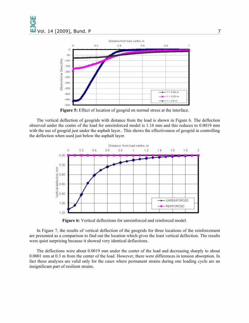
The variation of effective normal stress in shear interface of soil-geogrid from the load is shown in
Figure 5. The effective normal stress for the geogrid place at 0.5 m from the base of the model is 84 kPa,
190 kPa at 0.25 m and 460 kPa at 0.05 m. High normal stresses on the center of loading can produce high
shear stresses at shear interface as shown in Figure 4.
Vol. 14 [2009], Bund. P 7
Figure 5: Effect of location of geogrid on normal stress at the interface.
The vertical deflection of geogrids with distance from the load is shown in Figure 6. The deflection
observed under the centre of the load for unreinforced model is 1.16 mm and this reduces to 0.0019 mm
with the use of geogrid just under the asphalt layer.. This shows the effectiveness of geogrid in controlling
the deflection when used just below the asphalt layer.
Figure 6: Vertical deflections for unreinforced and reinforced model.
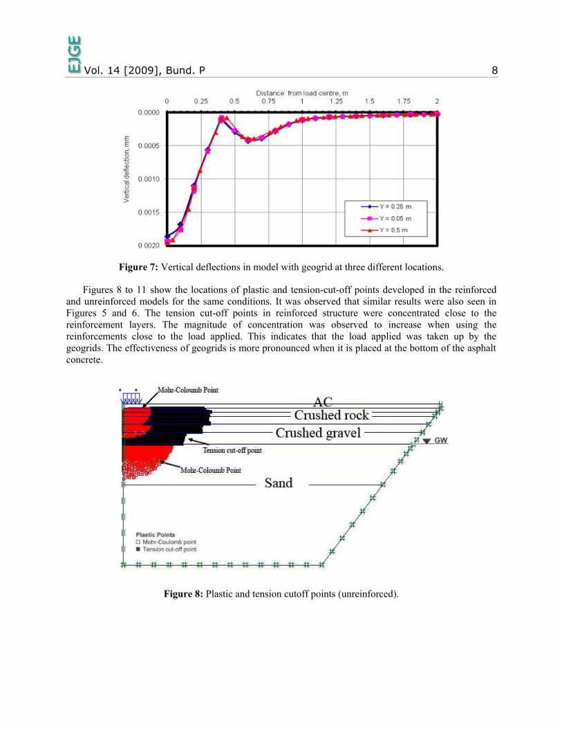
In Figure 7, the results of vertical deflection of the geogrids for three locations of the reinforcement
are presented as a comparison to find out the location which gives the least vertical deflection. The results
were quiet surprising because it showed very identical deflections.
The deflections were about 0.0019 mm under the center of the load and decreasing sharply to about
0.0001 mm at 0.3 m from the center of the load. However, there were differences in tension absorption. In
fact these analyses are valid only for the cases where permanent strains during one loading cycle are an
insignificant part of resilient strains.
Vol. 14 [2009], Bund. P 8
Figure 7: Vertical deflections in model with geogrid at three different locations.
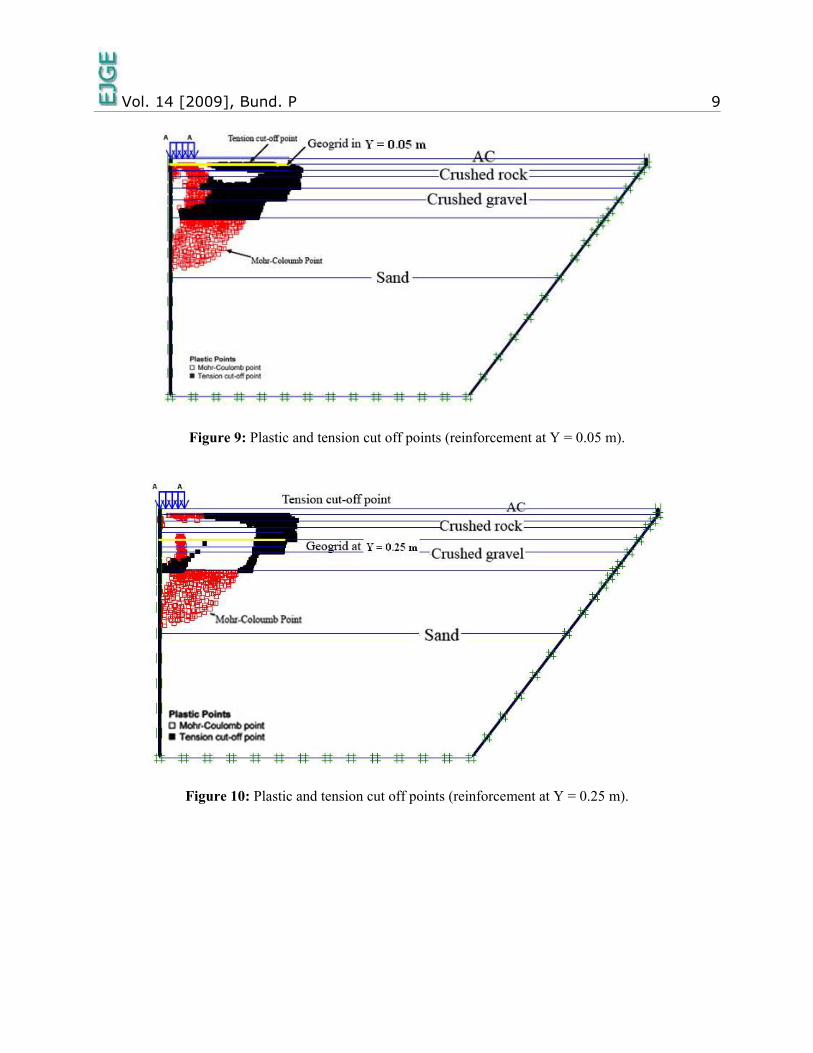
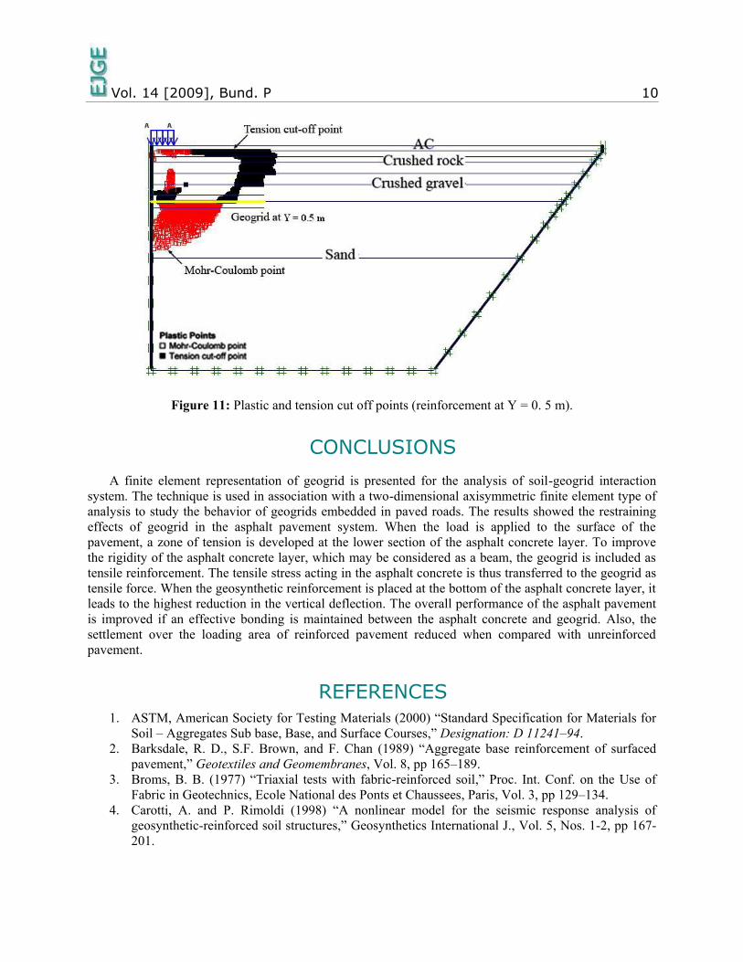
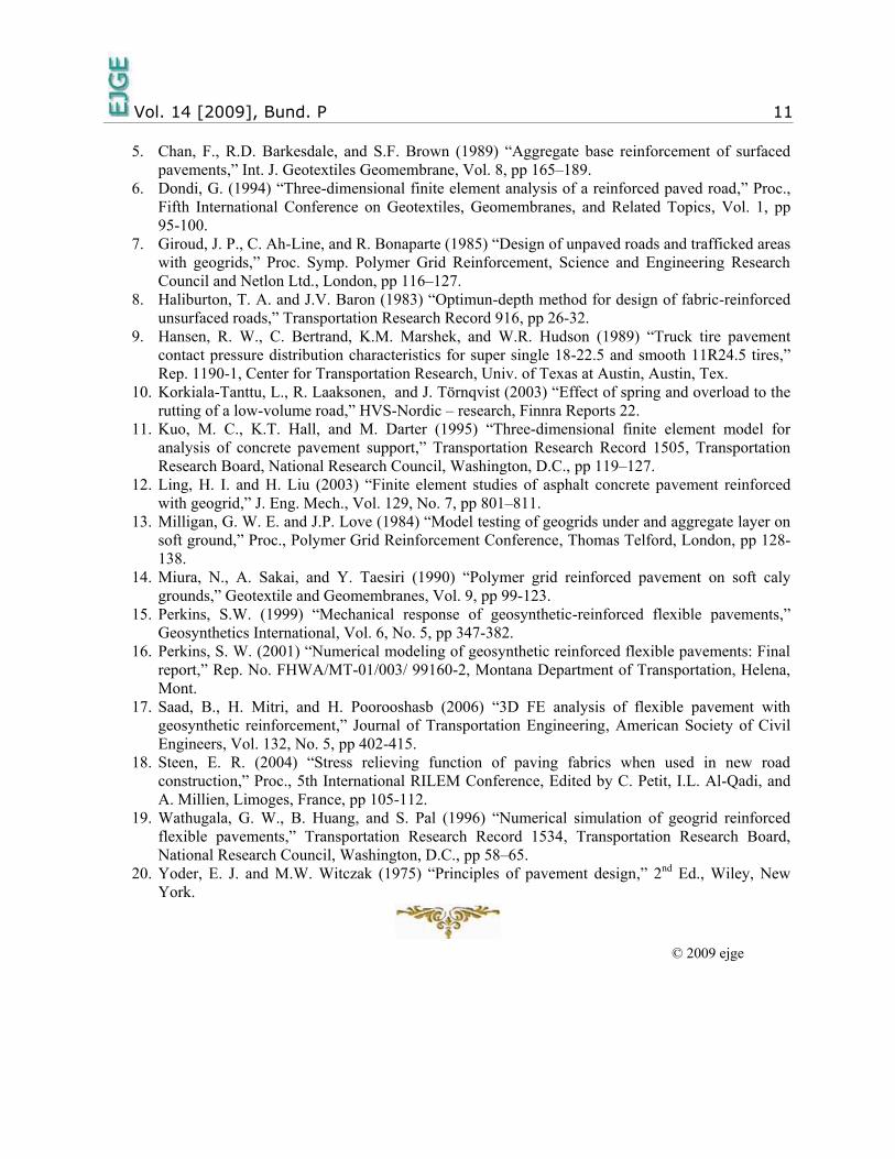
Figures 8 to 11 show the locations of plastic and tension-cut-off points developed in the reinforced
and unreinforced models for the same conditions. It was observed that similar results were also seen in
Figures 5 and 6. The tension cut-off points in reinforced structure were concentrated close to the
reinforcement layers. The magnitude of concentration was observed to increase when using the
reinforcements close to the load applied. This indicates that the load applied was taken up by the
geogrids. The effectiveness of geogrids is more pronounced when it is placed at the bottom of the asphalt
concrete.
Figure 8: Plastic and tension cutoff points (unreinforced).
Vol. 14 [2009], Bund. P 9
Figure 9: Plastic and tension cut off points (reinforcement at Y = 0.05 m).
Figure 10: Plastic and tension cut off points (reinforcement at Y = 0.25 m).
Vol. 14 [2009], Bund. P 10
Figure 11: Plastic and tension cut off points (reinforcement at Y = 0. 5 m).
CONCLUSIONS
A finite element representation of geogrid is presented for the analysis of soil-geogrid interaction
system. The technique is used in association with a two-dimensional axisymmetric finite element type of
analysis to study the behavior of geogrids embedded in paved roads. The results showed the restraining
effects of geogrid in the asphalt pavement system. When the load is applied to the surface of the
pavement, a zone of tension is developed at the lower section of the asphalt concrete layer. To improve
the rigidity of the asphalt concrete layer, which may be considered as a beam, the geogrid is included as
tensile reinforcement. The tensile stress acting in the asphalt concrete is thus transferred to the geogrid as
tensile force. When the geosynthetic reinforcement is placed at the bottom of the asphalt concrete layer, it
leads to the highest reduction in the vertical deflection. The overall performance of the asphalt pavement
is improved if an effective bonding is maintained between the asphalt concrete and geogrid. Also, the
settlement over the loading area of reinforced pavement reduced when compared with unreinforced
pavement.
REFERENCES
1. ASTM, American Society for Testing Materials (2000) “Standard Specification for Materials for
Soil – Aggregates Sub base, Base, and Surface Courses,” Designation: D 11241–94.
2. Barksdale, R. D., S.F. Brown, and F. Chan (1989) “Aggregate base reinforcement of surfaced
pavement,” Geotextiles and Geomembranes, Vol. 8, pp 165–189.
3. Broms, B. B. (1977) “Triaxial tests with fabric-reinforced soil,” Proc. Int. Conf. on the Use of
Fabric in Geotechnics, Ecole National des Ponts et Chaussees, Paris, Vol. 3, pp 129–134.
4. Carotti, A. and P. Rimoldi (1998) “A nonlinear model for the seismic response analysis of
geosynthetic-reinforced soil structures,” Geosynthetics International J., Vol. 5, Nos. 1-2, pp 167-
201.
Vol. 14 [2009], Bund. P 11
5. Chan, F., R.D. Barkesdale, and S.F. Brown (1989) “Aggregate base reinforcement of surfaced
pavements,” Int. J. Geotextiles Geomembrane, Vol. 8, pp 165–189.
6. Dondi, G. (1994) “Three-dimensional finite element analysis of a reinforced paved road,” Proc.,
Fifth International Conference on Geotextiles, Geomembranes, and Related Topics, Vol. 1, pp
95-100.
7. Giroud, J. P., C. Ah-Line, and R. Bonaparte (1985) “Design of unpaved roads and trafficked areas
with geogrids,” Proc. Symp. Polymer Grid Reinforcement, Science and Engineering Research
Council and Netlon Ltd., London, pp 116–127.
8. Haliburton, T. A. and J.V. Baron (1983) “Optimun-depth method for design of fabric-reinforced
unsurfaced roads,” Transportation Research Record 916, pp 26-32.
9. Hansen, R. W., C. Bertrand, K.M. Marshek, and W.R. Hudson (1989) “Truck tire pavement
contact pressure distribution characteristics for super single 18-22.5 and smooth 11R24.5 tires,”
Rep. 1190-1, Center for Transportation Research, Univ. of Texas at Austin, Austin, Tex.
10. Korkiala-Tanttu, L., R. Laaksonen, and J. Törnqvist (2003) “Effect of spring and overload to the
rutting of a low-volume road,” HVS-Nordic – research, Finnra Reports 22.
11. Kuo, M. C., K.T. Hall, and M. Darter (1995) “Three-dimensional finite element model for
analysis of concrete pavement support,” Transportation Research Record 1505, Transportation
Research Board, National Research Council, Washington, D.C., pp 119–127.
12. Ling, H. I. and H. Liu (2003) “Finite element studies of asphalt concrete pavement reinforced
with geogrid,” J. Eng. Mech., Vol. 129, No. 7, pp 801–811.
13. Milligan, G. W. E. and J.P. Love (1984) “Model testing of geogrids under and aggregate layer on
soft ground,” Proc., Polymer Grid Reinforcement Conference, Thomas Telford, London, pp 128-
138.
14. Miura, N., A. Sakai, and Y. Taesiri (1990) “Polymer grid reinforced pavement on soft caly
grounds,” Geotextile and Geomembranes, Vol. 9, pp 99-123.
15. Perkins, S.W. (1999) “Mechanical response of geosynthetic-reinforced flexible pavements,”
Geosynthetics International, Vol. 6, No. 5, pp 347-382.
16. Perkins, S. W. (2001) “Numerical modeling of geosynthetic reinforced flexible pavements: Final
report,” Rep. No. FHWA/MT-01/003/ 99160-2, Montana Department of Transportation, Helena,
Mont.
17. Saad, B., H. Mitri, and H. Poorooshasb (2006) “3D FE analysis of flexible pavement with
geosynthetic reinforcement,” Journal of Transportation Engineering, American Society of Civil
Engineers, Vol. 132, No. 5, pp 402-415.
18. Steen, E. R. (2004) “Stress relieving function of paving fabrics when used in new road
construction,” Proc., 5th International RILEM Conference, Edited by C. Petit, I.L. Al-Qadi, and
A. Millien, Limoges, France, pp 105-112.
19. Wathugala, G. W., B. Huang, and S. Pal (1996) “Numerical simulation of geogrid reinforced
flexible pavements,” Transportation Research Record 1534, Transportation Research Board,
National Research Council, Washington, D.C., pp 58–65.
20. Yoder, E. J. and M.W. Witczak (1975) “Principles of pavement design,” 2nd Ed., Wiley, New
York.
© 2009 ejge
Related Documents