University of Calgary PRISM: University of Calgary's Digital Repository Graduate Studies The Vault: Electronic Theses and Dissertations 2016-02-04 Effect of Downhole Vibration on Coiled Tubing Reach in Horizontal Intervention Yekta Ganjeh, Kaveh Yekta Ganjeh, K. (2016). Effect of Downhole Vibration on Coiled Tubing Reach in Horizontal Intervention (Unpublished master's thesis). University of Calgary, Calgary, AB. doi:10.11575/PRISM/25797 http://hdl.handle.net/11023/2841 master thesis University of Calgary graduate students retain copyright ownership and moral rights for their thesis. You may use this material in any way that is permitted by the Copyright Act or through licensing that has been assigned to the document. For uses that are not allowable under copyright legislation or licensing, you are required to seek permission. Downloaded from PRISM: https://prism.ucalgary.ca

Welcome message from author
This document is posted to help you gain knowledge. Please leave a comment to let me know what you think about it! Share it to your friends and learn new things together.
Transcript

University of Calgary
PRISM: University of Calgary's Digital Repository
Graduate Studies The Vault: Electronic Theses and Dissertations
2016-02-04
Effect of Downhole Vibration on Coiled Tubing Reach
in Horizontal Intervention
Yekta Ganjeh, Kaveh
Yekta Ganjeh, K. (2016). Effect of Downhole Vibration on Coiled Tubing Reach in Horizontal
Intervention (Unpublished master's thesis). University of Calgary, Calgary, AB.
doi:10.11575/PRISM/25797
http://hdl.handle.net/11023/2841
master thesis
University of Calgary graduate students retain copyright ownership and moral rights for their
thesis. You may use this material in any way that is permitted by the Copyright Act or through
licensing that has been assigned to the document. For uses that are not allowable under
copyright legislation or licensing, you are required to seek permission.
Downloaded from PRISM: https://prism.ucalgary.ca

UNIVERSITY OF CALGARY
Effect of Downhole Vibration on Coiled Tubing Reach in Horizontal Intervention
by
Kaveh Yekta Ganjeh
A THESIS
SUBMITTED TO THE FACULTY OF GRADUATE STUDIES
IN PARTIAL FULFILMENT OF THE REQUIREMENTS FOR THE
DEGREE OF MASTER OF SCIENCE
GRADUATE PROGRAM IN MECHANICAL ENGINEERING
CALGARY, ALBERTA
FEBRUARY, 2016
© Kaveh Yekta Ganjeh 2016
ii
Abstract
Technological advances enabled horizontal drilling to expose deeper and longer
horizontal lateral sections, thereby maximizing producing zones in reservoirs. The use of Coiled
Tubing (CT) to perform different types of well intervention operations is limited by the
maximum depth in the horizontal section. One of the most effective remedies is the application
of downhole vibration. This thesis proposes a method to describe the effect of vibrations to
improve load transfer for a CT with a straight, a sinusoidally buckled and a helically buckled
configuration. In order to capture the effect of vibration on the reduction of friction, the concept
of apparent friction factor is introduced for all three types of section. The proposed approach is
validated against published experimental data, for both the non-vibrating and the vibrating cases.
Full wellbore axial force transfer and slack-off weight models are developed to simulate the
effect of downhole vibration to enhance CT reach.

iii
Acknowledgements
I would like to thank Dr. Les Sudak for having been my supervisor and for his support
through these years.
I would like to express my most wholehearted thanks to Dr. Salvatore Federico for his
supervision, unlimited support and friendship throughout this work. Dr. Federico was my initial
supervisor and later, for bureaucratic reasons, became my co-supervisor. He provided me with
his support and guidance in every step of this work, and especially in the last few months prior to
my graduation. Dr. Federico provided me with a lot of technical feedback on my research project
and helped me to prepare a professionally written thesis. Whenever there was a challenge for me
to face during this work, Dr. Federico was there to offer his advice and support.
I would like to thank Dr. Marcelo Epstein for recommending me to Dr. Federico to start
my MSc program under Dr. Federico’s supervision as well as for serving in my examining
committee. His questions during the exam and his support after the exam undoubtedly brought
me confidence that I had done the job right.
I would like to thank Dr. Hussein Hejazi for serving in my examining committee, for his
careful reading of my work, and for his valuable feedback during the examination.
I would like to thank Dr. Meera Singh for serving in my examining committee.

iv
Dedication
To my lovely wife, Azadeh, for her constant and unconditional support, patience,
encouragement and sacrifice throughout this work. Without her, I would not have been able to
finish this work.
To our beautiful and lovely little girl, Elena, who is the source of love and happiness in
our life.
To my late mom and dad, who are not with us to see their son’s achievement. God bless
them.

v
Table of Contents
Abstract ............................................................................................................................... ii Acknowledgements ............................................................................................................ iii Dedication .......................................................................................................................... iv Table of Contents .................................................................................................................v List of Figures and Illustrations ........................................................................................ vii Chapter 1. Introduction ...............................................................................................1 Chapter 2. Literature Review ......................................................................................5 Chapter 3. Coiled Tubing Services ...........................................................................17
3.1. Coiled Tubing Equipment .......................................................................19 3.1.1. Coiled Tubing String .................................................................19 3.1.2. Coiled Tubing power pack unit .................................................20 3.1.3. Coiled Tubing Control Cabin ....................................................21 3.1.4. Coiled Tubing Reel ...................................................................23 3.1.5. Coiled Tubing Injector Head and Gooseneck ...........................25 3.1.6. Stripper (Stuffing Box) .............................................................27 3.1.7. Blowout Preventer (BOP) .........................................................28 3.1.8. Downhole Tools ........................................................................30
3.2. Coiled Tubing Applications ....................................................................32 3.2.1. Coiled Tubing Cleanout ............................................................32 3.2.2. Coiled Tubing Milling ...............................................................33 3.2.3. Coiled Tubing Logging .............................................................33 3.2.4. Coiled Tubing Matrix Stimulation (Acidizing) .........................34 3.2.5. Coiled Tubing Drilling ..............................................................34 3.2.6. Coiled Tubing Fracturing ..........................................................35 3.2.7. Coiled Tubing Cementing .........................................................35 3.2.8. Coiled Tubing Fishing ...............................................................36 3.2.9. Coiled Tubing Nitrogen Kick off ..............................................36 3.2.10. Application of Coiled Tubing Equipped with Optical Fibers .37
3.3. Job Design Considerations for Coiled Tubing Services .........................37
3.4. Downhole Vibrating Tool .......................................................................38 Chapter 4. Theoretical Background ..........................................................................41

vi
Chapter 5. Modeling .................................................................................................61
5.1. Modeling vs Published Experimental Data .............................................61
5.2. Full Wellbore Modeling ..........................................................................68 Chapter 6. Summary and Recommendations ............................................................83 References ..........................................................................................................................85 Appendix A Force-Pitch Relationship .........................................................................93 Appendix B Sinusoidal Buckling Load .......................................................................96 Appendix C Helical Buckling Load ............................................................................98

vii
List of Figures and Illustrations
Figure 3-1: Coiled Tubing equipment rig-up configuration ......................................................... 18
Figure 3-2: Power pack skid unit .................................................................................................. 21
Figure 3-3: Coiled Tubing control unit ......................................................................................... 23
Figure 3-4: Coiled Tubing Reel unit ............................................................................................. 25
Figure 3-5: Coiled Tubing injector head and Gooseneck ............................................................. 27
Figure 3-6: Coiled Tubing Stripper (Stuffing Box) ...................................................................... 28
Figure 3-7: Coiled Tubing Blowout Preventer (BOP) .................................................................. 30
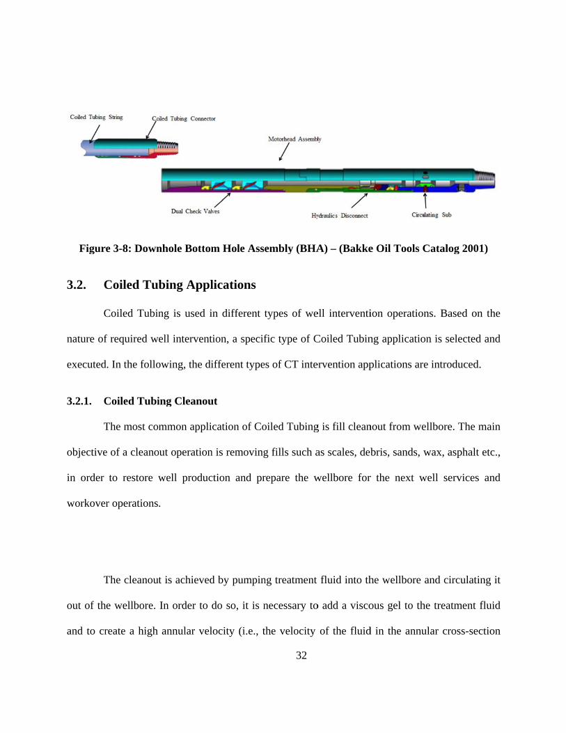
Figure 3-8: Downhole Bottom Hole Assembly (BHA) – (Bakke Oil Tools Catalog 2001)......... 32
Figure 3-9: Downhole vibrating tool (Agitator) ........................................................................... 40
Figure 4-1:Buckling of string in wellbore .................................................................................... 42
Figure 4-2:Helix geometry and pitch of buckled string ................................................................ 44
Figure 4-3: Configuration of string in wellbore ............................................................................ 47
Figure 4-4: Sinusoidal buckled string in horizontal wellbore ....................................................... 51
Figure 4-5: Helical buckled string in horizontal wellbore ............................................................ 52
Figure 4-6: Force balanced in horizontal wellbore ....................................................................... 53
Figure 4-7: Lock-up condition graph ............................................................................................ 59
Figure 5-1: Experimental data extracted from Wu and Juvkam-Wold (1993c) ........................... 62
Figure 5-3: Experimental data extracted from Newman et al. ...................................................... 64
Figure 5-4: Axial loading vs Experimental data for non-vibrating case ....................................... 65
Figure 5-7: Axial Loading Models for Vibrating and Non-Vibrating Cases ................................ 68
Figure 5-10: Wellbore survey in 2D ............................................................................................. 71

viii
Figure 5-11: Wellbore Completions ............................................................................................. 72
Figure 5-14: Slack off weight calculation for vertical and curved (heel) sections ....................... 75
Figure 5-15: Slack off weight calculation for vertical, curved and horizontal sections ............... 76
Figure 5-16: Axial Compressive force for CT string at depth of 4584.91 mMD ......................... 77
Figure 5-17: Slack off weight graph for CT string at depth of 4584.91 mMD ............................. 78
Figure 5-18: Axial Compressive force for CT string at depth of 4665.92 mMD ......................... 79
Figure 5-19: Slack off weight graph for CT string at depth of 4665.92 mMD ............................. 80
Figure 5-20: Downhole Vibration Application - Axial Compressive force at 4665.92 mMD ..... 81
Figure 5-21: Downhole Vibration Application – Slack off weight at 4665.92 mMD .................. 82

1
Chapter 1. Introduction
Coiled Tubing (CT) is a very long and continuously milled pipe which is manufactured
in different sizes and lengths. Coiled Tubing pipes, along with different surface equipment and
downhole tools, are used for intervention operations in the oil and gas industry. Coiled Tubing
surface equipment consists of power pack, control cabin, reel (spool), Gooseneck (arch guide),
injector, stripper and blowout preventer (BOP). Selected sets of downhole tools suitable for
intervention purpose are conveyed with the Coiled Tubing string. Coiled Tubing services is the
collective name of the application of Coiled Tubing string, surface equipment and downhole
tools to perform different well intervention and well serving operations. Coiled Tubing has
different applications such as CT cleanout, milling, logging, matrix stimulation (acidizing),
drilling, fracturing cementing, fishing and nitrogen kick-off. The possibility of deployment in
horizontal wells and of pumping fluid/nitrogen are among the main advantages of Coiled Tubing
services compare to other intervention methods such as Wire-line and Slick-line services.
The main challenges in horizontal intervention are reaching to desired depth and
providing proper weight on bit (WOB), intended as the force to be exerted on downhole tool to
perform the desired operation. The friction force between the wellbore and the CT string
increases as the horizontal section gets more extended. An increase in this wellbore drag causes
some sections of the CT string to buckle into a sinusoidal configuration and subsequently into a
helical configuration. Once the CT has buckled into the helical shape, the wellbore friction
increases significantly and the CT cannot be pushed farther into the wellbore causing to “lock-

2
up”. One of the solutions to this problem is the introduction of downhole vibration. The
downhole vibrating tool is a component of the bottomhole assembly (BHA) that is used to create
axial vibration at the bottom section of the CT string. The downhole vibrating tool provides axial
vibration as a result of the fluid pumped into the tool through the CT. Downhole vibration
enables CT string to extend its reach in a wellbore that was initially restricted due to the lock-up
condition.
The buckling phenomenon in a drilling string and in a CT string has been studied
extensively by various researchers. Early studies focused on buckling in various completion
configurations in the wellbore. Several studies have aimed at understanding sinusoidal and
helical buckling effects in a drill string and in a CT string.
Many different aspects of buckling in drilling and well intervention have been studied
both experimentally and theoretically. For instance, models have been developed for the force
transfer relationship in vertical, deviated and horizontal wellbore, the effect of friction, variable
pitch, wellbore curvature, lock-up condition, contact force due to sinusoidal/helical buckling,
torque and shear. Soft string modeling is used to calculate the axial force in the CT string and
stiff string (beam-column) modeling is used to model the long BHA used in drilling applications.
On the contrary, there are not as many studies regarding the effect of downhole vibration
in CT application. The proprietary nature of such modeling could be one the reasons: the
companies that develop them do not reveal most details.
Newman et al. (2007a, 2007b and 2009) conducted surface tests in order to investigate
the effect of vibration and rotation on reducing the friction. It was mentioned that a model was

3
developed to analyze the effect of vibration on load transfer but the details of the model were not
revealed in their studies.
In order to model the reach of the CT string to a certain depth using a downhole
vibration tool, it is required to understand the effect of vibration on the enhancement of load
transfer from the surface to downhole and on the reduction of wellbore friction drag.
The present study proposes a modeling method to describe the effect of vibrations on
improving load transfer using straight, sinusoidal and helical buckling configurations.
Additionally, the study uses an application of apparent friction factor concept for all three
sections as a means to capture the effect of vibration to reduce friction. The proposed approach is
validated against published experimental data, for both the non-vibrating and the vibrating cases.
Full wellbore axial force transfer and slack-off weight models are developed in order to simulate
the effect of downhole vibration to enhance CT reach. Axial load transfer simulations are run for
the entire wellbore with and without the application of downhole vibrating tool. The
improvement in CT reach achieved by the application of downhole tools is verified by means of
numerical simulations.
This thesis is structured as follows. Chapter 2 provides a summary of the research about
different aspects of the buckling phenomenon and the effect of downhole vibration in the oil and
gas industry. Chapter 3 consists of four sections: Section 3.1 (Coiled Tubing Equipment) reviews
different components which are used in every CT operation and explains their function;
Section 3.2 (Coiled Tubing Application) explains different services which are used in
intervention operations; Section 3.3 (Job Design Considerations) outlines the requirements for

4
modeling an intervention job using CT services and the limitations arising at the modeling stage;
Section 3.4 (Downhole Vibrating Tool) reviews the different components and function of this
type of downhole tool. Chapter 4 reports published criteria for the buckling of CT string and the
use of energy methods to derive the relationship for sinusoidal and helical buckling. The axial
load distribution force relationship for vertical, curved and horizontal section of wellbore are
derived. The governing differential equations that are used to calculate the axial load force for
different sections of well are also presented. Chapter 5 is the work developed in this thesis, and
presents experimental tests and data from the literature and proposes a modeling approach to
explain the effect of downhole vibration to enhance load transfer using such data. A full wellbore
axial load distribution and slack off weight (lock-up condition) simulations are presented for
both non-vibrating and vibrating cases. Finally, Chapter 6 presents a summary of the results of
this thesis and outlines the possible future work.
5
Chapter 2. Literature Review
The buckling of a pipe in a wellbore has been studied for many years in the oil and gas
industry. In the early stages of this study, the focus was on drilling and completions (packers)
applications and, subsequently, on coiled tubing as well as intervention applications. Lubinski
(1950) studied the theory of buckling of rotary drill string in one plane. Lubinski et al. (1962)
presented the effect of helical buckling in packer-tubing system for several different
configurations. The pitch-force relationship for helically buckled tubing was derived, based on
energy methods, as (see Appendix A.)
2
2
8 EIF
p
,
( 2.1)
where F is compressive force along the axis of the helix, E is Young’s modulus, I is moment
of inertia of the cross section and p is pitch of the helix. Paslay and Bogy (1964) studied the
stability of the rod in a constrained cylindrical geometry by using energy methods. In their
approach, it was assumed that rod maintained constant contact with the circular wellbore, that the
angular displacement at the boundary was zero and that no change occurred in the curvature of
the tubing. The total potential energy of the system was calculated and minimized in order to
find the critical buckling load ( critF ).
Walker and Friedman (1977) presented a three-dimensional force and deflection model
for studying the drill string. By using the general theory of bending and twisting of rods (e.g.,
Love, 1944), they presented a mathematical model to calculate force/moment and deflection for

6
the bottom-hole assembly in a wellbore. Their formulation was based on other researchers’ work
in beam equilibrium approach, aimed at describing buckling phenomena in a wellbore.
Hammerlindl (1980) extended the study on force transmission in packer/tubing system started by
Lubinski et al. (1962), and examined the displacements and forces in two-packer configurations
for several cases. Mitchell (1982) studied helical buckling in a packer-tubing configuration by
using equilibrium equations, and based his study on the drill string deflection analysis presented
by Walker and Friedman (1977).
Mitchell (1982) presented a formulation to evaluate stress and deformation at the packer,
and considered the influence of the packer and the weightlessness of the tubing. Dawson and
Paslay (1984) determined the conditions for the stability of the drill pipe in an inclined well.
They used the stability conditions for a circular rod inside a horizontal wellbore, which had been
studied by Paslay and Bogy (1964), and obtained the relation
2 2 42
2 2 4
1
1 1 2crit
L AgF EI n
L n EIr
, ( 2.2)
where Fcrit is the critical axial load to initiate buckling, is the Poisson’s ratio, E is Young’s
modulus, I is cross-section moment of inertia, n is order of buckling, L is length of the drill
pipe, is mass density of the pipe, A is the cross-section of the pipe, g is the gravitational
force per unit mass, and r is the radial clearance between pipe and wellbore. The formula is for
horizontal applications only. Dawson and Paslay (1984) generalized the stability criteria from the
horizontal to the inclined wellbore by considering the component of the weight per unit length in

7
the inclined wellbore ( sinAg ). The stability criterion for the inclined wellbore was thus
obtained as
2 42
2 2 4
sincrit
L AgF EI n
L n EIr
.
( 2.3)
The minimum value of critF for an inclined wellbore with respect to n resulted in
sinusoidal (critical) buckling load as follows (see Appendix B. Equation B-9)
:
sin2crit
EI AgF
r
,
( 2.4)
where is inclination angle. Dawson and Paslay (1984) also showed that, in a highly inclined
hole, the drill pipe is capable of carrying high compressive loads without buckling.
Cheatham and Pattillo (1984) presented a new force-pitch relationship in the extension of
the work by Lubinski et al. (1962) for a straight weightless column. They studied the loading and
unloading scenario in terms of force-pitch relationship. Mitchell (1986a) used a numerical
technique to solve the buckling problem in a tubing/packer configuration and introduced the
novel concept of "neutral point" based on the contact force. Mitchell (1986b) also studied the
effect of friction in helical buckling phenomena in a vertical wellbore. He studied two simple
cases of tubing moving upward and downward: considering the effect of friction, he proposed an
axial load distribution for a vertical wellbore with a helically buckled pipe. Sorenson and
Cheatham (1986) studied the effect of boundary conditions on the post-buckling configuration of
a pipe in a confined circular cylinder, including the contact between the pipe and the wellbore

8
constraint. A semi-analytical solution for the helical buckling problem was proposed by Kwon
(1988), who considered the weight of the pipe and a variable pitch, using a beam-column method
(rather than an energy method). The solution proposed by Kwon (1988) was applied to a tapered
tubing configuration and solved numerically.
Mitchell (1988) introduced a new approach to solve the helical buckling problem for a
tubing/packer completion in a vertical wellbore. He considered the boundary conditions on the
packer, a variable helix pitch and tapered completion configurations. Chen et al. (1989) studied
the buckling phenomenon in casing/tubing configurations and presented buckling force criteria
for sinusoidal and helical buckling in a horizontal wellbore. They derived a sinusoidal buckling
load similar to that by Dawson and Paslay (1984) and determined that an increase in the
compressive axial load causes the tubing to have a transition from sinusoidal to helical buckling.
Chen et al. (1989) applied energy methods to calculate the required criteria for the helically
buckling force. Minimization the total energy with respect to the number of full waves in a long
horizontal pipe resulted in the expression (see Appendix C for details)
* 2 2EIw
Fr
, ( 2.5)
where F *(also known as helF ) is helical buckling load and w is weight per unit length of the
pipe. Chen et al. (1989) also conducted experiments in order to verify the validity of their
proposed relationship. Zhang (1989) considered variable pitch in the study of a helically buckled
drill string in a vertical wellbore: the variable helix pitch was deemed to be beneficial to the

9
calculation of the drill string configuration. He assumed that the friction force is reduced and
does not have any effect on the stability of the drill string because of axial vibration.
In a different publication, Chen et al. (1990) again presented sinusoidal and helical
buckling criteria for a pipe in a horizontal wellbore and performed experiment to support their
findings. Chen and Adnan (1993) studied the effect of gravity on helical buckling in an inclined
wellbore, by means of energy methods. Wu and Juvkam-Wold (1993a, 1993b) improved the
calculation of the helical buckling load by implementing a linearly increasing axial force under
buckling, instead of a constant one. The new helical buckling load Fhel , based on energy
methods, is
sin2 2 2 1hel
EIwF
r
.
( 2.6)
Wu and Juvkam-Wold (1993a, 1993b) also performed experimental tests to verify their proposed
relationship for the helical buckling load, and (1993c) introduced axial load distribution in
inclined and horizontal wellbore due to the helical buckling effect. In a test simulating a
horizontal wellbore, the input and output forces were measured while the specimen was in
helical buckling mode. The evaluated axial load distribution was in a good agreement with the
experimental results. Gu et al. (1993) studied force transmission in CT operations, and
introduced a method to calculate slack off weight in vertical and inclined wellbore. A belt
friction model was used to describe force transmission and contact force in a curved wellbore
with constant curvature. McCann and Suryanarayana (1994) performed extensive experimental
tests to study the effect of curvature and friction on helical buckling. In their experimental tests,

10
they observed that snapping and reverse snapping, which are instabilities due to friction, can be
reduced by introducing vibration. Salies et al. (1994a) performed experimental tests in helical
buckling and compared the results with a Finite Element model. Bhalla (1994) developed a
tubing force model for a CT string considering an initial residual bend and its effect on force
transmission, and also proposed the application of a single friction coefficient for loading (Run
In Hole, RIH) and unloading (Pull Out Of Hole, POOH). He validated his proposed relationship
against field data.
We would like to remark that soft string modeling is used in Coiled Tubing application
in order to calculate the axial force in the full wellbore. The string is divided into distinct
deformable elements to form a chain (or rope). It is assumed that:
1. the axial forces are supported by the CT string and the lateral contact forces are supported by
the wellbore;
2. the CT string deforms to the shape of wellbore and maintains constant contact with wellbore.
On the other hand, stiff string modeling considers bending of the CT, which is more applicable in
drilling application with:
1. long BHA in 3 dimensional surveys;
2. sharp changes of azimuthal angle.
In this scenario, using the stiff string assumption to account for the effects of bending on the
BHA produces more accurate results. We also mention that, normally, stiff string modeling is
usually coupled with a Finite Element analysis. In this thesis, no azimuthal change is considered,
so that the axis of the wellbore is entirely contained in a vertical plane. For this reason, soft string
11
modeling is considered suitable to show the effect of downhole vibration in a full wellbore and
for the calculation of the axial forces.
Experimental tests were conducted by Salies et al. (1994b) to study sinusoidal bucking
in a vertical wellbore. He and Kyllingstad (1995) modeled the effect of wellbore curvature on
helical buckling load, and demonstrated that the model including the curvature of the wellbore
gives a less conservative criterion for helical buckling. Two different post-buckling criteria were
proposed for CT operations envelope: lock-up and failure due to excess of axial and bending
stress (or yF -Yield force). He and Kyllingstad (1995) defined the lock-up condition
quantitatively as
0out
in
F
F
,
( 2.7)
where outF is the downhole force and InF is the slack off weight (surface weight).
For numerical calculations, condition ( 2.7) be stated as
0.01out
in
F
F
.
( 2.8)
They also showed that the tubing may fail due to exceeding the yield stress, which can occur
before the lock-up condition.
Miska and Cunha (1995) studied the effect of torque on helical buckling load in inclined
wellbore and neglected the effect of friction. Mitchell (1995) presented the pull-through force
for downhole tools in the wellbore using contact force and friction. Wu (1995) showed that
considering the contact force resulting from sinusoidal buckling had an impact on helical

12
buckling and the compressive axial load distribution. He also presented a new sinusoidal contact
force model, as well as a calculation of the axial force distribution in a horizontal wellbore due to
the effect of sinusoildal buckling. Wu and Juvkam-Wold (1995a) performed a comprehensive
analysis of force transmission for different sizes of CT strings and proposed new equations to
predict the buckling of a string. The new helical buckling load for a vertical wellbore was
proposed as
Fhel ,b
5.55 EIWe
2 1 3,
( 2.9)
where ,hel bF is helical buckling load in the vertical wellbore, E is the Young’s modulus, I is the
cross-sectional moment of inertia and eW is the tubular weight in mud. In continuation of their
previous works, Wu and Juvkam-Wold (1995b) studied sinusoidal and helical buckling of a
string in an inclined wellbore, and considered the effect of the tubular weight component on
sinusoidal and helical buckling load. Wu and Juvkam-Wold (1995c) developed relationships for
curvature-dependent sinusoidal and helical buckling loads, and compared their new method with
previously published criteria.
The effect of friction in the helical buckling of a tubular string in production and
stimulation operations was studied by Mitchell (1996) using the Finite Element Method (FEM).
In his model, a displacement-based approach was used rather than a force calculation. Akgun et
al. (1996) used FEM along with experiments to study the drill string behavior. Miska et al.
(1996) presented improved modeling for force transfer for the case of straight, inclined and
horizontal wellbores, and compared their results with experimental data. They claim that their
13
axial force transfer model for the sinusoidal case is introduced for the first time. For the axial
force model, they assumed that the CT is deformed into a helical shape. Hishida et al. (1996)
performed experiment with a straight pipe specimen in a vertical position under sinusoidal and
helical buckling configurations. The effect of contact force between the specimen pipe and outer
pipe was not considered. They also developed a FEM model using beam elements, in order to
predict buckling deformation and for comparison with their experimental work. Qiu et al. (1997)
considered the effect of the initial configuration of coiled tubing on buckling, and found that this
has higher impact on the axial force required to initiate helical buckling compared to the impact
it has on sinusoidal buckling.
Qiu (1998) studied the contact force in drill pipe and coiled tubing. The contact force for
three different cases (straight, deviated and curved wellbore) was calculated for drill pipe and
coiled tubing application. The method of the Lagrange multipliers was used to define constraint
(contact) forces, and no boundary conditions were imposed at the two ends of the coil. Deli et al.
(1998) proposed an analytical solution for helical buckling in a horizontal wellbore using
equilibrium, and a perturbation method. The effect of torque was also considered in their work.
Qui et al. (1998) studied the effect of initial shape of CT string in sinusoidal and helical buckling
in a constant curvature wellbore. Kuru et al. (1999) performed experimental tests to study the
force transmission in horizontal and curved wellbore models, and examined experimentally the
effect of internal pressure and boundary conditions. Li (1999a and 1999b) presented a
formulation for buckling and dynamical behavior of rod and pipe in a wellbore: in his buckling
formulation, the effect of weight was not considered. Qui (1999) studied the effect of the initial

14
configuration of drill pipe and coiled tubing on contact forces, by using Lagrange multipliers and
energy methods. Aadnøy and Andersen (2001) presented analytical friction models based on
constant curvature and catenary curve for different wellbore configurations. The torque and drag
models that were presented in this paper provided analytical solutions for pickup and lowering
down of drill string. Duman et al. (2001) performed experimental tests to study the effect of tool
joint in the buckling of the drill pipe in a straight horizontal wellbore. Mitchell (2002) developed
an analytical solution for the buckling of a pipe in a horizontal wellbore. McSpadden and
Newman (2002) presented a "stiff string" model as opposed to the "soft string" model for Coiled
Tubing operation. The review paper by Cunha (2003) gives an overview of the theoretical and
experimental work published to date. A three-dimensional Finite Element solution was applied to
the force transmission problem in coiled tubing application by Newman (2004). Terry et al.
(2004) compared their model for the prediction of the surface weight indicator against field data.
Mitchell (2004) studied the impact of torque and shear on buckling of drill pipe using large-
displacement analysis. Mitchell (2006) studied the effect of friction on the initiation of buckling
of rotating and non-rotating pipes. Sun and Lukasiewicz (2006) presented a new buckling
modeling in a sucker rod pumping system.
The effect of downhole vibration in drilling operations has been studied for many years
by several researchers. One of the solutions in CT intervention for extended reach application is
the application of a downhole vibrating tool. The vibration in the drilling string is induced by
rotational motion. Chronologically, the study of vibration in drilling caused by rotational motion
precedes the application of downhole vibration in CT operations. Apostal et al. (1990) studied

15
the forced, damped frequency response of the bottom hole assembly (BHA) in drilling strings
using the FEM. Heisig and Neubert (2000) presented an analytical criterion for critical speed in
drilling application in horizontal wells, and compared their results with a finite element solution.
Sola and Lund (2000) studied the effect of the downhole vibrating tool on CT operations in
extended reach well. In their modeling, they used Coulomb friction for CT string and BHA in
straight wellbore. Laboratory results for testing the “Friction Drag Reducer” tool showed the
efficient of concept of introducing downhole vibration to CT applications.
Barakat et al. (2005 and 2007) conducted experiments to study the effect of
hydraulically induced downhole vibrations in CT interventions in extended reach applications.
They focused on measuring the effect of friction on the contact force distribution, and
substantiated their research with experimental tests. Newman et al. (2007A) studied methods to
improve microhole CT drilling operations in a research funded by US Department of Energy.
Eliminating the downhole tractor or any other tools to reduce downhole friction was among the
objectives of their study. They investigated the possibility of introducing surface vibration in
order to reduce downhole friction between CT string and wellbore. A number of different tests
were performed to measure the effect of vibration in CT input and output forces. In their report,
they concluded that the surface-induced vibration mitigated downhole friction in a small scale
when the axial force in the CT string exceeded the helical buckling load. In a subsequent work,
Newman et al. (2007B) presented the effect of axial and rotational vibration of the CT string on
the reduction of the downhole friction, based on conducted surface tests. The variation of the
rotational speed can cause undesirable effects on a CT string. Newman et al. (2009) performed

16
experimental tests to study effect of downhole vibration on force transmission during the CT
operation. They presented the field results considering the effect of downhole vibration on the
maximum predicted reach for CT string. Pabon et al. (2010) used the Finite Rigid Body (FRB)
modeling approach to study the effect of downhole vibration in drilling string on drilling
applications, and were able to capture the transient behavior of the drill string. Tikhonov and
Safronov (2011) studied the effect of torsional and drill string considering friction in the
wellbore. Wicks et al. (2012) presented a one-dimensional dynamic model to study the effect of
downhole axial vibration in extending the CT string reach. Tikhonov et al. (2013) presented a
dynamic model for torque and drag calculation for the entire drill string. In this approach, torque,
bending stiffness, contact force and friction were considered. Guo et al. (2013) presented a
model to describe the behavior of CT string in extended reach wellbore using the downhole
vibrating tool. The downhole vibrating tool that was modeled in this study is based on the
pressure pulse wave, and the effect of pressure pulsing was considered on friction reduction and
string length change.
Newman et al. (2014) performed parametric modeling to examine the influence of
different parameters on increasing Coiled Tubing intervention in extended reach application.
Oyedokun and Schubert (2014) studied a combination of rotating and non-rotating coiled tubing
configurations in extended reach application.

17
Chapter 3. Coiled Tubing Services
Coiled Tubing (CT) is a very long and continuously milled pipe, which is manufactured
in different sizes and lengths, and is used as a conveyance means to perform different types of
well services, workover, completions and drilling operations in the oil and gas industry. The
nomenclature “Coiled Tubing services” refers to the use of Coiled Tubing, surface equipment
and downhole tools.
Coiled Tubing services consist of several main components such as: Coiled Tubing
string, CT reel, Gooseneck, Injector head, CT power pack, CT control cabin, stripper, blowout
preventer (BOP) and downhole tools. Coiled tubing services can be mobilized for both offshore
and onshore operations. A Coiled Tubing equipment rig-up configuration is shown in Figure 3-1.
In onshore operations, CT reel, injector head, power pack and control cabin are mounted
on trailers. The rest of the equipment is mounted on auxiliary trailers. In offshore operations, all
CT equipment comes in skid-mounted frames. Skid-mounted equipment are transported by ship
to offshore rigs or installations.

F
every CT
nature o
wellbore
Fluid pump
T operations
f the operat
to provide s
Figure 3-1
and nitroge
s. Either or b
tion. Coiled
solutions for
: Coiled Tu
en pump are
both pumps
d Tubing se
r different we
18
ubing equipm
e two extra
are required
ervices are u
ell services a
ment rig-up
pieces of e
d for every
utilized in b
and workove
p configurat
equipment w
operation, d
both vertica
er problems.
tion
which accom
depending o
al and horiz
.
mpany
on the
zontal

19
The deployment of Coiled Tubing for the well interventions has a number of advantages
over other options such as workover rig or drilling rig. The main advantages are listed below:
- Continuous operation in live well (producing well)
- Reduced footprint of equipment and minimized environmental impact
- Reduced number of personnel to perform job
- Faster mobilization, rig-up/rig-down of equipment and, as a result, savings in operating
time
- Better well control during operation
- Faster and more efficient deployment and retrieval of CT string needed to perform
required treatments
3.1. Coiled Tubing Equipment
In following sections, the main components of Coiled Tubing services are introduced.
3.1.1. Coiled Tubing String
The coiled tubing string is the main component of CT services. The CT string is a long
pipe which is used to deploy in a wellbore to perform well services and workover operations. It
is manufactured from metal strips with different widths, wall thicknesses and materials strength.
The methods of continuously-milled tubing or butt-welded tubing section are used to shape metal
strips into the desired pipe geometry. Later on, bias weld or butt weld is used to connect different
strip sections to manufacture the final CT string product. A CT string comes with different
outside diameter (OD): the most common diameters are 38.10 mm (1.50 in), 44.45 mm (1.75 in),

20
50.80 mm (2.00 in) and 60.32 mm (2.375 in). For every CT size (OD), there are several different
wall thicknesses available, ranging from 2.41 mm (0.095 in) to 5.69 mm (0.224 in). The wall
thickness provided for each OD varies from different manufacturers. CT strings can be designed
in straight (single wall thickness) or tapered (multiple wall thicknesses) configurations.
The choice of materials and their strength are two important specifications in identifying
a CT string. Low carbon steel alloys are often used. These materials are capable of withstanding
the sourness of the environment (due to the presence of H2S), corrosion and fatigue, while
maintaining the high strength required for different applications. The typical yield strength of CT
strings are: 482.63 MPa (70,000 psi), 551.58 MPa (80,000 psi), 620.52 MPa (90,000 psi) and
758.42 MPa (110,000 psi).
3.1.2. Coiled Tubing power pack unit
The power pack unit provides hydraulic power to different components of the CT
equipment, and includes different controls to actuate hydraulic components such as pressure
control valves. There are several hydraulics pumps to provide power and control for each
hydraulic circuit. The main hydraulic circuits are: Injector head, Reel drive, BOP, Levelwind
(travelling block) override, Priority and Auxiliary. These hydraulic pumps are driven by a diesel
engine (offshore skid or trailer mounted unit). Hydraulic pumps, control valves and return tank
are connected together by hydraulic hoses.
Other components in the power pack units are: hydraulic fluid, hydraulic tank, heat
exchanger, hoses, filters, strainers and pressure control valves. Depending on different CT
equipment manufacturers, there are several types of power pack units available, based on their

hydraulic
and close
3.1.3. C
T
deploym
controls,
gauges a
enable th
Hole (PO
open and
designate
c design. Di
e-loop power
Coiled Tubi
The control
ent and ret
pressure ga
and commun
he operator t
OOH) of the
d closing of
ed pressure c
ifferent hydr
r pack. A po
ing Control
cabin in th
trieval of C
auges, electr
nication syst
to adjust the
string with
stripper (dyn
control valve
raulic design
ower pack sk
Figure 3-
Cabin
he CT equip
CT string in
ronic sensor
em are insta
e pressure re
injector driv
namic seal)
es in the con21
ns are stand
kid unit is sh
-2: Power p
pment pack
nto the well
s, data acqu
alled in the
equired for t
ve. The oper
and Blow O
ntrol cabin.
dard open-lo
hown in Figu
pack skid un
kage is wher
lbore by hy
uisition syste
control cabi
the Run In H
ration of CT
Out Preventer
There are s
oop, high pr
ure 3-2.
nit
re the opera
ydraulic con
em, engine c
in. Hydrauli
Hole (RIH)
T reel drive,
r (BOP) is d
everal press
essure open
ator control
ntrols. Hydr
control, prin
c controls v
and Pull Ou
travelling b
done by mea
ure gauges t
n-loop
ls the
raulic
ncipal
valves
ut Of
block,
ans of
the in
22
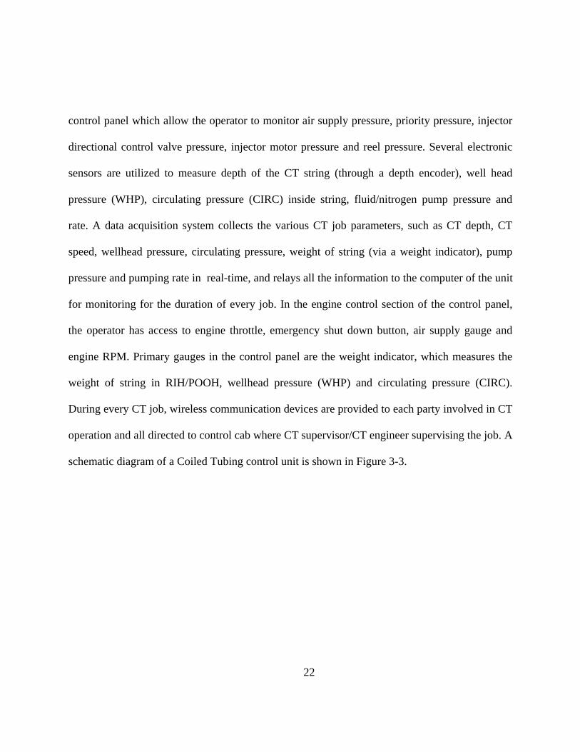
control panel which allow the operator to monitor air supply pressure, priority pressure, injector
directional control valve pressure, injector motor pressure and reel pressure. Several electronic
sensors are utilized to measure depth of the CT string (through a depth encoder), well head
pressure (WHP), circulating pressure (CIRC) inside string, fluid/nitrogen pump pressure and
rate. A data acquisition system collects the various CT job parameters, such as CT depth, CT
speed, wellhead pressure, circulating pressure, weight of string (via a weight indicator), pump
pressure and pumping rate in real-time, and relays all the information to the computer of the unit
for monitoring for the duration of every job. In the engine control section of the control panel,
the operator has access to engine throttle, emergency shut down button, air supply gauge and
engine RPM. Primary gauges in the control panel are the weight indicator, which measures the
weight of string in RIH/POOH, wellhead pressure (WHP) and circulating pressure (CIRC).
During every CT job, wireless communication devices are provided to each party involved in CT
operation and all directed to control cab where CT supervisor/CT engineer supervising the job. A
schematic diagram of a Coiled Tubing control unit is shown in Figure 3-3.

3.1.4. C
T
The CT
and cons
and swiv
mechanis
plastic be
diameter
the drum
proper ar
synchron
Coiled Tubi
The main fun
reel comes
ists of drum
vel assembl
sm. The drum
ending defor
, flange wid
m, for each C
rrangement
ny with the r
F
ing Reel
nction of the
skid-mounte
m (spool), lev
ly, depth m
m is a spool
rmation in o
th and tubin
CT diameter
of the pipe
reel and allo
Figure 3-3:
e CT reel is t
ed for offsho
vel-wind ass
measurement
on which st
rder to be st
ng stack heig
r. The level
as it is been
ows for the p
23
Coiled Tub
to store the
ore operatio
embly (trave
t (mechanic
tring is store
tored on the
ght, dictate th
-wind assem
n stored on t
proper arrang
bing control
CT string an
on or trailer-
elling block)
cal counter)
ed. We remar
drum. The r
he length of
mbly is a m
the drum. Th
gement of th
l unit
nd protect it
-mounted for
), high press
) and Reel
rk that the st
reel dimensi
f the CT that
mechanism w
he travelling
he pipe in su
t against dam
r land opera
sure treating
hydraulic
tring underg
ions, such as
t can be store
which ensure
g block mov
ubsequent w
mage.
ations
lines
drive
goes a
s core
ed on
es the
ves in
wraps.

24
A small hydraulic motor can override the motion of the travelling block if a correction is
required for a proper spooling procedure. The high pressure manifold and swivel assembly
consists of different elements of “treating irons” (i.e., high-pressure piping) and allows for
pumping fluid while deploying (RIH) or retrieving (POOH) the CT, during well intervention
operation. The swivel mechanism provides pumping capability while maintain the rotational
motion of the drum for the duration of the job. The high pressure treatment fluid travels from the
fluid/nitrogen pump to the high pressure manifold and then into the CT string through the swivel
joint. The next component in the CT reel is the mechanical depth counter. The depth control box
provides length of CT movement in terms of depth with respect to the surface. This is a backup
system for electronic depth measuring system which is explained in Section 3.1.5 about the
injector head.
Finally, the CT Reel hydraulic drive mechanism provides the motion for deployment and
retrieval of string in wellbore. Direct drive and right angle drive are two configurations used in
CT reel equipment. In the direct drive configuration, the hydraulic motor connects directly to the
drum. In the right angle drive configuration, the hydraulic motor connects to the reel drum
through chain and sprocket drive. A Coiled Tubing Reel unit is shown in Figure 3-4.

3.1.5. C
T
the inject
the pipe
hydraulic
inside ch
while RI
string. Th
the contr
Coiled Tubi
The coiled tu
tor head. Tw
into or retri
c motor. Out
hain tension
IH and/or P
he injector b
rol cabin. Th
ing Injector
ubing string
wo sets of g
ieve the pipe
tside chain te
er system a
OOH. Spec
brake is loca
he injector he
Figure 3-4
r Head and G
is run in hol
ripper block
e out of the
ensioners ma
applies force
ific sizes of
ated on each
ead has two
25
4: Coiled Tu
Gooseneck
le (RIH) and
ks, which are
wellbore. E
aintain tensi
e on gripper
f gripper blo
h hydraulic m
different sp
ubing Reel u
d pulled out
e connected
Each chain d
ion in the ch
r blocks to
ocks are us
motor and i
peed settings
unit
of hole (POO
d to two sets
drive is driv
hain and avoi
keep the CT
ed for each
s controlled
s, high and lo
OH) by mea
s of chains, i
ven by a sep
id loosening
T string han
h diameter o
d by a valve
ow, the choi
ans of
inject
parate
g. The
nging
of CT
from
ice of
26
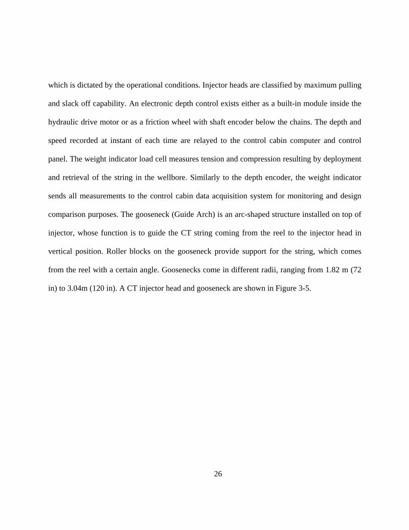
which is dictated by the operational conditions. Injector heads are classified by maximum pulling
and slack off capability. An electronic depth control exists either as a built-in module inside the
hydraulic drive motor or as a friction wheel with shaft encoder below the chains. The depth and
speed recorded at instant of each time are relayed to the control cabin computer and control
panel. The weight indicator load cell measures tension and compression resulting by deployment
and retrieval of the string in the wellbore. Similarly to the depth encoder, the weight indicator
sends all measurements to the control cabin data acquisition system for monitoring and design
comparison purposes. The gooseneck (Guide Arch) is an arc-shaped structure installed on top of
injector, whose function is to guide the CT string coming from the reel to the injector head in
vertical position. Roller blocks on the gooseneck provide support for the string, which comes
from the reel with a certain angle. Goosenecks come in different radii, ranging from 1.82 m (72
in) to 3.04m (120 in). A CT injector head and gooseneck are shown in Figure 3-5.

3.1.6. S
O
words, th
which pr
surround
Hydrauli
injector c
Stripper (St
One of the m
he CT string
rovides such
ded the CT s
ic pressure i
chains, and t
Figure 3-
tuffing Box)
main applica
g can be depl
h capability i
string and is
s applied to
the hydraulic
-5: Coiled T
)
ations of Co
loyed and re
is called stri
s a part of t
a set of ela
c pressure on
27
Tubing injec
oiled Tubing
etrieved whil
ipper (Stuffi
the well con
astomeric ru
n the strippe
ctor head an
g is in live w
le the well i
ing Box). Th
ntrol stack in
ubbers. The
er can be via
nd Goosenec
wellbore con
is in product
he stripper i
n a CT rig-u
stripper is lo
a the control
ck
nditions. In
tion. The ele
is a dynamic
up configura
ocated below
ls available i
other
ement
c seal
ation.
w the
in the
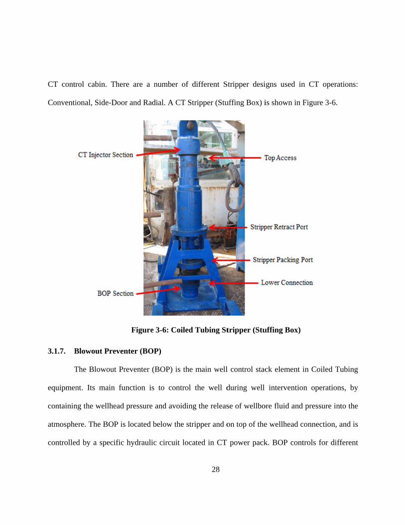
CT contr
Conventi
3.1.7. B
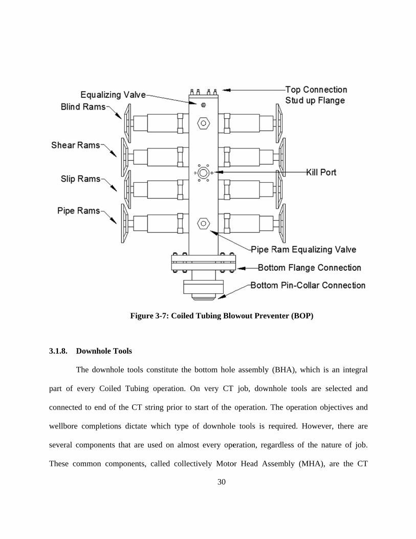
T
equipmen
containin
atmosphe
controlle
rol cabin. T
ional, Side-D
Blowout Pre
The Blowou
nt. Its main
ng the wellhe
ere. The BO
d by a spec
There are a
Door and Ra
Figure
eventer (BO
ut Preventer
n function i
ead pressure
P is located
ific hydrauli
number of
adial. A CT S
e 3-6: Coiled
OP)
(BOP) is th
s to control
e and avoidin
below the st
ic circuit loc
28
different S
Stripper (Stu
d Tubing St
e main well
l the well d
ng the releas
tripper and o
cated in CT
Stripper desi
uffing Box) i
tripper (Stu
l control stac
during well
se of wellbo
on top of the
power pack
igns used in
is shown in F
uffing Box)
ck element i
interventio
ore fluid and
e wellhead c
k. BOP cont
n CT operat
Figure 3-6.
in Coiled Tu
n operation
pressure int
connection, a
trols for diff
tions:
ubing
ns, by
to the
and is
ferent

29
functions are located in the CT control cabin. There are four hydraulic rams on every
conventional BOP: Blind, Shear, Slip and Pipe rams assembly. The blind rams seal the wellbore
and do not allow the passage of fluid from the wellhead. The function of the shear rams is to cut
the pipe during an emergency in well control or on a stuck-pipe situation. On both side, the shear
rams contain blades designed to cut the pipe. The function of the slip rams is to hold the pipe in
place and prevent the pipe from being pushed out of the well or from falling into the wellbore.
Finally, the pipe rams seal the area surrounding the pipe and isolate the wellbore while the pipe
is still hanging from the slip rams. There are other components in BOP such as the kill port,
equalizing valves, pressure port and top/bottom connections. There are different types of BOP
designs and configurations, based on operational requirements, classified as Quad BOP, Dual
Combi BOP and single BOP rams. A schematic diagram of a Coiled Tubing Blowout Preventer
(BOP) is shown in Figure 3-7.
3.1.8. D
T
part of e
connecte
wellbore
several c
These co
Downhole T
The downho
every Coile
d to end of
completion
components
ommon com
Figure 3
Tools
ole tools con
d Tubing o
the CT strin
ns dictate w
that are use
mponents, ca
3-7: Coiled
nstitute the b
operation. O
ng prior to
which type o
ed on almos
alled collect
30
Tubing Blo
bottom hole
On very CT
start of the
of downhole
st every ope
tively Moto
owout Preve
e assembly (
job, down
operation. T
e tools is re
eration, rega
or Head Ass
enter (BOP)
(BHA), whi
nhole tools
The operatio
equired. Ho
ardless of th
sembly (MH
)
ich is an int
are selected
on objective
owever, ther
he nature of
HA), are the
tegral
d and
s and
re are
f job.
e CT

31
connector, check valves, Disconnect and Circulating components. The first component of every
downhole tool is the CT connector, which connects to the end of the string with different
gripping methods such as dimple, roll-on and grapple. Once the CT connector is installed on the
string, the rest of downhole tools screw in on the bottom of the connector. Double check valves
prevent the influx of wellbore fluid into the string as it RIH or POOH. The next component in
the Motor Head Assembly is the CT Disconnect. When the BHA gets stuck in the wellbore, the
CT Disconnect is activated and the CT string is free to be retracted to the surface. The release
mechanism in the CT Disconnect is either mechanically activated or pressure activated. The last
component in the MHA is the circulating component, which provides extra circulating ports
when high-rate pumping is required, and is activated by ball drop or pressure differential.
In addition to the MHA, there is a wide range of different downhole tools available ,
depending on the objectives of the operation. There are specific downhole tools for different
operations such as cleanout, milling, logging, fishing, perforating, cementing, drilling, acidizing,
velocity string and fracturing. A schematic diagram of a Downhole Bottom Hole Assembly
(BHA) is shown in Figure 3-8.
Figur
3.2. C
C
nature of
executed
3.2.1. C
T
objective
in order
workover
T
out of th
and to cr
e 3-8: Down
Coiled Tub
Coiled Tubin
f required w
d. In the follo
Coiled Tubi
The most com
e of a cleano
to restore w
r operations
The cleanout
e wellbore.
reate a high
nhole Bottom
bing Appl
ng is used i
ell intervent
owing, the di
ing Cleanou
mmon appli
out operation
well produc
.
t is achieved
In order to
annular vel
m Hole Ass
lications
in different t
tion, a specif
ifferent type
ut
cation of Co
n is removing
ction and pr
d by pumpin
do so, it is n
locity (i.e., t
32
embly (BHA
types of we
fic type of C
es of CT inte
oiled Tubing
g fills such a
repare the w
ng treatment
necessary to
the velocity
A) – (Bakke
ell interventi
Coiled Tubin
ervention app
g is fill clean
as scales, deb
wellbore for
fluid into th
o add a visco
of the fluid
e Oil Tools C
ion operatio
ng applicatio
plications ar
nout from we
bris, sands, w
r the next w
he wellbore
ous gel to th
d in the annu
Catalog 200
ns. Based o
on is selected
e introduced
ellbore. The
wax, asphalt
well services
and circulat
he treatment
ular cross-se
01)
on the
d and
d.
main
t etc.,
s and
ting it
fluid
ection

33
between the CT and the wellbore). Another method employs a treatment fluid containing
nitrogen, and its purpose is to energize the fluid and increase the annular velocity for proper
cleanout.
3.2.2. Coiled Tubing Milling
One of the methods in the completion of horizontal reservoirs is fracturing services. Plug
and perforation is one of the methods used with fracturing , in order to complete horizontal
reservoirs. Prior to each stage of fracturing, a plug is set and the corresponding zone of interest is
perforated, which exposes the reservoir to the fracturing treatment. Once fracturing is completed,
it is required to remove all isolation plugs from the wellbore. At this stage, Coiled Tubing is
required to perform milling. The Coiled Tubing conveys a milling tool, consisting of a number of
components such as, MHA, Jars, downhole vibrating tool, motor and mill. Coiled Tubing and
milling tool are used to remove the plugs and circulating debris out of the wellbore. As
mentioned before, the plugs can be milled under live well condition.
3.2.3. Coiled Tubing Logging
Open-hole and cased-hole logging are methods to obtain information about a reservoir
by using different suits of downhole sensors. Traditionally, Wireline provides this type of
operation in vertical and deviated wellbores. One of the methods to perform logging in highly
deviated and horizontal completions is the application of Coiled Tubing. The electronic line (e-
line) is inserted into the CT string to provide a medium to transfer information from downhole
sensors to the surface. In this way, the CT string is enabled to perform logging in open-hole and
34
cased-hole completions. The logging head downhole tool connected to the end of CT provides a
platform for different Wireline sensors to be attached to CT string. One of the most common
applications of Coiled Tubing logging is production logging. By deploying a CT equipped with
an e-line, the production data are captured and relayed real-time to the surface . The deployment
of a downhole camera is among other application of CT strings with e-line.
3.2.4. Coiled Tubing Matrix Stimulation (Acidizing)
The decline in production rate, compared to the potential production capacity of a
reservoir, is one of the important challenges in the life cycle of an oil/gas well. The production
decline could be the result of near-wellbore restrictions (perforations) or formation damage.
Considering reservoir parameters and well testing data, one of the means to tackle this problem is
matrix stimulation, which includes washing perforations and the injection of acid treatment
fluids into the formation in order to reduce the damage in reservoir or to establish new paths in
the reservoir to recover the expected production rate. CT is used to pump different acid treatment
fluids while moving the CT string across the targeted intervals.
3.2.5. Coiled Tubing Drilling
One of the methods to increase production in low pressure matured reservoirs is to drill a
new lateral “leg” in the main wellbore. A low reservoir pressure requires an underbalanced
intervention while the well is producing. Underbalanced drilling avoids reservoir damage due to
overbalanced conventional drilling solutions. From an economic perspective, hydrocarbon
production during drilling makes the operation more cost-effective. A Coiled Tubing drilling

35
package is capable of drilling a new lateral leg in underbalanced conditions. A specialized
drilling BHA is conveyed with a CT string to drill the lateral leg connected to the main wellbore.
The application of nitrified drilling fluid ensures a low bottom hole pressure, yet maintaining
enough medium to carry the cuttings resulting from drilling to the surface. A specially designed
drilling tower is required in CT drilling. The drilling well control stacks ensure a safe and
controlled condition while the well is producing.
3.2.6. Coiled Tubing Fracturing
One of the completion methods in shallow vertical wellbores is Coiled Tubing
fracturing. A straddle packer type is used as the downhole tool in this application. The straddle
packer isolates the zone of interest at each stage. High-pressure treatment fluid mixed with sands
(slurry) is pumped down through the CT string into an isolated zone to fracture each reservoir
interval. The use of CT fracturing services provides multiple fracturing in a single wellbore.
High-pressure nitrogen-based fluid or CO2-based fracturing fluid are injected through CT string
to perform fracturing. Employing this method of intervention reduces the completion time and
cost, in addition to improving post-treatment cleanup and production.
3.2.7. Coiled Tubing Cementing
Coiled Tubing is used to perform cement squeeze and cement plug placement jobs,
which are required in cases of well abandonment, casing repair, zonal isolation and water gas
shutoff. Cement squeeze is a process which cement is forced into the formation by means of the
application of pressure through perforations in the wellbore. Cement plug placement is a process
36
which a designed volume of cement is spotted in the wellbore to isolate sections of the reservoir.
CT cementing is the application of pumping cement slurry through the CT string in order to
squeeze cement or place a cement plug in a wellbore. The use of Coiled Tubing cementing
provides precise placement and a lower contamination of the cement slurry due to a lower
exposure to the wellbore fluid.
3.2.8. Coiled Tubing Fishing
The retrieving of a lost BHA, parted string, dropped object or bridge plug is a procedure
called “fishing”, for which a CT string can be used (CT fishing), even in a live well. There is a
wide variety of downhole tools available, depending on the nature of the fishing operation. The
stiffness of CT and the possibility to deploy the CT in a horizontal wellbore are among the
advantages of such intervention. In attempting to latch on the fish, pumping through the CT
string can activate a fishing BHA. The Circulation of different types of fluid in the CT string
assists the retrieval process. For the case of a stuck fish, the CT can safely exercise designed pull
or slack off in order to free up the fish.
3.2.9. Coiled Tubing Nitrogen Kick off
When hydrostatic pressure of column of wellbore fluid exceeds reservoir pressure, well
production is ceased. Nitrogen kick off job through CT string is required to recover well
production. Pumping nitrogen though CT string at designed depth reduces wellbore fluid density;
therefore, wellbore hydrostatic pressure is reduced. By reducing downhole pressure reservoir
stars producing. Nitrogen pump unit delivers nitrogen gas through CT string.

37
3.2.10. Application of Coiled Tubing Equipped with Optical Fibers
CT strings equipped with optical fibers are among the latest developments in Coiled
Tubing services. An optical-fiber-equipped string is injected inside the CT string and functions
as a data delivery medium for downhole information. The major advantage of an optical fibers
CT string compared to an e-line CT string is its ability to capture the thermal logging of the
entire wellbore during operation for a wide variety of applications, including gas well production
logging, matrix stimulation, leak detection, Fracture monitoring, Water injection etc. Moreover,
the diameter of an optical fiber is smaller than that of an e-line, which allows for pumping
different treatment fluids with high “pumping rate” (i.e., flow) while receiving real-time
downhole information .
3.3. Job Design Considerations for Coiled Tubing Services
Prior to every Coiled Tubing job, it is required to examine and verify the feasibility of
the intervention operation. This includes tubing force modeling (TFM), fatigue analysis of the
CT string and the evaluation of the pressure limits of the CT string during the operation. In
tubing force modeling, the design engineer determines whether or not the selected CT string can
reach to the desired depth to perform required operation.
As a CT string deploys into a wellbore, a drag force between CT string and wellbore develops.
Therefore, the more the CT string runs through the wellbore, the more drag forces occur, and
therefore the more axial force is required to continue running the CT string. Once the axial force
increases to a certain threshold, CT string turns into a sinusoidal buckling configuration. This

38
threshold value of the axial force is called sinusoidal load or SinusoidalF . As the CT continues
running in hole (RIH), the axial compressive force increases and, at certain load, the CT string
turns into a helical buckling configuration. This load is called helical buckling load or HelicalF .
When the CT string turns into the helical buckling mode, the drag force starts to increase
dramatically. Indeed, the contact force between CT string and wellbore increases as a result of
the increasing axial compressive force. When the force at the surface (slack-off weight) cannot
be transferred to the downhole end, the CT string stops and no further progression is possible.
This situation is called “lock-up”.
In order to calculate the lock-up depth, it is necessary to use wellbore data which can be
summarized as: wellbore trajectory (Measured Depth, Inclination Angle and Azimuth Angle),
wellbore casing configurations and wellbore completions components. Friction in the wellbore
plays an important role in developing contact forces between CT string and wellbore. There are
several methods to reduce the effect of friction and the contact forces. One of such methods is
the application of a downhole vibration, which shall be explained in Section 3.4. When it has
been evaluated that the CT string can reach to the desired depth, two more criteria need to be
checked from an operation perspective: the fatigue life of the CT string and the operating
pressure envelope of string. These two design considerations are not the subject of this study.
3.4. Downhole Vibrating Tool
One of the main challenges of Coiled Tubing intervention in a long horizontal wellbore
is reaching to the target depth. As mentioned above, as the CT string progresses in the horizontal

39
section, the friction between CT string and wellbore increases, resulting in sinusoidal buckling
first and then in helical buckling. One of the means to eliminate or attenuate this problem is the
application of a downhole vibrating tool, which is a part of the downhole bottom hole Assembly
(BHA). The function of the downhole vibrating tool is to create a longitudinal vibration mode in
the CT string, which helps reducing the contact forces between wellbore and CT string.
Therefore, the CT string can progress further in wellbore and maximize its reach.
One brand of downhole tool vibrating tool is called “Agitator” and it is manufactured by
National Oil Varco (NOV, Houston, TX, USA). The Agitator tool consists of power section,
valve and bearing. The power section is basically a downhole motor which drives the valve
section. The valve and Bearing sections in turn generate pressure pulses which cause an axial
vibration motion in the CT string. The hydraulic energy of the pumped fluid is converted into
mechanical vibration by the Agitator. The downhole vibration generated by the Agitator reduces
the wellbore friction drag and allows for more force to be transferred from surface to downhole.
A schematic diagram of a downhole vibrating tool (Agitator) is shown in Figure 3-9.

Figuure 3-9: Dow
40
wnhole vibra
ating tool (AAgitator)
41
Chapter 4. Theoretical Background
In this chapter we report the existing theoretical relationships used in modeling a
buckled tubing inside a wellbore as follows:
Force-pitch relationships
Sinusoidal and helical buckling load criteria
Contact force for sinusoidally/helically buckled string in a horizontal wellbore
Axial force transmission relationships for a horizontal wellbore
Soft string model
Lock-up condition
Lubinski et al. (1962) presented the effect of helical buckling in a packer-tubing system
for several different configurations. The pitch-force relationship for helically buckled tubing was
developed based on energy methods. As shown in Figure 4-1, a string is hung in a vertical
wellbore without fluid in the casing, and a compressive Force (F) is applied to the downhole end
of the tubing. When this force is large enough (above the helical buckling force) the downhole
section of the string below the neutral point turns into the shape of a helix. The “neutral point” in
the string is the cross-section which is neither in tension nor in compression (Lubinski on et al.
1962). The cross-sections above the neutral point (neutral cross-section) are all in tension, and
the ones below are all in compression.

T
Where n
force (po
T
section) i
pitch yiel
The location
n is distance
ositive) in N
The relations
is described
lds:
F
n of the neutr
e from the en
(lb) and w
ship between
by Equation
igure 4-1:B
ral point is g
nd of tubing
is weight of
n pitch (Figu
n ( 2.1) (see
42
uckling of s
given by the
Fn
w ,
to the neutr
f pipe per un
ure 4-2) and
Appendix A
string in we
expression
ral point in m
nit length in
d compressiv
A for details
ellbore
m (in), F is
air in N/m (l
ve force (for
s). Solving E
( 4.
s the compre
lb/in).
r helical buc
Equation ( 2.1
1)
essive
ckling
1) for
43
8EIp
F ,
( 4.2)
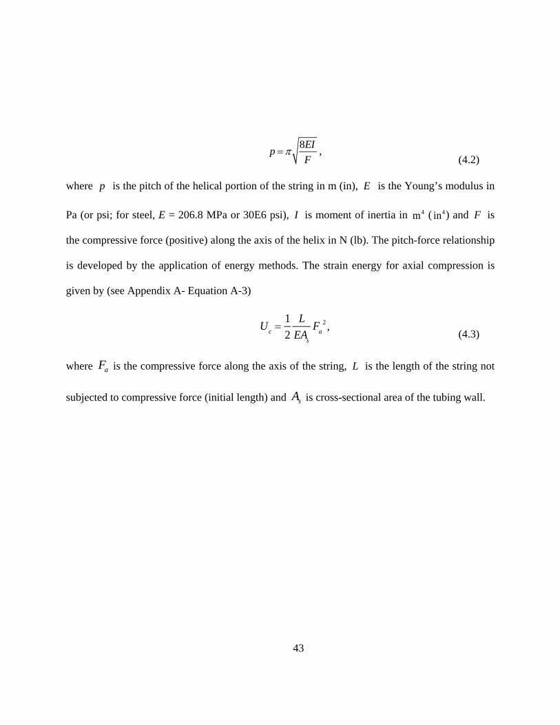
where p is the pitch of the helical portion of the string in m (in), E is the Young’s modulus in
Pa (or psi; for steel, E = 206.8 MPa or 30E6 psi), I is moment of inertia in m4 ( in4) and F is
the compressive force (positive) along the axis of the helix in N (lb). The pitch-force relationship
is developed by the application of energy methods. The strain energy for axial compression is
given by (see Appendix A- Equation A-3)
Uc
1
2
L
EAs
Fa
2 , ( 4.3)
where aF is the compressive force along the axis of the string, L is the length of the string not
subjected to compressive force (initial length) and sA is cross-sectional area of the tubing wall.

Figure 44-2:Helix ge
44
ometry and
d pitch of buuckled strinng
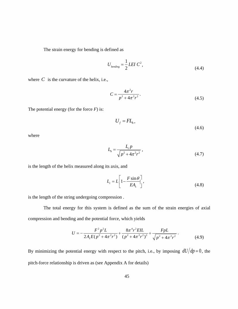
45
The strain energy for bending is defined as
Ubending
1
2LEI C 2 ,
( 4.4)
where C is the curvature of the helix, i.e.,
2
2 2 2
4
4
rC
p r
. ( 4.5)
The potential energy (for the force F) is:
f hU FL , ( 4.6)
where
2 2 24c
h
L pL
p r
,
( 4.7)
is the length of the helix measured along its axis, and
sin1c
s
FL L
EA
,
( 4.8)
is the length of the string undergoing compression .
The total energy for this system is defined as the sum of the strain energies of axial
compression and bending and the potential force, which yields
2 2 4 2
2 2 2 2 2 2 2 2 2 2
8
2 ( 4 ) ( 4 ) 4s
F p L r EIL FpLU
A E p r p r p r
. ( 4.9)
By minimizing the potential energy with respect to the pitch, i.e., by imposing dU dp 0, the
pitch-force relationship is driven as (see Appendix A for details)

46
2
2
8 EIF
p
.
( 4.10)
Paslay and Bogy (1964) studied the stability of a rod in a constrained cylindrical
geometry using energy methods and assuming that the rod maintains constant contact with the
cylindrical constraint (wellbore), and the tubing curvature does not change. The loads on the rod
consist of its weight (gravitational forces), axial force and moment at both ends (Figure 4-3). In
order to find the stability criteria, the total potential energy of this system must be minimized.
The total potential energy can be written as
V U ,
( 4.11)
where U is elastic strain energy and is the work of the external forces.

T
Two con
which im
The change i
ditions are r
mposes an ex
Figure
in total poten
V U
required to m
xtremum on t
e 4-3: Confi
ntial energy
1
2!U
minimize the
the energy, a
47
guration of
( V ) for th
2 21
2!U
total potent
U
and
f a string in
his system is
31
3!U
tial energy fo
0
a wellbore
s:
31...
3! .
or this system
( 4.
m, i.e.,
( 4.
12)
13)

48
2 2 0U
( 4.14)
which means that the extremum is actually a minimum. Developing the expression for the
horizontal case ( 90 ) and assuming that the rod is at contact with the casing (wellbore) at all
times, imposing that 2V 0 yields
( )
2 42
2 2 4
1(1 )
ncr
L AgP EI n
L n EIr
,
( 4.15)
where ( )ncrP is critical load, is the Poisson’s ratio,
2 (1 )
1 2
GE
( 4.16)
is the elastic modulus in uniaxial strain (as opposed to the Young’s modulus E, which is the
elastic modulus in uniaxial stress), L is length of rod, r is the clearance between rod and
casing, gA is the weight per unit length of rod and n is the order of the buckling mode.
By assuming k gA r (elastic foundation constant), Equation ( 4.15) reduces to the
solution of a finite beam on an elastic foundation. By substituting the expression of the modulus
E , the critical force becomes
2 2 42
2 2 4
1
1 1 2crit
L AgF EI n
L n EIr
.
( 4.17)
Replacing Ag with w and imposing 0.3 yields a multiplicative coefficient of 0.942,
which can be approximated by 1, and critF becomes

49
2 2
crit
n w LF EI
L r n
.
( 4.18)
The first buckling mode ( n 1) is found by minimizing critF , i.e. (Dawson and Paslay,1984),
0critF
n
,
( 4.19)
which yields
n2 L4w
4EIr , ( 4.20)
and
2crit
EIwF
r ,
( 4.21)
where critF is the required compressive force for the rod to transition to the sinusoidal
configuration in horizontal wellbore (see Appendix B for details).
As the axial load continues increasing above the sinusoidal buckling load, the rod turns
into a helical configuration once the axial load reaches the helical buckling load. The helical
buckling load can be derived by minimizing the energy function with respect to m L p
(number of full waves in buckled pipe). The strain bending energy bU , the external work eW and
the potential energy V are

50
Ub
8 4EILr 2
(L m)4 ,
( 4.22)
We
2FL 2r 2
(L m)2 ,
( 4.23)
V wLr ,
( 4.24)
respectively. The total energy U is the set to zero (Chen et al., 1989),
U WeU
bV 0.
( 4.25)
Solving the above equation with respect to F yields the helical buckling force
2 2* 4
2
m w LF EI
L r m
. ( 4.26)
By minimizing the helical buckling force ( *F ) with respect to number m of full waves in the
buckled rod, i.e.,
*
0F
m
,
( 4.27)
the helical buckling load is derived as (see Appendix C for details)
* 2 2EIw
Fr
. ( 4.28)
When the axial compressive force exceeds the sinusoidal buckling load, the string
transitions into a sinusoidal configuration. Therefore, a new contact force is developed. In order

to calcul
half sine
under con
A
buckling
develops
buckling
ate the sinus
-wave buckl
nditions of s
As the comp
load, the
. As for the
in a horizon
soidal conta
ling deflecti
sinusoidal bu
Figure 4-4:
pressive axia
string trans
case of the
ntal wellbore
act force in t
on in a horiz
uckling wall
: Sinusoidal
al load contin
itions into
contact forc
e as been cal
51
the wellbore
zontal wellb
contact forc
2
8Sin
rFN
EI
l buckled str
nues to incre
a helical c
ce in sinusoi
lculated usin
e, energy me
bore (Figure
ce was evalu
I.
ring in hori
ease and bec
onfiguration
idal buckling
ng energy me
ethods are a
4-4). The w
uated by Wu
izontal wellb
comes greate
n, and a ne
g, the contac
ethods as (W
again applied
wall contact
(1995) as
( 4.2
bore
er than the h
ew contact
ct force in h
Wu, 1995)
d to a
force
29)
elical
force
elical

I
1993c)
w
coefficien
unbuckle
In and inclin
where is
nt and ew
ed pipe in an
Figure 4-
ned wellbore
the angle
is effective
n inclined we
5: Helical b
e, the frictio
F
of wellbore
e weight of
ellbore has b
0( )F x F
52
2
4Hel
rFN
EI
buckled strin
on force for
sinf eF w
e with resp
the pipe p
been derived
sineW
2
I.
ng in horizo
an unbuckl
n ,
pect to the
per unit leng
as (Wu, 199
coseW x
ontal wellbo
ed pipe is (W
vertical,
gth. The ax
95)
x ,
( 4.3
ore
Wu and Juv
( 4.3
is the fri
xial force fo
( 4.3
30)
vkam,
31)
iction
or an
32)

where F
axis from
F
W
exceeds t
as a resul
force, co
Juvkam,
0F is the axia
m the downho
For a horizon
When the tu
the sinusoid
lt of contact
onsisting of
1993c)
al load at th
ole end.
ntal wellbore
Figure
ubing turns t
dal or helical
forces. The
drag (due to
he downhole
e ( 90 , F
(F x
e 4-6: Force
to the sinuso
l buckling lo
axial force
o sinusoidal/
53
end ( x 0
Figure 4-6) t
0)x F W
e balanced i
oidal or heli
oad), an extr
for such cas
/helical cont
) and x is m
this expressi
eW x .
in horizonta
ical bucklin
ra drag force
se is no long
tact) and we
measured al
ion reduces t
al wellbore
ng shape (i.e
e is introduc
ger linear. Th
eight of the
long the wel
to (Wu, 1995
( 4.3
e., the axial
ced to the sy
he overall co
pipe is (Wu
llbore
5)
33)
force
ystem
ontact
u and

54
sint n ew w w , ( 4.34)
where tw is the overall contact force per unit length between pipe and wellbore wall, nw is the
contact force per unit lenght resulting from the helical buckling of the pipe and ew is the
effective weight of pipe per unit length in wellbore.
The force balance for an element of pipe undergoing sinusoidal/helical buckling in an
inclined wellbore can be expressed by (Wu and Juvkam, 1993c)
cos sin cost e e n eF w x w x w w w x , ( 4.35)
from which
sin cose n e
dFw w w
dx ,
( 4.36)
and using the expression of nw ,
2
sin cos4e e
dF rFw w
dx EI
. ( 4.37)
The axial force corresponding to sinusoidal and helical shapes can be derived by
applying expressions of the contact forces for sinusoidal/helical buckling, which have been
already calculated in Equations ( 4.29) and ( 4.30).
The axial force distribution for sinusoidally buckled pipe in a horizontal wellbore is
(Wu, 1995)

55
0
8( ) tan arctan
8 8e e
e
EIW rW rF x x F
r EI EIW
, ( 4.38)
and for a helically buckled pipe in a horizontal wellbore is (Wu, 1995)
0
4( ) tan arctan
4 4e e
e
EIW rW rF x x F
r EI EIW
. ( 4.39)
To find the axial compressive load for a CT string inside a curved wellbore described by
the curvilinear abscissa s , the soft string model (Bhalla, 1994) is used to describe axial load
distribution as
dF wdscos d sinF 2 (Fd wdssin )2 ,
( 4.40)
where dF is the incremental change in axial force (no buckling), w is weight per unit length of
the pipe, is inclination angle of the wellbore with respect to the vertical, and d is the
incremental change in azimuth angle of the wellbore survey (i.e., the curve that the wellbore
describes in space), and ds is the increment in curvilinear abscissa along the wellbore survey.
Positive sign applies to the pull-out-of-hole (POOH) condition and the negative sign applies to
the slack-off case (or run-in-the-hole, RIH).
When the axial compressive force exceeds the helical buckling load, the axial load
distribution will change and the contact force due to helical buckling must be accounted for. The
incremental change in axial force for a helically buckled string is given by (Bhalla, 1994)
2
2 2cos sin ( sin )4
rFdF wds d F Fd wds
EI
.
( 4.41)
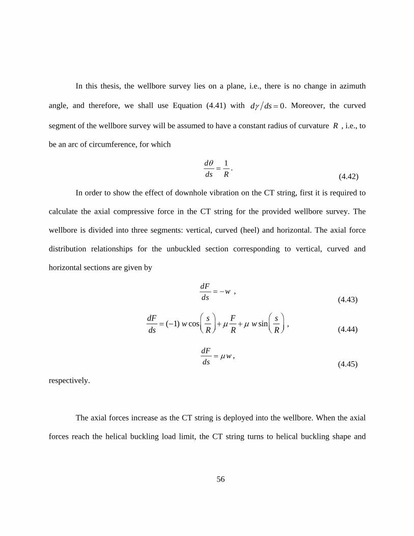
56
In this thesis, the wellbore survey lies on a plane, i.e., there is no change in azimuth
angle, and therefore, we shall use Equation ( 4.41) with d ds 0. Moreover, the curved
segment of the wellbore survey will be assumed to have a constant radius of curvature R , i.e., to
be an arc of circumference, for which
1d
ds R
.
( 4.42)
In order to show the effect of downhole vibration on the CT string, first it is required to
calculate the axial compressive force in the CT string for the provided wellbore survey. The
wellbore is divided into three segments: vertical, curved (heel) and horizontal. The axial force
distribution relationships for the unbuckled section corresponding to vertical, curved and
horizontal sections are given by
dFw
ds ,
( 4.43)
dF
ds (1) w cos
s
R
F
R w sin
s
R
, ( 4.44)
dFw
ds ,
( 4.45)
respectively.
The axial forces increase as the CT string is deployed into the wellbore. When the axial
forces reach the helical buckling load limit, the CT string turns to helical buckling shape and

57
axial load distribution changes for each section of wellbore due to the additional drag forces
caused by the contact with the wellbore.
The criteria for helical buckling load criteria for the vertical section is (Wu and Juvkam,
1995a)
FHelical _Veritical
5.55 EIw2 1/3 ,
( 4.46)
for the curved section (with radius of curvature R) is (Qui et al.,1998)
2
_
8 1 sin1
2Helical Curved
EI w rRF
rR EI
,
( 4.47)
and for the horizontal section is (Chen et al.,1998)
_ 2 2Helical Horizontal
EIwF
r .
( 4.48)
When the axial compressive force exceeds the helical buckling load on each section,
new load distribution relationship are required due to the extra contact forces resulting from the
helical buckling. For a helically buckled string, the axial compressive load distribution in the
vertical segment is (Mitchell, 1986b)
2
4
dF rFw
ds EI
,
( 4.49)
for the curved segment is (Bhalla, 1994)
dF
ds (1) w cos
s
R
F
R w sin
s
R
rF 2
4EI ,
( 4.50)
and for the horizontal segment is (Wu and Juvkam, 1993c)
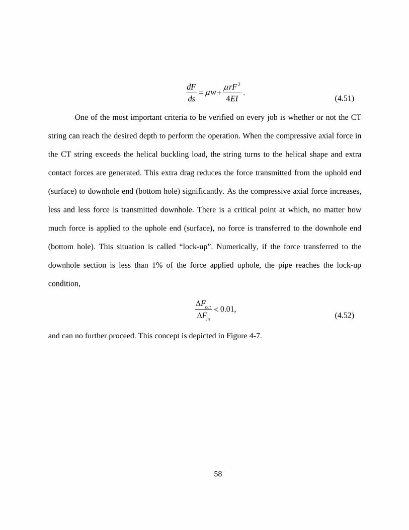
58
2
4
dF rFw
ds EI
. ( 4.51)
One of the most important criteria to be verified on every job is whether or not the CT
string can reach the desired depth to perform the operation. When the compressive axial force in
the CT string exceeds the helical buckling load, the string turns to the helical shape and extra
contact forces are generated. This extra drag reduces the force transmitted from the uphold end
(surface) to downhole end (bottom hole) significantly. As the compressive axial force increases,
less and less force is transmitted downhole. There is a critical point at which, no matter how
much force is applied to the uphole end (surface), no force is transferred to the downhole end
(bottom hole). This situation is called “lock-up”. Numerically, if the force transferred to the
downhole section is less than 1% of the force applied uphole, the pipe reaches the lock-up
condition,
Fout
Fin
0.01, ( 4.52)
and can no further proceed. This concept is depicted in Figure 4-7.

F
the helic
stress in
helical bu
from whi
Furthermore
cal buckling
the string i
uckling, i.e.,
ich the plasti
, the coiled
in the well
s given a co
,
ic yielding a
Figure 4-7:
tubing may
lbore (He an
ontribution d
max
axial force is
59
: Lock-up c
yield plastic
nd Kyllings
due to the a
F
As
F(d
I
s
condition gr
cally due to
stad, 1995).
axial force a
do
4)
Ir ,
raph
the bending
The maxim
and a contrib
g stress cause
mum compre
bution due t
( 4.5
ed by
essive
to the
53)
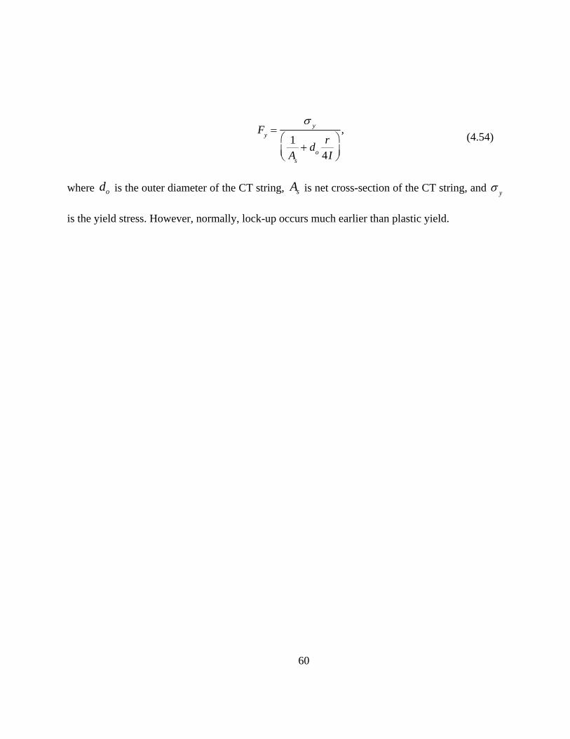
60
Fy
y
1A
s
do
r4I
, ( 4.54)
where od is the outer diameter of the CT string, sA is net cross-section of the CT string, and y
is the yield stress. However, normally, lock-up occurs much earlier than plastic yield.

61
Chapter 5. Modeling
This chapter presents the core result of this thesis: the proposed method of multiple
friction factors and its application to the modeling of a full wellbore. The modeling focuses on
the prediction of the improvement in force transfer and in the extension of the reach.
5.1. Modeling vs Published Experimental Data
Wu and Juvkam-Wold (1993c) validated their model of axial load distribution versus
small-scale experimental data. In their experiment, they simulated the drill string by means of a
brass bar with an outside diameter of 2.4 mm (0.095 in), and the wellbore by means of a plastic
pipe with an inside diameter of 25.7 mm (1.012 in). The dimensions of the brass bar and plastic
pipe were selected to reproduce, in a smaller scale, the geometry of the drill string and wellbore
encountered in real field operations. A hand-driven screw was used to apply an axial load from
the right side to the brass bar inside the plastic pipe. The applied load increased to the point
where brass bar turned to the helically buckled configuration. Two load cells were attached to
both sides of the brass bar in order to measure the applied axial load.
Different loads were applied via the hand-driven screw and Force In (uphole-end) and
Force Out (downhole-end) were measured. The recorded data was fitted to the helically buckled
model. Figure 5-1 shows the experimental data obtained by Wu and Juvkam-Wold (1993c). For a
straight shape in a horizontal wellbore, the axial force starts to increase in order to buckle the
pipe while input and output forces are being measured. The applied axial load is increased and,
as a result, the configuration of the rod changes from straight to sinusoidal and later on to helical.

In Figur
helical)
transferre
the axial
to Equati
the helica
F
O
Wu and J
(1993c)
buckled s
e 5-2, the a
are shown
ed before th
load transfe
ion ( 4.38).
ally buckled
Figure 5-1: E
Originally, th
Juvkam-Wo
did not pres
sections. Ho
axial force
against the
he buckling o
erred when th
The black cu
d configuratio
Experiment
he equations
ld (1993c) a
sent the exp
owever, their
distributions
experiment
of pipe, acc
he pipe attai
urve represe
on, accordin
al data extr
s for the stra
and have bee
perimental d
r theoretical
62
s for all 3
tal data. Th
ording to Eq
ins the sinus
ents the axia
ng to Equatio
racted from
aight and sin
en added in t
data correspo
model aime
configuratio
he green lin
quation ( 4.3
soidally buck
al load transf
on ( 4.39).
Wu and Ju
nusoidal con
this work. In
onding to th
ed at describ
ons (straight
ne represent
32). The red
kled configu
ferred when
uvkam-Wol
nfigurations w
n fact, Wu an
he straight a
bing the axia
t, sinusoidal
ts the axial
curve repre
uration, acco
the pipe tur
d (1993c)
were not use
nd Juvkam-W
and sinusoil
al load transf
l and
load
esents
ording
rns to
ed by
Wold
ldally
ferred
for the he
with the
helically
This cou
neglected
Figure
N
effect of
performe
this thesi
elically buck
experiment
buckled sec
uld be cause
d the bounda
5-2: axial lo
Newman et
f vibration
ed in straight
is, the exper
kled section
tal data. A
ction) and th
ed by the f
ary condition
oad distribu
al. (2007, A
and rotatio
t and curved
rimental dat
(black curve
deviation b
he experimen
fact that the
ns.
ution theore
A, 2007, B a
n on the r
d tubes, whic
ta correspon
63
e, described
between the
ntal data is o
ir model co
etical vs. exp
and 2009) co
reduction of
ch simulated
nding to the
by Equation
e black curv
observed for
onsidered an
perimental
onducted su
f friction. S
d wellbores w
straight tub
n ( 4.39) is in
ve (load tra
r high value
n infinitely
based on W
urface tests t
Several diff
with the sam
be is used. A
n close agree
ansfer mode
of axial loa
long string
Wu-Juvkam
to investigat
ferent tests
me geometrie
A 170 m (55
ement
el for
ading.
, i.e.,
test
te the
were
es. In
58 ft)

long, 73m
tubing w
factor be
cement b
were con
load cell
measure
vibrators
of 40 Hz
and witho
mm (2 7/8 in
with a 25.4 m
etween casin
blocks at sev
nnected to on
was connec
the “Force-
were used t
and an amp
out axial vib
Figu
n) corrosion-
mm (1 in) o
ng and tubin
veral location
ne end of str
cted at the o
-Out”, which
to apply vibr
plitude of 31
bration, for a
ure 5-3: Exp
-resistant all
outer diamet
g was 0.2. T
ns along the
ring to apply
opposite end
h represente
ration on the
14 N (700 lb
a straight we
perimental d
(20
64
loy (CRA) tu
ter was used
The wellbore
length of str
y and measu
d of the strin
ed the value
e string next
b). The expe
llbore are sh
data extract
007A, 2007B
ubing was u
d to model
e (straight tu
ring. An axia
ure, respectiv
ng in the sim
of force tra
to the axial
erimental da
hown in Figu
ted from Ne
B, 2009)
sed as a wel
Coiled Tub
ube) was fix
al force pisto
vely, the “Fo
mulated well
ansferred do
load piston,
ata for the fo
ure 5-3.
ewman et al
llbore and a
bing. The fri
xed in place
on and a load
orce-In”. An
lbore, in ord
ownhole. Ele
with a frequ
orce transfer,
l.
CRA
iction
e with
d cell
nother
der to
ectric
uency
, with
I
experime
models f
section (
2009). Th
applied t
theory an
T
sinusoida
experime
In this thesi
ental data fo
for the straig
(Equation ( 4
he closet ma
to all three
nd experimen
Figure 5-
The load d
al (Equation
ental data fo
is, three dif
or the non-v
ht section (E
4.39)), again
atch against
sections (str
ntal data for
-4: Axial loa
istribution p
n ( 4.38)) an
or the vibrat
fferent axia
ibrating case
Equation ( 4.3
nst the expe
the experim
raight, sinus
the non-vib
ading vs Ex
predicted b
nd helical se
ting case in
65
l load distr
e. Figure 5-
32)), sinusoi
erimental da
mental data i
soidal and h
brating case.
xperimental
y the mode
ection (Equ
n Figure 5-5
ribution mod
-4 shows the
idal section
ata by Newm
is obtained w
helical). The
data for no
els for the
ation ( 4.39)
5. In this ca
dels are use
e axial load
(Equation ( 4
mann et al.
with a frictio
ere is a good
on-vibrating
straight (E
)) are comp
ase, the best
ed to match
predicted b
4.38)) and h
(2007A, 20
on factor of
d match bet
g case
Equation ( 4
pared the ag
match has
h the
by the
elical
007B,
0.23,
tween
.32)),
gainst
been

obtained
is eviden
experime
Figure
I
propose
( 4.32)), s
effect of
string an
capture t
captures
T
with a fricti
nt that the u
ental data, pa
e 5-5: Axial
In order to a
to use three
sinusoidal (E
f the axial vi
nd wellbore.
the effect of
the improve
The apparent
ion factor of
use of a sin
articularly fo
loading vs E
achieve a bet
e different fr
Equation ( 4.
ibration on t
We shall s
f vibration o
ement in load
t friction fac
f 0.19, for al
ngle friction
or low value
Experiment
tter match w
friction facto
38)) and hel
the string is
show that th
on the reduc
d transfer co
ctors used to
66
ll three segm
factor prov
s of the Forc
tal data for v
with the expe
ors (apparen
lical section
s hypothesiz
he concept o
ction of fric
ompared to th
match the m
ments. Howe
vides a poor
ce In.
vibrating ca
erimental da
nt friction fa
n (Equation (
zed to reduce
of apparent
ction in the
he non-vibra
model agains
ever, for the
r match betw
ase – single
ata for the v
actors) for st
( 4.39)). In th
e the frictio
friction fact
wellbore an
ating case.
st the experim
vibrating ca
ween mode
friction fac
vibrating cas
traight (Equ
his approach
n factor bet
tor enables
nd, conseque
mental data
ase, it
l and
ctor
e, we
uation
h, the
tween
us to
ently,
are

Figure 5-
better m
vibrating
Figure 5
N
(straight,
vibrating
(2007A,
CT strin
_ _apparent straig
-6 shows tha
atch betwee
g case.
5-6: Axial lo
Now, we pro
, sinusoidal
g tool in CT
2007B, 200
ng farther in
0.05ght
at the applica
en model an
ading vs Ex
opose to app
and helical
intervention
09), axial vib
n the wellbo
_appare
ation of the
nd experime
xperimental
ply the evalu
l) to accoun
n. As shown
bration incre
ore. Figure
67
_sinusoidal 0.0ent
three appare
ents in the
l data for vi
uated appare
nt for the e
n by the exp
eases load tr
5-7 shows
09
ent friction f
straight and
ibrating cas
ent friction f
ffect of the
periments pe
ransfer and t
how the pr
_ _helicalapparent
factors does
d sinusoidal
se – multiple
factors for th
e application
erformed by
therefore en
roposed mod
l 0.185
indeed prov
sections fo
e friction fa
he three segm
n of a down
y Newmann
ables to pus
del captures
vide a
or the
actors
ments
nhole
et al.
sh the
s this

behavior
vibrating
5.2. F
D
in the de
downhol
transferre
the multi
. Indeed, a h
g case.
Figure 5-7:
Full Wellb
Downhole vi
epth that ca
e vibration
ed force? Or
iple apparen
higher load
: Axial Load
bore Mode
ibration caus
an be reache
tool requir
r, equivalent
nt friction fa
transfer is a
ding Model
eling
ses a reducti
ed. The que
red to prov
ly, in extens
actors. We sh
68
achieved in t
s for Vibrat
ion in wellbo
estion is no
vide in orde
sion of the re
hould menti
the vibrating
ting and No
ore drag and
ow: how mu
er to obtain
each? This c
ion that a m
g case comp
on-Vibrating
d, as a result,
uch friction
n a certain
can be answe
more accurate
pared to the
g Cases
, an improve
reduction i
improveme
ered by the u
e selection o
non-
ement
is the
ent in
use of
of the

friction f
and wellb
T
the path o
system su
is the len
“mMD”,
from the
to the ma
O
mMD. T
of the cu
factor would
bore, were a
To perform
of the well f
uch as: meas
ngth measur
meaning m
vertical axi
agnetic North
Our sample
he wellbore
urved sectio
be possible
available.
the modelin
from surface
sured depth,
red along th
meters of me
s and expres
h Pole and e
Figur
wellbore (F
inclination
on (heel sect
if more exp
ng, it is nece
e to the final
inclination
he path of t
asured depth
ssed in degr
expressed in
re 5-8: Mea
Figure 5-9) s
increases fro
tion) and re
69
perimental da
essary to kno
depth. The
angle and az
the wellbore
h; see Figur
rees, and the
degrees (Fig
asured depth
starts from s
om 0 deg in
emains cons
ata, with diff
ow the wellb
wellbore sur
zimuth angl
e, in meters
re 5-8, the in
e azimuth an
gure 5-9).
h in wellbor
surface at 0
n the vertical
stant at 90 d
fferent sizes
bore survey
rvey is defin
e. The meas
s (we shall
nclination an
ngle is measu
re
0 mMD and
l section to 9
deg all the
of Coiled Tu
y (trajectory)
ned by coord
sured depth (
use the not
ngle is mea
ured with re
extends to
90 deg at th
way throug
ubing
), i.e.,
dinate
(MD)
tation
sured
espect
5600
e end
h the

horizonta
axis is en
in azimut
considere
assumed
al section. F
ntirely conta
th angle on t
ed in this s
to be consta
For simplicity
ained in a ver
the axial com
study. More
ant, so that it
Fi
y, we assum
rtical plane (
mpressive lo
eover, the ra
ts axis is a qu
igure 5-9: W
70
me a zero azi
(Figure 5-10
oad distribut
adius of cur
uarter of circ
Wellbore sur
imuth angle
0). Therefore
tion (Equatio
rvature of t
cumference
rvey in 3D
e for this we
e all the effe
ons ( 4.40) an
the curved
(Figure 5-10
llbore, so th
ects of the ch
nd ( 4.41)) ar
(heel) secti
0).
hat its
hange
re not
on is

T
121.36 m
The CT
resulting
and a len
The casing (
mm (4.77 in)
string has a
in a 3.4 mm
ngth of 5600
Fig
(Figure 5-11
) inside diam
a 50.8 mm
m (0.134 in)
m (183723
gure 5-10: W
1) of the wel
meter, and a
(2 in) outsi
wall thickne
ft), and it is
71
Wellbore su
llbore has a
a 29.76 kg/m
ide diameter
ess, a 3.98 k
made of a Q
rvey in 2D
139.70 mm
m (20.00 lbm
r, a 44 mm
kg/m (2.68 lb
QT-900 grad
m (5.5 in) ou
m/ft) weight
m (1.732 in)
bm/ft) weigh
de alloy.
utside diame
t per unit le
inside diam
ht per unit le
eter, a
ength.
meter,
ength,

I
CT string
a wellbor
the ax
the he
the sl
A
Hole (RI
calculatio
In order to m
g can reach t
re as describ
xial load dis
elical buckli
lack off weig
A Matlab pro
IH) case (i
on is started
Fig
model a CT
to the desire
bed above, th
tribution for
ing load for t
ght, in order
ogram was d
.e., the dep
from bottom
gure 5-11: W
intervention
ed depth and
hese feasibili
r the entire w
the vertical,
to establish
developed to
ployment of
m hole (end
72
Wellbore Co
n job, we m
establish th
ity requirem
wellbore;
curved and
the lock-up
o calculate th
f the CT str
of the CT st
ompletions
must evaluate
he maximum
ments are add
horizontal s
condition at
he axial com
ring). In th
tring) and pr
e whether or
m depth achie
dressed by ca
ections of w
t a given dep
mpressive for
his program,
rogresses tow
r not the sel
evable. Assu
alculating:
wellbore;
pth.
rce for the R
, the axial
ward the sur
lected
uming
Run In
force
rface.
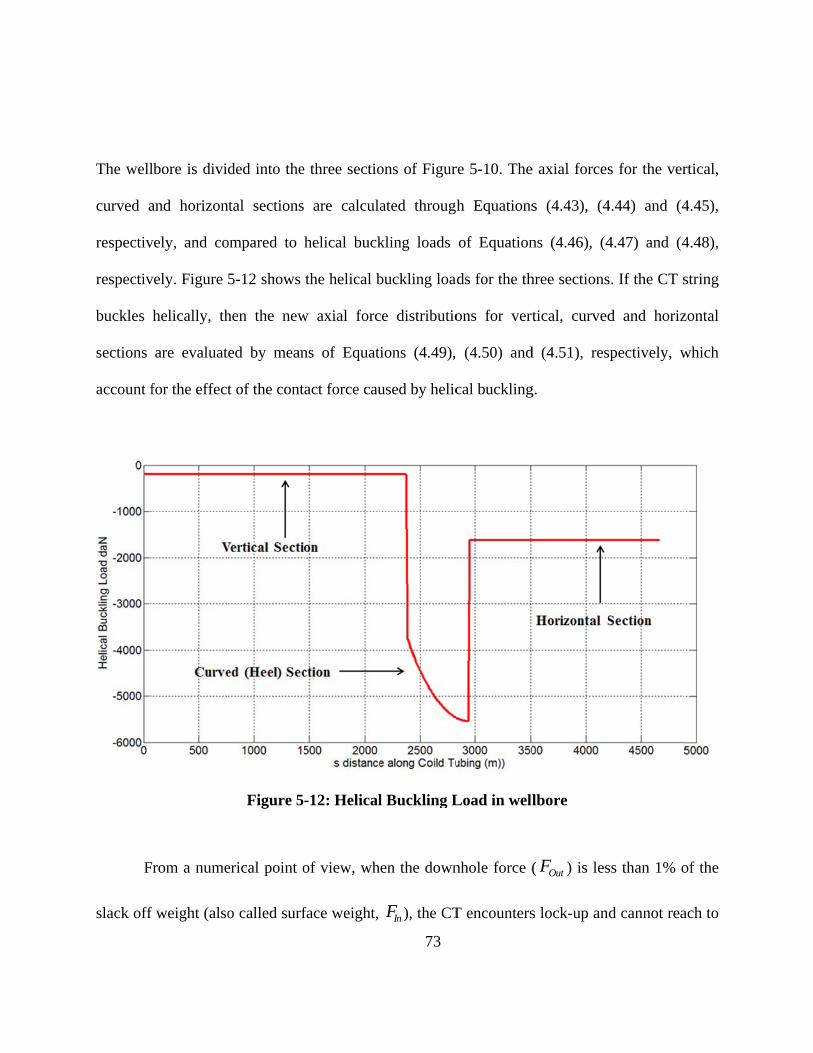
The well
curved a
respectiv
respectiv
buckles
sections
account f
F
slack off
lbore is divid
and horizon
vely, and co
vely. Figure
helically, th
are evaluat
for the effect
rom a nume
f weight (also
ded into the
ntal sections
ompared to
5-12 shows
hen the new
ed by mean
t of the cont
Figure 5
erical point o
o called surf
e three sectio
are calcula
helical buck
the helical b
w axial forc
ns of Equati
act force cau
-12: Helical
of view, wh
face weight,
73
ons of Figur
ated through
kling loads
buckling loa
ce distributio
ions ( 4.49),
used by helic
l Buckling L
en the down
InF ), the CT
re 5-10. The
h Equations
of Equation
ads for the th
ons for vert
( 4.50) and
cal buckling
Load in well
nhole force (
T encounters
e axial forces
s ( 4.43), ( 4
ns ( 4.46), ( 4
hree sections
tical, curved
d ( 4.51), res
g.
lbore
( OutF ) is les
s lock-up an
s for the ver
4.44) and ( 4
4.47) and ( 4
s. If the CT s
d and horiz
spectively, w
ss than 1% o
d cannot rea
rtical,
4.45),
4.48),
string
zontal
which
of the
ach to

the desir
transferre
once the
A
correspon
achieved
Then, the
weight c
iterations
could res
red depth. A
ed downhole
lock-up con
At first, the
nding slack
d after 127 ite
Figu
e CT string
calculation i
s. The Addi
sult in numer
Another Mat
e as a result
ndition is ach
CT string w
off weight c
erations.
ure 5-13: Sl
was run to
is shown in
ition of the
rical artifact
tlab program
of the slack
hieved.
was imagined
calculation i
lack off weig
the end of
n Figure 5-1
results for t
s in plot.
74
m was deve
off weight a
d to be run t
is shown in
ght calculat
the curved
14. The lock
the curved
eloped to ca
applied at th
to the end o
Figure 5-13
tion for vert
section and
k-up condit
section to th
alculate the
he surface. T
f the vertica
3. The lock-u
tical section
d the corresp
tion was ach
hose for the
amount of
he program
al section an
up condition
n
ponding slac
hieved after
e vertical se
force
stops
nd the
n was
ck off
r 144
ection
Fi
Finally, t
and the
condition
section c
show the
igure 5-14: S
the CT strin
correspondi
n was achiev
could result i
e trend of con
Slack off we
ng was run to
ing slack o
ved after 72
in numerical
nvergence.
eight calcul
o the end of
ff weight c
iterations. A
l artifacts in
75
ation for ve
f the horizon
calculation i
Again, exten
n the plot. A
ertical and c
ntal section
is shown in
nding the de
red dotted l
curved (heel
at a depth o
n Figure 5-
epth to inclu
line is used
l) sections
of 4565.92 m
15. The loc
ude the horiz
as a visual a
mMD
ck-up
zontal
aid to
Figu
N
Figure 5-
buckle to
re 5-15: Sla
Next, a mor
-16 for CT s
owards the en
ack off weig
re extended
string at a de
nd of the ver
ht calculati
depth is co
epth of 4584
rtical section
76
on for verti
onsidered. Th
4.91 mMD.
n and at the b
ical, curved
he axial com
The CT strin
beginning of
and horizo
mpressive fo
ng was pred
f the horizon
ontal section
force is show
dicted to heli
ntal section.
ns
wn in
ically

F
The plot
68 iterati
mMD. A
Figure 5-16:
of the slack
ions, which
A red dotted l
Axial Com
k off weight
implied tha
line is used a
pressive for
is shown in
at the CT str
as a visual ai
77
rce for CT s
Figure 5-17
ring can ind
id to show th
string at dep
7. The lock-u
deed reach t
he trend of c
pth of 4584.
up condition
the desired d
convergence
.91 mMD
n is achieved
depth of 458
.
d after
84.91

F
Figure 5-
of 4665.9
that helic
beginnin
CT that
drasticall
Figure 5-17
-18 reports t
92 mMD. F
cally buckle
g of horizon
attains heli
ly reduced.
7: Slack off w
the graph of
or the case
es comprises
ntal section.
ical bucklin
weight grap
f the axial co
of the longe
s more than
Because of
ng, the amo
78
ph for CT st
ompressive f
er reach (46
n half of the
the much lar
ount of forc
tring at dep
force for the
665.92 mMD
e length of
rger portion
ce transferre
th of 4584.9
e CT string d
D), the segm
the vertical
n of the verti
ed to the d
91 mMD
deployed at d
ment of CT s
l section an
cal section o
downhole en
depth
string
d the
of the
nd is

F
A
for the ca
is achiev
4665.92 m
Figure 5-18:
As it is expe
alculation of
ved (Figure
mMD.
Axial Com
ected from th
f the slack o
5-19). This
pressive for
he plot of the
off weight st
s means tha
79
rce for CT s
e axial comp
tops after on
at CT string
string at dep
pressive forc
nly 6 iteratio
g cannot rea
pth of 4665.
ce (Figure 5-
ons and the l
ach to the
.92 mMD
-18), the pro
lock-up cond
desired dep
ogram
dition
pth of
F
A
vibrating
2009), th
wellbore
model th
( _apprent h
plotted f
helically
Figure 5-19
As mentione
g tool (Agita
he applicatio
and string,
he effect o
helical ) of the
for the vibra
buckled sec
: Slack off w
ed above, a
ator). Based
on of a dow
which is in
f vibration,
e helically b
ating case, s
ctions both in
weight grap
a remedy fo
d on the expe
wnhole vibrat
nterpreted b
we use a
buckled sect
showing that
n the vertica
80
ph for CT st
or this prob
erimental da
ting tool res
y means of
value of
ion. In Figu
t the downh
l and the hor
tring at dep
blem is the
ata available
sults in a sm
f an apparen
0.185 for t
ure 5-20, the
hole vibratio
rizontal sect
th of 4665.9
application
e (Newmann
maller frictio
nt friction fa
the apparen
e axial com
on reduced t
tions of well
92 mMD
n of a down
n, 2007A, 20
on force bet
actor. In ord
nt friction f
mpressive for
the extent o
.
nhole
007B,
tween
der to
factor
rce is
of the

Figure
The calc
achieved
confirms
as a visua
5-20: Down
culation of t
d after 50 ite
that downh
al aid to sho
nhole Vibrat
the slack of
erations, whi
ole vibration
w the trend
tion Applica
ff weight is
ich means th
n is effective
of convergen
81
ation - Axia
s shown in
hat the CT s
e in extendin
nce.
al Compress
Figure 5-2
string can re
ng the CT re
sive force at
1. The lock
each to the d
ach. A red d
t 4665.92 m
k-up conditi
desired depth
dotted line is
MD
on is
h and
s used

Fig
gure 5-21: DDownhole Viibration Ap
82
pplication – Slack off wweight at 46665.92 mMD
83
Chapter 6. Summary and Recommendations
This thesis focused on the effect of downhole vibration in enhancing load transfer and
thus extending Coiled Tubing reach in a horizontal wellbore. Previous studies regarding different
aspects of buckling and of the effect of downhole vibration in Coiled Tubing intervention have
been reviewed in Chapter 2. In Chapter 3, we introduced: the surface equipment and downhole
tools which are required to perform Coiled Tubing intervention; the different types of CT well
intervention applications; the challenges and limitations which CT intervention requirements
encounter during design phase and operations; and the application of downhole vibration as a
remedy to these challenges. Chapter 4 introduced helical buckling load and axial load
distribution relations for vertical, curved and horizontal sections of a wellbore. These relations
have been extracted from the literature, as they are commonly used in the industry.
The core results of the thesis have been presented in Chapter 5. A modeling approach
has been introduced to explain the effect of vibration in enhancing load transfer using the
concept of apparent friction factors. The proposed model has been compared against the very
limited published experimental data available (Newman et al., 2007A, 2007B, 2009). In order to
show the effect of downhole vibration in extending the reach of a CT, two cases of CT
intervention have been modeled, namely with and without the application of downhole vibration.
The trend shows that, in the straight ad sinusoidal sections, the method of the multiple apparent
friction factors shows an improvement in the implementation of the relations proposed for the
buckled CT.

84
The effect of downhole vibration as a means to extend CT reach is a well-established
method in the oil and gas industry. Surface tests confirm the improvement of load transfer as a
result of vibration. A better understanding of downhole vibration in CT intervention and the
proposal of a modeling approach were the main objectives of this thesis. Considering the
information available in the public domain, this research was meant to add to the subject of
downhole vibration by means of a simple approach, which can describe the effect of downhole
vibration with a relatively small number of parameters.
Some subjects suggested as possible future research topics are
1. The design of further surface tests with actual sizes of CT strings in order to broaden the
available experimental data;
2. The study of the contact force due to the effect of vibration and the validation against
experimental data;
3. The development of a comprehensive vibration model for an entire wellbore.

85
References
Akgun, F. et al. (1996). Theoretical and Experimental Evaluation of Drill Pipe Stability
Conditions in Slim Holes. Society of Petroleum Engineers. doi:10.2118/37392-MS
Apostal, M. C. et al. (1990). A Study To Determine the Effect of Damping on Finite-Element-
Based, Forced-Frequency-Response Models for Bottomhole Assembly Vibration Analysis.
Society of Petroleum Engineers. doi:10.2118/20458-MS
Barakat, E. R. (2005). An Experimental Study and Modeling of the Effect of Hydraulic
Vibrations on Axial Force Transfer in Horizontal Wellbores. This report is prepared for TUDRP
Advisory Board Meeting Nov 14-15, 2005. Tulsa-Oklahoma
Barakat, E. R. et al. (2007). The Effect of Hydraulic Vibrations on Initiation of Buckling and
Axial Force Transfer for Helically Buckled Pipes at Simulated Horizontal Wellbore Conditions.
Society of Petroleum Engineers. doi:10.2118/105123-MS
Bernt S Aadnøy and Ketil Andersen (2001),"Design of oil wells using analytical friction
models", Journal of Petroleum Science and Engineering, Volume 32, Issue 1, 15 December
2001, Pages 53–71, doi:10.1016/S0920-4105(01)00147-4
Bhalla, K. (1994). Implementing Residual Bend in a Tubing Forces Model. Society of Petroleum
Engineers. doi:10.2118/28303-MS
86
Cheatham, J. B. and Pattillo, P. D. (1984). Helical Postbuckling Configuration of a Weightless
Column Under the Action of m Axial Load. Society of Petroleum Engineers. doi:10.2118/10854-
PA
Chen, Y. C. et al. (1989). An Analysis of Tubing and Casing Buckling in Horizontal Wells.
Offshore Technology Conference. doi:10.4043/6037-MS
Chen, Y. C., & Adnan, S. C. (1993). Buckling Of Pipe And Tubing Constrained Inside Inclined
Wells. Offshore Technology Conference. doi:10.4043/7323-MS
Chen, Y.-C. et al. (1990). Tubing and Casing Buckling in Horizontal Wells (includes associated
papers 21257 and 21308). Society of Petroleum Engineers. doi:10.2118/19176-PA
Cunha, J. C. (2003). Buckling of Tubulars Inside Wellbores: A Review on Recent Theoretical
and Experimental Works. Society of Petroleum Engineers. doi:10.2118/80944-MS
Dawson, R. and Paslay, P. R. (1984). Drill Pipe Buckling in Inclined Holes. Society of
Petroleum Engineers. doi:10.2118/11167-PA
Deli, G. et al. (1998). An Analysis of Helical Buckling of Long Tubulars in Horizontal Wells.
Society of Petroleum Engineers. doi:10.2118/50931-MS
Duman, O. B. et al. (2001). Effect of Tool Joints on Contact Force and Axial Force Transfer in
Horizontal Wellbores. Society of Petroleum Engineers. doi:10.2118/72278-MS
Gu, H. et al.(1993). Analysis of Slack-Off Force Transmitted Downhole in Coiled-Tubing
Operations. Society of Petroleum Engineers. doi:10.2118/26511-MS
87
Guo, B. et al. (2013). How Much Can You Extend the Reach of Coiled Tubing in Horizontal
Wells Using Pressure-Hammer/Pulsing Tools. Society of Petroleum Engineers.
doi:10.2118/164527-MS
Hammerlindl, D. J. (1980). Packer-to-Tubing Forces for Intermediate Packers. Society of
Petroleum Engineers. doi:10.2118/7552-PA
He, X., & Kyllingstad, A. (1995). Helical Buckling and Lock-Up Conditions for Coiled Tubing
in Curved Wells. Society of Petroleum Engineers. doi:10.2118/25370-PA
Heisig, G., & Neubert, M. (2000). Lateral Drillstring Vibrations in Extended-Reach Wells.
Society of Petroleum Engineers. doi:10.2118/59235-MS
Hishida, H. et al. (1996). Prediction of Helical / Sinusoidal Buckling. Society of Petroleum
Engineers. doi:10.2118/36384-MS
Kuru, E. et al.(1999). The Buckling Behavior of Pipes and Its Influence on the Axial Force
Transfer in Directional Wells. Society of Petroleum Engineers. doi:10.2118/52840-MS
Kwon, Y. W. (1988). Analysis of Helical Buckling. Society of Petroleum Engineers.
doi:10.2118/14729-PA
Li, Z. (1999a). Fundamental Equations for Dynamical Analysis of Rod and Pipe String in Oil
and Gas Wells. Society of Petroleum Engineers.
Li, Z. (1999b). Static Buckling of Rod and Pipe String in Oil and Gas Wells. Society of
Petroleum Engineers.
Love, A. E. H., (1944). “A Treatise on the Mathematical Theory of Elasticity”, Fourth Edition,
Dover Publications, New York, 1944

88
Lubinski, A. (1950)-A Study of the Buckling of Rotary Drilling Strings. American Petroleum
Institute.
Lubinski, A. et al. (1962). Helical Buckling of Tubing Sealed in Packers. Society of Petroleum
Engineers. doi:10.2118/178-PA
McCann, R. C., & Suryanarayana, P. V. R. (1994). Experimental Study Of Curvature And
Frictional Effects On Buckling. Offshore Technology Conference. doi:10.4043/7568-MS
McSpadden, A., & Newman, K. (2002). Development of a Stiff-String Forces Model for Coiled
Tubing. Society of Petroleum Engineers. doi:10.2118/74831-MS
Miska, S. et al. (1996). An Improved Analysis of Axial Force Along Coiled Tubing in
Inclined/Horizontal Wellbores. Society of Petroleum Engineers. doi:10.2118/37056-MS
Miska, S., & Cunha, J. C. (1995). An Analysis of Helical Buckling of Tubulars Subjected to
Axial and Torsional Loading in Inclined Wellbores. Society of Petroleum Engineers.
doi:10.2118/29460-MS
Mitchell, R. F. (1982). Buckling Behavior of Well Tubing: The Packer Effect. Society of
Petroleum Engineers. doi:10.2118/9264-PA
Mitchell, R. F. (1986a). Numerical Analysis of Helical Buckling. Society of Petroleum
Engineers. doi:10.2118/14981-MS
Mitchell, R. F. (1986b), Simple Frictional Analysis of Helical Buckling of Tubing, 13064-PA
SPE Journal Paper
Mitchell, R. F. (1988). New Concepts for Helical Buckling. Society of Petroleum Engineers.
doi:10.2118/15470-PA

89
Mitchell, R. F. (1995). Pull-Through Forces in Buckled Tubing. Society of Petroleum Engineers.
doi:10.2118/26510-PA
Mitchell, R. F. (1996). Comprehensive Analysis of Buckling With Friction. Society of Petroleum
Engineers. doi:10.2118/29457-PA
Mitchell, R. F. (2002). New Buckling Solutions for Extended Reach Wells. Society of Petroleum
Engineers. doi:10.2118/74566-MS
Mitchell, R. F. (2004). The Twist and Shear of Helically Buckled Pipe. Society of Petroleum
Engineers. doi:10.2118/87894-PA
Mitchell, R. F. (2006). The Effect of Friction on Initial Buckling of Tubing and Flowlines.
Society of Petroleum Engineers. doi:10.2118/99099-MS
Newman, K. et al. (2014). Extended Reach: Can We Reach Farther? Society of Petroleum
Engineers. doi:10.2118/168235-MS
Newman, K. R. (2004). Finite Element Analysis of Coiled Tubing Forces. Society of Petroleum
Engineers. doi:10.2118/89502-MS APA
Newman, K. R. et al. (2007, A).”Friction Reduction For Microhole CT Drilling”, Final Technical
Report, DOE Award Number: DE-FC26-05NT15485.
Newman, K. R. et al. (2007, B). “Vibration and Rotation Considerations in Extending Coiled-
Tubing Reach”, SPE paper 106979, SPE/ICoTA Coiled Tubing and Well Intervention
Conference and Exhibition, 20-21 March, The Woodlands, Texas, U.S.A., March 2007
Newman, K. R. et al. (2009). Modeling the Affect of a Downhole Vibrator. Society of Petroleum
Engineers. doi:10.2118/121752-MS

90
Oyedokun, O., & Schubert, J. (2014). Extending the Reach of Coiled Tubing in Directional
Wells With Downhole Motors. Society of Petroleum Engineers. doi:10.2118/168240-MS
Pabon, J. A. et al. (2010). Modeling Transient Vibrations While Drilling Using a Finite Rigid
Body Approach. Society of Petroleum Engineers. doi:10.2118/137754-MS
Paslay, P.R. and Bogy, D.B. (1964). The Stability of a Circular Rod Laterally Constrained to Be
in Contact With an Inclined Circular Cylinder. J. Appl. Mech. 31(4), 605-610 (Dec 01, 1964) (6
pages) doi:10.1115/1.3629721
Qiu, W. (1998). Prediction of Contact Force for Drill Pipe/Coiled Tubing. Society of Petroleum
Engineers. doi:10.2118/51092-MS
Qiu, W. et al. (1997). Effect of Coiled Tubing (CT) Initial Configuration on Buckling/Bending
Behavior in Straight Deviated Wells. Society of Petroleum Engineers. doi:10.2118/39003-MS
Qui, W. et al.(1998). Effect of Coiled Tubing Initial Configuration on Buckling Behavior in a
Hole of Constant Curvature. Society of Petroleum Engineers. doi:10.2118/46009-MS
Qui, W. et al. (1998). Drill Pipe/Coiled Tubing Buckling Analysis in a Hole of Constant
Curvature. Society of Petroleum Engineers. SPE-39795-MS
Qui, W. (1999). Effect of Drill Pipe/Coiled Tubing Initial Configuration on Contact Force.
Society of Petroleum Engineers. doi:10.2118/52189-MS
Salies, J. B. et al. (1994a). Experimental and Mathematical Modeling of Helical Buckling of
Tubulars in Directional Wellbores. Society of Petroleum Engineers. doi:10.2118/28713-MS
Salies, J. B. et al.(1994b). Experimental and Analytical Study of Sinusoidal Buckling in Vertical
Wells. Society of Petroleum Engineers. doi:10.2118/29164-MS

91
Sola, K.-I., & Lund, B. (2000). New Downhole Tool for Coiled Tubing Extended Reach. Society
of Petroleum Engineers. doi:10.2118/60701-MS
Sorenson, K. G. and Cheatham, J. B. (1986). Post-Buckling Behavior of a Circular Rod
Constrained Within a Circular Cylinder. J. Appl. Mech. 53(4), 929-934 (Dec 01, 1986) (6 pages)
doi:10.1115/1.3171883
Sun, C. & Lukasiewicz, S. (2006). A new model on the buckling of a rod in tubing. Journal of
Petroleum Science and Engineering, Volume 50, Issue 1, 16 January 2006, Pages 78-82, ISSN
0920-4105,
Terry, A. R. et al.(2004). Modeling Coiled Tubing Drag Forces - Small Factors Have a Big
Impact. Society of Petroleum Engineers. doi:10.2118/89598-MS
Tikhonov, V. et al. (2013). Dynamic Model for Stiff String Torque and Drag. Society of
Petroleum Engineers. doi:10.2118/163566-MS
Tikhonov, V. S. and Safronov, A. I.(2011). Analysis of Postbuckling Drillstring Vibrations in
Rotary Drilling of Extended-Reach Wells. J. Energy Resour. Technol. 133(4), 043102 (Dec 07,
2011) (8 pages) doi:10.1115/1.4005241
Walker, B.R. and Friedman, M.B.(1977). Three-Dimensional Force and Deflection Analysis of a
Variable Cross-Section Drillstring. J. Pressure Vessel Technol. 99(2), 367-373 (May 01, 1977)
(7 pages) doi:10.1115/1.3454543
Wicks, N. et al.(2012). Modeling of Axial Vibrations to Allow Intervention in Extended Reach
Wells. Society of Petroleum Engineers. doi:10.2118/156017-MS
92
Wu, J. (1995). Slack-off Load Transmission in Horizontal and Inclined Wells. Society of
Petroleum Engineers. doi:10.2118/29496-MS
Wu, J., & Juvkam-Wold, H. C. (1993a). Study of Helical Buckling of Pipes in Horizontal Wells.
Society of Petroleum Engineers. doi:10.2118/25503-MS
Wu, J., & Juvkam-Wold, H. C. (1993b), Helical Buckling of Pipes in Extended Reach and
Horizontal Wells—Part 1: Preventing Helical Buckling, J. Energy Resour. Technol 115(3), 190-
195 (Sep 01, 1993) (6 pages) doi:10.1115/1.2905992
Wu, J., & Juvkam-Wold, H. C. (1993c), Helical Buckling of Pipes in Extended Reach and
Horizontal Wells—Part 2: Frictional Drag Analysis, J. Energy Resour. Technol 115(3), 196-201
(Sep 01, 1993) (6 pages) doi:10.1115/1.2905993
Wu, J., & Juvkam-Wold, H. C. (1995a). Coiled Tubing Buckling Implication in Drilling and
Completing Horizontal Wells. Society of Petroleum Engineers. doi:10.2118/26336-PA
Wu, J. and Juvkam-Wold, H. C.(1995b). Buckling and Lockup of Tubulars in Inclined
Wellbores. J. Energy Resource. Technol. 117(3), 208-213 (Sep 01, 1995) (6 pages)
doi:10.1115/1.2835342
Wu, J. and Juvkam-Wold, H. C.(1995c). The Effect of Wellbore Curvature on Tubular Buckling
and Lockup. J. Energy Resource. Technol. 117(3), 214-218 (Sep 01, 1995) (5 pages)
doi:10.1115/1.2835343
Zhang, Y. L. (1989). A Study of Helical Buckling of the Compressed Portion of a Drillstring
During Straight-Hole Drilling Using a Down-hole Motor. Society of Petroleum Engineers.

93
Appendix A Force-Pitch Relationship
In this appendix, the force-pitch relationship for a long, weightless string subjected to
compressive force is reported, based on the work by Lubinski et al. (1962).
Assuming linear elasticity, the length cL of the string subjected to compressive force F is
1 acL L
E
, (A-1)
where a is average axial stress and E is the Young’s modulus.
The length of the helix hL (measured along its axis) is
2 2 24c
h
L pL
p r
,
(A-2)
where p is pitch of the helix and r is the tubing-to-casing radial clearance.
The strain energy for axial compression is
Uc
1
2
L
EAs
Fa
2 , (A-3)
where
sinaF F , (A-4)
and
2 2sin
4
p
p r
.
(A-5)
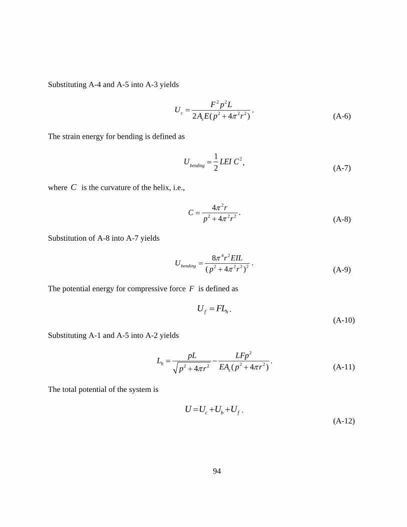
94
Substituting A-4 and A-5 into A-3 yields
2 2
2 2 22 ( 4 )cs
F p LU
A E p r
.
(A-6)
The strain energy for bending is defined as
Ubending
1
2LEI C 2 ,
(A-7)
where C is the curvature of the helix, i.e.,
2
2 2 2
4
4
rC
p r
. (A-8)
Substitution of A-8 into A-7 yields
4 2
2 2 2 2
8
( 4 )bending
r EILU
p r
. (A-9)
The potential energy for compressive force F is defined as
f hU FL .
(A-10)
Substituting A-1 and A-5 into A-2 yields
2
2 22 2 ( 4 )4h
s
pL LFpL
EA p rp r
.
(A-11)
The total potential of the system is
c b fU U U U .
(A-12)
95
Substitution of A-6, A-9 and A-10 into A-12 yields
2 2 4 2
2 2 2 2 2 2 2 2 2 2
8
2 ( 4 ) ( 4 ) 4s
F p L r EIL FpLU
A E p r p r p r
. (A-13)
The condition of equilibrium is calculated by minimizing the total potential energy of the system
with respect to the pitch of the helix, i.e.:
dU dp 0.
(A-14)
Applying condition A-14 to A-13 yields
32 2 22 2 2 2 22
( 4 )( 4 ) 8 0
s
p p rF p r F EIp
A E
.
(A-15)
Solving for the smallest root (corresponding to the smallest total energy) in A-15 for F yields:
2 2 2 2 2
2 2 2 2
4 321 1
2 ( 4 )s
s
A E p r IpF
p A p r
.
(A-16)
Considering the ratio of the length of the string to the radial clearance between the string and the
wellbore, in oil and gas applications the following assumption holds
2p >> 2 24 r . (A-17)
For a << 1, the first-order Taylor expansion of the square root can be used:
1 a 1 (a / 2).
(A-18)
Applying A-17 and A-18 to A-16 yields:

96
2
2
8 EIF
p
.
(A-19)
Appendix B Sinusoidal Buckling Load
In this appendix, the equations for the sinusoidal buckling load are reported, based on
the works by Paslay and Bogy (1964) and Dawson and Paslay (1984). The buckling initiation
force for a pipe in horizontal wellbore is given by
2 2 42
2 2 4
1
1 1 2crit
L AgF EI n
L n EIr
.
(B-1)
The weight per unit length of pipe is
w Ag .
(B-2)
Substituting B-2 and assuming the typical Poisson’s ratio for steel ( 0.3) yields
2
2 2 4
2 2 2 4crit
L wF EI n EI
L L n EIr
, (B-3)
which can be rearranged as
2 2
crit
n w LF EI
L r n
.
(B-4)
B-4 results from an eigenvalue problem (Paslay and Bogy, 1964) where n is the order of
buckling that occurs in a pipe length of L. Considering a long pipe and treating n as a continuous
variable, the minimum value of critF is obtained by imposing
97
0critF
n
.
(B-5)
Applying condition B-5 to B-4 yields
n2 L4w
4EIr. (B-6)
Substituting B-6 into B-4 yields
2crit
EIwF
r ,
(B-7)
where critF is the required compressive force for the pipe to transition to the sinusoidal
configuration in a horizontal wellbore.
For an inclined wellbore with inclination angle of , the distributed load due to the weight of the
pipe, in the direction orthogonal to the pipe is
sinw Ag ,
(B-8)
Replacing B-8 into B-7 yields
sin
2crit
EI AgF
r
,
(B-9)
where critF is the required compressive force for the pipe to transition to the sinusoidal
configuration in an inclined wellbore.

98
Appendix C Helical Buckling Load
In this appendix, the equations for the helical buckling load are reported, based on the
works by Cheatham and Pattillo (1984) and Chen et al. (1989).
The strain energy for bending is defined as:
Ubending
1
2LEI C 2 ,
(C-1)
where C is the curvature of the helix, i.e.,
2
2 2 2
4
4
rC
p r
. (C-2)
Applying C-2 into C-1 yields
4 2
2 2 2 2
8
( 4 )bending
r EILU
p r
. (C-3)
The number of full waves in a buckled pipe ( m ) is
L
mp
. (C-4)
In oil and gas applications the following assumption holds
2p >> 2 24 r . (C-5)
Substituting C-4 and C-5 into C-3 yields

99
Ub
8 4EILr 2
(L m)4.
(C-6)
The work done by the external axial force F is:
( )e c zW F L L ,
(C-7)
where cL is the length of the compressed pipe prior to buckling and zL is the length of the helix
measured along its axis.
Considering the geometry of the helix, we have that
sinc zL L L L ,
(C-8)
and
2 2sin
4
p
p r
.
(C-9)
For a << 1, the first-order Taylor expansion of the square root can be used:
1 a 1 (a / 2).
(C-10)
Substituting C-4, C-5, C-8, C-9 and C-10 into C-7 yields
We
2FL 2r 2
(L m)2.
(C-11)
The change in potential energy when the pipe transitions from straight to helical shape, with the
center of gravity at the center of the hole is
V wLr ,
(C-12)

100
where r is the radial clearance between pipe and wellbore wall.
Conservation of energy law requires
e bW U V .
(C-13)
Substituting C-6, C-11 and C-12 into C-13 yields
2FL 2r 2
(L m)2
8 4EILr 2
(L m)4 wLr .
(C-14)
Solving the C-14 with respect to F yields the helical buckling force
2 2* 4
2
m w LF EI
L r m
. (C-15)
Now, by minimizing the helical buckling force *F with respect to number m of full waves in the
buckled rod, i.e.,
*
0F
m
,
(C-16)
the value of m is obtained as
22
8
w Lm
rEI
. (C-17)
Substituting C-17 into C-15 finally yields
* 2 2EIw
Fr
. (C-18)
Related Documents