IOP PUBLISHING JOURNAL OF PHYSICS D: APPLIED PHYSICS J. Phys. D: Appl. Phys. 42 (2009) 105503 (13pp) doi:10.1088/0022-3727/42/10/105503 Effect of discretization of permeability term and mesh size on macro- and meso-segregation predictions Arvind Kumar, Bernard Dussoubs, Miha Zaloˇ znik and Herv´ e Combeau 1 Institut Jean Lamour, D´ epartement SI2M, CNRS - Nancy-Universit´ e - UPV-Metz, Ecole des Mines de Nancy, Parc de Saurupt CS 14234, F-54042 Nancy cedex, France E-mail: [email protected] Received 4 November 2008, in final form 26 March 2009 Published 28 April 2009 Online at stacks.iop.org/JPhysD/42/105503 Abstract The effect of interpolation schemes used for discretization of permeability in numerical simulations on macrosegregation and channel segregation (mesosegregation) during solidification has been studied. The different ways to discretize the permeability term and its effect on the interdendritic velocity are illustrated by a simplified 1D model which solves the Darcy equation for a porous medium. The Darcy equation is solved numerically using the SIMPLE algorithm for the coupled velocity–pressure fields. For this simplified case, an analytical reference solution can also be obtained. In the numerical solution four different interpolation schemes for permeability discretization have been employed, and the results obtained are compared. For coarse mesh, different interpolation schemes produce large differences from the analytical reference solution. We thereafter, present simulation results for solidification of Sn–Pb alloy in a two-dimensional rectangular cavity using different discretization schemes. It is observed that solute-rich liquid flowing towards the bottom of the rectangular cavity in the mushy zone due to thermosolutal convection results in patches of thin structure known as channels. These channels are formed by perturbation by the interdendritic fluid flow in the mushy zone and in some cases by the localized remelting in some portions of the solid/mush interface. The role of discretization schemes and mesh size on the formation of channel segregates and macrosegregation is discussed. (Some figures in this article are in colour only in the electronic version) Nomenclature C average mass fraction of solute (Pb) (wt%) C 0 initial mass fraction of solute (Pb) in the alloy (wt%) c p specific heat (J kg −1 K −1 ) D solutal diffusion coefficient (m 2 s −1 ) g l volume fraction of liquid g gravity vector (m s −2 ) GM global macrosegregation h enthalpy (J kg −1 ) k thermal conductivity (W m −1 K −1 ) 1 Author to whom any correspondence should be addressed. k p binary partition coefficient K permeability (m 2 ) L latent heat of fusion (J kg −1 ) l length of the domain (m) m L liquidus slope ( ◦ C wt% −1 ) p pressure (Pa) t time (s) T temperature ( ◦ C) v superficial average velocity (m s −1 ) v l intrinsic velocity of the liquid phase (m s −1 ) v T velocity of the isotherm (m s −1 ) V volume (m 3 ) V domain volume of the computational domain (m 3 ) X, Y coordinate axes (m) 0022-3727/09/105503+13$30.00 1 © 2009 IOP Publishing Ltd Printed in the UK

Welcome message from author
This document is posted to help you gain knowledge. Please leave a comment to let me know what you think about it! Share it to your friends and learn new things together.
Transcript
IOP PUBLISHING JOURNAL OF PHYSICS D: APPLIED PHYSICS
J. Phys. D: Appl. Phys. 42 (2009) 105503 (13pp) doi:10.1088/0022-3727/42/10/105503
Effect of discretization of permeabilityterm and mesh size on macro- andmeso-segregation predictionsArvind Kumar, Bernard Dussoubs, Miha Zaloznik and Herve Combeau1
Institut Jean Lamour, Departement SI2M, CNRS - Nancy-Universite - UPV-Metz, Ecole des Mines deNancy, Parc de Saurupt CS 14234, F-54042 Nancy cedex, France
E-mail: [email protected]
Received 4 November 2008, in final form 26 March 2009Published 28 April 2009Online at stacks.iop.org/JPhysD/42/105503
AbstractThe effect of interpolation schemes used for discretization of permeability in numericalsimulations on macrosegregation and channel segregation (mesosegregation) duringsolidification has been studied. The different ways to discretize the permeability term and itseffect on the interdendritic velocity are illustrated by a simplified 1D model which solves theDarcy equation for a porous medium. The Darcy equation is solved numerically using theSIMPLE algorithm for the coupled velocity–pressure fields. For this simplified case, ananalytical reference solution can also be obtained. In the numerical solution four differentinterpolation schemes for permeability discretization have been employed, and the resultsobtained are compared. For coarse mesh, different interpolation schemes produce largedifferences from the analytical reference solution. We thereafter, present simulation results forsolidification of Sn–Pb alloy in a two-dimensional rectangular cavity using differentdiscretization schemes. It is observed that solute-rich liquid flowing towards the bottom of therectangular cavity in the mushy zone due to thermosolutal convection results in patches of thinstructure known as channels. These channels are formed by perturbation by the interdendriticfluid flow in the mushy zone and in some cases by the localized remelting in some portions ofthe solid/mush interface. The role of discretization schemes and mesh size on the formation ofchannel segregates and macrosegregation is discussed.
(Some figures in this article are in colour only in the electronic version)
Nomenclature
C average mass fraction of solute (Pb) (wt%)C0 initial mass fraction of solute (Pb) in the alloy (wt%)cp specific heat (J kg−1 K−1)D solutal diffusion coefficient (m2 s−1)gl volume fraction of liquidg gravity vector (m s−2)GM global macrosegregationh enthalpy (J kg−1)k thermal conductivity (W m−1 K−1)
1 Author to whom any correspondence should be addressed.
kp binary partition coefficientK permeability (m2)L latent heat of fusion (J kg−1)l length of the domain (m)mL liquidus slope (◦C wt%−1)p pressure (Pa)t time (s)T temperature (◦C)v superficial average velocity (m s−1)vl intrinsic velocity of the liquid phase (m s−1)vT velocity of the isotherm (m s−1)V volume (m3)Vdomain volume of the computational domain (m3)X, Y coordinate axes (m)
0022-3727/09/105503+13$30.00 1 © 2009 IOP Publishing Ltd Printed in the UK
J. Phys. D: Appl. Phys. 42 (2009) 105503 A Kumar et al
Greek symbols
βT thermal expansion coefficient (◦C−1)βc solutal expansion coefficient (wt%−1)λ2 secondary dendrite arm spacing (m)µ dynamic viscosity (kg m−1 s−1)ρ mass density (kg m−3)
Subscripts
0 referencel liquidm melting point for a pure substances solid
1. Introduction
For alloys solidifying with columnar microstructure, a diffusezone of porous crystalline solid (mushy zone) separates themelt from the fully solidified region, and coupled fluid flow,induced by buoyancy forces, solidification shrinkage, etc,occurs in the mush and the melt. The mushy zone isthe source of all important phenomena such as macro- andmicrosegregation, as-cast mechanical properties and porosity.Macrosegregation in castings refers to variations in the averagecomposition of alloying elements at the scale of casting.Fluid flow in the mushy zone plays an important role in theformation of macrosegregation in the castings by redistributingthe segregated solute elements [1–5] and in some casesforms channel segregates in the mushy zone [6–9]. Theformation of channel segregates in castings represents a severeform of segregation, also known as mesosegregation, sincethe composition and crystalline structure of the solid whichultimately forms within the channels differ significantly fromthose of the nearby solid regions. Mesosegregations in thecasting appear as long narrow trails aligned in some preferreddirection, with solute concentration greater than that of thesurrounding regions. The mesosegregates are formed dueto interdendritic flow in the two-phase region (solid/liquid)during the solidification process. The interdendritic fluidflow leads to perturbations of the growing columnar structure.The instability of the growth front leads to further instabilityof the segregation map leading to the formation of channelsegregates. The scale of mesosegregation can affect thehomogenization of the ingot and its extent in the casting canseverely influence the quality of ingots.
Macrosegregation has been widely studied usingmultiscale models consisting of macroscopic models based onmixture theory [2] or volume averaging [10], coupled to modelsof microsegregation [11]. In the volume-averaged formulation,generally, the equations are solved on a representative elementvolume (REV), small with respect to the extent of the mushyzone, but large compared with the dendrite arm spacing(DAS). The averaging method allows us to use a single setof equations in the whole domain (fully liquid, mushy zoneand fully solid). In this representation, the mushy zoneis considered as a saturated porous medium with varyingpermeability and the flow in the mushy zone is governedby the Darcy law. Models relating the permeability to the
liquid fraction, e.g. the Carman–Kozeny model, are generallyused to calculate the permeability. The solution proceduresof these macroscopic models involve the discretization ofthe macroscopic conservation equations based most ofteneither on a finite-volume formulation [1–6] or on a finite-element formulation [6, 12–15]. In these formulations, aset of governing equations, characterizing the transport andconservation of mass, energy, momentum and solute in theingot, is solved at the macroscopic scale, which gives theevolutions in time of different averaged parameters, such asvelocity, temperature and solute concentration.
One of the parameters that has an essential effecton macrosegregation profiles is the mush permeability.Permeability in the mushy zone, which for the simplest modelis a function of the liquid fraction and of the dendritic armspacing (DAS), varies over a wide range of magnitude fora variation of liquid fraction from 1 to 0. In the melt,the liquid fraction is equal to one and the permeability isinfinite. Accordingly, as solidification completes, liquidfraction and permeability tend towards zero. The dependenceof permeability on liquid fraction is highly nonlinear, thusa small variation in the liquid fraction can result in a largevariation in permeability which can significantly affect the flowin the mushy zone and hence the segregation pattern. Withina volume-averaged solidification model the permeability isthe principal parameter of the Darcy term, which describesthe hydrodynamic drag of the porous mush in the averagedmomentum balance equation. In the finite-volume formulationthe discretization of the momentum balance equation requiresan estimation of the volume integral of the Darcy termover the control volume (CV)
∫V
gl(µ/K)v dV by applyingsome discretization scheme. The way this integration isapproximated to get the discretized form of the Darcy term canplay an important role in the numerical predictions [16]. Thepermeability (K) is a function of the liquid fraction (gl) and isthus known at the CV nodes. When using staggered pressure–velocity grids the Darcy term has to be integrated over thevelocity CV using some interpolation of the permeability fromthe adjacent pressure CVs.
To the best of our knowledge, the effect of the numericaldiscretization of the Darcy term on the predictions of macro-and mesosegregation has not been investigated in the literature.The objective of this paper is to investigate the effect ofdiscretization schemes for the permeability term on predictionsof macrosegregation and channel segregates in the mushyregion. In this respect, two important aspects of thenumerical studies aimed at predicting channel segregatesrequire special attention; (a) does a good resolution for theprediction of channel segregates depend on the discretizationof permeability and (b) does this depend on mesh size usedin computations. To answer these questions, simulationsusing different discretization schemes are performed in thisstudy for solidification of an alloy in a side-cooled cavity.Using the Carman–Kozeny relation to express permeability,we have employed different discretizations of the Darcyterm: (a) linear interpolation of the permeability between twoadjacent cells, (b) harmonic mean of the permeability betweentwo adjacent cells, (c) volume weighted interpolation of the
2
J. Phys. D: Appl. Phys. 42 (2009) 105503 A Kumar et al
liquid fraction between two adjacent cells and computationof the permeability with the interpolated value of the liquidfraction and (d) analytical integration of the Darcy termassuming a linear variation of gl between the adjacent pressurepoints. The paper is organized as follows. We first introducethe volume-averaged micro-macroscopic solidification model.Then we present the different integration schemes that weused for the Darcy term. We analyse the accuracy of thedifferent discretization schemes in predicting the interdendriticvelocity in the mushy zone by solving the Darcy equationon a simplified 1D problem and comparing the numericalsolutions with the analytical solution. This analysis enablesus to observe the behaviour of various discretization schemeswhich will be helpful in analysing results obtained in 2Dsimulations. Thereafter, we present simulation results fora 2D solidification case and discuss the effects of variousdiscretization schemes and of the mesh size on the predictionof macro- and mesosegregation.
2. Mathematical modelling
The conservation equations for solidification in a 2Drectangular cavity involve the following main assumptions:
(a) The liquid flow is laminar and Newtonian. The viscosity µ
is constant. The solid phase is fixed and non-deformable.(b) The solidifying system is considered to be a two-phase
system, of either solid or liquid. Gas porosity is neglected.
gs + gl = 1. (1)
(c) The mushy zone is modelled as a porous medium saturatedwith liquid. The permeability is defined through Carman–Kozeny relation [17]:
K = λ22g
3l
180(1 − gl)2. (2)
(d) Solid and liquid mass densities are equal and constantexcept for the buoyancy term in the momentumconservation equation, where the density of theliquid depends on temperature and solute concentration(Boussinesq approximation):
ρl(T ,Cl) = ρ0[1 − βT(T − T0) − βc(Cl − C0)]. (3)
(e) Microsegregation obeys the following hypotheses: infinitediffusion in the liquid, zero diffusion in the solid andthermodynamic equilibrium at the solid–liquid interfaceduring solidification. In the case of a closed system,where the average concentration remains constant, theseassumptions correspond to the Scheil law. In the case ofan open system, a specific treatment has to be done. Inthis model for each CV, which is considered locally as anopen system (i.e. its overall solute content can be modifiedby macroscopic transport), the average mass fraction ofsolute in the solid phase can be expressed as
Cs = 1
gs
∫ gs
0Cs(α) dα = 1
gs
∫ gs
0C∗
s (gs) dgs, (4)
where Cs is the concentration profile in the solid, C∗s is
the concentration of the solid phase at the solid–liquidinterface. In the absence of solid diffusion the profile ofthe concentration in the solid remains frozen and is givenby the interface concentration along the solidification path,C∗
s (gs). The average solid concentration Cs is thus theaveraged integral of this concentration profile. Duringsolidification the interface composition in the solid phaseC∗
s is related to the liquid composition at the interfaceC∗
l , assuming that the interface is at thermodynamicequilibrium
C∗s = kpC∗
l . (5)
The average liquid composition Cl is assumed always tobe equal to C∗
l due to infinitely fast diffusion of solute atthe microscopic scale
Cl = C∗l . (6)
In the case of remelting the interface condition is different[11]. In order to consider remelting we followed theideas of Rappaz and Voller [11], which were also usedby Heinrich and Poirier [18] and Kumar et al [19]. Sincethe concentration profile in the solid remains frozen dueto the absence of diffusion, we have to remelt whathas been solidified, so the condition is taken from themicrosegregation profile in the solid
C∗s = Cs(α = gs). (7)
Thus, in the case of remelting, the condition in equation (7)is applied instead of the equilibrium condition ofequation (5). The concentration profile in the solid Cs
(α) has to be stored for this purpose.(f) The phase diagram is linearized (with a constant liquidus
slope). Taking into account the infinite diffusion in theliquid phase (equation (6)) the temperature can be thusexpressed as
T = Tm + mLC∗l = Tm + mLCl. (8)
(g) The relationship between average enthalpy, temperatureand volume fraction of solid, assuming constant and equalcp for solid and liquid phase, can be expressed as
h = gshs + (1 − gs)hl = cp(T − T0) + (1 − gs)L. (9)
The conservation equations for mass, heat and solute areaveraged over both liquid and solid phase and are given asfollows [4, 6]:
Mass conservation:
∇ · v = ∇ · (glvl) = 0. (10)
Energy conservation:
ρ∂h
∂t+ ρcpv · ∇T = ∇ · (k∇T ). (11)
3
J. Phys. D: Appl. Phys. 42 (2009) 105503 A Kumar et al
Solute conservation:
ρ∂C
∂t+ ρ v · ∇Cl = ∇ · (ρD∇Cl). (12)
Due to the small diffusion coefficient D, the diffusionterm is often considered negligible in equation (12), whichreduces it to
ρ∂C
∂t+ ρ v · ∇Cl = 0. (13)
Momentum conservation for the liquid phase [20]:
ρ∂v
∂t+
ρ
glv · (∇v) = µ∇2 v − gl
µ
Kv
+ ρ0[βT(T − T0) + βc(Cl − C0)]glg − gl∇p. (14)
The momentum conservation equation is written using theaveraging technique presented in [6]. The term gl(µ/K)v
corresponds to a drag force of the solid skeleton on theinterdendritic liquid region. In this work the focus is onthe evaluation of this term using different discretizationschemes, to be discussed in section 2.1. The governingtransport equations have been solved using the finite-volumetechnique [21] with a staggered grid arrangement. In thisformulation, the computational domain is divided into non-overlapping control volumes. All scalar variables (enthalpy,temperature, pressure, etc) are computed at the centre of thepressure CVs, while a staggered grid is used to determine thecomponents of the velocity at the faces of the pressure CVs.The SIMPLE algorithm [22] is used to treat the pressure–velocity coupling. A specific algorithm, detailed in [4, 6] hasbeen implemented in order to resolve the nonlinearity of thetransport equations, and in particular the relationship betweentemperature and enthalpy. The phase change that is governedby the coupling of heat and mass transfer and thermodynamicequilibria at the microscopic scale is introduced by solving thesystem of equations (1), (4)–(6) and (8)–(9) for solidificationand equations (1), (4) and (6)–(9) for remelting locally ineach meshpoint. Given the average enthalpy h and averageconcentration C = gsCs + glCl, which are obtained from themacroscopic conservation equations (11) and (13), the solutionof the microscopic system gives the temperature T , the phaseconcentrations Cs and Cl, the phase fractions gs and gl andthe interface concentrations C∗
s . To account for the case ofremelting, the concentration profile in the solid phase has tobe kept in memory, as already explained (equation (7)). Toavoid excessive storage, the profile is stored at increments of�gs = 0.01, which gives sufficient precision [19]. Linearinterpolation is used to compute the profile between the storedpoints during remelting.
2.1. Discretization of the permeability term
In the mushy zone the only significant forces of the momentumbalance are the Darcy drag, the pressure gradient and thebuoyancy. This reduces the momentum equation (14) to
− µ
Kv + ρ0[βT(T − T0) + βc(Cl − C0)]g − ∇p = 0. (15)
Due to the strong nonlinear dependence of the permeability K
on the liquid fraction gl the discretization of the Darcy termis critical for the accuracy of the numerical solution of theflow in the mushy zone. To get the discretized form of thisterm we have to approximate its integral across the controlvolume
∫V(µ/K)v dV . For the horizontal component of the
momentum equation this means integration between the faces‘w’ and ‘e’ of the velocity CV ‘P’, which corresponds to theadjacent pressure points. This gives
∫ e
w(µ/K) vxS dx, where
S is the cross section of the CV. We point out that in all schemeswe approximate the velocity to be constant across the wholevelocity CV. Further, we recall that the viscosity µ is assumedto be constant. This means that the integral is evaluated as∫ e
w
(µ/K)vxS dx = µvx,P S
∫ e
w
dx
K= µvx,P S
1
KP, (16)
where KP is the effective discretized value of the permeabilityin CV ‘P’ that is evaluated using an approximation of theintegral
∫ e
wdx/K by some interpolation of K between the
faces ‘w’ and ‘e’, where it is known. We now introduce fourdifferent discretization schemes for the approximation of thisintegral using different ways of interpolating K between thetwo adjacent pressure points.
(a) Linear interpolation of the permeability between twoadjacent cells.
(b) Harmonic mean of the permeability between two adjacentcells.
(c) Volume weighted interpolation of the liquid fractionbetween two adjacent cells and computation of thepermeability with the interpolated value of the liquidfraction.
(d) Analytical integration of the Darcy term assuming a linearvariation of gl between the adjacent pressure points.
1
KP=
∫ e
w
dx
K(gl(x)). (17)
The dependence of the permeability on the liquid fractionK(gl) is given by equation (2) and the variation of the liquidfraction gl(x) is assumed to be linear between the adjacentpressure points ‘w’ and ‘e’.
2.2. Simplified 1D problem
To evaluate the accuracy of the proposed discretizationschemes for permeability we consider a problem of 1D flowin the mushy region by solving the Darcy equation. We solvethe problem numerically using these schemes and comparethe results with the analytical solution of this problem. In themushy zone the inertial and viscous terms of the momentumequation (14) can be neglected. Considering a horizontalorientation also omits the buoyancy term. We obtain the Darcymomentum equation.
µ
Kv = −dp
dx. (18)
There are two unknowns in equation (18), velocity (v) andpressure (p). The second equation necessary to close the
4
J. Phys. D: Appl. Phys. 42 (2009) 105503 A Kumar et al
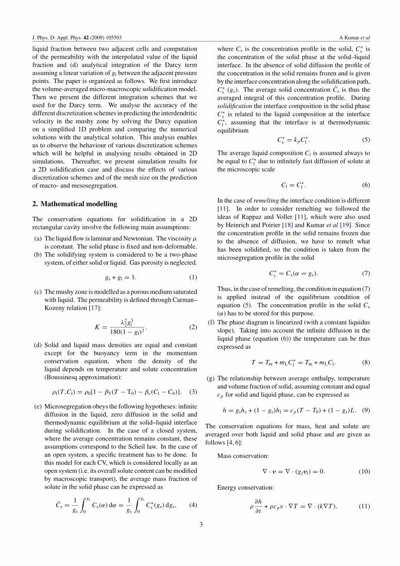
Figure 1. Schematic representation of the 1D problem. Scheil solidification path is used for variation of liquid fraction (gl) along the length.
system is the continuity equation:
dv
dx= 0. (19)
This typically shows the fluid flow in a 1D mushy region drivenby the imposed pressure gradients. For the simplified 1Dproblem, described by equations (18) and (19), an analyticalsolution, detailed below, can also be obtained. Combiningequations (18) and (19), we obtain
d
dx
(K
µ
dp
dx
)= 0. (20)
Equation (19) depicts that velocity is constant across the 1Ddomain. As a consequence, given an inlet pressure (pin) and anoutlet pressure (pout) in a domain of length l, and consideringa constant dynamic viscosity µ, the pressure profile can beexpressed as
p = Aµ
∫ x
0
dx
K(x)+ pin, (21a)
where A is a constant of integration given as
A = (pout − pin)
(µ
∫ l
0
dx
K(x)
)−1
. (21b)
The permeability, as defined in equation (2) depends on thesecondary DAS (λ2) (considered as constant in this work) andon the liquid fraction (gl). Given a profile of liquid fractionin the domain, it is possible to determine the permeability as afunction of x, and then pressure using equation (21a). It maybe noted that expressions in equation (21a) can be calculatedanalytically. Once the pressure is determined the velocity canbe calculated using equation (18). The same problem is alsosolved numerically using the discretization schemes describedin section 2.1. In the numerical solution the same methodologyis followed as explained for the full model.
3. Results and discussion
3.1. Simplified 1D problem
Figure 1 shows a schematic for the 1D problem consideredand the parameters used for the computation are given intable 1. The problem consists of flow in a 1D domain drivenby imposed pressure gradient between the inlet and the outlet.In this problem we solve only the fluid flow and the problemis not coupled to macrosegregation. The domain depicts the
Table 1. Thermophysical data and parameters used in the 1Dcomputation.
Parameter Scheil solidification path
Phase diagramInitial mass fraction (wt%) 5.0Melting temperature (◦C) 232.0Liquidus slope (◦C wt%−1) −1.286Partition ratio 6.56 × 10⁻²
Thermophysical dataMolecular viscosity (kg m−1 s−1) 10−3
Secondary DAS (µm) 50.0
Computational parametersLength of the domain (m) 0.1Liquid fraction at inlet 0.99Liquid fraction at outlet 0.6Pressure drop in the domain (Pa) −2000Temperature gradient (K m−1) −39.4
mushy region with liquid fraction varying from 0.99 to 0.6on a distance of 10 cm. This range of liquid fraction inthe mushy domain is chosen so that the magnitude of theinterdendritic fluid velocity in the domain is significant. Asmacrosegregation is neglected, the Scheil law can be usedto relate the average solute concentration in the liquid tothe liquid fraction as Cl = C0g
(kp−1)
l . Then, substitutingfrom equation (8) for Cl in the Scheil law, one can get theliquid fraction as a function of temperature, which can besimplified to gl = [(T −Tm)/(mLC0)](1/(kp−1)). The variationof the liquid fraction in the domain is deduced assuming aconstant composition (C0 = 5 wt%Pb) and a linear variationof temperature with a given inlet temperature and temperaturegradient (see figure 1), T (x) = 225.57 ◦C + ∇T · x, where∇T = −39.4 ◦C m−1. A small temperature gradient acrossthe domain is chosen to have a wider mushy zone so thatwe can emphasize the effect of discretization schemes forpermeability on the interdendritic flow in the mushy zone.The imposed pressure drop (�p) is chosen such that fluidvelocities are of the order typically encountered in a liquidmetal flow (∼10−3 m s−1).
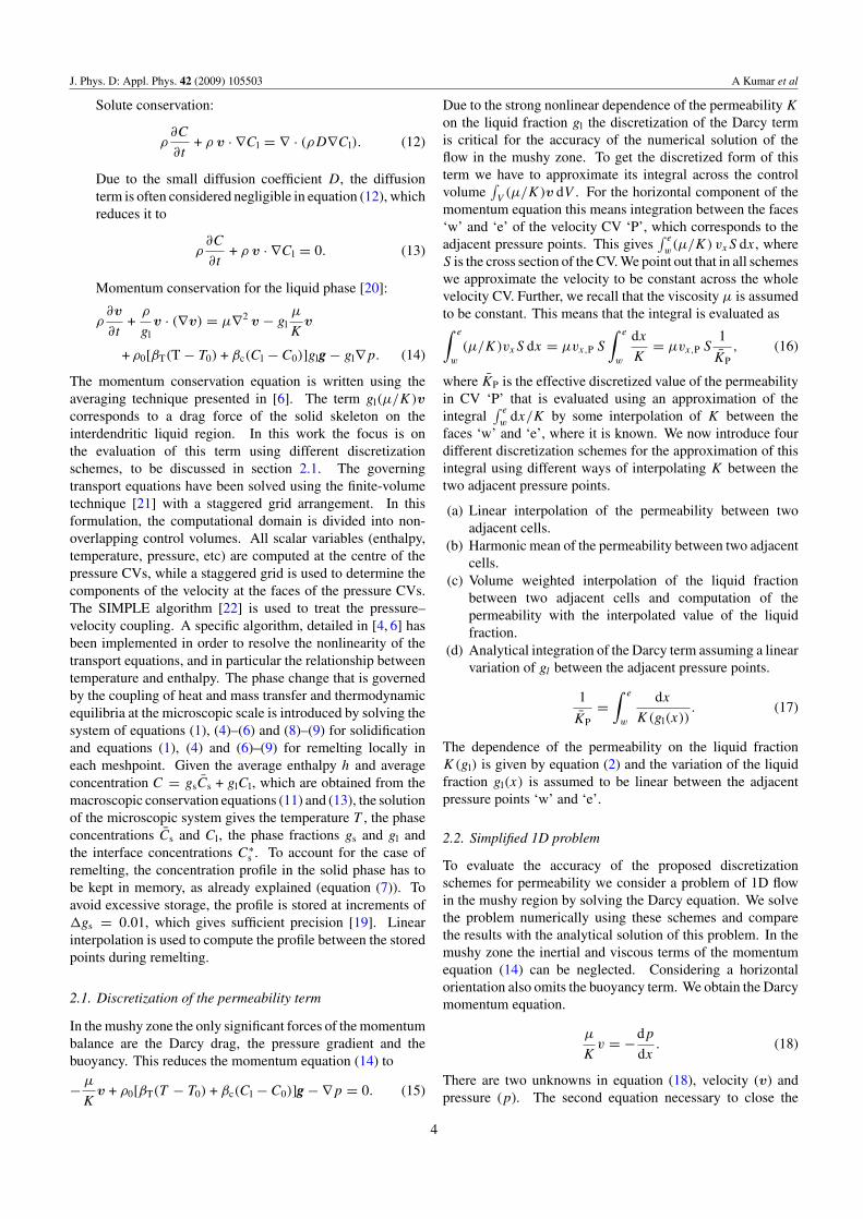
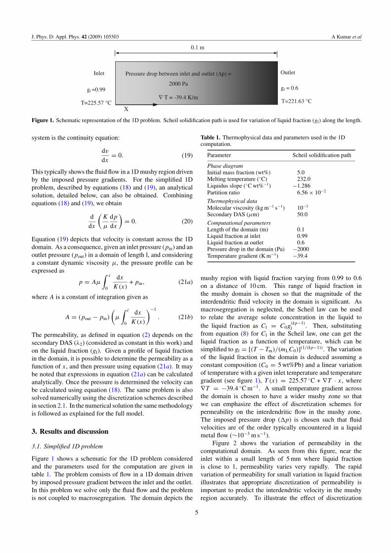
Figure 2 shows the variation of permeability in thecomputational domain. As seen from this figure, near theinlet within a small length of 5 mm where liquid fractionis close to 1, permeability varies very rapidly. The rapidvariation of permeability for small variation in liquid fractionillustrates that appropriate discretization of permeability isimportant to predict the interdendritic velocity in the mushyregion accurately. To illustrate the effect of discretization
5
J. Phys. D: Appl. Phys. 42 (2009) 105503 A Kumar et al
1.0E-11
1.0E-10
1.0E-09
1.0E-08
1.0E-07
1.0E-06
0 0.02 0.04 0.06 0.08 0.1
K (
m2 )
0.4
0.5
0.6
0.7
0.8
0.9
1
liqui
d fr
actio
n
Permeability
Liquid fraction
x (m)
*
Figure 2. Variation of permeability and liquid fraction along thecomputational domain. Scheil solidification path is used for thevariation of liquid fraction along the computational domain.Permeability values for various discretization schemes consideringtwo mesh cells in the domain are shown at the mid-length of thedomain: •, harmonic mean; �, analytical integration; ∗,interpolated liquid fraction; ◦, linear mean.
–5
0
5
10
15
20
0 10 20 30 40 50 60 70 80 90 100
harmonic mean
interpolated liquid fraction
linear mean
analytical integration
Dev
iatio
n of
vel
ocity
from
the
exac
t sol
utio
n (%
)
Number of nodes
Figure 3. Variation of deviation of velocity obtained using variousdiscretization schemes from the exact solution with number ofnodes (1D case). The magnitude of the velocity is obtained usingexact solution is 1.2414 mm s−1.
schemes on permeability, we have also shown in figure 2 thevalues of permeability obtained using various discretizationschemes at the mid-width of the domain. Harmonic meaninterpolation underestimates the permeability; however, otherschemes overestimate it.
In figure 3 we compare the computed velocity for the1D problem using various interpolation schemes, discussedin section 2.1 and the grid convergence of the solution. Thefigure shows the deviation from the exact solution for velocitywhere the exact solution corresponds to the evaluation ofthe pressure field in equation (21a) by numerical integrationusing the trapezoidal method and then the calculation ofvelocity using equation (18). As seen from figure 3, thelinear interpolation leads to the largest deviation from the exactsolution. Harmonic mean and calculation of permeabilitywith interpolated liquid fraction show less deviation from theexact values. The harmonic mean solution underestimates thepredictions whereas solution using interpolated liquid fractionoverestimates it. This is intuitive if one observes values of
g
X
Y
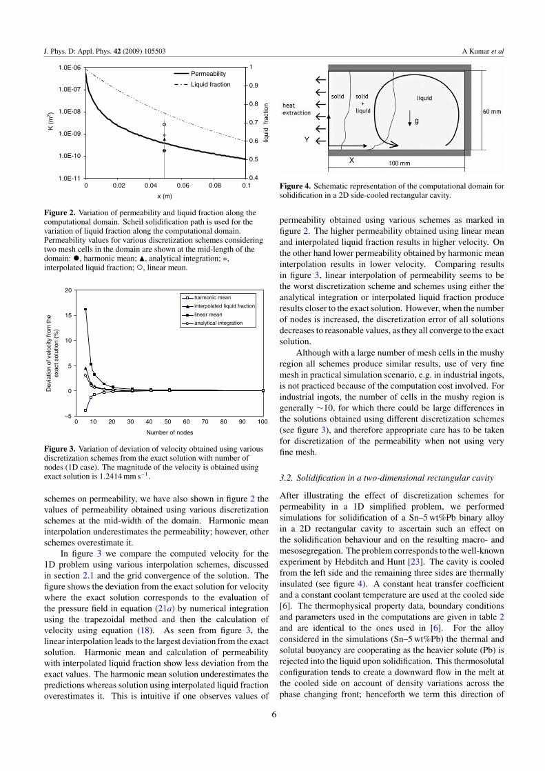
Figure 4. Schematic representation of the computational domain forsolidification in a 2D side-cooled rectangular cavity.
permeability obtained using various schemes as marked infigure 2. The higher permeability obtained using linear meanand interpolated liquid fraction results in higher velocity. Onthe other hand lower permeability obtained by harmonic meaninterpolation results in lower velocity. Comparing resultsin figure 3, linear interpolation of permeability seems to bethe worst discretization scheme and schemes using either theanalytical integration or interpolated liquid fraction produceresults closer to the exact solution. However, when the numberof nodes is increased, the discretization error of all solutionsdecreases to reasonable values, as they all converge to the exactsolution.
Although with a large number of mesh cells in the mushyregion all schemes produce similar results, use of very finemesh in practical simulation scenario, e.g. in industrial ingots,is not practiced because of the computation cost involved. Forindustrial ingots, the number of cells in the mushy region isgenerally ∼10, for which there could be large differences inthe solutions obtained using different discretization schemes(see figure 3), and therefore appropriate care has to be takenfor discretization of the permeability when not using veryfine mesh.
3.2. Solidification in a two-dimensional rectangular cavity
After illustrating the effect of discretization schemes forpermeability in a 1D simplified problem, we performedsimulations for solidification of a Sn–5 wt%Pb binary alloyin a 2D rectangular cavity to ascertain such an effect onthe solidification behaviour and on the resulting macro- andmesosegregation. The problem corresponds to the well-knownexperiment by Hebditch and Hunt [23]. The cavity is cooledfrom the left side and the remaining three sides are thermallyinsulated (see figure 4). A constant heat transfer coefficientand a constant coolant temperature are used at the cooled side[6]. The thermophysical property data, boundary conditionsand parameters used in the computations are given in table 2and are identical to the ones used in [6]. For the alloyconsidered in the simulations (Sn–5 wt%Pb) the thermal andsolutal buoyancy are cooperating as the heavier solute (Pb) isrejected into the liquid upon solidification. This thermosolutalconfiguration tends to create a downward flow in the melt atthe cooled side on account of density variations across thephase changing front; henceforth we term this direction of
6
J. Phys. D: Appl. Phys. 42 (2009) 105503 A Kumar et al
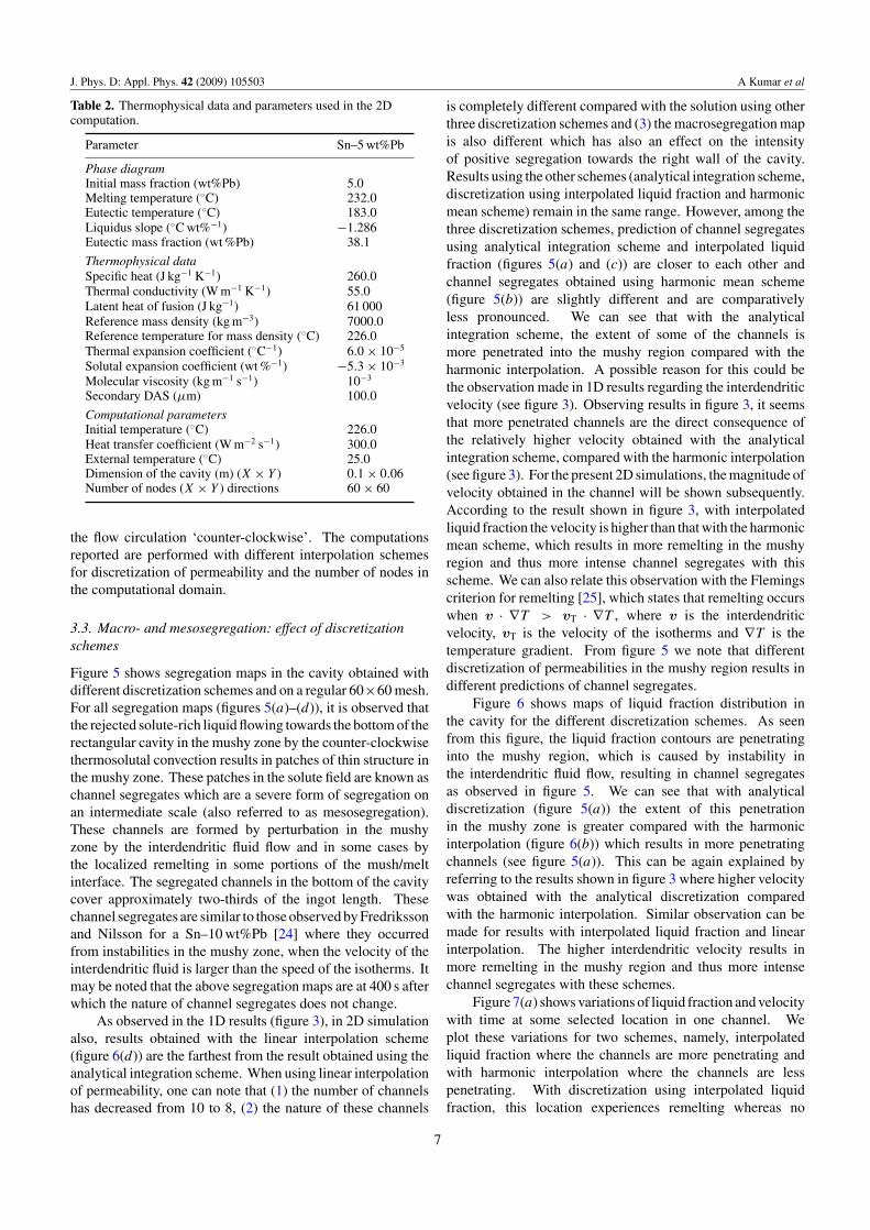
Table 2. Thermophysical data and parameters used in the 2Dcomputation.
Parameter Sn–5 wt%Pb
Phase diagramInitial mass fraction (wt%Pb) 5.0Melting temperature (◦C) 232.0Eutectic temperature (◦C) 183.0Liquidus slope (◦C wt%−1) −1.286Eutectic mass fraction (wt %Pb) 38.1
Thermophysical dataSpecific heat (J kg−1 K−1) 260.0Thermal conductivity (W m−1 K−1) 55.0Latent heat of fusion (J kg−1) 61 000Reference mass density (kg m−3) 7000.0Reference temperature for mass density (◦C) 226.0Thermal expansion coefficient (◦C−1) 6.0 × 10⁻⁵
Solutal expansion coefficient (wt %−1) −5.3 × 10⁻³
Molecular viscosity (kg m−1 s−1) 10−3
Secondary DAS (µm) 100.0
Computational parametersInitial temperature (◦C) 226.0Heat transfer coefficient (W m−2 s−1) 300.0External temperature (◦C) 25.0Dimension of the cavity (m) (X × Y ) 0.1 × 0.06Number of nodes (X × Y ) directions 60 × 60
the flow circulation ‘counter-clockwise’. The computationsreported are performed with different interpolation schemesfor discretization of permeability and the number of nodes inthe computational domain.
3.3. Macro- and mesosegregation: effect of discretizationschemes
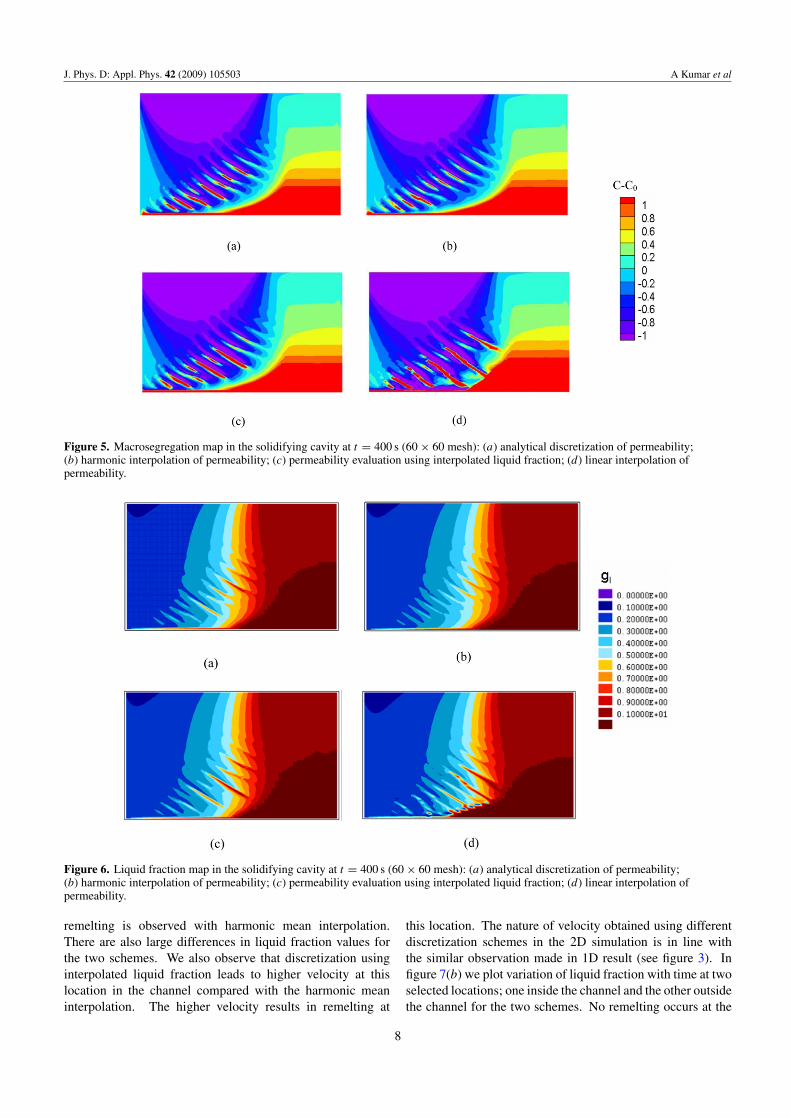
Figure 5 shows segregation maps in the cavity obtained withdifferent discretization schemes and on a regular 60×60 mesh.For all segregation maps (figures 5(a)–(d)), it is observed thatthe rejected solute-rich liquid flowing towards the bottom of therectangular cavity in the mushy zone by the counter-clockwisethermosolutal convection results in patches of thin structure inthe mushy zone. These patches in the solute field are known aschannel segregates which are a severe form of segregation onan intermediate scale (also referred to as mesosegregation).These channels are formed by perturbation in the mushyzone by the interdendritic fluid flow and in some cases bythe localized remelting in some portions of the mush/meltinterface. The segregated channels in the bottom of the cavitycover approximately two-thirds of the ingot length. Thesechannel segregates are similar to those observed by Fredrikssonand Nilsson for a Sn–10 wt%Pb [24] where they occurredfrom instabilities in the mushy zone, when the velocity of theinterdendritic fluid is larger than the speed of the isotherms. Itmay be noted that the above segregation maps are at 400 s afterwhich the nature of channel segregates does not change.
As observed in the 1D results (figure 3), in 2D simulationalso, results obtained with the linear interpolation scheme(figure 6(d)) are the farthest from the result obtained using theanalytical integration scheme. When using linear interpolationof permeability, one can note that (1) the number of channelshas decreased from 10 to 8, (2) the nature of these channels
is completely different compared with the solution using otherthree discretization schemes and (3) the macrosegregation mapis also different which has also an effect on the intensityof positive segregation towards the right wall of the cavity.Results using the other schemes (analytical integration scheme,discretization using interpolated liquid fraction and harmonicmean scheme) remain in the same range. However, among thethree discretization schemes, prediction of channel segregatesusing analytical integration scheme and interpolated liquidfraction (figures 5(a) and (c)) are closer to each other andchannel segregates obtained using harmonic mean scheme(figure 5(b)) are slightly different and are comparativelyless pronounced. We can see that with the analyticalintegration scheme, the extent of some of the channels ismore penetrated into the mushy region compared with theharmonic interpolation. A possible reason for this could bethe observation made in 1D results regarding the interdendriticvelocity (see figure 3). Observing results in figure 3, it seemsthat more penetrated channels are the direct consequence ofthe relatively higher velocity obtained with the analyticalintegration scheme, compared with the harmonic interpolation(see figure 3). For the present 2D simulations, the magnitude ofvelocity obtained in the channel will be shown subsequently.According to the result shown in figure 3, with interpolatedliquid fraction the velocity is higher than that with the harmonicmean scheme, which results in more remelting in the mushyregion and thus more intense channel segregates with thisscheme. We can also relate this observation with the Flemingscriterion for remelting [25], which states that remelting occurswhen v · ∇T > vT · ∇T , where v is the interdendriticvelocity, vT is the velocity of the isotherms and ∇T is thetemperature gradient. From figure 5 we note that differentdiscretization of permeabilities in the mushy region results indifferent predictions of channel segregates.
Figure 6 shows maps of liquid fraction distribution inthe cavity for the different discretization schemes. As seenfrom this figure, the liquid fraction contours are penetratinginto the mushy region, which is caused by instability inthe interdendritic fluid flow, resulting in channel segregatesas observed in figure 5. We can see that with analyticaldiscretization (figure 5(a)) the extent of this penetrationin the mushy zone is greater compared with the harmonicinterpolation (figure 6(b)) which results in more penetratingchannels (see figure 5(a)). This can be again explained byreferring to the results shown in figure 3 where higher velocitywas obtained with the analytical discretization comparedwith the harmonic interpolation. Similar observation can bemade for results with interpolated liquid fraction and linearinterpolation. The higher interdendritic velocity results inmore remelting in the mushy region and thus more intensechannel segregates with these schemes.
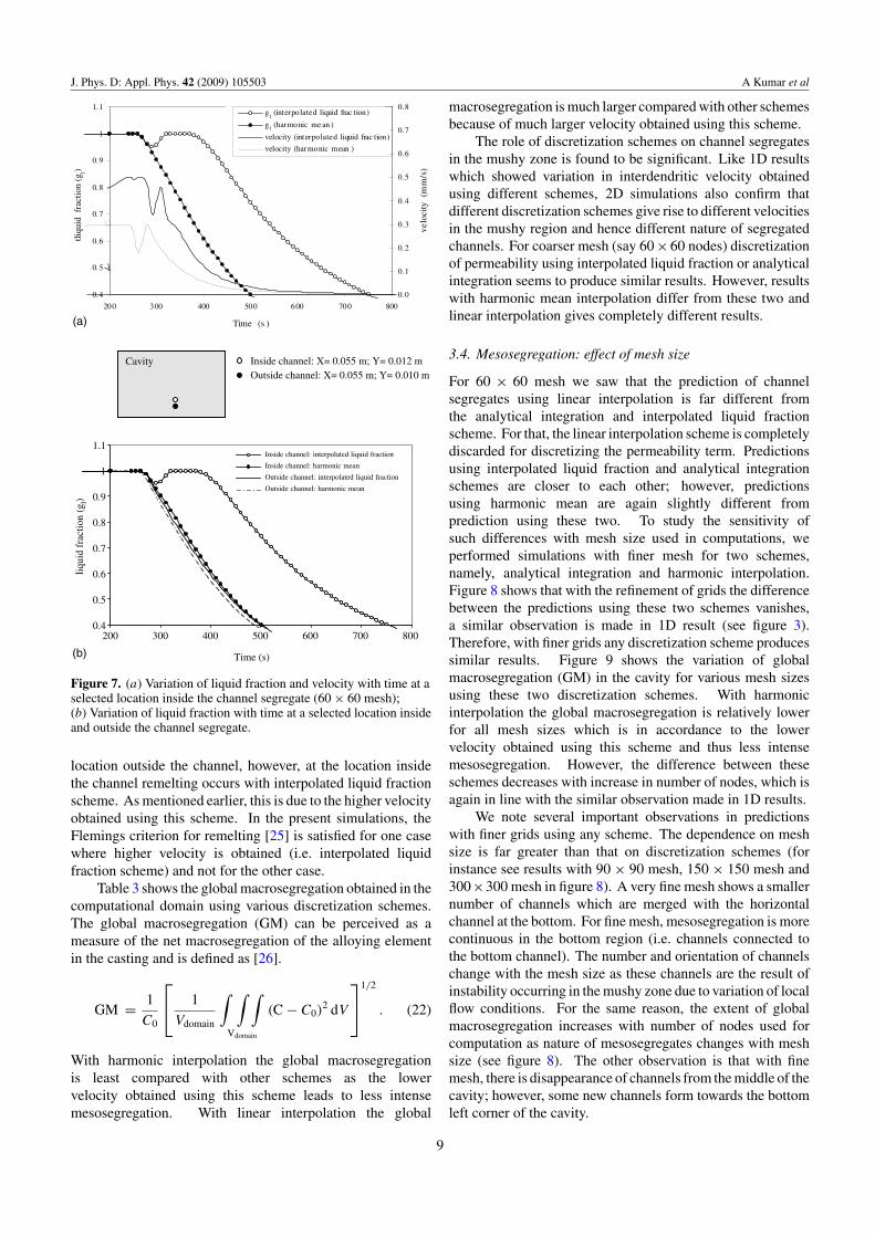
Figure 7(a) shows variations of liquid fraction and velocitywith time at some selected location in one channel. Weplot these variations for two schemes, namely, interpolatedliquid fraction where the channels are more penetrating andwith harmonic interpolation where the channels are lesspenetrating. With discretization using interpolated liquidfraction, this location experiences remelting whereas no
7
J. Phys. D: Appl. Phys. 42 (2009) 105503 A Kumar et al
Figure 5. Macrosegregation map in the solidifying cavity at t = 400 s (60 × 60 mesh): (a) analytical discretization of permeability;(b) harmonic interpolation of permeability; (c) permeability evaluation using interpolated liquid fraction; (d) linear interpolation ofpermeability.
Figure 6. Liquid fraction map in the solidifying cavity at t = 400 s (60 × 60 mesh): (a) analytical discretization of permeability;(b) harmonic interpolation of permeability; (c) permeability evaluation using interpolated liquid fraction; (d) linear interpolation ofpermeability.
remelting is observed with harmonic mean interpolation.There are also large differences in liquid fraction values forthe two schemes. We also observe that discretization usinginterpolated liquid fraction leads to higher velocity at thislocation in the channel compared with the harmonic meaninterpolation. The higher velocity results in remelting at
this location. The nature of velocity obtained using differentdiscretization schemes in the 2D simulation is in line withthe similar observation made in 1D result (see figure 3). Infigure 7(b) we plot variation of liquid fraction with time at twoselected locations; one inside the channel and the other outsidethe channel for the two schemes. No remelting occurs at the
8
J. Phys. D: Appl. Phys. 42 (2009) 105503 A Kumar et al
0.4
0.5
0.6
0.7
0.8
0.9
1
1.1
200 300 400 500 600 700
liqui
d fr
actio
n (g
l)
Inside channel: interpolated liquid fraction
Cavity
Inside channel: X= 0.055 m; Y= 0.012 m Outside channel: X= 0.055 m; Y= 0.010 m
Inside channel: harmonic mean
Outside channel: interpolated liquid fraction
Outside channel: harmonic mean
Time (s)
800
0.4
0.5
0.6
0.7
0.8
0.9
1
1.1
200 300 400 500 600 700 800
Time (s )
tliqu
id f
ract
ion
(gl)
0.0
0.1
0.2
0.3
0.4
0.5
0.6
0.7
0.8
velo
city
(m
m/s
)
g (interpolated liquid frac tion)
g (harmonic me an )
velocity (interpolated liquid frac tion)
velocity (har monic mean )
l
l
(b)
(a)
Figure 7. (a) Variation of liquid fraction and velocity with time at aselected location inside the channel segregate (60 × 60 mesh);(b) Variation of liquid fraction with time at a selected location insideand outside the channel segregate.
location outside the channel, however, at the location insidethe channel remelting occurs with interpolated liquid fractionscheme. As mentioned earlier, this is due to the higher velocityobtained using this scheme. In the present simulations, theFlemings criterion for remelting [25] is satisfied for one casewhere higher velocity is obtained (i.e. interpolated liquidfraction scheme) and not for the other case.
Table 3 shows the global macrosegregation obtained in thecomputational domain using various discretization schemes.The global macrosegregation (GM) can be perceived as ameasure of the net macrosegregation of the alloying elementin the casting and is defined as [26].
GM = 1
C0
1
Vdomain
∫ ∫ ∫Vdomain
(C − C0)2 dV
1/2
. (22)
With harmonic interpolation the global macrosegregationis least compared with other schemes as the lowervelocity obtained using this scheme leads to less intensemesosegregation. With linear interpolation the global
macrosegregation is much larger compared with other schemesbecause of much larger velocity obtained using this scheme.
The role of discretization schemes on channel segregatesin the mushy zone is found to be significant. Like 1D resultswhich showed variation in interdendritic velocity obtainedusing different schemes, 2D simulations also confirm thatdifferent discretization schemes give rise to different velocitiesin the mushy region and hence different nature of segregatedchannels. For coarser mesh (say 60 × 60 nodes) discretizationof permeability using interpolated liquid fraction or analyticalintegration seems to produce similar results. However, resultswith harmonic mean interpolation differ from these two andlinear interpolation gives completely different results.
3.4. Mesosegregation: effect of mesh size
For 60 × 60 mesh we saw that the prediction of channelsegregates using linear interpolation is far different fromthe analytical integration and interpolated liquid fractionscheme. For that, the linear interpolation scheme is completelydiscarded for discretizing the permeability term. Predictionsusing interpolated liquid fraction and analytical integrationschemes are closer to each other; however, predictionsusing harmonic mean are again slightly different fromprediction using these two. To study the sensitivity ofsuch differences with mesh size used in computations, weperformed simulations with finer mesh for two schemes,namely, analytical integration and harmonic interpolation.Figure 8 shows that with the refinement of grids the differencebetween the predictions using these two schemes vanishes,a similar observation is made in 1D result (see figure 3).Therefore, with finer grids any discretization scheme producessimilar results. Figure 9 shows the variation of globalmacrosegregation (GM) in the cavity for various mesh sizesusing these two discretization schemes. With harmonicinterpolation the global macrosegregation is relatively lowerfor all mesh sizes which is in accordance to the lowervelocity obtained using this scheme and thus less intensemesosegregation. However, the difference between theseschemes decreases with increase in number of nodes, which isagain in line with the similar observation made in 1D results.
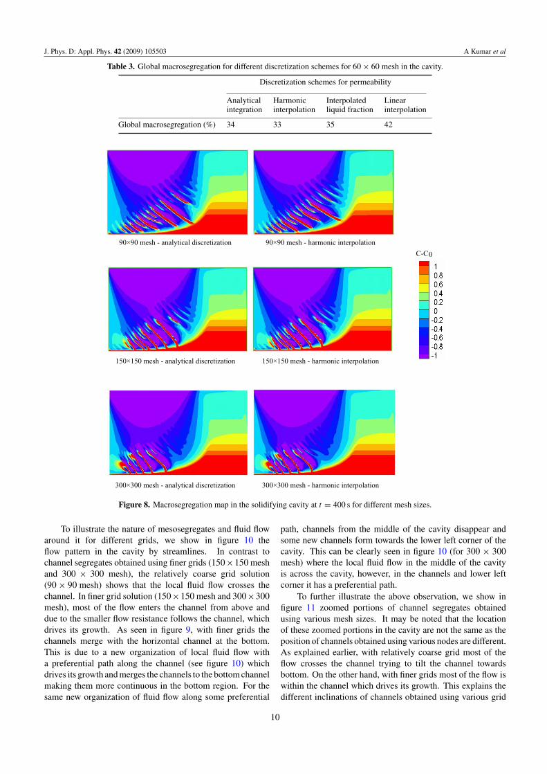
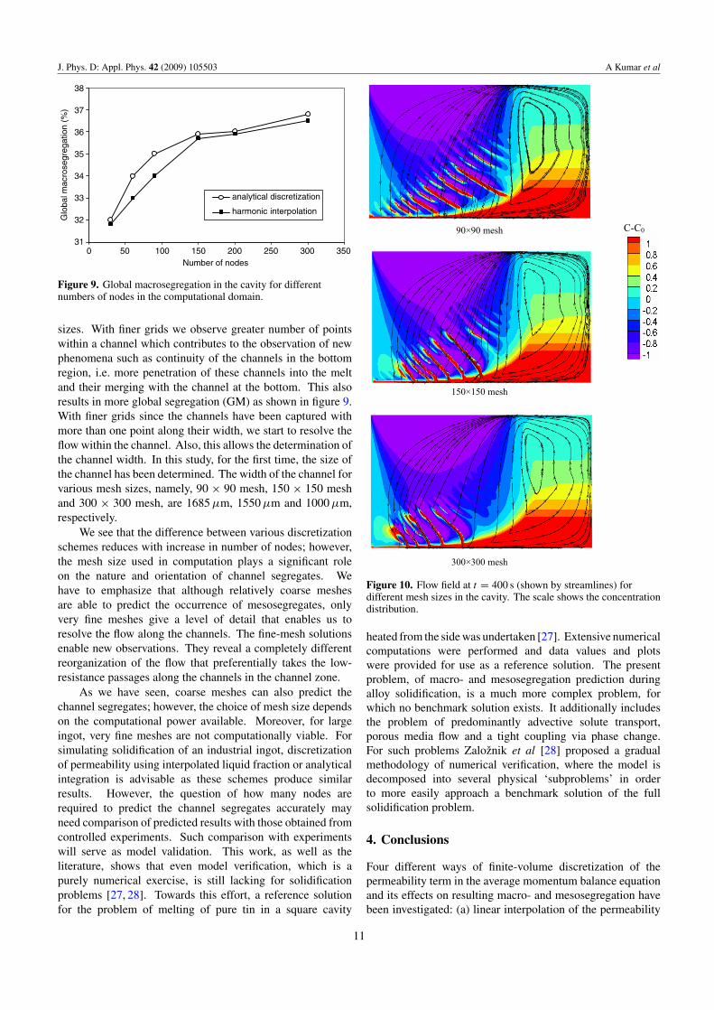
We note several important observations in predictionswith finer grids using any scheme. The dependence on meshsize is far greater than that on discretization schemes (forinstance see results with 90 × 90 mesh, 150 × 150 mesh and300×300 mesh in figure 8). A very fine mesh shows a smallernumber of channels which are merged with the horizontalchannel at the bottom. For fine mesh, mesosegregation is morecontinuous in the bottom region (i.e. channels connected tothe bottom channel). The number and orientation of channelschange with the mesh size as these channels are the result ofinstability occurring in the mushy zone due to variation of localflow conditions. For the same reason, the extent of globalmacrosegregation increases with number of nodes used forcomputation as nature of mesosegregates changes with meshsize (see figure 8). The other observation is that with finemesh, there is disappearance of channels from the middle of thecavity; however, some new channels form towards the bottomleft corner of the cavity.
9
J. Phys. D: Appl. Phys. 42 (2009) 105503 A Kumar et al
Table 3. Global macrosegregation for different discretization schemes for 60 × 60 mesh in the cavity.
Discretization schemes for permeability
Analytical Harmonic Interpolated Linearintegration interpolation liquid fraction interpolation
Global macrosegregation (%) 34 33 35 42
90×90 mesh - analytical discretization
C-C0
90×90 mesh - harmonic interpolation
150×150 mesh - analytical discretization 150×150 mesh - harmonic interpolation
300×300 mesh - harmonic interpolation 300×300 mesh - analytical discretization
Figure 8. Macrosegregation map in the solidifying cavity at t = 400 s for different mesh sizes.
To illustrate the nature of mesosegregates and fluid flowaround it for different grids, we show in figure 10 theflow pattern in the cavity by streamlines. In contrast tochannel segregates obtained using finer grids (150×150 meshand 300 × 300 mesh), the relatively coarse grid solution(90 × 90 mesh) shows that the local fluid flow crosses thechannel. In finer grid solution (150×150 mesh and 300×300mesh), most of the flow enters the channel from above anddue to the smaller flow resistance follows the channel, whichdrives its growth. As seen in figure 9, with finer grids thechannels merge with the horizontal channel at the bottom.This is due to a new organization of local fluid flow witha preferential path along the channel (see figure 10) whichdrives its growth and merges the channels to the bottom channelmaking them more continuous in the bottom region. For thesame new organization of fluid flow along some preferential
path, channels from the middle of the cavity disappear andsome new channels form towards the lower left corner of thecavity. This can be clearly seen in figure 10 (for 300 × 300mesh) where the local fluid flow in the middle of the cavityis across the cavity, however, in the channels and lower leftcorner it has a preferential path.
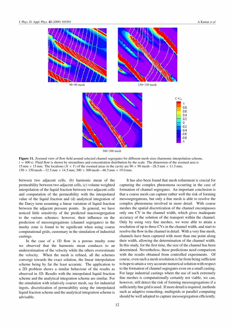
To further illustrate the above observation, we show infigure 11 zoomed portions of channel segregates obtainedusing various mesh sizes. It may be noted that the locationof these zoomed portions in the cavity are not the same as theposition of channels obtained using various nodes are different.As explained earlier, with relatively coarse grid most of theflow crosses the channel trying to tilt the channel towardsbottom. On the other hand, with finer grids most of the flow iswithin the channel which drives its growth. This explains thedifferent inclinations of channels obtained using various grid
10
J. Phys. D: Appl. Phys. 42 (2009) 105503 A Kumar et al
31
32
33
34
35
36
37
38
0 50 100 150 200 250 300 350
Glo
bal m
acro
segr
egat
ion
(%)
analytical discretization
harmonic interpolation
Number of nodes
Figure 9. Global macrosegregation in the cavity for differentnumbers of nodes in the computational domain.
sizes. With finer grids we observe greater number of pointswithin a channel which contributes to the observation of newphenomena such as continuity of the channels in the bottomregion, i.e. more penetration of these channels into the meltand their merging with the channel at the bottom. This alsoresults in more global segregation (GM) as shown in figure 9.With finer grids since the channels have been captured withmore than one point along their width, we start to resolve theflow within the channel. Also, this allows the determination ofthe channel width. In this study, for the first time, the size ofthe channel has been determined. The width of the channel forvarious mesh sizes, namely, 90 × 90 mesh, 150 × 150 meshand 300 × 300 mesh, are 1685 µm, 1550 µm and 1000 µm,respectively.
We see that the difference between various discretizationschemes reduces with increase in number of nodes; however,the mesh size used in computation plays a significant roleon the nature and orientation of channel segregates. Wehave to emphasize that although relatively coarse meshesare able to predict the occurrence of mesosegregates, onlyvery fine meshes give a level of detail that enables us toresolve the flow along the channels. The fine-mesh solutionsenable new observations. They reveal a completely differentreorganization of the flow that preferentially takes the low-resistance passages along the channels in the channel zone.
As we have seen, coarse meshes can also predict thechannel segregates; however, the choice of mesh size dependson the computational power available. Moreover, for largeingot, very fine meshes are not computationally viable. Forsimulating solidification of an industrial ingot, discretizationof permeability using interpolated liquid fraction or analyticalintegration is advisable as these schemes produce similarresults. However, the question of how many nodes arerequired to predict the channel segregates accurately mayneed comparison of predicted results with those obtained fromcontrolled experiments. Such comparison with experimentswill serve as model validation. This work, as well as theliterature, shows that even model verification, which is apurely numerical exercise, is still lacking for solidificationproblems [27, 28]. Towards this effort, a reference solutionfor the problem of melting of pure tin in a square cavity
C-C0
150×150 mesh
90×90 mesh
300×300 mesh
Figure 10. Flow field at t = 400 s (shown by streamlines) fordifferent mesh sizes in the cavity. The scale shows the concentrationdistribution.
heated from the side was undertaken [27]. Extensive numericalcomputations were performed and data values and plotswere provided for use as a reference solution. The presentproblem, of macro- and mesosegregation prediction duringalloy solidification, is a much more complex problem, forwhich no benchmark solution exists. It additionally includesthe problem of predominantly advective solute transport,porous media flow and a tight coupling via phase change.For such problems Zaloznik et al [28] proposed a gradualmethodology of numerical verification, where the model isdecomposed into several physical ‘subproblems’ in orderto more easily approach a benchmark solution of the fullsolidification problem.
4. Conclusions
Four different ways of finite-volume discretization of thepermeability term in the average momentum balance equationand its effects on resulting macro- and mesosegregation havebeen investigated: (a) linear interpolation of the permeability
11
J. Phys. D: Appl. Phys. 42 (2009) 105503 A Kumar et al
C-C0
90×90 mesh 150×150 mesh
300×300 mesh
Figure 11. Zoomed view of flow field around selected channel segregates for different mesh sizes (harmonic interpolation scheme,t = 400 s). Fluid flow is shown by streamlines and concentration distribution by the scale. The dimension of the zoomed area is15 mm × 15 mm. The locations (X × Y ) of the zoomed areas in the cavity are 90 × 90 mesh—28.5 mm × 11.5 mm;150 × 150 mesh—32.5 mm × 14.5 mm; 300 × 300 mesh—46.5 mm × 19.0 mm.
between two adjacent cells, (b) harmonic mean of thepermeability between two adjacent cells, (c) volume weightedinterpolation of the liquid fraction between two adjacent cellsand computation of the permeability with the interpolatedvalue of the liquid fraction and (d) analytical integration ofthe Darcy term assuming a linear variation of liquid fractionbetween the adjacent pressure points. In general, we havenoticed little sensitivity of the predicted macrosegregationto the various schemes; however, their influence on theprediction of mesosegregations (channel segregates) in themushy zone is found to be significant when using coarsecomputational grids, customary in the simulation of industrialcastings.
In the case of a 1D flow in a porous mushy zonewe observed that the harmonic mean conduces to anunderestimation of the velocity while the others overestimatethe velocity. When the mesh is refined, all the schemesconverge towards the exact solution, the linear interpolationscheme being by far the least accurate. The application toa 2D problem shows a similar behaviour of the results asobserved in 1D. Results with the interpolated liquid fractionscheme and the analytical integration scheme are similar. Forthe simulation with relatively coarser mesh, say for industrialingots, discretization of permeability using the interpolatedliquid fraction scheme and the analytical integration scheme isadvisable.
It has also been found that mesh refinement is crucial forcapturing the complex phenomena occurring in the case offormation of channel segregates. An important conclusion isthat a coarse mesh can capture rather well the risk of formingmesosegregations, but only a fine mesh is able to resolve thecomplex phenomena involved in more detail. With coarsemeshes the spatial discretization of the channel encompassesonly one CV in the channel width, which gives inadequateaccuracy of the solution of the transport within the channel.Only by using very fine meshes, we were able to attain aresolution of up to three CVs in the channel width, and start toresolve the flow in the channel in detail. With a very fine mesh,channels have been captured with more than one point alongtheir width, allowing the determination of the channel width.In this study, for the first time, the size of the channel has beendetermined. Nevertheless, these predictions need comparisonwith the results obtained from controlled experiments. Ofcourse, even such a mesh resolution is far from being sufficientto hope to attain a very accurate numerical solution with respectto the formation of channel segregates even on a small casting.For large industrial castings where the use of such extremelyfine meshes is computationally certainly not viable, we can,however, still detect the risk of forming mesosegregations if asufficiently fine grid is used. If more detail is required, methodssuch as adaptive remeshing, multigrids or parallel computingshould be well adopted to capture mesosegregation efficiently.
12
J. Phys. D: Appl. Phys. 42 (2009) 105503 A Kumar et al
Acknowledgments
This work has been performed in the framework of the project‘SMACS’ No BLAN07-2 193017 financed by ANR.
References
[1] Prakash C and Voller V R 1989 On the Numerical solution ofcontinuum mixture equations describing binary solid–liquidphase change Numer. Heat Transfer B 15 171–89
[2] Bennon W D and Incropera F P 1987 A continuum model formomentum, heat and species transport in binarysolid–liquid phase change systems: I. Model formulationInt. J. Heat Mass Transfer 30 2161–70
[3] Bennon W D and Incropera F P 1988 Numerical analysis ofbinary solid–liquid phase change using a continuum modelNumer. Heat Transfer 13 277–96
[4] Vannier I, Combeau H and Lesoult G 1993 Numerical modelfor prediction of the final segregation pattern of bearingsteel ingots Mater. Sci. Eng. A 173 317–21
[5] Chakraborty S and Dutta P 2003 Three dimensionaldouble-diffusive convection and macrosegregation duringnon-equilibrium solidification of binary mixtures Int. J.Heat Mass Transfer 46 2115–34
[6] Ahmad N, Combeau H, Desbiolles J-L, Jalanti T, Lesoult G,Rappaz J, Rappaz M and Stomp C 1998 Numericalsimulation of macrosegregation: a comparison betweenfinite volume method and finite element method predictionsand a confrontation with experiments Metall. Mater. Trans.A 29 617–30
[7] Jain J, Kumar A and Dutta P 2007 Numerical studies onchannel formation and growth during solidification: effectof process parameters J. Heat Transfer-Trans. ASME129 548–58
[8] Jain J, Kumar A and Dutta P 2007 Role of plume convectionand remelting on the mushy layer structure duringdirectional solidification J. Phys. D: Appl. Phys.40 1150–60
[9] Combeau H, Zaloznik M, Hans S and Richy P E 2009Prediction of macrosegregation in steel ingots: influence ofthe motion and the morphology of equiaxed grains Metall.Mater. Trans. B at press doi:10.1007/s11663-008-9178-y
[10] Ni J and Beckermann C 1991 A volume-averaged two-phasemodel for transport phenomena during solidification Metall.Mater. Trans. B 22 349–61
[11] Rappaz M and Voller V R 1990 Modeling ofmicro-macrosegregation in solidification processes Metall.Trans. A 21 749–53
[12] Nandapurkar P, Poirier D R, Heinrich J C and Felicelli S 1989Thermosolutal convection during dendritic solidification of
alloys: I. Linear stability analysis Metall. Trans. B20 711–21
[13] Mo A, Rusten T, Thevik H J, Henriksen B R and Jensen E K1997 Modelling of surface segregation development duringDC casting of rolling slab ingots Proc. 126th Annual TMSMeeting (Light Metals) (Orlando, FL) (Warrendale, PA:TMS) pp 667–74
[14] Poirier D R, Nandapurkar P and Ganesan S 1991 Energy andsolute conservation equations for dendritic solidificationMetall. Trans. B 22 889–900
[15] Gouttebroze S, Bellet M and Combeau H 2007 3Dmacrosegregation simulation with anisotropic remeshingC. R. Mec. 335 269–79
[16] Katz R F and Worster M G 2008 Simulation of directionalsolidification, thermochemical convection, and chimneyformation in a Hele–Shaw cell J. Comput. Phys.227 9823–40
[17] Scheidegger A E 1974 The Physics of Flow Through PorousMedia 3rd edn (Toronto, Canada: University of TorontoPress)
[18] Heinrich J C and Poirier D R 2004 Convection modeling indirectional solidification C. R. Mec. 332 429–45
[19] Kumar A, Walker M J, Sundarraj S and Dutta P 2007Remelting of solid and its effect on macrosegregationduring solidification Numer. Heat Transfer A 51 59–83
[20] Ganesan S and Poirier D R 1990 Conservation of mass andmomentum for the flow of interdendritic liquid duringsolidification Metall. Trans. B 21 173–81
[21] Patankar S V 1980 Numerical Heat Transfer and Fluid Flow(Washington, DC: Hemisphere)
[22] van Doormaal J P and Raithby G D 1984 Enhancements of theSIMPLE method for predicting incompressible fluid flowsNumer. Heat Transfer 7 147–63
[23] Hebditch D and Hunt J 1974 Observation of ingotmacrosegregation on model systems Metall. Trans.5 1557–64
[24] Fredriksson H and Nilsson S O 1978 On the formation ofmacrosegregations in ingots Metall. Trans. B 9 111–20
[25] Mehrabian R, Keane M and Flemings M C 1970 Interdendriticfluid flow and macrosegregation: influence of gravityMetall. Trans. 1 1209–20
[26] Schneider M and Beckermann C 1995 Formation ofmacrosegregation by multicomponent thermosolutalconvection during the solidification of steel Metall. Metall.Trans. A 26 2373–88
[27] Hannoun N, Alexiades V and Mai T Z 2005 A referencesolution for phase change with convection Int. J. Numer.Methods Fluids 48 1283–308
[28] Zaloznik M, Xin S and Sarler B 2008 Verification of anumerical model of macrosegregation in direct chill castingInt. J. Numer. Methods Heat and Fluid Flow 18 308–24
13
Related Documents