doi:10.1016/j.promfg.2016.08.029 Effect of Cutting Fluid on Micromilling of Ti-6Al-4V Titanium Alloy Maksym Ziberov 1 , Márcio Bacci da Silva 1 , Mark Jackson 2 and Wayne N.P. Hung 3 1 Federal University of Uberlandia, Uberlandia, Brazil. 2 Kansas State University, Salinas, Kansas, USA 3 Texas A&M University, College Station, Texas, USA. [email protected], [email protected], [email protected], [email protected] Abstract This paper studies the micromilling of Ti-6Al-4V titanium alloy. The main objective of this work is to study the performance of micromill tools in terms of burrs, machined surface and tool wear in machining of Ti-6Al-4V titanium alloy and evaluate the effect of the application of cutting fluid. Experimental micromilling tests with 152.4 Pm diameter WC tools were made. The tests were carried out on a four axis CNC milling machine with maximum spindle speed of 60,000 rpm and a resolution of 0.1 Pm. To measure the burr height, a profilometer with 1.0 mm measuring range and 16 nm resolution was used. The samples and tools were observed under scanning electron microscope to evaluate the machined surface quality, to measure wear and to analyse wear mechanisms. The results show that the application of cutting fluid has a large effect on the quality of the machined parts, both in terms of burrs formed and in terms of machined surface quality. Depending on the cutting conditions, the relative size of the burrs formed is much higher than in macromachining operations. Built up edges on cutting tool affects tool life and surface finish. Keywords: Micromachining, Micromilling, Ti-6Al-4V, Built Up Edge. 1 Introduction Mechanical micromachining is the manufacturing method for miniaturized devices and components of sizes ranging from tens of microns to several millimeters. Figure 1 shows a comparison between the dimensions involved in manufacturing processes. Various micro products have been used in the mechanical industry for a long time, for example, clock gears, micro transmissors and micro molds (Meijer et al., 2002, Fleischer et. al, 2003). With the development of technology related to these processes, some traditional products have been benefitted with an increase of the area/weight ratio (Camara et al., 2012). For example, Byrne et al. (2003) reported Procedia Manufacturing Volume 5, 2016, Pages 332–347 44th Proceedings of the North American Manufacturing Research Institution of SME http://www.sme.org/namrc 332 Selection and peer-review under responsibility of the Scientific Programme Committee of NAMRI/SME c The Authors. Published by Elsevier B.V.

Welcome message from author
This document is posted to help you gain knowledge. Please leave a comment to let me know what you think about it! Share it to your friends and learn new things together.
Transcript

doi: 10.1016/j.promfg.2016.08.029
Effect of Cutting Fluid on Micromilling of Ti-6Al-4V Titanium Alloy
Maksym Ziberov1, Márcio Bacci da Silva1, Mark Jackson2 and Wayne N.P. Hung3
1Federal University of Uberlandia, Uberlandia, Brazil. 2Kansas State University, Salinas, Kansas, USA
3Texas A&M University, College Station, Texas, USA. [email protected], [email protected], [email protected], [email protected]
Abstract This paper studies the micromilling of Ti-6Al-4V titanium alloy. The main objective of this work is to study the performance of micromill tools in terms of burrs, machined surface and tool wear in machining of Ti-6Al-4V titanium alloy and evaluate the effect of the application of cutting fluid. Experimental micromilling tests with 152.4 m diameter WC tools were made. The tests were carried out on a four axis CNC milling machine with maximum spindle speed of 60,000 rpm and a resolution of 0.1 m. To measure the burr height, a profilometer with 1.0 mm measuring range and 16 nm resolution was used. The samples and tools were observed under scanning electron microscope to evaluate the machined surface quality, to measure wear and to analyse wear mechanisms. The results show that the application of cutting fluid has a large effect on the quality of the machined parts, both in terms of burrs formed and in terms of machined surface quality. Depending on the cutting conditions, the relative size of the burrs formed is much higher than in macromachining operations. Built up edges on cutting tool affects tool life and surface finish. Keywords: Micromachining, Micromilling, Ti-6Al-4V, Built Up Edge.
1 Introduction Mechanical micromachining is the manufacturing method for miniaturized devices and components
of sizes ranging from tens of microns to several millimeters. Figure 1 shows a comparison between the dimensions involved in manufacturing processes.
Various micro products have been used in the mechanical industry for a long time, for example, clock gears, micro transmissors and micro molds (Meijer et al., 2002, Fleischer et. al, 2003). With the development of technology related to these processes, some traditional products have been benefitted with an increase of the area/weight ratio (Camara et al., 2012). For example, Byrne et al. (2003) reported
Procedia Manufacturing
Volume 5, 2016, Pages 332–347
44th Proceedings of the North American ManufacturingResearch Institution of SME http://www.sme.org/namrc
332 Selection and peer-review under responsibility of the Scientific Programme Committee of NAMRI/SMEc© The Authors. Published by Elsevier B.V.

that the weight of the anti-lock braking system (ABS) was reduced from 6.2 kg to 1.8 kg between the years 1989 and 2001. This allowed for the use of ABS brakes for smaller engines, such as 1000 cc engine. Besides this example, Jackson (2006), claimed that high speed micromilling may have great promise in the creation of micro and nano textures on surfaces of engineering materials.
Figure 1: Size scale of machining processes and their accuracy (Chae et al., 2006)
One of the developments required in micromachining is the manufacture of cutting tools with
reduced dimensions (Asad et al., 2007). The micromachining process can be defined as the manufacturing operation where the tool size varies in the range of 1 - 1000 m. In operations with rotary milling and drilling tools, the reduction of the tool diameter requires a higher spindle speed to attain cutting speeds normally recommended for a conventional process. While rotational speeds for normal machine tools are typically less than 10,000 rpm, some advanced micromachining systems can reach up to 1,000,000 rpm (Jackson, 2006).
In the case of micromilling, while the spindle speed must be higher, all other parameters such as depth of cut, feedrate and work penetration are much smaller. These machining parameters and grain size of a workpiece material are comparable to the tool cutting edge radius. Because of these features, one cannot extrapolate phenomena in traditional macromachining with those in micromachining simply considering a reduction ratio. For each phenomenon or parameter (cutting force, cutting power, temperature during machining, burr formation, etc.) it is necessary to realize an individual and detailed analysis for conclusions about their behavior and the influence on cutting conditions (Özel et al., 2007).
Wear assessment of microtools is a complicated task. Thus, there are few studies that show the performance of a particular micromachining process in relation to tool wear. Denkena et al. (2006) shows the influence of milling tool wear on surface roughness in AlCu4MgSi aluminum (Figure 2). The authors used 500 m uncoated cemented carbide tool, cutting fluid (emulsion 3 %) at feedrate of 10 mm/s, depth of cut of 500 m and work penetration of 50 m. Wear was evaluated by the increase of tool nose radius, which is a difficult parameter to be measured.
The authors reported that (Figure 2) the edge radius increased rapidly from 1 m to 7 m after machining 4,000 mm. Afterwards the wear increased linearly until the edge radius reaches approximately 12 m for a distance of 14,000 mm. Tool wear (changing of tool edge radius) showed no significant influence on the surface roughness of the machined workpiece.
Burr is a very important aspect of machined parts, it compromises the dimensions and the operation of a particular piece. In micromachining, this problem is crucial since burr dimensions become relatively large compared to the cutting parameters (feedrate and depth of cut). Burr after micromilling, however, can be effectively removed by electrochemical polishing to nanometer scale surface finish (Berestovskyi et al., 2014).
Dornfeld et al. (2006) showed the effect of cutting fluid with a MQL system on the formation of burrs in a micromilling process (Figure 3). The authors used 400 m diameter TiAlN coated carbide
Nano
Micro
Meso
Macro
Precision High Precision Ultra Precision
Scal
e
Accuracy
Conventional Ultra Precision Machining
Micro Mechanical Machining
MEMS
Atomic / Material Science
Effect of Cutting Fluid on Micromilling of Ti-6Al-4V Titanium Alloy Ziberov et al.
333

tool with the cutting parameters: work penetration 40 m, cutting speed 33 m/min, feedrate 0.8 m and depth of cut 10 m. They found cutting fluid decreases or even eliminated some types of burrs.
Figure 2: Tool wear evolution and roughness (Denkena et al., 2006)
Figure 3: Effect of cutting fluid (MQL and dry machining) (Dornfeld et al., 2006)
Although titanium alloys are used in many engineering applications, there is limited published
information on micromilling of such materials. The objective of this work is to study micromilling of Ti-6Al-4V alloy and evaluate the burr formation, tool wear, and resulted surface finish.
2 Experimental Procedure The workpiece material was Ti-6Al-4V titanium alloy. Table 1 shows the microhardness (force of
245.2 mN (HV0.025) and duration of 15 s) and the regions of the part where the measurements were made. The chemical composition of the material is shown in Table 2.
A microstructural analysis of the material was also realized. The polishing procedures consist of 220, 320, 400, 600, 1200 grain emery paper followed by diamond paste. After performing this surface finishing, the samples were immersed for 5 s to 10 s in a Kroll's solution. The presence of the two characteristics phases of this material, alpha - beta (α – β), was observed. Figure 4 shows the microstructure obtained using a Scanning Electron Microscope (SEM).
Effect of Cutting Fluid on Micromilling of Ti-6Al-4V Titanium Alloy Ziberov et al.
334

Surface 1 Surface 2 421.5±4.12 404.5±3.00
Table 1: Microhardness (Vickers) of Ti-6Al-4V (average of 4 measurements)
Element Weight (%) Atomic (%)
Ti 89.943±0.265 86.105 Al 6.057±0.123 10.294 V 4.000±0.250 3.601
Table 2: Chemical composition of Ti-6Al-4V
Figure 4: Microstructure of Ti-6Al-4V (Magnification 5000x)
The fixing of the specimen in the machine tool is a very critical step because flatness and
perpendicularity errors should be very small, compared with macromachining. The preparation of the test specimen was made after fixing in the vise as shown in Figure 5.
Prior to the micromilling tests, the specimens were milled at the top face (using a CNC vertical machining center of 9 kW and maximum spindle speed of 10,000 rpm), to level the surface and to ensure low deviations of perpendicularity and parallelism. The test specimen is a block of dimensions 60 mm x 27 mm x 4.2 mm. The test was carried out on the top face (60 mm x 4.2 mm) of the specimen as shown in Figure 5. The average roughness Ra was 0.17 m.
Surface 1
Surface 2
α
β
Effect of Cutting Fluid on Micromilling of Ti-6Al-4V Titanium Alloy Ziberov et al.
335

Figure 5: Specimen fixing
In this work, uncoated WC tools with a diameter of 152.4 m and 12.7 m tolerance, 2 flutes, length
228.6 m were provided by Performance Micro Tools®. Figure 6 shows an image of the tool obtained by Scanning Electron Microscope.
Figure 6: Micromilling tool
The micromilling system was positioned on a rigid granite base to ensure rigidity of the system.
The laboratory room temperature was maintained to 20 ± 2 °C. Micromilling tests were made with a CNC Mini-mill/GX 4-axes machine manufactured by Minitech
Machinery Corporation® (Figure 7). The system had 60,000 rpm spindle and 0.1 m positioning resolution.
Workpiece
Effect of Cutting Fluid on Micromilling of Ti-6Al-4V Titanium Alloy Ziberov et al.
336

Figure 7: Micromill
The positioning of the tool in a micromachining process requires special attention. Figure 8 shows
how the microtool approaches the workpiece to reduce positioning errors. This positioning is made with the aid of a USB digital camera. After this approach, the tool is moved in the axial direction until it touches the specimen (step of 0.1 m). This procedure was done every time after tool wear measurement to compensate the tool wear.
Figure 8: Tool positioning
The test consisted of machining 4.2 mm long microchannels. The machining time is 1.0 min per
microchannel. These tests were carried out in minimum quantity of lubrication (MQL) and in dry condition to compare resulted burrs, quality of the machined surface and tool wear. Coolube 2210EP with proprietary composition manufactured by UNIST® at 40.7 ml/h and 33 psi (0.23MPa) air pressure was used as cutting fluid. At this air pressure, the jet velocity was shown to exceed the cutting velocity of the tool to make sure of proper lubricant wetting (Li et al., 2015). Figure 9 shows the direction of the application of the cutting fluid.
1
3
4
2
5
1 – USB digital microscope2 – Micro tool3 – Specimen4 – Specimen fixation5 – MQL
300 μm
Effect of Cutting Fluid on Micromilling of Ti-6Al-4V Titanium Alloy Ziberov et al.
337

The cutting conditions used in this study are shown in Table 3.
Figure 9: Direction of application of cutting fluid
Spindle
speed (rpm) Cutting speed
vc (m/min) Feed per tooth fz
( m/tooth) Table feed vf
(mm/min) Axial depth of
cut ap ( m) Radial depth
of cut ae ( m) MQL
20,000 9.57 0.1 4.0 10.0 152.4 Dry
Table 3: Cutting conditions Prior to machining, the tool was analyzed by SEM and 2D images of the new tool obtained. After
machining each microchannel, the tool was removed from the micromill, cleaned with ultrasonic cleaner and again evaluated by SEM for wear analysis. The pictures of the worn tools were made in the same positions and scale as the new tools. Furthermore, images of the main clearance face were acquired in order to allow subsequent analysis of the wear mechanisms. Figure 10 shows the dimensions on the main clearance face used to evaluate the wear, denominated as Wear 1 and Wear 2. They are the difference of size of the new tool and the worn tool. For this, the ImageJ software was used.
Figure 10: Illustration of the wear dimensions measured (magnification 2000x)
A Form Talysurf Intra Taylor Hobson® profilometer with measurement range of 1.0 mm and 16 nm
resolution was used to measure the burr height. The resulted burr height is the average of 5 measurements in different positions perpendicular to the channels.
MQL
Specimen
Feed
Tool rotation
15 mm
25°
Effect of Cutting Fluid on Micromilling of Ti-6Al-4V Titanium Alloy Ziberov et al.
338

3 Results and Discussion
3.1 Wear Figure 11 shows the evolution of Wear 1 and Wear 2 for tools machining in MQL. The wear
evolution is plotted with respect to machined length. For a machined length of 4.2 mm (the first pass) Wear 1 is 1.55 m and Wear 2 is 8.43 m. The figure also shows pictures of one of the tool's cutting edges for different instants.
Figure 11: Evolution of Wear 1 and Wear 2 of tool machining in MQL
The behavior of Wear 2 up to 25 m, resembles the typical wear behavior of macro cutting tools.
After machining 4.2 mm (the first pass), the wear is 8.43 m. In this region, where the first moments of cutting occur, the tool experiences an accelerated wear. After this length, the wear rate decreases. At this stage, the tool is already adapted to the process and the wear mechanisms act uniformly until a new inflection is reached at a machining length of approximately 16.8 mm. Up to a machining length of approximately 25.2 mm the wear rate is high. However, the tool does not break despite of the relatively high wear value. The photo shows a clear change in the tool geometry. Wear 1 in addition to presenting smaller value, the wear rate increase is approximately constant and the three typical regions do not appear.
The tool does not break after machining 96.6 mm, but loses the cutting tip as shown in Figure 12. There is neither the minor clearance angle nor the minor cutting edge angle. The tool takes a shape similar to a tool with wiper edge. Therefore, this tool cannot be used. However a more suitable end of life criterion would be Wear 2 of about 15 m. From this point the burrs are great. The two cutting edges of the micromill tool showed similar behavior.
Figure 12: Wear behavior of the cutting tip in MQL machining. (a) - new tool and (b) - after
machining 96.6 mm
(a) (b)
Effect of Cutting Fluid on Micromilling of Ti-6Al-4V Titanium Alloy Ziberov et al.
339

Figure 13 shows the evolution of Wear 1 and Wear 2 for dry machining. The cutting parameters are the same as with MQL. According to literature, it was expected that dry machining presents greater tool wear in function of more friction than machining with MQL, but the results were opposite to that expected. At a machined length of 4.2 mm (the first pass), Wear 1 was 2.30 m and Wear 2 was 5.38 m. Wear 2 behaves differently from MQL machining. The wear rate is also relatively high at the beginning and then decreases. After machining 142.8 mm, the tool has not broken. Using the value of Wear 2 of 15 m as a criterion for end of life, the tool with MQL machined 21 mm while in dry machining tool life was 50.4 mm, slightly more than double. The cutting tool wedge assumes larger rounding radius values and the shape of the wedge is different compared with the MQL condition.
Figure 13: Evolution of Wear 1 and Wear 2 of tool machining dry
Wear 2 presented values of 5.38 m and 13.08 m for machined lengths of 4.2 mm (first pass) and
25.2 mm (sixth pass) respectively. Then Wear 2 begins to grow gradually until 18.18 m corresponding to a machined length of 142.8 mm. Wear 1 showed the same behavior. After a machined length of 142.8 mm Wear 1 is 7.21 m. The wear increases linearly and gradually.
The results show that, in dry machining, the tool continues with the minor clearance angle and Wear 1 and 2 showed lower values when compared with MQL conditions. Wear 1 and 2 showed similar behavior for the two cutting edges of the micromill tool. Figure 14 shows views of the two surfaces of a new tool and a worn tool after machining 142.8 mm.
Figure 14: Wear behavior of the cutting tip in dry machining. (a) - new tool and (b) - after machining
142.8 mm
(a) (b)
Effect of Cutting Fluid on Micromilling of Ti-6Al-4V Titanium Alloy Ziberov et al.
340

Figure 15 compares the tool life in minutes for the two conditions with end of life criterion of Wear 2 of 15 m. The average tool life, between two edges, for dry machining is 34 min while with MQL it is 23 min.
Figure 15: Tool lifes for MQL and dry micromilling (Criterion: Wear 2 of 15 m)
3.2 Wear Mechanism Figure 16 shows the wear evolution of the microtool used in the MQL cutting condition. After three
passes the main clearance face shows no wear while the side clearance face (upper surface in the pictures) shows a little wear, similar to flank wear described in literature. This appears to be the predominant form of wear for this operation.
Figure 16: Evolution of the main clearance face of the micromill tool in MQL machining
In the figures it is possible to identify in the photograph of pass 4, characteristics of attrition (in
literature, this wear mechanism is often called “adhesion”). This mechanism often occurs at low cutting
Effect of Cutting Fluid on Micromilling of Ti-6Al-4V Titanium Alloy Ziberov et al.
341

speed, where the flow of material on the tool surface becomes irregular (Trent and Wright, 2000). Figure 17 shows an enlargement of the tool in SEM after pass 23, the last photograph in Figure 16. It is possible to identify workpiece material adhered in the main cutting edge region, characterizing the attrition mechanism.
Figure 17: Main clearance face of the micromill tool (pass 23) in MQL machining
Figure 18 shows the sequence of photographs of the tool used in dry machining. A greater rounding
of the main cutting edge is observed. In some situations, such as the magnified image of pass 12 shown in Figure 19, there is presence of workpiece material adhered to the cutting edge. This material can be considered a built-up edge (BUE). In macromachining, this phenomenon occurs when machining with intermediate cutting speed. BUE is a phenomenon which depends on adhesion between chip and workpiece material. In MQL machining, the cutting fluid can be avoiding the adherence and thus the formation of BUE. As the tool life in dry machining is higher, the BUE in this case, may be protecting the cutting tool wedge. In dry machining, the wear is concentrated at the tip of the tool, increasing the rounding radius. In wet machining, the greater wear occurs on the lateral clearance face.
Figure 18: Evolution of main clearance face of the micromill tool in dry machining
Adhered material
Attrition
Pass 23
Effect of Cutting Fluid on Micromilling of Ti-6Al-4V Titanium Alloy Ziberov et al.
342

Figure 19: Main clearance face of the micromill tool (pass 12) in dry machining
3.3 Burr Formation Figure 20 shows the average height of the burr in MQL cutting condition. The burr height on the
down milling side (end of active period) varies from 0 to 38.6283 m and the burr height on the up milling side (beginning of active period) varies from 0 to 51.7049 m. The difference in size of the down milling burrs and the up milling burrs is small. It is difficult to identify in which of the two types of milling prevails the bigger burr. In the first three passes burr height does not exceed 10 m, which is equal the depth of cut. In subsequent passes burr height begins to increase. This behavior is related to the wear of the tool as shown in Figure 16. However, the results show that, in some instants, even with the progression in wear, the burr height is smaller. This shows that this parameter can vary greatly during the test. The results cannot distinguish the form of the burr. In some instants, the burr bends and the burr height, as measured, decreases, although the size of the burr may be bigger (Figure 21).
Figure 20: Height variation of down milling and up milling burr in MQL machining
The dry machining results demonstrate a predominance in height of the down milling burr as shown
in Figure 22. The height of the down milling burr varies from 0 to 17.0983 m and the height of the up milling burr varies from 0 to 5.0309 m. The dimensions of the burr depends strongly on the geometry of the cutting tool. Cutting edge angle and nose radius are the main factors which affect the height of the burr in case of macromachining of steel (Kaminise et al., 2004). However, Figures 17 and 19 show that the edge radius is bigger for dry machining, witch presented the lowest burr heights.
BUEPass 12
Effect of Cutting Fluid on Micromilling of Ti-6Al-4V Titanium Alloy Ziberov et al.
343
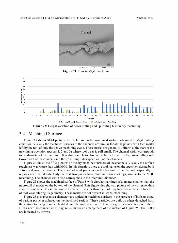
Figure 21: Burr in MQL machining
Figure 22: Height variation of down milling and up milling burr in dry machining
3.4 Machined Surface Figure 23 shows SEM pictures for each pass on the machined surface, obtained in MQL cutting
condition. Visually the machined surfaces of the channels are similar for all the passes, with feed marks left by the tool of only the active machining cycle. These marks are generally uniform at the start of the machining operation (passes 1, 2 and 3) where tool wear is still small. The channel width corresponds to the diameter of the micromill. It is also possible to observe the burrs formed on the down milling side (lower wall of the channel) and the up milling side (upper wall of the channel).
Figure 24 shows the SEM pictures on the dry machined surfaces of the channels. Visually the surface roughness was worse than with MQL. In this situation, there are tool marks on the specimen during both active and inactive periods. There are adhered particles on the bottom of the channel, especially in regions near the laterals. Only the first two passes have more uniform markings, similar to the MQL machining. The channel width also corresponds to the micromill diameter.
Figure 25 shows the machined surface of Pass 8 with circular markings of diameter smaller than the micromill diameter on the bottom of the channel. This figure also shows a picture of the corresponding stage of tool wear. These markings of smaller diameter than the tool may have been made in function of tool wear altering its geometry. These marks are not present in MQL machining.
Figure 25 also presents a characteristic typical of machined surfaces in the presence of built-up edge, of various particles adhered on the machined surface. These particles are built-up edges detached from the cutting tool edges and embedded onto the milled surface. There is a greater concentration of these BUEs near the channel walls. Figure 26 shows an enlargement of the surface of Figure 25. The BUEs are indicated by arrows.
Effect of Cutting Fluid on Micromilling of Ti-6Al-4V Titanium Alloy Ziberov et al.
344

Figure 23: Machined surface in MQL machining
Figure 24: Machined surface in dry machining
Effect of Cutting Fluid on Micromilling of Ti-6Al-4V Titanium Alloy Ziberov et al.
345

Figure 25: Circular markings in dry machining
Figure 26: BUE particles (indicated by arrows)
4 Conclusions The application of cutting fluid improves the quality of the machined surface. This improvement
corresponds to the absence of BUE in MQL machining. However, tool life in dry machining is higher. This is due to the formation of BUE, which in this case protects the cutting wedge of the tool. The tool wear is different for the two conditions. The tool used in MQL machining wears mainly on the secondary clearance face. In dry machining, the tool edge radius increases.
Acknowledgments The authors thank the agencies CAPES, CNPq and FAPEMIG for financial support. Support from
Performance Micro Tools and Unist are appreciated.
Effect of Cutting Fluid on Micromilling of Ti-6Al-4V Titanium Alloy Ziberov et al.
346

References Asad Abma, Takesh M, Rahman M, Lim HS and Wong YS. Tool-based micro-machining. Journal of
Materials Processing Technology 2007; 192: 204-211. Berestovskyi D, Hung NP and Lomeli P. Surface Finish of Ball-End Milled Microchannels. Journal of
Micro- and Nano-Manufacturing 2014; 2: 1-10. Byrne G, Dornfeld D and Denkena B. Advancing cutting technology. CIRP Annals - Manufacturing
Technology 2003; 52(2): 483-507. Camara MA, Campos Rubio JC, Abrao AM and Davim JP. State of the Art on Micromilling of
Materials, a Review. Journal of Materials Science & Technology 2012; 28(8): 673-685. Chae J, Park SS and Freiheit T. Investigation of micro-cutting operations. International Journal of
Machine Tools and Manufacture 2006; 46(3-4): 313-332. Denkena B, Hoffmeister HW and Reichstein M. Micro-machining processes for microsystem
technology. Microsystem Technologies 2006; 12(7): 659-664. Dornfeld D, Min S and Takeuchi Y. Recent advances in mechanical micromachining. CIRP Annals -
Manufacturing Technology 2006; 55(2): 745-768. Fleischer J, Buchholz C and Weule H. Automation of the powder-injection-moulding process for micro-
mechanical parts. CIRP Annals - Manufacturing Technology 2003; 52(1): 419-422. Jackson MJ. Microfabrication AND Nanomanufacturing. EUA: CRC Press Taylor & Francis Group,
2006, ISBN-10: 0-8247-2431-3. Kaminise AK, Ariza RG, Machado ÁR and Da Silva MB. Properties of Burrs Formed When Cutting
AISI 1045 Carbon Steel in Turning Operation. In: Proc. of 7th International Conference on Deburring and Surface Finishing, 2004, pp. 127-135.
Li Q, Lerma I, Edinbarough I, Alvarado J and Hung NP. Characterization of Micromist for Effective Machining. In: Proc. of the ASME 2015 International Mechanical Engineering Congress & Exposition, 2015, pp. 13-19.
Meijer J, Du K, Gillner A, Hoffmann D, Kovalenko VS, Masuzawa T, Ostendorf A, Poprawe R and Schulz W. Laser machining by short and ultrashort pulses, state of the art and new opportunities in the age of the photons. CIRP Annals - Manufacturing Technology 2002; 51(2): 531-550.
Özel T, Liu X and Dhanorker A. Modeling and Simulation of Micro-Milling Process. In: Proc. of the 4th International Conference and Exhibition on Design and Production of Machines and Dies/Molds, 2007, pp. 167-174.
Trent EM and Wright PK. Metal Cutting (4th Ed.), Butterworth, 2000, ISBN: 0-780750-670692.
Effect of Cutting Fluid on Micromilling of Ti-6Al-4V Titanium Alloy Ziberov et al.
347
Related Documents