Effect of cryogenic cooling in milling process of AISI 304 stainless steel Muammer NALBANT 1 , Yakup YILDIZ 2 1. Faculty of Technical Education, Gazi University, 06500 Ankara, Turkey; 2. Department of Machine Education, Gazi University, 06500 Ankara, Turkey Received 17 June 2010; accepted 15 August 2010 Abstract: The effects of cryogenic cooling on cutting forces in the milling process of AISI 304 stainless steel were investigated experimentally. Cryogenic cooling was achieved by spraying liquid nitrogen to tool, chips and material interfaces using a pipe with an internal diameter of 1 mm; the flow rate of liquid nitrogen was 5.2 L/min; two cutting directions (climbing and conventional milling), two machining conditions (dry and cryogenic cooling) and four cutting speeds (80, 120, 160 and 200 m/min) were used in the milling process. Cryogenic cooling and cutting speed are found to be effective on cutting forces. Cutting forces and torque in cryogenic milling are higher than those in dry milling. Cutting force is increased as the cutting speed is increased. Tool fritter around insert nose radius is the main problem of climb milling method in cryogenic cooling at low cutting speeds. Key words: cryogenic cooling; AISI 304; cutting force; tool frittering 1 Introduction Austenitic stainless steel materials, i.e. AISI 304, have been widely used in many areas such as automotive and aerospace industries. AISI 304 austenitic stainless steel is categorized under a group of materials that are very hard to machine. Machining operations of austenitic stainless steels are usually accompanied by a number of difficulties such as poor surface, irregular wear, premature tool failure and built-up-edge (BUE) on the tool flank face and crater face. The presence of BUE will cause an increase in tool wear rate and deteriorate the surface integrity of the work[1í2]. The poor machinability of this material is usually due to very low heat conductivity (50% of that of plain carbon steels), high ductility, high tensile strength, high fracture toughness and high work hardening rate[2í3]. Work hardening of stainless steels results from a severe cutting operation by a worn tool. Work hardening causes increased tool wear and damage rates[4]. The most practical and effective way to enhance the machining performance in cutting difficult-to-cut materials is to reduce the cutting temperature. One way of reducing the cutting temperature is to use a cutting coolant. Cutting fluids are used in conventional machining to extend tool life by reducing tool temperature and friction between the tool, the chip and the workpiece in the cutting process. However, conventional coolants contain different chemicals that may cause water pollution, soil contamination and health problems if disposed without required treatments. Another way of reducing the cutting temperature is to use a cryogenic coolant. Cryogenic machining, in which liquid nitrogen (LN 2 ) is used as a coolant, is considered a viable option to conventional machining. Having a temperature as low as í196 °C at 101.325 kPa, super cold LN 2 is a good coolant. After absorbing the heat dissipated from the cutting process, it evaporates into nitrogen gas and becomes part of the air (79% of the air is nitrogen). It leaves no harmful residue to the environment. Therefore, it is considered to be environment friendly due to this natural recycling[5]. The main functions of cryogenic machining include: 1) removing heat effectively from the cutting zone, hence lowering cutting temperatures, 2) modifying the frictional characteristics at the tool/chip interfaces, and 3) changing the properties of the workpiece and the tool material[6]. In cryogenic machining, different cooling strategies are needed in order to solve the problems specific to the individual materials being machined. In the present work, the authors define cooling strategies as the ways in which the cryogenic coolant is used in the cryogenic machining Corresponding author: Muammer NALBANT; E-mail: [email protected] DOI: 10.1016/S1003-6326(11)60680-8

Welcome message from author
This document is posted to help you gain knowledge. Please leave a comment to let me know what you think about it! Share it to your friends and learn new things together.
Transcript
Effect of cryogenic cooling in milling process of AISI 304 stainless steel
Muammer NALBANT1, Yakup YILDIZ2
1. Faculty of Technical Education, Gazi University, 06500 Ankara, Turkey;
2. Department of Machine Education, Gazi University, 06500 Ankara, Turkey
Received 17 June 2010; accepted 15 August 2010
Abstract: The effects of cryogenic cooling on cutting forces in the milling process of AISI 304 stainless steel were investigated experimentally. Cryogenic cooling was achieved by spraying liquid nitrogen to tool, chips and material interfaces using a pipe with an internal diameter of 1 mm; the flow rate of liquid nitrogen was 5.2 L/min; two cutting directions (climbing and conventional milling), two machining conditions (dry and cryogenic cooling) and four cutting speeds (80, 120, 160 and 200 m/min) were used in the milling process. Cryogenic cooling and cutting speed are found to be effective on cutting forces. Cutting forces and torque in cryogenic milling are higher than those in dry milling. Cutting force is increased as the cutting speed is increased. Tool fritter around insert nose radius is the main problem of climb milling method in cryogenic cooling at low cutting speeds. Key words: cryogenic cooling; AISI 304; cutting force; tool frittering 1 Introduction
Austenitic stainless steel materials, i.e. AISI 304, have been widely used in many areas such as automotive and aerospace industries. AISI 304 austenitic stainless steel is categorized under a group of materials that are very hard to machine. Machining operations of austenitic stainless steels are usually accompanied by a number of difficulties such as poor surface, irregular wear, premature tool failure and built-up-edge (BUE) on the tool flank face and crater face. The presence of BUE will cause an increase in tool wear rate and deteriorate the surface integrity of the work[1 2].
The poor machinability of this material is usually due to very low heat conductivity (50% of that of plain carbon steels), high ductility, high tensile strength, high fracture toughness and high work hardening rate[2 3]. Work hardening of stainless steels results from a severe cutting operation by a worn tool. Work hardening causes increased tool wear and damage rates[4].
The most practical and effective way to enhance the machining performance in cutting difficult-to-cut materials is to reduce the cutting temperature. One way of reducing the cutting temperature is to use a cutting coolant. Cutting fluids are used in conventional machining to extend tool life by reducing tool
temperature and friction between the tool, the chip and the workpiece in the cutting process. However, conventional coolants contain different chemicals that may cause water pollution, soil contamination and health problems if disposed without required treatments. Another way of reducing the cutting temperature is to use a cryogenic coolant. Cryogenic machining, in which liquid nitrogen (LN2) is used as a coolant, is considered a viable option to conventional machining. Having a temperature as low as 196 °C at 101.325 kPa, super cold LN2 is a good coolant. After absorbing the heat dissipated from the cutting process, it evaporates into nitrogen gas and becomes part of the air (79% of the air is nitrogen). It leaves no harmful residue to the environment. Therefore, it is considered to be environment friendly due to this natural recycling[5].
The main functions of cryogenic machining include: 1) removing heat effectively from the cutting zone, hence lowering cutting temperatures, 2) modifying the frictional characteristics at the tool/chip interfaces, and 3) changing the properties of the workpiece and the tool material[6].
In cryogenic machining, different cooling strategies are needed in order to solve the problems specific to the individual materials being machined. In the present work, the authors define cooling strategies as the ways in which the cryogenic coolant is used in the cryogenic machining
Corresponding author: Muammer NALBANT; E-mail: [email protected] DOI: 10.1016/S1003-6326(11)60680-8
Muammer NALBANT, et al/Trans. Nonferrous Met. Soc. China 21(2011) 72 79 73
process to improve the machinability of the materials. These strategies, which may serve different purposes, include: 1) freezing the workpiece, 2) delivering the cryogen to the tool/chip or tool/work interface, 3) cooling the cutting tool, or 4) cooling the chip.
To choose cooling strategies, the properties of both the tool materials and the workpiece materials must be considered because they are fundamental in determining the machining characteristics. The desirable properties of tool materials generally include high hardness and wear resistance, high toughness and strength to resist various forms of fractures, and low chemical affinity with the workpiece. Properties of the workpiece materials become problematic when their hardness and strength are abrasive to cutting tools and these properties cause a high compressive stress to act on the cutting edge, raising the cutting temperatures. The materials’ ductility and toughness affect the chip formation process. Highly ductile materials, for instance, are likely to produce continuous chips and built-up edges[5, 7].
Cryogenic machining of 18 8 stainless steel (SUS27), which is equivalent to AISI 304, has been studied in Japan. And it was reported that the cutting force was increased as the workpiece temperature was decreased to cryogenic temperatures[8].
A milling study by DILLON et al[9] reported an increased difficulty in machining AISI 304 at reduced temperatures. Therefore, AISI 304 is considered to be a poor candidate for successful cryogenic machining. It was stated that if a new cryogenic cooling approach could provide effectiveness in machining this material, it would prevail in cutting other materials[9].
The main objective of the present work is to experimentally investigate the effect of cryogenic cooling with a liquid nitrogen ( 196 °C) nozzle on cutting forces during milling AISI 304 stainless steel. 2 Experimental
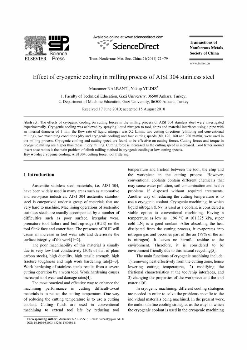
Fig.1 shows the general experimental setup for the measurement of cutting forces and temperature during the cryogenic milling. This setup consists of a cutting force measurement system, a cryogenic cooling system and a liquid nitrogen tank.
Measurements of cutting force along the x, y and z axes (Fx, Fy, Fz) and the torque about the z axis (Mz) are carried out on a Kistler four-component piezoelectric platform type 9123C dynamometer. The rotating cutting force dynamometer can rotate with a speed of up to 10 000 r/min and has a natural frequency of 2 000 Hz. The cutting force measurement system is composed of a stator (Kistler type 52221B1), a connecting cable (Kistler type 1500B19) and a signal conditioner (Kistler type 5223B2) with multiple channels. Data acquisition was
Fig.1 Experimental setup (a) and nozzle apparatus (b) accomplished using DynoWare (Kistler Type 2825D 02) software and an analog to digital converter (Kistler 2855A4 type) with 8 channels. The whole system was checked and calibrated prior to use. The cutting force data were stored in the hard disk of a laptop computer (Fig.1). All cutting force measurements were performed under dry and cryogenic machining conditions.
The liquid nitrogen tank, which is a Taylor-Wharton XL-55HP type tank, has a volume of 198 L. The maximum pressure can be set up to 2 413 kPa (24 bar/350 psig). However, the normal working pressure of the tank was measured to be between 1 720 and 2 413 kPa in the tests. In cryogenic machining, liquid nitrogen jet was delivered from an especially designed nozzle on the interface of tool and workpiece. Cryogenic cooling is an external cooling method making use of a pipe with an internal diameter of 1 mm. The flow rate of liquid nitrogen was 5.2 L/min.
Machining experiments were carried out on Johnford VMC 850 type CNC vertical machining center having 3 axes and a 6 kW DC motor. Its spindle speed can be set up to 3 500 r/min. The workpiece dimensions are 120 mm×120 mm×250 mm.
The chemical composition and the mechanical and thermal properties of AISI 304 work piece materials used in the experiments are shown in Tables 1 and 2, respectively.
The tools used in this study were uncoated cementite carbide inserts having AEMW150308ER geometry and UTI20T grade of Mitsubishi. The grade inserts are suggested by the manufacturing firm for the machining of AISI 304 stainless steel. Mitsubishi
Muammer NALBANT, et al/Trans. Nonferrous Met. Soc. China 21(2011) 72 79 74
Table 1 Chemical composition of AISI 304 stainless steel workpiece (mass fraction, %)
C Si Mn Cr Mo Cu Ni Co P S N
0.017 0.56 1.68 18.23 0.49 0.66 8.2 0.114 0.033 0.026 0.09
Table 2 Physical and thermal properties of AISI 304 stainless steel workpiece
Density/ (kg·m 3)
Elastic modulus/GPa
Poisson ratio
Coefficient of thermal expansion/(10 6 K 1)
Thermal conductivity/(W·K 1·m 1)
Specific heat capacity/(J·kg 1·K 1)
8000 193 0.3 17.8 16.2 500
BAE500R201S20 endmill with single indexable insert was used as a tool holder with a diameter of 24 mm. The cutting width and cutting length were 15 mm and 250 mm, respectively. The cutting depth and feed rate were 0.5 mm and 0.05 mm/r, respectively. Other parameters of face machining are given in Table 3. The cutting tests were carried out according to ISO standard. Dry and cryogenic machining were also performed both in climb and conventional milling. Table 3 Machining parameters and their levels
Level Cutting
condition Cutting
direction Cutting speed/
(m·min 1)
1 Dry Climb 80
2 LN2 Conventional 120
3 160
4 200
Wear photographs of inserts were taken after the
removal of 3 750 mm3 of AISI 304 workpiece material. In wear machining, the cutting length was approximately 218 m. After the wear machining, tool inserts were observed by zooming in 50 times using JOEL JSM 6060 LV type scanning electron microscope.
Full factorial design was used in the machining experiments. Multiple variance analysis was applied to the experimental data using JMP 7.0 statistical software to determine the effects of cutting condition, cutting direction, and cutting speed on the main cutting force. 3 Result and discussion
In milling AISI 304 stainless steel, cutting forces Fx, Fy, Fz and torque Mz measurements were taken by the dynamometer as well as the measurements of the mean, the minimum and the maximum of each force and torque. The machining parameters are the cutting speed of 80 m/min, the spindle speed of 1 273 r/min, the cutting depth of 0.5 mm and the feed rate of 64 mm/min in these tests.
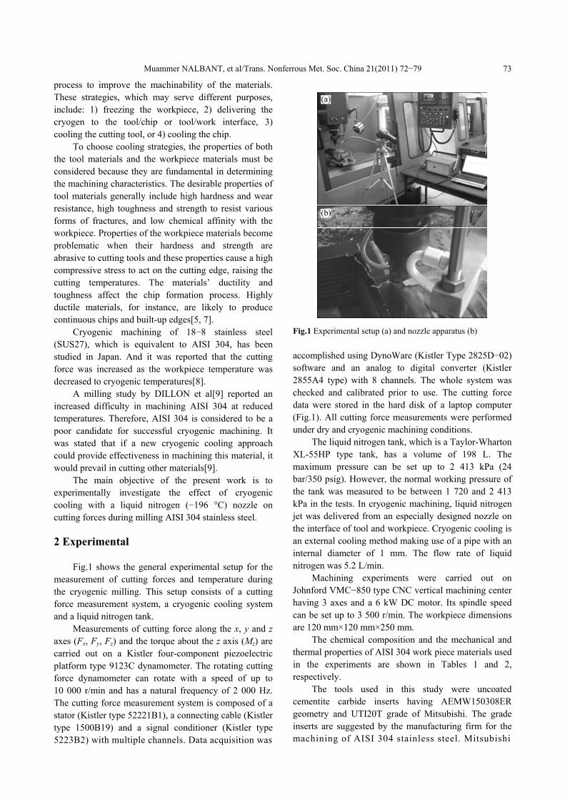
Fig.2(a) shows the plot of Fx versus cutting speed in the cryogenic and dry milling. The results show that in
the cryogenic milling and dry milling, Fx increases slightly with increasing cutting speed. The maximum Fx in cryogenic milling is higher than that in dry milling. The average Fx in cryogenic milling is higher by 6.5% than that in dry milling.
The change of Fy with cutting speed is given in Fig.2(b). It shows an increase in Fy in both the cryogenic and dry milling. The maximum Fy in cryogenic milling is higher than that in dry milling. The average Fy in cryogenic milling is higher by 5.6% than that in dry milling. Also, Fy increases with increasing cutting speed.
Fig.2(c) shows the plot of Fz versus cutting speed in the cryogenic and dry milling. The graph shows that Fz increases with increasing cutting speed in the cryogenic milling and dry milling. The maximum Fz in cryogenic milling is higher than that in dry milling. The average Fz in cryogenic milling is higher by 3.3% than that in dry milling.
The measured maximum cutting forces are comparable to each other. The maximum cutting forces are ordered from higher to lower as Fx>Fz>Fy in the milling of AISI 304 stainless steel. This order is proper to cutting distances.
Fig.2(d) shows a decrease in Mz with an increase in the cutting speed. The maximum Mz in dry milling is lower than that in cryogenic milling. There is a difference of 7.9% in the Mz maximum values between cryogenic and dry milling.
Multiple variance analysis is also applied to the cutting force data obtained from milling AISI 304 stainless steel. The experimental data were interpreted by factorial design of 2×2×4 (2 cutting directions, 2 cutting conditions, 4 cutting speeds). Only the main factors’ effects were considered in the variance analysis.
The results of variance analysis of maximum Fx are given in Table 4. According to the results of ANOVA, the cutting direction and cutting condition are the significant parameters affecting the Fx (P<0.05). However, the cutting speed does not affect the maximum Fx.
The results of variance analysis of the maximum Fy are given in Table 5. According to the results of ANOVA, the cutting condition and the cutting speed are the
Muammer NALBANT, et al/Trans. Nonferrous Met. Soc. China 21(2011) 72 79 75
Fig.2 Measured cutting force and torque versus cutting speed in cryogenic and dry milling: (a) Fx; (b) Fy; (c) Fz force; (d) Mz Table 4 Variance analysis of the maximum Fx
Source fSum of square
Mean square
F value
Probability>F
Cutting direction
1 494.95 494.95 8.01 0.017
Cutting condition
1 307.56 307.56 4.97 0.049
Cutting speed 3 156.54 52.18 0.84 0.500
Error 10 617.96 61.79
Total 15 1 577.02
significant parameters affecting the maximum Fy (P<0.05). However, the cutting direction does not affect the maximum Fy.
The results of variance analysis of the maximum Fz are given in Table 6. According to the results of ANOVA, the cutting speed, cutting direction and cutting condition do not affect the maximum Fz (P<0.05).
The results of variance analysis of maximum Mz are given in Table 7. According to the results of ANOVA, the cutting condition and cutting speed are the significant parameters affecting the maximum Mz (P<0.05). However, the cutting direction does not affect the maximum Mz.
Table 5 Variance analysis of the maximum Fy
Source fSum of square
Mean square
Fvalue
Probability>F
Cutting direction
1 39.56 39.56 0.31 0.591
Cutting condition
1 926.28 926.28 7.18 0.023
Cutting speed 3 2009.90 669.96 5.19 0.020
Error 10 1288.48 128.84
Total 15 4264.2403
Table 6 Variance analysis of the maximum Fz
Source fSum of square
Mean square
F value
Probability>F
Cutting direction
1 295.06 295.06 1.78 0.211
Cutting condition
1 261.22 261.23 1.57 0.237
Cutting speed 3 438.14 146.05 0.88 0.482
Error 10 1 654.33 165.43
Total 15 2 648.76
Muammer NALBANT, et al/Trans. Nonferrous Met. Soc. China 21(2011) 72 79 76
The cutting forces in cryogenic milling are higher than those in dry cutting, which are parallel to the data obtained by some researchers[7 9]. Cryogenic machining tends to increase the cutting force because the working material becomes harder and stronger at lower temperatures. The hardness of the material was measured
Table 7 Variance analysis of the maximum Mz
Source fSum of square
Mean square
Fvalue
Probability>F
Cutting direction
1 0.52 0.52 0.42 0.531
Cutting condition
1 8.59 8.59 6.91 0.025
Cutting speed 3 16.64 5.55 4.46 0.031
Error 10 12.44 1.24
Total 15 38.20
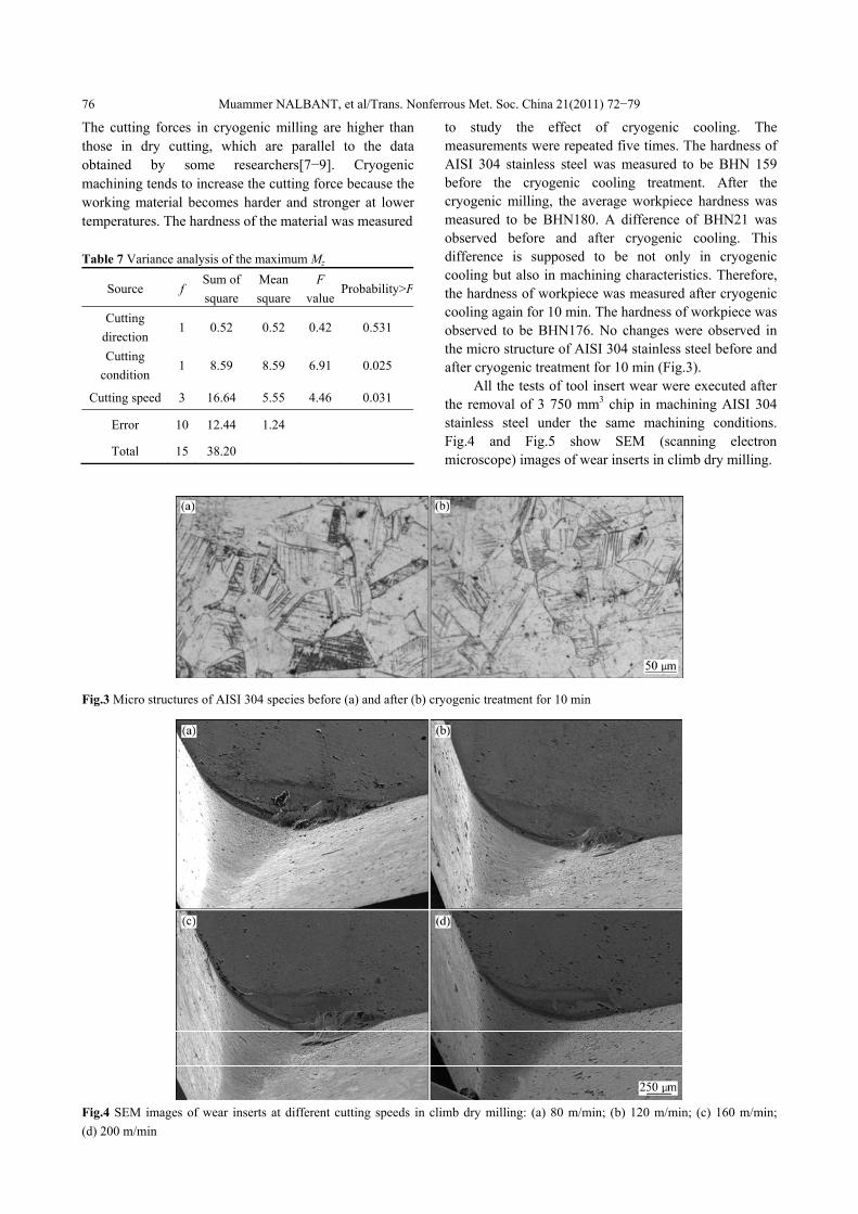
to study the effect of cryogenic cooling. The measurements were repeated five times. The hardness of AISI 304 stainless steel was measured to be BHN 159 before the cryogenic cooling treatment. After the cryogenic milling, the average workpiece hardness was measured to be BHN180. A difference of BHN21 was observed before and after cryogenic cooling. This difference is supposed to be not only in cryogenic cooling but also in machining characteristics. Therefore, the hardness of workpiece was measured after cryogenic cooling again for 10 min. The hardness of workpiece was observed to be BHN176. No changes were observed in the micro structure of AISI 304 stainless steel before and after cryogenic treatment for 10 min (Fig.3).
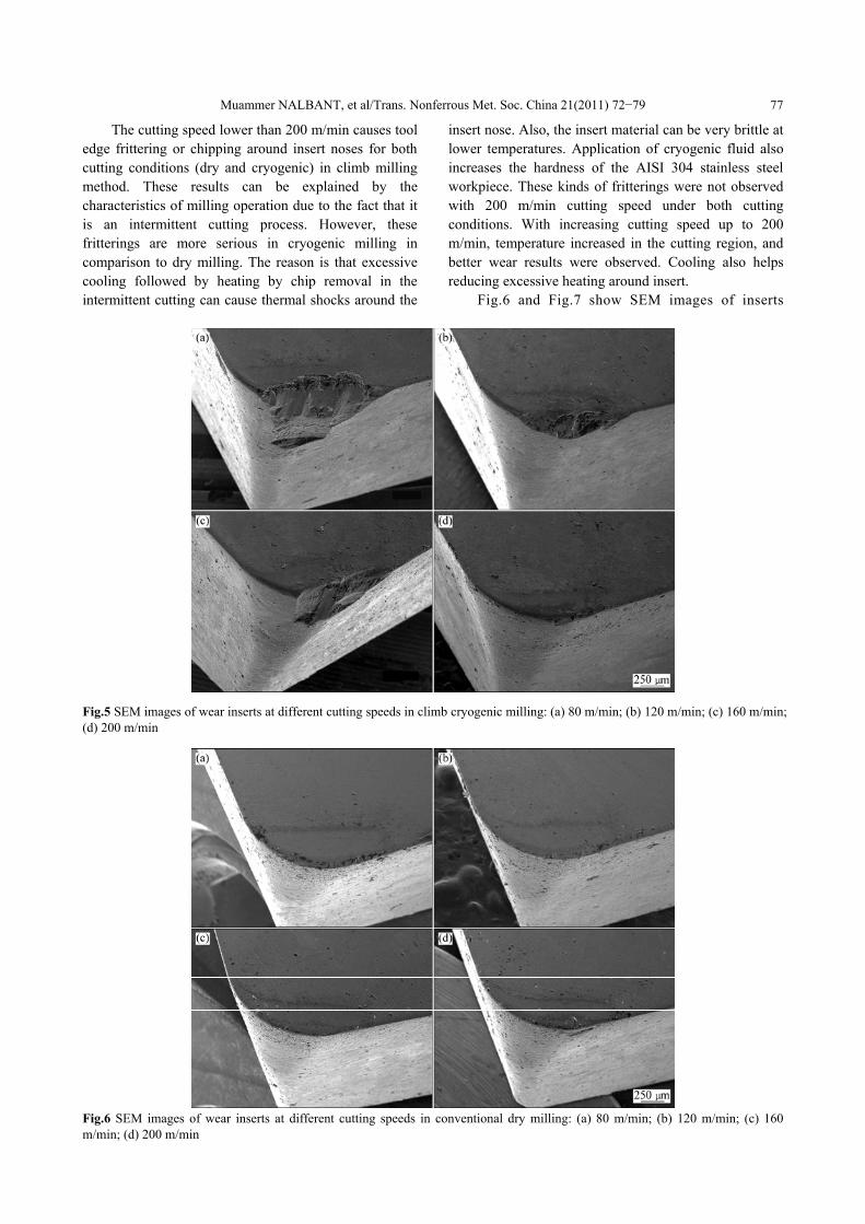
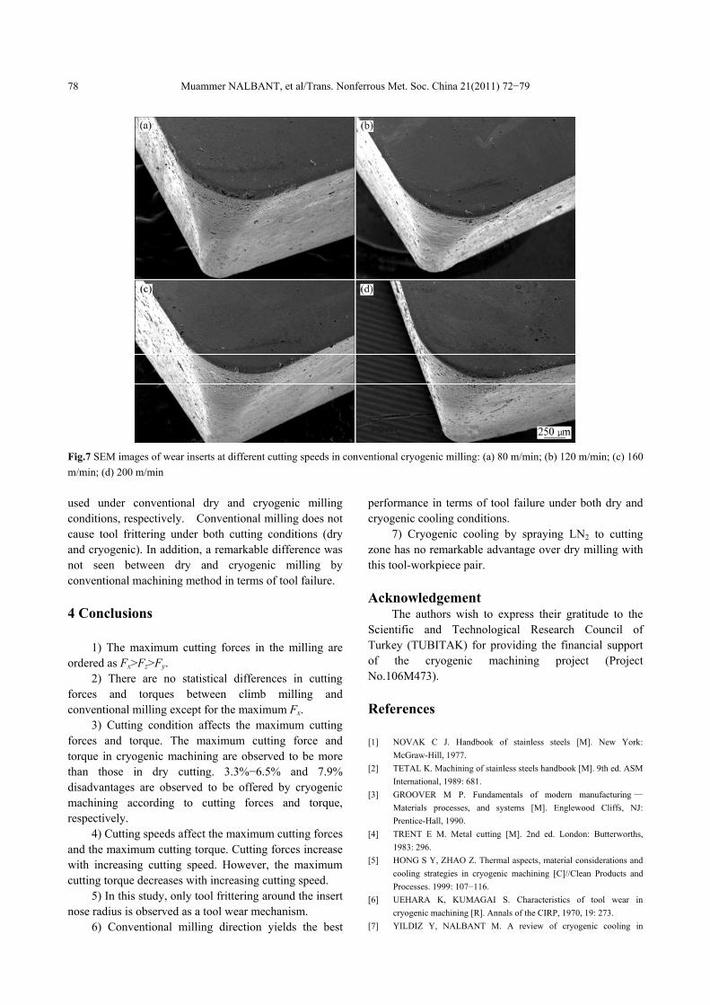
All the tests of tool insert wear were executed after the removal of 3 750 mm3 chip in machining AISI 304 stainless steel under the same machining conditions. Fig.4 and Fig.5 show SEM (scanning electron microscope) images of wear inserts in climb dry milling.
Fig.3 Micro structures of AISI 304 species before (a) and after (b) cryogenic treatment for 10 min
Fig.4 SEM images of wear inserts at different cutting speeds in climb dry milling: (a) 80 m/min; (b) 120 m/min; (c) 160 m/min; (d) 200 m/min
Muammer NALBANT, et al/Trans. Nonferrous Met. Soc. China 21(2011) 72 79 77
The cutting speed lower than 200 m/min causes tool edge frittering or chipping around insert noses for both cutting conditions (dry and cryogenic) in climb milling method. These results can be explained by the characteristics of milling operation due to the fact that it is an intermittent cutting process. However, these fritterings are more serious in cryogenic milling in comparison to dry milling. The reason is that excessive cooling followed by heating by chip removal in the intermittent cutting can cause thermal shocks around the
insert nose. Also, the insert material can be very brittle at lower temperatures. Application of cryogenic fluid also increases the hardness of the AISI 304 stainless steel workpiece. These kinds of fritterings were not observed with 200 m/min cutting speed under both cutting conditions. With increasing cutting speed up to 200 m/min, temperature increased in the cutting region, and better wear results were observed. Cooling also helps reducing excessive heating around insert.
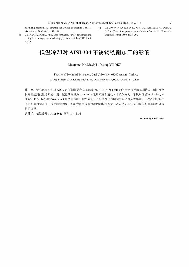
Fig.6 and Fig.7 show SEM images of inserts
Fig.5 SEM images of wear inserts at different cutting speeds in climb cryogenic milling: (a) 80 m/min; (b) 120 m/min; (c) 160 m/min; (d) 200 m/min
Fig.6 SEM images of wear inserts at different cutting speeds in conventional dry milling: (a) 80 m/min; (b) 120 m/min; (c) 160 m/min; (d) 200 m/min
Muammer NALBANT, et al/Trans. Nonferrous Met. Soc. China 21(2011) 72 79 78
Fig.7 SEM images of wear inserts at different cutting speeds in conventional cryogenic milling: (a) 80 m/min; (b) 120 m/min; (c) 160 m/min; (d) 200 m/min used under conventional dry and cryogenic milling conditions, respectively. Conventional milling does not cause tool frittering under both cutting conditions (dry and cryogenic). In addition, a remarkable difference was not seen between dry and cryogenic milling by conventional machining method in terms of tool failure. 4 Conclusions
1) The maximum cutting forces in the milling are ordered as Fx>Fz>Fy.
2) There are no statistical differences in cutting forces and torques between climb milling and conventional milling except for the maximum Fx.
3) Cutting condition affects the maximum cutting forces and torque. The maximum cutting force and torque in cryogenic machining are observed to be more than those in dry cutting. 3.3% 6.5% and 7.9% disadvantages are observed to be offered by cryogenic machining according to cutting forces and torque, respectively.
4) Cutting speeds affect the maximum cutting forces and the maximum cutting torque. Cutting forces increase with increasing cutting speed. However, the maximum cutting torque decreases with increasing cutting speed.
5) In this study, only tool frittering around the insert nose radius is observed as a tool wear mechanism.
6) Conventional milling direction yields the best
performance in terms of tool failure under both dry and cryogenic cooling conditions.
7) Cryogenic cooling by spraying LN2 to cutting zone has no remarkable advantage over dry milling with this tool-workpiece pair. Acknowledgement
The authors wish to express their gratitude to the Scientific and Technological Research Council of Turkey (TUBITAK) for providing the financial support of the cryogenic machining project (Project No.106M473). References [1] NOVAK C J. Handbook of stainless steels [M]. New York:
McGraw-Hill, 1977. [2] TETAL K. Machining of stainless steels handbook [M]. 9th ed. ASM
International, 1989: 681. [3] GROOVER M P. Fundamentals of modern manufacturing
Materials processes, and systems [M]. Englewood Cliffs, NJ: Prentice-Hall, 1990.
[4] TRENT E M. Metal cutting [M]. 2nd ed. London: Butterworths, 1983: 296.
[5] HONG S Y, ZHAO Z. Thermal aspects, material considerations and cooling strategies in cryogenic machining [C]//Clean Products and Processes. 1999: 107 116.
[6] UEHARA K, KUMAGAI S. Characteristics of tool wear in cryogenic machining [R]. Annals of the CIRP, 1970, 19: 273.
[7] YILDIZ Y, NALBANT M. A review of cryogenic cooling in
Muammer NALBANT, et al/Trans. Nonferrous Met. Soc. China 21(2011) 72 79 79
machining operations [J]. International Journal of Machine Tools & Manufacture, 2008, 48(9): 947 964.
[8] UEHARA K, KUMAGAI S. Chip formation, surface roughness and cutting force in cryogenic machining [R]. Annals of the CIRP, 1968, 17: 409.
[9] DILLON O W, ANELIS D, LU W Y, GUNASEKERA J S, DENO J A. The effects of temperature on machining of metals [J]. J Materials Shaping Technol, 1990, 8: 23 29..
AISI 304
Muammer NALBANT1, Yakup YILDIZ2
1. Faculty of Technical Education, Gazi University, 06500 Ankara, Turkey;
2. Department of Machine Education, Gazi University, 06500 Ankara, Turkey
AISI 304 1 mm
5.2 L/min 2 2
80 120 160 200 m/min 4
AISI 304
(Edited by YANG Hua)
Related Documents