Final Report EASA_REP_RESEA_2014_1 Research Project: EFB Electronic Flight Bag Aircraft performance calculations and mass & balance Best practices for evaluation and use of EFB

Welcome message from author
This document is posted to help you gain knowledge. Please leave a comment to let me know what you think about it! Share it to your friends and learn new things together.
Transcript

Final Report EASA_REP_RESEA_2014_1
Research Project:
EFB
Electronic Flight Bag
Aircraft performance calculations and mass & balance
Best practices for evaluation and use of EFB

Disclaimer
This study has been carried out for the European Aviation Safety Agency by an external organization and expresses the opinion of the organization undertaking the study. It is provided for information purposes only and the views expressed in the study have not been adopted, endorsed or in any way approved by the European Aviation Safety Agency. Consequently it should not be relied upon as a statement, as any form of warranty, representation, undertaking, contractual, or other commitment binding in law upon the European Aviation Safety Agency.
Ownership of all copyright and other intellectual property rights in this material including any documentation, data and technical information, remains vested to the European Aviation Safety Agency. All logo, copyrights, trademarks, and registered trademarks that may be contained within are the property of their respective owners.
Reproduction of this study, in whole or in part, is permitted under the condition that the full body of this Disclaimer remains clearly and visibly affixed at all times with such reproduced part.

Best practices for approval of Performance and MB applications on EFBs Final Report R.S. Tump, G.W.H. van Es, A.K. Karwal and M.J. Verbeek
C u s t o m e r EASA October 2015

Best practices for approval of Performance and MB applications on EFBs
2 | NLR-CR-2015-354
No part of this report may be reproduced and/or disclosed, in any form or by any means without the prior
written permission of the owner.
Customer EASA Contract number EASA.2014.C06 Owner NLR Division NLR Air Transport Distribution Limited Classification of title Unclassified Date October 2015 Approved by:
Author R.S. Tump
Reviewer A.K. Karwal
Managing department R.C.J. Ruigrok
Date 15 Oct 2015 Date Date

NLR-CR-2015-354 | 3
Summary In recent years, the usage of EFBs to assist pilots with their cockpit task has increased considerably. Many hardware and software applications are nowadays present on the aviation market. In consequence to an increasing trend in the use of portable EFB systems, National Aviation Authorities (NAAs) have witnessed increasing demand with respect to EFB approvals and, thus, an increasing requirement in the necessary expertise with which to accomplish this task. Development of standardised evaluation procedures will support the successful realisation and maintenance of high-levels of safety by EASA Member States. The objective of this project was to perform a study to select the best available evaluation practices currently used by national authorities for granting EFB approvals, and proposing clear evaluation guidelines and readily usable recommendations for developing standardised EFB approval procedures with respect to performance and mass & balance software. The survey distributed among European Regulators had a limited response; however, information on the present NAA approval procedures was obtained. The compliance process as described in AMC 20-25 is adequate according most NAAs, however, the NAAs reported on several difficulties during the approval process and made recommendations for the future approval process. In general, all NAA addressed the operator’s approval request using in house expertise to assess compliance with AMC 20-25. It showed that NAAs put special attention on different areas. NLR performed a hazard identification and risk assessment of risks associated with the use of (Take-off and Landing) Performance and Mass Balance applications on EFBs. This assessment contains the unmitigated risks. The objective of this NLR assessment was to provide insight into areas where risks may be present, information a Regulator may use while assessing the operator risk assessment. Second objective was to provide a guideline for the Regulator on the number of mitigating measures that should be in place at the operator. After assessing the Regulators’ approval procedures described in the survey responses and interviews a deduction of “best practice” was not feasible. However, based on the contractor’s in-house expertise on flight operational and certification aspects, in combination with the survey and interviews, guidance has been derived and documented in this report that can be used for the EFB operational approval process. This includes, among others, the Regulator’s familiarization with the product and establishment of terms of reference with the Operator, using the NLR risk assessment and, test guidelines to support verification of performance calculation algorithms.
Regulators should be made aware that errors in pilot entry into EFB applications are the most common factor in EFB-related incidents. EASA should consider performing uninvited (e.g. initiated by EASA) and limited-scope (not a full OEB process) evaluations of commercially available TALP/MB applications targeted only at Human Factors issues. EASA is encouraged to distribute the developed hazard and proposed mitigation measure list to Regulators or to include it in the ICAO EFB manual. This will provide raised awareness into areas where risks may be present and provide guidelines on mitigating measures.

4 | NLR-CR-2015-354
Best practices for approval of Performance and MB applications on EFBs

NLR-CR-2015-354 | 5
Content Abbreviations 7
1 Introduction 9
1.1 Project tasks described in this report 9 1.1.1 Literature review 9 1.1.2 Survey and assessment of existing procedures 9 1.1.3 Hazard assessment of TALP and MB EFB applications 9 1.1.4 Assessment of best practices and NAA support tool 9 1.1.5 Recommendations 9
2 Literature review 10
2.1 Summary 10 2.2 Review content 10
3 Survey of existing approval procedures at NAAs 15
3.1 General 15 3.2 Integral survey content 15 3.2.1 General (Q1-4) 15 3.2.2 Type of operation and applications (Q5-9) 15 3.2.3 Reference documents used by NAA (Q10) 16 3.2.4 Special attention (Q13) 16 3.2.5 Test sessions and in-service events (Q14, Q16-17) 16 3.2.6 Difficulties encountered and lessons learned (Q11-12) 16 3.2.7 Recommendations (Q15) 18 3.2.8 Further interviews (Q18) 19 3.3 Analysis of the survey response 19
4 Interviews taken at NAAs 21
4.1 General 21 4.2 Interview ILenT 21 4.3 Interview DGAC 21 4.4 Concluding remarks on the NAA interviews 21
5 EFB hazard assessment 23
5.1 Aircraft Performance 23

6 | NLR-CR-2015-354
Best practices for approval of Performance and MB applications on EFBs
5.2 Weight & Balance Data 25 5.3 Performance and weight & balance related hazards using an EFB 26 5.3.1 Take-off and landing performance calculation related hazards and consequences 27 5.3.2 Weight & balance calculation related hazards and consequences 28 5.4 Hazards from brainstorm session 30 5.5 Hazard effect analysis 30
6 EFB operational approval process 32
6.1 Assessment of best practices 32 6.2 Gaps in NAA approval process from a risk assessment perspective 33 6.3 A generic process for the verification of EFB performance calculations 34 6.3.1 Process of checking EFB performance and weight & balance results 34 6.3.2 Guidelines for selecting test points 40 6.3.3 Guidelines for performance database management 43
7 Support tool for assessing operators Risk Assessment 44
7.1 Mitigating measures 44 7.2 Level of Attention Required (LAR) 44 7.3 List of hazards, LAR and mitigating strategies 46
8 Recommendations 51
9 References 53
Appendix A Survey form 54
Appendix B Interview IlenT 58
Appendix C Interview DGAC 60
Appendix D Mom NLR Brainstorm session 63
Appendix E Integral list of hazard and LAR 70

NLR-CR-2015-354 | 7
Abbreviations
Acronym Description AMC Acceptable Means of Compliance
EASA European Aviation Safety Agency
EFB Electronic Flight Bag
HW Hardware
NAA National Aviation Authority
NLR National Aerospace Laboratory NLR
OEB Operational Evaluation Board
R&D Research and Development
SOP Standard Operating Procedure
SW Software

8 | NLR-CR-2015-354
Best practices for approval of Performance and MB applications on EFBs
This page is intentionally left blank.

NLR-CR-2015-354 | 9
1 Introduction
1.1 Project tasks described in this report This report contains the results of the EASA EFB project. In the next subsections a short
introduction per executed project task is given.
1.1.1 Literature review A literature analysis and review has been conducted that provided operational, regulatory,
opinion-related and scientific reference material from a variety of sources. The study contains
documentation on operational application of EFBs (e.g. EASA AMC 20-25, FAA AC-120-76C),
aviation software (developments), hardware (developments) by EFB OEMs and aircraft
manufacturers and operational incidents and accidents with respect to EFB usage.
The output of task 1 is given in Chapter 2.
1.1.2 Survey and assessment of existing procedures In this task, a questionnaire has been produced and sent out to NAAs to obtain information on
existing operation approval methods by NAA’s. Furthermore interviews have been taken at two
selected NAAs. The results1 will be used to assess best-practices in task 6. The output of task 2 is
given in Chapter 3 and 4.
1.1.3 Hazard assessment of TALP and MB EFB applications Task 3 of the project embodied the hazard assessment of take-off and landing performance and
Mass and Balance EFB applications. The assessment contains an identification of hazards, their
effect and estimation of “likelihood” by introducing two failure types. The output of this task 3 is
given in Chapter 5.
1.1.4 Assessment of best practices and NAA support tool Task 4 of the project embodied the selection of best practices of EFB approval methods and the
establishment of an NAA support tool. This output is given in Chapter 6 and 7.
1.1.5 Recommendations The project recommenadtions are given in Chapter 8.
1 According to the project requirements, a comparison between the NAA approval processes should be made. However, due to the relatively low response and limited in-depth information provided by the NAA’s, the comparison is given in the form of a summarizing chapter 3.

10 | NLR-CR-2015-354
Best practices for approval of Performance and MB applications on EFBs
2 Literature review
2.1 Summary The literature review includes the analysis of material from:
• Accidents/incidents reports
• Safety assessment reports
• Software/hardware
• EASA EFB workshop
• Operational Evaluations
• Certification Plan
• Other
In the accidents and incidents reports most frequently the main identified causal factor is Human
Factors. Two main Human Machine Interface elements can be identified: Pilot data entry errors
and presentation of critical performance calculation (assumptions) lacking or being unnoticed by
the crew.
2.2 Review content Documentation on operational application of EFBs:
• EASA AMC 20-25 • FAA AC-120-76C • ICAO ANNEX 6 AMD38 • CASA CAAP233-1 • (JAA TGL-36)
Above documentation does not offer a methodology to approve performance functionalities and associated performance databases. E.g., in AMC 20-25, only high-level guidance is given. HMI-, reliability- and accuracy testing is prescribed, but it is not described how such testing should be performed. The text is rather subjective and therefor particularly open to different interpretations/methods. E.g., in AMC 20-25 section F1.2.1, subjective words like “appropriate”, “representative” and “sufficient” are frequently used. For each accident, incident and safety assessment report below, the main causal factors or focus is given. Accidents/incidents
• Investigation reports Investigation reports on performance/W&B related accidents/incidents are given below.
o a04h0004 (B747 Halifax Oct 2004) Main causal factor: Human Factors – wrong take-off weight used

NLR-CR-2015-354 | 11
o AAIB Bulletin 4-2013 (B737 Chambery Apr 2012) Main causal factor: Human Factors – wrong take-off weight used (on exiting standby mode, EFB retained take-off weight from last flight)
o AAIB Bulletin 7-2010 (A340 London Dec 2009) Main causal factor: Human Factors – landing weight used for take-off weight
o AAIB Bulletin 11-2009 (A330 Montego Bay Oct 2008) Main causal factor: Human Factors – wrong take-off data used. It has not been possible to determine the exact cause of the error.
o AAIB Bulletin 7-2009 (B767 Manchester Dec 2008) Main causal factor: Human Factors - The zero fuel weight (ZFW) had been incorrectly entered into the operator’s Computer Take Off Programme1 (CTOP) instead of the takeoff weight (TOW).
o ATSB Presentation (A340 Melbourne Mar 2009) Main causal factor: Human Factors – wrong take-off weight entered.
o ATSB Transport Safety Report AO-2009-012 (A340 Melbourne Mar 2009) Main causal factor: Human Factors – wrong take-off weight entered.
o DAAIB HCL49-99 (B767 Copenhagen Aug 1999) Main causal factor: Human Factors – The flight crew used a wrong and too low value as input take-off weight.
o “Serious incident on 16 August 2008 on take-off from Paris Charles de Gaulle Airport (95) to the Boeing 737-800 registered SU-BPZ operated by AMC Airlines”, Report, BEA Main causal factor: Human Factors – The crew did not take into account the reduction in the length of the runway caused by the works under way and the takeoff distance calculated by the OPT was not known to the crew.
o “Runway Overrun and Collision, Southwest Airlines Flight 1248, Boeing 737-7H4, N471WN, Chicago Midway International Airport, Chicago, Illinois, December 8, 2005”, NTSB/AAR-07/06, October, 2007 Main causal factor: Human Factors – Contributing to the accident were Southwest Airlines’ 1) failure to provide its pilots with clear and consistent guidance and training regarding company policies and procedures related to arrival landing distance calculations; 2) programming and design of its on board performance computer, which did not present inherent assumptions in the program critical to pilot decision-making.
• Safety assessment reports
o Johnstone, N., “The Electronic Flight Bag Friend or Foe”, Air Safety Group Report Nr 104, February 2013 Focus: Amongst others, this report mentions some interesting software errors due to poor program design.
o “Take-off performance calculation and entry errors - a global perspective”, ATSB Transport Safety Report AR-2009-052, 2011. Focus: HF/HMI.
o “Use of Erroneous Parameters at Take-Off”, DGAC DOC AA556-2008, May 2008. Focus: HF/HMI.

12 | NLR-CR-2015-354
Best practices for approval of Performance and MB applications on EFBs
Chandra, D.C., Kendra, A., “Review of Safety Reports Involving Electronic Flight Bags”, DOT/FAA/AR-10/5, DOT-VNTSC-FAA-10-08, April 2010. Focus: HF/HMI.
o “Flight Crew Computer Errors (FMS, EFB) Case Studies”, IATA, 1st ed., October 2011. Case studies including those listed above under Investigation reports. Focus: Mostly data entry errors.
o Berman, A.B., Dismukes, R.K., Jobe, K.K., “Performance Data Errors in Air Carrier Operations: Causes and Countermeaures”, NASA/TM—2012–216007, June 2012. Focus: HF/HMI.
o Mariani, C., “Risk Analysis in Take-Off Procedure with Electronic Flight Bag”, thesis, 2011/2012. Focus: Risk assessment methods.
o Puig, S., “The Take-Off Securing function” in “Safety First – The Airbus Safety Magazine”, #8, pg. 10-16, July 2009. Focus: Description of Airbus’ Take-Off Securing function (TOS).
Software/hardware • Gabree, S., Yeh, M., Jo, Y.J., “Electronic Flight Bag (EFB): 2010 Industry Survey”, DOT-
VNTSC-FAA-10-14, September 2010. • Kemmetmueller, A., “The Value of Back Office Integration – Electronic Flight Bag (EFB)
White Paper”, IMDC, (>2010?). • “Aircraft IT Operations”, e-Journals,
http://www.aircraftit.com/Operations/eJournals.aspx
EASA EFB Workshop
• 01 EFBWShop_ESI_Introduction_ 18 Apr 13 • 02 EFBWShop_Chairman RG_ 18 Apr 13_rev FTom • 03 EFBWShop_RSalgues_AMC 20-25_revFTom • 04 HJU presentation RAG-SSCC 18 APR_rev FTom • 05 EFBWShop_MVE_ 18 Apr 13 • 06 EFBWShop_FRU_ETSO-C165a_18 Apr 13 • 07 EFB Workshop-Manufacturers_Viewpoint_Final • 08 EFB Workshop_operators • 09 EASA EFB Workshop 18APR13 ECA Presentation • 10 EFB Workshop_UK CAA • 11 EFBWShop_A.Hervé_Exp in FR_ 18 Apr 13 • 12 EFB WShop_FAA_2013.03.20.01 • 13 EFBWShop_FTom_RMT.0001_18 Apr 13_rev 2

NLR-CR-2015-354 | 13
Operational evaluation • “Airbus - A380 - Class 3 EFB (OIS1b) with Documentation and Performance Software”,
EASA, November 2008 • “ATR “ Class 2 EFB with performance calculation“”, EASA, August 2013 • “ELECTRONIC FLIGHT BAG (EFB) EVALUATION REPORT - BOEING CLASS 3 EFB & CMA-
1410 Class 3 EFB”, EASA, rev.1.3, March 2014 • “Dassault - All EASy Cockpits - Class 2 EFB with JeppView/FlightDeck as backup avionics”,
EASA, August 2011 • “Dassault Falcon - 7X - Electronic Performance Module for Class 2 EFB”, interim report,
EASA, July 2012 • “FlySmart with Airbus for iPad - V2”, EASA, December 2013 • “Gael Ltd. Q-Pulse Docs (iOS) (v1.48)”, EASA, February 2014 • “Dassault - All EASy Cockpits - Class 1 EFB with Jeppesen Mobile TC / FD iOS”, EASA,
interim report, October 2012 • “Jeppesen FliteDeck Pro (iOS) (v1.1)/Jeppesen Mobile TC Pro (iOS) (v1.3)”, EASA, October
2012 • “Navtech iCharts (12.7) for iOS”, EASA, June 2013
Certification Plan
• Stil, J.G., “Certification Plan for the KDC-10 Electronic Take-Off & Landing Data Tool”, NLR-CR-2014-123, June 2014
Other performance related studies
• Es, G.W.H. van, “A STUDY OF RUNWAY EXCURSIONS FROM A EUROPEAN PERSPECTIVE”, NLR-CR-2010-259, May 2010
• Simpson, P., “Approach and Landing - TEM Analysis”, Kai Talk, Issue 1, 2008 • Comfort, G., “RuFAB – Runway friction characteristics measurement and aircraft braking
– Volume I – Summary of Findings and Recommendations”, Research Project EASA.2008/4, EASA, March 2010
• Santoni, F., Terhune, J., “ERRONEOUS TAKEOFF”, Boeing Flight Operations, No.11, July 2000
• “Reducing the Risk of Runway Excursions”, Report of the Runway Safety Initiative, Flight Safety Foundation, May 2009
• Es, G.W.H. van, “LANDING LONG: WHY DOES IT HAPPEN?”, NLR-TP-2011-120, March 2011
• Es, G.W.H. van, e.a., “Safety aspects of aircraft performance on wet and contaminated runways”, NLR-TP-2001-216, May 2001
• Zontul, M., “Rule Based Aircraft Performance System”, International Journal of Soft Computing and Engineering (IJSCE) ISSN: 2231-2307, Volume-3, Issue-4, September 2013
• Es, G.W.H. van, “Running out of runway - Analysis of 35 years of landing overrun accidents”, NLR-TP-2005-498, September 2005
• “Report on the Design and Analysis of a Runway Excursions Database - A Research Project Conducted for the Flight Safety Foundation”, Safety Management Specialties, May 2009

14 | NLR-CR-2015-354
Best practices for approval of Performance and MB applications on EFBs
• Sonntag, D., “Beyond the Threshold: Lessons from Landing Excursions”, Originally submitted as part of the requirement for the award of MSc in Air Safety Management at City University, London, July 2010
• “Performance Optimization”, Position Paper 07/4, Dutch Air Line Pilots Association, September 2007
• Other material
• Takahashi, T.T., “Federal Regulation of Electronic Flight Bags”, AIAA 2012-5676, 12th AIAA Aviation Technology, Integration, and Operations (ATIO) Conference and 14th AIAA/ISSM, 17 - 19 September 2012, Indianapolis, Indiana
• “Aircraft EFB Users Forum (EFB UF)”, ARINC Project Initiation/Modification (APIM), March 2014
• Bellamy III, W., “Electronic Flight Bags: Big Improvements, Bright Future”, Avionics Today, July 1, 2014
• Theunissen, E., e.a., “EVALUATION OF AN ELECTRONIC FLIGHT BAG WITH INTEGRATED ROUTING AND RUNWAY INCURSION DETECTION FUNCTIONS”, IEEE, 2005
• Chandra, D.C., e.a., “Human Factors Considerations in the Design and Evaluation of Electronic Flight Bags (EFBs)”, DOT/FAA/AR-03/67 DOT-VNTSC-FAA-03-07, Version 2, September 2003
• “Benefits of EFB Technology”, Positioning Paper, SITA, 2012 • Chandra, D., Yeh, M., “Evaluating Electronic Flight Bags in the Real World”, John A. Volpe
National Transportation Systems Center, Cambridge, MA, 2007 • Spannenburg, A.M., “Requirements Elicitation and Solution Specification for an Electronic
Flight Bag”, Master’s Thesis, University of Twente, Enschede, the Netherlands, August 2011
• “Aircraft e-enablement Strategy Paper”, version 1.2, Star Aliance, August 2012 • “Position Paper on Electronic Charting (eCharts) - Application”, Star Aliance, May 2010 • “Position Paper on Electronic Flight Bag (EFB) and aircraft data”, Star Aliance, May 2010 • “Position Paper on Electronic Flight Folder - Application”, Star Aliance, November 2009 • “Flight Operations Requirements for electronic Logbook (eLog) - Application”, Star
Aliance, November 2009

NLR-CR-2015-354 | 15
3 Survey of existing approval procedures at NAAs
3.1 General Of twenty-nine survey questionnaires distributed to NAAs, eleven replies were received by NLR,
one of which was from a major NAA. This was after a personal reminder was sent to all contact
persons at the NAAs. A summary of the responses is given below, with reference to the survey
questionnaire numbering. The questionnaire can be found in Appendix A.
3.2 Integral survey content 3.2.1 General (Q1-4) Three NAAs did not want to be referenced as participant to the project. Eight NAAs did have
experience in approving EFB Performance and/or MB applications. The number of approvals on
portable EFB applications varied from 1 to more than 15, the number on fixed EFBs varied from
zero to five. Most approvals have been granted in the years 2010-2015.
3.2.2 Type of operation and applications (Q5-9) The type of operators varied from; major airline, regional airline, business operator cargo
operator to small operators. The aircraft types included:
A320, A330, A340, A380, G200, G550, MD80, DA42, EMB135/145, EMB170, EMB190, C550,
C525B, C56X, C525, C560XL, Challenger300, Chalenger605, CRJ900, BEECHCRAFT PR.1A, BE 30,
LEARJET60 & LEARJET60XR, TBM700, B737, B747, B767, B777, B787, DHC8, AW139, S92, EC155,
F50, F100, Global6000, ATR, Bae, RJ 100 and all kind of helicopters.
Functionalities addressed were M&B and/or Take-off/Landing performance. Databases being part
of the approval did include Manufacturer databases, AFM performance database, runway
database and obstacle databases (e.g. Lido, Jeppesen).
The following suppliers for the type of database were found:
Aircraft manufacturers, third parties, Airbus, Boeing, Dassault for (perfo database), Flygprestanda
(obstacle & runway), Aircraft perfo (obstacle and runway), SITA (obstacle and runway), TUI
performance Engineering, IFS PFB-Software Suite, GUI-SCAP App, Application developer,
AIMS/OFPS (Airline Information Management System/Operational Flight Planning System), RTTO
(Real Time Take Off) software, IFS (International Flight Support), ePerf by Embraer, Flightman,
TOperf/LANDperf/WAB, OPT (Boeing On-board Performance Tool).

16 | NLR-CR-2015-354
Best practices for approval of Performance and MB applications on EFBs
3.2.3 Reference documents used by NAA (Q10) The common denominator is that AMC 20-25 is being used as reference document. Furthermore,
less frequent: TGL36, NPA AMC 20-11-06-08, Air Ops Regulation, EU-OPS, EASA-OPS, TGL 29, SIB
2010-23, own NAA EFB.
3.2.4 Special attention (Q13) Special attention by the NAA was given to (in random order, at the most, three areas were given
by a single NAA):
• “Emergency procedures prescribing battery fire of portable device,
• Performance computation and W&B logics. The tests conducted by the operator. (the
way computation has been validated) and the interface of the application (Human
Factor analysis)”.
• “SOP and training. EFB Administrator suitability and training”.
• “The test of the limiting scenarios, the variation of each parameters…”.
• “The verification process by the user when a new update is provided”.
• “Implementation of EFB in flight operations - SOP”.
• “Operator procedures”.
• “Quality assurance”.
3.2.5 Test sessions and in-service events (Q14, Q16-17) Six NAAs did follow/organize test sessions. At three NAAs, in service events involving the EFB
applications have been reported. At one NAA these were “very few and usually due finger
trouble and flight crew misunderstanding of EFB procedures and functionality”. At other NAAs it
was “often, minor event, after the trial period, the number of events is significantly decreasing,
between 1 and 5 per functionality after trial period". At the third NAA, there was one report from
a business operator – during the trial period.
3.2.6 Difficulties encountered and lessons learned (Q11-12) In random order following difficulties were encountered:
• "Without OEB, performance application validation is more complex. The NPA AMC 20-
11-06-08 offered some guidance (in particular a typical number of tests to be realized to
validate the application) which can still be used (even if the AMC 20-25 is now our
applicable regulation).
• “Security of the Performance application when using a mobile platform containing
miscellaneous software”.
• “Integrity and accuracy testing of the performance data output”, “checks of the
databases".

NLR-CR-2015-354 | 17
• “Integration of independent calculation of performance data into current SOP”.
• "The approval of the validation plan”.
• "The amount of trust to be given to the application. Was the aircraft (engine)
manufacturer fully involved in the development by the provider?"
• “Requirements (AMC 20-25) – confusion about airworthiness part and OPS part of
approval process (EMI, Decompression Tests, Batteries....)”.
• “Requirements (AMC 20-25) - is in some cases not clear enough regarding certification
procedures. For instance AMC20-25 Ch. 7.14 “The operator should conduct operational
evaluation test.....The operator should notify its competent authority of its intention to
conduct an operational evaluation test....” – does this mean that all/part certification
phases (for instance EMI) must be accomplished, or can operator start Trial period on its
own discretion just upon its notification...? Sometimes it is not clear enough whether
the operator shall test/check and document it, or it is enough some kind of
declaration/notification of conducting tests...”
• “Requirements (AMC 20-25) and following Certification Procedures are in many cases
subject to individual criteria (we believe that not two CAA`s within EU have the same
standards/procedures especially for SW Applications evaluations”.
• OPS SPECS – standard of defying HW & SW used entries does not exist – this is
important for SAFA inspections."
• Until now the applications [for this NAA] for EFB Performance are based in aircraft
manufacturers with OEB from EASA, the difficulties are in the process of adapting it to
the operator circumstances as mounting device, environmental testing, back-up
procedures, human factor assessment, EFB system security, 3G connection, etc...
• Quality assurance and training at the operator
Lessons learned in random order:
• "In general as the EFB validation process may be more demanding than what is required
on the applications used by the operations on the ground. EFB increases in a certain way
the reliability of performance and W&B application”.
• “As the crew becomes less and less involved in the way the computation is performed it
could conduct in a loss of awareness of the safety margins taken into account in the
calculation”.
• “Depending on the backup solution adopted by the operator in case of EFB failure
(dispatch condition), the crew must be trained to the manual calculation (during
recurrent training)”

18 | NLR-CR-2015-354
Best practices for approval of Performance and MB applications on EFBs
• “HW Requirements on EFB should be sufficiently flexible to favour the renewal of the
EFB”.
• “New technologies (iPad tablets) ease some operational requirements such as the
necessity to perform 2 independent calculations (in particular in case of last minute
changes)”.
• “Keep it simple initially then introduce additional applications after a trial period”.
• “It is difficult to define a validation plan which has sense and also the definition of the
acceptable error is not easy”.
• “Quite a complicated process”.
• “To have a strong review during the documental phase before the operational
assessment processes”.
• “That it has been much easier to approve an EFB application during the last years”.
3.2.7 Recommendations (Q15) The following recommendations were received from the NAAs:
• "Hardware and software should be completely assessed by EASA or any other appointed
Institution that would produce official report valid for and used by all CAA`s. From that
report standardized procedures can be derived. Even more, this way we could
considerably reduce certification costs for operators”.
• “The performance calculation depends on obstacle and runway database providers. As
those data are quite critical it could be logic to require in the future a certification
process as it is done for navigation database providers (cf part DAT).
• Some methods defined in DO 178C and DO 200A could be considered for
standardization.
• To identify what level of proof (statement) from a provider would be enough to assess
the provider as trustworthy. From an integrity and reliability perspective."
• Review of AMC 20-25 which, although adequate, is being overtaken by technology. I am
not convinced that we can have a “standard” approval process as, even in my limited
experience, each application is different depending on the operation.
• To have a test period quite extensive in order to fix all the problems that can occur
during the implementation phase. Often, this test period is around 1 year and is
extended on request of the operators themselves.
• A "new standard approval process should be transparent (step by step wise...) with clear
instructions to CAA certification personnel (harmonized checklists...).
• A new standard approval process should make things less complicated, because in
reality the vast majority of CAA`s certification personnel lacks specialized IT knowledge.

NLR-CR-2015-354 | 19
For instance security aspects of an Application (levels of access architecture, resistance
against outside threats/corruption...). and the Application`s detailed working
principles/algorithms.
• “EASA should bear in mind simplicity and applicability."
• “To have additional material from EASA in some “greys areas” as mounting devices, EFB
security system, etc...”.
• “To use checklists”.
3.2.8 Further interviews (Q18) Seven NAAs indicated their willingness to participate in a further interview.
3.3 Analysis of the survey response Eleven replies were received by NLR, of which three indicated to have no experience with
approving TALP or MB applications on EFBs. Despite the fact that the EFB persons were
personally addressed for this questionnaire, the number of replies is low. NLR assumes the
following reasons for this: the lack of interest in the survey, the unwillingness to reveal their (lack
of) approval procedure or the unwillingness of NAAs to invest time (estimated at 15 minutes) in
the survey.
The survey showed that the NAAs have been faced with different kinds of approvals (type of
operator) and different parties involved (manufactures, third parties) combined with (certified
and non-certified) databases.
The reference document mostly used during the approval process was AMC 20-25.
It turns out that most NAAs focus their special attention on different areas. This could be a sign
of:
• different ways the operator complies with the approval process,
• a spread in available expertise at the NAAs,
• Differences in the importance attributed to specific elements of AMC 20-25 by the NAAs
• Other
The NAAs indicated to have difficulties in granting approvals in a wide range of topics: validations
without OEB, security, integrity and accuracy testing of software/databases, Standard Operating
Procedures, interpretation issues with AMC 20-25, Human Factor Assessment, Mounting devices.
The survey does not expose the reasons for these difficulties.

20 | NLR-CR-2015-354
Best practices for approval of Performance and MB applications on EFBs
The recommendations received in the survey indicate that there is a (NAA) demand for a (less
complicated) standard approval process in which the hard- and software are assessed and
validated by EASA or another appointed institution. The reasons for this recommendation
mentioned are: harmonization of approvals, lack of expert knowledge at NAA and cost savings for
operators.

NLR-CR-2015-354 | 21
4 Interviews taken at NAAs
4.1 General In addition to the survey, NLR has held interviews at two NAAs. The NAAs selected were ILenT in
the Netherlands and DGAC in France. The NAAs were choosen as their surveys were indicating
large experience with EFB approvals and the NAAs were willing to participate in an interview.
4.2 Interview ILenT The interview with IlenT was held on April 13th, 2015 at ILenT, Hoofddorp, The Netherlands. The
interview notes can be found in Appendix B.
4.3 Interview DGAC The interview with DGAC was held on June 15th, 2015 at DGAC, Paris, France. The interview notes
can be found in Appendix C.
4.4 Concluding remarks on the NAA interviews Below a list of most relevant remarks of the interviews are given:
• CAA NL is of the opinion that an implementing rule on EFB performance applications is needed in order to give the authority a handle on this issue. In contrast with Mass/Balance applications (approval required by AIR-OPS (regulation EU 965/2012) CAT.POL.MAB.105(e) ) there is no such requirement for EFB performance applications.
• With regard to Performance applications the Authority places the responsibility on the correctness of the application and the hardware with the operator. The Authority evaluates the operator’s validation. The operator has to show to the Authority that a working procedure is in place according to which the Performance application is checked and included in the operating procedures. As long as the operator shows that the working procedures are duly followed, the Authority agrees with the application (approval not required) [CAA NL].
• The way in which the Performance application is checked is not fixed. As long as the operator follows the company procedures and the results match, the application is agreeable to the Authority. This is in line with the responsibility of the operator for these applications [CAA NL].
• AMC 20-25 is considered good material to cover the Performance and Mass/Balance applications and deemed sufficient in case an Implementing Rule is issued.
• The implementing rule covering the EFB would be best placed in Part-SPA, as Part-CAT is only applicable to Commercial Air Transport.
• CAA NL has to approve M&B applications; however there is no AMC for this. In the past this was done by e.g. having the operator to show a number of calculations every 6 months (Ref. EU-OPS: Appendix 1 to 1.625 (b)).
• ICAO Doc might be used in due course for EFB applications in general aviation segment. The AMC will be used for AOC holders.

22 | NLR-CR-2015-354
Best practices for approval of Performance and MB applications on EFBs
• Although the EU Air OPS regulation does not unambiguously require the software applications of TALP to be approved, DGAC does provide approvals. This is formalised by the France authority by using articles CAT.GEN.MPA as point of depart. Second reason for DGAC to require “approvals” is the anticipation of ICAO Annex 6 requirements, on EFB operational approvals to be introduced into EU Regulations. Today AMC 20.25 and the France “Guide de délivrance d’une autorisation opérationnelle EFB” are referenced and used in the approval process. The France “Guide” document provides additional information on how to deal with EFB deficiencies (MEL item) and portable EFB (hardware) issues.
• The approval by DGAC is executed by DGAC staff, technical and operational experts,
mostly using personal expertise. For this process no fixed procedure or checklist is available. Aspects on HMI, Training and operational procedures are evaluated by the DGAC (pilot) expert groups.
• DGAC Paris is considering drafting a detailed procedure how to work with AMC 20-25 in
the future. This can be beneficial for o DGAC regional offices (than they are less dependent on DGAC Paris) o Operators (facing a transparent approval process) and o It reduces the dependency on personal expert knowledge at DGAC.
• An Operational Evaluation carried out by EASA (OEB) eases the operational evaluation of
the France NAA to a large extend (elements covered in the OEB are used in the national approval process), however the approval process itself remains unchanged [DGAC].
• Airport/obstacle databases are not certified. DGAC is in favour of bringing these databases under part DAT rules. DO 200A should be considered?

NLR-CR-2015-354 | 23
5 EFB hazard assessment
An EFB can have multiple functions. It can store and display a variety of aviation data or perform
basic calculations for aircraft performance and weight & balance. Aircraft manufacturers provide
operators with performance data and, also, weight and balance data, both of which can be built
into the EFB software.
5.1 Aircraft Performance An EFB can perform a variety of performance calculations e.g. take-off, en-route, approach and
landing, missed approach, go-around performance calculations, and power settings for reduced
thrust settings. The pilot can customise the calculations based on e.g. airport specific data
(obstacles, available distances), airline fleet performance data, aircraft weights/weight variants,
line-up distances, performance degradation, runway conditions and wind conditions. Some EFBs
allow computing both dispatch (regulatory, factored) and advisory (e.g. in-flight) landing
distances. The EFB must be accurate in that it generates performance data that agrees with the
certified AFM data and/or the advisory performance data provided by the aircraft manufacturer
within the degree of accuracy inherent in the original data. Figure 1 shows a typical architecture
of a performance application in an EFB system. Using manufacturer Standardised Computerised
Aircraft Performance (SCAP) software together with the respective aircraft specific database is
the most common way the calculation module is set up. Another way for the calculation module
to obtain results is to interpolate between pre-calculated tables such as a Take-off Weight
Limitation Table or a Landing Distance Table. Where manufacturer software or pre-calculated
tables are not available, a paper AFM or FCOM charts have to be digitised and interpolation
algorithms need to be developed for data in between the lines provided in these charts (see e.g.
Figure 2). Take-off and landing performance applications require information about airport (wind,
temperature, pressure, runway condition/braking action), runway lengths and obstacles near the
runway ends. Some of this information needs to be put into to the EFB system manually whereas
information like obstacles and available runway distances can be obtained automatically from a
database.

24 | NLR-CR-2015-354
Best practices for approval of Performance and MB applications on EFBs
Figure 1: Architecture of a performance application in an EFB system.
Figure 2: Example of a take-off performance chart.

NLR-CR-2015-354 | 25
5.2 Weight & Balance Data The weight and balance feature in an EFB allows the flight crew to perform basic calculations,
including, for example, the calculation of stabiliser trim settings for take-off, the take-off weight
and the centre of gravity. The pilot can enter passenger weights, passenger distribution in the
cabin, cargo weights, cargo distribution in the cargo bay and fuel load. When this information is
entered, the take-off and projected landing weights are calculated as well as the centre of
gravity. These results should be as accurate as the results that can be obtained with the certified
weight & balance manual of the aircraft. The operator’s software administrator normally has the
option to disable the weight and balance page in the EFB to prevent crews from using it. However
some operators choose to leave the weight and balance page available in order to provide a
cross-check against the loadmaster’s manual calculations (load sheet). Others provide the
possibility to make last minute changes by the pilots to the provided load sheet. Figure 3 shows a
typical architecture of a weight & balance application in an EFB system. Figure 4 and Figure 5 give
examples of diagrams from a weight & balance manual that are used within the EFB calculation
module.
Figure 3: Architecture of a weight & balance application in an EFB system.
Figure 4: Example a take-off trim setting diagram form the weight & balance manual (normally also a function of engine thrust derate).

26 | NLR-CR-2015-354
Best practices for approval of Performance and MB applications on EFBs
Figure 5: Example of the certified weight and centre of gravity limits in a single diagram.
5.3 Performance and weight & balance related hazards using an EFB When the EFB does not function as designed it can bring serious hazards to the operation of an
aircraft when it remains undetected by the pilots. There are several undetected errors possible.
Accidents/incidents have illustrated a large numbers of these undetected errors, although, some
have not (yet) revealed themselves in reported occurrences. Errors are defined here as an
omission or incorrect action by a crewmember, or a mistake in requirements, design, input,
output, or implementation. In this section the hazards and the consequences related to
performance and weight & balance calculations made with an EFB are identified.

NLR-CR-2015-354 | 27
5.3.1 Take-off and landing performance calculation related hazards and consequences
For take-off and landing performance calculations different variables are used in the EFB system
such as aircraft take-off/landing weight, take-off trim setting, weather data (wind, temperature,
pressure), runway characteristics (slope, length, porous friction course/grooved and condition
like dry, wet, or contaminated) , runway obstacles (near the runway end, and under the take-off
path), airline policy (e.g. derated thrust or assumed temperature take-off), flap setting, use of
reverse thrust (not for dispatch). Calculating and entering performance parameters into the EFB
system involves a number of steps that create potential opportunities for errors. The following
list provides the errors that have been identified from investigations into related accidents and
incidents:
• Wrong take-off or landing weight is entered on the EFB (e.g. zero fuel weight is inadvertently used instead of the take-off weight);
• Wrong take-off/landing weight is provided to the pilot; • The calculation module contains errors or large deviations from the certified
performance data or the advisory performance data form the aircraft manufacturer; • Aircraft data from a previous flight is used to calculate the V speeds and thrust settings; • Take-off performance parameters are not updated as a result of a change in flight
conditions; for example, a change in the active runway or ambient temperature; • Incorrect wind, ambient temperature, runway condition and or ambient pressure
information is entered on the EFB system; • Incorrect or outdated wind, ambient temperature, runway condition and or ambient
pressure information is provided to the pilots; • Wrong flap setting is entered on the EFB system; • Airport database (with obstacles, and runway distances) is outdated or incorrect; • Wrong runway distances are entered on the EFB system;
• Incorrect conversion of values into the required unit of measurement.
V speeds are calculated using the aircraft weight and flap setting as primary variables. Any errors
into these variables will result in incorrect V speeds (like V1, VR, V2 and Vref). This could produce
problems when deciding to rejected a take-off at high speed, early rotation of the aircraft (below
Vmu), and reduced margin to the stall speed if V2 or Vref are incorrect. Wrong values entered on
the EFB for the wind (speed and direction) and runway condition (dry, wet, or contaminated) can
have significant influence on the computed required take-off and landing distances. These could
be too optimistic. Take-off and landing performance applications require information about the
runway (length and slope) and obstacles under the take-off path. These data are often found in a
database that is loaded into the EFB. Usually it is the part of the EFB performance applications
that will be updated most often. The management of this database is critical as changes to e.g.
declared distances and obstacles are possible. Errors within the calculation module can provide

28 | NLR-CR-2015-354
Best practices for approval of Performance and MB applications on EFBs
false or hazardously misleading information to the pilot about the computed take-off or landing
performance.
All these above identified errors can have the following consequences for the aircraft:
• Pitch control problems during the take-off which may result in a overrun or stall after lift-off5;
• Overweight landing which can result into structural damages to e.g. the landing gear; • Overweight take-off which can result into inadequate climb performance over obstacles
(both all engines operative and one-engine out) and the clearance between any obstacles along the take-off path will be reduced, a longer take-off distance which reduces the clearance between any obstacles along the take-off path or overrunning of the runway;
• Overweight landing which can result into a landing overrun; • When aircraft rotation is initiated at a speed below that required for the aircraft’s
weight, lift-off may not be achieved. In response, the pilot may increase the nose-up attitude of the aircraft, which may result in the tail contacting the runway. Early rotation increases drag and significantly increases the distance from rotation to lift-off. This can result in an overrun;
• Reduced take-off performance: during the take-off, the crew may observe that the aircraft’s performance is not as expected; the aircraft may appear ‘sluggish’ or ‘heavy’.
• Degraded handling qualities: after take-off, there may be a reduced or zero margin between the aircraft’s actual speed and the stall speed until the aircraft accelerates up to the normal climb speed. If the V2 speed is also erroneous, this may not occur until after the aircraft passes through the acceleration height;
• Excessive fuel consumption or stall during cruise; • Stall or hard touchdown during approach and landing; • Erroneous allowance of a reduced thrust take-off; • Inadequate performance in the event of engine-failure contingencies (both rejected
take-off and continued take-off after engine failure).
5.3.2 Weight & balance calculation related hazards and consequences If the weight & balance module is available in an EFB the pilot can use it to crosscheck the load
sheet provided by a loadmaster, calculate the weight & balance, or make last minute changes to
the load sheet. The last two options are the most critical. Weight & balance calculations using the
EFB system involves a number of steps that create potential opportunities for errors. The
following list provides the errors that have been identified from investigations into related
accidents and incidents:
• Operating empty weight of the aircraft is not correct2;
2 There is normally an operational margin placed within the certified centre of gravity limits to compensate for the known variations in the standard and operational items.

NLR-CR-2015-354 | 29
• Incorrect information regarding the passenger genders and/or cabin distribution is provided to the pilots;
• Errors are made during the input of the passenger genders and/or cabin distribution3; • Incorrect information regarding the cargo weight and/or distribution is provided to the
pilots; • Errors are made during the input of the cargo weight and/or distribution; • The calculation module contains errors or large deviations from the certified weight &
balance manual; • The centre of gravity envelope within the calculation module is incorrect4; • Incorrect conversion of values into the required unit of measurement;
• Input data from a previous flight is still stored in the EFB and not changed by the pilot.
An incorrect operating empty weight can result into an incorrect computed take-off and landing
weight, e.g. too low or too high. It can also put the aircraft over its maximum allowable take-off
or landing weight. Also errors in the computed centre of gravity are possible. A combination of
wrong take-off weight and wrong centre of gravity results in incorrect trim settings. A wrong
take-off weight results in incorrect V speeds for take-off and incorrect thrust settings. Incorrect
information regarding the passenger genders and/or cabin distribution, cargo weight and its
distribution can lead to incorrect computed take-off and landing weights, a wrong computed
centre of gravity, and incorrect trim settings. The same applies to a wrong input into the EFB
system of these data. Errors within the calculation module can provide false or hazardously
misleading information to the pilot about the computed weights and centre of gravity. Input data
from a previous flight that is used in the weight & balance calculations can also result in wrong
weight and centre of gravity being computed by the EFB system.
All these above identified errors can have the following consequences for the aircraft:
• Pitch control problems during the take-off which may result in a overrun or stall after lift-off5;
• Overweight landing which can result into structural damages to e.g. the landing gear; • Overweight take-off which can result into inadequate climb performance over obstacles
(both all engines operative and one-engine out) and the clearance between any obstacles along the take-off path will be reduced, a longer take-off distance which
3 An operational margin is placed within the certified centre of gravity limits to compensate for the effect of reasonable variations in passenger centre of gravity when unrestricted seating is permitted. 4 The centre of gravity envelope used during the operation of an aircraft is not necessarily the same as the certified envelope. For a passenger aircraft operation it is not practical to determine the weight of each individual passenger including their hand luggage before departure. Regulations give standard values of the mass of a passenger that can be used instead of weighing each passenger. This approach however implies that operational margins have to be applied to the certified centre of gravity envelope. In computing the centre of gravity possible deviations from the assumed load distribution must be considered. As a result the operational centre of gravity envelope shows a more restrictive range in aft and forward centre of gravity. 5 During certification special attention is given to the take-off trim setting and the so-called green band during certification. In this case the take-off trim setting is limited in order to cover required abuse cases at take-off. It has to be shown that the aircraft remains controllable throughout the take-off run at the aft centre of gravity limit for take-off and with the trim at the nose-up limit of the green band. Furthermore it should be possible to rotate the aircraft with no significant increase in the take-off distance at the forward limit of the centre of gravity limit for take-off and with the trim at the nose-down limit of the green band.

30 | NLR-CR-2015-354
Best practices for approval of Performance and MB applications on EFBs
reduces the clearance between any obstacles along the take-off path or overrunning of the runway;
• Overweight landing which can result into a landing overrun; • When aircraft rotation is initiated at a speed below that required for the aircraft’s
weight, lift-off may not be achieved. In response, the pilot may increase the nose-up attitude of the aircraft, which may result in the tail contacting the runway. Early rotation increases drag and significantly increases the distance from rotation to lift-off. This can result in an overrun;
• Reduced take-off performance: during the take-off, the crew may observe that the aircraft’s performance is not as expected; the aircraft may appear ‘sluggish’ or ‘heavy’.
• Degraded handling qualities: after take-off, there may be a reduced margin between the aircraft’s actual speed and the stall speed until the aircraft accelerates up to the normal climb speed. If the V2 speed is also erroneous, this may not occur until after the aircraft passes through the acceleration height;
• Excessive fuel consumption or stall during cruise; • Stall or hard touchdown during approach and landing; • Instability during all phases of flight caused by excessive aft centre of gravity; • Inadequate performance in the event of engine-failure contingencies (both rejected
take-off and continued take-off after engine failure).
5.4 Hazards from brainstorm session A brainstorm session has been held at NLR to identify hazards for both Take-off and Landing
performance (TALP) and Mass & Balance applications on EFB. Participants of this session were; an
expert in the field of airline performance engineering, an R&D performance expert, a flight test
expert, an EASA EFB Operational expert/test pilot and a NLR military certification expert.
The output of the brainstorm session was:
• A list of 41 hazards and • The allocation of severity classification to the effects identified in chapter 5.
The minutes of meeting and the relevant PowerPoint slides are given in Appendix D.
5.5 Hazard effect analysis The effects of EFB errors have been identified in chapter 5.3 and are repeated in the “Effect"
column of Table 1. During the brainstorm, the severity has been established for each effect (see
chapter 5.4). These severities are given in the “Severity” column of Table 1. The following steps have been performed to analyze the hazards:
1. Allocation of failure type per hazard 2. Allocation of effects per hazard 3. Reference to AMC 20-25 4. Remarks
A complete list with results of these steps is given in Appendix E.

NLR-CR-2015-354 | 31
Table 1 Effect and severity classification of EFB performance and MB errors.
Nr. Effect Severity
1 Pitch control problems during the take-off which may result in a) Difficult rotation b) Tail strike c) Overrun d) Stall after lift-off
a) Minor b) Hazardous c) Hazardous d) Catastrophic
2 Overweight landing which can result into structural damages to e.g. the landing gear.
Major
3 Overweight take-off which can result into inadequate climb performance over obstacles (both all engines operative and one-engine out) and the clearance between any obstacles along the take-off path will be reduced, a longer take-off distance which reduces the clearance between any obstacles along the take-off path or overrunning of the runway.
Catastrophic
4 Overweight landing which can result into a landing overrun. Hazardous
5 When aircraft rotation is initiated at a speed below that required for the aircraft’s weight, lift-off may not be achieved. In response, the pilot may increase the nose-up attitude of the aircraft, which may result in the tail contacting the runway. Early rotation increases drag and significantly increases the distance from rotation to lift-off. This can result in an overrun (see also effect nr. 1). Effects summary: a) Difficult rotation b) Tail strike c) Overrun d) Stall after lift-off
a) Minor b) Hazardous c) Hazardous d) Catastrophic
6 Reduced take-off performance: during the take-off, the crew may observe that the aircraft’s performance is not as expected; the aircraft may appear ‘sluggish’ or ‘heavy’.
Minor
7 Degraded handling qualities: after take-off, there may be a reduced margin between the aircraft’s actual speed and the stall speed until the aircraft accelerates up to the normal climb speed. If the V2 speed is also erroneous, this may not occur until after the aircraft passes through the acceleration height.
Minor
8 Excessive fuel consumption Minor
9 Stall during cruise Hazardous
10 Stall during approach. Catastrophic
11 Hard touchdown. Major
12 Instability during all phases of flight caused by excessive aft centre of gravity
Minor
13 Erroneous allowance of a reduced thrust take-off resulting in: a) Overrun b) Flight into obstacle
a) Major b) Catastrophic

32 | NLR-CR-2015-354
Best practices for approval of Performance and MB applications on EFBs
6 EFB operational approval process
6.1 Assessment of best practices This section describes Task 4a of the contract. The EU Air OPS regulation does not unambiguously
require the software applications of TALP to be approved. There is no Implementing Rule for EFB
applications, this in contrast to Mass and Balance applications. During the survey and interviews
it turned out that some NAA do provide approvals, and others do not provide approvals. They
place the responsibility on the correctness of the application and the hardware with the
operator. The Authority evaluates the operator’s validation in that case.
The compliance process as described in AMC 20-25 is adequate according most NAAs, however,
the NAAs reported on several difficulties during the approval process and made
recommendations for the future approval process (see Chapter 3.3). In general, all NAA
addressed the operator’s approval request using in house expertise to assess compliance with
AMC 20-25. It showed that NAAs put their special attention on different areas (see Chapter
3.2.4). Recommendations are given in Chapter 8.
After assessing the approval procedures described in the survey responses and interviews it
turned out to be difficult to deduce the “best practice” based on this information. The best
practice requires a practice “that may be considered outstanding in comparison to those
achieved with other means”. Objective of the approval is to safe-guard operational safety when
using EFB, however it was not possible to determine which practice was outstanding in achieving
(a required level of) operational safety. Main reasons were:
1. The lack of documentation of NAA approval processes
2. The low number of in-service events reported involving these EFB applications
Two NAA provided written documentation of (part of) their approval process. These are given in
Appendix X and Y.
However, based on the survey, interviews and in-house expertise on flight operational and
certification aspects, one can derive the following guidance that can be used for the EFB
operational approval process.

NLR-CR-2015-354 | 33
Guidance:
1. Regulator’s familiarization with the product and establishment of terms of
reference with Operator When an operator is seeking approval it is important to first enter an interview with the applicant to identify foreseen EFB usage, its applications and the terms of reference of the compliance process. To properly evaluate the Operators application, the Regulator should have access to expertise staff (technical, operational and human factor). The following, non-exhausting, list can be discussed with the operator: • Scope of application • Administrator activities by operator • Need for ground test • Selection of critical areas of the envelope for ground testing by the operator • Number of test points in the ground test • Margins of test results versus certified AFM • Evaluation test period
2. Use AMC 20-25 as compliance guidance The AMC 20-25 is seen as the most adequate compliance document available at this time.
3. Use the hazard list (Table 5) to assess the operators risk assessment. This hazard list can be used to provide insight into areas where risks may be present, information a Regulator may use while assessing the operator risk assessment. Secondly, the table provides a guideline for the Regulator on the number of mitigating measures that should be in place at the operator. In the last column possible mitigating strategies are mentioned, that can serve as support tool to the Regulator evaluate the completeness of the operators mitigation.
4. Use test guidelines (see section 6.3) to support verification of performance
calculation algorithms
5. Testing A test (pre- operational phase) is a prerequisite when the output of the EFB application cannot be checked against conventional data in a day to day operation in an operational trial period. For instance, take-off performance on an EFB that has the ability to optimize to a large extend (more than using conventional means) cannot be checked this way. A test, running numerous test points, is needed in this case. When testing shows differences with the AFM source data, the deviations should be analyzed and corrected if needed. All selections/choices in the AMC 20-25 validating process need to be justified by the operator itself.
6.2 Gaps in NAA approval process from a risk assessment perspective
This section describes Task 4b of the contract. Due to the very limited documentation of NAA
approval processes, NLR was unable to perform a risk assessment on the existing NAA approval
processes. However, an identification of hazards for both Take-off and Landing performance
(TALP) and Mass & Balance applications on EFB has been carried out. The objective of this hazard
identification was to provide insight into areas where risks may be present. The output of this
hazards identification will be used to support the Regulator in assessing the operators Risk
Assessment (see Chapter 7).

34 | NLR-CR-2015-354
Best practices for approval of Performance and MB applications on EFBs
6.3 A generic process for the verification of EFB performance calculations
This section describes Task 4c of the contract. The aircraft data on which an EFB performance
application is based can be of different format and based on different Certification Specifications.
For instance, the aircraft data can be contained in AFM performance graphs, Tables or
Standardized Computerized Aircraft performance software. Such different format will affect the
way the evaluation is executed; however the guidelines as described in this report can be applied
in all cases.
In case the EFB performance application takes into account Flight Operational rules (e.g.
complying with EU No 965/2012 CAT.TPO.A. or other) and the aircraft AFM performance graphs
are based on un-factored certified/advisory data (or on a given Certification Specification), one
should carefully align both output data to enable a valid comparison. Many variants exist in
Certification Specifications and Operational Regulations depending on the aircraft type being
used and the kind of Operator.
6.3.1 Process of checking EFB performance and weight & balance results Data on take-off, landing performance and the weight & balance of an aircraft are documented in
the AFM, FCOM and the weight & balance manual. The AFM contains the certified take-off and
landing performance data. The AFM data are used just before take-off to see if the aircraft meets
the take-off performance requirements, to determine V-speeds and to check the required
landing performance at the destination airports and alternates given the expected weather at
arrival. Using the information of the payload, amount of fuel and the empty weight
characteristics of the aircraft the weight & balance manual is used to check if the centre of
gravity is within the specified limits and to determine stabilizer settings. These calculations are
also done before take-off. At the destination most operators need to perform a new landing
distance assessment based on more recent weather data. This is normally done using more
realistic landing distance performance data than contained in the AFM. These landing
performance data are mostly based on engineering models rather than full scale test data and
consider a wider variety of runway contaminates like e.g. snow and slush. These landing
performance data are considered advisory data. Also in the case of a contaminated runway
during take-off such advisory data can be provided by the aircraft manufacturer.
Operators and authorities should be aware of the importance of the correctness of the
calculation results delivered by the EFB calculation modules. Correctness test checks should be
conducted whether the performance results are consistent with the AFM data or advisory data
provided by the aircraft manufacturer. There are a large number of parameters influencing the

NLR-CR-2015-354 | 35
results of performance applications. Therefore testing all possible combinations of parameter
values is not feasible. Test cases should be defined to sufficiently cover the approved operating
conditions of the aircraft. For selected test cases, a detailed verification against certified (AFM)
or, advisory data should be done. This verification aims at ensuring that the results given by the
EFB do not differ from the certified AFM results and/or advisory data over a defined tolerance.
This tolerance level should be defined by the regulator, while keeping the following in mind. The
EFB must be accurate in that it generates performance data and weight & balance information
that agrees with the certified AFM data and/or the advisory performance data within the degree
of accuracy inherent in the original data. The tolerance level therefore depends on the way the
original data are presented, e.g. in form of graphs, tables, or software output based equations of
motion. Deriving data from graphs is normally the least accurate as errors are easily made when
reading of the scales and interpolating between lines in the graphs. Figure 6 gives an example of
an interpolation between different lines in a performance graph. In this example reading of the
field length limited weight is typically no more accurate than 100 kg (the lowest given scale on
the graph). With the inaccuracies in using the field length available on the bottom of this graph
and the different interpolations, the variations of the field length limited weight becomes even
higher than just 100 kg when different flight crew do the assessment. When tabulated data are
used instead of graphs the accuracy should normally become better. An example of a landing
performance table is given in Figure 7. There could still be a need for interpolation between data
points in a table. In the example this could be needed for the landing weight or the pressure
altitude. In real practice such interpolations could lead to inaccuracies or differences between
the different crews doing the assessment. Finally the most accurate and consistent results are
obtained by software that uses the equations of motion and accurate aircraft data
(aerodynamics, engine thrust) or other analytical equations like moment arms (weight &
balance).

36 | NLR-CR-2015-354
Best practices for approval of Performance and MB applications on EFBs
Figure 6: Example of interpolating between lines in a landing distance performance graph.

NLR-CR-2015-354 | 37
Figure 7: Example of a landing performance table.
When a tolerance level is defined and agreed, comparisons between the EFB results and the
reference data can be made. As indicated already it is not feasible to cover all the variables that
are involved in performance data and weight & balance information. A careful selection of test
cases should be made. Test cases should be defined to sufficiently cover the approved operating
conditions of the aircraft as such that the regulator feels comfortable in trusting the EFB results.
Here some guidance is given on the test cases that could be considered. The test cases should
concentrate not only on the average conditions, but should also cover the more extreme
conditions at the edge of the flight envelope. Examples are maximum gross take-off/landing
weight, maximum tailwind, maximum runway up/down slope, maximum pressure altitude, and
maximum outside temperature. Contaminated runways can also be considered as extreme
conditions that should be considered in the verification. Finally landing performance under
abnormal conditions like flap failures, or inoperative anti-skid should also be considered if the
FEB can handle such conditions.
The operational take-off weight may be limited by the most restrictive of the following
requirements: • Climb limited weights; • Take-off field length requirements; • Tire speed and brake energy limits; • Obstacle clearance limited weights.

38 | NLR-CR-2015-354
Best practices for approval of Performance and MB applications on EFBs
These requirements are covered by the test cases. An example of general take-off performance
tests cases is provided in Table 2.
Table 2 General take-off performance tests cases.
Weight Flaps Engine thrust setting (if applica-ble)
Engine anti-ice/air frame anti-ice
Engine bleed
Runway condition
Wind Outside temperature
Pressure altitude
Runway slope
Obstacles
Maximum take-off weight, lower take-off weight if required.
All usable take-off flap settings.
TOGA / Reduced (e.g. assumed tempe-rature and/or derated).
Engine anti-ice and air-frame anti ice off or on
Engine bleed off or on during take-off
Dry, wet, contaminated (standing water at maximum depth, compact-ed snow, loose snow at maximum depth, and ice).
Maximum tailwind, zero wind and 20 knots. headwind.
ISA tempera-ture, maximum certified temperature.
Seal level and maximum pressure altitude certified or highest airport that the operators uses.
Maximum down and up slope, and zero slope
Use a real airport with a number of critical obstacles under the take-off flight path.
Certain combinations of conditions or configurations are not allowed. For instance an assumed
temperature reduced thrust take-off is not allowed on a contaminated runway and should
therefore not be considered in the verification. The tailwind limit is normally 10 knots. However,
if the operator has approval for a higher tailwind limit this should be used instead (e.g. 15 knots.)
Also the tailwind limits could be lower for contaminated runway operations (e.g. no tailwind
allowed). The results that need to be verified against the defined tolerance levels are the
allowable take-off weight and the V-speeds (V1, VR, and V2). Finally care should be taken for
cases were the variables show some kind a discrete change in their influence on the results. For
instance the influence of temperature on the obstacle limited weight could be linear up to a
point where the influence suddenly changes in a different linear relation. Such changes can only
be identified when composed graphs are available (e.g. carpet6 and lattice7 plots). Test cases
defined around such a crossover should be considered during the verification to see whether the
EFB can handle these cases correctly. Note that if the reference performance data are contained
in a digital software package it can be difficult to define the crossover points, except for the more
obvious ones like the change from tailwind to headwind.
The operational landing weight may be limited by the most restrictive of the following
requirements: • Landing field length requirements (dispatch, advisory); • Maximum approach and landing climb weight for altitude and temperature.
6 The “carpet” plot is a form of graph which illustrates the behaviour of a function of two independent variables. 7 The concept of the carpet plot can be extended to cover additional independent variables. This is called a lattice plot.

NLR-CR-2015-354 | 39
These requirements are covered by the test cases. An example of general landing performance tests cases is provided in Table 3.
Table 3 General landing performance tests cases.
Weight Flaps Engine reverse setting
Auto brake setting
App speed increment
Runway condition
Wind Outside temperature
Pressure altitude
Runway slope
Abnormal conditions
Maximum landing weight, typical landing weight.
All usable landing flap settings.
If thrust reversers (or propeller reversers) can be used, calcula-tions should be made with and without them.
Maximum autobrake setting, lower typical value
Use a typical adjust-ment as used in gusty wind condi-tions
Dry, wet, contamina-ted* (standing water at maximum depth, compacted snow, loose snow at maximum depth, and ice).
Maximum tailwind, zero wind and 20 knots. headwind.
ISA tempera-ture, maximum certified tempera-ture.
Sea level and maximum pressure altitude certified or highest airport that the operators uses.
Maximum down and up slope, and zero slope
Abnormal conditions defined in the operating manual that affect landing distance need to be consid-ered.
*Some manufacturers only provide landing data as function of a braking action (e.g. GOOD, MEDIUM, POOR) with no credit for contamination drag. Verification calculations should then be conducted for these different braking actions.
The results that need to be verified against the defined tolerance levels are the allowable landing
weights, the landing climb gradients and the approach and reference speeds (Vref). The landing
field requirements need to be verified for both dispatch as well the inflight calculations.
The aircraft may not exceed the certified gross weights. Therefore accurate calculation of these
weights is important. The EFB should provide the same results as obtained from the weight &
balance manual regarding the calculated gross weights like taxi weight, take-off weight, landing
weight and zero fuel weight. Because the computation of these weights involves simple
summation of tabulated data, the results obtained from the EFB and the weight & balance
manual should be equal. The test cases should cover conditions that result in maximum certified
cross weights (e.g. maximum take-off weight or maximum landing weight). Other test cases
should cover lower weight conditions e.g. 70% load factor.
To ensure that the aircraft centre of gravity remains within the centre of gravity limits, aircraft
balance must be accounted for with all load conditions during all taxi, take-off, flight and landing
operations. Again a check should be made if the EFB gives the same results for the calculated
centre of gravity as obtained with the weight & balance manual. As this calculation is only based
on predefined arms and tabulated weights no difference is expected between the EFB results and
the weight & balance calculations with the same input. The test cases should cover both aft and
forward centre of gravities at the edge of the centre of gravity envelope, as well as cases with a
maximum loading and a typical loading.

40 | NLR-CR-2015-354
Best practices for approval of Performance and MB applications on EFBs
Weight & balance manuals can provide take-off trim settings for different stabilizer trim settings
centre of gravities, take-off weights and sometimes thrust ratings. The test cases for the stabilizer
trim setting should cover the most aft and forward centre of gravity, an average centre of gravity,
a low take-off weight and maximum take-off weight. The results that need to be verified against
the defined tolerance levels are the computed stabilizer trim settings.
If for all test cases the results are within the defined tolerance levels, the verification of the EFB
performance and weight & balance calculations can be found as acceptable.
6.3.2 Guidelines for selecting test points When selecting all possible combinations of the above mentioned test cases, one will easily
exceed 1000 test points. As this will be hard to execute in a reasonable time effort (especially in
the case of AFM graphs used) the following information might be useful in selecting valuable test
points. In selecting test conditions one should carefully identify the critical areas of performance.
These are usually conditions like; maximum weights, hot conditions, degraded runway conditions
(snow), tail wind, abnormal conditions (reverser inoperative) etc. However, marginal areas of
performance might also appear in normal weather conditions in combination with short runways
or the use of maximum engine thrust reduction (assumed temperature) during take-off.
In order to reduce the number of test points one can consider focusing on the following test
conditions; 1. Hot and High test condition (take-off) 2. Standard Atmosphere condition (take-off and landing) 3. Adverse weather/low temperature condition (take-off and landing) 4. Other typical conditions as per operator specific (e.g. use of de-rated engines, improved
climb procedures at take-off, steep approach landings, short runways)
Hot and high condition (take-off)
The hot and high condition is a summer condition with high temperatures (maximum certified
operating temperature for take-off) while operating at a high elevation aerodrome (maximum
certified pressure altitudes for take-off). Output of the calculation is often the maximum
obtainable take-off weight. All take-off flap configurations should be included. As the engine will
be used at (near) maximum thrust settings, assumed temperature take-off might be less
interesting in this case. Usually take-offs are done with bleeds on, however as this condition is at
the performance limits, the operator might enable the use of bleeds-off take-offs to maximize
the take-off weights. In that case bleeds off and bleeds on should be included in all combination
of test cases. Wind does have considerable effect on the performance, so maximum tail, zero
wind and 20 knots headwind should be calculated for all combinations. Temperature and
pressure altitude; at maximum certified values. Use a real airport with a number of critical
obstacles under the take-off flight path. For the

NLR-CR-2015-354 | 41
• Runway characteristics (limited to dry or wet runways) and • Runway slope (maximum/minimum certified and zero)
one might consider not to calculate all runway combinations for all test cases and selecting one
condition (e.g. dry runway in combination with maximum upslope) per test case, to limit the
number of test cases required. However, all runway characteristics and slope combinations (6 in
total) should be evenly distributed over the identified test cases.
Standard Atmosphere condition (take-off and landing)
The Standard Atmosphere condition is condition without extremities. The temperature and
pressure altitudes should be around 15 degrees Celsius and Sea Level. For each test case one
might select either the maximum take-off weight or a lower weight. The test cases should include
every combination of take-off flap configurations and TOGA or derated/assumed thrust ratings.
Bleeds on take-off will be the preferred way of operation in this condition. Wind does have
considerable effect on the performance, so maximum tail, zero wind and 20 knots headwind
should be calculated for all combination of test cases. Use a real airport with a number of critical
obstacles under the take-off flight path. For the • Runway characteristics (limited to dry or wet runways) and • Runway slope (maximum/minimum certified and zero)
one might consider not to calculate all runway combinations for all test cases and selecting one
condition (e.g. dry runway in combination with maximum upslope) per test case, to limit the
number of test cases required. However, all runway characteristics and slope combinations (6 in
total) should be evenly distributed over the identified test cases. Snow, Ice and slush covered
runways are not possible for temperatures of +15 degrees Celsius, so these runway conditions
are excluded.
For landing the temperature and pressure altitudes should be around 15 degrees Celsius and Sea
Level. The test cases should include the maximum landing weight and a typical landing weight (2
options). Furthermore it should include every combination of normal landing flap configurations
(e.g. 2 configurations) and engine reverse settings (2 settings). Wind does have considerable
effect on the performance, so maximum tail, zero wind and 20 knots headwind should be
calculated for all combination of test cases (3 cases). Calculating all possible combinations, the
above conditions can easily sum up to over 25 test cases (2*2*2*3). The maximum autobrake
setting might be combined with maximum landing weight, a typical autobrake setting with typical
landing weight. For the • Runway characteristics (limited to dry or wet runways), • Runway slope (maximum/minimum certified and zero) • Approach speed increment (e.g. due to gusty wind conditions)

42 | NLR-CR-2015-354
Best practices for approval of Performance and MB applications on EFBs
one might consider not to calculate all combinations for all test cases and selecting one condition
(e.g. wet runway in combination with maximum downslope and Vapp + 5 knots) per test case, to
limit the number of test cases required. However, the possible combinations should be evenly
distributed over the identified test cases.
Adverse weather/low temperature condition (take-off and landing)
This condition is the winter condition with low temperatures (minimum certified operating
temperature for take-off) while operating at a high elevation aerodrome (maximum certified
pressure altitudes for take-off). As this condition can be performance critical, the maximum take-
off weight should be included in all test cases, as well as all take-off flap configurations. Engine
thrust at TOGA, as most manufactures/operators preclude the use of assumed temperature
thrust at contaminated runways. The engine (and airframe anti ice) should be included in all the
test cases. Bleeds on take-off will be the preferred way of operation in this condition. Wind does
have considerable effect on the performance, so maximum tail, zero wind and 20 knots
headwind should be calculated for all combination of test cases. Runway characteristics
(contamination at several levels, e.g. xx mm standing water or dry snow, ice) should be calculated
in all possible combinations of test cases. The above conditions can easily sum up to over 50 test
cases. Use a real airport with a number of critical obstacles under the take-off flight path. For the
runway slope (maximum/minimum certified and zero) one might consider not to calculate all
options but to select one condition per test case. However, all slope options should be evenly
distributed over the identified test cases.
For landing, low temperatures (minimum certified operating temperature for take-off) and a high
elevation aerodrome (maximum certified pressure altitudes for take-off) should be used. The
test cases should include the maximum landing weight. Furthermore it should include every
combination of normal landing flap configurations (e.g. 2 configurations) and the maximum
engine reverse setting. Wind does have considerable effect on the performance, so maximum
tail, zero wind and 20 knots headwind should be calculated for all combination of test cases (3
cases). The runway characteristics (contamination at several levels, e.g. xx mm standing water or
dry snow, ice) should be calculated in all possible combinations of test cases. Some
manufacturers do not take credit for contamination drag in landing distances. Landing distances
are then given for different braking actions associated with the different contaminated runways.
The maximum autobrake setting can be combined with maximum landing weight. The engine
(and airframe anti ice) should be included in all the test cases when assessing approach and
landing climb weights. For the • Runway slope (maximum/minimum certified and zero) • Approach speed increment (e.g. due to gusty wind conditions)

NLR-CR-2015-354 | 43
one might consider not to calculate all combinations for all test cases and selecting one condition
(e.g. maximum downslope and Vapp + 5 knots) per test case, to limit the number of test cases
required. However, the possible combinations should be evenly distributed over the identified
test cases.
6.3.3 Guidelines for performance database management Not only aircraft performance data is relevant for a performance calculation, the active
Runway/Obstacle database must be kept up to date and possible NOTAM amendments to the
data contained in the database must be incorporated. The process of managing and updating this
data is in its scope similar to the processing of aeronautical data that is governed by RTCA DO
200A/EUROCAE ED-76 provisions. These documents have been submitted to the aviation
community as a collection of disciplines necessary to provide assurance that the production of
aeronautical databases meets the high integrity required for safe flight and indicate that more
stringent processes or added steps may be applied as needed for the processing of critical and
essential data versus routine data. In the guidelines for an EFB policy and procedures manual
(Appendix G) such distinction between the different types of data contained on an EFB, ranging
from reference documents to flight-critical performance data, a distinction can be made in the
way that the data is maintained and transmitted.
By nature Runway/Obstacle data can be regarded as flight critical level data and some of the best
practices of RTCA DO 200A/EUROCAE ED-76 can be taken into account when evaluating EFB
operator database management procedures:
• Personnel skills and competencies required to manipulate the runway/obstacle database should be described;
• Policies, processes and procedures to trace runway/obstacle data for error detection should be in place;
• Data protection using a Cyclic Redundancy Check (CRC) or other methods should be in place to ensure data integrity to be maintained throughout the process of generating, distributing and using the runway/obstacle database.
Ideally, full compliance to DO 200A/EUROCAE ED-76 should be demonstrated, but as a minimum
the above points should be addressed in an approval process. The practices of RTCA DO
200A/EUROCAE ED-76 can be used as guidance to organize the management of EFB runway and
obstacle databases.

44 | NLR-CR-2015-354
Best practices for approval of Performance and MB applications on EFBs
7 Support tool for assessing operators Risk Assessment
An Operator seeking approval for entry into operation of any EFB system should carry out a risk
assessment as part of its hazard identification and risk management process required by
ORO.GEN.200. or AMC 20-25 Section 7.2 a. The hazard list identified by NLR in Appendix D is NOT
considered a substitute for the operators risk analysis. This list contains unmitigated risks. The
objective of the hazard list provided in this report is 1. To provide insight into areas where risks may be present, information a Regulator may
use while assessing the operator risk assessment. 2. To provide a guideline for the Regulator on the number of mitigating measures that
should be in place at the operator.
7.1 Mitigating measures Mitigating measures are measures that reduce the severity of the scenario and/or provide an
additional safety barrier in preventing the occurrence of the hazard (avoidance) and its
consequence (recovery).
Mitigating measures are identified by the Operator. Mitigating measures can be found (not
limiting) in the area of (EFB application) testing, Standard Operating Procedures (SOP) and
Training. The operator shall assure that the mitigating measures do not introduce new hazards in
the operation and do not increase the risk level of the identified hazards. The mitigating
measures are not limited to be performed by the Operator only; they can be cascaded down to
third parties providing the product.
When assessing the mitigating measures, the number of measures, their robustness (the failure
probability of the measure) and effectiveness (effect on severity level or occurrence of initiating
event) have to be taken into account.
7.2 Level of Attention Required (LAR) This project has identified hazards for both Take-off and Landing performance (TALP) and Mass &
Balance applications on EFB. Appendix E provides a list with identified hazards, for each hazard a
“Level of Attention Required (LAR)” has been given. As multiple effects have been given per
hazard, and thus multiple LARs could be identified, the highest number of LAR should be taken as
LAR for the mentioned hazard. These highest values per hazard are summarized in a separate
column. The hazards and LAR are summarized in section 7.3.

NLR-CR-2015-354 | 45
Per hazard a “failure type” –Flight Deck- or -Other- been identified making a rough division
between human factor errors and, errors of software / back office process. This identification of a
“failure type” is an alternative way of identifying probabilities of the hazards. Identifying
probabilities for EFB hazards introduces a large element of subjectivity which is not beneficial to
the project outcome. The introduction of “failure type” is believed to give a non-subjective
relation between a hazard and human factor involvement and also gives a rough estimation of
the “probability”. Reference [1] and [2] and the Accident and Incident report section of Chapter
2.2, indicate that human factor errors in the cockpit are the most common cause in this area.
Figure 8: Description of failure types.
In the previous chapter the “Failure type” and “Effect” have been identified per hazard. This
identification of a “Failure type” is an alternative way of identifying probabilities of the hazards.
Following the principles of Risk Assessment the combination of Probability x Effect generates the
Risk classification. As the probabilities are not identified straightforward (but a “failure type”
instead) one cannot speak of a Risk classification according to the principles. However, the
“Failure type” x Effect outcome can serve as indicator for the amount of attention required to
mitigate the risk (LAR). The following Level of Attention Required can be determined.
Table 4 Allocation of “Level of attention required” based on Severity and Failure Type
In situation where it is difficult to determine probabilities it is an accepted way to have mitigating
measures in place to address the risk. Mitigating measures reduce the probability of a hazard or
reduce the severity of the effect when the hazard has taken place. According NLR’s Flight Test
Safety methodology, one can derive the following:
Failure type Description Type “Flight Deck”
Human (pilot) input required of dynamically changing parameters (meteo, weight, aircraft type, configuration selection) to obtain the required output (V-speeds, engine deration, cg, operational weights).
Type “Other” Output derived from calculation module (without pilot entries), databases, or by operator EFB administrator process.
Catastrophic Hazardous Major Minor Type “Flight Deck”
∆∆∆ ∆∆∆ ∆∆ O
Type “Other” ∆∆ O O O

46 | NLR-CR-2015-354
Best practices for approval of Performance and MB applications on EFBs
7.3 List of hazards, LAR and mitigating strategies The following list of hazards can be used by the Regulator to assess the Operators Risk
Assessment. The LAR column indicates guidance on the number of mitigating measures. In the
last column possible mitigating strategies are described. The hazards as described in the column
“Hazard Description” are the unmitigated hazards.
Table 5 Hazards, LAR and possible mitigating strategies
Nr. Functional area
Hazard Description LAR Possible mitigating strategies
Take-off and Landing Performance (TALP)
1. Database creation
Wrong aircraft (variant/engine rating) selected (Mixed Fleet Flight) in the operators back office or at the EFB system supplier, when EFB putting into service or during changes.
∆∆∆ a) Prescribed EFB administrator working procedures. b) Displaying critical parameters (e.g. aircraft
registration/variant/ configuration/engine ratings/notams/database validity/obstacles) at the applications input and output window in combination with prescribing checks in EFB administrator procedures.
c) Perform software output testing (see calculation results testing)
d) EFB administrator selecting critical obstacles instead of pilots.
e) Flight crew procedures to check critical parameters (e.g. aircraft registration/variant/engine ratings/notams/database validity/obstacles) at the applications input and output window.
f) Use certified data providers
1. Error(s) in digitizing paper AFM ∆∆
2. Airport database out-of-date (e.g. temporary obstacle/runway data from notams)
∆∆
3. Errors in manual real-time changes (selection of critical obstacles, limited number of obstacles; Certain software requires the pilot to insert most limiting obstacles from airport information).
∆∆∆
4. Perception that airport database is up-to-date while it is not
∆∆
5. Airport database error ∆∆
Databases storing on EFB
Wrong database stored ∆∆ a) Prescribed EFB administrator working procedures. b) Displaying critical parameters (e.g. aircraft
registration/variant/ configuration/engine ratings/notams/database validity/obstacles) at the applications input and output window in combination with prescribing checks in EFB administrator procedures.
c) Perform software output testing (see calculation results testing)
d) Flight crew procedures to check critical parameters (e.g. aircraft registration/variant/engine ratings/notams/database validity/obstacles) at the applications input and output window.
e) Perform software output testing f) Application should indicate when input and/or
output is out of range or likely to be erratic.
6. Database storing errors at bit-level ∆∆
7. Introducing viruses ∆∆
8. Security: corruption of database/software ∆∆
9. Database updating during flight (future) ∆∆
Requirement on mitigating measures LAR = ∆∆∆ Several good mitigating measures shall be available (3 or more).
Failure of measures should be very unlikely.
LAR = ∆∆ A few mitigating measures (2 or more) shall be available. Failure of risk control measures should be unlikely.
LAR = O No mitigating measures required

NLR-CR-2015-354 | 47
g) Use certified data providers h) Use software security measures i) Code of conduct for users j) Securing datalink
10. Software design (calculation module)
Inaccuracy/errors of (large) deviations from certified or advisory data
∆∆ a) Perform software output testing b) Application should indicate when output shows
erratic results.
11. Wrong output due to (software) settings (e.g. pre-loaded allowable flap setting)
∆∆
12. Wrong output due to errors in software ∆∆
13. Wrong output due to changes as result of user interference (e.g. unauthorized access)
∆∆
14. Wrong output due to (internal/external) unit conversion errors
∆∆∆
15. Wrong output due to interference from multiple applications (e.g. double start-up of applications). Wrong output chosen from multiple calculations.
∆∆∆
16. Wrong output due to interface problems between software from manufacturer and operator (i.e. between different shells/layers of software)
∆∆
17. Input HMI by pilots
Wrong aircraft (variant) selected (Mixed Fleet Flight), by pilots at flight deck
∆∆∆ a) Checking critical parameters (e.g. aircraft registration/variant/ configuration/engine ratings/notams/database validity/obstacles) at the applications input and output window in combination with prescribing checks in Flight Deck operating procedures (placards in cockpit with variant/engine ratings etc.)
b) Querying confirmation of obstacles and MEL items at input window
c) Independent performance calculation by both pilots (multi crew operation) described in Flight Deck operating procedures.
d) Two step calculation; first performance calculation based on planned data (operational flight plan), thereafter cross check of planned variables with final data (e.g. load-sheet).
e) Automated cross check of planned data input with final data.
f) Prescribe gross error check of final performance with output data of other source. For instance, use specific speed V2 or single engine best rate climb speed to crosscheck with checklist table (card with speed ranges in relation to take-off weights, taking into account application of ‘improved climb’).
g) Make critical performance crosscheck a checklist item
h) Training of EFB Flight Deck procedures
18. Errors in manual real-time changes (selection of critical obstacles, limited number of obstacles; Certain software requires the pilot to insert most limiting obstacles from airport information).
∆∆∆
19. Typos ∆∆∆
20. Wrong data from source (e.g. wind data) ∆∆
21. Finger trouble ∆∆∆
22. Input of wrong or no MEL items ∆∆∆
23. Calculations Data from previous flight used ∆∆∆ a) Checking critical parameters (aircraft weight and environmental conditions like ambient temperature/pressure) at the applications output window in combination with prescribing checks in Flight Deck operating procedures.
b) Independent performance calculation by both pilots (multi crew operation) described in Flight Deck operating procedures.
c) Two step calculation; first performance calculation based on planned data (operational flight plan), thereafter cross check of planned variables with
24. Previous data not flushed ∆∆

48 | NLR-CR-2015-354
Best practices for approval of Performance and MB applications on EFBs
final data (e.g. load-sheet). d) Automated cross check of planned data input with
final data. e) Prescribe gross error check of final performance
with output data of other source. For instance, use specific speed V2 or single engine best rate climb speed to crosscheck with checklist table (card with speed ranges in relation to take-off weights, taking into account application of ‘improved climb’).
f) Make critical performance crosscheck a checklist item
g) Training of EFB Flight Deck procedures h) Limitation on storage time of input/output
parameters (e.g. 45 minutes). Thereafter all values are automatically erased, to prevent usage of previous or obsolete data.
25. Output HMI to pilots
Errors due to different layout (EFB output vs. FMC input)
∆∆∆ a) Perform software output testing b) Align applications output with aircraft system input c) Organize test session(s) with experts (pilot/human
factor specialist) in flight deck environment in applicable aircraft or simulator.
26. Errors in unit conversions ∆∆∆
27. Other Expectation bias (e.g. conf 3 vs. conf 2): Configuration can be result of calculation output rather than input
∆∆∆ a) Checking critical parameters (e.g. aircraft registration/variant/configuration/engine ratings/notams/database validity/obstacles) at the applications input and output window in combination with prescribing checks in Flight Deck operating procedures (placards in cockpit with variant/engine ratings etc.)
b) Independent performance calculation by both pilots (multi crew operation) described in Flight Deck operating procedures.
c) Two step calculation; first performance calculation based on planned data (operational flight plan), thereafter cross check of planned variables with final data (e.g. load-sheet).
d) Automated cross check of planned data input with final data.
e) Prescribe gross error check of final performance with output data of other source. For instance, use specific speed V2 or single engine best rate climb speed to crosscheck with checklist table (card with speed ranges in relation to take-off weights, taking into account application of ‘improved climb’).
f) Make critical performance crosscheck a checklist item
g) Training of EFB Flight Deck procedures
28. Take-off / Landing parameters not updated as result of a change in flight conditions (e.g. change in active runway or ambient pressure
∆∆∆
Mass and Balance (MB)
29. Other Errors in configuration management (serial number confusion, weight changes due to modifications, etc.)
∆∆ a) Prescribed EFB administrator working procedures. b) Displaying critical parameters (e.g. aircraft
registration/variant/ configuration) at the applications input and output window in combination with prescribing checks in EFB administrator procedures.
c) Perform software output testing (see calculation results testing)
30. Wrong envelope used (seating policy) ∆∆∆
31. Difference in assumed weight vs. actual weight (e.g. difference in 5 yearly weightings versus actual weight)
∆∆
32. Wrong index formula used (e.g. using formula of different variant)
∆∆∆
33. Database creation
Wrong aircraft (variant) selected (Mixed Fleet Flight)
∆∆∆ a) Prescribed EFB administrator working procedures. b) Displaying critical parameters (e.g. aircraft
registration/variant/ configuration) at the applications input and output window in
34. Error(s) in digitizing paper AFM ∆∆

NLR-CR-2015-354 | 49
combination with prescribing checks in EFB administrator procedures
c) Perform software output testing (see calculation results testing)
d) Flight crew procedures to check critical parameters (e.g. aircraft registration/variant/configuration) at the applications input and output window.
e) Use certified data providers
35. Databases storing at EFB
Wrong database stored ∆∆ a) Prescribed EFB administrator working procedures. b) Displaying critical parameters (e.g. aircraft
registration/variant/ configuration) at the applications input and output window in combination with prescribing checks in EFB administrator procedures
c) Perform software output testing (see calculation results testing)
d) Flight crew procedures to check critical parameters (e.g. aircraft registration/variant/configuration) at the applications input and output window.
e) Application should indicate when input and/or output is out of range or likely to be erratic.
f) Use certified data providers g) Use software security measures h) Code of conduct for users i) Securing datalink
36. Database storing errors at bit-level ∆∆
37. Introducing viruses ∆∆
38. Security: corruption of database/software ∆∆
39. Software design (calculation module)
Inaccuracy/errors of (large) deviations from certified or advisory data
∆∆ a) Perform software output testing (see calculation results testing)
b) Application should indicate when input and/or output is out of range or likely to be erratic.
c) Use certified data providers d) Use software security measures e) Code of conduct for users
40. Wrong output due to settings (e.g. balance arms for fuel tanks, cg. envelope)
∆∆
41. Wrong output due to errors in software ∆∆
42. Wrong output due to changes as result of user interference (e.g. unauthorized access)
∆∆
43. Wrong output due to (internal/external) unit conversion errors
∆∆∆
44. Wrong output due to interference from multiple applications (e.g. double start-up of applications). Wrong output chosen from multiple calculations.
∆∆∆
45. Wrong output due to interface problems between software from manufacturer and operator (i.e. between different shells/layers of software)
∆∆
46. Input HMI by pilots
Typos ∆∆∆ a) Independent performance calculation by both pilots (multi crew operation) described in Flight Deck operating procedures.
b) Two step calculation; first performance calculation based on planned data (loading plan), thereafter cross check of planned variables with final data (e.g. load-sheet).
c) Automated cross check of planned data input with final data.
d) Training of EFB Flight Deck procedures
47. Wrong data from source (e.g. passenger or loading reporting)
∆∆
48. Finger trouble ∆∆∆
49. Calculations Data from previous flight used ∆∆∆ a) Checking critical parameters (aircraft weight and number of passengers at the applications output window in combination with prescribing checks in Flight Deck operating procedures.
50. Previous data not flushed ∆∆

50 | NLR-CR-2015-354
Best practices for approval of Performance and MB applications on EFBs
b) Independent performance calculation by both pilots (multi crew operation) described in Flight Deck operating procedures.
c) Two step calculation; first performance calculation based on planned data (loading plan), thereafter cross check of planned variables with final data (e.g. load-sheet).
d) Automated cross check of planned data input with final data.
e) Training of EFB Flight Deck procedures f) Limitation on storage time of input/output
parameters (e.g. 45 minutes). Thereafter all values are automatically erased, to prevent usage of previous or obsolete data.
51. Output HMI to pilots
Errors due to different layout (EFB output vs. FMC input)
∆∆∆ a) Perform software output testing b) Align applications output with aircraft system input c) Organize test session(s) with experts (pilot/human
factor specialist) in flight deck environment in applicable aircraft or simulator.
52. Errors in unit conversions ∆∆∆
TALP/MB
53. Other Interface errors between TALP & MB ∆∆ a) Perform software output testing b) Application should indicate when input and/or
output is out of range or likely to be erratic. c) Securing datalink d) Enable user monitoring of MB output to TALP input
54. Input error in MB application can remain undetected when directly fed into the TALP calculation
∆∆∆

NLR-CR-2015-354 | 51
8 Recommendations
From the incident/accident analysis, the NAA surveys and interviews, and the independent
hazard analysis a number of recommendations can be made.
Recommendation 1: Regulators should be made aware that errors in pilot entry into EFB
applications are the most common factor in EFB-related incidents. Applied to Performance and
M&B applications, this can lead to erroneous critical flight parameters.
Recommendation 2: EASA should consider performing uninvited (e.g. initiated by EASA) and
limited-scope (not a full OEB process) evaluations of commercially available TALP/MB
applications targeted only at Human Factors issues. In addition, to increase the Regulators
expertise, it is suggested to organize (a) workshop(s) at EASA on human factor issues.
Recommendation 3: Especially TALP applications are complex by nature, where calculation
algorithms, database integrity issues and performance data all play a role. For smaller NAA´s and
smaller operators it can become very difficult to successfully complete an approval process as
resources to evaluate ICT related issues are not always available. Although it is important to
follow this process, a risk based approach can also be taken as from the incident analysis and
hazard analysis it follows that mistakes and errors in the working of these applications are
relatively seldom (referenced against today’s used approval practices). Calculation algorithm
validation can be cascaded down to software providers. Guidelines on how to reduce the number
of EFB performance calculations are given in section 6.3
Recommendation 4: There are different levels of approval processes depending on the source of
the (TALP and MB) data, the operator requesting the approval, and the software and hardware
involved. The scope can range from OEM-provided data, by a major airline wanting to use
software and a device already evaluated by an OEB, to a small operator with a 3rd party TALP/MB
application not previously evaluated. In all cases AMC 20-25 is the reference document against
which the approval has to be granted, but each application will be unique. Some NAA’s have
requested guidance in the form of a standardized approval process using checklists or a detailed
step-by-step instruction on how to apply AMC 20-25. This is judged to be efficiency/cost related,
as the literature study, survey and NLR hazard assessment do not indicate a safety issue. Given
the unique character of each application this may not be feasible or even desirable, but an
exception should be made in developing more specific guidelines for assessing the Human
Factors section (including crew procedures and training) of an operator-provided risk assessment.

52 | NLR-CR-2015-354
Best practices for approval of Performance and MB applications on EFBs
Human Factor issues are discussed in AMC 20-25 Appendix D at a rather high level, leaving the
challenge of applying the principles to the operator.
Recommendation 5: As a result of the NLR hazard assessment, it is recommended to pay special
attention to:
A. the validation plan (operational evaluation) with respect to cross-variant flying and the use of EFB TALP/MB applications. When an applicant wishes to use an application where pilots fly different aircraft variants, mitigating procedures should be in place to prevent the selection of the wrong variant in TALP/MB applications.
B. user work flows where the output of the MB calculation is automatically used as the input of the TALP application in a combined suite as errors in the MB application can easily promulgate into the TALP application unnoticed.
C. user work flows of pilot data entries of non-normal type (e.g. manual entry of obstacles or MEL item selection) in TALP application.
D. the validation plan with respect to preventing the use of output of an unsuited application (e.g. double startup of application, using wrong output of multiple calculations, using output of application with data of previous flight).
E. the validation plan with respect to preventing expectation bias of user. As an example, the TALP application might produce a different aircraft configuration as output, than entered as input by the user (e.g. configuration at take-off). In this case the TALP application is optimizing the take-off by changing flap configuration. Another example is crew data entry errors going unnoticed due to the expectation of the crew to have entered them correctly (typo’s, misreading’s etc.)
Recommendation 6: The practices of RTCA DO 200A/EUROCAE ED-76 can be used as guidance to
organize the management of EFB runway and obstacle databases.
Recommendation 7: EASA is encouraged to distribute the developed hazard and proposed
mitigation measure list to Regulators or to include it in the ICAO EFB manual. This will provide
raised awareness into areas where risks may be present and provide guidelines on mitigating
measures.

NLR-CR-2015-354 | 53
9 References
1. Take-off performance calculation and entry errors - a global perspective, ATSB Transport
Safety Report AR-2009-052, 2011
2. EASA Erroneous Parameters at Take-off, Apostolos BATATEGAS, 24/06/2015.

54 | NLR-CR-2015-354
Best practices for approval of Performance and MB applications on EFBs
Appendix A Survey form

NLR-CR-2015-354 | 55

56 | NLR-CR-2015-354
Best practices for approval of Performance and MB applications on EFBs

NLR-CR-2015-354 | 57

58 | NLR-CR-2015-354
Best practices for approval of Performance and MB applications on EFBs
Appendix B Interview IlenT Interview notes
• CAA NL is of the opinion that an implementing rule on EFB performance applications is needed in order to give the authority a handle on this issue. In contrast with Mass/Balance applications (approval required by AIR-OPS (regulation EU 965/2012) CAT.POL.MAB.105(e) ) there is no such requirement for EFB performance applications.
• CAA NL distinguishes between “non-mounted portable” (former Class 1) and “mounted portable” (former Class 2).
• Only if Mass/Balance calculation is part of the combined application, the Authority is in a position to approve the application.
• Some airlines provide every flight with Dispatch performance and Mass/ Balance calculations. Although an EFB is part of the pilot provided equipment, the EFB is then not used for that purpose.
• With regard to Performance applications the Authority places the responsibility on the correctness of the application and the hardware with the operator. The Authority evaluates the operator’s validation.
• The operator has to show to the Authority that a working procedure is in place according to which the Performance application is checked and included in the operating procedures. As long as the operator shows that the working procedures are duly followed, the Authority agrees with the application (approval not required).
• CAA NL checks the Performance application against the operator’s working procedures by performing audits during which an unrecorded number of spot-checks may be performed. Such audits are usually performed with the operator’s EFB administrator.
• The way in which the Performance application is checked is not fixed. As long as the operator follows the company procedures and the results match, the application is agreeable to the Authority. This is in line with the responsibility of the operator for these applications.
• All Performance and Mass/Balance applications in NL are produced by the Aircraft OEM’s. There is no example of an operator or software house that produced an application. Therefore the Authority is quite comfortable on the quality of these applications.
• AMC 20-25 is considered good material to cover the Performance and Mass/Balance applications and deemed sufficient in case an Implementing Rule is issued.
• The implementing rule covering the EFB would be best placed in Part-SPA, as Part-CAT is only applicable to Commercial Air Transport.
• The MEL procedures normally require only one EFB to be operative, leaving it to the crew to decide on how and if a crosscheck must be performed. Assessment framework is the MMEL and CS-MMEL.
• If there are instances of hardware or software not performing properly, these are required to be reported through the existing procedures and brought to the attention of the Authority. Such reportings have been made to the ABL.
• Human Factor aspects are considered to be the responsibility of the manufacturer of the application and to be evaluated by the operator.

NLR-CR-2015-354 | 59
• The operator is normally not very sensitive with regard to the difference between primary (airworthiness approved) and secondary (operationally agreed) performance sources. Also Pilots were sometimes seen to use different sources (e.g. AFM graphs and iPad info).
• The EFB administrator with the operator is normally well aware of the differences between application types and EFB classes.
• The review of an initial EFB (including hardware and software) with an operator requires on average 20 working hours.
• CAA NL has to approve M&B applications; however there is no AMC for this. In the past this was done by e.g. having the operator to show a number of calculations every 6 months (Ref. EU-OPS: Appendix 1 to 1.625 (b)).
• ICAO Doc might be used in due course for EFB applications in general aviation segment. The AMC will be used for AOC holders.

60 | NLR-CR-2015-354
Best practices for approval of Performance and MB applications on EFBs
Appendix C Interview DGAC Interview notes The meeting started with a short personal introduction of all participants. Antoine explained the position of DSAC within DGAC. The DGAC members are actively involved supporting European and international Regulations by participating in expert groups. DGAC indicated that the minutes of meeting can be freely used within NLR and EASAs. When distributed to the public prior approval by DGAC is required. Compliance and Approval Granting operational approvals of Performance and MB application on EFB is executed at DGAC regional level by regional offices (e.g. South-West France). DGAC Paris is the centre providing advice to the regional DGACs, but does not provide approvals to the operators itself. However, the DGAC Paris is responsible for issuing approvals to Air France. Although the EU Air OPS regulation does not unambiguously require the software applications of TALP to be approved, DGAC does provide approvals (see forms attacked). This is formalised by the France authority by using articles CAT.GEN.MPA as point of depart. Second reason for DGAC to require “approvals” is the anticipation of ICAO Annex 6 requirements, on EFB operational approvals to be introduced into EU Regulations. Today AMC 20.25 and the France “Guide de délivrance d’une autorisation opérationnelle EFB” are referenced and used in the approval process. The France “Guide” document provides additional information on how to deal with EFB deficiencies (MEL item) and portable EFB (hardware) issues. Only operators who are AOC holders are assessed using the DGAC EFB approval process. For general aviation and non-commercial complex powered aircraft operators, no such approval is issued nor required. The operator requesting approval is required to demonstrate compliance with every article of EU No 965/2012, with respect to performance and MB e.g. CAT POL.A. Process When an operator is seeking approval the DGAC enters an interview with the applicant to identify foreseen EFB usage, its applications and the compliance process. The DGAC part of this process is executed by DGAC staff, technical and operational experts, mostly using personal expertise. For this process no fixed procedure or checklist is available. The following, non-exhausting, list is discussed with the operator:
• Scope of application • Administrator level activities by operator • Need for ground test • Selection of critical areas of the envelope for ground testing by the operator • Number of test points in the ground test • Margins of test results versus certified AFM • Evaluation test period
A ground test (pre- operational phase) is required when the output of the EFB application cannot be checked against conventional data in a day to day operation in an operational trial period. For instance, Take-off performance on an EFB is more optimized than using conventional means and cannot be checked this way. A ground test, running numerous test points, is needed in this case. All selections/choices in the AMC 20-25 validating process need to be justified by the operator itself. DGAC Paris is considering drafting a detailed procedure how to work with AMC 20-25 in the future. This can be beneficial for

NLR-CR-2015-354 | 61
• DGAC regional offices (than they are less dependent on DGAC Paris) • Operators (facing a transparent approval process) and • It reduces the dependency on personal expert knowledge at DGAC.
When ground testing (that is testing prior to any operational phase) shows differences with the AFM source data, the deviations should be analysed and corrected if needed. Aspects on HMI, Training and operational procedures are evaluated by the DGAC (pilot) expert groups. An Operational Evaluation carried out by EASA (OEB) eases the operational evaluation of the France NAA to a large extend (elements covered in the OEB are used in the national approval process), however the approval process itself remains unchanged. Database Take-off and Landing (TALP): The performance tools use (non-certified) aircraft specific software in combination with SCPA or pre-calculated aircraft specific tables (e.g. runway length limitation charts). The only source of information being certified is the (digital) AFM data. Airport/obstacle databases are not certified. DGAC is in favour of bringing these databases under part DAT rules. The database-software combination is approved on its combined performance, so input-output validation using e.g. the AMC 20-25 evaluation process. Database Mass and Balance (MB): MB database/tools are not certified. The database-software combination is approved on its combined performance, so input-output validation using e.g. the AMC 20-25 evaluation process. An operational trial phase (e.g. 3-6 month) can be executed by the operator checking the EFB MB tool versus a conventional mean before each flight. Software testing There is no difference in assessment of OEM provided software and third parties. EFB performance calculation tools are normally not certified. Software testing is the responsibility of the operator and in showing compliance with AMC 20-25 the operator needs to justify each step done. Attention is given to corner points, breakpoints, fwd (-aft) cg, max/min mass, runway contamination, deficiencies affecting performance etc. For TALP calculations, the margins accepted by DGAC are usually 1 knot and a few kilogram of mass. In some cases database differences/”errors” have been raised during the ground testing phase, these are to be analysed and solved by the operator. NAA expertise According to DGAC, it has sufficient expertise to assess TALP/MB approvals and has the feeling to be quite demanding for operators. Regarding the survey questions The NPA AMC 20-11-06-08 offered some guidance (in particular a typical number of tests to be realized to validate the application) which can still be used (even if the AMC 20-25 is now our applicable regulation). Being prescriptive (e.g. number of test points) can ease the approval process because it avoids discussion between operator and NAA.

62 | NLR-CR-2015-354
Best practices for approval of Performance and MB applications on EFBs
What are your recommendations for development of a standard approval process? Obstacles and runway database providers could be certified (cf Part DAT), DO 200A should be considered for this.

NLR-CR-2015-354 | 63
Appendix D Mom NLR Brainstorm session

64 | NLR-CR-2015-354
Best practices for approval of Performance and MB applications on EFBs

NLR-CR-2015-354 | 65

66 | NLR-CR-2015-354
Best practices for approval of Performance and MB applications on EFBs

NLR-CR-2015-354 | 67

68 | NLR-CR-2015-354
Best practices for approval of Performance and MB applications on EFBs

NLR-CR-2015-354 | 69

70 | NLR-CR-2015-354
Best practices for approval of Performance and MB applications on EFBs
Appendix E Integral list of hazard and LAR
The hazard list identified by NLR in Appendix D is NOT considered a substitute for the operators
risk analysis. This list contains unmitigated risks.

NLR-CR-2015-354 | 71
Table 6 Hazard, Failure type, Effect, LAR and reference to AMC 20-25
Nr Functional area
Hazard description Failure type Flight deck (A) or Other (B)
Effect
(for explanation see Table 1)
Level of attention required per Effect
Level of attention required per Hazard
Reference to AMC 20-25
Remarks:
TALP
1. Database creation
Aircraft database/(core) software modules not updated to the latest version (e.g. OCTOPUS, advisory data-TALPA)
B - - - 7.3 7.7.2 7.11
-
2. Wrong aircraft (variant) selected (Mixed Fleet Flight), (also by pilots at flight deck)
A
1a 1 ∆∆∆
D.3.2 F.1.3
Is not specifically mentioned in AMC 20-25 ( …… aircraft variant / engine ratings)
1b 3
1c 3
1d 3
2 2
3 3
4 3
5a 1
5b 3
5c 3

Best practices for approval of Performance and MB applications on EFBs
72 | NLR-CR-2015-354
5d 3 6 1
7 1
10 3
11 2
12 1
13a 2
13b 3
3. Error(s) in digitizing paper AFM
B
1a 1 ∆∆
7.6 F.1.2.1
AMC 20-25: “Operators are expected to justify that they covered a sufficient……break points”. Leaves room for interpretation Lack of structure of reliability and accuracy testing.
1b 1
1c 1
1d 2
2 1
3 2
4 1
5a 1
5b 1
5c 1
5d 2
6 1
7 1
10 2
11 1
12 1

NLR-CR-2015-354 | 73
13a 1
13b 2
4. Airport database out-of-date (e.g. temporary obstacle/runway data from notams)
B
3 2 ∆∆
7.3 7.7.2
4 1
13a 1
13b 2
5. Airport database error B
3 2 ∆∆
7.6 F.1.2.1
AMC 20-25: “Operators are expected to justify that they covered a sufficient……break points”. Leaves room for interpretation
4 1
13a 1
13b 2
6. Perception that airport database is up-to-date while it is not.
B 3 2 ∆∆
7.3 7.7.2 7.11
4 1
13a 1
13b 2
7. Errors in manual real-time changes (selection of critical obstacles, limited number of obstacles; Certain software requires the pilot to insert most limiting obstacles from airport information).
A 3 3 ∆∆∆ D.3.2. 13a 2
13b 3
8. Databases storing on
Wrong database stored B 1a 1 ∆∆
7.3 7.7.2
1b 1

Best practices for approval of Performance and MB applications on EFBs
74 | NLR-CR-2015-354
EFB 1c 1
7.11
1d 2
2 1
3 2
4 1
5a 1
5b 1
5c 1
5d 2
6 1
7 1
10 2
11 1
12 1
13a 1
13b 2
9. Not storing database when required (i.e. not keeping database up-to-date)
B - - - 7.3 7.7.2 7.11
10. Database storing errors at bit-level
B 1a 1 ∆∆
7.6 F.1.2.1
AMC 20-25: “Operators are expected to justify that they covered a sufficient……break points”. Leaves room for interpretation
1b 1
1c 1
1d 2
2 1

NLR-CR-2015-354 | 75
3 2 Lack of structure of reliability and accuracy testing.
4 1
5a 1
5b 1
5c 1
5d 2
6 1
7 1
10 2
11 1
12 1
13a 1
13b 2
11. Introducing viruses B 1a 1 ∆∆
7.9 This requires expert knowledge on information technology which might be not available at NAA level.
1b 1
1c 1
1d 2
2 1
3 2
4 1
5a 1
5b 1
5c 1
5d 2

Best practices for approval of Performance and MB applications on EFBs
76 | NLR-CR-2015-354
6 1
7 1
10 2
11 1
12 1
13a 1
13b 2
12. Security: corruption of database/software
B 1a 1 ∆∆
7.9 This requires expert knowledge on information technology which might be not available at NAA level.
1b 1
1c 1
1d 2
2 1
3 2
4 1
5a 1
5b 1
5c 1
5d 2
6 1
7 1
10 2
11 1
12 1
13a 1

NLR-CR-2015-354 | 77
13b 2
13. Software management errors (OS update). Tool not available.
B - - - 7.3 7.11
14. Network problems (gatelink)
B - - - None Not specified in AMC 20-25
15. Database updating during flight (future)
B 1a 1 ∆∆
None Not specified in AMC 20-25 1b 1
1c 1
1d 2
2 1
3 2
4 1
5a 1
5b 1
5c 1
5d 2
6 1
7 1
10 2
11 1
12 1
13a 1
13b 2

Best practices for approval of Performance and MB applications on EFBs
78 | NLR-CR-2015-354
16. Software design (calculation module)
Inaccuracy/errors of (large) deviations from certified or advisory data
B 1a 1 ∆∆
F AMC 20-25: Lack of structure of reliability and accuracy testing
1b 1
1c 1
1d 2
2 1
3 2
4 1
5a 1
5b 1
5c 1
5d 2
6 1
7 1
10 2
11 1
12 1
13a 1
13b 2
17. Inaccurate paper source B - - - - Outside scope AMC 20-25
18. Wrong output due to (software) settings (e.g. pre-loaded allowable flap setting)
B 1a 1 ∆∆
7.3 7.11.1 7.14 F.1.2.1
AMC 20-25: Lack of structure of reliability and accuracy testing.
1b 1
1c 1
1d 2
2 1

NLR-CR-2015-354 | 79
3 2
4 1
5a 1
5b 1
5c 1
5d 2
6 1
7 1
10 2
11 1
12 1
13a 1
13b 2
19. Wrong output due to errors in software
B 1a 1 ∆∆
F AMC 20-25: Lack of structure of reliability and accuracy testing.
1b 1
1c 1
1d 2
2 1
3 2
4 1
5a 1
5b 1
5c 1
5d 2

Best practices for approval of Performance and MB applications on EFBs
80 | NLR-CR-2015-354
6 1
7 1
10 2
11 1
12 1
13a 1
13b 2
20. Wrong output due to changes as result of user interference (e.g. unauthorized access)
B 1a 1 ∆∆
7.9 F.1.1
AMC 20-25: Not clear how integrity should be checked. 1b 1
1c 1
1d 2
2 1
3 2
4 1
5a 1
5b 1
5c 1
5d 2
6 1
7 1
10 2
11 1
12 1
13a 1

NLR-CR-2015-354 | 81
13b 2
21. Wrong output due to (internal/external) unit conversion errors
A 1a 1 ∆∆∆
F AMC 20-25: Lack of structure of reliability and accuracy testing.
1b 3
1c 3
1d 3
2 2
3 3
4 3
5a 1
5b 3
5c 3
5d 3
6 1
7 1
10 3
11 2
12 1
13a 2
13b 3
22. Wrong output due to interference from multiple applications (e.g. double startup of applications)
A 1a 1 ∆∆∆
None Not addressed in AMC 20-25. The interference from multiple applications should be checked.
1b 3
1c 3
1d 3
2 2

Best practices for approval of Performance and MB applications on EFBs
82 | NLR-CR-2015-354
Wrong output chosen from multiple calculations
3 3
4 3
5a 1
5b 3
5c 3
5d 3
6 1
7 1
10 3
11 2
12 1
13a 2
13b 3
23. Wrong output due to interface problems between software from manufacturer and operator (i.e. between different shells/layers of software)
B 1a 1 ∆∆
7.6 F.1
AMC 20-25: “Operators are expected to justify that they covered a sufficient……break points”. Leaves room for interpretation
1b 1
1c 1
1d 2
2 1
3 2
4 1
5a 1
5b 1
5c 1
5d 2

NLR-CR-2015-354 | 83
6 1
7 1
10 2
11 1
12 1
13a 1
13b 2
24. Insufficient output responsiveness
B - - - F.1.2. D.2.6.
25. Input HMI by pilots
Typos A 1a 1 ∆∆∆
D.3.2. F.1.3.
AMC 20-25: Outputs: the requirement to display the input data at the output data screen to allow cross checking of correct input data after the calculation. F.1.3 (a): it is not clear what “independently” means (e.g. 2 pilots making use of multiple efb’s or 2 pilots making separate calculation using the same efb)
1b 3
1c 3
1d 3
2 2
3 3
4 3
5a 1
5b 3
5c 3
5d 3
6 1
7 1
10 3
11 2

Best practices for approval of Performance and MB applications on EFBs
84 | NLR-CR-2015-354
12 1
13a 2
13b 3
26. Wrong data from source (e.g. wind data)
B 1a 1 ∆∆
- Outside scope of AMC 20-25
1b 1
1c 1
1d 2
2 1
3 2
4 1
5a 1
5b 1
5c 1
5d 2
6 1
7 1
10 2
11 1
12 1
13a 1
13b 2
27. Finger trouble A 1a 1 ∆∆∆
D.3.2.
AMC 20-25: Outputs: the requirement to display the input data at the output data screen to allow cross
1b 3
1c 3

NLR-CR-2015-354 | 85
1d 3
F.1.3.
checking of correct input data after the calculation. F.1.3 (a): it is not clear what “independently” means (e.g. 2 pilots making use of multiple efb’s or 2 pilots making separate calculation using the same efb)
2 2
3 3
4 3
5a 1
5b 3
5c 3
5d 3
6 1
7 1
10 3
11 2
12 1
13a 2
13b 3
28. Notam entered twice (database and manually)
A - - - None No safety effects could be identified.
29. Input of wrong or no MEL items
A 3 (RTO)
3 ∆∆∆ D.3.2.
F.1.3.
AMC 20-25: Outputs: the requirement to display the input data at the output data screen to allow cross checking of correct input data after the calculation. F.1.3 (a): it is not clear what “independently” means (e.g.
4 3
13a 2
13b 3

Best practices for approval of Performance and MB applications on EFBs
86 | NLR-CR-2015-354
2 pilots making use of multiple efb’s or 2 pilots making separate calculation using the same efb)
30. Calculations Data from previous flight used
A 1a 1 ∆∆∆
D.3.2. (modifications)
AMC 20-25: Outputs: the requirement to display the input data at the output data screen to allow cross checking of correct input data after the calculation.
1b 3
1c 3
1d 3
2 2
3 3
4 3
5a 1
5b 3
5c 3
5d 3
6 1
7 1
10 3
11 2
12 1
13a 2
13b 3
31. Previous data not flushed
B 1a 1 ∆∆
D.3.2. (modifications)
AMC 20-25: Outputs: the requirement to display the input data at the output data screen to allow cross
1b 1
1c 1

NLR-CR-2015-354 | 87
1d 2
checking of correct input data after the calculation.
2 1
3 2
4 1
5a 1
5b 1
5c 1
5d 2
6 1
7 1
10 2
11 1
12 1
13a 1
13b 2
32. Output HMI to pilots
Errors due to different layout (EFB output vs. FMC input)
A 1a 1 ∆∆∆
D.2.4.1.2 1b 3
1c 3
1d 3
2 2
3 3
4 3
5a 1
5b 3

Best practices for approval of Performance and MB applications on EFBs
88 | NLR-CR-2015-354
5c 3
5d 3
6 1
7 1
10 3
11 2
12 1
13a 2
13b 3
33. Errors in unit conversions
A 1a 1 ∆∆∆
7.6 F.1
AMC 20-25: “Operators are expected to justify that they covered a sufficient……break points”. Leaves room for interpretation
1b 3
1c 3
1d 3
2 2
3 3
4 3
5a 1
5b 3
5c 3
5d 3
6 1
7 1
10 3
11 2

NLR-CR-2015-354 | 89
12 1
13a 2
13b 3
34. Other Expectation bias (e.g. conf 3 vs. conf 2): Configuration can be result of calculation output rather than input
A 1a 1 ∆∆∆
D.3.2. F.1.3.
AMC 20-25: Outputs: the requirement to display the input data at the output data screen to allow cross checking of correct input data after the calculation. F.1.3 (a): it is not clear what “independently” means (e.g. 2 pilots making use of multiple efb’s or 2 pilots making separate calculation using the same efb)
1b 3
1c 3
1d 3
3 3
4 3
5a 1
5b 3
5c 3
5d 3
6 1
7 1
10 3
11 2
13a 2
13b 3
35. Difference between dispatch/actual selection
A - - - D.3.2 No safety effects could be identified.
36. Take-off / Landing parameters not updated as result of a change in
A 3 3 ∆∆∆
7.7.4 7.13
4
3

Best practices for approval of Performance and MB applications on EFBs
90 | NLR-CR-2015-354
flight conditions (e.g. change in active runway or ambient pressure
13a
2
13b 3
MB
37. Other Errors in configuration management (serial number confusion, weight changes due to modifications, etc.)
B 1a 1 ∆∆
7.3 7.7.2 7.11
1b 1
1c 1
1d 2
2 1
4 1
Footnote 1
38. Wrong envelope used (seating policy)
A 1a 1 ∆∆∆
7.3 7.7.2 7.11
1b 3
1c 3
1d 3
Footnote 2
39. Difference in assumed weight vs. actual weight (e.g. difference in 5 yearly weightings versus actual weight)
B 8
1 ∆∆
- Outside scope of AMC 20-25
13a
1
13b 2
40. Wrong index formula used (e.g. using formula of different variant)
A 1a 1 ∆∆∆
D.3.2 F.1.3
Is not specifically mentioned in AMC 20-25: ADD: Outputs (e.g…… aircraft variant / engine
1b 3
1c 3
1d 3
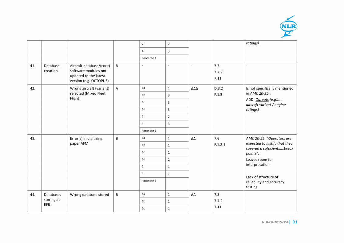
NLR-CR-2015-354 | 91
2 2
ratings)
4 3
Footnote 1
41. Database creation
Aircraft database/(core) software modules not updated to the latest version (e.g. OCTOPUS)
B - - - 7.3 7.7.2 7.11
-
42. Wrong aircraft (variant) selected (Mixed Fleet Flight)
A 1a 1 ∆∆∆
D.3.2 F.1.3
Is not specifically mentioned in AMC 20-25:. ADD: Outputs (e.g…… aircraft variant / engine ratings)
1b 3
1c 3
1d 3
2 2
4 3
Footnote 1
43. Error(s) in digitizing paper AFM
B 1a 1 ∆∆
7.6 F.1.2.1
AMC 20-25: “Operators are expected to justify that they covered a sufficient……break points”. Leaves room for interpretation Lack of structure of reliability and accuracy testing.
1b 1
1c 1
1d 2
2 1
4 1
Footnote 1
44. Databases storing at EFB
Wrong database stored B 1a 1 ∆∆ 7.3 7.7.2 7.11
1b 1
1c 1

Best practices for approval of Performance and MB applications on EFBs
92 | NLR-CR-2015-354
1d 2
2 1
4 1
Footnote 1
45. Not storing database when required (i.e. not keeping database up-to-date)
B - - - 7.3 7.7.2 7.11
46. Database storing errors at bit-level
B 1a 1 ∆∆
7.6 F.1.2.1
AMC 20-25: Operators are expected to justify that they covered a sufficient……break point”. Leaves room for interpretation Lack of structure of reliability and accuracy testing.
1b 1
1c 1
1d 2
2 1
4 1
Footnote 1
47. Introducing viruses B 1a 1 ∆∆
7.9 This requires expert knowledge on information technology which might be not available at NAA level.
1b 1
1c 1
1d 2
2 1
4 1
Footnote 1
48. Security: corruption of database/software
B 1a 1 ∆∆
7.9 This requires expert knowledge on information 1b 1

NLR-CR-2015-354 | 93
1c 1
technology which might be not available at NAA level.
1d 2
2 1
4 1
Footnote 1
49. Software management errors (OS update). Tool not available.
B - - - 7.3 7.11
50. Network problems (gatelink)
B - - - None Not specified in AMC 20-25
51. Database updating during flight (future)
B - - - None Not specified in AMC 20-25
52. Software design (calculation module)
Inaccuracy/errors of (large) deviations from certified or advisory data
B 1a 1 ∆∆
F AMC 20-25: Lack of structure of reliability and accuracy testing
1b 1
1c 1
1d 2
2 1
4 1
Footnote 1
53. Inaccurate paper source B - - - Outside scope AMC 20-25
54. Wrong output due to settings (e.g. balance arms for fuel tanks, cg. envelope)
B 1a 1 ∆∆
7.3 7.11.1 7.14 F.1.2.1
AMC 20-25: Lack of structure of reliability and accuracy testing.
1b 1
1c 1
1d 2
2 1

Best practices for approval of Performance and MB applications on EFBs
94 | NLR-CR-2015-354
4 1
Footnote 1
55. Wrong output due to errors in software
B 1a 1 ∆∆
F AMC 20-25: Lack of structure of reliability and accuracy testing
1b 1
1c 1
1d 2
2 1
4 1
Footnote 1
56. Wrong output due to changes as result of user interference (e.g. unauthorized access)
B 1a 1 ∆∆
7.9 F.1.1
AMC 20-25: Not clear how integrity should be checked. 1b 1
1c 1
1d 2
2 1
4 1
Footnote 1
57. Wrong output due to (internal/external) unit conversion errors
A 1a 1 ∆∆∆
F AMC 20-25: Lack of structure of reliability and accuracy testing.
1b 3
1c 3
1d 3
2 2
4 3
Footnote 1
58. Wrong output due to A 1a 1 ∆∆∆ None The interference from

NLR-CR-2015-354 | 95
interference from multiple applications (e.g. double startup of applications) Wrong output chosen from multiple calculations
1b 3
multiple applications should be checked.
1c 3
1d 3
2 2
4 3
Footnote 1
59. Wrong output due to interface problems between software from manufacturer and operator (i.e. between different shells/layers of software)
B 1a 1 ∆∆
7.6 F.1
AMC 20-25: “Operators are expected to justify that they covered a sufficient……break points”. Leaves room for interpretation
1b 1
1c 1
1d 2
2 1
4 1
Footnote 1
60. Insufficient output responsiveness
B - - - F.1.2. D.2.6.
61. Input HMI by pilots
Typos A 1a 1 ∆∆∆
D.3.2. F.1.3.
AMC 20-25: Outputs: the requirement to display the input data at the output data screen to allow cross checking of correct input data after the calculation. F.1.3 (a): it is not clear what “independently” means (e.g. 2 pilots making use of multiple efb’s or 2 pilots making separate calculation
1b 3
1c 3
1d 3
2 2
4 3
Footnote 1

Best practices for approval of Performance and MB applications on EFBs
96 | NLR-CR-2015-354
using the same efb)
62. Wrong data from source (e.g. passenger or loading reporting)
B 1a 1 ∆∆
- Outside AMC 20-25 1b 1
1c 1
1d 2
2 1
4 1
Footnote 1
63. Finger trouble A 1a 1 ∆∆∆
D.3.2. F.1.3.
AMC 20-25: Outputs: the requirement to display the input data at the output data screen to allow cross checking of correct input data after the calculation. F.1.3 (a): it is not clear what “independently” means (e.g. 2 pilots making use of multiple efb’s or 2 pilots making separate calculation using the same efb)
1b 3
1c 3
1d 3
2 2
4 3
Footnote 1
64. Calculations Data from previous flight used
A 1a 1 ∆∆∆
D.3.2. (modifications)
AMC 20-25: Outputs: the requirement to display the input data at the output data screen to allow cross checking of correct input data after the calculation.
1b 3
1c 3
1d 3
2 2
4 3
Footnote 1

NLR-CR-2015-354 | 97
65. Previous data not flushed
B 1a 1 ∆∆
D.3.2. (modifications)
AMC 20-25: Outputs: the requirement to display the input data at the output data screen to allow cross checking of correct input data after the calculation.
1b 1
1c 1
1d 2
2 1
4 1
Footnote 1
66. Output HMI to pilots
Errors due to different layout (EFB output vs. FMC input)
A 1a 1 ∆∆∆
D.2.4.1.2 1b 3
1c 3
1d 3
2 2
4 3
Footnote 1
67. Errors in unit conversions
A 1a 1 ∆∆∆
7.6 F.1
AMC 20-25: “Operators are expected to justify that they covered a sufficient……break points”. Leaves room for interpretation
1b 3
1c 3
1d 3
2 2
4 3
Footnote 1
TALP/MB
68. Interface errors between TALP & MB
B 1a 1 ∆∆
6.1.2.2 F1.2.1
This interface is not specifically mentioned in 1b 1
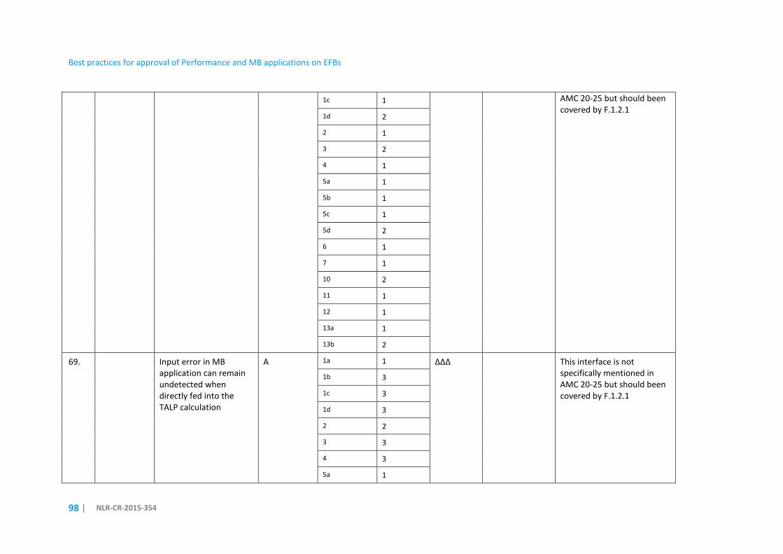
Best practices for approval of Performance and MB applications on EFBs
98 | NLR-CR-2015-354
1c 1
AMC 20-25 but should been covered by F.1.2.1
1d 2
2 1
3 2
4 1
5a 1
5b 1
5c 1
5d 2
6 1
7 1
10 2
11 1
12 1
13a 1
13b 2
69. Input error in MB application can remain undetected when directly fed into the TALP calculation
A 1a 1 ∆∆∆
This interface is not specifically mentioned in AMC 20-25 but should been covered by F.1.2.1
1b 3
1c 3
1d 3
2 2
3 3
4 3
5a 1

NLR-CR-2015-354 | 99
FOOT NOTES: 1) Effect 3,5a-d,6,7, 8, 10,11,12,13a-b, only if the mass and balance output is (directly) used as input for the performance tool 2) Effect 7,10,11,12, only if the mass and balance output is (directly) used as input for the performance tool.
5b 3
5c 3
5d 3
6 1
7 1
10 3
11 2
12 1
13a 2
13b 3

Best practices for approval of Performance and MB applications on EFBs
100 | NLR-CR-2015-354
This page is intentionally left blank.

W H A T I S N L R ?
The NL R i s a D utc h o rg an i s at io n th at i de n t i f i es , d ev e lop s a n d a p pl i es h i gh -t ech know l ed g e i n t he
aero s pac e sec tor . Th e NLR ’s ac t i v i t i es ar e soc ia l ly r e lev an t , m ar ke t-or i en ta te d , an d co n d uct ed
no t- for - p ro f i t . I n t h i s , th e NL R s erv e s to bo ls te r th e gove r nm en t ’s i n nova t iv e c apa b i l i t ie s , w h i l e
a lso p romot i ng t he i n nova t iv e a n d com p et i t iv e ca pa c i t ie s o f i t s p ar tn er com pa ni e s .
The NLR, renowned for i ts leading expert ise, professional approach and independent consultancy, is
staffed by c l ient-orientated personnel who are not only highly ski l led and educated, but a lso
continuously strive to develop and improve their competencies. The NLR moreover possesses an
impressive array of high qual ity research fac i l i t ies.
NLR – Dedicated to innovation in aerospace

Related Documents