EET 450 – Advanced Digital Video Display Systems

EET 450 – Advanced Digital Video Display Systems.
Dec 21, 2015
Welcome message from author
This document is posted to help you gain knowledge. Please leave a comment to let me know what you think about it! Share it to your friends and learn new things together.
Transcript
EET 450 – Advanced Digital
Video Display Systems

Video Display - CRT
Video displays convert the digital information stored in memory to some form of visible displayOriginally, the Cathode Ray Tube was used
Electrons were ‘boiled’ off of a plate, then accelerated to strike a plate covered in an phosphorThe phosphor glows due to the energy of the electron
CRT
By controlling the position on the screen, and the intensity of the dot, intelligible information can be displayed.
The CRT is a glass encapsulated array of electrodes
Contained in a vacuum
RASTOR display versus VECTOR display

CRT

CRT
The Electron gun is the cathode part of the display
Electrons are boiled off a beryllium plateThe electrons are accelerated by an electric potential with plates in the neck
The cloud of electrons is shaped into a beam
The electrons in the beam are accelerated by the attraction to the face (anode) of the CRT

CRT
As the electron beam passes through the funnel on the way to the face, it is deflected
A raster display, sweeps from left to right/ top to bottom of the displayAs the face is ‘painted’ by the electron beam, the intensity of the beam is varied by control plates in the neck.
At the face, the phosphor is struck by the electron beam

CRT
The color of the spot of phosphor depends on which rare earth element is used in the phosphor
Monochrome CRT’s use a single phosphor
Color CRT’s use 3 primary colors of phosphors to obtain the RED, GREEN and BLUE
The additive color blending scheme allows any color to be made from RGB combinations

CRT FaceThe phosphor is applied to the face in a variety of patterns.
aperture shadow slot grill mask mask
CRT Face
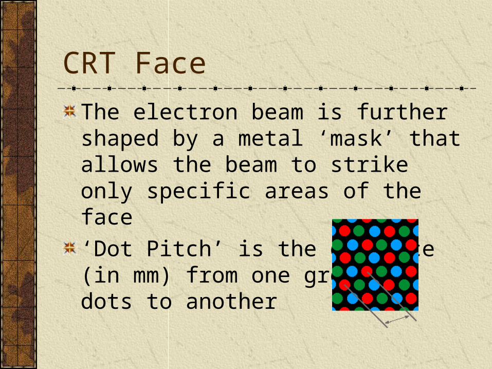
The electron beam is further shaped by a metal ‘mask’ that allows the beam to strike only specific areas of the face
‘Dot Pitch’ is the distance (in mm) from one group of dots to another
CRT Characteristics
The shape of the face has much to do with distortions
Screen curvature
ResolutionVertical versus horizontal dots
Anti-glare treatmentScreen sizeAspect Ratio
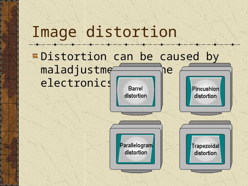
Image distortion
Distortion can be caused by maladjustment of the electronics
Image distortion
The beam must be adjusted to correctly strike the groups of phosphors which make up a pixel
Purity
Linearity adjustment
Display Characteristics
InterlacingEach sweep of the face paints alternately even/odd lines
• Keeps the required bandwidth down
Non-interlaced displays are standard nowEach line is painted, every sweep
See table 17.3 for bandwidths of standard video displays
Display characteristics
The vertical sweep is dependent on ‘sync’ frequency
Most monitors are now ‘multi-sync’ or multi frequency
TV’s are at a rate of 30 frames per second
CRTs for computers range from 30 to 80+ per second.

Other features
Energy StarLow power requirements
Sleep mode
Monitor off (see the discussion from ‘power supply lecture on ‘green’ requirements.)
Plug and PlayCRT’s now comply with PNP standard

Flat Panel Systems
LCD – Nematic technologySupertwist, double supertwist, etc.
Light is passed through a ‘liquid crystal’• Polarization of light
• Dependent on electrical field
• Passing light through a static polarizing filter, then through ‘spot’ of varying polarization, gives light/dark

LCD’s

LCD’s
‘Spots’ of screen are passed through colored filters to provide RGB components
The eye blends spots into single colors.
Alternative to Nematic technology LCD’s is Cholesteric Technology
Bi-stable – thus more energy efficient.

LCD’s
Passive matrixControl voltages are applied at edges of LCD panel
Heat dissipation and contrast are a problem
Active MatrixTransistors are embedded in the display panel.
Power is applied to transistor, which amplifies contrast.

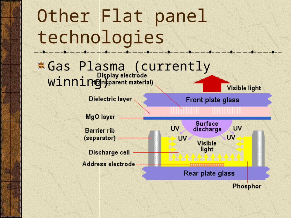
Other Flat panel technologies
DSTN

Other Flat panel technologies
Field Emission display

Other Flat panel technologies
Electro-Luminescent display – LED
Other Flat panel technologies
Gas Plasma (currently winning)
Other Flat panel technologies
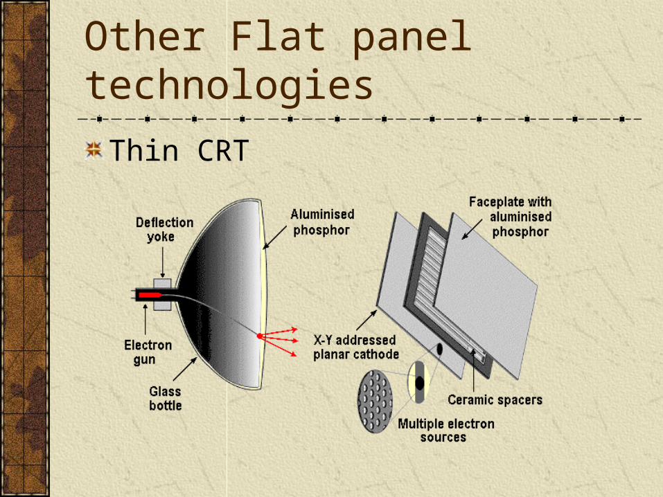
Thin CRT

Other Display Units
Projection units
Overhead display panels
VR Goggles
3D glasses

Connectors
CRT connectors are now standard at 15 pin high-density D-shell connector
Replaces 9 pin D connector
Other physical connections
BNC
Enhanced Video Connector
Related Documents