EET 2233 COURSE OVERVIEW

Welcome message from author
This document is posted to help you gain knowledge. Please leave a comment to let me know what you think about it! Share it to your friends and learn new things together.
Transcript

EET 2233
COURSE OVERVIEW
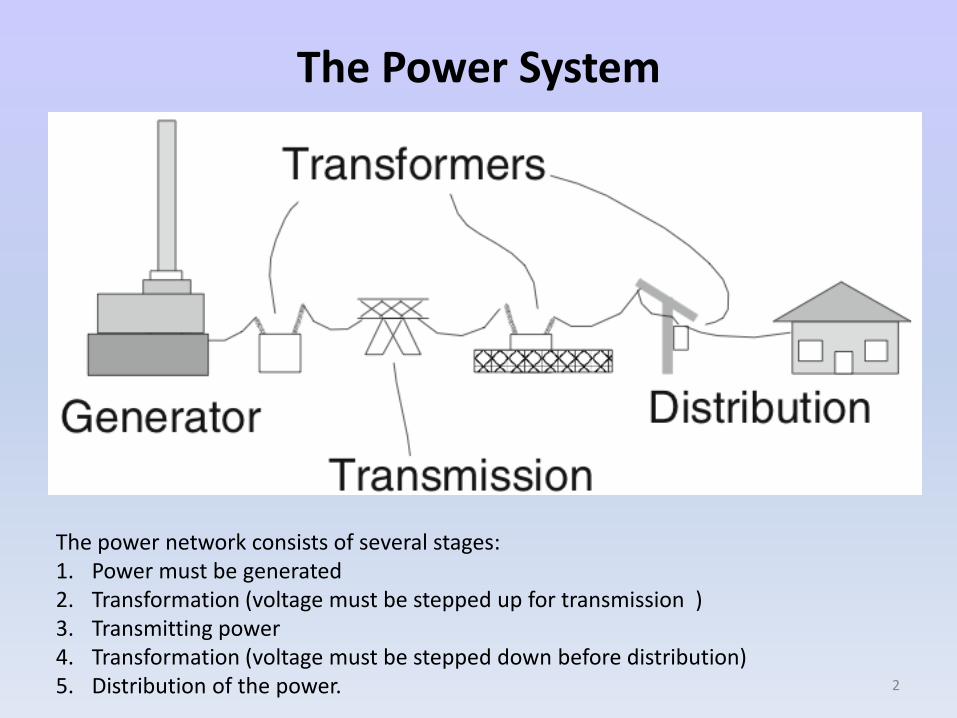
The Power System
The power network consists of several stages:1. Power must be generated 2. Transformation (voltage must be stepped up for transmission )3. Transmitting power4. Transformation (voltage must be stepped down before distribution)5. Distribution of the power. 2
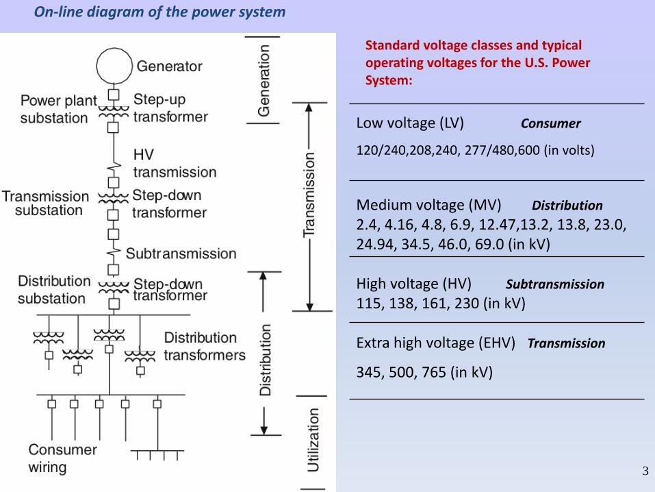
On-line diagram of the power system
Standard voltage classes and typical operating voltages for the U.S. Power System:
Low voltage (LV) Consumer
120/240,208,240, 277/480,600 (in volts)
Medium voltage (MV) Distribution
2.4, 4.16, 4.8, 6.9, 12.47,13.2, 13.8, 23.0, 24.94, 34.5, 46.0, 69.0 (in kV)
High voltage (HV) Subtransmission
115, 138, 161, 230 (in kV)
Extra high voltage (EHV) Transmission
345, 500, 765 (in kV)
3
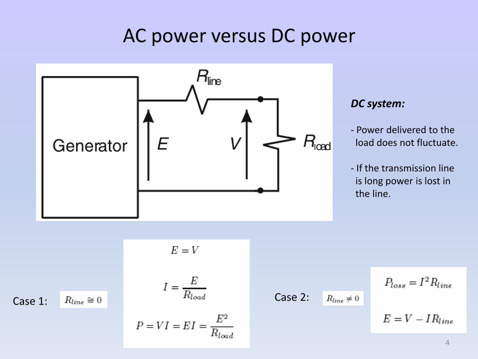
AC power versus DC power
Case 1: Case 2:
DC system:
- Power delivered to theload does not fluctuate.
- If the transmission lineis long power is lost in the line.
4
AC system:
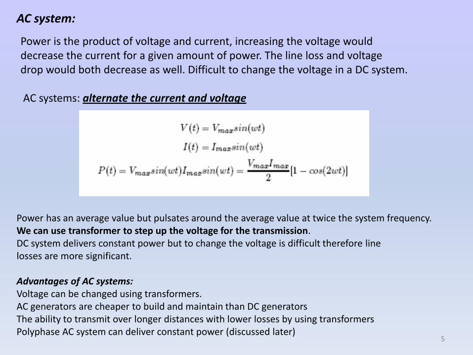
Power is the product of voltage and current, increasing the voltage woulddecrease the current for a given amount of power. The line loss and voltagedrop would both decrease as well. Difficult to change the voltage in a DC system.
AC systems: alternate the current and voltage
Power has an average value but pulsates around the average value at twice the system frequency. We can use transformer to step up the voltage for the transmission. DC system delivers constant power but to change the voltage is difficult therefore linelosses are more significant.
Advantages of AC systems:Voltage can be changed using transformers.AC generators are cheaper to build and maintain than DC generatorsThe ability to transmit over longer distances with lower losses by using transformersPolyphase AC system can deliver constant power (discussed later)
5
Phasors
Convenient way to represent voltages and currents using phasor form (work in phasor domain)
In its simplest form, a phasor can be thought as a complex number that has magnitude and phase of a sinusoidal function and can be represented partially as a vector in the complex plane.
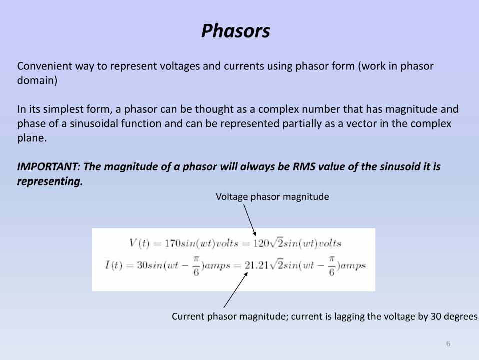
IMPORTANT: The magnitude of a phasor will always be RMS value of the sinusoid it is representing.
Voltage phasor magnitude
Current phasor magnitude; current is lagging the voltage by 30 degrees
6
Impedance in AC Circuits
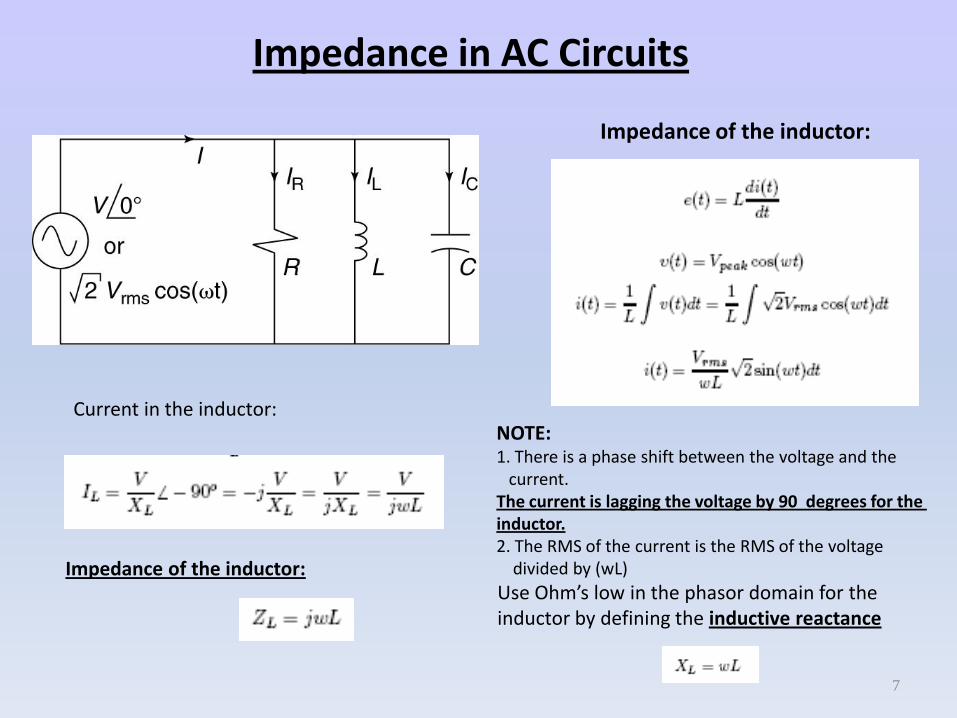
Impedance of the inductor:
NOTE: 1. There is a phase shift between the voltage and the
current. The current is lagging the voltage by 90 degrees for the inductor.2. The RMS of the current is the RMS of the voltage
divided by (wL)
Use Ohm’s low in the phasor domain for the inductor by defining the inductive reactance
Current in the inductor:
Impedance of the inductor:
7
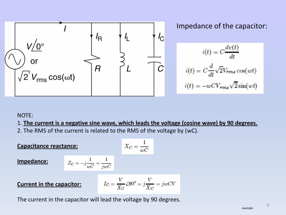
Impedance of the capacitor:
NOTE: 1. The current is a negative sine wave, which leads the voltage (cosine wave) by 90 degrees.2. The RMS of the current is related to the RMS of the voltage by (wC).
Capacitance reactance:
Impedance:
Current in the capacitor:
The current in the capacitor will lead the voltage by 90 degrees.example
8
Power in Single-Phase AC Circuits
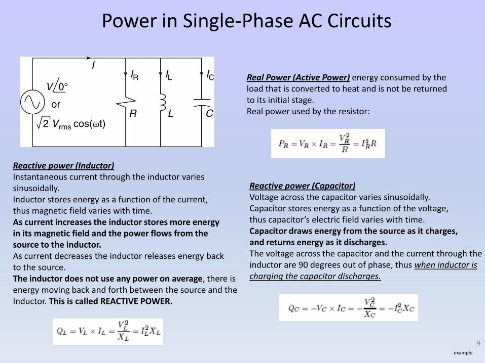
Real Power (Active Power) energy consumed by the load that is converted to heat and is not be returnedto its initial stage.Real power used by the resistor:
Reactive power (Inductor)Instantaneous current through the inductor variessinusoidally.Inductor stores energy as a function of the current, thus magnetic field varies with time.As current increases the inductor stores more energyin its magnetic field and the power flows from the source to the inductor.As current decreases the inductor releases energy backto the source.The inductor does not use any power on average, there is energy moving back and forth between the source and the Inductor. This is called REACTIVE POWER.
Reactive power (Capacitor)Voltage across the capacitor varies sinusoidally.Capacitor stores energy as a function of the voltage, thus capacitor’s electric field varies with time.Capacitor draws energy from the source as it charges, and returns energy as it discharges.The voltage across the capacitor and the current through the inductor are 90 degrees out of phase, thus when inductor ischarging the capacitor discharges.
9example
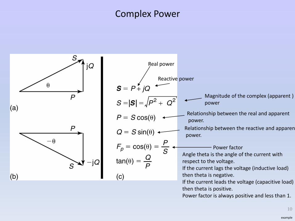
Complex Power
Real power
Reactive power
Magnitude of the complex (apparent )power
Relationship between the real and apparentpower.
Power factorAngle theta is the angle of the current with respect to the voltage.If the current lags the voltage (inductive load)then theta is negative.If the current leads the voltage (capacitive load)then theta is positive.Power factor is always positive and less than 1.
Relationship between the reactive and apparentpower.
10
example
Three-Phase WYE Configuration
11
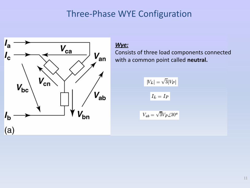
Wye: Consists of three load components connected with a common point called neutral.
Three-Phase DELTA Configuration
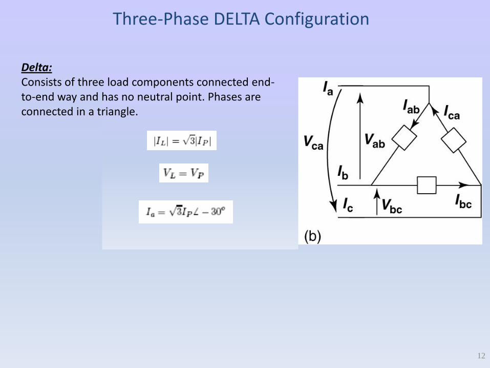
Delta:Consists of three load components connected end-to-end way and has no neutral point. Phases are connected in a triangle.
12
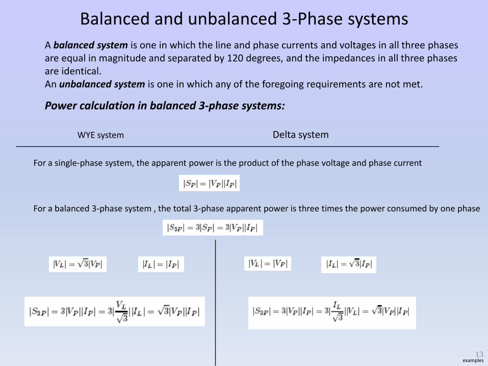
Balanced and unbalanced 3-Phase systems
A balanced system is one in which the line and phase currents and voltages in all three phasesare equal in magnitude and separated by 120 degrees, and the impedances in all three phasesare identical.An unbalanced system is one in which any of the foregoing requirements are not met.
Power calculation in balanced 3-phase systems:
WYE system Delta system
For a single-phase system, the apparent power is the product of the phase voltage and phase current
For a balanced 3-phase system , the total 3-phase apparent power is three times the power consumed by one phase
13examples
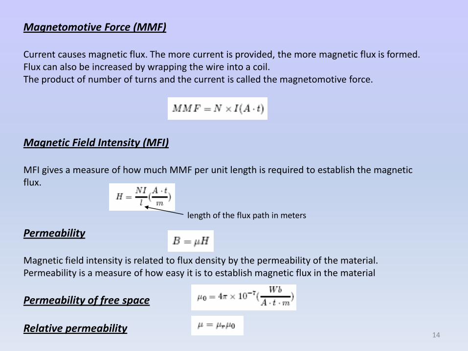
Magnetomotive Force (MMF)
Current causes magnetic flux. The more current is provided, the more magnetic flux is formed.Flux can also be increased by wrapping the wire into a coil.The product of number of turns and the current is called the magnetomotive force.
Magnetic Field Intensity (MFI)
MFI gives a measure of how much MMF per unit length is required to establish the magnetic flux.
Permeability
Magnetic field intensity is related to flux density by the permeability of the material.Permeability is a measure of how easy it is to establish magnetic flux in the material
Permeability of free space
Relative permeability
length of the flux path in meters
14
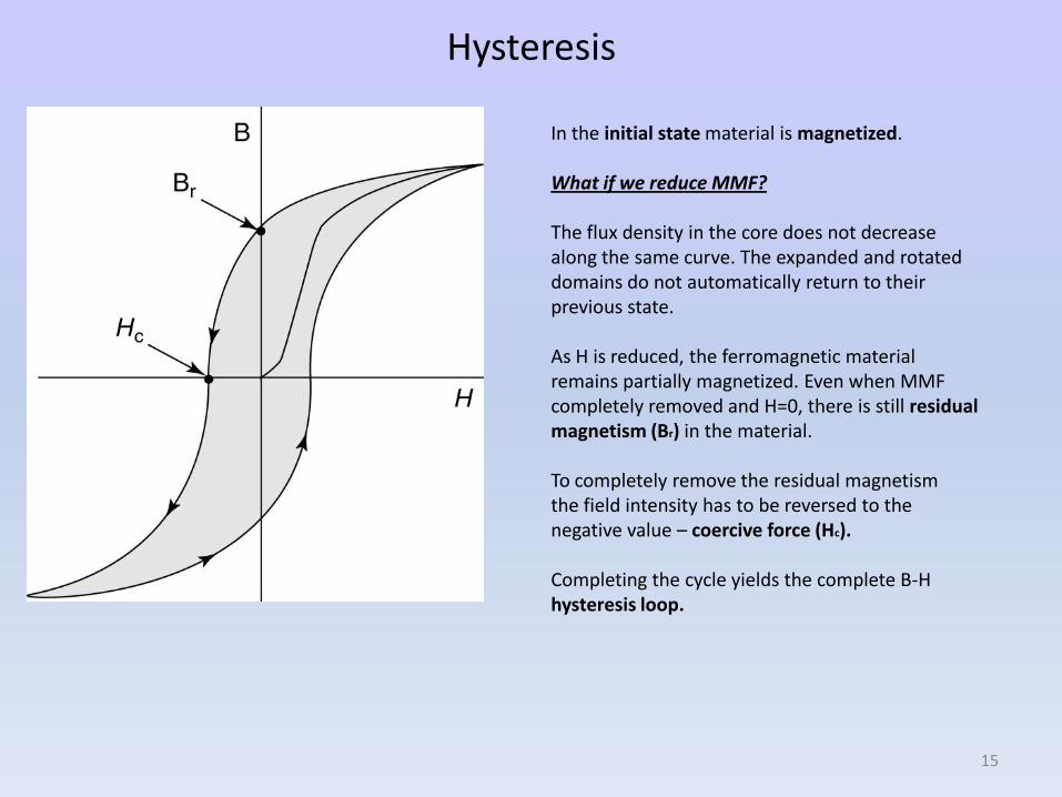
Hysteresis
In the initial state material is magnetized.
What if we reduce MMF?
The flux density in the core does not decrease along the same curve. The expanded and rotateddomains do not automatically return to theirprevious state.
As H is reduced, the ferromagnetic material remains partially magnetized. Even when MMF completely removed and H=0, there is still residualmagnetism (Br) in the material.
To completely remove the residual magnetismthe field intensity has to be reversed to the negative value – coercive force (Hc).
Completing the cycle yields the complete B-H hysteresis loop.
15
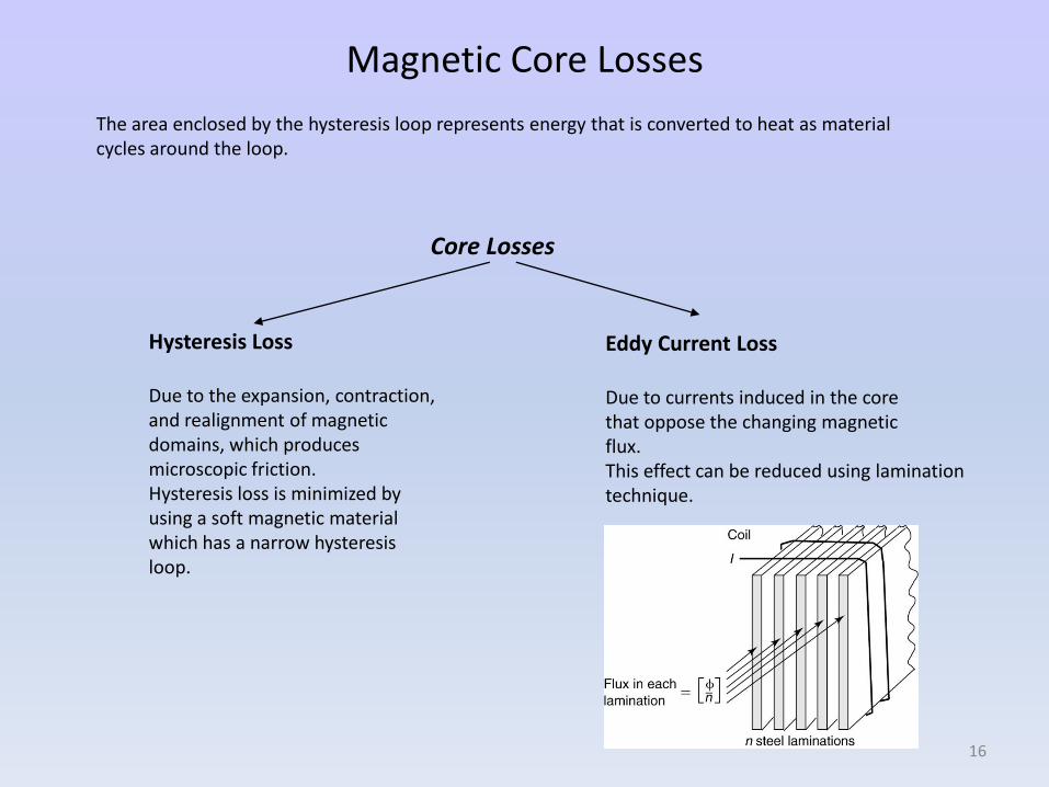
Magnetic Core Losses
The area enclosed by the hysteresis loop represents energy that is converted to heat as material cycles around the loop.
Core Losses
Hysteresis Loss
Due to the expansion, contraction, and realignment of magnetic domains, which produces microscopic friction. Hysteresis loss is minimized byusing a soft magnetic material which has a narrow hysteresis loop.
Eddy Current Loss
Due to currents induced in the corethat oppose the changing magnetic flux. This effect can be reduced using lamination technique.
16
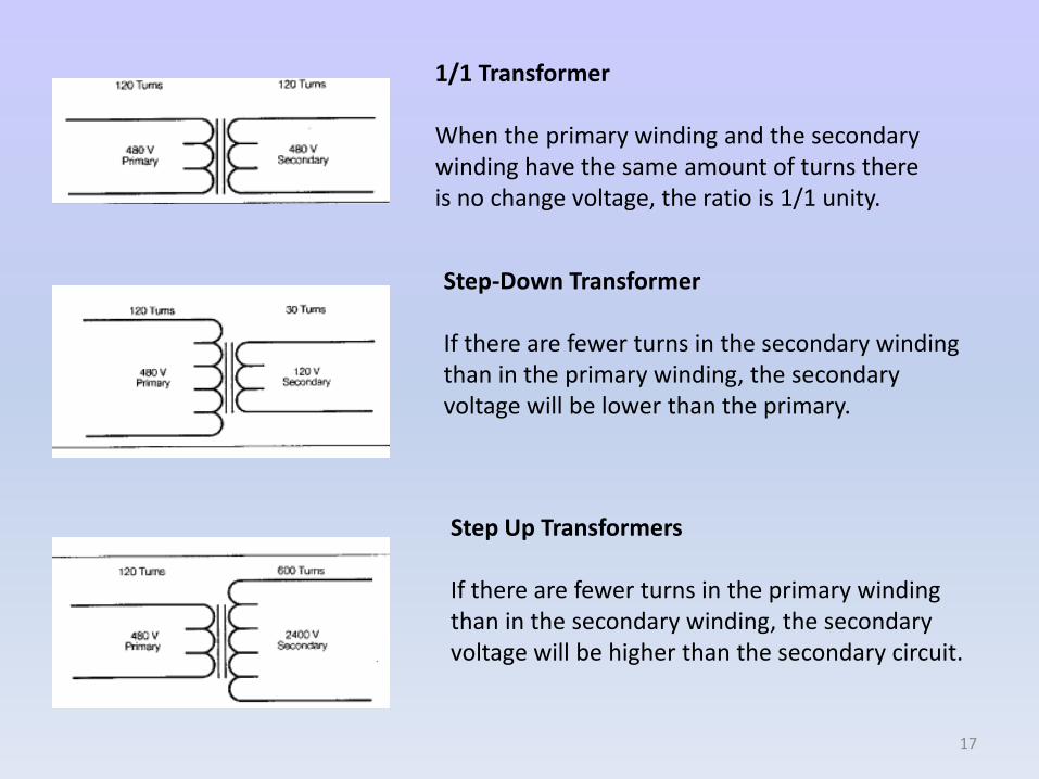
1/1 Transformer
When the primary winding and the secondary winding have the same amount of turns there is no change voltage, the ratio is 1/1 unity.
Step-Down Transformer
If there are fewer turns in the secondary winding than in the primary winding, the secondary voltage will be lower than the primary.
Step Up Transformers
If there are fewer turns in the primary winding than in the secondary winding, the secondary voltage will be higher than the secondary circuit.
17
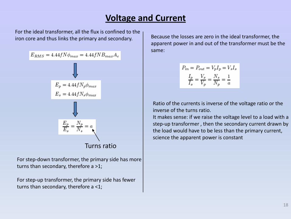
Voltage and Current
For the ideal transformer, all the flux is confined to theiron core and thus links the primary and secondary.
Turns ratio
For step-down transformer, the primary side has moreturns than secondary, therefore a >1;
For step-up transformer, the primary side has fewerturns than secondary, therefore a <1;
Because the losses are zero in the ideal transformer, the apparent power in and out of the transformer must be the same:
Ratio of the currents is inverse of the voltage ratio or the inverse of the turns ratio.It makes sense: if we raise the voltage level to a load with a step-up transformer , then the secondary current drawn by the load would have to be less than the primary current, science the apparent power is constant
18
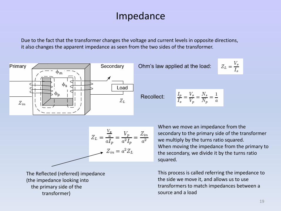
Impedance
Due to the fact that the transformer changes the voltage and current levels in opposite directions, it also changes the apparent impedance as seen from the two sides of the transformer.
Ohm’s law applied at the load:
Recollect:
The Reflected (referred) impedance(the impedance looking into
the primary side of the transformer)
When we move an impedance from the secondary to the primary side of the transformerwe multiply by the turns ratio squared.When moving the impedance from the primary to the secondary, we divide it by the turns ratio squared.
This process is called referring the impedance to the side we move it, and allows us to use transformers to match impedances between a source and a load
19
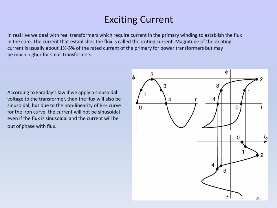
Exciting Current
In real live we deal with real transformers which require current in the primary winding to establish the flux in the core. The current that establishes the flux is called the exiting current. Magnitude of the exciting current is usually about 1%-5% of the rated current of the primary for power transformers but may be much higher for small transformers.
According to Faraday’s law if we apply a sinusoidal voltage to the transformer, then the flux will also be sinusoidal, but due to the non-linearity of B-H curve for the iron curve, the current will not be sinusoidal even if the flux is sinusoidal and the current will be
out of phase with flux.
20
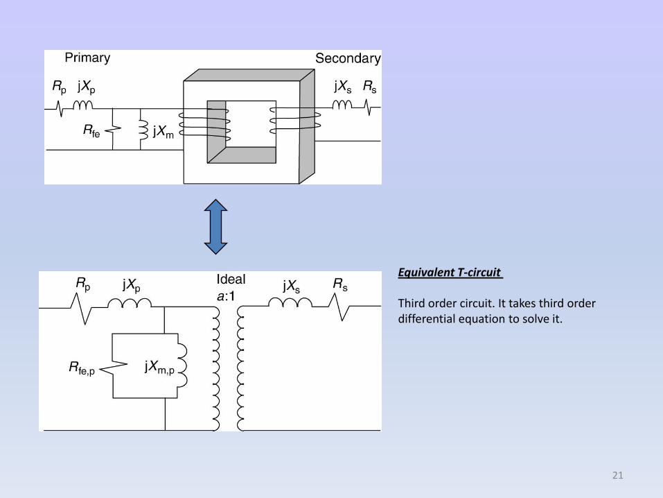
Equivalent T-circuit
Third order circuit. It takes third order differential equation to solve it.
21
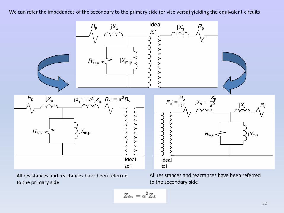
We can refer the impedances of the secondary to the primary side (or vise versa) yielding the equivalent circuits
All resistances and reactances have been referred to the primary side
All resistances and reactances have been referred to the secondary side
22
Series Equivalent Circuit
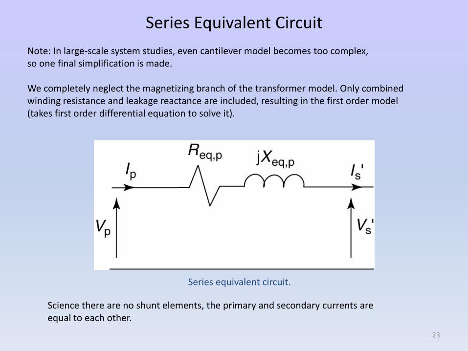
Note: In large-scale system studies, even cantilever model becomes too complex, so one final simplification is made.
We completely neglect the magnetizing branch of the transformer model. Only combined winding resistance and leakage reactance are included, resulting in the first order model (takes first order differential equation to solve it).
Series equivalent circuit.
Science there are no shunt elements, the primary and secondary currents are equal to each other.
23
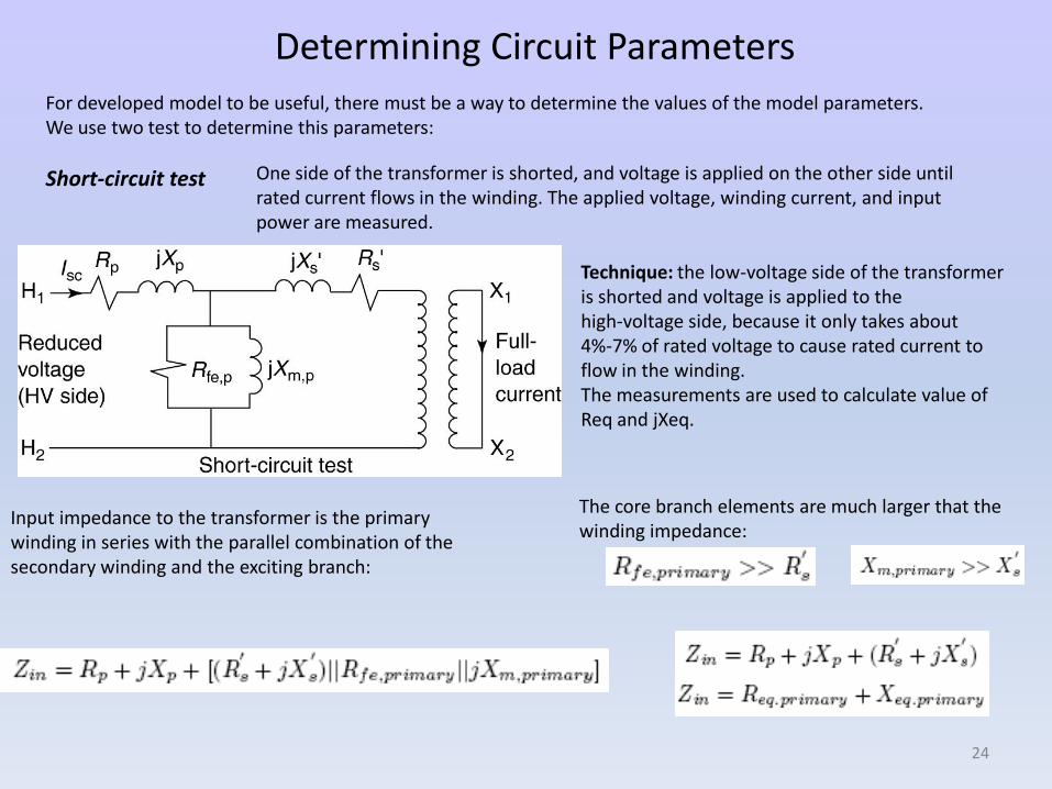
Determining Circuit ParametersFor developed model to be useful, there must be a way to determine the values of the model parameters.We use two test to determine this parameters:
Short-circuit test One side of the transformer is shorted, and voltage is applied on the other side until rated current flows in the winding. The applied voltage, winding current, and input power are measured.
Technique: the low-voltage side of the transformer is shorted and voltage is applied to the high-voltage side, because it only takes about 4%-7% of rated voltage to cause rated current to flow in the winding.The measurements are used to calculate value of Req and jXeq.
Input impedance to the transformer is the primary winding in series with the parallel combination of the secondary winding and the exciting branch:
The core branch elements are much larger that the winding impedance:
24
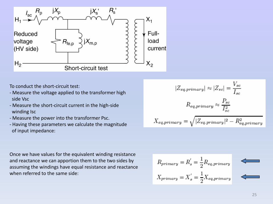
To conduct the short-circuit test: - Measure the voltage applied to the transformer high side Vsc
- Measure the short-circuit current in the high-side winding Isc
- Measure the power into the transformer Psc.- Having these parameters we calculate the magnitude of input impedance:
Once we have values for the equivalent winding resistance and reactance we can apportion them to the two sides by assuming the windings have equal resistance and reactance when referred to the same side:
25
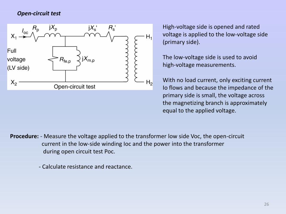
Open-circuit test
High-voltage side is opened and rated voltage is applied to the low-voltage side (primary side).
The low-voltage side is used to avoid high-voltage measurements.
With no load current, only exciting current Io flows and because the impedance of the primary side is small, the voltage across the magnetizing branch is approximately equal to the applied voltage.
Procedure: - Measure the voltage applied to the transformer low side Voc, the open-circuit current in the low-side winding Ioc and the power into the transformer during open circuit test Poc.
- Calculate resistance and reactance.
26
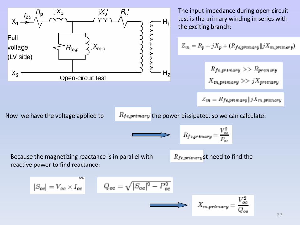
Now we have the voltage applied to and the power dissipated, so we can calculate:
Because the magnetizing reactance is in parallel with we first need to find the reactive power to find reactance:
The input impedance during open-circuit test is the primary winding in series with the exciting branch:
27
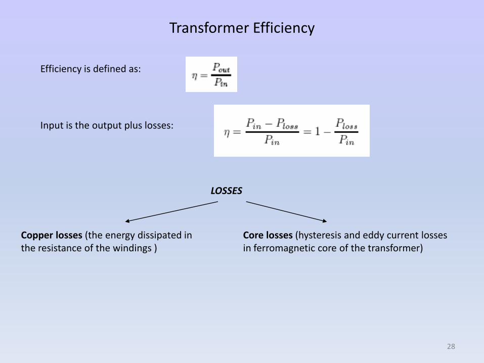
Transformer Efficiency
Efficiency is defined as:
Input is the output plus losses:
LOSSES
Copper losses (the energy dissipated in the resistance of the windings )
Core losses (hysteresis and eddy current losses in ferromagnetic core of the transformer)
28
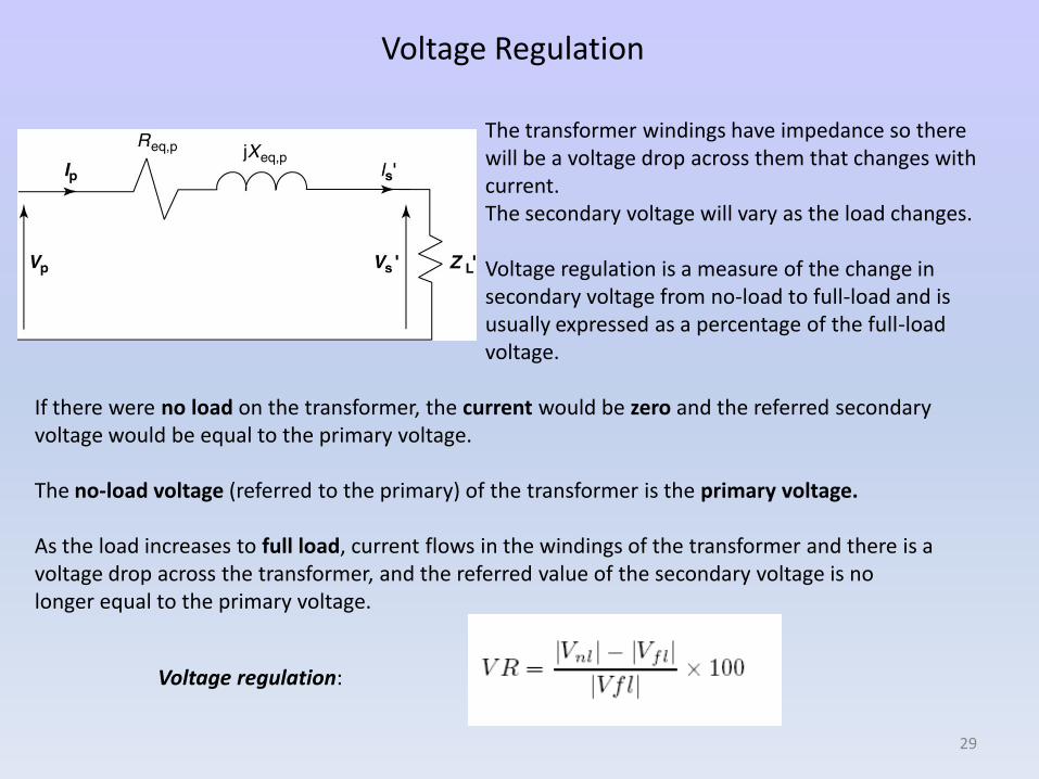
Voltage Regulation
The transformer windings have impedance so there will be a voltage drop across them that changes with current. The secondary voltage will vary as the load changes.
Voltage regulation is a measure of the change in secondary voltage from no-load to full-load and is usually expressed as a percentage of the full-load voltage.
If there were no load on the transformer, the current would be zero and the referred secondary voltage would be equal to the primary voltage.
The no-load voltage (referred to the primary) of the transformer is the primary voltage.
As the load increases to full load, current flows in the windings of the transformer and there is a voltage drop across the transformer, and the referred value of the secondary voltage is no longer equal to the primary voltage.
Voltage regulation:
29
Three-phase transformer connections
There are four major three-phase transformer connections :
1. WYE-WYE2. Delta-Delta3. WYE-Delta4. Delta-WYE
Three-phase transformers are less expensive than 3-single-phase transformers because less total core material is needed for the three-phase transformer and the packaging cost is reduced.
Additionally they take up less space, are lighter, require less on site external wiring
for installation, and more efficient than three single-phase transformers.
Single phase transformer has one voltage ratio which agrees with the turns ratio.
For 3-phase transformer:
1. Bank Ratio = BR = the ratio of line-to-line voltages.2. Phase Ratio = PR = the ratio of the voltages in the coils of the transformer and thus
agrees with the turns ratio.
30
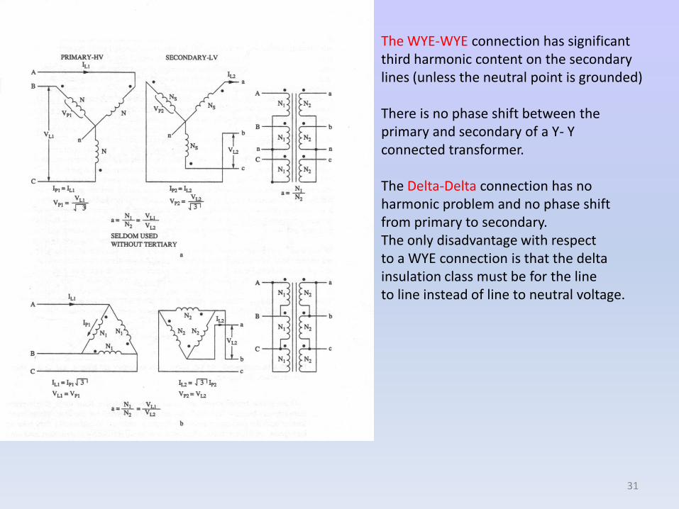
The WYE-WYE connection has significant third harmonic content on the secondary lines (unless the neutral point is grounded)
There is no phase shift between the primary and secondary of a Y- Y connected transformer.
The Delta-Delta connection has no harmonic problem and no phase shift from primary to secondary. The only disadvantage with respect to a WYE connection is that the delta insulation class must be for the line to line instead of line to neutral voltage.
31
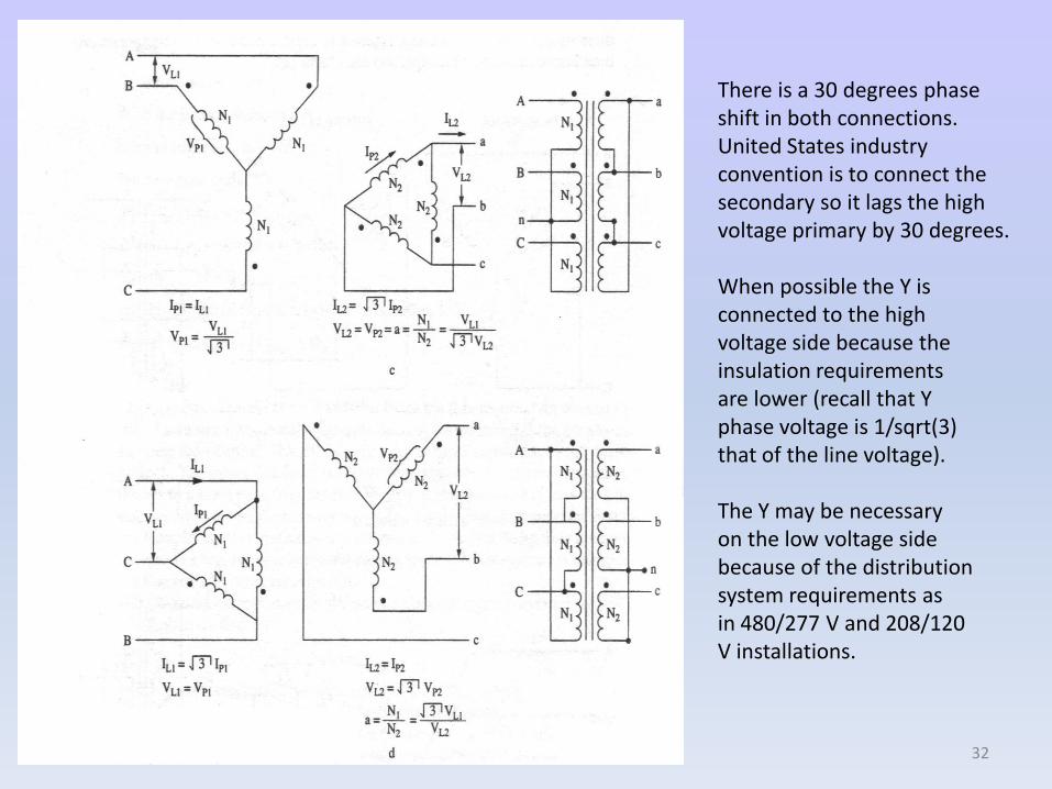
Figure 4.16 page 120
There is a 30 degrees phase shift in both connections. United States industry convention is to connect the secondary so it lags the high voltage primary by 30 degrees.
When possible the Y is connected to the high voltage side because the insulation requirements are lower (recall that Y phase voltage is 1/sqrt(3) that of the line voltage).
The Y may be necessary on the low voltage side because of the distribution system requirements as in 480/277 V and 208/120 V installations.
32
Motor:
An eclectic current interacts with a magnetic field to cause an electromagnetic torque, which drives some load. The load provides a mechanical torque, which opposes the electromagnetic torque.
Generator:
A mechanical torque is applied to turn conductors through a magnetic field and generate electric current. The mechanical torque is opposed by an electromagnetic torque that results fromthe interaction of the current with the magnetic field.
33
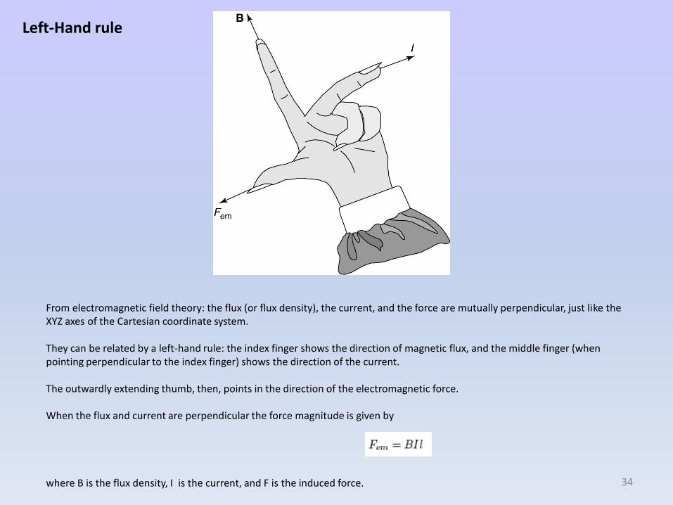
From electromagnetic field theory: the flux (or flux density), the current, and the force are mutually perpendicular, just like the XYZ axes of the Cartesian coordinate system.
They can be related by a left-hand rule: the index finger shows the direction of magnetic flux, and the middle finger (when pointing perpendicular to the index finger) shows the direction of the current.
The outwardly extending thumb, then, points in the direction of the electromagnetic force.
When the flux and current are perpendicular the force magnitude is given by
where B is the flux density, I is the current, and F is the induced force.
Left-Hand rule
34
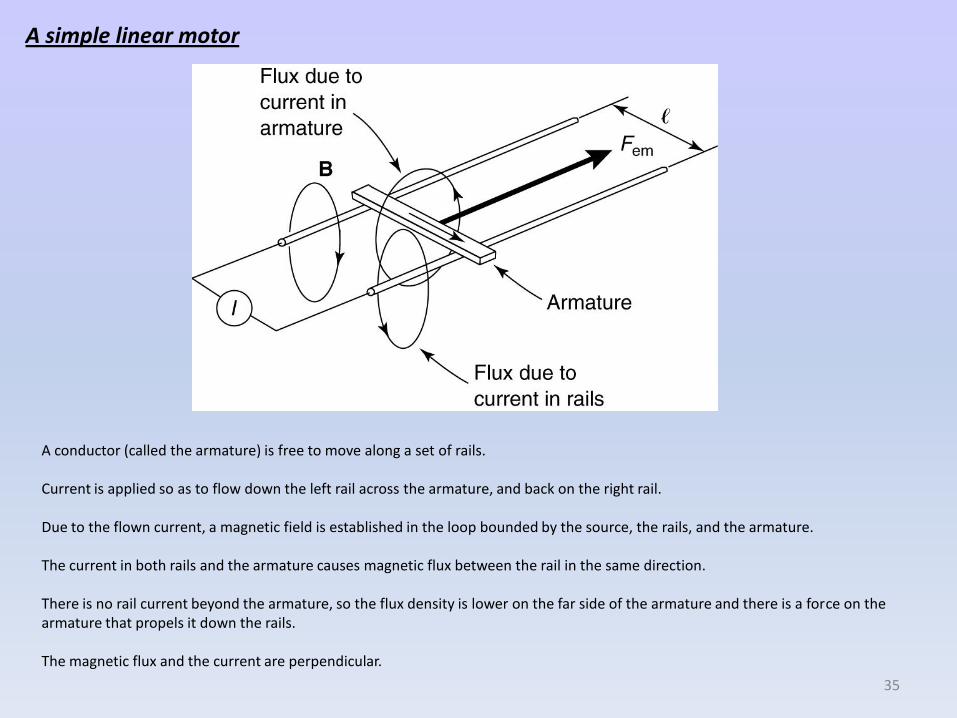
A conductor (called the armature) is free to move along a set of rails.
Current is applied so as to flow down the left rail across the armature, and back on the right rail.
Due to the flown current, a magnetic field is established in the loop bounded by the source, the rails, and the armature.
The current in both rails and the armature causes magnetic flux between the rail in the same direction.
There is no rail current beyond the armature, so the flux density is lower on the far side of the armature and there is a force on the armature that propels it down the rails.
The magnetic flux and the current are perpendicular.
A simple linear motor
35
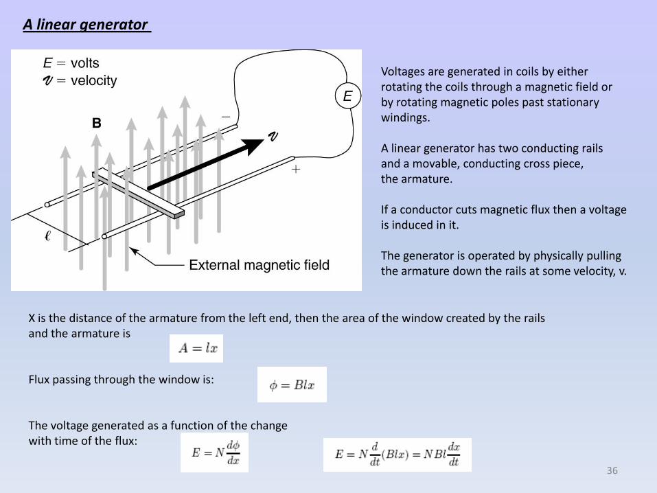
A linear generator
Voltages are generated in coils by either rotating the coils through a magnetic field or by rotating magnetic poles past stationary windings.
A linear generator has two conducting rails and a movable, conducting cross piece, the armature.
If a conductor cuts magnetic flux then a voltage is induced in it.
The generator is operated by physically pulling the armature down the rails at some velocity, v.
X is the distance of the armature from the left end, then the area of the window created by the rails and the armature is
Flux passing through the window is:
The voltage generated as a function of the changewith time of the flux:
36
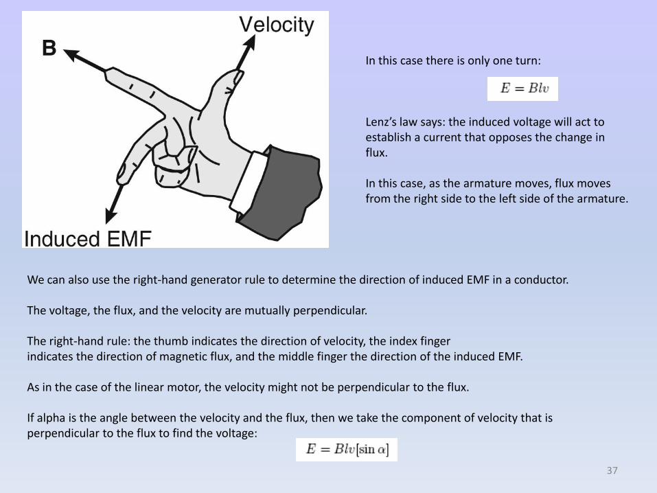
In this case there is only one turn:
Lenz’s law says: the induced voltage will act to establish a current that opposes the change in flux.
In this case, as the armature moves, flux movesfrom the right side to the left side of the armature.
We can also use the right-hand generator rule to determine the direction of induced EMF in a conductor.
The voltage, the flux, and the velocity are mutually perpendicular.
The right-hand rule: the thumb indicates the direction of velocity, the index finger indicates the direction of magnetic flux, and the middle finger the direction of the induced EMF.
As in the case of the linear motor, the velocity might not be perpendicular to the flux.
If alpha is the angle between the velocity and the flux, then we take the component of velocity that is perpendicular to the flux to find the voltage:
37
A simple AC machine
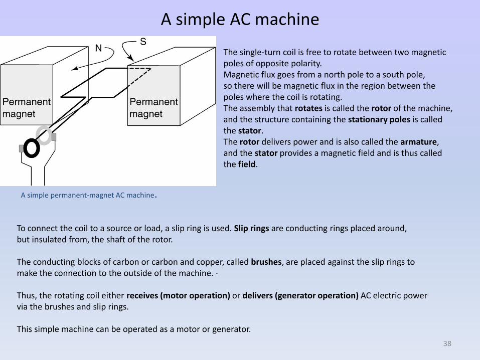
A simple permanent-magnet AC machine.
The single-turn coil is free to rotate between two magnetic poles of opposite polarity. Magnetic flux goes from a north pole to a south pole, so there will be magnetic flux in the region between the poles where the coil is rotating. The assembly that rotates is called the rotor of the machine,and the structure containing the stationary poles is called the stator. The rotor delivers power and is also called the armature, and the stator provides a magnetic field and is thus called the field.
To connect the coil to a source or load, a slip ring is used. Slip rings are conducting rings placed around, but insulated from, the shaft of the rotor.
The conducting blocks of carbon or carbon and copper, called brushes, are placed against the slip rings tomake the connection to the outside of the machine. ·
Thus, the rotating coil either receives (motor operation) or delivers (generator operation) AC electric power via the brushes and slip rings.
This simple machine can be operated as a motor or generator.
38
Motor Operation
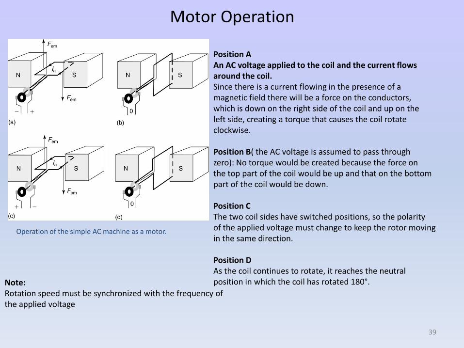
Operation of the simple AC machine as a motor.
Position AAn AC voltage applied to the coil and the current flows around the coil.Since there is a current flowing in the presence of a magnetic field there will be a force on the conductors,which is down on the right side of the coil and up on the left side, creating a torque that causes the coil rotate clockwise.
Position B( the AC voltage is assumed to pass through zero): No torque would be created because the force on the top part of the coil would be up and that on the bottom part of the coil would be down.
Position CThe two coil sides have switched positions, so the polarity of the applied voltage must change to keep the rotor movingin the same direction.
Position DAs the coil continues to rotate, it reaches the neutral position in which the coil has rotated 180°. Note:
Rotation speed must be synchronized with the frequency of the applied voltage
39
Generator Operation
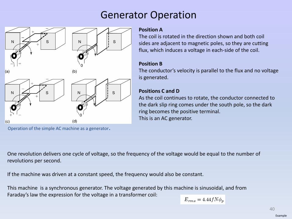
Operation of the simple AC machine as a generator.
Position AThe coil is rotated in the direction shown and both coil sides are adjacent to magnetic poles, so they are cutting flux, which induces a voltage in each-side of the coil.
Position BThe conductor’s velocity is parallel to the flux and no voltageis generated.
Positions C and DAs the coil continues to rotate, the conductor connected to the dark slip ring comes under the south pole, so the dark ring becomes the positive terminal. This is an AC generator.
One revolution delivers one cycle of voltage, so the frequency of the voltage would be equal to the number of revolutions per second.
If the machine was driven at a constant speed, the frequency would also be constant.
This machine is a synchronous generator. The voltage generated by this machine is sinusoidal, and from Faraday’s law the expression for the voltage in a transformer coil:
Example
40
A Simple DC Machine.
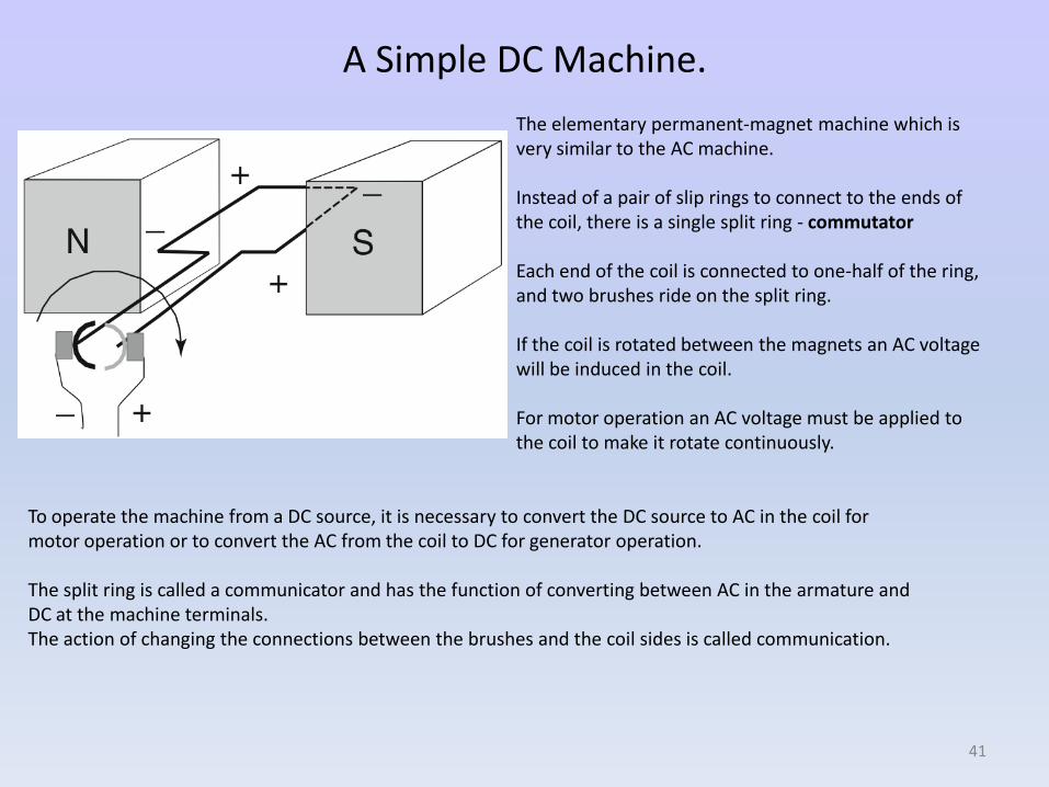
The elementary permanent-magnet machine which is very similar to the AC machine.
Instead of a pair of slip rings to connect to the ends of the coil, there is a single split ring - commutator
Each end of the coil is connected to one-half of the ring, and two brushes ride on the split ring.
If the coil is rotated between the magnets an AC voltage will be induced in the coil.
For motor operation an AC voltage must be applied to the coil to make it rotate continuously.
To operate the machine from a DC source, it is necessary to convert the DC source to AC in the coil for motor operation or to convert the AC from the coil to DC for generator operation.
The split ring is called a communicator and has the function of converting between AC in the armature and DC at the machine terminals. The action of changing the connections between the brushes and the coil sides is called communication.
41
Motor Operation
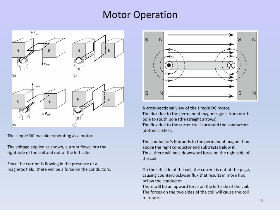
The simple DC machine operating as a motor.
The voltage applied as shown, current flows into the right side of the coil and out of the left side.
Since the current is flowing in the presence of a magnetic field, there will be a force on the conductors.
A cross-sectional view of the simple DC motor.The flux due to the permanent magnets goes from northpole to south pole (the straight arrows). The flux due to the current will surround the conductors(dotted circles).
The conductor’s flux adds to the permanent magnet fluxabove the right conductor and subtracts below it. Thus, there will be a downward force on the right side ofthe coil.
On the left side of the coil, the current is out of the page,causing counterclockwise flux that results in more flux below the conductor. There will be an upward force on the left side of the coil. The forces on the two sides of the coil will cause the coilto rotate.
42
Generator Operation
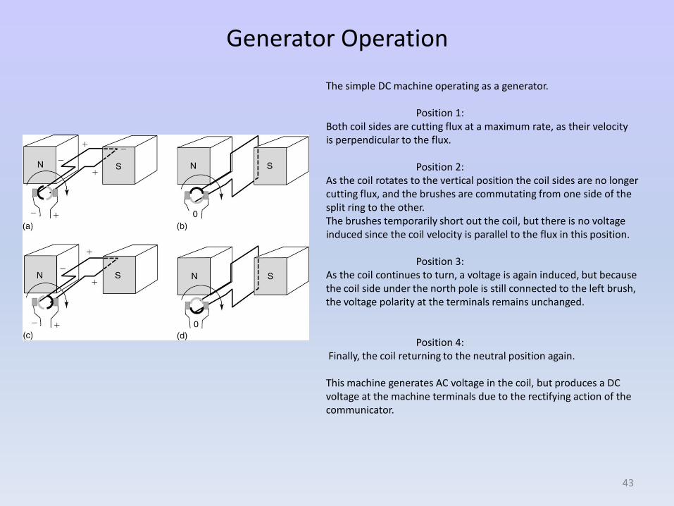
The simple DC machine operating as a generator.
Position 1:Both coil sides are cutting flux at a maximum rate, as their velocity is perpendicular to the flux.
Position 2:As the coil rotates to the vertical position the coil sides are no longercutting flux, and the brushes are commutating from one side of the split ring to the other. The brushes temporarily short out the coil, but there is no voltage induced since the coil velocity is parallel to the flux in this position.
Position 3:As the coil continues to turn, a voltage is again induced, but becausethe coil side under the north pole is still connected to the left brush, the voltage polarity at the terminals remains unchanged.
Position 4:Finally, the coil returning to the neutral position again.
This machine generates AC voltage in the coil, but produces a DC voltage at the machine terminals due to the rectifying action of the communicator.
43
Efficiency and Losses
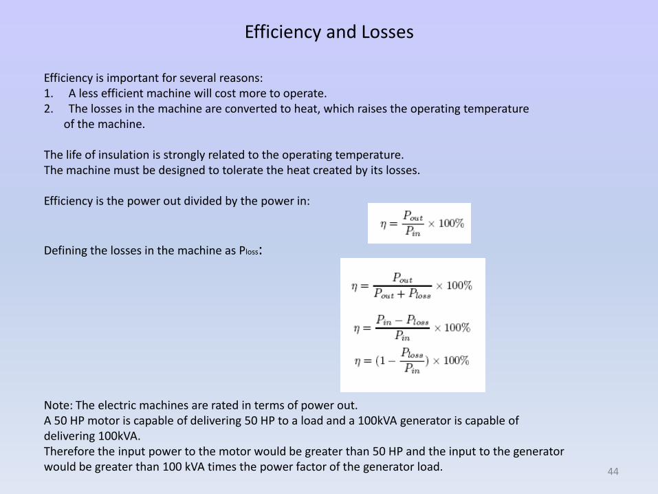
Efficiency is important for several reasons: 1. A less efficient machine will cost more to operate. 2. The losses in the machine are converted to heat, which raises the operating temperature
of the machine.
The life of insulation is strongly related to the operating temperature. The machine must be designed to tolerate the heat created by its losses.
Efficiency is the power out divided by the power in:
Defining the losses in the machine as Ploss:
Note: The electric machines are rated in terms of power out. A 50 HP motor is capable of delivering 50 HP to a load and a 100kVA generator is capable of delivering 100kVA.Therefore the input power to the motor would be greater than 50 HP and the input to the generator would be greater than 100 kVA times the power factor of the generator load. 44
Type of Losses
Copper Losses:Resistive losses in the winding of a machine are frequently referred to as copper losses. The resistance of a conductor varies with temperature and frequency.
Mechanical LossesThis category includes friction and windage losses. Friction occurs in the bearings that support the rotor shaft and between brushes and communicators or slip rings. Windage is basically the fluid friction due to the rotor and fan assembly.
Core LossesCore losses include the hysteresis and eddy current losses in the steel of the machine.
Stray LossesAny other losses and by convention, stray loss is taken to be I % of the output of DC machines.
45
In the DC machine, there are two types of field windings that are commonly used:
1) Shunt field: - Field windings are connected in parallel with the armature to the source voltage or
- Field windings are connected to a separate voltage source.
To keep the losses of the machine low and to reduce the power requirements for the source, shunt-field coils are constructed of a large number of turns of smaller-gauge wire.
2) Series-field Field winding are connected in series with the armature.
Series-field windings are constructed of a few turns of heavy-gauge wire and placed in series with the armature.
The types of field coils and the manner in which they are connected has a significant impact on the performance of the machine.
46
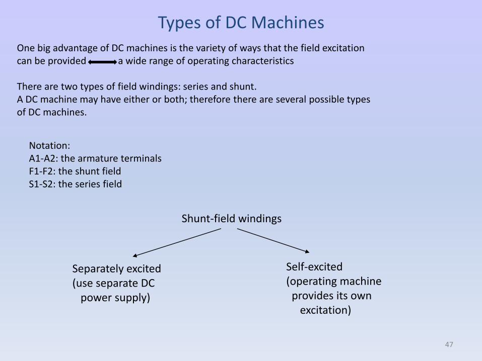
Types of DC MachinesOne big advantage of DC machines is the variety of ways that the field excitation can be provided a wide range of operating characteristics
There are two types of field windings: series and shunt. A DC machine may have either or both; therefore there are several possible types of DC machines.
Notation:A1-A2: the armature terminalsF1-F2: the shunt fieldS1-S2: the series field
Shunt-field windings
Separately excited(use separate DC
power supply)
Self-excited(operating machine
provides its own excitation)
47
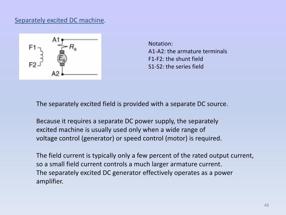
Separately excited DC machine.
The separately excited field is provided with a separate DC source.
Because it requires a separate DC power supply, the separately excited machine is usually used only when a wide range of voltage control (generator) or speed control (motor) is required.
The field current is typically only a few percent of the rated output current, so a small field current controls a much larger armature current. The separately excited DC generator effectively operates as a power amplifier.
Notation:A1-A2: the armature terminalsF1-F2: the shunt fieldS1-S2: the series field
48
Notation:A1-A2: the armature terminalsF1-F2: the shunt fieldS1-S2: the series field
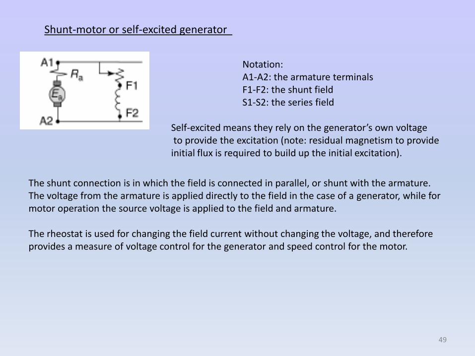
Self-excited means they rely on the generator’s own voltage to provide the excitation (note: residual magnetism to provide initial flux is required to build up the initial excitation).
Shunt-motor or self-excited generator
The shunt connection is in which the field is connected in parallel, or shunt with the armature.The voltage from the armature is applied directly to the field in the case of a generator, while for motor operation the source voltage is applied to the field and armature.
The rheostat is used for changing the field current without changing the voltage, and therefore provides a measure of voltage control for the generator and speed control for the motor.
49
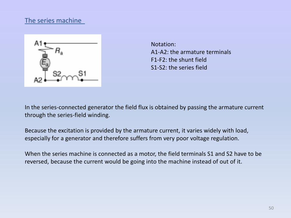
The series machine
Notation:A1-A2: the armature terminalsF1-F2: the shunt fieldS1-S2: the series field
In the series-connected generator the field flux is obtained by passing the armature current through the series-field winding.
Because the excitation is provided by the armature current, it varies widely with load, especially for a generator and therefore suffers from very poor voltage regulation.
When the series machine is connected as a motor, the field terminals S1 and S2 have to be reversed, because the current would be going into the machine instead of out of it.
50
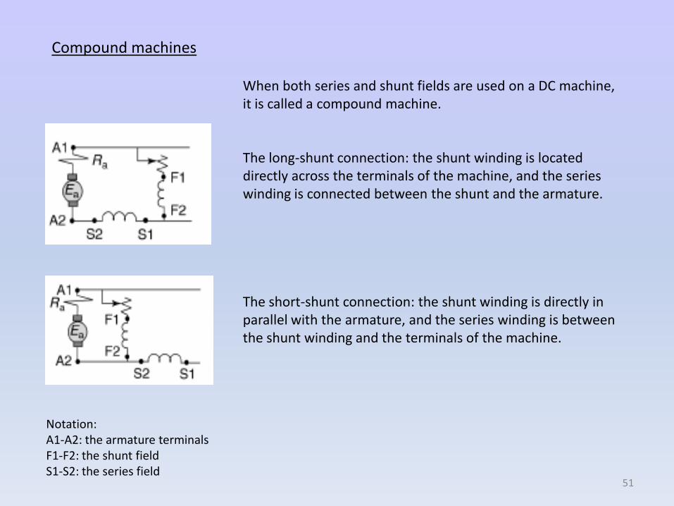
When both series and shunt fields are used on a DC machine, it is called a compound machine.
The long-shunt connection: the shunt winding is located directly across the terminals of the machine, and the serieswinding is connected between the shunt and the armature.
The short-shunt connection: the shunt winding is directly in parallel with the armature, and the series winding is between the shunt winding and the terminals of the machine.
Compound machines
Notation:A1-A2: the armature terminalsF1-F2: the shunt fieldS1-S2: the series field
51
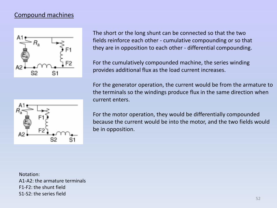
The short or the long shunt can be connected so that the two fields reinforce each other - cumulative compounding or so that they are in opposition to each other - differential compounding.
For the cumulatively compounded machine, the series winding provides additional flux as the load current increases.
For the generator operation, the current would be from the armature to the terminals so the windings produce flux in the same direction when current enters.
For the motor operation, they would be differentially compounded because the current would be into the motor, and the two fields would be in opposition.
Compound machines
Notation:A1-A2: the armature terminalsF1-F2: the shunt fieldS1-S2: the series field
52
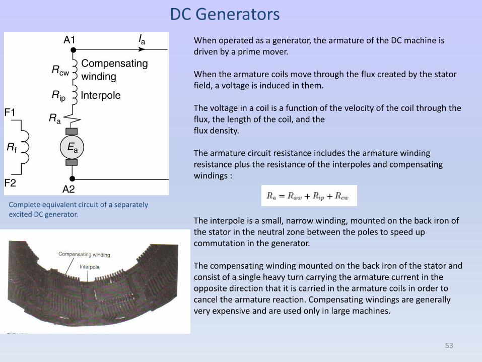
DC GeneratorsWhen operated as a generator, the armature of the DC machine is driven by a prime mover.
When the armature coils move through the flux created by the stator field, a voltage is induced in them.
The voltage in a coil is a function of the velocity of the coil through the flux, the length of the coil, and the flux density.
The armature circuit resistance includes the armature winding resistance plus the resistance of the interpoles and compensating windings :
The interpole is a small, narrow winding, mounted on the back iron of the stator in the neutral zone between the poles to speed up commutation in the generator.
The compensating winding mounted on the back iron of the stator and consist of a single heavy turn carrying the armature current in the opposite direction that it is carried in the armature coils in order to cancel the armature reaction. Compensating windings are generally very expensive and are used only in large machines.
Complete equivalent circuit of a separately excited DC generator.
53
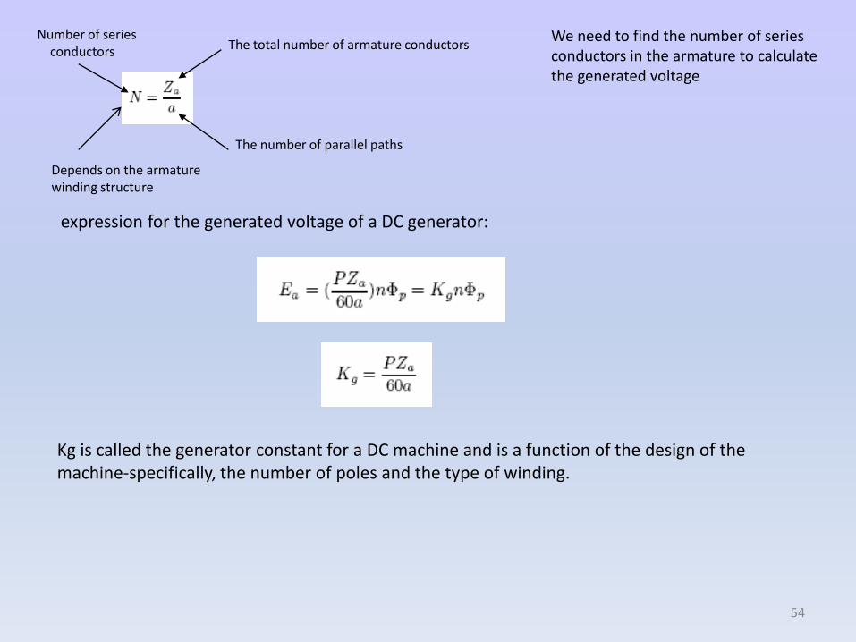
The total number of armature conductors
The number of parallel paths
Number of series conductors
expression for the generated voltage of a DC generator:
Kg is called the generator constant for a DC machine and is a function of the design of the machine-specifically, the number of poles and the type of winding.
54
We need to find the number of series conductors in the armature to calculate the generated voltage
Depends on the armature winding structure
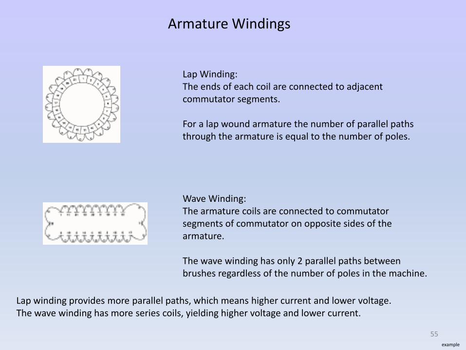
Armature Windings
Lap Winding:The ends of each coil are connected to adjacent commutator segments.
For a lap wound armature the number of parallel pathsthrough the armature is equal to the number of poles.
Wave Winding:The armature coils are connected to commutator segments of commutator on opposite sides of the armature.
The wave winding has only 2 parallel paths between brushes regardless of the number of poles in the machine.
Lap winding provides more parallel paths, which means higher current and lower voltage.The wave winding has more series coils, yielding higher voltage and lower current.
example
55
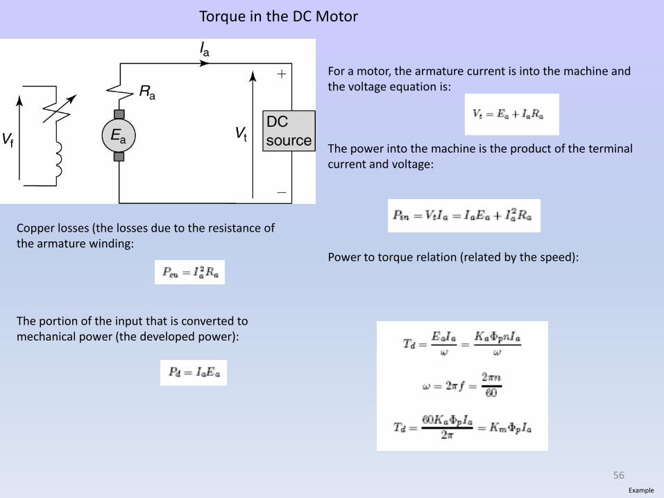
Torque in the DC Motor
For a motor, the armature current is into the machine and the voltage equation is:
The power into the machine is the product of the terminal current and voltage:
Power to torque relation (related by the speed):
Copper losses (the losses due to the resistance of the armature winding:
The portion of the input that is converted to mechanical power (the developed power):
Example
56
DC Motor Speed Characteristics
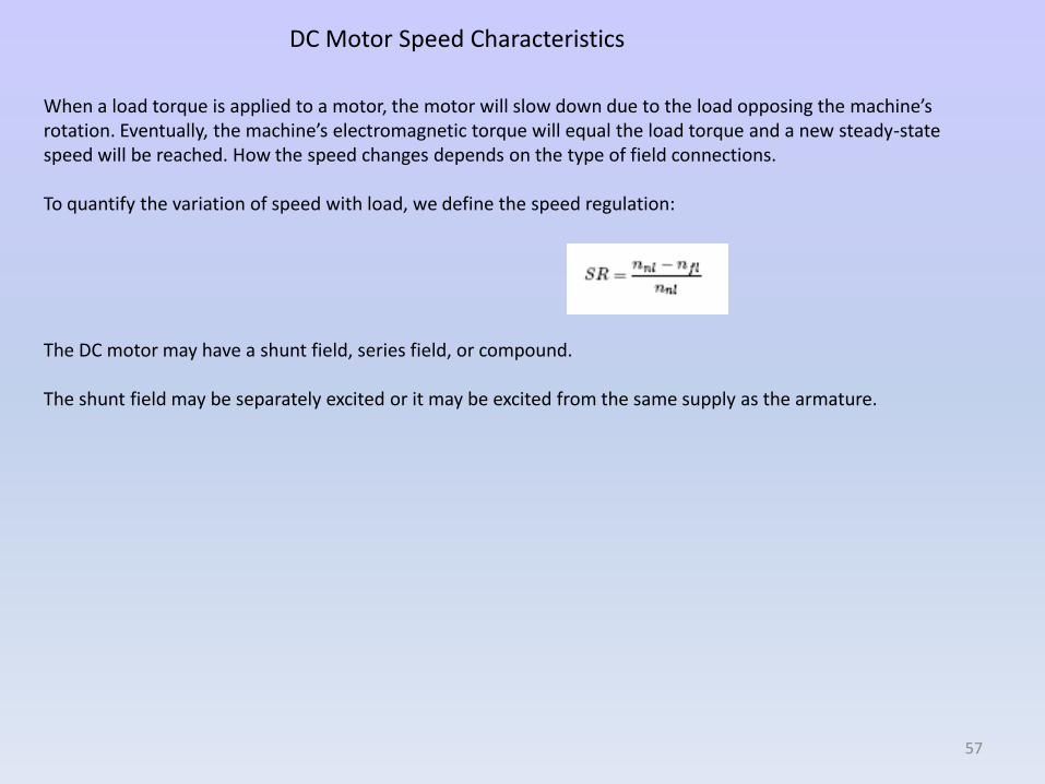
When a load torque is applied to a motor, the motor will slow down due to the load opposing the machine’s rotation. Eventually, the machine’s electromagnetic torque will equal the load torque and a new steady-state speed will be reached. How the speed changes depends on the type of field connections.
To quantify the variation of speed with load, we define the speed regulation:
The DC motor may have a shunt field, series field, or compound.
The shunt field may be separately excited or it may be excited from the same supply as the armature.
57
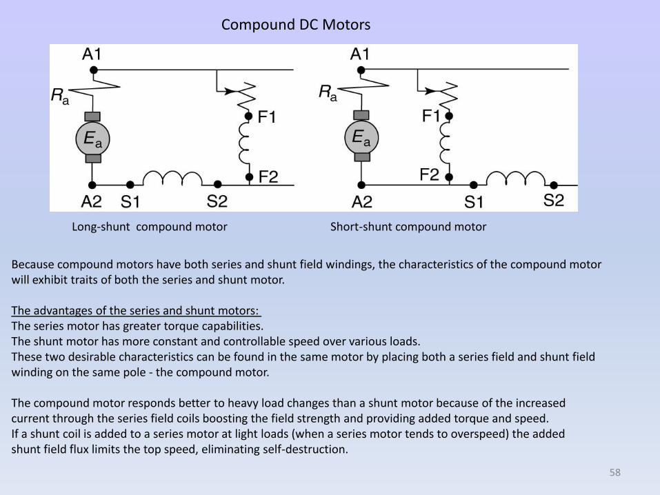
Compound DC Motors
Because compound motors have both series and shunt field windings, the characteristics of the compound motor will exhibit traits of both the series and shunt motor.
The advantages of the series and shunt motors: The series motor has greater torque capabilities.The shunt motor has more constant and controllable speed over various loads. These two desirable characteristics can be found in the same motor by placing both a series field and shunt field winding on the same pole - the compound motor.
The compound motor responds better to heavy load changes than a shunt motor because of the increased current through the series field coils boosting the field strength and providing added torque and speed. If a shunt coil is added to a series motor at light loads (when a series motor tends to overspeed) the added shunt field flux limits the top speed, eliminating self-destruction.
Long-shunt compound motor Short-shunt compound motor
58
59
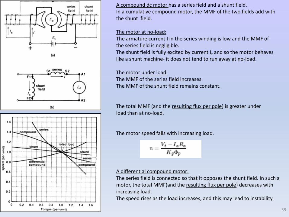
A compound dc motor has a series field and a shunt field. In a cumulative compound motor, the MMF of the two fields add with the shunt field.
The motor at no-load: The armature current I in the series winding is low and the MMF of the series field is negligible. The shunt field is fully excited by current Ix and so the motor behaves like a shunt machine- it does not tend to run away at no-load.
The motor under load: The MMF of the series field increases.The MMF of the shunt field remains constant.
The total MMF (and the resulting flux per pole) is greater under load than at no-load.
The motor speed falls with increasing load.
A differential compound motor:The series field is connected so that it opposes the shunt field. In such a motor, the total MMF(and the resulting flux per pole) decreases with increasing load. The speed rises as the load increases, and this may lead to instability.
DC Motor Speed Control
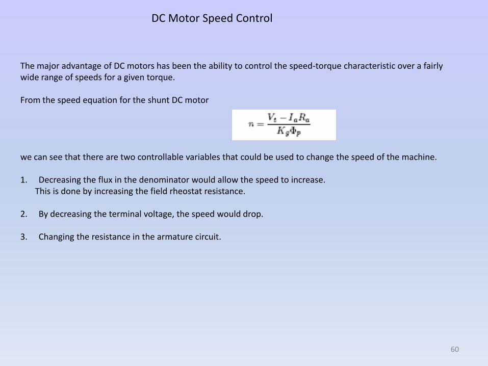
The major advantage of DC motors has been the ability to control the speed-torque characteristic over a fairly wide range of speeds for a given torque.
From the speed equation for the shunt DC motor
we can see that there are two controllable variables that could be used to change the speed of the machine.
1. Decreasing the flux in the denominator would allow the speed to increase. This is done by increasing the field rheostat resistance.
2. By decreasing the terminal voltage, the speed would drop.
3. Changing the resistance in the armature circuit.
60
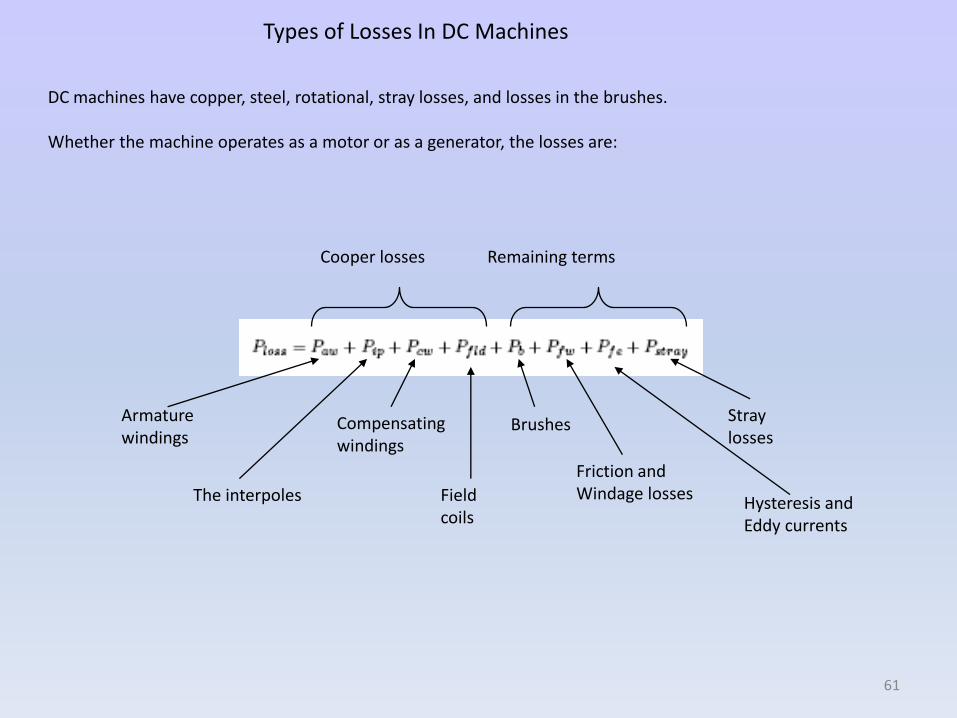
Types of Losses In DC Machines
DC machines have copper, steel, rotational, stray losses, and losses in the brushes.
Whether the machine operates as a motor or as a generator, the losses are:
Cooper losses Remaining terms
Armature windings
The interpoles
Compensating windings
Fieldcoils
Brushes
Friction andWindage losses
Straylosses
Hysteresis andEddy currents
61
Related Documents