EET 204 Electromechanical Devices and Systems Lecture 2 –Sensors Prof. M. Higazi

EET 204 Electromechanical Devices and Systems Lecture 2 –Sensors Prof. M. Higazi.
Dec 25, 2015
Welcome message from author
This document is posted to help you gain knowledge. Please leave a comment to let me know what you think about it! Share it to your friends and learn new things together.
Transcript

EET 204Electromechanical Devices and
Systems
Lecture 2 –Sensors
Prof. M. Higazi
Sensor – Definitions
• A sensor is a device that measures some physical quantity and converts it into a signal that may inform a control system
• A sensor informs the control system about what is actually occurring.
• What is the difference between a sensor and a transducer?
– A sensor consists of a transducer (sensor is also known as a transducer)
– a sensor is the complete assembly required to detect and communicate a particular event
– A transducer converts one form of energy to another– A transducer is the element within that assembly which accomplishes only the
detection of the event
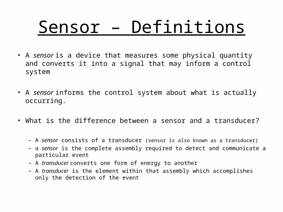
Sensors - Theory
• Sensors allow electronic circuits to communicate with the outside world.
• This is done by an electrical signal being produced or an existing electrical signal being altered in response to sensing some external condition.
• If a sensor produces an electrical signal in response to some external condition then it is actually a transducer as well as a sensor.
• An example of this would be a photo-sensor, which converts light energy into electrical energy.
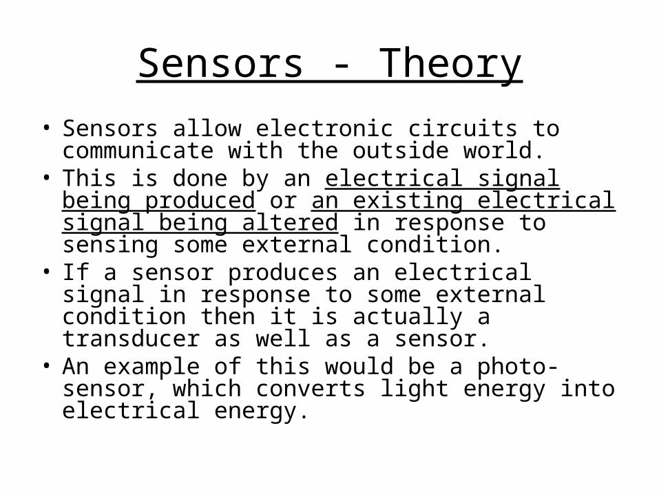
Sensors – Theory Cont.
• There are two basic types of sensors: analog and digital.• A sensor is sensitive to some measured property which
may change in quantity.• Sensitivity is the ratio between the output signal and
measured property.• The sensor’s sensitivity determines its output change
when the measured quantity changes.• For instance, if the mercury in a thermometer changes
by 5º if dropped 5cm, its sensitivity is 5cm/5º.• For a sensor to function accurately, it must be insensitive
to all properties, except its own measured property.

Sensors – Physical Quantities• Since sensors are a type of transducer, they change one form of energy to another.
• Because of this, sensors are classified according to the type of energy transfer that they detect.
• Some physical quantities or energy transfers that sensors are capable of detecting are:
– Temperature– Liquid– Light– Pressure– Chemical– Position– Distance– Sound– Motion– Electricity– Magnetism– And much more…
Sensors - Types
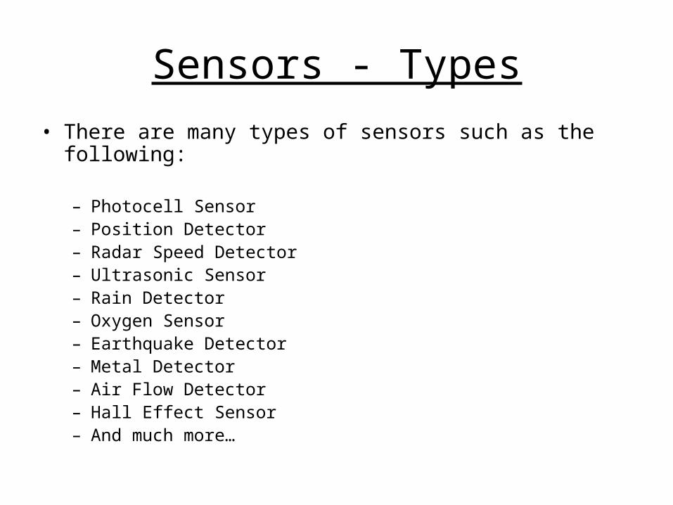
• There are many types of sensors such as the following:
– Photocell Sensor– Position Detector– Radar Speed Detector– Ultrasonic Sensor– Rain Detector– Oxygen Sensor– Earthquake Detector– Metal Detector– Air Flow Detector– Hall Effect Sensor– And much more…

Sensors - Appliances
• Sensors are widely used for a large variety of appliances such as:
– Medicine– Robotics– Aerospace– Security– Industry– Machines– Automobiles– Computers– And much more…
Position Sensors
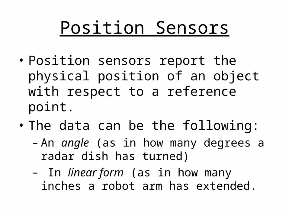
• Position sensors report the physical position of an object with respect to a reference point.
• The data can be the following:– An angle (as in how many degrees a radar
dish has turned)– In linear form (as in how many inches a robot
arm has extended.

Position Sensors – Pots.
• Potentiometer– a three-terminal resistor with a sliding contact that
forms an adjustable voltage divider– Used to convert rotary or linear displacement to a
voltage– Resistance value can also be converted to a voltage– Used to control electrical devices such as volume
controls on audio equipment– Used to detect angular position (i.e. of a robot arm,
etc.)
Position Sensors – Pots.
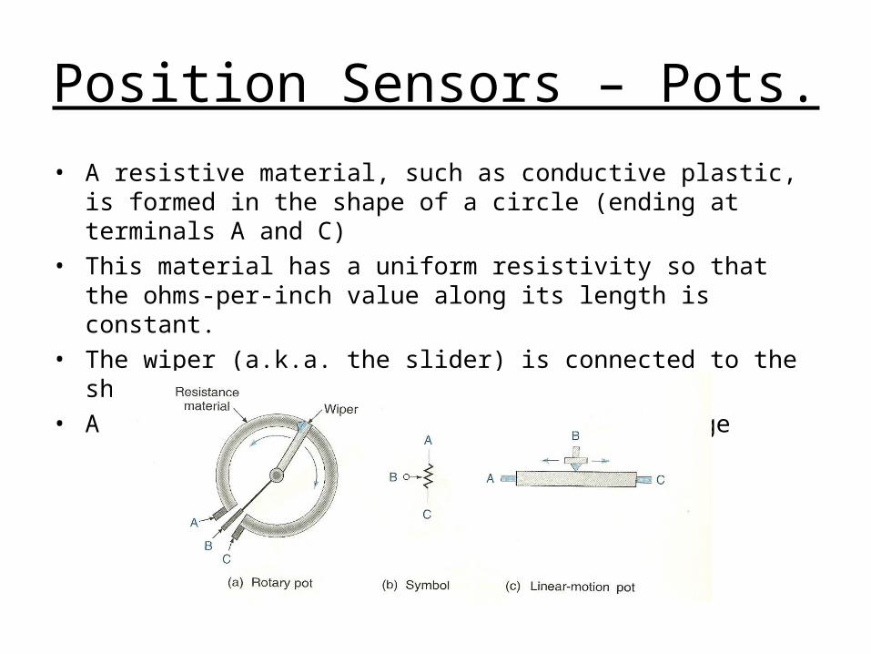
• A resistive material, such as conductive plastic, is formed in the shape of a circle (ending at terminals A and C)
• This material has a uniform resistivity so that the ohms-per-inch value along its length is constant.
• The wiper (a.k.a. the slider) is connected to the shaft• A “single-turn pot.” has 350 of useful range
Position Sensors – Pots.
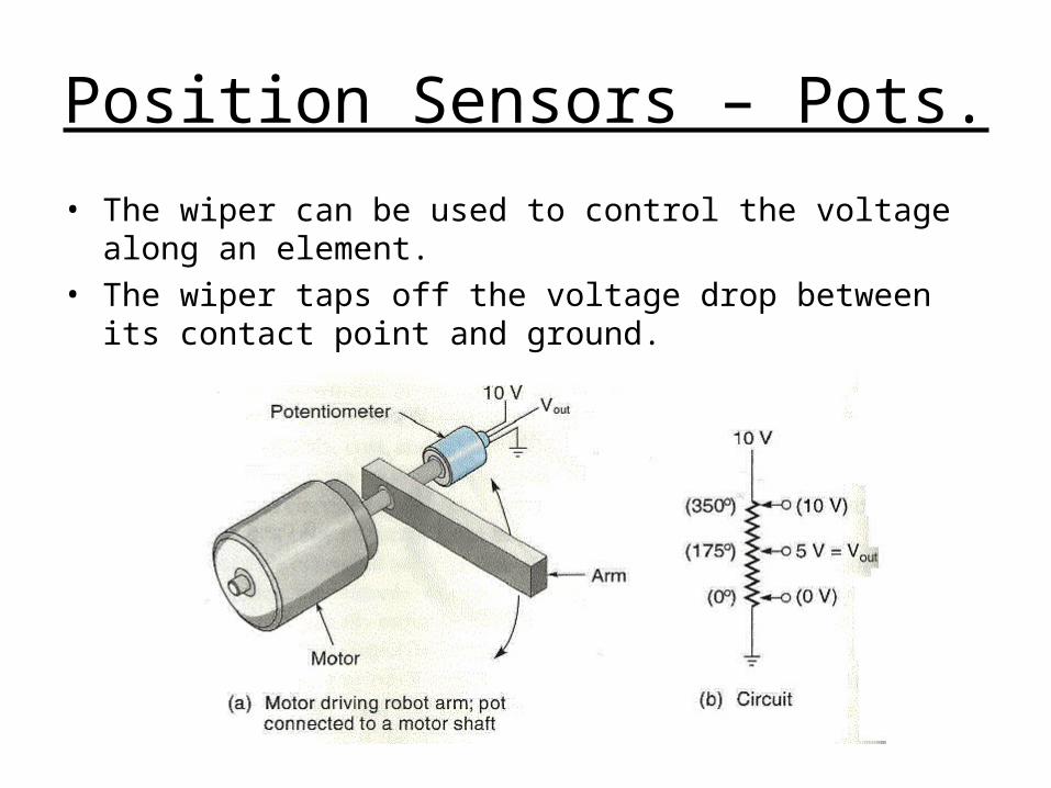
• The wiper can be used to control the voltage along an element.
• The wiper taps off the voltage drop between its contact point and ground.

Position Sensors – Pots.
• Example
A pot is supplied with 10 V and is set at 97. The range of this single-turn pot is 350 . Calculate the output voltage.
Solution:
/0286.0350
10Vdc
Vdc
input
outputTFpot
VdcVdcTFatvoltagePot pot 77.297/0286.097)97(
Position Sensors – Pots.
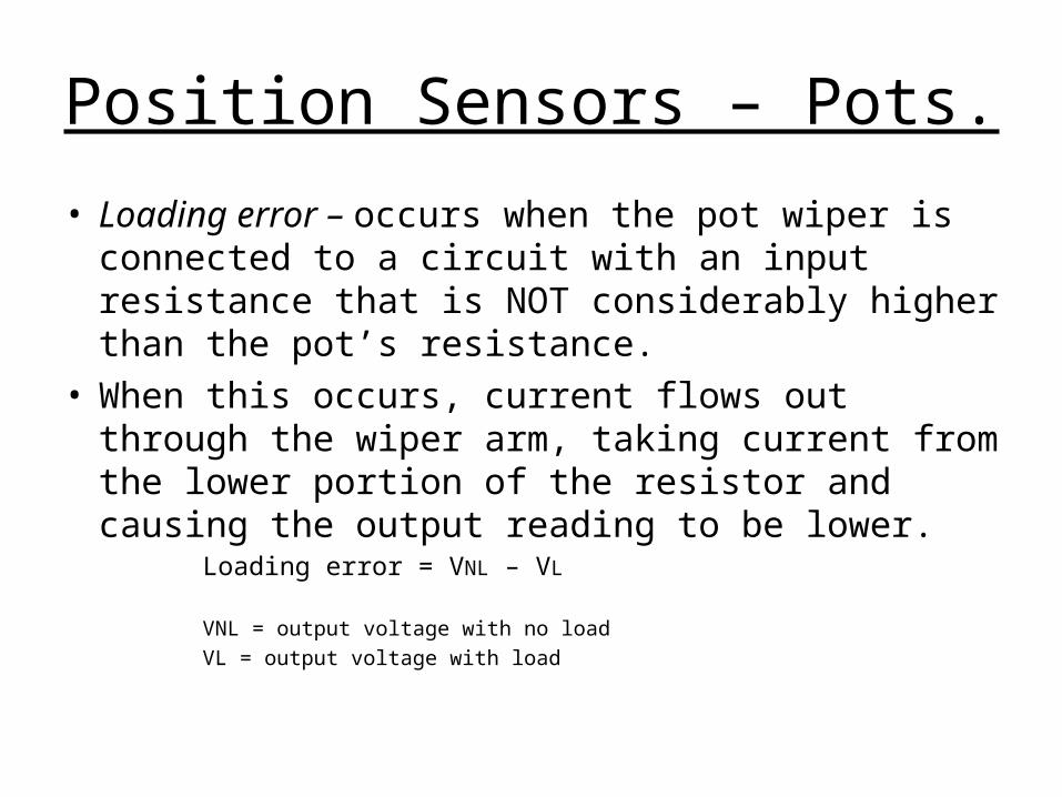
• Loading error – occurs when the pot wiper is connected to a circuit with an input resistance that is NOT considerably higher than the pot’s resistance.
• When this occurs, current flows out through the wiper arm, taking current from the lower portion of the resistor and causing the output reading to be lower.
Loading error = VNL – VL
VNL = output voltage with no load
VL = output voltage with load
Position Sensors – Pots.
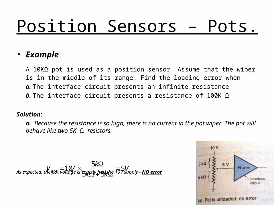
• Example
A 10KΩ pot is used as a position sensor. Assume that the wiper is in the middle of its range. Find the loading error when
a. The interface circuit presents an infinite resistance
b. The interface circuit presents a resistance of 100K Ω
Solution:
a. Because the resistance is so high, there is no current in the pot wiper. The pot will behave like two 5K Ω resistors.
As expected, the pot voltage is exactly half the 10V supply - NO error
Vkk
kVVpot 5
55
510
Position Sensors – Pots.
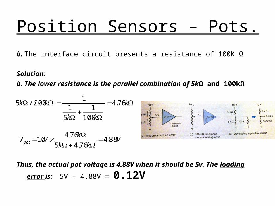
b. The interface circuit presents a resistance of 100K Ω
Solution:
b. The lower resistance is the parallel combination of 5kΩ and 100kΩ
Thus, the actual pot voltage is 4.88V when it should be 5v. The loading
error is: 5V – 4.88V = 0.12V
k
kk
kk 76.4
1001
51
1100//5
Vkk
kVVpot 88.4
76.45
76.410

Position Sensors – Pots.
• Potentiometers cannot be made perfectly linear
• Linearity error – the difference between what the angle really is and what the pot
reports it to be– Determines the accuracy of a sensor
totalR
RerrorLinearity
100
total
errorLinearity 100
OR
R = maximum resistance errorRtotal = total pot resistance
= maximum angle error (in degrees)total = total range of the pot (in degrees)
Position Sensors – Pots.
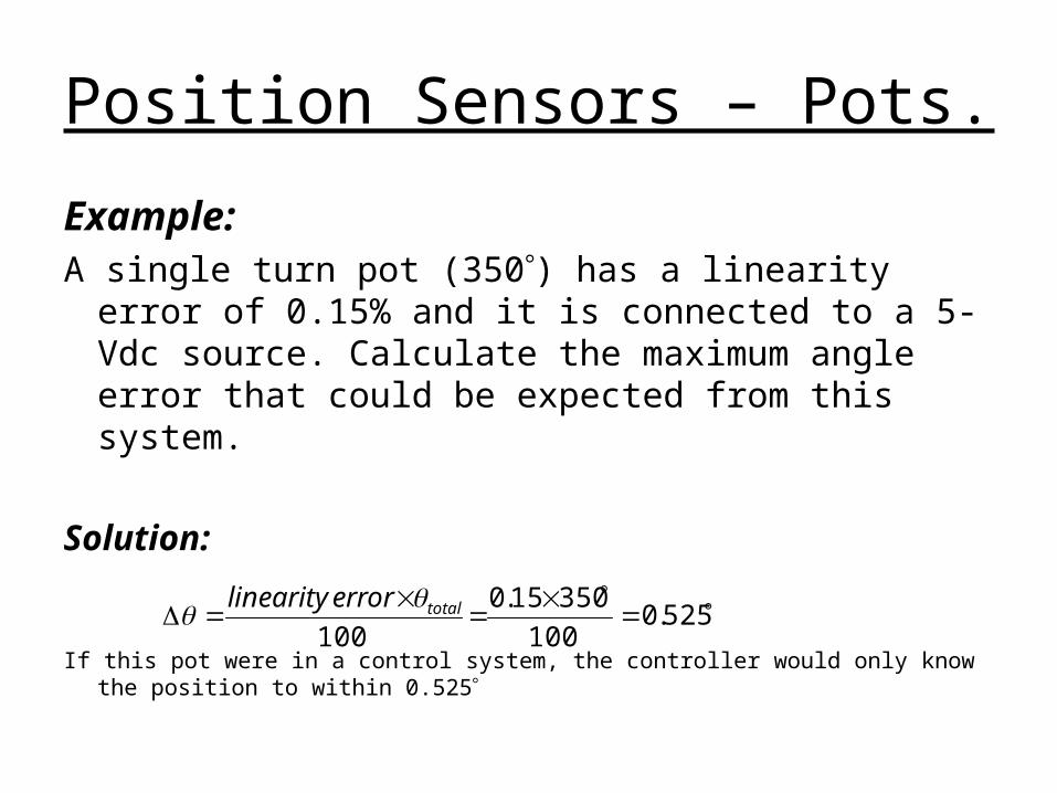
Example:A single turn pot (350) has a linearity error of 0.15%
and it is connected to a 5-Vdc source. Calculate the maximum angle error that could be expected from this system.
Solution:
If this pot were in a control system, the controller would only know the position to within 0.525
525.0100
35015.0
100totalerrorlinearity

Position Sensors – Pots.
• Resolution – Refers to the smallest increment of data that
can be detected and/or reported– For an analog device such as a pot, resolution
refers to the smallest change that can be measured (expressed in percentage)
100% Rtotal
Rinchangesmallestresolution
100
totalR
R
Position Sensors – Pots.
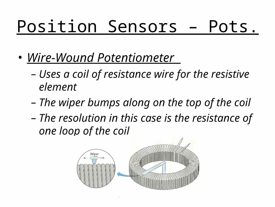
• Wire-Wound Potentiometer – Uses a coil of resistance wire for the resistive
element– The wiper bumps along on the top of the coil– The resolution in this case is the resistance of
one loop of the coil
Position Sensors – Pots.
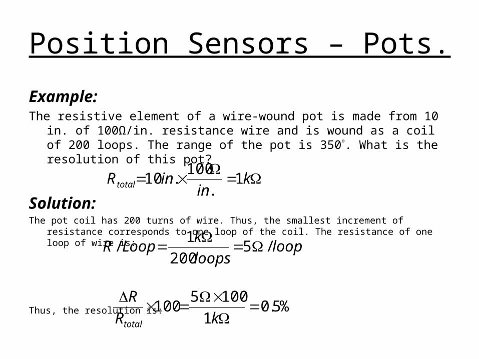
Example: The resistive element of a wire-wound pot is made from 10 in. of 100Ω/in.
resistance wire and is wound as a coil of 200 loops. The range of the pot is 350. What is the resolution of this pot?
Solution:The pot coil has 200 turns of wire. Thus, the smallest increment of resistance corresponds to one
loop of the coil. The resistance of one loop of wire is:
Thus, the resolution is:
kin
inR total 1.
100.10
looploops
kLoopR /5
200
1/
%5.01
1005100
kR
R
total
Position Sensors – Pots.
• If the wire-wound pot were to be used as a position sensor, it would be useful to know what the resolution is in degrees. The smallest measureable change corresponds to one loop of the resistance coil. And this pot divides 350 into 200 parts; therefore, the resolution in degrees would be 350/200 loops = 1.75 .
Position Sensors – Pots.
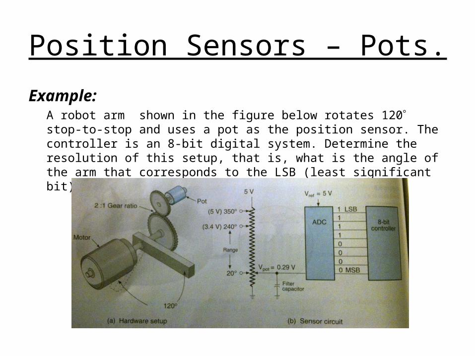
Example:A robot arm shown in the figure below rotates 120 stop-to-stop and uses a pot as the position sensor. The controller is an 8-bit digital system. Determine the resolution of this setup, that is, what is the angle of the arm that corresponds to the LSB (least significant bit)?
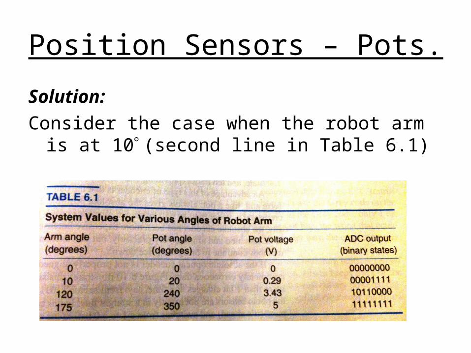
Position Sensors – Pots.
Solution:
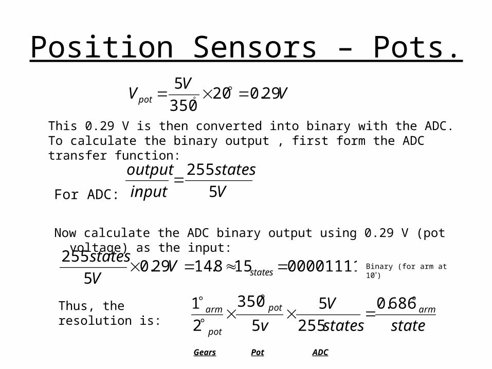
Consider the case when the robot arm is at 10 (second line in Table 6.1)
Position Sensors – Pots.
This 0.29 V is then converted into binary with the ADC. To calculate the binary output , first form the ADC transfer function:
For ADC:
Now calculate the ADC binary output using 0.29 V (pot voltage) as the input:
VV
Vpot 29.020350
5
V
states
input
output
5
255
00001111158.1429.05
255 statesV
V
statesBinary (for arm at 10)
Thus, the resolution is:
statestates
V
varmpot
pot
arm
686.0
255
5
5
350
2
1
Gears Pot ADC

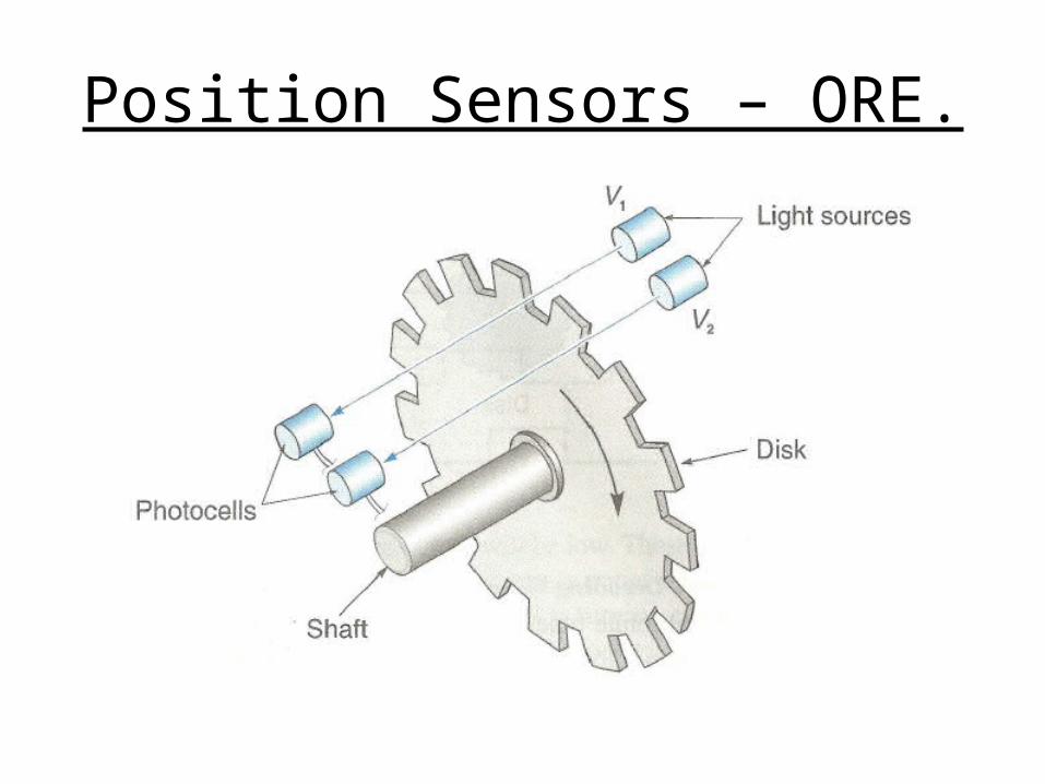
Position Sensors – ORE.
• Optical Rotary Encoders– Produces angular position data directly in digital form, eliminating any
need for ADC
– The design is comprised of a “code disk” attached to a shaft
– A light source and photocell arrangement are mounted so that the slots pass the light beam as the disk rotates
– The angle of the shaft is deduced from the output of the photocell
Position Sensors – ORE.
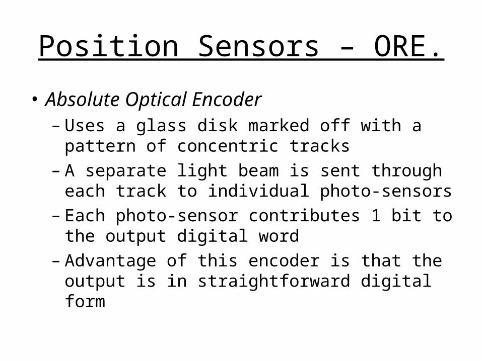
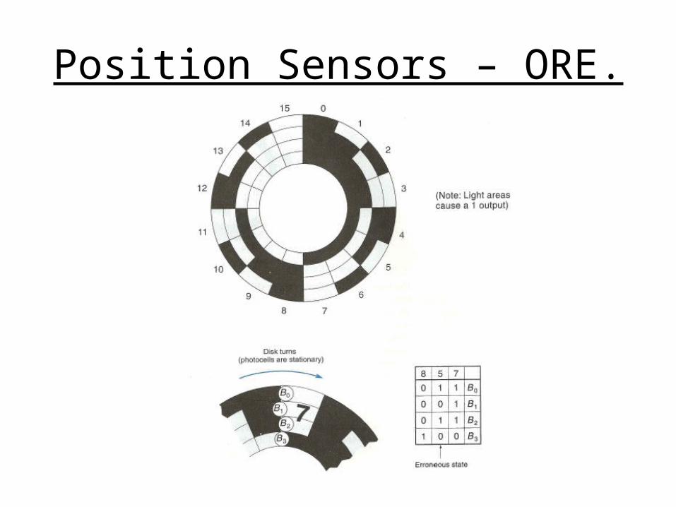
• Absolute Optical Encoder– Uses a glass disk marked off with a pattern of
concentric tracks– A separate light beam is sent through each
track to individual photo-sensors– Each photo-sensor contributes 1 bit to the
output digital word– Advantage of this encoder is that the output is
in straightforward digital form
Position Sensors – ORE.
Position Sensors – ORE.
• Incremental Optical Encoder– Has only one track of equally spaced slots– Position is determined by counting the
number of slots that pass a photo-sensor, where each slot represents a known angle
– Requires an initial reference point, which may come from a second sensor
– To track position, the controller must know the direction the disk is turning as well as the number of slots passed
Position Sensors – ORE.

Position Sensors – ORE.
Position Sensors – ORE.
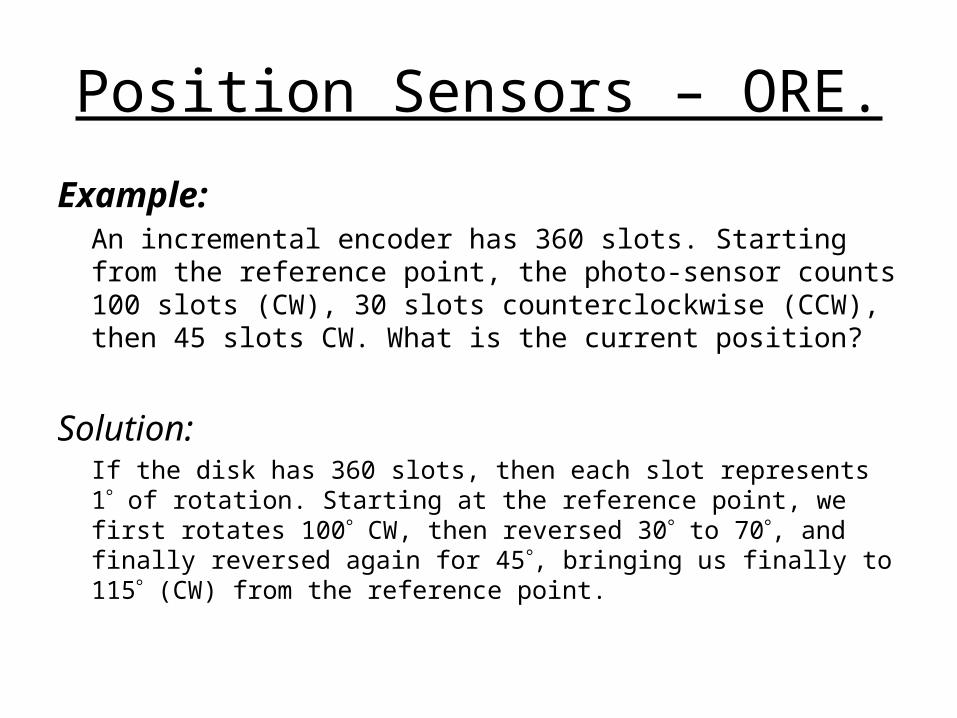
Example:An incremental encoder has 360 slots. Starting from the reference point, the photo-sensor counts 100 slots (CW), 30 slots counterclockwise (CCW), then 45 slots CW. What is the current position?
Solution:If the disk has 360 slots, then each slot represents 1 of rotation. Starting at the reference point, we first rotates 100 CW, then reversed 30 to 70, and finally reversed again for 45, bringing us finally to 115 (CW) from the reference point.
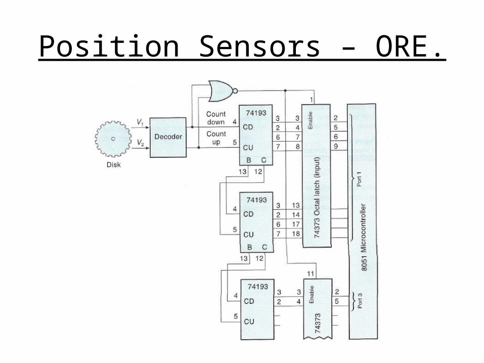
Position Sensors – ORE.
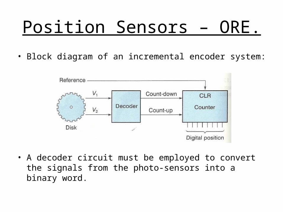
• Block diagram of an incremental encoder system:
• A decoder circuit must be employed to convert the signals from the photo-sensors into a binary word.
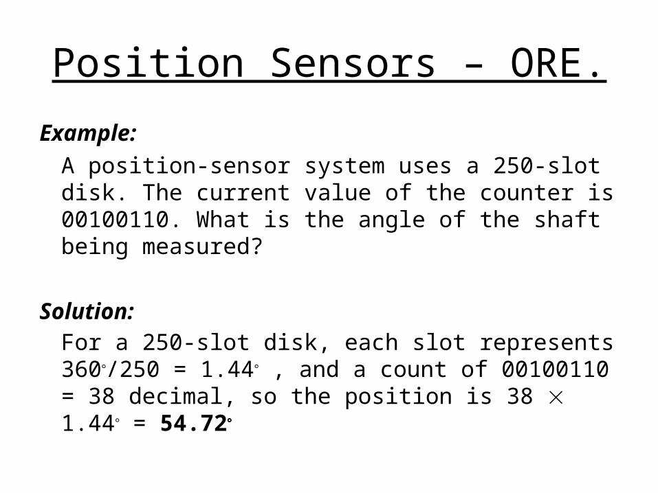
Position Sensors – ORE.
Example:
A position-sensor system uses a 250-slot disk. The current value of the counter is 00100110. What is the angle of the shaft being measured?
Solution:For a 250-slot disk, each slot represents 360/250 = 1.44 , and a count of 00100110 = 38 decimal, so the position is 38 1.44 = 54.72
Position Sensors – ORE.
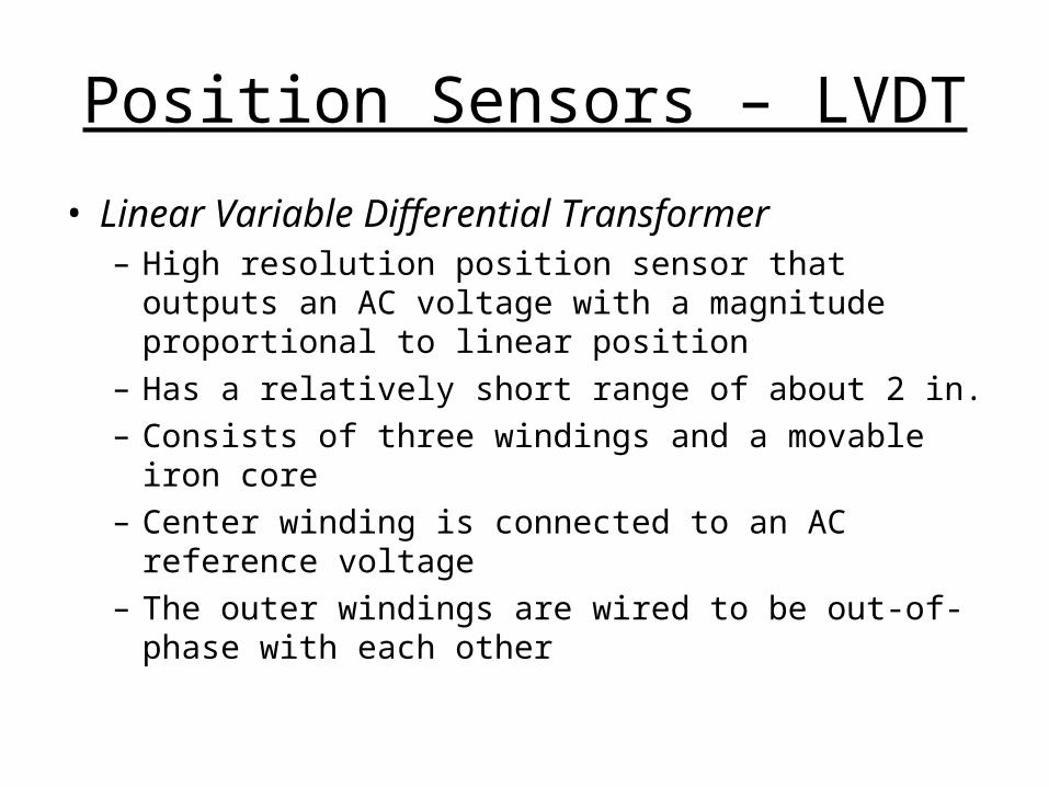
Position Sensors – LVDT
• Linear Variable Differential Transformer– High resolution position sensor that outputs an AC
voltage with a magnitude proportional to linear position
– Has a relatively short range of about 2 in.– Consists of three windings and a movable iron core– Center winding is connected to an AC reference
voltage– The outer windings are wired to be out-of-phase with
each other

Position Sensors – LVDT

Position Sensors – LVDT

Angular Velocity Sensors
• Angular Velocity Sensors– Also known as tachometers
– Devices that give an output proportional to angular velocity
– Widely used in motor-speed control systems
• Velocity in terms of position/angular sensors– The only components of velocity are position and time
12
12
tttVelocity
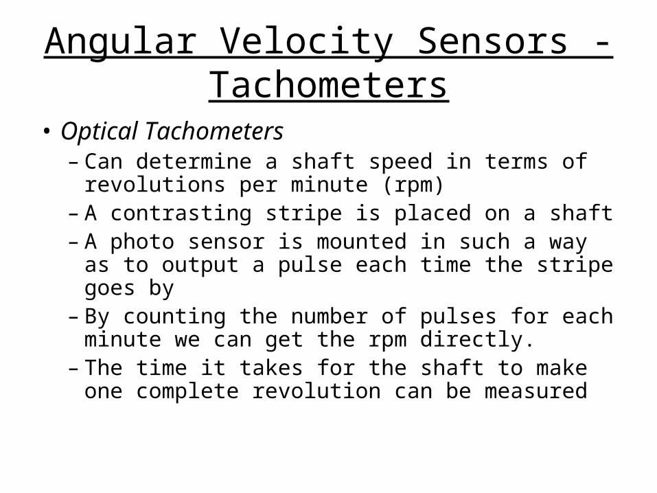
Angular Velocity Sensors - Tachometers
• Optical Tachometers– Can determine a shaft speed in terms of
revolutions per minute (rpm)– A contrasting stripe is placed on a shaft– A photo sensor is mounted in such a way as
to output a pulse each time the stripe goes by– By counting the number of pulses for each
minute we can get the rpm directly.– The time it takes for the shaft to make one
complete revolution can be measured

Angular Velocity Sensors - Tachometers
Angular Velocity Sensors - Tachometers
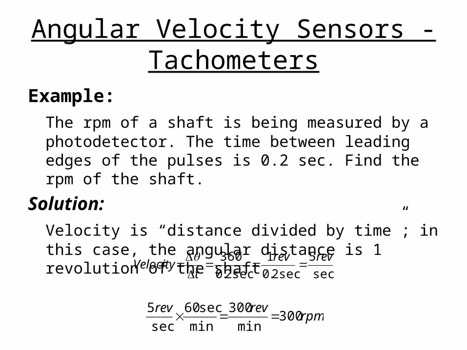
Example:
The rpm of a shaft is being measured by a photodetector. The time between leading edges of the pulses is 0.2 sec. Find the rpm of the shaft.
Solution:
Velocity is “distance divided by time”; in this case, the angular distance is 1 revolution of the shaft
sec
5
sec2.0
1
sec2.0
360 revrev
tVelocity
rpmrevrev
300min
300
min
sec60
sec
5
Angular Velocity Sensors - Tachometers
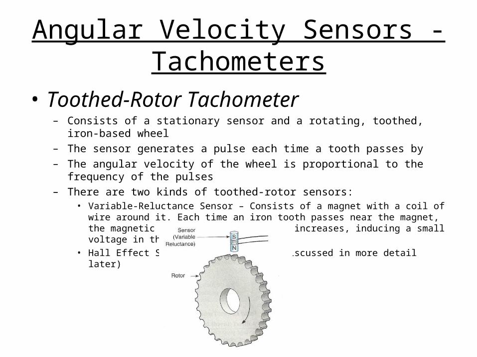
• Toothed-Rotor Tachometer– Consists of a stationary sensor and a rotating, toothed, iron-based wheel– The sensor generates a pulse each time a tooth passes by– The angular velocity of the wheel is proportional to the frequency of the pulses– There are two kinds of toothed-rotor sensors:
• Variable-Reluctance Sensor – Consists of a magnet with a coil of wire around it. Each time an iron tooth passes near the magnet, the magnetic field within the magnet increases, inducing a small voltage in the coil of wire.
• Hall Effect Sensor - (This will be discussed in more detail later)
Angular Velocity Sensors - Tachometers
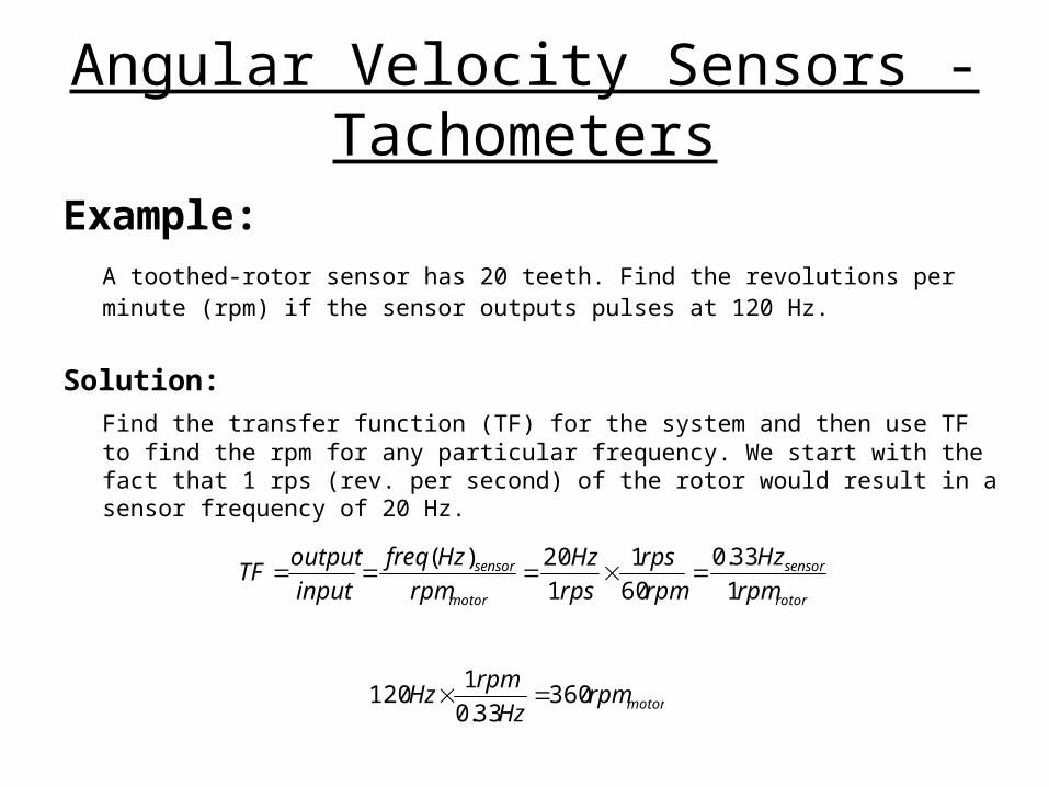
Example:A toothed-rotor sensor has 20 teeth. Find the revolutions per minute (rpm) if the sensor outputs pulses at 120 Hz.
Solution:
Find the transfer function (TF) for the system and then use TF to find the rpm for any particular frequency. We start with the fact that 1 rps (rev. per second) of the rotor would result in a sensor frequency of 20 Hz.
rotor
sensor
motor
sensor
rpm
Hz
rpm
rps
rps
Hz
rpm
Hzfreq
input
outputTF
1
33.0
60
1
1
20)(
motorrpmHz
rpmHz 360
33.0
1120
Angular Velocity Sensors - Tachometers
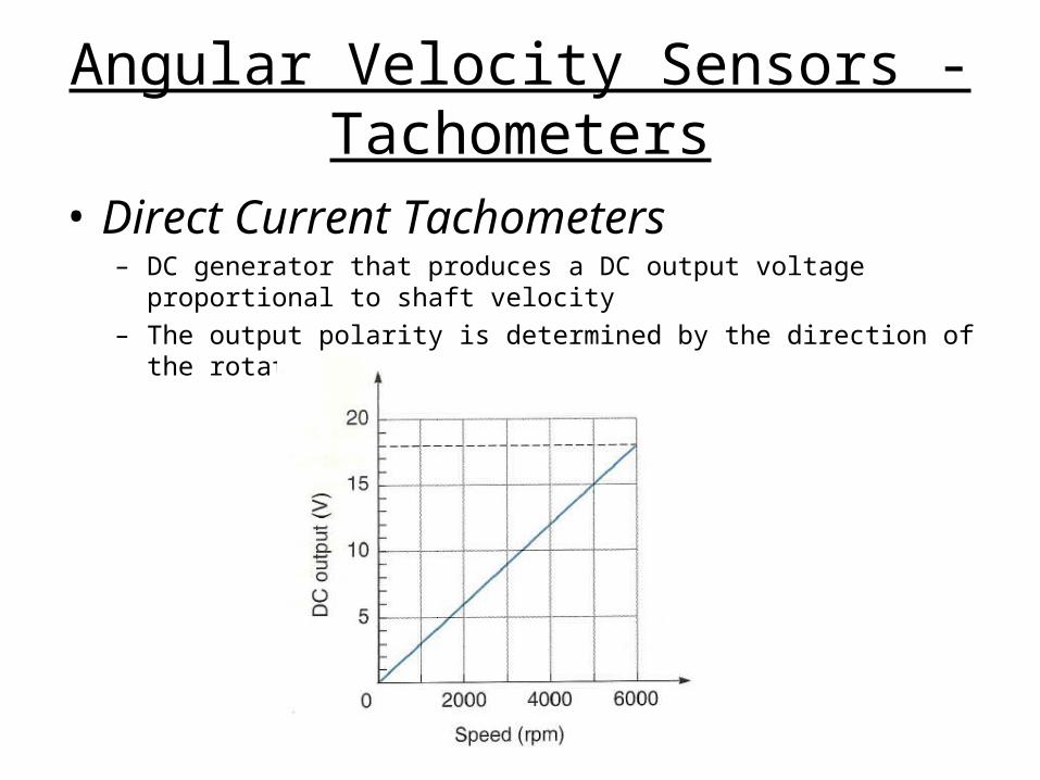
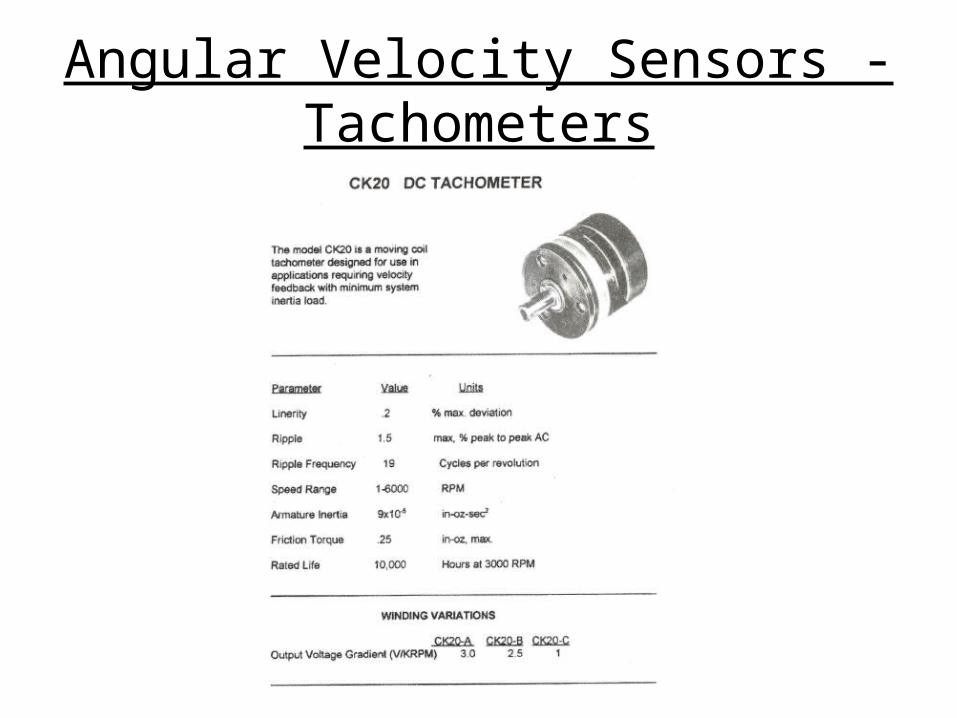
• Direct Current Tachometers– DC generator that produces a DC output voltage proportional to shaft
velocity
– The output polarity is determined by the direction of the rotation
Angular Velocity Sensors - Tachometers
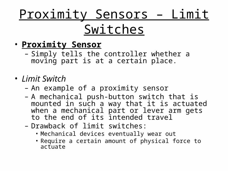
Proximity Sensors – Limit Switches
• Proximity Sensor– Simply tells the controller whether a moving part is at
a certain place.
• Limit Switch– An example of a proximity sensor– A mechanical push-button switch that is mounted in
such a way that it is actuated when a mechanical part or lever arm gets to the end of its intended travel
– Drawback of limit switches:• Mechanical devices eventually wear out• Require a certain amount of physical force to actuate

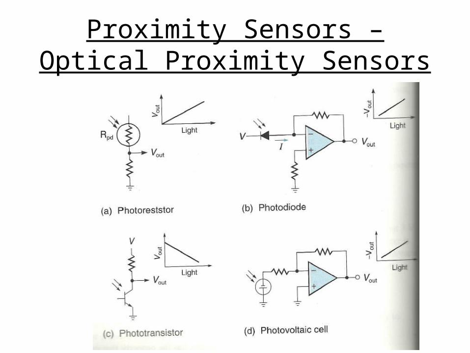
Proximity Sensors – Optical Proximity Sensors
• Optical Proximity Sensor– Use a light source and a photo-sensor that are mounted in such
a way that the object to be detected either cuts or reflects the light path.
– Four types of common photodetectors:• Photo-resistor – Its resistance decreases when the light level
increases• Photodiode – A light sensitive diode that is reverse-biased. The
reverse-leakage current is converted into an amplified voltage• Photo-transistor – Light effectively creates a base current by
generating electron-hole pairs in the CB junction. The more light, the more the transistor turns on
• Photovoltaic cell – Creates electrical power from light. The more light, the higher the voltage. (A solar cell is a photovoltaic cell)
Proximity Sensors – Optical Proximity Sensors
Proximity Sensors – Optical Proximity Sensors
Proximity Sensors – Optical Proximity Sensors
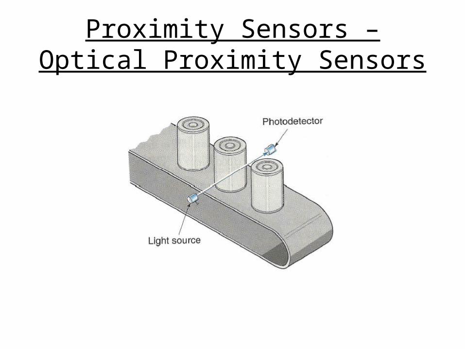
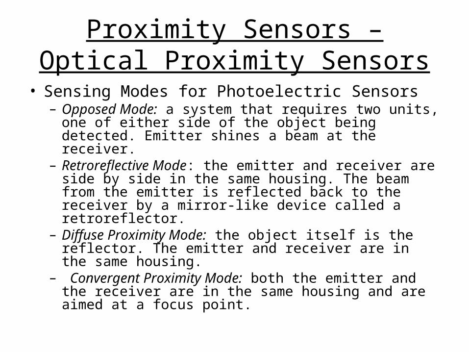
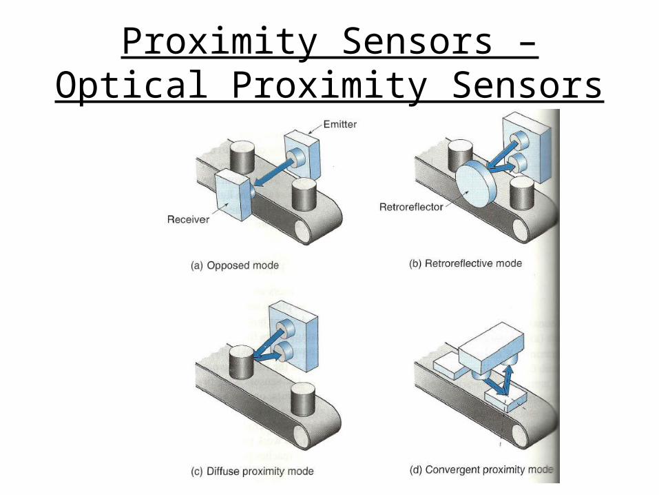
• Sensing Modes for Photoelectric Sensors– Opposed Mode: a system that requires two units, one
of either side of the object being detected. Emitter shines a beam at the receiver.
– Retroreflective Mode: the emitter and receiver are side by side in the same housing. The beam from the emitter is reflected back to the receiver by a mirror-like device called a retroreflector.
– Diffuse Proximity Mode: the object itself is the reflector. The emitter and receiver are in the same housing.
– Convergent Proximity Mode: both the emitter and the receiver are in the same housing and are aimed at a focus point.
Proximity Sensors – Optical Proximity Sensors
Proximity Sensors – Ultrasonic Proximity Sensors
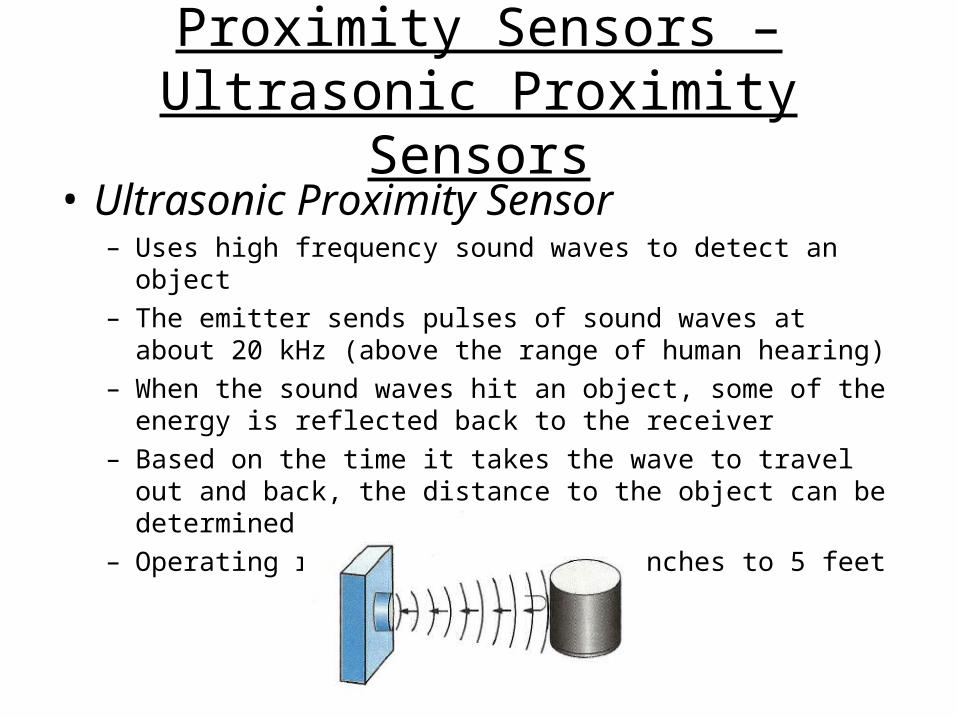
• Ultrasonic Proximity Sensor– Uses high frequency sound waves to detect an object– The emitter sends pulses of sound waves at about 20 kHz
(above the range of human hearing)– When the sound waves hit an object, some of the energy is
reflected back to the receiver– Based on the time it takes the wave to travel out and back, the
distance to the object can be determined– Operating range is typically 6 inches to 5 feet
Proximity Sensors – Inductive Proximity Sensors
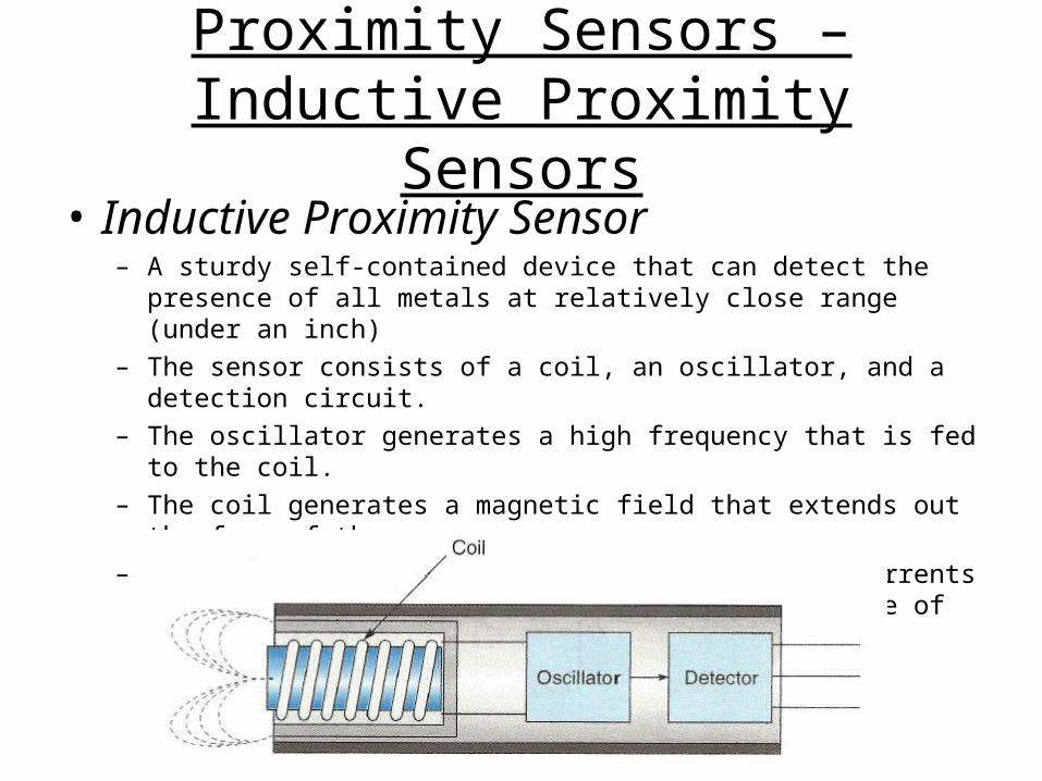
• Inductive Proximity Sensor– A sturdy self-contained device that can detect the presence of all metals
at relatively close range (under an inch)
– The sensor consists of a coil, an oscillator, and a detection circuit.
– The oscillator generates a high frequency that is fed to the coil.
– The coil generates a magnetic field that extends out the face of the sensor.
– If a metal object moves into the field, eddy currents are induced in the object, causing the magnitude of the coil oscillations to be reduced.

Proximity Sensors – Hall Effect Sensors
• Hall-Effect Proximity Sensor– Outputs a voltage when the detected magnetic field increases
– This is done either by moving a magnet or by changing the magnetic field path
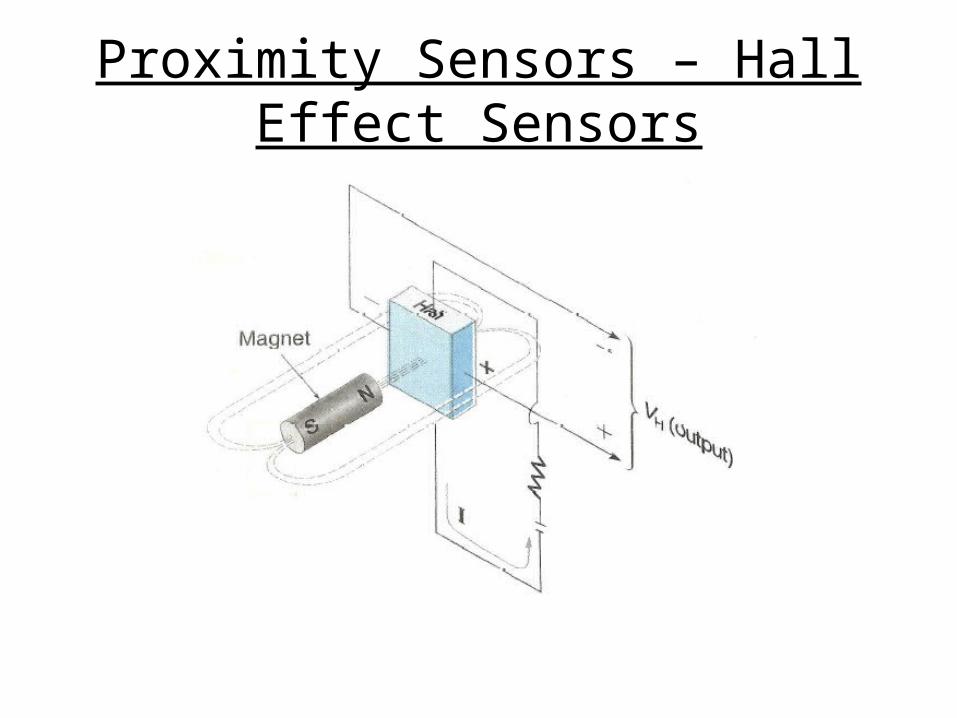
Proximity Sensors – Hall Effect Sensors
Proximity Sensors – Hall Effect Sensors
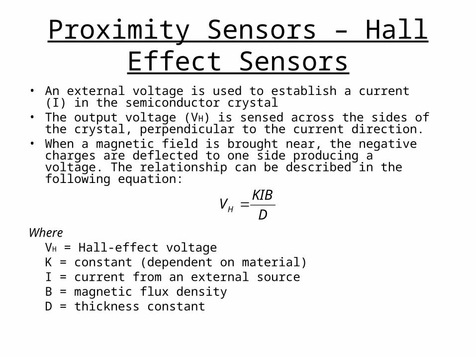
• An external voltage is used to establish a current (I) in the semiconductor crystal
• The output voltage (VH) is sensed across the sides of the crystal, perpendicular to the current direction.
• When a magnetic field is brought near, the negative charges are deflected to one side producing a voltage. The relationship can be described in the following equation:
WhereVH = Hall-effect voltageK = constant (dependent on material)I = current from an external sourceB = magnetic flux densityD = thickness constant
D
KIBVH
Temperature Sensors
• Temperature sensors give an output proportional to temperature.
• Most temperature sensors have a positive temperature coefficient, meaning that the sensor output goes up as the temperature goes up
• Some temperature sensors have a negative temperature coefficient, meaning that the sensor output goes down as the temperature goes up
• Many control systems require temperature sensors, especially for temperature-dependent applications
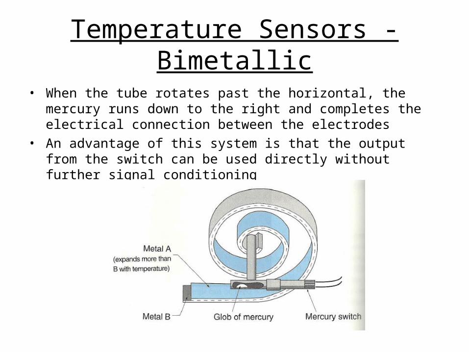
Temperature Sensors - Bimetallic
• Bimetallic Temperature Sensor– Consists of a bimetallic strip wound into a spiral– The bimetallic strip is a laminate of two metal with
different coefficients of thermal expansion– As temperature rises, the metal on the inside expands
more than the metal on the outside, and the spiral tends to straighten out
– Typically used for on-off control, such as in a household thermostat where a mercury switch is rocked from on to off
Temperature Sensors - Bimetallic
• When the tube rotates past the horizontal, the mercury runs down to the right and completes the electrical connection between the electrodes
• An advantage of this system is that the output from the switch can be used directly without further signal conditioning

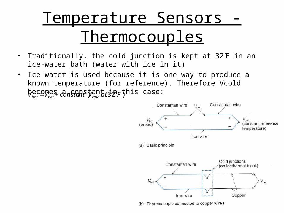
Temperature Sensors - Thermocouples
• Thermocouple– Used commonly in high-temperature situations
– Based on the Seebeck effect – a phenomenon whereby a voltage that is almost proportional to temperature can be produced from a circuit consisting of two dissimilar metal wires
– A thermocouple made from iron and constantan (an alloy) generates a voltage of approximately 35V/F
– The junctions at each end of the dissimilar metal wires produce a voltage
– One junction is called the hot junction (the junction on the probe) and the other junction is the cold junction (kept at some known reference temperature
– The actual difference between the junction voltages is known as Vnet, which is essentially the output voltage of this system.
coldhotnet VVV
Temperature Sensors - Thermocouples
• Traditionally, the cold junction is kept at 32F in an ice-water bath (water with ice in it)
• Ice water is used because it is one way to produce a known temperature (for reference). Therefore Vcold becomes a constant in this case:
)32( FatVntconstaVV coldnethot
Temperature Sensors - Thermocouples
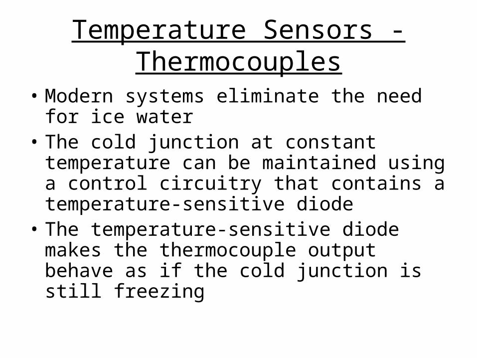
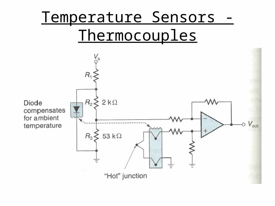
• Modern systems eliminate the need for ice water
• The cold junction at constant temperature can be maintained using a control circuitry that contains a temperature-sensitive diode
• The temperature-sensitive diode makes the thermocouple output behave as if the cold junction is still freezing
Temperature Sensors - Thermocouples
Temperature Sensors - Thermocouples
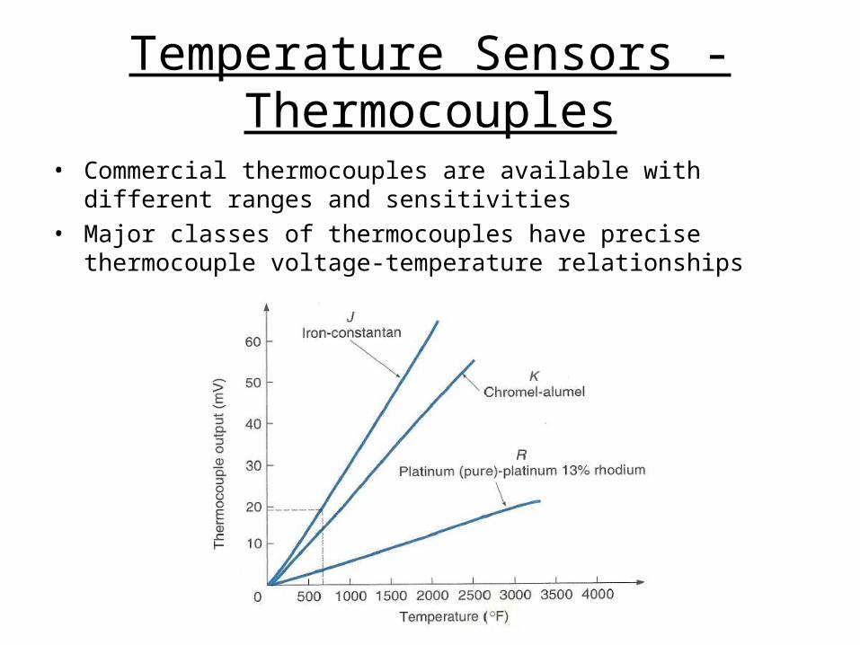
• Commercial thermocouples are available with different ranges and sensitivities
• Major classes of thermocouples have precise thermocouple voltage-temperature relationships

Temperature Sensors - Thermocouples
• Measuring oven temperature with a thermocouple
Temperature Sensors - Thermocouples
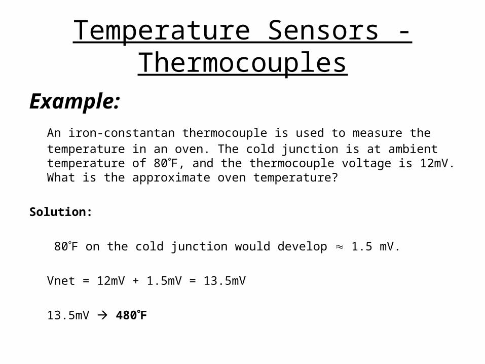
Example: An iron-constantan thermocouple is used to measure the temperature in an oven. The cold junction is at ambient temperature of 80F, and the thermocouple voltage is 12mV. What is the approximate oven temperature?
Solution:
80F on the cold junction would develop 1.5 mV.
Vnet = 12mV + 1.5mV = 13.5mV
13.5mV 480F
Temperature Sensors - RTD
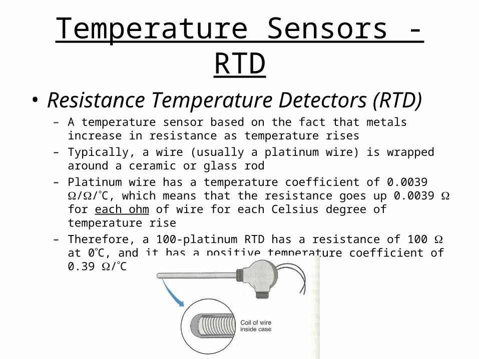
• Resistance Temperature Detectors (RTD)– A temperature sensor based on the fact that metals increase in resistance
as temperature rises
– Typically, a wire (usually a platinum wire) is wrapped around a ceramic or glass rod
– Platinum wire has a temperature coefficient of 0.0039 //C, which means that the resistance goes up 0.0039 for each ohm of wire for each Celsius degree of temperature rise
– Therefore, a 100-platinum RTD has a resistance of 100 at 0C, and it has a positive temperature coefficient of 0.39 /C
Temperature Sensors - RTD
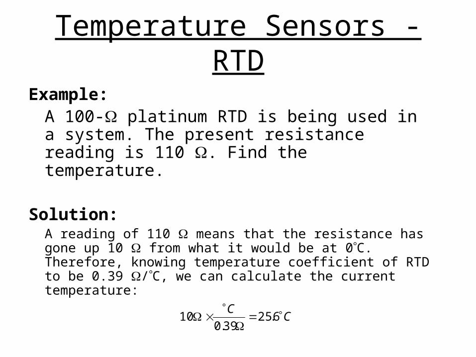
Example:A 100- platinum RTD is being used in a system. The present resistance reading is 110 . Find the temperature.
Solution:A reading of 110 means that the resistance has gone up 10 from what it would be at 0C. Therefore, knowing temperature coefficient of RTD to be 0.39 /C, we can calculate the current temperature:
CC
6.25
39.010

Temperature Sensors - Thermistors
• Thermistors– A two-terminal device that changes resistance
with temperature– Made of oxide-based semiconductor materials– Thermistors are non-linear; used to get an
accurate temperature reading to indicate temperature changes
– Thermistors have a negative temperature coefficient; meaning the resistance decreases as the temperature increases

Temperature Sensors - Thermistors
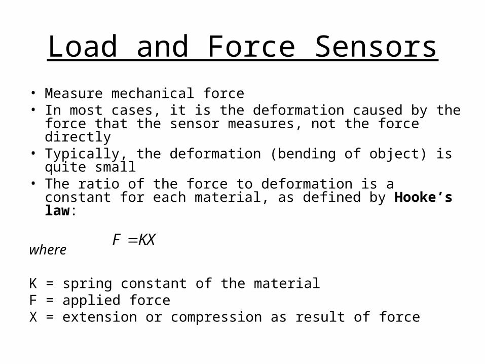
Load and Force Sensors
• Measure mechanical force• In most cases, it is the deformation caused by the force
that the sensor measures, not the force directly• Typically, the deformation (bending of object) is quite small• The ratio of the force to deformation is a constant for each
material, as defined by Hooke’s law:
where
K = spring constant of the materialF = applied forceX = extension or compression as result of force
KXF

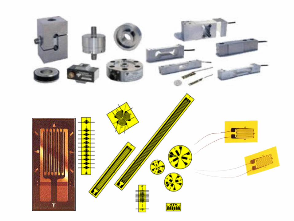
Load and Force Sensors – Strain Gauges
• Bounded-Wire Strain Gauges– Used to measure a wide range of forces from 10 lb to many tons– Consists of a thin wire looped back and forth a few times and
cemented to a thin paper backing– The entire strain gauge is securely bonded to some structural
object and will detect deformation that may take place– If the object is put under tension, the gauge will stretch and
lengthen the wires– The wires not only get slightly longer, but also thinner– Both these actions cause the total wire resistance to rise as
defined by the basic resistance equation:
A
LR
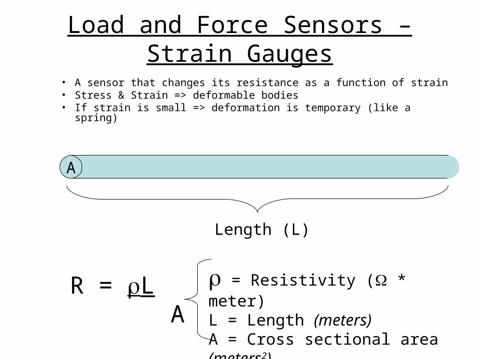
• A sensor that changes its resistance as a function of strain• Stress & Strain => deformable bodies• If strain is small => deformation is temporary (like a spring)
R = L A
= Resistivity ( * meter)L = Length (meters)A = Cross sectional area (meters2)
A
Length (L)
Load and Force Sensors – Strain Gauges
Load and Force Sensors – Strain Gauges
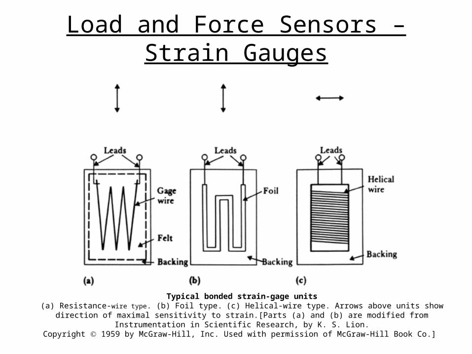
Typical bonded strain-gage units(a) Resistance-wire type. (b) Foil type. (c) Helical-wire type. Arrows above units show direction of maximal sensitivity to strain.
[Parts (a) and (b) are modified from Instrumentation in Scientific Research, by K. S. Lion.Copyright 1959 by McGraw-Hill, Inc. Used with permission of McGraw-Hill Book Co.]
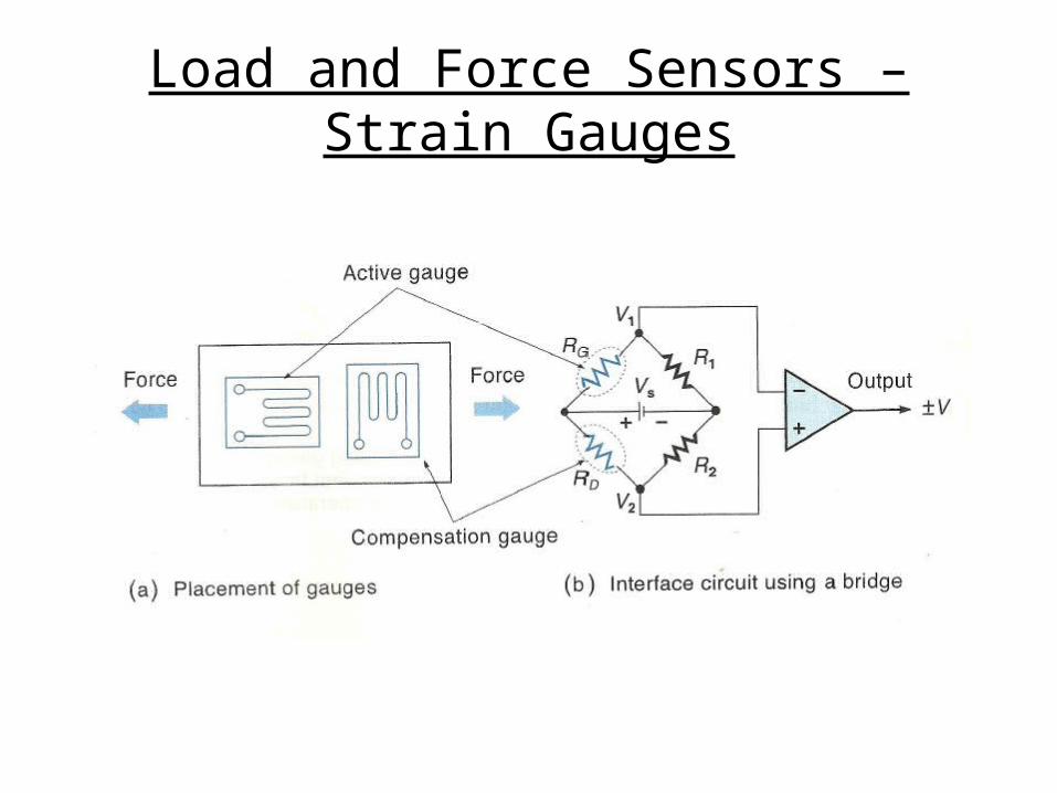
Load and Force Sensors – Strain Gauges
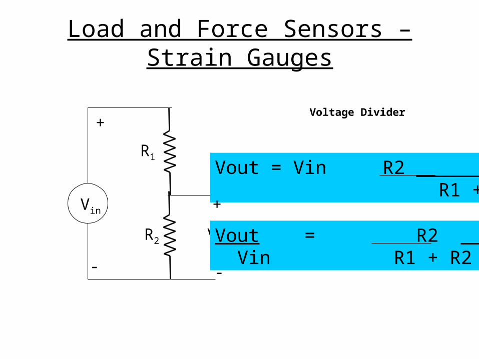
Voltage Divider
R1
Vin
+
-
R2 Vout
Vout = Vin R2 R1 + R2
+
-
Vout = R2 Vin R1 + R2
Load and Force Sensors – Strain Gauges
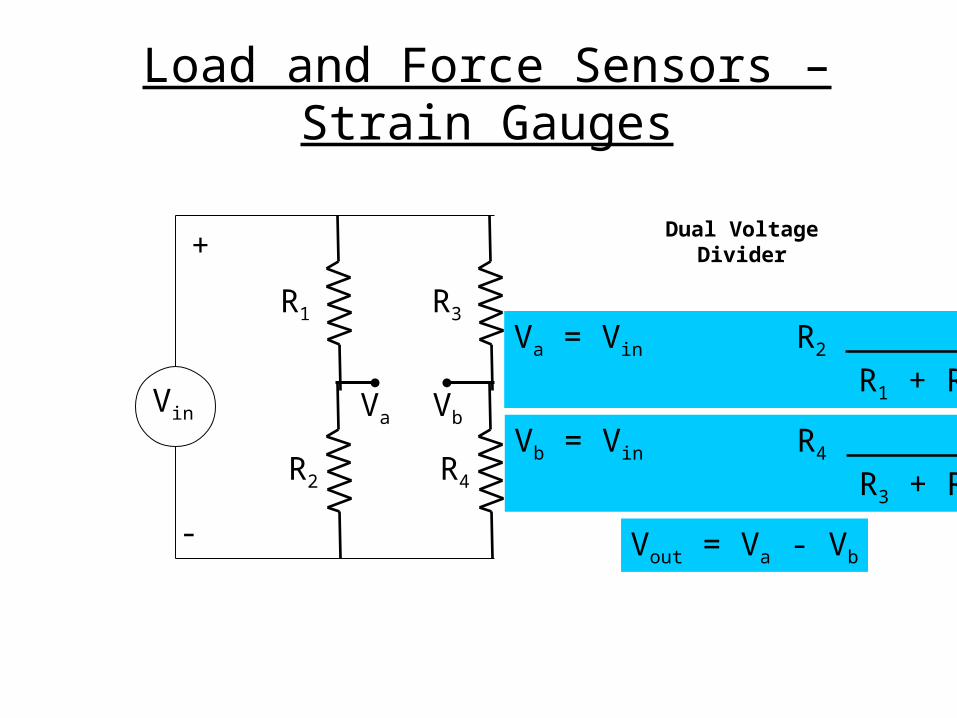
Dual Voltage Divider
R1
Vin
+
-
R2
R3
R4
Va Vb
Va = Vin R2 R1 + R2
Vb = Vin R4 R3 + R4
Vout = Va - Vb
Load and Force Sensors – Strain Gauges
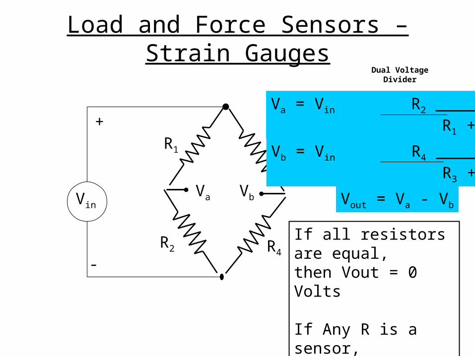
Dual Voltage Divider
R1
Vin
+
-
R2
R3
R4
Va Vb
Va = Vin R2 R1 + R2
Vb = Vin R4 R3 + R4
Vout = Va - Vb
If all resistors are equal,then Vout = 0 Volts
If Any R is a sensor,then Vout is a function of that R value
Load and Force Sensors – Strain Gauges
Load and Force Sensors – Strain Gauges
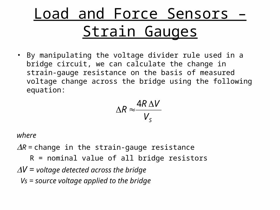
• By manipulating the voltage divider rule used in a bridge circuit, we can calculate the change in strain-gauge resistance on the basis of measured voltage change across the bridge using the following equation:
where
R = change in the strain-gauge resistance
R = nominal value of all bridge resistors
V = voltage detected across the bridge
Vs = source voltage applied to the bridge
SV
VRR
4
Load and Force Sensors – Strain Gauges
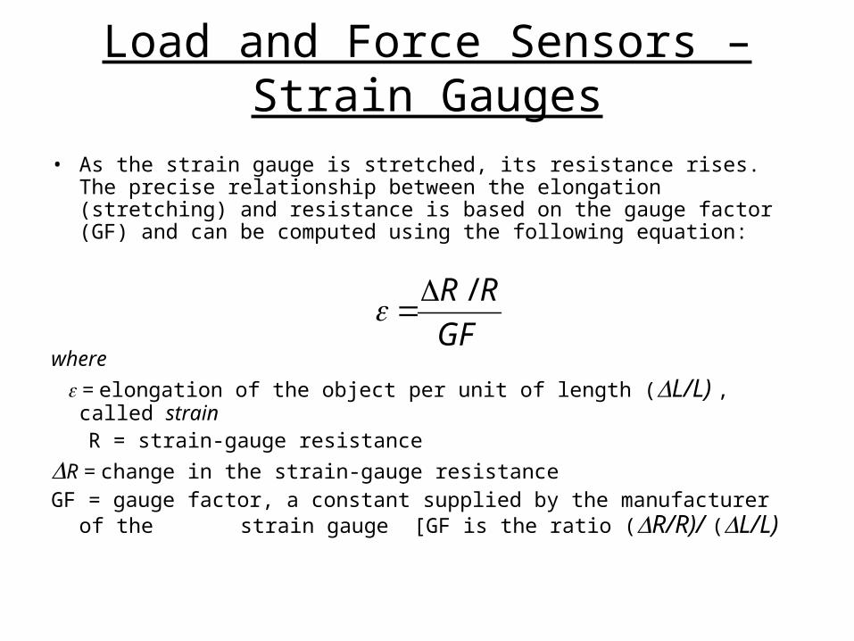
• As the strain gauge is stretched, its resistance rises. The precise relationship between the elongation (stretching) and resistance is based on the gauge factor (GF) and can be computed using the following equation:
where
= elongation of the object per unit of length (L/L) , called strain R = strain-gauge resistance
R = change in the strain-gauge resistanceGF = gauge factor, a constant supplied by the manufacturer of the
strain gauge [GF is the ratio (R/R)/ (L/L)
GF
RR /
Load and Force Sensors – Strain Gauges
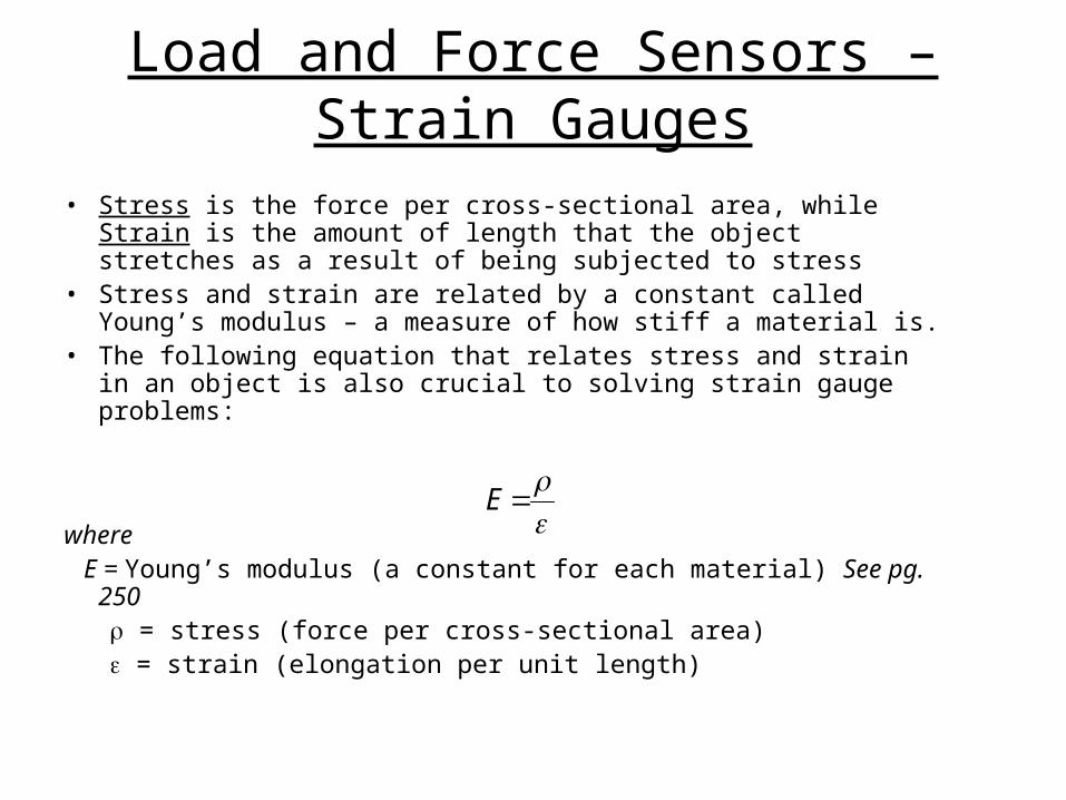
• Stress is the force per cross-sectional area, while Strain is the amount of length that the object stretches as a result of being subjected to stress
• Stress and strain are related by a constant called Young’s modulus – a measure of how stiff a material is.
• The following equation that relates stress and strain in an object is also crucial to solving strain gauge problems:
where E = Young’s modulus (a constant for each material) See pg. 250 = stress (force per cross-sectional area) = strain (elongation per unit length)
E
Load and Force Sensors – Strain Gauges
Load and Force Sensors – Strain Gauges
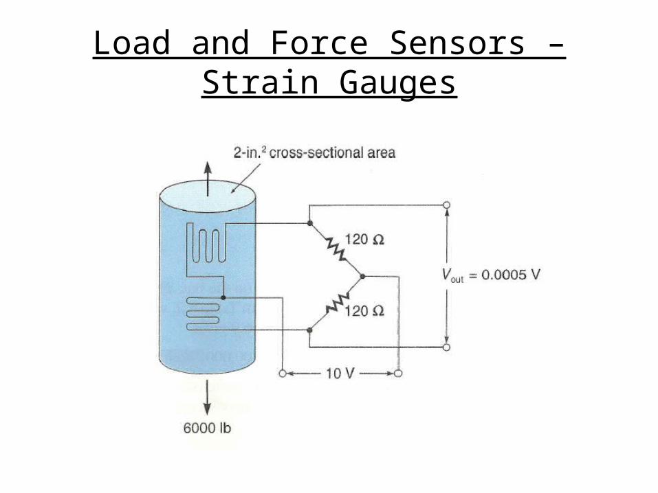
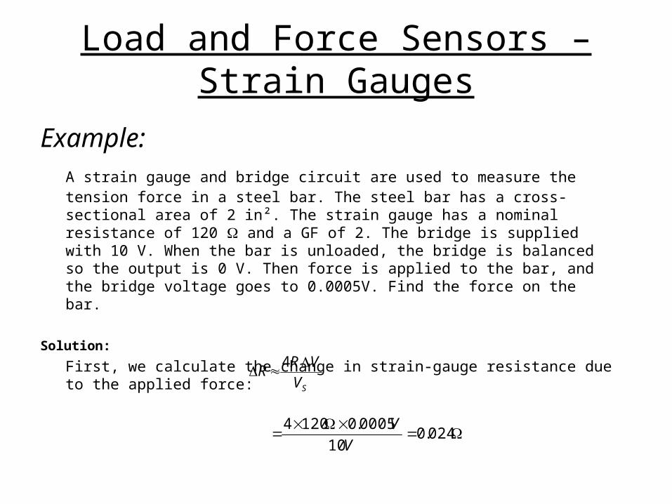
Example:A strain gauge and bridge circuit are used to measure the tension force in a steel bar. The steel bar has a cross-sectional area of 2 in². The strain gauge has a nominal resistance of 120 and a GF of 2. The bridge is supplied with 10 V. When the bar is unloaded, the bridge is balanced so the output is 0 V. Then force is applied to the bar, and the bridge voltage goes to 0.0005V. Find the force on the bar.
Solution:
First, we calculate the change in strain-gauge resistance due to the applied force:
024.010
0005.01204
V
V
SV
VRR
4
Load and Force Sensors – Strain Gauges
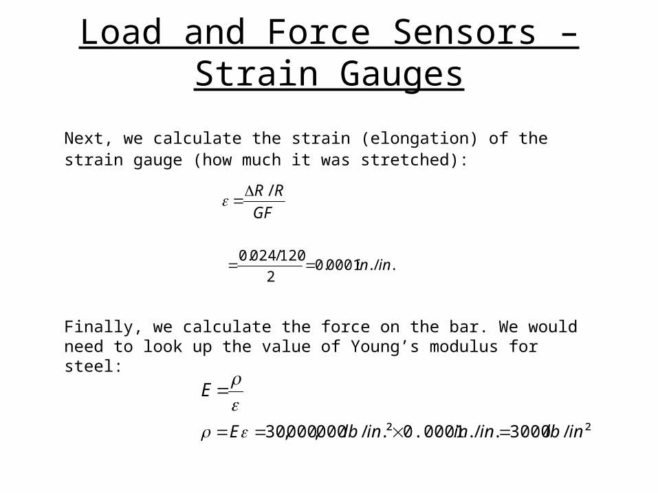
Next, we calculate the strain (elongation) of the strain gauge (how much it was stretched):
Finally, we calculate the force on the bar. We would need to look up the value of Young’s modulus for steel:
GF
RR /
./.0001.02
120/024.0inin
E
²/3000./.0.0001²./000,000,30 inlbinininlbE
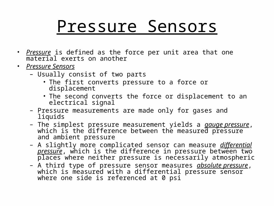
Pressure Sensors• Pressure is defined as the force per unit area that one material exerts on
another• Pressure Sensors
– Usually consist of two parts• The first converts pressure to a force or displacement• The second converts the force or displacement to an electrical
signal– Pressure measurements are made only for gases and liquids– The simplest pressure measurement yields a gauge pressure, which is
the difference between the measured pressure and ambient pressure– A slightly more complicated sensor can measure differential pressure,
which is the difference in pressure between two places where neither pressure is necessarily atmospheric
– A third type of pressure sensor measures absolute pressure, which is measured with a differential pressure sensor where one side is referenced at 0 psi
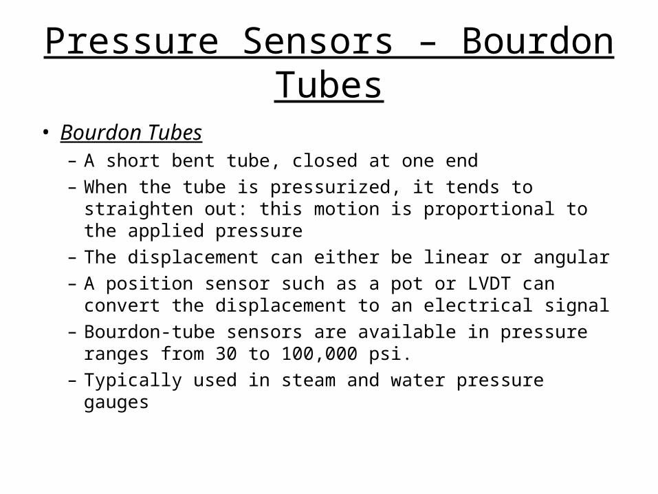
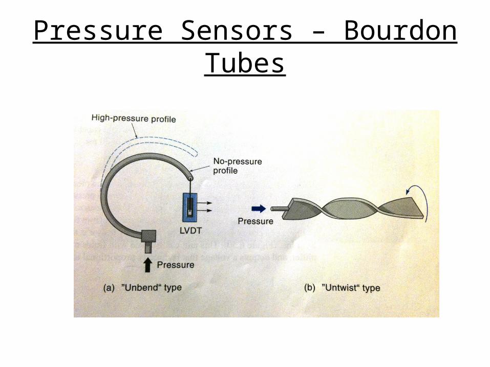
Pressure Sensors – Bourdon Tubes
• Bourdon Tubes– A short bent tube, closed at one end– When the tube is pressurized, it tends to straighten
out: this motion is proportional to the applied pressure– The displacement can either be linear or angular– A position sensor such as a pot or LVDT can convert
the displacement to an electrical signal– Bourdon-tube sensors are available in pressure
ranges from 30 to 100,000 psi.– Typically used in steam and water pressure gauges
Pressure Sensors – Bourdon Tubes
Pressure Sensors – Bellows
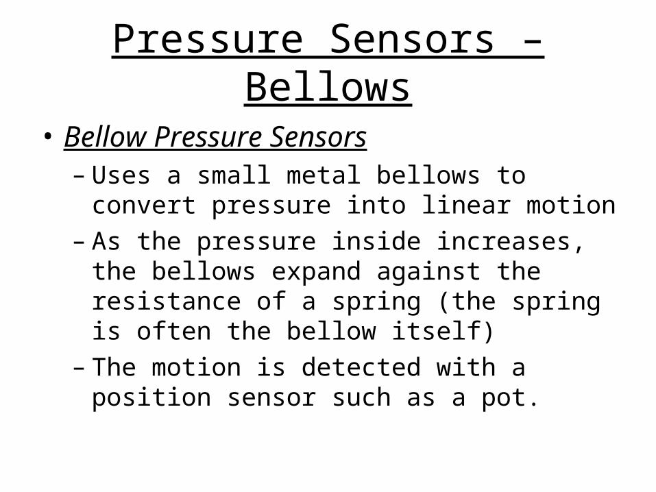
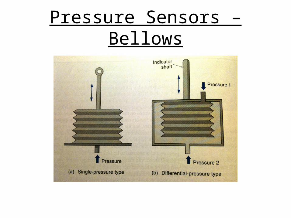
• Bellow Pressure Sensors– Uses a small metal bellows to convert
pressure into linear motion– As the pressure inside increases, the bellows
expand against the resistance of a spring (the spring is often the bellow itself)
– The motion is detected with a position sensor such as a pot.
Pressure Sensors – Bellows
Flow Sensors
• Measure the quantity of fluid material passing by a point in a certain time
• Usually, the material is a gas or liquid and is flowing in a pipe or open-channel.
• Flow transducers come in several types– Those that use differential pressure– Those where the flow spins a mechanical
device
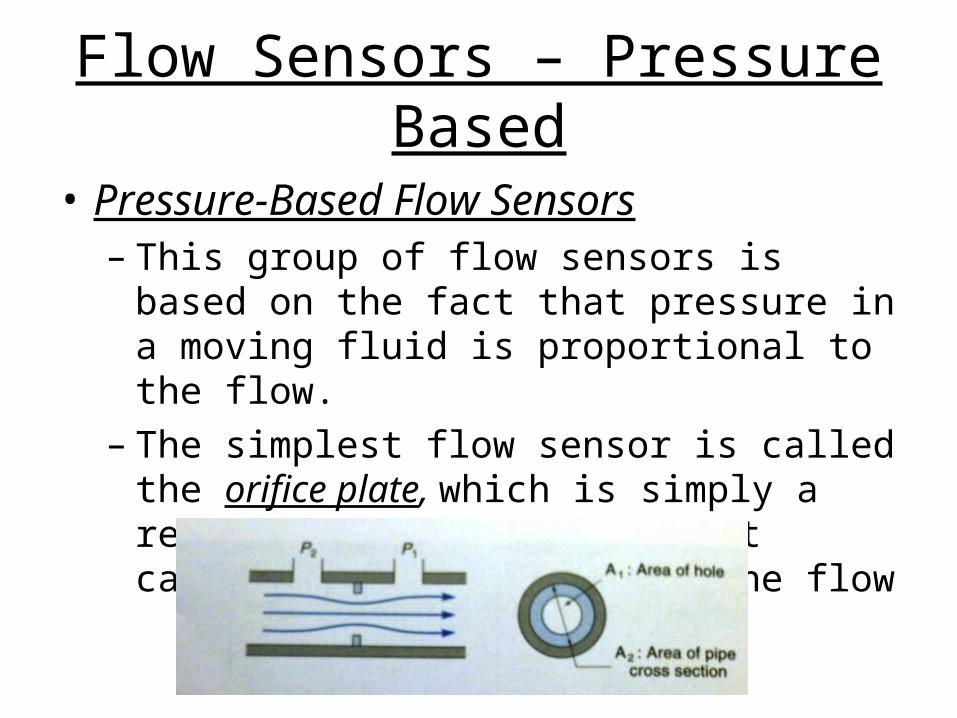
Flow Sensors – Pressure Based
• Pressure-Based Flow Sensors– This group of flow sensors is based on the
fact that pressure in a moving fluid is proportional to the flow.
– The simplest flow sensor is called the orifice plate, which is simply a restriction in the pipe that causes a pressure drop in the flow
Flow Sensors – Pressure Based
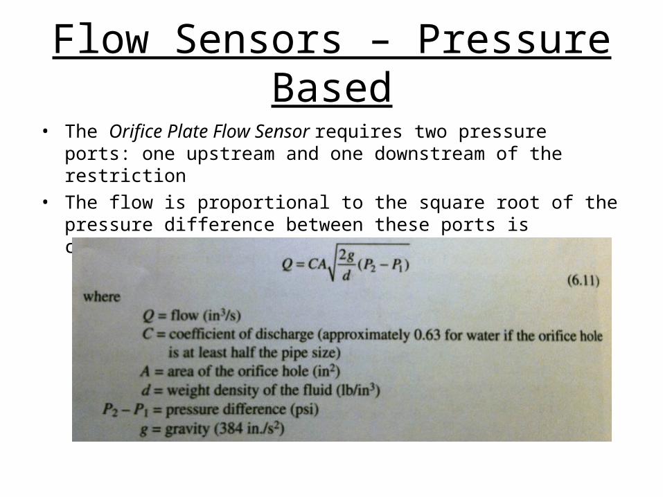
• The Orifice Plate Flow Sensor requires two pressure ports: one upstream and one downstream of the restriction
• The flow is proportional to the square root of the pressure difference between these ports is calculated as follows:
Flow Sensors – Pressure Based
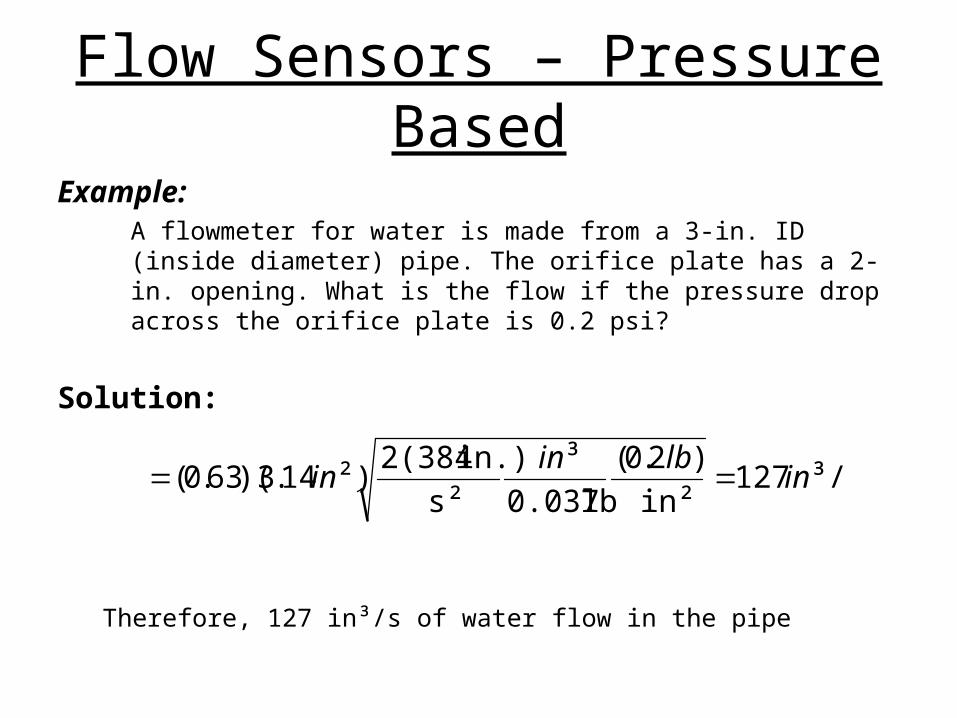
Example:A flowmeter for water is made from a 3-in. ID (inside diameter) pipe. The orifice plate has a 2-in. opening. What is the flow if the pressure drop across the orifice plate is 0.2 psi?
Solution:
Therefore, 127 in³/s of water flow in the pipe
³/s127in²
)2.0(
lb0.037
³
s²
in.)2(384²)14.3)(63.0( in
lbinin
Related Documents