EE 6365 Electrical Engineering Laboratory Manual KINGS COLLEGE OF ENGINEERING, PUNALKULAM Page 1 DEPARTMENT OF MECHANICAL ENGINEERING LABORATORY MANUAL EE 6365 / ELECTRICAL ENGINEERING LABORATORY II YEAR/ THIRD SEM Prepared By Mr.E.Venugopal / AP-II EEE & Mr.P.Narasimman / AP-II EEE

Welcome message from author
This document is posted to help you gain knowledge. Please leave a comment to let me know what you think about it! Share it to your friends and learn new things together.
Transcript

EE 6365 Electrical Engineering Laboratory Manual
KINGS COLLEGE OF ENGINEERING, PUNALKULAM Page 1
DEPARTMENT OF MECHANICAL ENGINEERING
LABORATORY MANUAL
EE 6365 / ELECTRICAL ENGINEERING LABORATORY
II YEAR/ THIRD SEM
Prepared By
Mr.E.Venugopal / AP-II EEE &
Mr.P.Narasimman / AP-II EEE

EE 6365 Electrical Engineering Laboratory Manual
KINGS COLLEGE OF ENGINEERING, PUNALKULAM Page 2
DEPARTMENT OF MECHANICAL ENGINEERING
EE 6365 ELECTRICAL ENGINEERING LABORATORY MANUAL
NAME :
CLASS :
SEMESTER :
ROLL NUMBER :
REGISTER NUMBER :

EE 6365 Electrical Engineering Laboratory Manual
KINGS COLLEGE OF ENGINEERING, PUNALKULAM Page 3
DEPARTMENT OF ELECTRICAL AND ELECTRONICS ENGINEERING
ACADEMIC YEAR 2014-2015 (ODD SEMESTER)
SYLLABUS
1. Study of DC & AC Starters
CYCLE-1
2. Load test on DC Shunt motor 3. Load test on DC Series motor 4. O.C.C & Load characteristics of DC Shunt generator 5. O.C.C & Load characteristics of DC Series generator 6. Speed control of DC shunt motor (Armature, Field control) 7. Load test on single phase transformer
CYCLE-2
8. O.C & S.C Test on a single phase transformer 9. Regulation of an alternator by EMF & MMF methods. 10. V curves and inverted V curves of synchronous Motor 11. Load test on three phase squirrel cage Induction motor 12. Speed control of three phase slip ring Induction Motor 13. Load test on single phase Induction Motor.
CONTENT BEYOND SYLLABUS
1. O.C.C & Load characteristics of separately excited DC Shunt generator.
SIGN OF STAFF INCHARGE SIGN OF HOD

EE 6365 Electrical Engineering Laboratory Manual
KINGS COLLEGE OF ENGINEERING, PUNALKULAM Page 4
INDEX
S. No. Date Title of Experiment
Page No.
Mark (10)
Sign
1
2
3
4
5
6
7
8
9
10
11
12
13
CONTENT BEYOND SYLLABUS
14

EE 6365 Electrical Engineering Laboratory Manual
KINGS COLLEGE OF ENGINEERING, PUNALKULAM Page 5
Ex. No : STUDY OF DC MOTOR AND INDUCTION MOTOR STARTERS
Date :
AIM:
To study the DC and AC motor starters.
APPARATUS / INSTRUMENTS REQUIRED:
Necessity of Starters
When a supply voltage is applied to a motor the starting current is high because of very low armature resistance. The starting current is much more than the full load current The excessive current will blow out fuses and may damage the brushes etc To avoid this excessive starting current, a resistance is inserted in series with the armature and is gradually cut out as the motor gains speed and develop the back e.m.f. which regulates the speed. Equipments used for protection of dc motors, for the following reasons:
protect motor against damage due to short circuits in equipment
protect motor against damage from long-term overloads
protect motor against damage from excessive starting currents
provide a convenient manner in which to control the operating speed of motor Three point starter
The internal wiring for such a starter is shown if the figure. The three terminals of the starting box are marked as L, F, A. One line is directly connected to one armature terminal and one field terminal which are tied together. The other line is connected to point L which is further connected to the starting arm, through the over –current (or over load) release M.
To start the motor, the main switch is first closed and then the starting arm is slowly moved to the right. As soon as the arm makes contact with stud no.1, the field circuit is directly connected across the line and at the same time full starting resistance RS is placed in series with the armature. The starting current drawn by the armature=V/(RA+RS) where RS is the starting resistance. As the arm is further moved, the starting resistance is gradually cut out till, when the arm reaches the running position, the resistance is all cut out. The arm moved over the various studs against a strong spring which tends to restore it to OFF position. There is a soft iron piece S attached and held by an electromagnet E energized by the shunt current. It is variously known as “HOLD-ON” coil, LOW-VOLTAGE (or NO-VOLTAGE) realize.
It will be seen that as the arm is moved from stud 1 to the last stud, the field current has to travel back through that portion of the starting resistance that has been cut out of the armature circuit. This results in slight decrease of shunt current. But as the value of starting resistance is very small as compared to shunt field resistance, this slight decrease in I is negligible.

EE 6365 Electrical Engineering Laboratory Manual
KINGS COLLEGE OF ENGINEERING, PUNALKULAM Page 6
The normal function of HOLD-ON coil is to hold the arm in the full running position when the motor is in running position. But, in case of failure or disconnecting of the supply or break in the field circuit, it is de-energized thereby releasing the arm which is pulled back by the spring to the OFF position. This prevents the stationary armature from being put across the lines again when the supply when the supply is restored after temporary shutdown. This would have happened if the arm were left in the full null position. One great advantage of connecting the HOLD-ON coil in series with the shunt field is that, should the field circuit become open, the starting arm immediately springs back to the OFF position thereby preventing the motor from running away.
The over-current release consists of electromagnet connected in the supply line. If the motor becomes over-loaded beyond a certain predetermined value, then D is lifted and short-circuits the electromagnet. Hence, the arm is released and returns to OFF position.
The form of over-load protection described above is becoming obsolete, because it cannot be made either as accurate or as reliable as a separate well-designed circuit breaker with a suitable time element attachment. Many a times a separate magnetic contractor with an overload relay is also used.
Often the motors are protected by thermal overload relay in which a bimetallic strip is heated by the motor is itself heating up. Above a certain temperature, this relay trips and opens the line contractor thereby isolating the motor from the supply.
It is desired to control the speed the motor in addition, and then a field rheostat is connected in the field circuit as shown in the figure. The motor speed can be increased by weakening the flux
(N1/) obviously, there is a limit to the speed increase obtained in this way, although speed ranges of three or four are possible. If too much resistance is ‘cut-in’ by the field rheostat, then field current is reduced very much so that it is unable to create enough electromagnetic pull to overcome the spring tension. Hence, the arm is pulled back to OFF position. It is this undesirable feature of a three-point starter which it makes it unsuitable for use with variable speed motors. This has resulted in wide range application of four point starters.

EE 6365 Electrical Engineering Laboratory Manual
KINGS COLLEGE OF ENGINEERING, PUNALKULAM Page 7
Four point starter
Such a starter with its internal winding is shown connected to a long –shunt compound motor in fig4.when compared to the three-point starter, it will be noticed that one important change has been made i.e., the HOLD-ON coil has been taken out of the shunt field and has been connected directly across the line through a protecting resistance as shown. When the arm touches stud no.1, then the line current divides into three parts
One part passes through starting resistance Rs, series field and motor armature
The second part passes through the shunt field and its field rheostat Rh
The third part passed through the HOLD-ON coil and current protecting resistance R. It should be particularly noted that with this arrangement any change of current in the shunt
field circuit does not at all affect the current passing through the HOLD-ON coil because the two circuits are independent of each other. It means that the electromagnetic pull exerted by the HOLD-ON coil will always be sufficient and will prevent the spring from restoring the starting arm to OFF position no matter how the field rheostat or regulator is adjusted.
NECESSITY OF STARTER IN INDUCTION MOTOR:
In a three phase induction motor, the magnitude of an induced e.m.f. in the rotor circuit depends on the slip of the induction motor. This induced e.m.f. effectively decides the magnitude of the rotor current. The rotor current in the running condition is given by, But at start, the speed of the motor is zero and slip is at its maximum i.e. unity. So magnitude of rotor induced e.m.f. is very large at start. As rotor conductors are short circuited, the large induced e.m.f. circulates very high current through rotor at start. The condition is exactly similar to a transformer with short circuited secondary. Such a transformer when excited by a rated voltage circulates very high current through short circuited secondary. As secondary current is large, the primary also draws very high current from the supply. Similarly in a three phase induction motor, when rotor current is high,
EE 6365 Electrical Engineering Laboratory Manual
KINGS COLLEGE OF ENGINEERING, PUNALKULAM Page 8
consequently the stator draws a very high current from the supply. This current can be of the order of 5 to 8 times the full load current, at start. Due to such heavy inrush of current at start there is possibility if damage of the motor winding. Similarly such sudden inrush of current causes large line voltage drop. Thus other appliances connected to the same line may be subjected to voltage spikes which may affect their working. To avoid such effects, it is necessary to limit the current drawn by the motor at start. The starter is a device which is basically used to limit high starting current by supplying reduced voltage to the motor at the time of starting. Such a reduced voltage is applied only for short period and once rotor gets accelerated, full normal rated Not only the starter limits the starting current but also provides the protection to the induction motor against overt loading and low voltage situations. The protection against single phasing is also provided by the starter. The withstand starting currents hence such motors can be started directly on line. But such motors also need overload, single phasing and low voltage protection which is provided by a starter.
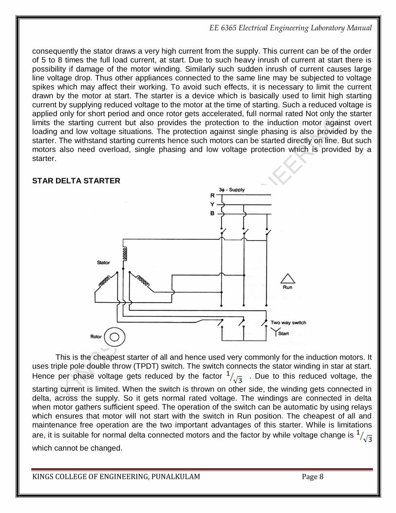
STAR DELTA STARTER
This is the cheapest starter of all and hence used very commonly for the induction motors. It uses triple pole double throw (TPDT) switch. The switch connects the stator winding in star at start.
Hence per phase voltage gets reduced by the factor . Due to this reduced voltage, the
starting current is limited. When the switch is thrown on other side, the winding gets connected in delta, across the supply. So it gets normal rated voltage. The windings are connected in delta when motor gathers sufficient speed. The operation of the switch can be automatic by using relays which ensures that motor will not start with the switch in Run position. The cheapest of all and maintenance free operation are the two important advantages of this starter. While is limitations
are, it is suitable for normal delta connected motors and the factor by while voltage change is
which cannot be changed.

EE 6365 Electrical Engineering Laboratory Manual
KINGS COLLEGE OF ENGINEERING, PUNALKULAM Page 9
DOL STARTER
In case of small capacity motors having rating less than 5 h.p., the starting current is not very high and such motors can withstand such starting current without any starter. Thus there is no need to reduce applied voltage, to control the starting current. Such motors use a type of starter which is used to connect stator directly lines without any reduction in voltage. Hence the starter is known as direct on line starter. Through this starter does not reduce the applied voltage, it is used because it protects the motor from various severe abnormal conditions like over voltage, single phasing etc. The NO contact is normally open and NC is normally closed. At start, NO is pushed for fraction of second due to which coil gets energized and attracts the contactor.
So stator directly gets supply. The additional contact provided that as long as supply in ON, the coil gets supply and keeps contactor in ON position. When NC is pressed, the coil circuit gets opened due to which coil gets de-energized and motor gets switched OFF from the supply. Under over load condition, current drawn by the motor increase due to which there is an excessive heat produced, which increase temperature beyond limit Thermal relays gets opened due to high temperature, protecting the motor from overload conditions.

EE 6365 Electrical Engineering Laboratory Manual
KINGS COLLEGE OF ENGINEERING, PUNALKULAM Page 10
AUTOTRANSFORMER STARTER:
A three phase star connected autotransformer can be used to reduce the voltage applied to the stator. Such a starter is called an autotransformer starter. It consists of a suitable change over switch. When the switch is in the start position, the stator winding is supplied with reduced voltage. This can be controlled by tapping provide with autotransformer. When motor gathers 80% of the normal speed, the change over switch is thrown into run position. Due to this, rated voltage gets applied to stator winding. The motor starts rotating with normal speed. Changing of switch is done automatically by using relays. The power loss is much less in this type of starting. It can be used for both star and delta connected motors. But it is expensive than stator resistance starter. RESULT:
Thus the DC and AC motor starters were studied. VIVA QUESTIONS: What is a starter? What is the necessity of starter? What are the types of dc and ac starters? What is the main disadvantage of 3 point starter? What id DOL starter? What are the advantages of using starters?

EE 6365 Electrical Engineering Laboratory Manual
KINGS COLLEGE OF ENGINEERING, PUNALKULAM Page 11
Ex. No : LOAD TEST ON DC SHUNT MOTOR
Date :
AIM:
To conduct the load test on a given DC shunt motor and to draw its performance curves.
APPARATUS REQUIRED:
THEORY:
It is a direct method to determine the efficiency. The motor is loaded directly by applying
brake to a water cooled pulley mounted on the motor shaft. This test is performed in small
machines because in case of large motors it is difficult to dissipate the heat. This method is used
for determining internal losses. In this motor, since the field is connected in parallel with the supply,
the field current and hence the flux are very nearly constant. DC shunt motors are used where the
speed has to remain constant with load. As flux remains almost constant T Ia..
FORMULAE USED:
Torque
where R-radius of brake drum in m t- thickness of the belt in m S1,S2-spring balance reading in Kg
where VL-load voltage in V
IL-load current in A
S.No Name of the Apparatus Type Range Quantity
1 Ammeter MC (0-20)A 1
2 Ammeter MC (0-2)A 1
3 Voltmeter MC (0-300)V 1
4 Rheostat Wire
wound 300 ,2A 1
5 Tachometer Digital - 1
6 Connecting wires - - Req

EE 6365 Electrical Engineering Laboratory Manual
KINGS COLLEGE OF ENGINEERING, PUNALKULAM Page 12

EE 6365 Electrical Engineering Laboratory Manual
KINGS COLLEGE OF ENGINEERING, PUNALKULAM Page 13
where N-Speed of the armature in rpm T-Torque in Nm
Percentage efficiency = (Output power/Input power) x100 PRECAUTIONS: The motor field rheostat should be kept at minimum resistance position. At the time of starting the motor should be in no load condition. The motor should be run in anticlockwise direction.
PROCEDURE:
1. Connections are given as per the circuit diagram 2. Using the three point starter the motor is started to run at the rated speed by adjusting the
field rheostat if necessary 3. The meter readings are noted at no load condition 4. By using the break drum with spring balance arrangement the motor is loaded and the
corresponding readings are noted upto the rated current 5. After the observation of all the readings the load is released gradually 6. The motor is switched off.
TABULATION:
S.No
Load
Voltage
VL (V)
Load
Current
IL (I)
Speed
N
(rpm)
Spring Balance Reading
(kg) Torque T
(Nm)
Input
Power
Pi (W)
output
Power
Po (W)
Efficiency
ŋ (%)
S1 S2 S1~S2

EE 6365 Electrical Engineering Laboratory Manual
KINGS COLLEGE OF ENGINEERING, PUNALKULAM Page 14
CALCULATIONS:
EE 6365 Electrical Engineering Laboratory Manual
KINGS COLLEGE OF ENGINEERING, PUNALKULAM Page 15
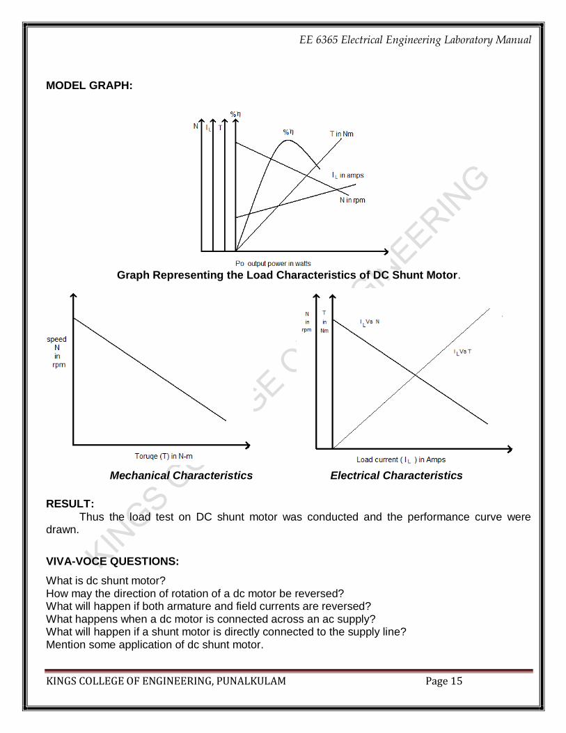
MODEL GRAPH:
Graph Representing the Load Characteristics of DC Shunt Motor.
Mechanical Characteristics Electrical Characteristics
RESULT:
Thus the load test on DC shunt motor was conducted and the performance curve were drawn.
VIVA-VOCE QUESTIONS:
What is dc shunt motor? How may the direction of rotation of a dc motor be reversed? What will happen if both armature and field currents are reversed? What happens when a dc motor is connected across an ac supply? What will happen if a shunt motor is directly connected to the supply line? Mention some application of dc shunt motor.

EE 6365 Electrical Engineering Laboratory Manual
KINGS COLLEGE OF ENGINEERING, PUNALKULAM Page 16
Ex. No : LOAD TEST ON DC SERIES MOTOR
Date :
AIM:
To conduct the load test on a given DC series motor and to draw its performance curves.
APPARATUS REQUIRED: THEORY:
It is a direct method to determine the efficiency. The motor is loaded directly by applying
brake to a water cooled pulley mounted on the motor shaft. This test is performed in small
machines because in case of large motors it is difficult to dissipate the heat. In this motor, since
the field is connected in series with the supply, the field current and armature current is same. DC
series motors are used where high starting torque is required.
FORMULAE USED:
Torque
where R-radius of brake drum in m t- thickness of the belt in m S1,S2-spring balance reading in Kg
where VL-load voltage in V
IL-load current in A
S.No Name of the Apparatus Type Range Quantity
1 Ammeter MC (0-20)A 1
2 Voltmeter MC (0-300)V 1
3 Rheostat Wire
wound 300 ,2A 1
4 Tachometer Digital - 1
5 Connecting wires - - Req

EE 6365 Electrical Engineering Laboratory Manual
KINGS COLLEGE OF ENGINEERING, PUNALKULAM Page 17

EE 6365 Electrical Engineering Laboratory Manual
KINGS COLLEGE OF ENGINEERING, PUNALKULAM Page 18
where N-Speed of the armature in rpm
T-Torque in Nm Percentage efficiency = (Output power/Input power) x100 PRECAUTIONS:
At the time of starting the motor should be in load condition. The motor should be run in anticlockwise direction.
PROCEDURE:
1. Connections are given as per the circuit diagram 2. Using the two point starter the motor is started 3. The meter readings are noted at the load condition 4. By using the break drum with spring balance arrangement the motor is loaded and the
corresponding readings are noted upto the rated current 5. After the observation of all the readings the load is released gradually but not fully. 6. The motor is switched off.
TABULATION:
S.No
Load
Voltage
VL (V)
Load
Current
IL (I)
Speed
N
(rpm)
Spring Balance Reading
(kg) Torque T
(Nm)
Input
Power
Pi (W)
output
Power
Po (W)
Efficiency
ŋ (%)
S1 S2 S1~S2

EE 6365 Electrical Engineering Laboratory Manual
KINGS COLLEGE OF ENGINEERING, PUNALKULAM Page 19
CALCULATIONS:

EE 6365 Electrical Engineering Laboratory Manual
KINGS COLLEGE OF ENGINEERING, PUNALKULAM Page 20
MODEL GRAPH:
Graph Representing the Load Characteristics of DC Shunt Motor.
Mechanical Characteristics Electrical Characteristics
RESULT:
Thus the load test on DC series motor was conducted and the performance curve were drawn.
VIVA-VOCE QUESTIONS:
What is dc series motor? Mention some application of dc series motor. Why the DC series motor should be started with load?
EE 6365 Electrical Engineering Laboratory Manual
KINGS COLLEGE OF ENGINEERING, PUNALKULAM Page 21
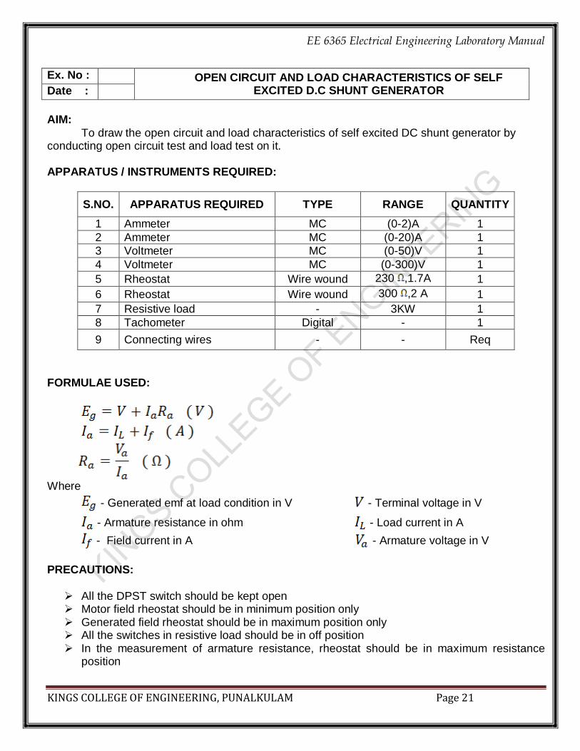
Ex. No : OPEN CIRCUIT AND LOAD CHARACTERISTICS OF SELF EXCITED D.C SHUNT GENERATOR Date :
AIM:
To draw the open circuit and load characteristics of self excited DC shunt generator by conducting open circuit test and load test on it.
APPARATUS / INSTRUMENTS REQUIRED:
S.NO. APPARATUS REQUIRED TYPE RANGE QUANTITY
1 Ammeter MC (0-2)A 1
2 Ammeter MC (0-20)A 1
3 Voltmeter MC (0-50)V 1
4 Voltmeter MC (0-300)V 1
5 Rheostat Wire wound 230 ,1.7A 1
6 Rheostat Wire wound 300 ,2 A 1
7 Resistive load - 3KW 1
8 Tachometer Digital - 1
9 Connecting wires - - Req
FORMULAE USED:
Where
- Generated emf at load condition in V - Terminal voltage in V
- Armature resistance in ohm - Load current in A
- Field current in A - Armature voltage in V
PRECAUTIONS:
All the DPST switch should be kept open Motor field rheostat should be in minimum position only Generated field rheostat should be in maximum position only All the switches in resistive load should be in off position In the measurement of armature resistance, rheostat should be in maximum resistance
position

EE 6365 Electrical Engineering Laboratory Manual
KINGS COLLEGE OF ENGINEERING, PUNALKULAM Page 22

EE 6365 Electrical Engineering Laboratory Manual
KINGS COLLEGE OF ENGINEERING, PUNALKULAM Page 23
PROCEDURE: A.OPEN CIRCUIT TEST:
1. Make the connection as per the circuit diagram. 2. Close the DPST switch 3. Start the motor using three point starter. 4. By adjusting motor field rheostat set the motor-generator to its rated speed 5. Note down the generator voltage indicated by the voltmeter in table 6. Adjust the generator field rheostat and note down the field current (If) & generator emf (Eo)
indicated by the ammeter and voltmeter respectively 7. Repeat the same procedure until the voltmeter reads rated voltage of DC Generator.
B. LOAD TEST:
1. Now close the DPST switch. 2. Adjust the resistive load and note down the corresponding load current IL and terminal voltage
indicated by the ammeter and voltmeter respectively in table. 3. Repeat the same procedure till the load current reaches the rated load current. TABULATION:
Tabulation for Open Circuit Test of Self Excited DC shunt Generator
S.No. Field current If in A Generated emf Eg in V
Tabulation for Load test of Self Excited DC Shunt Generator
S.No. Load current
(IL in A) Terminal voltage
(Vt in V) Armature current
(Ia in A)
Generated voltage (Eg in V)

EE 6365 Electrical Engineering Laboratory Manual
KINGS COLLEGE OF ENGINEERING, PUNALKULAM Page 24
CALCULATIONS:

EE 6365 Electrical Engineering Laboratory Manual
KINGS COLLEGE OF ENGINEERING, PUNALKULAM Page 25
MODEL GRAPH:
Graph Representing the Magnetization or Open Circuit Characteristics of Self Excited DC Shunt Generator.
Graph Representing the Load Characteristics of Self Excited DC Shunt Generator.
RESULT: Thus the open circuit and load test on Self Excited DC Shunt Generator was conducted and the magnetization and load characteristics were drawn.
VIVA-VOCE QUESTIONS:
What is separately excited? What is magnetization? Why the motor field rheostat is in minimum position? Why the generator field rheostat is in maximum position? What is meant by buildup of a generator?
EE 6365 Electrical Engineering Laboratory Manual
KINGS COLLEGE OF ENGINEERING, PUNALKULAM Page 26
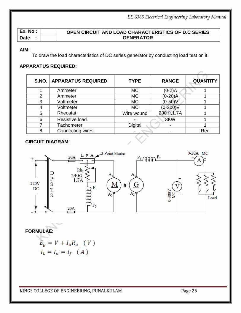
Ex. No : OPEN CIRCUIT AND LOAD CHARACTERISTICS OF D.C SERIES GENERATOR Date :
AIM:
To draw the load characteristics of DC series generator by conducting load test on it.
APPARATUS REQUIRED:
S.NO. APPARATUS REQUIRED TYPE RANGE QUANTITY
1 Ammeter MC (0-2)A 1
2 Ammeter MC (0-20)A 1
3 Voltmeter MC (0-50)V 1
4 Voltmeter MC (0-300)V 1
5 Rheostat Wire wound 230 ,1.7A 1
6 Resistive load - 3KW 1
7 Tachometer Digital - 1
8 Connecting wires - - Req
CIRCUIT DIAGRAM:
FORMULAE:

EE 6365 Electrical Engineering Laboratory Manual
KINGS COLLEGE OF ENGINEERING, PUNALKULAM Page 27
Where,
- Generated emf at load condition in V - Terminal voltage in V
- Armature resistance in ohm - Load current in A
- Field current in A - Armature voltage in V
PRECAUTIONS:
All the DPST switch should be kept open Motor field rheostat should be in minimum position only All the switches in resistive load should be in off position In the measurement of armature resistance, rheostat should be in maximum resistance
position. PROCEDURE: LOAD TEST:
1. Make the connection as per the circuit diagram 2. Close the DPST switch1 3. Start the motor using three point starter. 4. By adjusting motor field rheostat set the motor-generator to its rated speed 5. Now close the DPST switch2. 6. Adjust the resistive load and note down the corresponding load current IL and terminal voltage indicated by the ammeter and voltmeter respectively. 7. Repeat the same procedure till the load current reaches the rated load current Tabulation for Load test of Self Excited DC Shunt Generator
S.No. Load current
(IL in A)
Terminal voltage (Vt in V)
Generated voltage (Eg in V)

EE 6365 Electrical Engineering Laboratory Manual
KINGS COLLEGE OF ENGINEERING, PUNALKULAM Page 28
MODEL GRAPH:
.
RESULT:
Thus the load test was conducted and the performance curves were drawn.

EE 6365 Electrical Engineering Laboratory Manual
KINGS COLLEGE OF ENGINEERING, PUNALKULAM Page 29
Ex. No : SPEED CONTROL OF DC SHUNT MOTOR
Date :
AIM:
To conduct an experiment to control the speeds of the given DC shunt motor by field and armature control method also to draw its characteristic curves.
APPARATUS REQUIRED:
S.NO Name of the Apparatus Type Range Quantity
1. Ammeter MC (0-2A) 1
2 Ammeter MC (0-10A) 1
3. Voltmeter MC (0-300V) 1
4. Rheostat Wire wound (300Ω, 2 A) 1
5. Rheostat Wire wound (50Ω,5A) 1
6. Tachometer Digital - 1
7. Connecting wires - - Req
THEORY:
The speed of the DC motor is given by N=V-IaRa(A/PZ).Hence the speed of the motor can be varied by varying either the resistance in the armature circuit (Rheostat control), or flux (Flux control ) or applied voltage. By increasing the controller resistance, the potential drop across the armature is decreased. Hence the motor speed also decreases. This method of speed control is applicable only for speed less than no load or rated or base speed. By decreasing the field current by means of external resistance, the flux decreases. As a result the speed of the motor gets increased. This method is applicable for obtaining speed above rated speed.
PRECAUTIONS:
The motor field rheostat should be kept at minimum resistance position. The motor armature rheostat should be kept at maximum resistance position. The motor should be in no load condition throughout the experiment. The motor should be run in anticlockwise direction.
PROCEDURE: FIELD CONTROL METHOD (FLUX CONTROL METHOD)
1. Connections are given as per circuit diagram. 2. Using the three point starter the motor is started to run. 3. The armature rheostat is adjusted to run the motor at rated speed by means of applying the
rated voltage. 4. The field rheostat is varied gradually and the corresponding field current and speed are noted
up to 120% of the rated speed by keeping the armature current as constant.

EE 6365 Electrical Engineering Laboratory Manual
KINGS COLLEGE OF ENGINEERING, PUNALKULAM Page 30

EE 6365 Electrical Engineering Laboratory Manual
KINGS COLLEGE OF ENGINEERING, PUNALKULAM Page 31
5. The motor is switched off using the DPST switch after bringing all the rheostats to their initial position. ARMATURE CONTROL METHOD (VOLTAGE CONTROL METHOD)
1. Connections are given as per circuit diagram 2. Using the three point starter the motor is started to run. 3. The armature rheostat is adjusted to run the motor at rated speed by means of applying the
rated voltage. 4. The armature rheostat is varied gradually and the corresponding armature voltage and speed
are noted up to the rated voltage. 5. The motor is switched off using the DPST (Double pole single throw) switch after bringing all the
rheostats to their initial position. CALCULATIONS:
Tabulation for Speed Control of DC Shunt Motor
S.NO
Armature Control Method Field Control Method
Field Current (If) = A Armature Voltage (Va)= V
Armature Voltage (Va) V
Speed (N) Rmp
Field Current
(If) A Speed (N)
Rmp

EE 6365 Electrical Engineering Laboratory Manual
KINGS COLLEGE OF ENGINEERING, PUNALKULAM Page 32
MODEL GRAPH:
Armature Control Method Field Control Method
RESULT:
Thus the speed of the DC shunt motor is controlled by conducting field control and armature control method. VIVA-VOCE QUESTIONS:
What are the types of speed control techniques in dc shunt motor? Application of speed control technique in dc shunt motor. What is flux control technique? What happens when the load is increased in shunt motor? Why a dc shunt motor is found suitable to drive fans?

EE 6365 Electrical Engineering Laboratory Manual
KINGS COLLEGE OF ENGINEERING, PUNALKULAM Page 33
Ex. No : LOAD TEST ON SINGLE PHASE TRANSFORMER
Date :
AIM:
To conduct the load test on a given single phase transformer and to draw its performance curves.
APPARATUS / INSTRUMENTS REQUIRED:
S.No Name of The Apparatus Type Range Quantity
1. Ammeter MI (0-10) A 2
2. Voltmeter MI (0-300) V 2
3. Wattmeter UPF (300V, 10A) 2
4. Auto Transformer 1 230/(0-270V) 1
5. Resistive load - 3kW 1
6. Connecting wires - - Req
THEORY:
It is a direct load test. A resistive load arrangement may be used. The output equation given
by VSY ISY cos in W. The purpose of the load test may be either to study the behavior of
efficiency and regulation of the transformer.
FORMULAE USED: Where,
VNL = No load voltage in V. VLOAD = Load voltage in V.

EE 6365 Electrical Engineering Laboratory Manual
KINGS COLLEGE OF ENGINEERING, PUNALKULAM Page 34

EE 6365 Electrical Engineering Laboratory Manual
KINGS COLLEGE OF ENGINEERING, PUNALKULAM Page 35
PRECAUTIONS: At the time of starting transformer should be at no load condition. High voltage and low voltage sides of the transformer should be properly used as primary or
secondary respective experiments. PROCEDURE:
1. The circuit diagram for load test on single-phase transformer is shown in figure. 2. Connections are given as per the circuit diagram. 3. The DPST Switch on the primary side is closed and the DPST Switch on the Secondary side is
opened. 4. The Autotransformer is adjusted to energize the transformer with rated primary voltage. 5. The Voltmeter and Ammeter readings are noted and tabulated at no load condition. 6. The DPST switch on the secondary side is closed. 7. The transformer is loaded up to 130% of the Rated load, corresponding Ammeter, Voltmeter and
Wattmeter readings are noted and tabulated. 8. After the observation of all the readings the load is released gradually to its initial position. 9. The Autotransformer is brought to its initial position. 10. The Supply is switched off.
TABULATION:
Tabulation for Load Test of Single Phase Transformer
S.N
o
Pri
Vo
lta
ge
(V
Pri)
V
Pri
Curr
en
t (I
Pri)
A
Se
c V
olta
ge
(V
Sec)
V
Se
c C
urr
en
t (I
Sec)
A Input
Wattmeter readings
(W)
Output Wattmeter readings
(W)
Inp
ut
Po
wer
W
Ou
tpu
t P
ow
er
W
% %
Reg
Obs Act Obs Act

EE 6365 Electrical Engineering Laboratory Manual
KINGS COLLEGE OF ENGINEERING, PUNALKULAM Page 36
CALCULATIONS: MODEL GRAPH:
RESULT:
Thus the load test on single-phase transformer is conducted and performance characteristics curves
are drawn.
VIVA-VOCE QUESTIONS:
What is a transformer?
What is the principle of operation of transformer?
What is transformation ratio?
What is an ideal transformer?
What is regulation?

EE 6365 Electrical Engineering Laboratory Manual
KINGS COLLEGE OF ENGINEERING, PUNALKULAM Page 37
Ex. No : OPEN CIRCUIT AND SHORT CIRCUIT TEST ON SINGLE PHASE TRANSFORMER Date :
AIM:
To predetermine the efficiency and regulation of a given single Phase transformer by conducting the
open circuit test and short circuit test also to draw its Equivalent circuit.
APPARATUS REQUIRED:
S.no Name of the apparatus Type Range Quantity
1 Ammeter MI (0-2) A 1
2 Ammeter MI (0-10) A 1
3 Ammeter MI (0-20) A 1
4 Voltmeter MI (0-150) V 1
5 Voltmeter MI (0-300) V 1
6 Voltmeter MI (0-75) V 1
7 Wattmeter LPF (150V,1A) 1
8 Wattmeter UPF (75V,10A) 1
9 Auto transformer 1Phase 230/(0-270) V 1
10 Transformer 1Phase 2KVA,115/230V 1
11 Connecting wires - - Req
THEORY:
Open circuit test is used to find no load loss or core loss, no load current I0 which is helpful in finding R0 and X0. As the no load current is small, copper loss is negligible in primary and nil in secondary winding. Hence the wattmeter reading gives the constant or iron loss. The short circuit test is useful to find the full load copper loss, equivalent resistance and reactance referred to metering side. There is no output from the transformer under short circuit conditions. Therefore the input power is all loss and is entirely the copper loss.
FORMULAE USED: OPEN CIRCUIT TEST:
Where, Woc - open circuit power in W
Voc - open circuit voltage in V
Ioc - open circuit current in A

EE 6365 Electrical Engineering Laboratory Manual
KINGS COLLEGE OF ENGINEERING, PUNALKULAM Page 38
SHORT CIRCUIT TEST:
Where, Voc- short circuit voltage in V
Ioc - short circuit current in A
Where, Wsc-short circuit power in W
Where, V1 = Primary voltage in V
V2 =Secondary voltage in V
TO DETERMINE THE EFFICIENCY AND REGULATION:
Where, X = Fraction of load KVA = Power Rating of Transformer
cos = power factor
Where, Wsc - copper loss in short circuit condition
where, + for lagging & - for lagging
PRECAUTIONS: At the time of starting transformer should be at no load condition. High voltage and low voltage sides of the transformer should be properly used a primary
secondary respective for the experiments.

EE 6365 Electrical Engineering Laboratory Manual
KINGS COLLEGE OF ENGINEERING, PUNALKULAM Page 39
PR

EE 6365 Electrical Engineering Laboratory Manual
KINGS COLLEGE OF ENGINEERING, PUNALKULAM Page 40
PROCEDURE:
OPEN CIRCUIT TEST:
1. Connections are made as per the circuit diagram. 2. The DPST Switch on the primary side is closed. 3. The autotransformer is adjusted to energize the transformer with rated voltage on the LV side. 4. The voltmeter, Wattmeter and Ammeter Readings are noted at no load condition. 5. The auto transformer is brought to its initial position. 6. The supply is switched off.
SHORT CIRCUIT TEST:
1. Connections are made as per the circuit diagram 2. The DPST Switch on the primary side is closed 3. The autotransformer is adjusted to energize the transformer with rated current on the HV side. 4. The voltmeter, Wattmeter and Ammeter Readings are noted at short circuit condition 5. The auto transformer is brought to its initial position. 6. The supply is switched off.
TABULATION: Tabulation For Open Circuit Test on Single Phase Transformer
Multiplication Factor =
S.No Open Circuit
Primary Current (IOC) A
Open Circuit Primary Voltage
(VOC) V
Open Circuit Power (WOC) W Open Circuit
Secondary Voltage (V2S) V Obs Act
Tabulation For Short Circuit Test on Single Phase Transformer
Multiplication Factor =
S.No Short Circuit
Primary Current (ISC) A
Short Circuit Primary
Voltage (VSC) V
Short Circuit Power (WSC) W Short Circuit Secondary
Current (I2o) A Obs Act
EE 6365 Electrical Engineering Laboratory Manual
KINGS COLLEGE OF ENGINEERING, PUNALKULAM Page 41
CALCULATIONS:
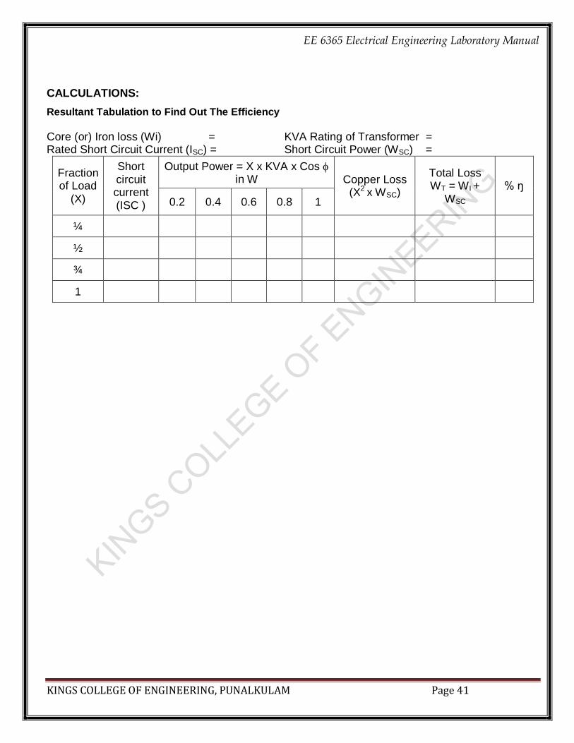
Resultant Tabulation to Find Out The Efficiency
Core (or) Iron loss (Wi) = KVA Rating of Transformer = Rated Short Circuit Current (ISC) = Short Circuit Power (WSC) =
Fraction of Load
(X)
Short circuit current (ISC )
Output Power = X x KVA x Cos in W Copper Loss
(X2 x WSC)
Total Loss WT = WI +
WSC % ŋ
0.2 0.4 0.6 0.8 1
¼
½
¾
1

EE 6365 Electrical Engineering Laboratory Manual
KINGS COLLEGE OF ENGINEERING, PUNALKULAM Page 42
MODEL GRAPH:
EE 6365 Electrical Engineering Laboratory Manual
KINGS COLLEGE OF ENGINEERING, PUNALKULAM Page 43
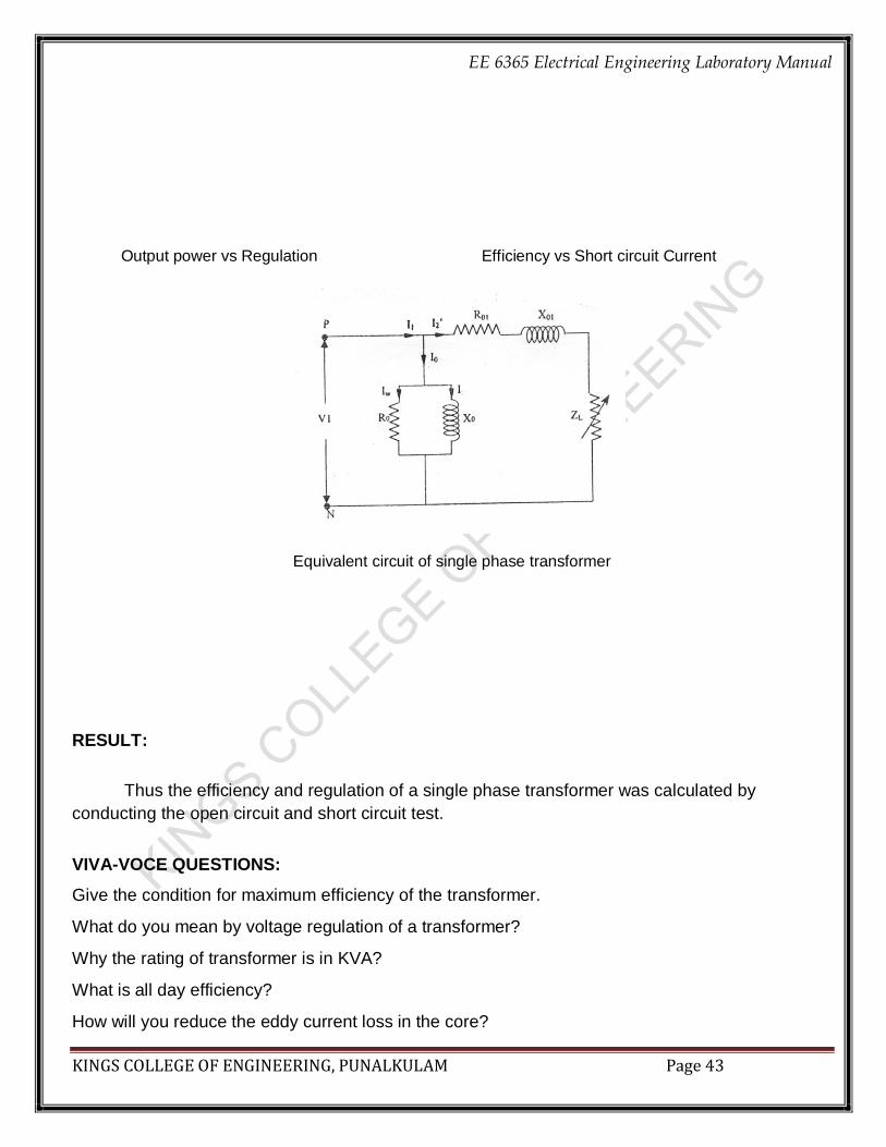
Output power vs Regulation Efficiency vs Short circuit Current
Equivalent circuit of single phase transformer RESULT:
Thus the efficiency and regulation of a single phase transformer was calculated by
conducting the open circuit and short circuit test.
VIVA-VOCE QUESTIONS:
Give the condition for maximum efficiency of the transformer.
What do you mean by voltage regulation of a transformer?
Why the rating of transformer is in KVA?
What is all day efficiency?
How will you reduce the eddy current loss in the core?
EE 6365 Electrical Engineering Laboratory Manual
KINGS COLLEGE OF ENGINEERING, PUNALKULAM Page 44
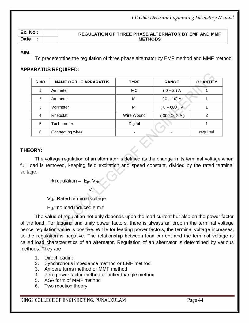
Ex. No : REGULATION OF THREE PHASE ALTERNATOR BY EMF AND MMF METHODS Date :
AIM:
To predetermine the regulation of three phase alternator by EMF method and MMF method.
APPARATUS REQUIRED:
S.NO NAME OF THE APPARATUS TYPE RANGE QUANTITY
1 Ammeter MC ( 0 – 2 ) A 1
2 Ammeter MI ( 0 – 10) A 1
3 Voltmeter MI ( 0 – 600 ) V 1
4 Rheostat Wire Wound ( 300 , 2 A ) 2
5 Tachometer Digital - 1
6 Connecting wires - - required
THEORY:
The voltage regulation of an alternator is defined as the change in its terminal voltage when
full load is removed, keeping field excitation and speed constant, divided by the rated terminal
voltage.
% regulation = Eph-Vph
Vph
Vph=Rated terminal voltage
Eph=no load induced e.m.f
The value of regulation not only depends upon the load current but also on the power factor
of the load. For lagging and unity power factors, there is always an drop in the terminal voltage
hence regulation value is positive. While for leading power factors, the terminal voltage increases,
so the regulation is negative. The relationship between load current and the terminal voltage is
called load characteristics of an alternator. Regulation of an alternator is determined by various
methods. They are
1. Direct loading 2. Synchronous impedance method or EMF method 3. Ampere turns method or MMF method 4. Zero power factor method or potier triangle method 5. ASA form of MMF method 6. Two reaction theory

EE 6365 Electrical Engineering Laboratory Manual
KINGS COLLEGE OF ENGINEERING, PUNALKULAM Page 45
EE 6365 Electrical Engineering Laboratory Manual
KINGS COLLEGE OF ENGINEERING, PUNALKULAM Page 46
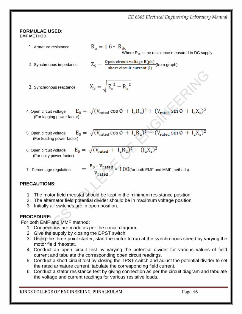
FORMULAE USED: EMF METHOD:
1. Armature resistance
Where Rdc is the resistance measured in DC supply.
2. Synchronous impedance (from graph)
3. Synchronous reactance
4. Open circuit voltage
(For lagging power factor)
5. Open circuit voltage
(For leading power factor)
6. Open circuit voltage
(For unity power factor)
7. Percentage regulation (for both EMF and MMF methods)
PRECAUTIONS:
1. The motor field rheostat should be kept in the minimum resistance position. 2. The alternator field potential divider should be in maximum voltage position 3. Initially all switches are in open position.
PROCEDURE:
For both EMF and MMF method: 1. Connections are made as per the circuit diagram. 2. Give the supply by closing the DPST switch. 3. Using the three point starter, start the motor to run at the synchronous speed by varying the
motor field rheostat. 4. Conduct an open circuit test by varying the potential divider for various values of field
current and tabulate the corresponding open circuit readings. 5. Conduct a short circuit test by closing the TPST switch and adjust the potential divider to set
the rated armature current, tabulate the corresponding field current. 6. Conduct a stator resistance test by giving connection as per the circuit diagram and tabulate
the voltage and current readings for various resistive loads.

EE 6365 Electrical Engineering Laboratory Manual
KINGS COLLEGE OF ENGINEERING, PUNALKULAM Page 47
PROCEDURE TO DRAW THE GRAPH FOR EMF METHOD: 1. Draw the open circuit characteristics curve (generated voltage per phase vs field current) 2. Draw the short circuit characteristics curve(short circuit current vs field current) 3. From the graph find the open circuit voltage per phase (E1(PH)) for rated short circuit
current(ISC). 4. By using respective formulae find the Z, sXs,Eo and percentage regulation. 5. Draw the graph
PROCEDURE TO DRAW THE GRAPH FOR MMF METHOD: 1. Draw the open circuit characteristics curve (generated voltage per phase vs field current) 2. Draw the short circuit characteristics curve (short circuit current vs field current) 3. Draw the line OL to represent IF’ which gives the rated generated voltage (V)
4. Draw the line LA at an angle (90) to represent IF” which gives the rated full load current (ISC)
on short circuit (90+) for lagging power factor and (90-) for leading power factor) 5. Join the points O and A and find the field current (IF) by measuring the distance OA that gives
the open circuit voltage (E0) from the open circuit characteristics. 6. Find the percentage regulation by using suitable formulae. 7. Draw the graph
TABULATION: Tabular Column For Short Circuit Test
S.No Field current(If)A Short circuit current (120 to 150% of rated current) (ISC)A
The Tabular Column For Open Circuit Test
S.No Field
current(If)(A) Open circuit line voltage(VOL)(V)
Open circuit phase voltage(Vo(ph)) (V)
CALCULATIONS:

EE 6365 Electrical Engineering Laboratory Manual
KINGS COLLEGE OF ENGINEERING, PUNALKULAM Page 48

EE 6365 Electrical Engineering Laboratory Manual
KINGS COLLEGE OF ENGINEERING, PUNALKULAM Page 49
Resultant Tabulation for Regulation of Three Phase Alternator By Emf Methods
S.NO
Percentage of regulation
Power factor
EMF METHOD MMF METHOD
Lagging Leading Unity Lagging Leading Unity
1. 0.2 - -
2. 0.4 - -
3. 0.6 - -
4. 0.8 - -
5. 1.0 - - - -
MODEL GRAPH:
EMF METHOD REGULATION CURVE

EE 6365 Electrical Engineering Laboratory Manual
KINGS COLLEGE OF ENGINEERING, PUNALKULAM Page 50
MMF METHOD RESULT:
Thus the regulation of three phase alternator is calculated by EMF and MMF methods. VIVA-VOCE QUESTIONS:
Why alternators are rated in kVA?
What is an alternator?
What is pessimistic method?
What is optimistic method?
What is the need of emf or mmf method?

EE 6365 Electrical Engineering Laboratory Manual
KINGS COLLEGE OF ENGINEERING, PUNALKULAM Page 51
Ex. No : V CURVES AND INVERTED V CURVES OF SYNCHRONOUS MOTOR
Date :
AIM:
To determine the variation of armature current and power factor of a synchronous motor with excitation. APPARATUS REQUIRED:
S.NO NAME OF THE APPARATUS TYPE RANGE QUANTITY
THEORY: If the load remains constant the load angle δ remains unchanged and with changes of field current the back emf developed in the armature changes. If the field excitation is increased, back emf increases and if the field current is decreases the armature induced emf decreases. Let it be assumed that the field xcitation is gradually increased keeping the load on the motor unchanged. Let V= Rated voltage/phase Eb=Back emf/phase δ = load or torque angle Ia= Armature current Φ = power factor angle Active component of current = Ia cos Φ Power input/ phase = V Ia cos Φ As long as the load on the motor remainbs unchanged not only the power angle remains fixed in magnitude, but the power input to the motor is constant. VIa cos Φ= contant But Vis also constant, Therefore for fixed load we have Ia cos Φ = constant. That is the active component of the armature is of constant magnitude. Let the field current increase, this increases the back emf from phasor diagram it can be seen that the resultant voltage phasor Er moves to the left lagging behind it by the fixed angle θ is the armature current phasor Ia.

EE 6365 Electrical Engineering Laboratory Manual
KINGS COLLEGE OF ENGINEERING, PUNALKULAM Page 52
CIRCUIT DIAGRAM:

EE 6365 Electrical Engineering Laboratory Manual
KINGS COLLEGE OF ENGINEERING, PUNALKULAM Page 53
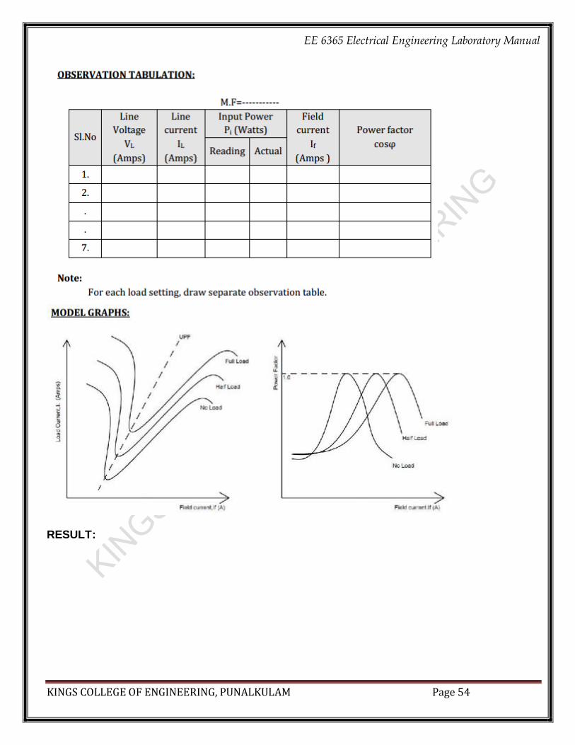
Since the active component of the current is fixed in magn9itude, we have Ia cos Φ1 = Ia cos Φ =OP. But it can be seen that as Er moves leftwards, angle φ progressively decreases. Hence cos Φ increases and Ia decreases. For a certain excitation it so happens that cosφ becomes zero so that Ia is in phase with The P.F is unity is termed as normal excitation. When a synchronous motor is under excited it is evident that the motor draws lagging current and in over excited draws leading current. V curves of the motor can be drawn at different loads as also on no-load. The field excitation which causes minimum armature current of different loads is not same. As the field excitation is gradually increased the motor PF which is lagging increases and at normal excitation it becomes equal to unity. For further increase of field excitation the PF which is now leading progressively decreases. PROCEDURE:
1. Make the connections as per the circuit diagram. 2. Ensuring the minimum resistance in the field circuit of DC motor supply is switched on for the DC motor. 3. Using 3 pointer starter the motor is started and brought to rated speed. 4. The alternator is brought to rated voltage. 5. Keeping the synchronizing switch open 3Ф supply to the alternator is ON, and the following observations are made on synchronizing board i) All the six bulbs are glowing and becoming dark at a time 6. The voltage of alternator is adjusted to supply voltage 7. The speed of alternator is adjusted such that bulbs glow and become dark slowly. 8. At the instant when tyh bulb has no glow (dark) switch is closed. 9. The supply is supplied to alternator and DC motor, this condition is called floating condition which machine driving the other is not known. 10. DC motor supply is switched off so that it can act as generator and alternator will acts as
synchronous motor. 11. The excitation of synchronous motor is at UPF. If the excitation is increased then it acts as leading PF else acts as lagging PF. 12. With out load on DC generator If values for both lag and lead PF is verified and noted the Ia, V
and PF 13. Generator is loaded and above step is repeated. 14. A graph is plotted between If Vs Ia and PF Vs If
EE 6365 Electrical Engineering Laboratory Manual
KINGS COLLEGE OF ENGINEERING, PUNALKULAM Page 54
RESULT:
EE 6365 Electrical Engineering Laboratory Manual
KINGS COLLEGE OF ENGINEERING, PUNALKULAM Page 55
Ex. No : LOAD TEST ON THREE PHASE INDUCTION MOTOR
Date :
AIM:
To conduct the load test on three phase squirrel cage induction motor and to draw the performance characteristic curves.
APPARATUS / INSTRUMENTS REQUIRED:
S.NO NAME OF THE APPARATUS TYPE RANGE QUANTITY
1 Ammeter MI (0-10) A 1
2 Voltmeter MI (0 – 600) V 1
3 Wattmeter UPF (600 V,10 A) 2
4 Tachometer Digital - 1
5 Connecting wires - - Required
FORMULAE USED:
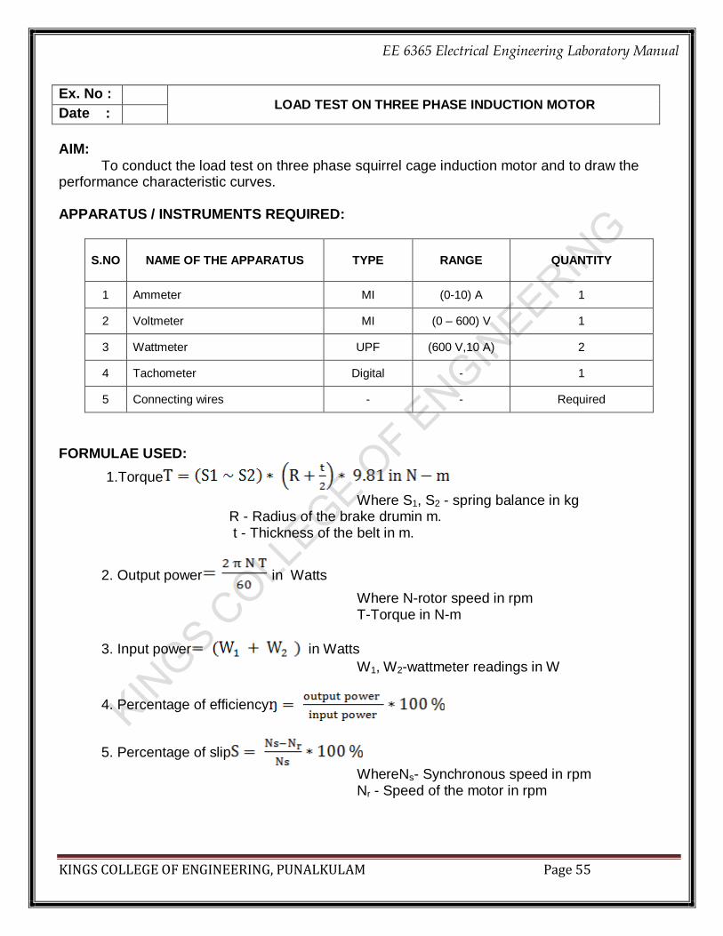
1.Torque
Where S1, S2 - spring balance in kg R - Radius of the brake drumin m. t - Thickness of the belt in m.
2. Output power in Watts
Where N-rotor speed in rpm T-Torque in N-m
3. Input power in Watts
W1, W2-wattmeter readings in W
4. Percentage of efficiency
5. Percentage of slip
WhereNs- Synchronous speed in rpm Nr - Speed of the motor in rpm

EE 6365 Electrical Engineering Laboratory Manual
KINGS COLLEGE OF ENGINEERING, PUNALKULAM Page 56

EE 6365 Electrical Engineering Laboratory Manual
KINGS COLLEGE OF ENGINEERING, PUNALKULAM Page 57
6. Power factor
Where VL – Line voltage IL – Line current
PRECAUTIONS:
The motor should be started without load PROCEDURE:
1. Note down the name plate details of the motor. 2. Make the Connections as per the circuit diagram. 3. The TPST switch is closed and the motor is started using star delta starter to run at rated
speed. 4. At no load the speed, current, voltage and power are noted. 5. By applying the load for various values of current and the above mentioned readings are noted
in tabular column 6. The load is later released and the motor is switched off and the graph is drawn.
TABULATION: Circumference of brake drum = in m Thickness of the belt = in m
Multiplication Factor for W1 = Multiplication Factor for W2 =

EE 6365 Electrical Engineering Laboratory Manual
KINGS COLLEGE OF ENGINEERING, PUNALKULAM Page 58
CALCULATIONS:

EE 6365 Electrical Engineering Laboratory Manual
KINGS COLLEGE OF ENGINEERING, PUNALKULAM Page 59
MODEL GRAPH:
Mechanical Characteristics Electrical Characteristics
RESULT: Thus the load test on three phase squirrel cage induction motor was conducted and the
performance characteristic curves were drawn. VIVA-VOCE QUESTIONS:
What is an induction motor?
What is the advantage of three phase induction motor?
What are the types of ac machines?
What are the types of induction motor?
What is the standard efficiency of induction motor?

EE 6365 Electrical Engineering Laboratory Manual
KINGS COLLEGE OF ENGINEERING, PUNALKULAM Page 60
AIM :
To control the speed of three phase slip ring induction motor and draw its performance characteristics.
APPARATUS / INSTRUMENTS REQUIRED:
S.NO NAME OF THE APPARATUS TYPE RANGE QUANTITY
THEORY: Rotor Rheostat Control:
In this method, which is applicable to slip ring induction motors alone, the motor speed is reduced by introducing an external resistance in the rotor circuit. For this purpose, the rotor starter may be used provided it is continuously rated. This method is in fact similar to the armature rheostat control method of d.c shunt motors. PROCEDURE :
1. The connections are given as per the circuit diagram.
2. The A.C supply is given to the motor by closing the TPST switch.
3. Initially resistance of the rotor resistance starter is kept at maximum resistance position.
4. Now gradually reduce the resistance of the rotor resistance starter and note down the corresponding meter readings.
GRAPH: Draw a graph of rotor external resistance versus speed.
Ex. No : SPEED CONTROL OF THREE PHASE SLIP RING INDUCTION MOTOR Date :

EE 6365 Electrical Engineering Laboratory Manual
KINGS COLLEGE OF ENGINEERING, PUNALKULAM Page 61
TABULATION:
CIRCUIT DIAGRAM:

EE 6365 Electrical Engineering Laboratory Manual
KINGS COLLEGE OF ENGINEERING, PUNALKULAM Page 62
RESULT : Thus the speed of 3 phase slip ring induction motor was controlled by rotor resistance control
method.

EE 6365 Electrical Engineering Laboratory Manual
KINGS COLLEGE OF ENGINEERING, PUNALKULAM Page 63
AIM: To conduct load test on single phase induction motor and to draw the performance characteristics. APPARATUS REQUIRED:
S.NO APPARATUS RANGE TYPE QUANTITY
FORMULA:
PRECAUTION:
The motor should be at the no load condition while starting. PROCEDURE: 1. Connections are given as per the circuit diagram. 2. The induction motor is started on no load by using transformer starter. 3. Under no load condition, reading of ammeter, voltmeter and wattmeter are noted down. 4. Speed is measured by using tachometer. 5. The motor is loaded gradually by increasing tension on the belt over the brake drum. 6. At each load, the readings of ammeter, voltmeter and wattmeter are noted, speed is measured and spring balance readings are noted down. 7. The above procedure is repeated till the rated current is reached. 8. The load on motor is gradually reduced to zero and then supply is switched OFF
Ex. No : LOAD TEST ON SINGLE PHASE INDUCTION MOTOR Date :

EE 6365 Electrical Engineering Laboratory Manual
KINGS COLLEGE OF ENGINEERING, PUNALKULAM Page 64
CIRCUIT DIAGRAM:

EE 6365 Electrical Engineering Laboratory Manual
KINGS COLLEGE OF ENGINEERING, PUNALKULAM Page 65
MODEL GRAPHS:
EE 6365 Electrical Engineering Laboratory Manual
KINGS COLLEGE OF ENGINEERING, PUNALKULAM Page 66
MODEL CALCULATION:
RESULT: Thus load test on the single phase induction motor has been conducted and its performance
characteristics determined.
EE 6365 Electrical Engineering Laboratory Manual
KINGS COLLEGE OF ENGINEERING, PUNALKULAM Page 67
Ex. No : OPEN CIRCUIT AND LOAD CHARACTERISTICS OF SEPARATELY EXCITED D.C GENERATOR Date :

EE 6365 Electrical Engineering Laboratory Manual
KINGS COLLEGE OF ENGINEERING, PUNALKULAM Page 68
AIM: To draw the open circuit and load characteristics of separately excited DC generator by
conducting open circuit test and load test on it.
APPARATUS REQUIRED:
S.NO. APPARATUS REQUIRED TYPE RANGE QUANTITY
1 Ammeter MC (0-2)A 1
2 Ammeter MC (0-20)A 1
3 Voltmeter MC (0-50)V 1
4 Voltmeter MC (0-300)V 1
5 Rheostat Wire wound 300 ,1.7A 1
6 Rheostat Wire wound 300 ,2A 1
7 Resistive load - 3KW 1
8 Tachometer Digital - 1
9 Connecting wires - - Req
THEORY:
The induced emf is proportional to the flux and the speed. If the speed is maintained constant and the field current is varied, then the induced emf also varies. The variation of flux with the induced emf is called no load magnetization curve or saturation curve or open circuit characteristics curve. When the current in the field is zero, there is some flux due to residual magnetism and this causes a small induced voltage. This is called the remnant voltage and is due to retentivity of the magnetic poles. As the load current and the armature current increases, the terminal voltage drops due to armature reaction and voltage drop across armature resistance. So obtained characteristics are known as external or load characteristics.
FORMULAE USED:
Where
- Generated emf at load condition in V - Terminal voltage in V
CIRCUIT DIAGRAM

EE 6365 Electrical Engineering Laboratory Manual
KINGS COLLEGE OF ENGINEERING, PUNALKULAM Page 69
- Armature resistance in ohm - Load current in A

EE 6365 Electrical Engineering Laboratory Manual
KINGS COLLEGE OF ENGINEERING, PUNALKULAM Page 70
- Field current in A - Armature voltage in V
PRECAUTIONS:
All the DPST switch should be kept open Motor field rheostat should be in minimum position only Generated field rheostat should be in maximum position only All the switches in resistive load should be in off position In the measurement of armature resistance, rheostat should be in maximum resistance
position PROCEDURE: A.OPEN CIRCUIT TEST: 1. Make the connection as per the circuit diagram. 2. Close the DPST switch. 3. Start the motor using three point starter. 4. By adjusting motor field rheostat set the motor-generator to its rated speed 5. Note down the generator voltage indicated by the voltmeter in table. 6. Adjust the generator field rheostat and note down the field current (If) &generator emf (Eo)
indicated by the ammeter and voltmeter respectively. 7. Repeat the same procedure until the voltmeter reads rated voltage of DC Generator.
Tabulation for Open Circuit Test of Separately Excited DC Generator
S.No. Field current If in A Generated emf Eg in V
B. LOAD TEST:
1. Now close the DPST switch. 2. Adjust the resistive load and note down the corresponding load current IL and terminal voltage
indicated by the ammeter and voltmeter respectively in table. 3. Repeat the same procedure till the load current reaches the rated load current.
Tabulation for Load test of Separately Excited DC Shunt Generator

EE 6365 Electrical Engineering Laboratory Manual
KINGS COLLEGE OF ENGINEERING, PUNALKULAM Page 71
S.No. Load current
(IL in A) Terminal voltage
(Vt in V) Armature current
(Ia in A)
Generated voltage (Eg in V)
CALCULATIONS:

EE 6365 Electrical Engineering Laboratory Manual
KINGS COLLEGE OF ENGINEERING, PUNALKULAM Page 72
MODEL GRAPH:
Graph Representing the Magnetization or Open Circuit Characteristics of Separately Excited DC Generator.
Graph Representing the Load Characteristics of Separately Excited DC Generator.
RESULT: Thus the open circuit and load test on Separately Excited DC Generator was conducted and the magnetization and load characteristics were drawn.
VIVA-VOCE QUESTIONS:
What is a shunt generator? What is separately excited? How should a generator be started? What is the permissible rise of temperature in a well designed generator? Will a generator build up if it becomes reversed? What is the standard direction of rotation of DC generators?

EE 6365 Electrical Engineering Laboratory Manual
KINGS COLLEGE OF ENGINEERING, PUNALKULAM Page 73
Ex. No :
Date :
AIM:
APPARATUS / INSTRUMENTS REQUIRED: THEORY:
FORMULAE USED: PRECAUTIONS: PROCEDURE: TABULATION: CALCULATIONS:
MODEL GRAPH: RESULT: VIVA-VOCE QUESTIONS:
Ex. No :
Date :
AIM:
APPARATUS / INSTRUMENTS REQUIRED: THEORY:
FORMULAE USED: PRECAUTIONS:
EE 6365 Electrical Engineering Laboratory Manual
KINGS COLLEGE OF ENGINEERING, PUNALKULAM Page 74
PROCEDURE: TABULATION: CALCULATIONS:
MODEL GRAPH: RESULT: VIVA-VOCE QUESTIONS:
Ex. No :
Date :
AIM:
APPARATUS / INSTRUMENTS REQUIRED: THEORY:
FORMULAE USED: PRECAUTIONS: PROCEDURE: TABULATION: CALCULATIONS:
MODEL GRAPH: RESULT: VIVA-VOCE QUESTIONS:
Ex. No :

EE 6365 Electrical Engineering Laboratory Manual
KINGS COLLEGE OF ENGINEERING, PUNALKULAM Page 75
Date :
AIM:
APPARATUS / INSTRUMENTS REQUIRED: THEORY:
FORMULAE USED: PRECAUTIONS: PROCEDURE: TABULATION: CALCULATIONS:
MODEL GRAPH: RESULT: VIVA-VOCE QUESTIONS:
Related Documents


![gafi.gov.eg · ˛ ˚ ˜ 2 2017 ˘ˇ ˆ ˙˝ ˆ˜ ˙ !"˛ ˆ˙˝ ˛ ˚ ˆ eeeb˚ ˚ eee7 *eee˚ n eee_ & eee˙ ] 1ˆeee ^ eee7: x eee˜](https://static.cupdf.com/doc/110x72/5f26ba0f663eb944d5594a4b/gafigoveg-oe-2-2017-oe-eeeb.jpg)