EECE251 Circuit Analysis I Lecture Integrated Program 1 SM EECE 251, Set 5 Set 5: First-Order and Second-Order Linear Circuits Shahriar Mirabbasi Department of Electrical and Computer Engineering University of British Columbia [email protected]

Welcome message from author
This document is posted to help you gain knowledge. Please leave a comment to let me know what you think about it! Share it to your friends and learn new things together.
Transcript
EECE251
Circuit Analysis ILecture Integrated Program
1SMEECE 251, Set 5
Lecture Integrated Program
Set 5: First-Order and Second-Order Linear Circuits Shahriar Mirabbasi
Department of Electrical and Computer EngineeringUniversity of British Columbia
Overview
• Passive elements that we have seen so far: resistors, inductors, andcapacitors.
• We have already seen different methods to analyze circuits containingsources and resistive elements.
• Now we want to examine circuits that contain various combinations oftwo or three different types of these passive elements.
2SMEECE 251, Set 5
two or three different types of these passive elements.
• We start with circuits whose passive elements are resistors and one(equivalent) capacitor (RC circuits) or resistors and one (equivalent)inductor (RL circuits)
• Similar to circuits whose passive elements are all resistive, one cananalyze RC or RL circuits by applying KVL and/or KCL. Is the analysisof RC or RL circuits any different?
Note: Some of the figures in this slide set are taken from (R. Decarlo and P.-M. Lin, Linear Circuit Analysis, 2ndEdition, 2001, OxfordUniversity Press) and (C.K. Alexander and M.N.O Sadiku, Fundamentals of Electric Circuits, 4th Edition, 2008, McGraw Hill)

Capacitors (Refresher)
• Capacitors store energy (in the electric field between theirplates)
• For capacitors we have:
3SM
• For capacitors we have:
EECE 251, Set 5
)t(Cv)t(q CC =
)()(1
)()(1)(
)( 0
0
tvdiC
tvdiCC
tqtv C
t
t
CC
t
CC or +⋅=⋅== ∫∫∞−
ττττ
dt
tdvCti C
C
)()( ⋅=
Capacitors (Refresher)
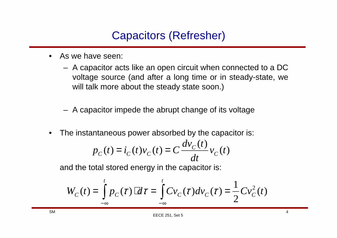
• As we have seen:– A capacitor acts like an open circuit when connected to a DC
voltage source (and after a long time or in steady-state, wewill talk more about the steady state soon.)
– A capacitor impede the abrupt change of its voltage
4SMEECE 251, Set 5
• The instantaneous power absorbed by the capacitor is:
and the total stored energy in the capacitor is:
)()(
)()()( tvdt
tdvCtvtitp C
CCCC ==
)(2
1)()()()( 2 tCvdvCvdptW C
t
CC
t
CC ==⋅= ∫∫∞−∞−
ττττ

Inductors (Refresher)
• Inductors store energy in their magnetic field.
• For inductors, we have
tdiLtv L )(
)( ⋅=
5SMEECE 251, Set 5
dt
tdiLtv L
L
)()( ⋅=
)()(1
)()(1
)( 0
0
tidvL
tidvL
ti L
t
t
LL
t
LL or +⋅=⋅= ∫∫∞−
ττττ

Inductors (Refresher)
• An inductor acts like a short circuit to DC current (in steadystate).
• Inductor impede instantaneous changes of its current.
• Instantaneous power delivered to the inductor is:
6SMEECE 251, Set 5
• The total stored energy in an inductor is:
)()(
)()()( tidt
tdiLtitvtp L
LLLL ==
)(2
1)()()()( 2 tLidiLidptW L
t
LL
t
LL ==⋅= ∫∫ ∞−∞−ττττ

Steady-State Response
• Loosely speaking, the behaviour of the circuit a long time afteran excitation is applied to the circuit is called steady-stateresponse.
• For example, if in a circuit a switch is opened (or closed) theresponse of the circuit to this excitation long time after the switchis opened (or closed) is referred to as steady-state response.
7SM
is opened (or closed) is referred to as steady-state response.
• If we only have DC sources in the circuit, at steady statecapacitors act like open circuit and inductors act like a shortcircuit.
EECE 251, Set 5
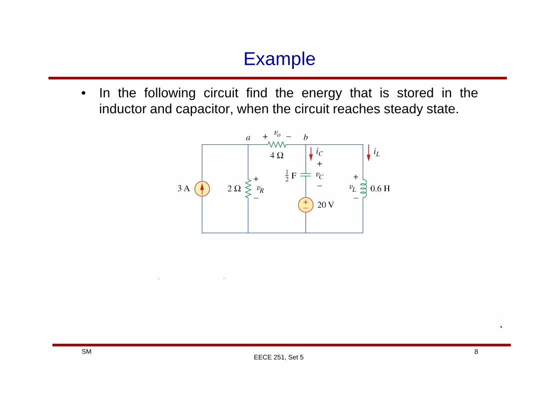
Example
• In the following circuit find the energy that is stored in theinductor and capacitor, when the circuit reaches steady state.
8SMEECE 251, Set 5
Example
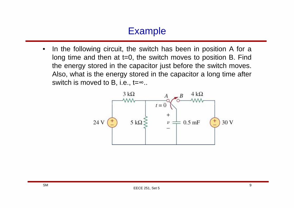
• In the following circuit, the switch has been in position A for along time and then at t=0, the switch moves to position B. Findthe energy stored in the capacitor just before the switch moves.Also, what is the energy stored in the capacitor a long time afterswitch is moved to B, i.e., t=∞..
9SMEECE 251, Set 5
Example
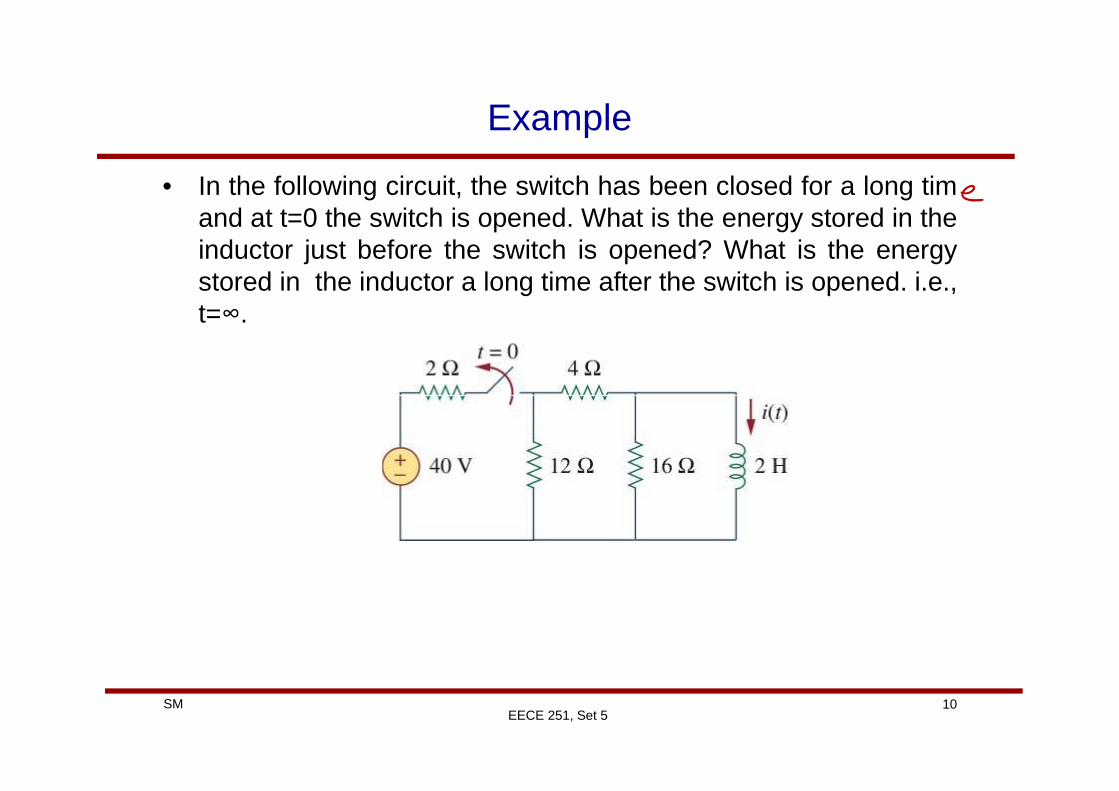
• In the following circuit, the switch has been closed for a long timand at t=0 the switch is opened. What is the energy stored in theinductor just before the switch is opened? What is the energystored in the inductor a long time after the switch is opened. i.e.,t=∞.
10SMEECE 251, Set 5
First-Order Circuits
• Applying KVL and/or KCL to purely resistive circuits results inalgebraic equations.
• Applying these laws to RC and RL circuits results in differentialequations.
• In general, differential equations are a bit more difficult to solve
11SMEECE 251, Set 5
• In general, differential equations are a bit more difficult to solvecompared to algebraic equations!
• If there is only one C or just one L in the circuit the resultingdifferential equation is of the first order (and it is linear).
• A circuit that is characterized by a first-order differentialequation is called a first-order circuit.

What Do We Mean By Equivalent Capacitor?
• The equivalent capacitance of series-connected capacitors isthe reciprocal of the sum of the reciprocals of the individualcapacitances. Why?
neq CCCC
1111
21
+++= L
12SMEECE 251, Set 5
• The equivalent capacitance of parallel capacitors is the sum ofthe individual capacitances. Why?
neq CCCC +++= L21

What Do We Mean by Equivalent Inductor?
• The equivalent inductance of series-connected inductors is thesum of the individual inductances. Why?
neq LLLL +++= L21
13SMEECE 251, Set 5
• The equivalent inductance of parallel inductors is the reciprocalof the sum of the reciprocals of the individual inductances. Why?
neq LLLL
1111
21
+++= L
First-Order Circuits
• So in an RC circuit if we have more than one capacitor,however, we can combine the capacitors (series and/or parallelcombination) and represent them with one equivalent capacitor,we still have a first-order circuit.
• The same is true for RL circuits, that is if we can combine all theinductors and represent them with one equivalent circuit then we
14SM
inductors and represent them with one equivalent circuit then westill have a first-order circuit
• In such circuits we can find the Thevenin (or Norton) equivalentcircuit seen by the equivalent capacitor (or Inductor) and thensolve the circuit.
• Let’s start with the circuits that have no source!
EECE 251, Set 5
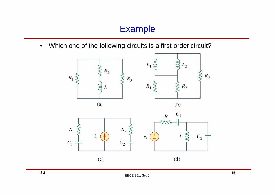
Example
• Which one of the following circuits is a first-order circuit?
15SMEECE 251, Set 5

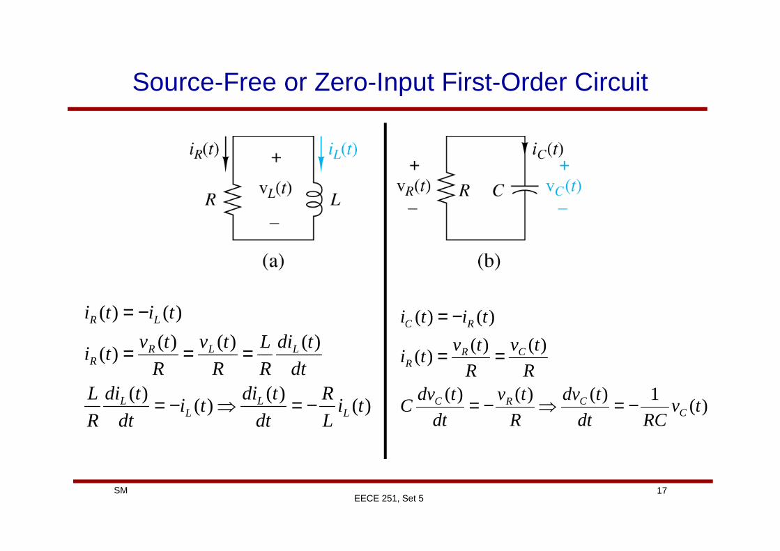
Source-Free or Zero-Input First-Order Circuit
• Recall that in general if there is only one (equivalent) inductor orcapacitor in the circuit one can model the circuit seen by theinductor or capacitor by its Thevenin equivalent circuit.
• In the case of source-free circuit (no independent source in thecircuit) the Thevenin equivalent circuit will be…………..a resistor.
16SMEECE 251, Set 5
Source-Free or Zero-Input First-Order Circuit
17SMEECE 251, Set 5
)()(
)()(
)()()()(
)()(
tiL
R
dt
tditi
dt
tdi
R
Ldt
tdi
R
L
R
tv
R
tvti
titi
LL
LL
LLRR
LR
−=⇒−=
===
−=
)(1)()()(
)()()(
)()(
tvRCdt
tdv
R
tv
dt
tdvC
R
tv
R
tvti
titi
CCRC
CRR
RC
−=⇒−=
==
−=

Source-Free First-Order RC Circuit
• Let’s assume that we know the charge or equivalently thevoltage across the capacitor at time 0. That is: 0)0( VvC =
18SMEECE 251, Set 5
• Recall:
• Let’s try to solve this differential equation. Because of the simpleform of this equation we can re-arrange the term as:
)(1)(
0)()(
0)()( tvRCdt
tdv
R
tv
dt
tdvCtiti C
CCCRC −=⇒=+⇒=+
dtRCtv
tdv
C
C 1
)(
)( −=
Source-Free First-Order RC Circuit
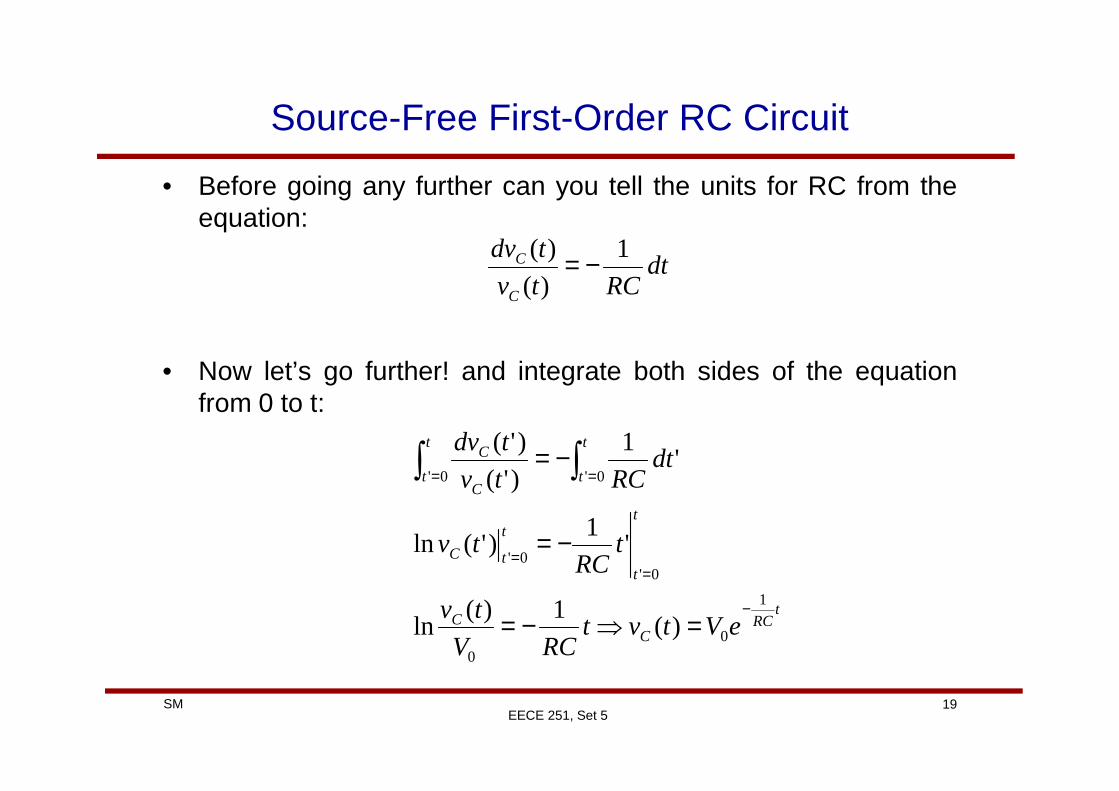
• Before going any further can you tell the units for RC from theequation:
• Now let’s go further! and integrate both sides of the equationfrom 0 to t:
dtRCtv
tdv
C
C 1
)(
)( −=
19SMEECE 251, Set 5
from 0 to t:
tRC
CC
t
t
t
tC
t
t
t
tC
C
eVtvtRCV
tv
tRC
tv
dtRCtv
tdv
1
00
0'0'
0'0'
)(1)(
ln
'1
)'(ln
'1
)'(
)'(
−
==
==
=⇒−=
−=
−= ∫∫
Source-Free First-Order RC Circuit
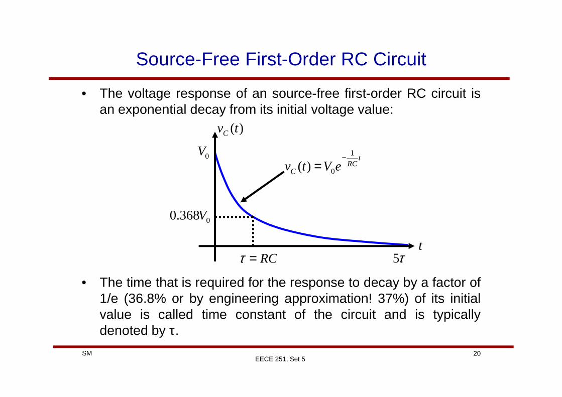
• The voltage response of an source-free first-order RC circuit isan exponential decay from its initial voltage value:
tRC
C eVtv1
0)(−
=
)(tvC
0V
20SMEECE 251, Set 5
• The time that is required for the response to decay by a factor of1/e (36.8% or by engineering approximation! 37%) of its initialvalue is called time constant of the circuit and is typicallydenoted by τ.
t
0368.0 V
RC=τ τ5
Source-Free First-Order RC Circuit
• Philosophical question: When there is no source in the circuit,how come we have such a response? What is the response dueto?
• In general, the response of a source-free circuit which is due tothe initial energy stored in the storage elements (in this case C)and not due to external sources is called natural response.
21SMEECE 251, Set 5
• In first order RC (and RL) circuits natural response is a decayingexponential.
• To find the natural response of a first-order RC circuit we needtwo pieces of information:– Initial voltage across the capacitor– The time constant τ=RC

Source-Free First-Order RC Circuit
• Time constant of the circuit gives us an indication of how rapidlythe response decays, in other words how fast is the response.
• Let’s calculate the natural response for times equaldifferent multiples of the time constant:
tRC
C eVtv1
0)(−
=
t vC(t)
τ 0.3679V0
22SMEECE 251, Set 5
• For all practical purposes it is typically assumed that theresponse reaches its final value after 5τ.
τ 0.3679V0
2τ 0.1353V0
3τ 0.0498V0
4τ 0.0183V0
5τ 0.0067V0
Example
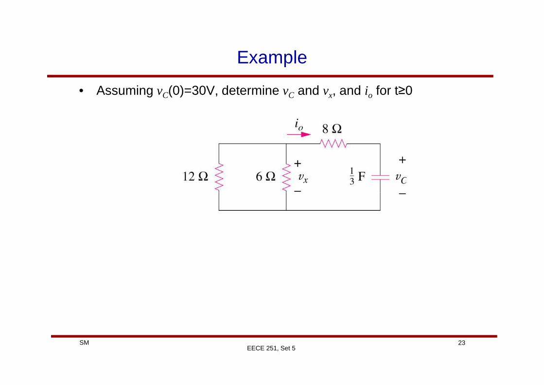
• Assuming vC(0)=30V, determine vC and vx, and io for t≥0
23SMEECE 251, Set 5
Source-Free First-Order RC Example
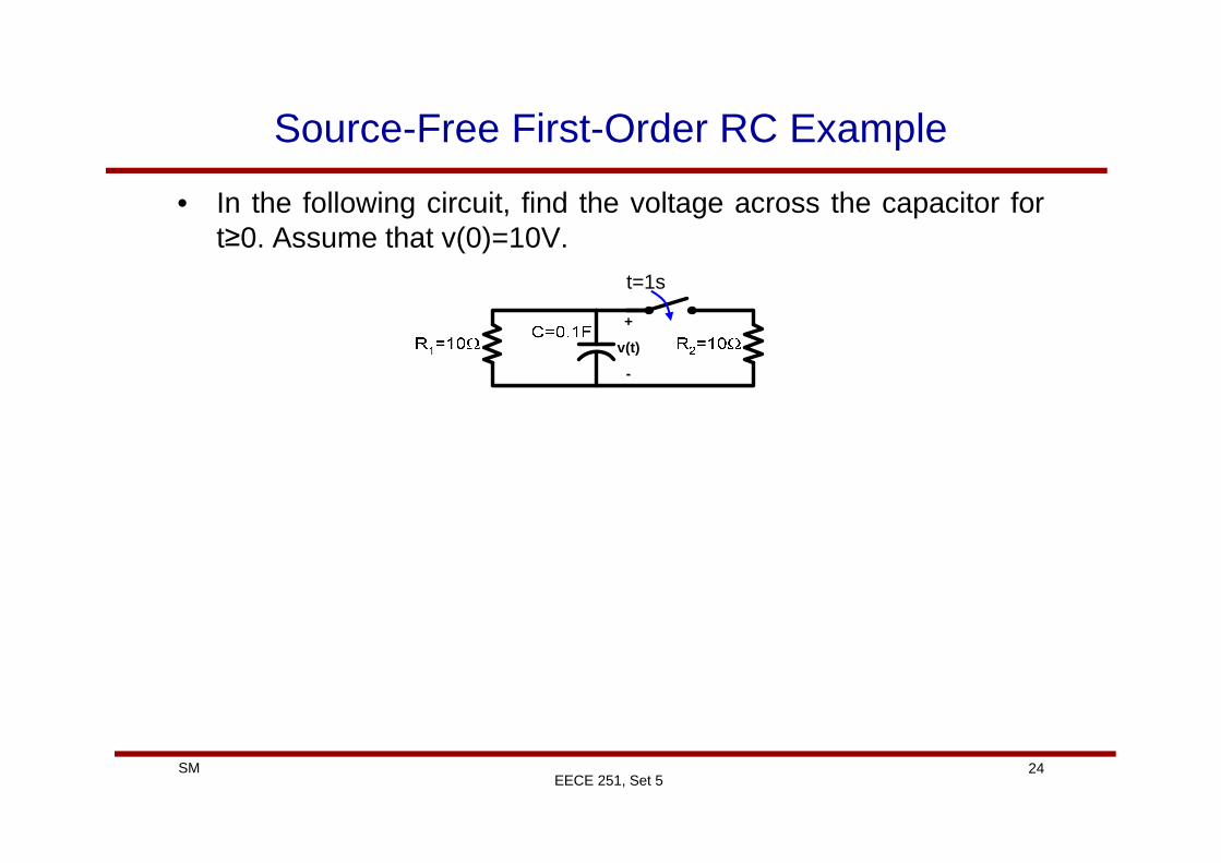
• In the following circuit, find the voltage across the capacitor fort≥0. Assume that v(0)=10V.
t=1s
+
v(t)
-
24SMEECE 251, Set 5
Source-Free First-Order RL Circuit
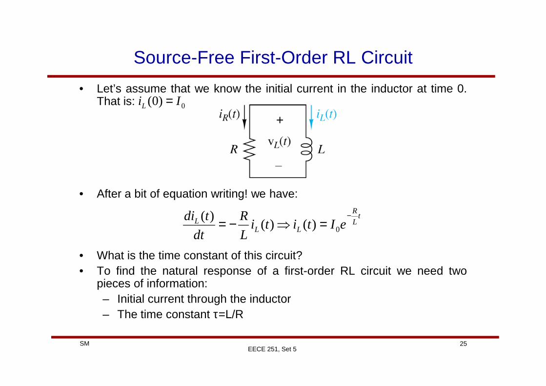
• Let’s assume that we know the initial current in the inductor at time 0.That is:
• After a bit of equation writing! we have:
0)0( IiL =
25SMEECE 251, Set 5
• After a bit of equation writing! we have:
• What is the time constant of this circuit?• To find the natural response of a first-order RL circuit we need two
pieces of information:– Initial current through the inductor– The time constant τ=L/R
tL
R
LLL eItiti
L
R
dt
tdi −=⇒−= 0)()(
)(
Source-Free First-Order RL Example
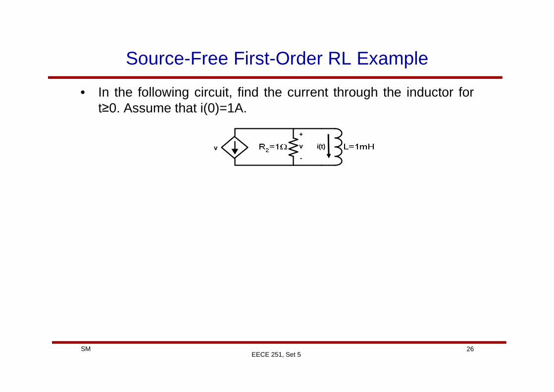
• In the following circuit, find the current through the inductor fort≥0. Assume that i(0)=1A.
+
v
-
v i(t)
26SMEECE 251, Set 5
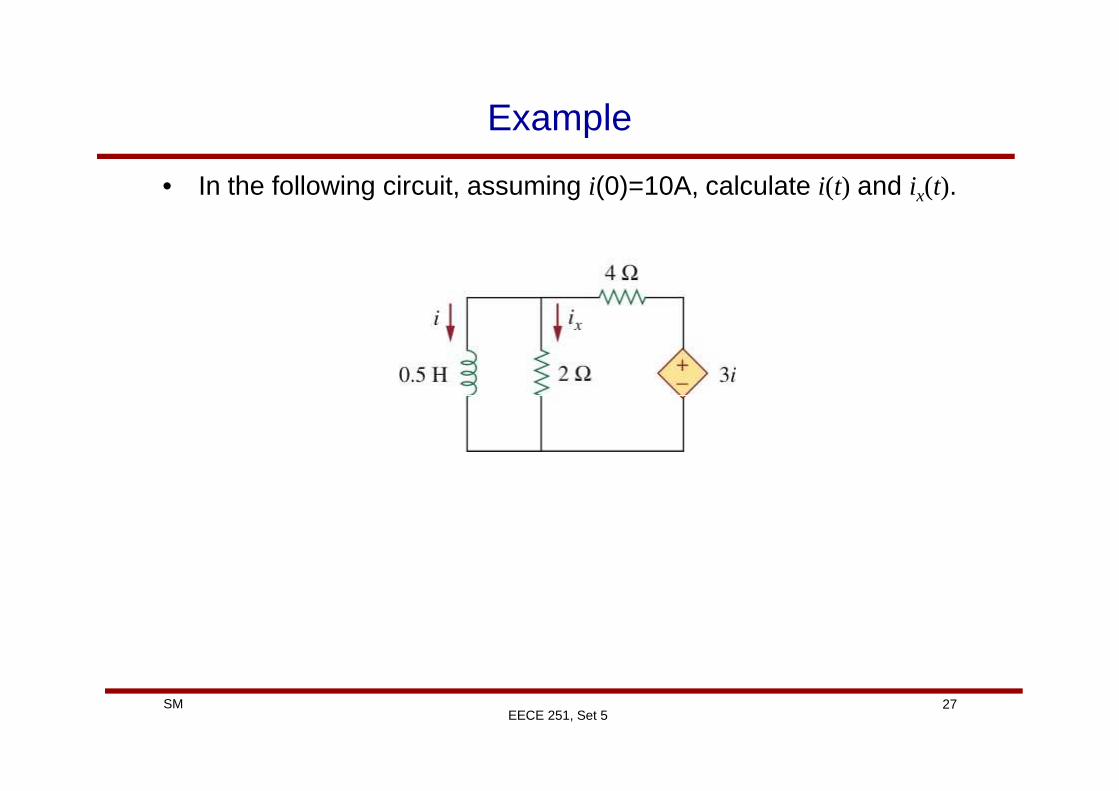
Example
• In the following circuit, assuming i(0)=10A, calculate i(t) and ix(t).
27SMEECE 251, Set 5
Unit Step Function
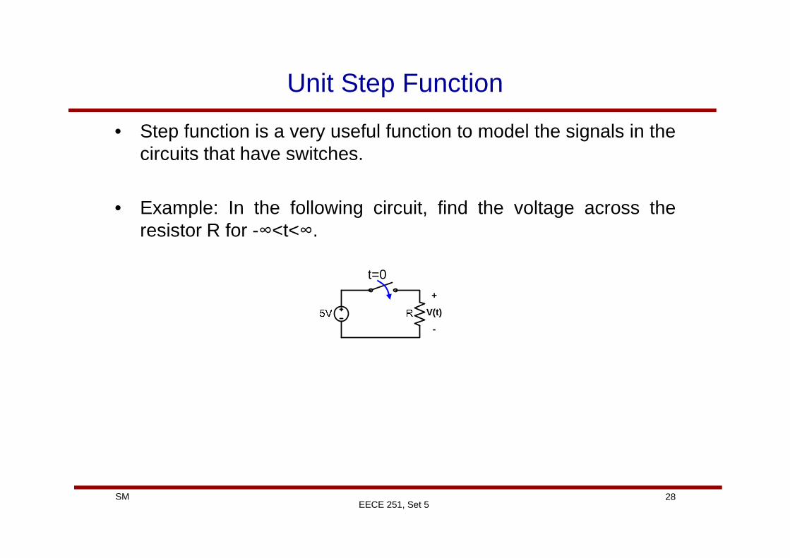
• Step function is a very useful function to model the signals in thecircuits that have switches.
• Example: In the following circuit, find the voltage across theresistor R for -∞<t<∞.
t=0
28SMEECE 251, Set 5
t=0
+
V(t)
-
Unit Step Function
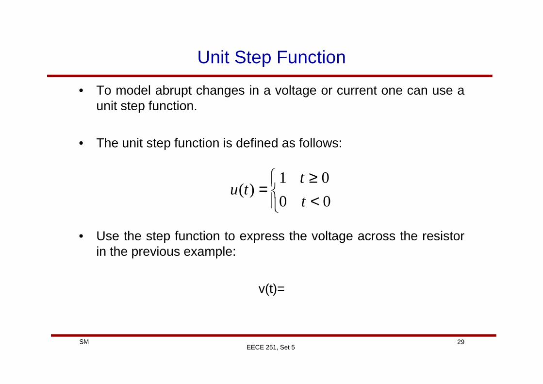
• To model abrupt changes in a voltage or current one can use aunit step function.
• The unit step function is defined as follows:
<≥
=01
)(t
tu
29SMEECE 251, Set 5
• Use the step function to express the voltage across the resistorin the previous example:
v(t)=
<
=00
)(t
tu
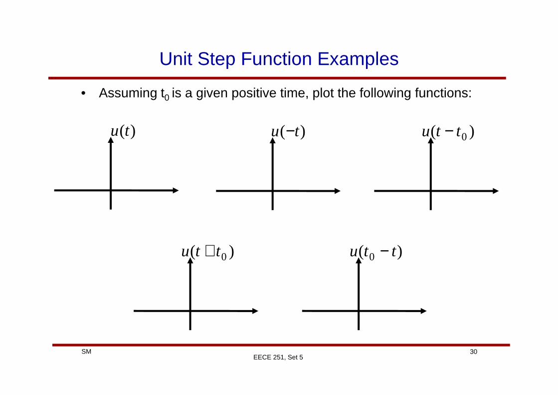
Unit Step Function Examples
• Assuming t0 is a given positive time, plot the following functions:
)(tu )( tu − )( 0ttu −
30SMEECE 251, Set 5
)( 0ttu + )( 0 ttu −
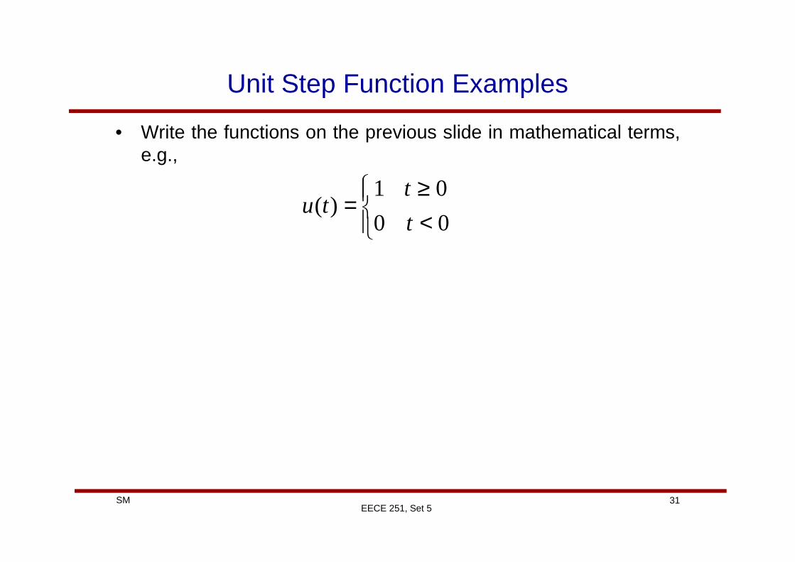
Unit Step Function Examples
• Write the functions on the previous slide in mathematical terms,e.g.,
<≥
=00
01)(
t
ttu
31SMEECE 251, Set 5

Singularity Functions
• Singularity functions are functions that either are discontinuousor have discontinuous derivatives.
• Three widely used singularity functions in circuit analysis are theunit step, the unit impulse, and the unit ramp functions.
<t 0,0
32SMEECE 251, Set 5
∫
≥<
===
>=<
==
∞−
t
tt
tttudttutr
t
tundefined
t
dt
tdut
0,
0,0)(')'()(
00
0,
0,0)(
)(δ
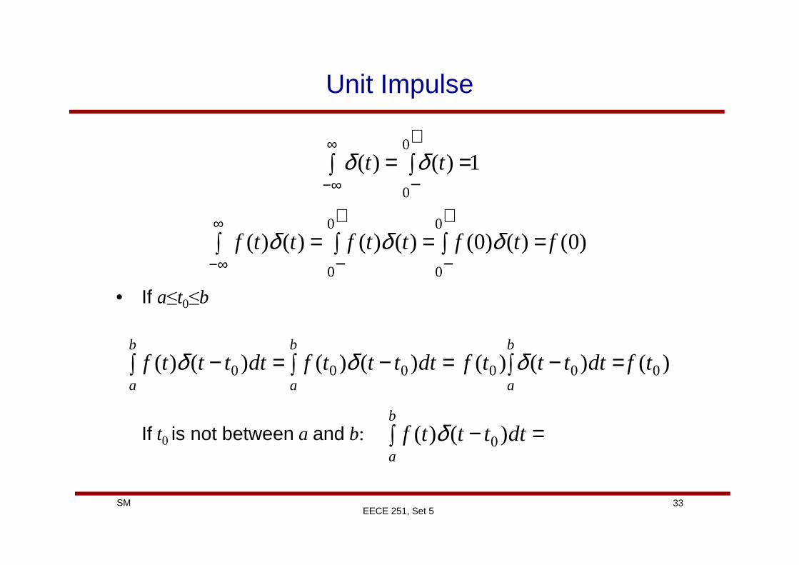
Unit Impulse
∫ ∫ ==∞
∞−
+
−1)()(
0
0
tt δδ
∫ ∫ =∫ ==∞
∞−
+
−
+
−)0()()0()()()()(
0
0
0
0
ftfttfttf δδδ
33SMEECE 251, Set 5
• If a≤t0≤b
If t0 is not between a and b:
∫ ∫ ∫ =−=−=−b
a
b
a
b
a
tfdttttfdttttfdttttf )()()()()()()( 000000 δδδ
∫ =−b
a
dttttf )()( 0δ

Some Mathematical Background
• In general, the differential equations that model first-order RC orRL circuits are of the form:
valid for where x(t) is the voltage or current of interest andx0 is the initial condition at time t0.
00 )(),()()(
xtxtftxdt
tdx=+= λ
,0tt ≥
34SMEECE 251, Set 5
• Let’s briefly review a technique (called integrating factormethod) to solve this type of differential equations:
)()()(
)()()(
tftxdt
tdxtftx
dt
tdx=−⇒+= λλ
[ ] )()(
)()()(
tfetxedt
d
tfetxedt
tdxe
tt
ttt
λλ
λλλ λ
−−
−−−
=⇒
=−⇒
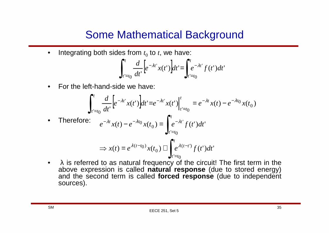
Some Mathematical Background
• Integrating both sides from t0 to t, we have:
• For the left-hand-side we have:
• Therefore:
[ ] ∫∫ =
−
=
− =t
tt
tt
tt
t dttfedttxedt
d
0'
'
0'
' ')'(')'('
λλ
[ ] )()()'(')'('
00
0'
'
0'
' txetxetxedttxedt
d ttt
tt
tt
tt
t λλλλ −−
=
−
=
− −==∫∫
t
35SMEECE 251, Set 5
• Therefore:
• λ is referred to as natural frequency of the circuit! The first term in theabove expression is called natural response (due to stored energy)and the second term is called forced response (due to independentsources).
∫∫
=
−−
=
−−−
+=⇒
=−
t
tt
tttt
t
tt
ttt
dttfetxetx
dttfetxetxe
0'
)'(0
)0(
0'
'0
0
')'()()(
')'()()(
λλ
λλλ
DC or Step-Response of First-Order Circuits
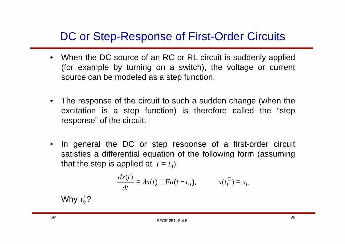
• When the DC source of an RC or RL circuit is suddenly applied(for example by turning on a switch), the voltage or currentsource can be modeled as a step function.
• The response of the circuit to such a sudden change (when theexcitation is a step function) is therefore called the “stepresponse” of the circuit.
36SMEECE 251, Set 5
response” of the circuit.
• In general the DC or step response of a first-order circuitsatisfies a differential equation of the following form (assumingthat the step is applied at t = t0):
Why ?
000 )(),()()(
xtxttFutxdt
tdx=−+= +λ
+0t

DC or Step-Response of First-Order Circuits
• For t ≥ t0 we can rewrite the equation as:• Then the solution would be:
'
'0
)0(
0'
)'(0
)0(
')(
')()(
t
tt
tttt
t
tt
tttt
dteFetxe
Fdtetxetx
=
−+−
=
−+−
+=
+=
∫
∫λλλ
λλ
00 )(,)()(
xtxFtxdt
tdx=+= +λ
37SMEECE 251, Set 5
[ ])0(0
)0(
00
)0(
0'
'0
)0(
0'
1)(
)(
1)(
tttt
ttttt
t
tt
tttt
tt
eF
txe
eeeF
txe
eFetxe
−+−
−−+−
=
−+−
=
−−=
−−=
−+=
∫
λλ
λλλλ
λλλ
λ
λ
λ

DC or Step-Response of First-Order Circuits
• For first-order circuits:• Therefore:
• Note that:
−+=
−−+
−−
ττ τ)0(
0
)0(
1)()(tttt
eFtxetx
τλ 1−=
τFtxxt
==∞∞→
)(lim)(
38SMEECE 251, Set 5
• Thus the step response of a first order circuit has the followinggeneral form:
The step response of any voltage or current in a first-ordercircuit has the above general form.
t ∞→
[ ] )()()()()0(
0 ∞+∞−=−
−+ xextxtxtt
τ
DC or Step-Response of First-Order Circuits
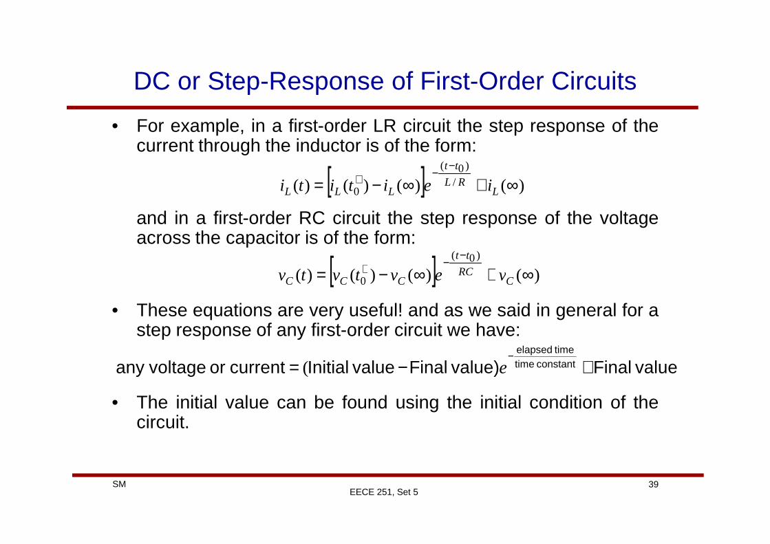
• For example, in a first-order LR circuit the step response of thecurrent through the inductor is of the form:
and in a first-order RC circuit the step response of the voltageacross the capacitor is of the form:
[ ] )()()()( /
)0(
0 ∞+∞−=−
−+L
RL
tt
LLL ieititi
[ ] )()()()()0(
∞+∞−=−
−+ RC
tt
vevtvtv
39SMEECE 251, Set 5
• These equations are very useful! and as we said in general for astep response of any first-order circuit we have:
• The initial value can be found using the initial condition of thecircuit.
[ ] )()()()( 0 ∞+∞−= +C
RCCCC vevtvtv
value Finalvalue) Finalvalue Initialcurrent or voltageany constant timetime elapsed
+−=−
e(

DC or Step-Response of First-Order Circuits
• The complete response can be divided into two portions:
• The transient response is the circuit’s temporary response thatwill die out with time.
sources tindependen to duepart permanent
energy stored to dueparttemporary
Response State-SteadyResponse TransientResponse Complete +=
40SMEECE 251, Set 5
will die out with time.
• The steady-state response is the portion of the response thatremains after the transient response has died out (behavior ofthe circuit a long time after the external excitation is applied).
DC or Step-Response of First-Order Circuits
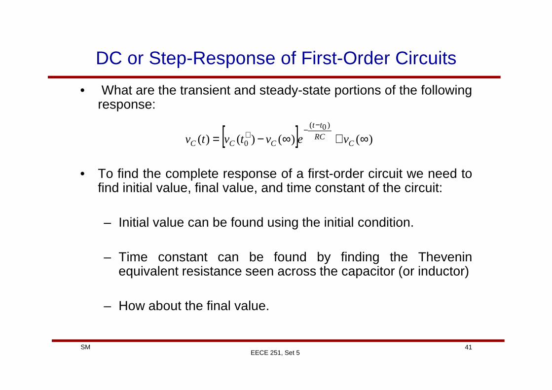
• What are the transient and steady-state portions of the followingresponse:
• To find the complete response of a first-order circuit we need tofind initial value, final value, and time constant of the circuit:
[ ] )()()()()0(
0 ∞+∞−=−
−+C
RC
tt
CCC vevtvtv
41SMEECE 251, Set 5
– Initial value can be found using the initial condition.
– Time constant can be found by finding the Theveninequivalent resistance seen across the capacitor (or inductor)
– How about the final value.
DC or Step-Response of First-Order Circuits
• Couple of interesting points (tricks) that are only valid forcalculating final values of DC step-response:
– A capacitor acts like a open circuit long time after theexternal excitation is applied. Can you intuitively justify thisstatement?
42SMEECE 251, Set 5
– An inductor acts like a short circuit long time after theexternal excitation is applied. Why?

Example
• Find v(t) for t>0 in the following circuit. Assume the switch hasbeen open for a long time before it is closed at t=0.
t=0s
+
v(t)
-
0.5A
43SMEECE 251, Set 5

Example
• Find i(t) for t>0 in the following circuit. Assume the switch hasbeen open for a long time before it is closed at t=0.
t=10s
0.5Ai(t)
44SMEECE 251, Set 5

Second-Order Linear Circuits
• A linear second order circuit is characterized by a linear second-order differential equation
• Second-order circuits in general consist of sources, resistors,and equivalent of two energy storage elements.
• Often to solve the resulting second-order differential equations
45SMEECE 251, Set 5
• Often to solve the resulting second-order differential equationsone need to find the initial value of the desired variable (voltageor current) and the initial value of the derivative of the variable.
• For finding initial conditions, always start with variables thatcannot change abruptly (like what?).
• Finding the initial value for the derivatives could be tricky!

Example
• In the following circuit the switch has been closed for a long timeand it opens at t = 0. Find:
dt
dv
dt
divi
)0(,
)0(),0(),0(
++++ and
+
v
i
46SMEECE 251, Set 5
t=0sv
-

Source-Free RLC Circuits
• Develop two second-order differential equation (one in iL andone in vC) for the following circuit.
+
vC
-
iL
47SMEECE 251, Set 5
Answer:
0)(1)()(
0)(1)()(
2
2
2
2
=++=++ tvLCdt
tdv
L
R
dt
tvdti
LCdt
tdi
L
R
dt
tidC
CCL
LL and

Source-Free RLC Circuits
• Develop two second-order differential equation (one in iL andone in vC) for the following circuit.
+
vC
-iL
48SMEECE 251, Set 5
Answer:
0)(1)(1)(
0)(1)(1)(
2
2
2
2
=++=++ tvLCdt
tdv
RCdt
tvdti
LCdt
tdi
RCdt
tidC
CCL
LL and

Constant Coefficient Second-Order Differential Equation
• The general form of the second-order differential equation thatresults from a second-order circuit with DC sources is of theform:
• x(t) can be any voltage or current in the circuit
Ftcxdt
tdxb
dt
txd =++ )()()(
2
2
49SMEECE 251, Set 5
• F represents the dc excitation of the circuit. Without loss ofgenerality and for simplicity let’s assume that the excitation isapplied to the circuit at time 0.
• The general solution is of the form
Fn Xtxtx += )()(

Constant Coefficient Second-Order Differential Equation
• xn(t) is the response to the following equation (typically referredto as homogeneous equation which represents the source-freecircuit):
• X is a constant which represents the steady-state response of
0)()()(
2
2
=++ tcxdt
tdxb
dt
txd
50SMEECE 251, Set 5
• XF is a constant which represents the steady-state response ofthe circuit to the dc excitation. We have:
Why?c
FX F =
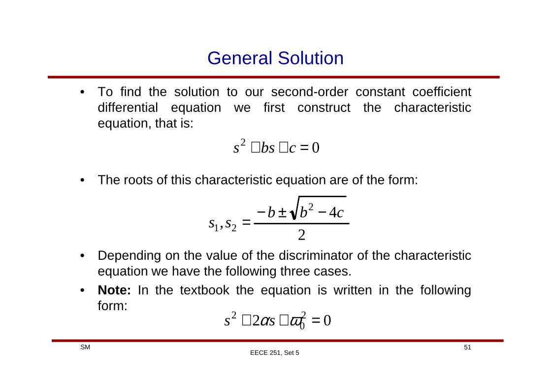
General Solution
• To find the solution to our second-order constant coefficientdifferential equation we first construct the characteristicequation, that is:
• The roots of this characteristic equation are of the form:
02 =++ cbss
51SMEECE 251, Set 5
• Depending on the value of the discriminator of the characteristicequation we have the following three cases.
• Note: In the textbook the equation is written in the followingform:
2
4,
2
21cbb
ss−±−=
02 20
2 =++ ωαss

Real and Distinct Roots (Overdamped Response)
• If the roots of the characteristic equation are realand distinct.
• The general form of the solution to the differential equation isthen:
042 >− cb
Ftsts
XeKeKtx ++= 22
11)(
52SMEECE 251, Set 5
where:
2211
21
)0(
)0(
KsKsdt
dx
XKKx
c
FX
F
F
+=
++=
=
+
+

Real and Equal Roots (Critically Damped Response)
• If the roots of the characteristic equation are realand equal.
• The general form of the solution to the differential equation isthen:
042 =− cb
Fts
XetKKtx ++= 121 )()(
53SMEECE 251, Set 5
where:
211
1
)0(
)0(
KKsdt
dx
XKx
c
FX
F
F
+=
+=
=
+
+

Complex Roots (Underdamped Response)
• If the roots of the characteristic equation arecomplex.
• In fact the roots are complex conjugate of each other and havethe form:
• The general form of the solution to the differential equation isthen:
042 <− cb
[ ]t ++= − ωωα
djss ωα ±−=21,
54SMEECE 251, Set 5
then:
where:
[ ] Fddt XtKtKetx ++= − )sin()cos()( 21 ωωα
21
1
)0(
)0(
KKdt
dx
XKx
c
FX
d
F
F
ωα +−=
+=
=
+
+
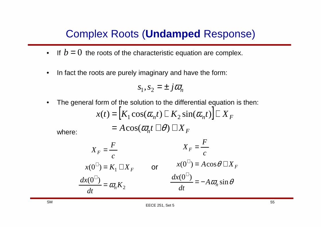
Complex Roots (Undamped Response)
• If the roots of the characteristic equation are complex.
• In fact the roots are purely imaginary and have the form:
• The general form of the solution to the differential equation is then:
0=b
[ ] XtKtKtx ++= )sin()cos()( ωω
njss ω±=21,
55SMEECE 251, Set 5
where:
[ ]Fn
Fnn
XtA
XtKtKtx
++=++=
)cos(
)sin()cos()( 21
θωωω
2
1
)0(
)0(
Kdt
dx
XKx
c
FX
n
F
F
ω=
+=
=
+
+
θω
θ
sin)0(
cos)0(
n
F
F
Adt
dx
XAx
c
FX
−=
+=
=
+
+or

Example
• In the following circuit, assume the switch is open for a longtime. Find v and i for t >0.
56SMEECE 251, Set 5
Related Documents