5 STC/MS ™ E LECTRICAL E NERGY AND C IRCUIT D ESIGN 61 OVERVIEW In this lesson, students begin their investigations of current electricity. In Lessons 2 and 3, which focused on static electricity, students saw that energy generated by static electricity could light a neon lightbulb briefly. Keeping a lightbulb lit continuously, however, requires a steady supply of electrical energy. Electrical circuits are a means of providing a steady supply of electrical energy to operate electrical devices. Lessons 5–12 are designed to develop students’ understandings of electrical circuits. Students investigate electrical current and voltage and how they are related in closed circuits. They also learn how to calculate the electrical power of a device and the electrical energy that a device uses when it is operated for a certain period of time. In this lesson, students use batteries, lightbulbs, and switches to build circuits that turn lightbulbs on and off in a variety of ways. In Inquiry 5.1, students build a simple circuit and identify the properties that make it a closed circuit. They also learn how to draw electrical diagrams, or schematics, for the circuits. In Inquiry 5.2, they build circuits in which they can turn lightbulbs on and off in different combinations. They draw schematics of these circuits and use their schematics to develop an understanding of series and parallel circuits. Electrical Circuits CONCEPTS (cont.) Switches are used to open and close paths in circuits. Schematic diagrams use symbols to represent the components of electrical devices and to show how these components are connected in electrical circuits. STUDENT OBJECTIVES Identify the components necessary for a closed circuit. Build electrical circuits in which a lightbulb or a combination of lightbulbs will light in prescribed ways. Draw schematics that represent electrical circuits. Identify the differences between series and parallel circuits. Use switches to turn lightbulbs on and off. Inquiries 2 Periods 3 CONCEPTS A closed path in an electrical circuit is one that can be traced in a continuous path from the source of electrical energy, around the circuit, and back to the energy source. An electrical circuit will transfer energy from the source to the user only if there is a closed path. A series circuit has only one closed path connecting the electrical components. Electrical components in series are on the same closed path; electrical components in series are on or off at the same time. A parallel circuit has more than one closed path connecting the electrical components. Electrical components in parallel are on separate closed paths; electrical components in parallel can simultaneously have one component turned on and another component turned off. LESSON BACKGROUND An electrical circuit is a system that enables electrical energy to be distributed to devices that transform the electrical energy into other forms of energy. The energy systems that students explored in Lesson 1 were all electrical circuits. Students found that each system had an electrical energy source and an electrical energy user. Each SAMPLE

Welcome message from author
This document is posted to help you gain knowledge. Please leave a comment to let me know what you think about it! Share it to your friends and learn new things together.
Transcript

5
STC/MS™ EL E C T R I C A L EN E R G Y A N D CI R C U I T DE S I G N 61
OVERVIEWIn this lesson, students begin their investigationsof current electricity. In Lessons 2 and 3, whichfocused on static electricity, students saw thatenergy generated by static electricity could light a neon lightbulb briefly. Keeping a lightbulb litcontinuously, however, requires a steady supplyof electrical energy. Electrical circuits are a meansof providing a steady supply of electrical energyto operate electrical devices. Lessons 5–12 aredesigned to develop students’ understandings ofelectrical circuits. Students investigate electricalcurrent and voltage and how they are related inclosed circuits. They also learn how to calculatethe electrical power of a device and the electricalenergy that a device uses when it is operated fora certain period of time.
In this lesson, students use batteries, lightbulbs,and switches to build circuits that turn lightbulbson and off in a variety of ways. In Inquiry 5.1,students build a simple circuit and identify theproperties that make it a closed circuit. They also learn how to draw electrical diagrams, orschematics, for the circuits. In Inquiry 5.2, theybuild circuits in which they can turn lightbulbson and off in different combinations. They drawschematics of these circuits and use theirschematics to develop an understanding ofseries and parallel circuits.
Electrical Circuits
CONCEPTS (cont.)
Switches are used to open and close paths incircuits.
Schematic diagrams usesymbols to represent thecomponents of electricaldevices and to show how these componentsare connected inelectrical circuits.
STUDENT OBJECTIVESIdentify the componentsnecessary for a closedcircuit.
Build electrical circuitsin which a lightbulb or acombination of lightbulbswill light in prescribedways.
Draw schematics thatrepresent electricalcircuits.
Identify the differencesbetween series andparallel circuits.
Use switches to turnlightbulbs on and off.
Inquiries 2Periods 3
CONCEPTSA closed path in anelectrical circuit is onethat can be traced in acontinuous path from the source of electricalenergy, around thecircuit, and back to theenergy source.
An electrical circuit willtransfer energy from thesource to the user only ifthere is a closed path.
A series circuit has only one closed pathconnecting the electricalcomponents.
Electrical components inseries are on the sameclosed path; electricalcomponents in series areon or off at the same time.
A parallel circuit hasmore than one closedpath connecting theelectrical components.
Electrical components inparallel are on separateclosed paths; electricalcomponents in parallelcan simultaneously haveone component turned onand another componentturned off.
LESSON
BACKGROUNDAn electrical circuit is a system that enables electrical energy to be distributed to devices thattransform the electrical energy into other formsof energy. The energy systems that studentsexplored in Lesson 1 were all electrical circuits.Students found that each system had an electricalenergy source and an electrical energy user. Each
SAMPLE
62 STC/MS™ EL E C T R I C A L EN E R G Y A N D CI R C U I T DE S I G N
LESSON 5 EL E C T R I C A L CI R C U I T S
Figure 5.2 Open circuit: With the switch open, there is a
broken path, resulting in no charge flow.
system also had wires or leadsthat connected the source tothe user. All electrical cir-cuits have the followingcomponents: an electricalenergy source, an elec-trical energy consumer,and a means to connectthe two. When thesource and the user areconnected in a continuousor unbroken path, chargeflows in the wires. This chargeflow, or current, provides the mech-anism to transport electrical energy from thesource to the user. A continuous charge flowenables a device to operate continuously.
Open and Closed CircuitsA continuous charge flow occurs if a circuit is closed. A closed circuit is one that hasan unbroken path for charge flow,as shown in Figure 5.1. Thismeans that, starting at theenergy source for the circuit,you can trace a continuous,unbroken path through the wiresand devices in the circuit andreturn to the energy source.
An open circuit has a gapor break in the path asyou move through thecircuit (see Figure 5.2).In open circuits, thereis no charge flow.Without the charge flow,electrical energy cannot betransported to the electricaldevices, so they cannot operate.
Figure 5.1 Closed circuit: With the switch closed, there
is a continuous path around the circuit, resulting in a
charge flow.
SAMPLE

STC/MS™ EL E C T R I C A L EN E R G Y A N D CI R C U I T DE S I G N 63
LESSON 5 EL E C T R I C A L CI R C U I T S
Figure 5.3 Two lightbulbs in series in a circuit
Switches are usually connected in series withdevices. Opening or closing a switch on a pathturns devices on and off because the switchstarts or stops the charge flow on the path. Forexample, in a typical home, you will find a wall switch in series with a ceiling light;opening and closing the switch turns the lighton and off.
SwitchesA switch is one device that is used to controlcircuits by controlling the flow of charge.Opening a switch creates a gap or break in thecircuit that stops the charge flow. Closing aswitch provides a continuous path that allowscharge to flow in the circuit.
Series CircuitsA series circuit is one that has only one closedpath that can be traced from the energy sourcethrough the devices in the circuit and back tothe source (see Figure 5.3). All devices in aseries circuit lie on the same path and have
the same charge flow through them. If severaldevices are connected together in a series cir-cuit and the charge flow is interrupted to onedevice, it is interrupted to all. Thus, devices ina series circuit are all on at the same time orall off at the same time.
SAMPLE
64 STC/MS™ EL E C T R I C A L EN E R G Y A N D CI R C U I T DE S I G N
LESSON 5 EL E C T R I C A L CI R C U I T S
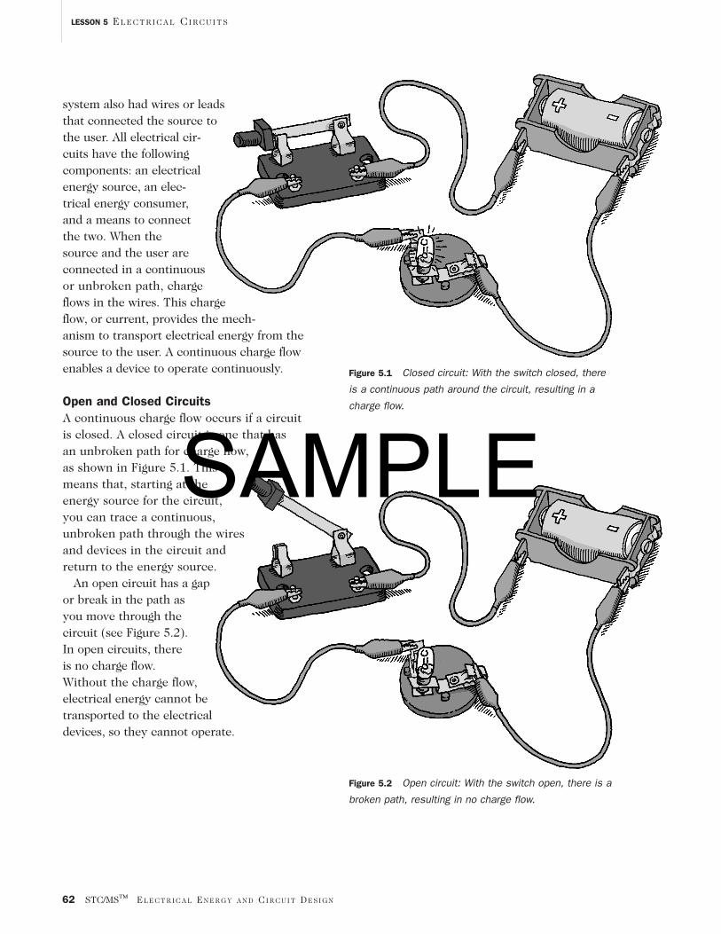
Parallel CircuitsA parallel circuit is onethat has more than oneclosed path connectingdevices to the energysource, as illustrated inFigure 5.4. Therefore, differentdevices can be connected to the energysource on different closed paths. Interruptingthe charge flow for one path does not inter-rupt it for other closed paths. Devicesconnected in parallel can operate inde-pendently of one another; that is, onedevice can be off, while other devices areon, since each has its own closed path tothe energy source. All homes contain parallelcircuits, which allow some lights or appliancesto be on while others are off.
Figure 5.5 Schematic for circuit with the switch closed,
as shown in the conventional drawing in Figure 5.1.
SchematicsSchematics are diagrams in which symbols repre-sent electrical components and their arrangementin circuits. A standard set of symbols representscomponents such as batteries, switches, light-bulbs, and so on. These symbols portray complexcircuits in an efficient way. Conventional drawingmethods are limited: They do not allow for aclear portrayal of all the components of suchdevices as a radio, nor do they show how adevice’s components are arranged to make acomplete circuit. Schematics simplify conven-tional drawings, which allows for easy identifi-cation of all of the components of a circuit. Inaddition, a schematic shows which items are inseries with each other, which are in parallel,and which other connections are needed tomake the circuit perform its desired function.Figures 5.5 and 5.6 show the schematics for,respectively, Figures 5.1 (circuit with closedswitch) and 5.2 (circuit with an open switch).
Figure 5.6 Schematic circuit with the switch open, as
shown in the conventional drawing in Figure 5.2.The electrical symbols chart, shown in SG
Figure 5.3 and TG Figure 5.17, shows the sym-bols for the electrical components used in thismodule. A poster of this chart is included inyour materials kit. Allow students to refer tothis chart as needed when drawing schematicsin future lessons.
Figure 5.4 Two lightbulbs connected in parallel in a circuitSAMPLE

Figure 5.8 How to securely connect wire leads to
a switch
STC/MS™ EL E C T R I C A L EN E R G Y A N D CI R C U I T DE S I G N 65
LESSON 5 EL E C T R I C A L CI R C U I T S
IMPLEMENTING LESSON 5This lesson requires three periods. Complete“Getting Started” and Inquiry 5.1 in the firstperiod and Inquiry 5.2 during the second. Usethe third period to discuss “Reflecting on WhatYou’ve Done” and the reading selections.
Getting StartedIn “Getting Started,” students examine theircircuit systems kit and identify its components. This gives them a chance to become familiar with and make an inventory of the kit’s contents. They should keep an inventory in their sciencenotebooks and update the inventory as they add additional components to the kit in succeedinglessons. Keeping an inventory aids in equipmentmanagement and provides a means of holding stu-dents accountable for the contents of their kits.
Students must have secure connections for theircircuits to function properly. SG Figures 5.1 and5.2 and TG Figures 5.7 and 5.8 show how to pro-duce the best connections by attaching wire leadsto the batteries and to the switches properly.
Figure 5.7 How to securely connect wire leads to
a battery
Inquiry 5.1In Inquiry 5.1, students build a simple circuitand draw in their science notebooks a picturethat shows the materials they used and the con-nections that make the lightbulb light. Expectstudents’ skill in building circuits to vary. Somewill bring prior experience with circuits to themodule; others will have to learn in class. Toturn the lightbulb off, students may disconnect awire from the lightbulb or battery, or they mayput a switch in the circuit, using it to open andclose the circuit. Both solutions are acceptablemeans of controlling the circuit and of turningthe lightbulbs on and off.
By examining other groups’ circuits, studentsshould recognize that each diagram makes a com-plete loop or closed path from the energy sourceto the lightbulb and back to the source. They canthen use these observations to write, in their ownwords, the definition of an electrical circuit.
Initially, students are asked to draw a pictureof their circuit and its components. When stu-dents discover how time consuming this step is,they should see the time-saving value of electricaldiagrams, or schematics. After they read aboutschematics, they can learn to use symbols to represent the components in their drawings.Working with the schematics helps studentsdevelop an appreciation for the value of symbols,allowing them to simplify their diagrams andcommunicate information more efficiently.
SAMPLE
66 STC/MS™ EL E C T R I C A L EN E R G Y A N D CI R C U I T DE S I G N
LESSON 5 EL E C T R I C A L CI R C U I T S
SAFETY TIP
Students should not screw the light-bulbs too tightly into the holders,which may cause the seal between the lightbulb globe and base to break.Students should turn the lightbulb gently until it makes contact with thebase of the holder.
Students are not given the definitions ofclosed and open circuits; instead, they areencouraged to construct a meaning for thesecircuits from their experiences with the circuitsin these inquiries. They should begin to realizethat the circuits must have a closed path for the lightbulbs to light. Likewise, they are notgiven definitions for series and parallel circuits;instead, they should analyze the circuits theybuilt. From their observations of how the light-bulbs can be turned on and off, they can beginto recognize that lightbulbs on the same path(series lightbulbs) must be both on or both offat the same time. They should see that lightbulbson separate closed paths (parallel lightbulbs) canbe on and off independently of one another. Theseparate closed paths in the circuit are calledparallel lines and the circuits with parallel linesare called parallel circuits.
Use the questions in “Reflecting on WhatYou’ve Done” to initiate a class discussion that focuses on what students have discoveredabout circuits in this lesson. Students are notasked to describe what they observe in termsof charge flow. They will investigate chargeflow in Lesson 6.
Inquiry 5.2In Inquiry 5.2, students explore how to connectbatteries, lightbulbs, and wires to make a set ofbulbs light in different combinations. They buildboth series and parallel circuits. Procedure Step 2in the Student Guide describes the different light-bulb combinations that students are to build.Students must figure out how to make the bulbslight as directed using only the equipment intheir circuit systems kit. Students turn a lightbulbon and off by using switches, unscrewing bulbs,or simply disconnecting a wire from a lightbulb.Allow students to use or try all of these methods.
SAMPLE
STC/MS™ EL E C T R I C A L EN E R G Y A N D CI R C U I T DE S I G N 67
LESSON 5 EL E C T R I C A L CI R C U I T S
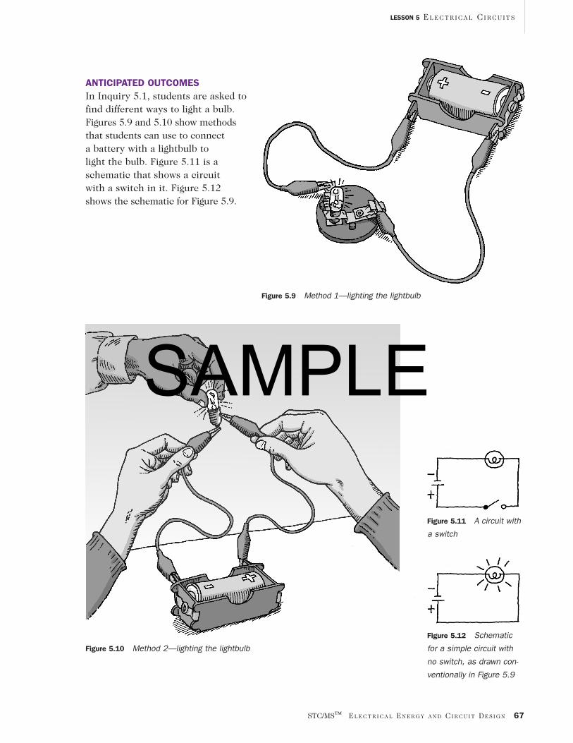
Figure 5.10 Method 2—lighting the lightbulb
ANTICIPATED OUTCOMESIn Inquiry 5.1, students are asked tofind different ways to light a bulb.Figures 5.9 and 5.10 show methodsthat students can use to connect a battery with a lightbulb tolight the bulb. Figure 5.11 is aschematic that shows a circuitwith a switch in it. Figure 5.12shows the schematic for Figure 5.9.
Figure 5.11 A circuit with
a switch
Figure 5.12 Schematic
for a simple circuit with
no switch, as drawn con-
ventionally in Figure 5.9
Figure 5.9 Method 1—lighting the lightbulb
SAMPLE

68 STC/MS™ EL E C T R I C A L EN E R G Y A N D CI R C U I T DE S I G N
LESSON 5 EL E C T R I C A L CI R C U I T S
Figures 5.13–5.16 show schematics for thestudent-built circuits in Inquiry 5.2. These circuit illustrations include switches. Studentsmay draw diagrams without switches if theychoose unscrewing the lightbulbs as theirmethod of turning them on and off.
Circuit A A circuit with two lightbulbs connected so thatboth must be on at the same time or both mustbe off at the same time
Figure 5.13 Schematic for Circuit A
Figure 5.14 Schematic for Circuit B
Circuit B A circuit with two lightbulbs connected so thatone lightbulb can be turned off but the otherlightbulb stays on
or
Circuit C A circuit with three lightbulbs connected sothat any one lightbulb can be turned off but theother two lightbulbs stay on
Figure 5.15 Schematic for Circuit C
or
Figure 5.16 Schematic for Circuit D
Circuit D A circuit with three lightbulbs connected sothat turning off one lightbulb turns off anotherlightbulb, but the third lightbulb stays on
or
SAMPLE

PREPARATION
1. Make sure students have adequate space attheir inquiry stations to set up the circuitsfor this lesson. They should have a cleartable surface so that they can set up theircircuits and clearly see the connections.
2. Put the materials for the circuit systemskits in the plastic boxes provided. Studentswill use these materials over the course ofseveral lessons, during which time they willadd other components to the boxes.
3. Designate a storage space where studentscan return their circuit systems kits at theend of the period or at the end of the day.
Getting Started
1. Distribute the circuit systems kits andhave students examine the contents ofeach box and identify each item using theequipment list. Remind them that theywill use this kit for many of the investiga-tions that follow.
2. Have students make a list of the kit’s com-ponents in their science notebooks and tellthem to leave room to add components tothese inventory lists in future lessons. Oryou can create one template inventory listof the kit’s components and make enoughcopies of the list for each group. To ensurethat their kits are complete when theystart a lesson, students can then check offevery component on the inventory listeach time they use the kit.
3. Have students look at Figures 5.1 and 5.2in the Student Guide. These illustrationsshow the best way to securely connectthe wire leads to the battery holders andswitches. Demonstrate, if necessary, howto use the alligator clips to attach thewires to the battery holders and switches.
READING SELECTIONSThree reading selections accompany this lesson.The background reader “Drawing ElectricalDiagrams” describes the advantages of usingschematic diagrams to show the components ofcircuits and how they are connected and intro-duces the standard symbols for most electricalcomponents. Students will not use all thesesymbols in this lesson, and they will not recog-nize some of the components for which symbolsappear. Inform them that they will learn aboutthese components as they progress through themodule. Assure them that they can refer to theelectrical symbols chart later, as needed.
“Electricity at Home: Safety Means ‘Don’tTouch!’” offers students guidelines for the safeuse of electricity in their homes. “Get Wired”explains household wiring and how it supplieselectrical current to appliances.
MATERIALS FOR LESSON 5
For the class1 Electrical Energy and Circuit Design poster
For each student1 copy of Student Sheet 5.2: Lighting
More Lightbulbs
For each group1 circuit systems kit
1 clear plastic box with lid3 D-cell batteries3 plastic D-cell battery holders1 pack of connector wires with alligator
clips (pack of 10)2 knife switches, single-pole/single-throw3 mini lightbulbs, 2.5 V3 mini bulb holders 1 electric buzzer
STC/MS™ EL E C T R I C A L EN E R G Y A N D CI R C U I T DE S I G N 69
LESSON 5 EL E C T R I C A L CI R C U I T S
SAMPLE

70 STC/MS™ EL E C T R I C A L EN E R G Y A N D CI R C U I T DE S I G N
LESSON 5 EL E C T R I C A L CI R C U I T S
Inquiry 5.1Lighting a Lightbulb
PROCEDURE
1. Challenge students to use the materials inthe circuit systems kit to build a circuitthat will light a single lightbulb.
2. Once they have succeeded in lighting thebulb, have students draw in their sciencenotebook a picture of their circuit thatshows how the components are connected.Students’ ability to draw the circuit willvary. Some will find it difficult to draw apicture of their circuit, while others withmore drawing ability may take time tomake a more detailed picture.
3. Have students discuss the following questions:
What one thing could you do to turn yourlightbulb off?
How would that change your drawing?
4. Visit each group and have them demon-strate for you what they would do to turnthe lightbulb off.
5. Encourage students to compare theirdrawings with those of other groups, andask them to list what is common to all.They should recognize that the drawingsshow the same components and thatwires connect the components to eachother. Some will notice that all the pathsare closed loops.
6. Have students write in their science notebooks their definition of the term“electrical circuit.” After they comparetheir definitions, encourage the class toreach agreement on what makes an elec-trical circuit.
7. Have students read “Drawing ElectricalDiagrams.” SAMPLE
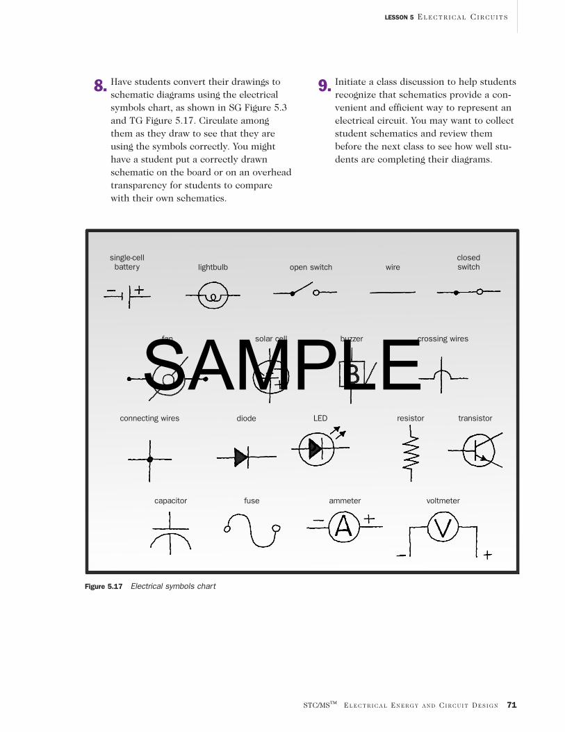
8. Have students convert their drawings toschematic diagrams using the electricalsymbols chart, as shown in SG Figure 5.3and TG Figure 5.17. Circulate amongthem as they draw to see that they areusing the symbols correctly. You mighthave a student put a correctly drawnschematic on the board or on an overheadtransparency for students to comparewith their own schematics.
Figure 5.17 Electrical symbols chart
single-cell battery lightbulb open switch wire
closed switch
fan solar cell buzzer crossing wires
connecting wires diode LED resistor transistor
capacitor fuse ammeter voltmeter
9. Initiate a class discussion to help studentsrecognize that schematics provide a con-venient and efficient way to represent anelectrical circuit. You may want to collectstudent schematics and review thembefore the next class to see how well stu-dents are completing their diagrams.
STC/MS™ EL E C T R I C A L EN E R G Y A N D CI R C U I T DE S I G N 71
LESSON 5 EL E C T R I C A L CI R C U I T S
SAMPLE
72 STC/MS™ EL E C T R I C A L EN E R G Y A N D CI R C U I T DE S I G N
LESSON 5 EL E C T R I C A L CI R C U I T S
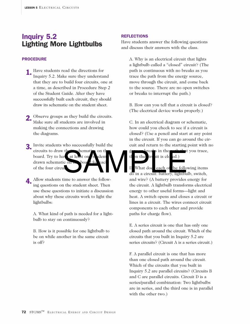
REFLECTIONSHave students answer the following questionsand discuss their answers with the class.
A. Why is an electrical circuit that lights a lightbulb called a “closed” circuit? (Thepath is continuous with no breaks as youtrace the path from the energy source,move through the circuit, and come back to the source. There are no open switchesor breaks to interrupt the path.)
B. How can you tell that a circuit is closed?(The electrical device works properly.)
C. In an electrical diagram or schematic,how could you check to see if a circuit isclosed? (Use a pencil and start at any pointin the circuit. If you can go around the cir-cuit and return to the starting point with nogaps or breaks in the path that you trace,then the circuit is closed.)
D. What does each of the following itemsdo in a circuit: battery, lightbulb, switch,and wire? (A battery provides energy forthe circuit. A lightbulb transforms electricalenergy to other useful forms—light andheat. A switch opens and closes a circuit orlines in a circuit. The wires connect circuitcomponents to each other and providepaths for charge flow).
E. A series circuit is one that has only oneclosed path around the circuit. Which of thecircuits that you built in Inquiry 5.2 areseries circuits? (Circuit A is a series circuit.)
F. A parallel circuit is one that has morethan one closed path around the circuit.Which of the circuits that you built inInquiry 5.2 are parallel circuits? (Circuits Band C are parallel circuits. Circuit D is aseries/parallel combination: Two lightbulbsare in series, and the third one is in parallelwith the other two.)
Inquiry 5.2Lighting More Lightbulbs
PROCEDURE
1. Have students read the directions forInquiry 5.2. Make sure they understandthat they are to build four circuits, one ata time, as described in Procedure Step 2of the Student Guide. After they have successfully built each circuit, they shoulddraw its schematic on the student sheet.
2. Observe groups as they build the circuits.Make sure all students are involved inmaking the connections and drawing the diagrams.
3. Invite students who successfully build thecircuits to draw their schematics on theboard. Try to have at least one student-drawn schematic on the board for each of the four circuits.
4. Allow students time to answer the follow-ing questions on the student sheet. Thenuse these questions to initiate a discussionabout why these circuits work to light thelightbulbs:
A. What kind of path is needed for a light-bulb to stay on continuously?
B. How is it possible for one lightbulb tobe on while another in the same circuit is off?
SAMPLE
ASSESSMENT
• Assess students’ understanding of circuit diagrams using the following criteria:
• Students’ pictures and diagrams include allcomponents (an electrical energy source,an electrical energy user, wires, switch).
• Students use correct symbols in theirschematics.
• Students’ pictures and schematics showproper connections that produce thedesired result.
• Assess students’ understanding, via their oral and written responses, of the followingconcepts:
• Closed circuits have a continuous paththat can be traced around the circuit.
• Series circuits have only one closed patharound the circuit.
• Components in series must be either both on at the same time or both off atthe same time.
• Parallel circuits have more than oneclosed path around the circuit.
• Components in parallel can be on and offindependently of one another.
• Switches control devices by opening andclosing paths.
HOMEWORK
Period 1Have students read “Electricity at Home: Safety Means ‘Don’t Touch!’”
Period 2Have students answer the questions on the student sheet and review the questions in“Reflecting on What You’ve Done” in prepara-tion for discussion in the next class.
EXTENSIONS
■ Technological Design
1. Have students use a computer circuit-simulation program to build electrical circuits.
■ Technological Design
2. Have students examine a blueprint for ahouse. Ask them to describe how a blue-print is like a schematic.
■ Technological Design
3. Have students read “Get Wired,” whichdescribes how houses are wired.
■ Technological Design
4. Have groups of students set up a workingcircuit of their own, and have them drawits schematic. Then have them exchangetheir schematic with another group. Havethat group build the circuit by referring tothe schematic and have the original groupcheck to see that they have built it cor-rectly and that it functions properly.
■ Technological Design
5. Give students a schematic of a circuit andhave them identify the components in the circuit as well as which componentsare in series and which components arein parallel.
STC/MS™ EL E C T R I C A L EN E R G Y A N D CI R C U I T DE S I G N 73
LESSON 5 EL E C T R I C A L CI R C U I T S
SAMPLE

SAMPLE
STC/MS™ EL E C T R I C A L EN E R G Y A N D CI R C U I T DE S I G N 75
LESSON 5 EL E C T R I C A L CI R C U I T S
Name:
Class: Date:
Student Sheet 5.2Lighting More Lightbulbs
Directions After building each circuit in Inquiry 5.2, draw a schematic for each circuit. Then answerthe questions that follow by examining your schematics.
Circuit A
Circuit B
© 2002 National Academy of Sciences
(continued)
SAMPLE
Student Sheet 5.2 (continued)
Circuit C
Circuit D
Examine your schematics to answer the following questions:
A. What kind of path is needed for a lightbulb to stay on continuously?
B. How is it possible for one lightbulb to be on while another in the same circuit is off?
LESSON 5 EL E C T R I C A L CI R C U I T S
76 STC/MS™ EL E C T R I C A L EN E R G Y A N D CI R C U I T DE S I G N © 2002 National Academy of Sciences
SAMPLE
Related Documents