EE40 Lec 3 Basic Circuit Analysis Prof. Nathan Cheung 09/03/2009 09/03/2009 Reading: Hambley Chapter 2 Slide 1 EE40 Fall 2009 Prof. Cheung

Welcome message from author
This document is posted to help you gain knowledge. Please leave a comment to let me know what you think about it! Share it to your friends and learn new things together.
Transcript

EE40
Lec 3
Basic Circuit Analysis
Prof. Nathan Cheung09/03/200909/03/2009
Reading: Hambley Chapter 2
Slide 1EE40 Fall 2009 Prof. Cheung
Chapter 2
• Outline– Resistors in Series – Voltage Divider– Conductances in Parallel – Current Divider– Node-Voltage Analysisg y– Mesh-Current Analysis– SuperpositionSuperposition– Thévenin equivalent circuits– Norton equivalent circuitsNorton equivalent circuits– Maximum Power Transfer
Slide 2EE40 Fall 2009 Prof. Cheung
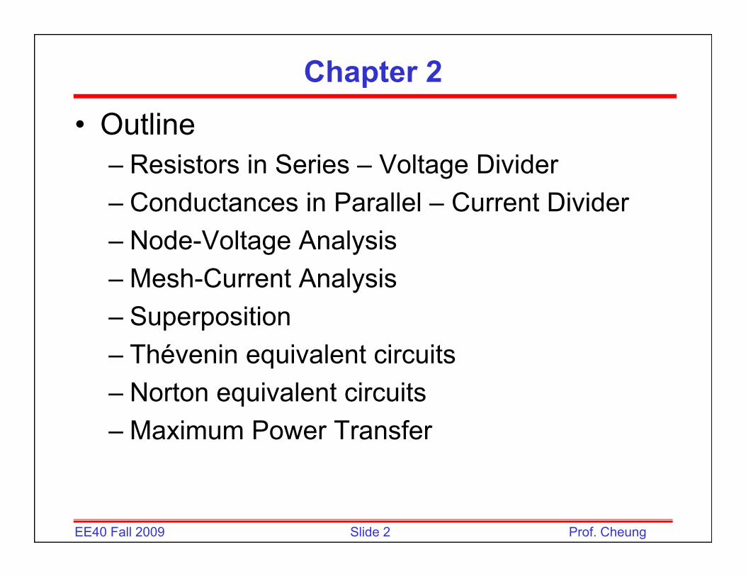
Voltage Divider
Slide 3EE40 Fall 2009 Prof. Cheung

Resistors in Series
• Resistors in seriesResistors in series can be combined into one equivalent resistance:
Slide 4EE40 Fall 2009 Prof. Cheung

Current Divider
Slide 5EE40 Fall 2009 Prof. Cheung
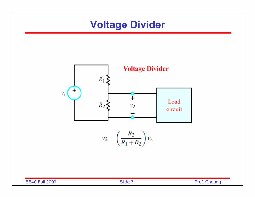
Resistors in Parallel
• Resistors in parallelResistors in parallel can be combined into one equivalent resistance:
Conductance G = 1/( Resistance R)
Slide 6EE40 Fall 2009 Prof. Cheung
[ unit = Siemens = 1/ohm]

Example Calculation with Series and Parallel Resistance
D t i V I I d I• Determine V2, I1, I2, and I3:
• From (c):( )
and A2210
24I1 =+
=
• Returning to (b):V422I2V 12 =×==
4V A33.134
3VI 2
2 ===
A67.04VI 23 ===
Slide 7EE40 Fall 2009 Prof. Cheung
A67.066
I3
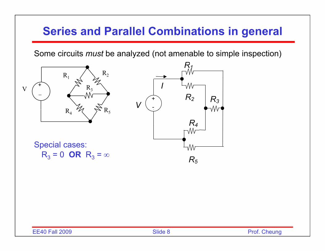
Series and Parallel Combinations in general
Some circuits must be analyzed (not amenable to simple inspection)R1
R1R2
-+ R2
V
IR3
1
−
+
R R
V R3
R4
R4 R5
R5
Special cases:R3 = 0 OR R3 = ∞
Slide 8EE40 Fall 2009 Prof. Cheung
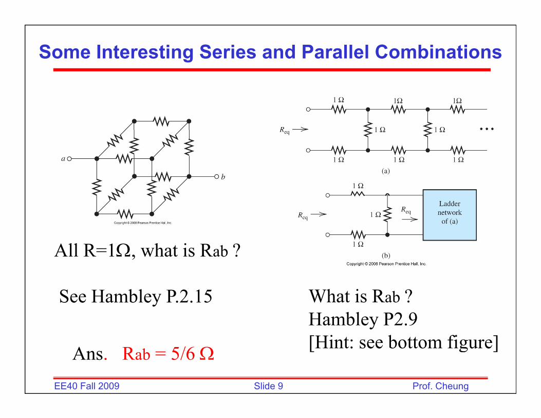
Some Interesting Series and Parallel Combinations
All R=1Ω, what is Rab ?
See Hambley P.2.15 What is Rab ?Hambley P2.9[Hint: see bottom figure]
Slide 9EE40 Fall 2009 Prof. Cheung
[Hint: see bottom figure]Ans. Rab = 5/6 Ω
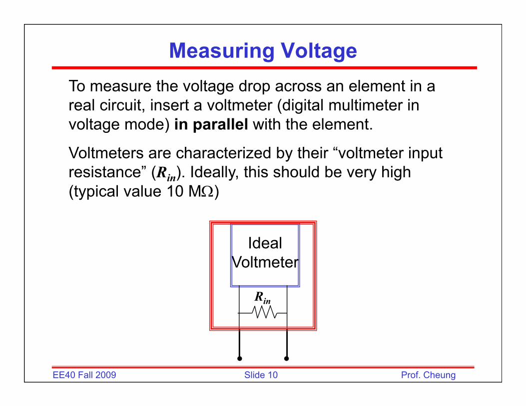
Measuring VoltageTo measure the voltage drop across an element in a real circuit, insert a voltmeter (digital multimeter in voltage mode) in parallel with the elementvoltage mode) in parallel with the element.
Voltmeters are characterized by their “voltmeter input resistance” (Rin). Ideally, this should be very high ( in) y, y g(typical value 10 MΩ)
Ideal Voltmeter
Rin
Slide 10EE40 Fall 2009 Prof. Cheung

Effect of Voltmeterundisturbed circuit circuit with voltmeter inserted
VSS
R1
R2_+
+V2 VSS
R1
R2 R_++V2′R2
–V2 SS R2 Rin
–V2
Compare to R2
+
=21
2SS2 RR
RVV
+
=′1in2
in2SS2 RR||R
R||RVV
Compare to R2
21 1in2 ||
Example: V1VK900R,K100R,V10V 212SS =⇒===
Slide 11EE40 Fall 2009 Prof. Cheung
210 , ?inR M V ′= =
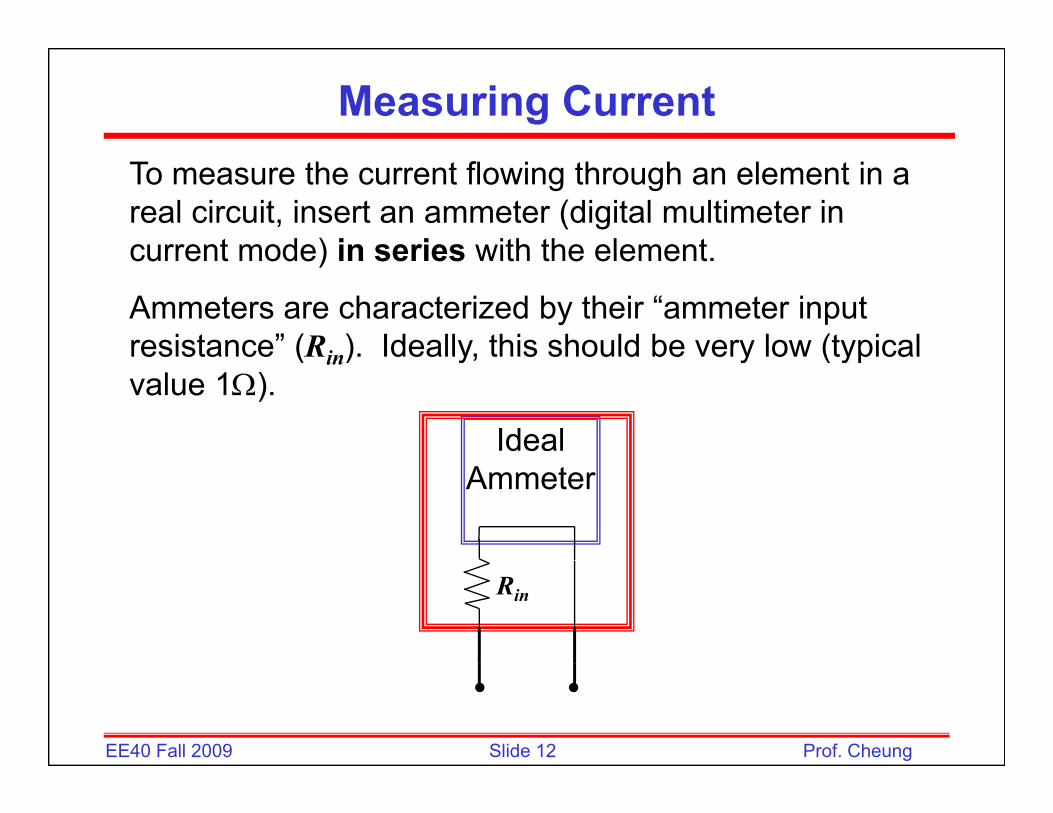
Measuring CurrentTo measure the current flowing through an element in a real circuit, insert an ammeter (digital multimeter in current mode) in series with the elementcurrent mode) in series with the element.
Ammeters are characterized by their “ammeter input resistance” (Rin). Ideally, this should be very low (typicalresistance (Rin). Ideally, this should be very low (typical value 1Ω).
Ideal Ammeter
Rin
Slide 12EE40 Fall 2009 Prof. Cheung

Effect of Ammeter
Icircuit with ammeter insertedundisturbed circuit
Measurement error due to non-zero input resistance:
R
Imeas
R1
ammeterI
R1Rin
V1R2
_+V1
R2
_+
1VI = 1meas
VI =
Example: V1 = 1 V, R1= R2 = 500 Ω, Rin = 1Ω
21 RRI
+ in21meas RRR ++
1VCompare to
Slide 13EE40 Fall 2009 Prof. Cheung
1 1 , ?500 500 meas
VI mA I= = =Ω+ Ω
R2 + R2

Source Combinations
• Voltage sources in • Current sources inVoltage sources in series can be replaced by an
Current sources in parallel can be replaced by an
equivalent voltage source:
equivalent current source:
–+
v1≡
+
+ i i ≡ i +i
–+
v2≡ –
+
v1+v2 i1 i2 ≡ i1+i2
Slide 14EE40 Fall 2009 Prof. Cheung

Example
Slide 15EE40 Fall 2009 Prof. Cheung

Example
Slide 16EE40 Fall 2009 Prof. Cheung

Node-Voltage Circuit Analysis1 Id tif ll t di d l t f1. Identify all extraordinary nodes, select one of
them as a reference node (ground), and then assign node voltages to the remaining (nex – 1) g g g ( ex )extraordinary nodes.
(Look for the one with the most connections)
2. At each of the (nex – 1) extraordinary nodes, apply the form of KCL requiring the sum of allapply the form of KCL requiring the sum of all currents leaving a node to be zero.
3. Solve the (nex – 1) independent simultaneous ( ex ) pequations to determine the unknown node voltages.
Slide 17EE40 Fall 2009 Prof. Cheung
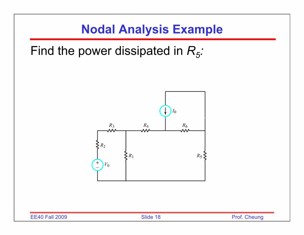
Nodal Analysis Example
Find the power dissipated in R5:
Slide 18EE40 Fall 2009 Prof. Cheung

Nodal Analysis Example
Step 1:
Slide 19EE40 Fall 2009 Prof. Cheung
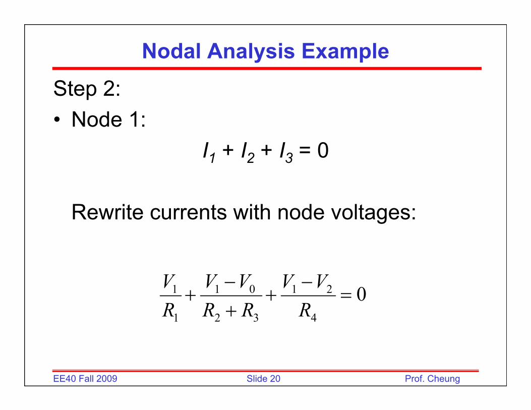
Nodal Analysis Example
Step 2:• Node 1:
I1 + I2 + I3 = 0
Rewrite currents with node voltages:
−− VVVVV 04
21
32
01
1
1 =−
++−
+RVV
RRVV
RV
Slide 20EE40 Fall 2009 Prof. Cheung

Nodal Analysis Example
• Node 2:I4 + I5 + I6 = 04 5 6
0320
12 =−
+−−
RVVI
RVV
64 RR
• Node 3:I7 + I8 + I9 = 07 8 9
00233 =+
−+ IVVV
Slide 21EE40 Fall 2009 Prof. Cheung
065 RR

Nodal Analysis Example
Step 3: Solve three simultaneous equations (Appendix B):
1111 V
32
02
41
4321
1111RR
VVR
VRRRR +
=
−
+
++
111 V
06
32
641
4
111 IRVV
RRV
R=−
++
−
0365
26
111 IVRR
VR
−=
++
−
Slide 22EE40 Fall 2009 Prof. Cheung
Solve for I7 = V3/R5; P = I72/R5
Node-Voltage Analysis: Dependent Sources
• Treat as independent source in organizing and writing node equations, but include another equation that expresses the relationship of the dependent source.
Slide 23EE40 Fall 2009 Prof. Cheung

Nodal Analysis with Dependent Sources
35 VVVVNode 1:
0634
3.5 2111 =−
++− VVVV
0126
212 =−+−
XIVVV
Node 2:
126
Dependant Source:( )( )
3622 2121 VVVVII X
−=
−==
Slide 24EE40 Fall 2009 Prof. Cheung
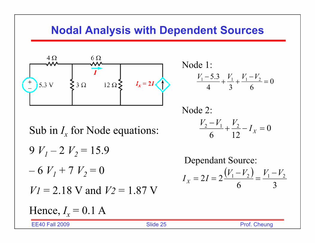
Nodal Analysis with Dependent Sources
35 VVVVNode 1:
0634
3.5 2111 =−
++− VVVV
0126
212 =−+−
XIVVV
Node 2:
Sub in Ix for Node equations: 126
Dependant Source:( )
9 V1 – 2 V2 = 15.9
6 V + 7 V 0 ( )36
22 2121 VVVVII X−
=−
==– 6 V1 + 7 V2 = 0
V1 = 2.18 V and V2 = 1.87 V
Slide 25EE40 Fall 2009 Prof. Cheung
Hence, Ix = 0.1 A
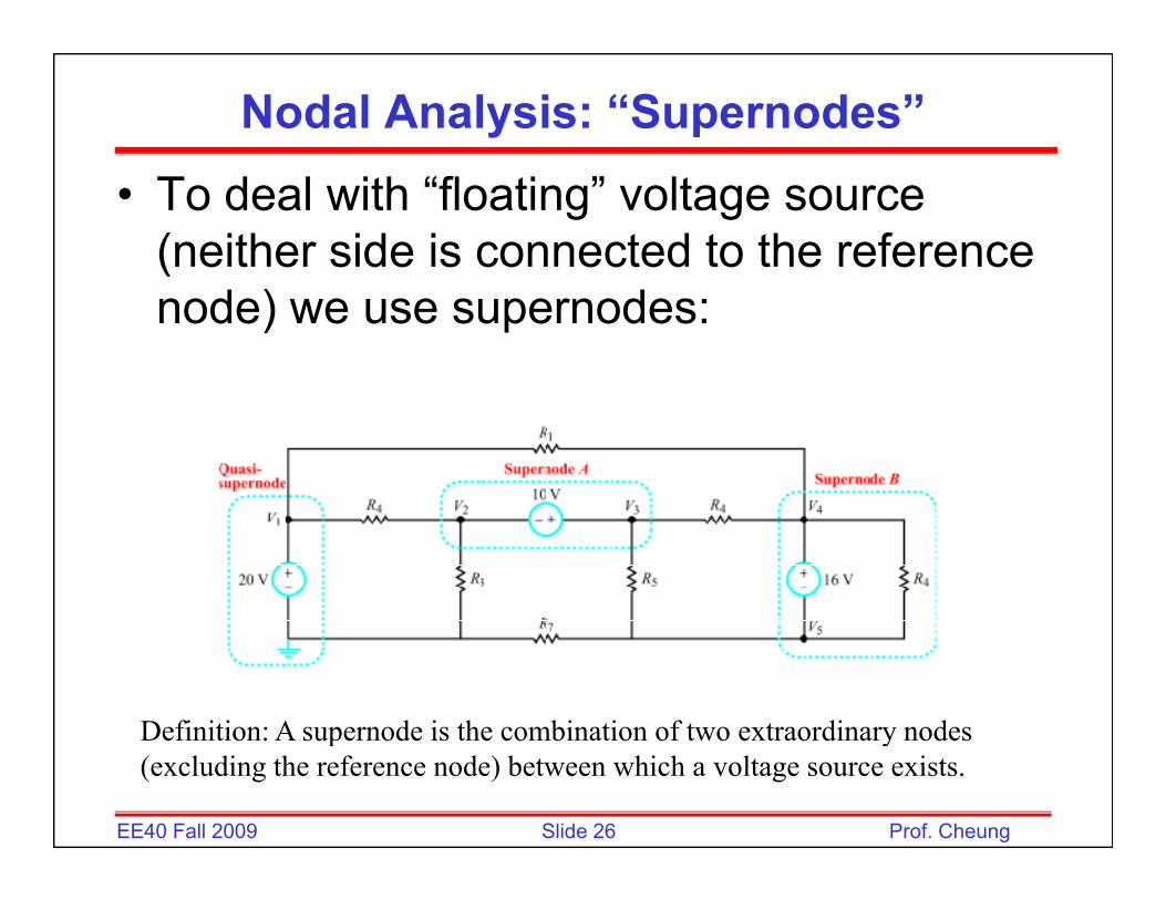
Nodal Analysis: “Supernodes”
• To deal with “floating” voltage source (neither side is connected to the reference node) we use supernodes:
Definition: A supernode is the combination of two extraordinary nodes
Slide 26EE40 Fall 2009 Prof. Cheung
Definition: A supernode is the combination of two extraordinary nodes (excluding the reference node) between which a voltage source exists.

Nodal Analysis: “Supernodes”
• To deal with “floating”To deal with floating voltage source (neither side is connected to the reference node) we
duse supernodes:
T i• Two equations:– KCL for supernode
A ili ti f
Slide 27EE40 Fall 2009 Prof. Cheung
– Auxiliary equation for voltages (KVL)

Supernode Example
• KCL @ supernode: • KVL @ supernode:0+++ IIII 18VV04321 =+++ IIII 1812 =−VV
02842
4 211 =−++− VVV
326 21 =+VV
842
Slide 28EE40 Fall 2009 Prof. Cheung
Solution: V1 = 2 V; V2 = 20 V
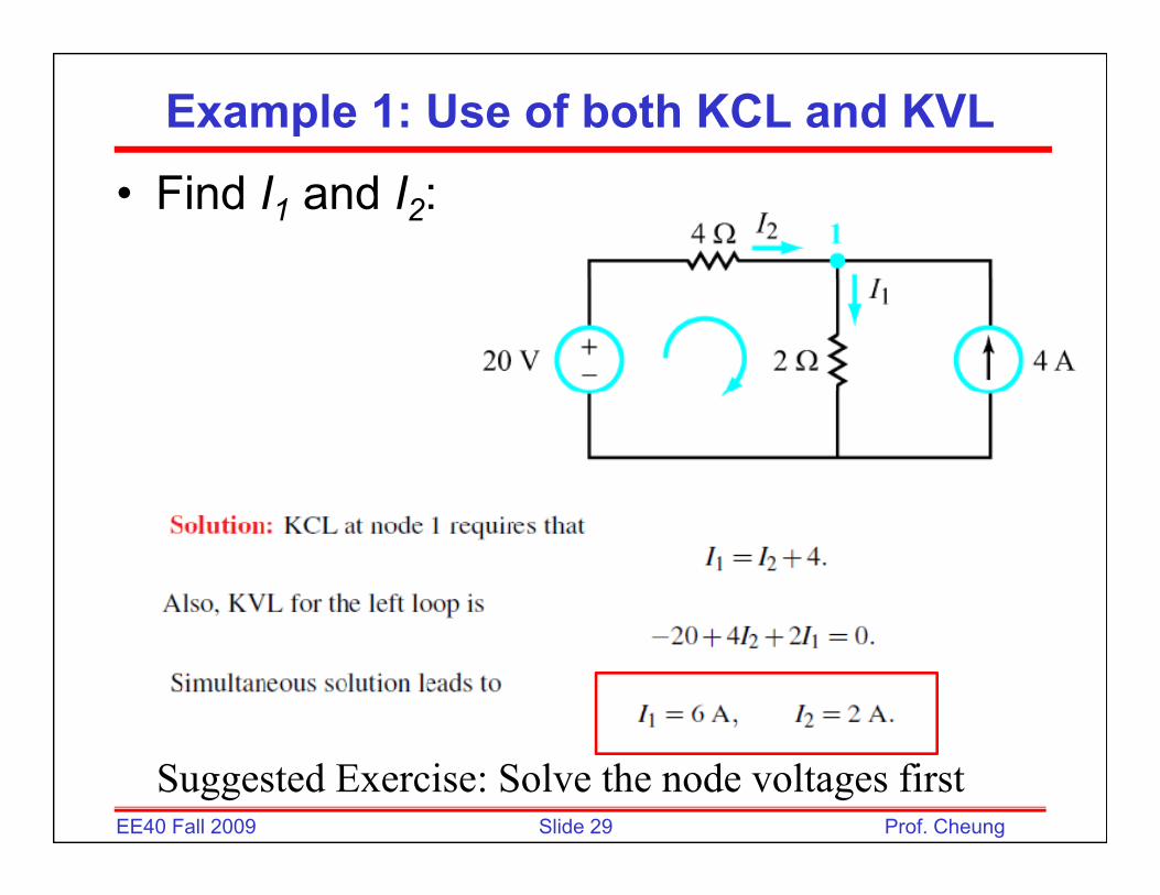
Example 1: Use of both KCL and KVL
• Find I1 and I2:
Slide 29EE40 Fall 2009 Prof. Cheung
Suggested Exercise: Solve the node voltages first
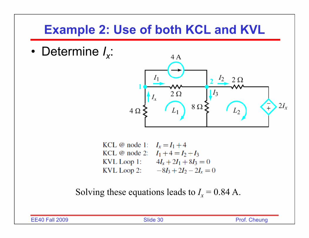
Example 2: Use of both KCL and KVL
• Determine Ix:
Solving these equations leads to I = 0.84 A.
Slide 30EE40 Fall 2009 Prof. Cheung
Solving these equations leads to Ix 0.84 A.
Related Documents