N.P.R COLLEGE OF ENGINEERING AND TECHNOLOGY NATHAM DEPARTMENT OF ELECTRICAL AND ELECTRONICS ENGG LECTURE NOTES Electric Energy Generation, Conservation and Utilization SUB CODE : EE1452 FACULTY NAME : R SATHISH KUMAR DESIGNATION : ASSISTANT PROFESSOR YEAR/SEM :IV/VIII ACADEMIC YEAR 2012-2013

Welcome message from author
This document is posted to help you gain knowledge. Please leave a comment to let me know what you think about it! Share it to your friends and learn new things together.
Transcript

N.P.R COLLEGE OF ENGINEERING AND TECHNOLOGY
NATHAM
DEPARTMENT OF ELECTRICAL AND ELECTRONICS ENGG
LECTURE NOTES
Electric Energy Generation, Conservation and Utilization
SUB CODE : EE1452
FACULTY NAME : R SATHISH KUMAR
DESIGNATION : ASSISTANT PROFESSOR
YEAR/SEM :IV/VIII
ACADEMIC YEAR 2012-2013

EE1452 – ELECTRIC ENERGY GENERATION, CONSERVATION AND UTILIZATION
L T P C
3 0 0 3
UNIT I GENERATION
Generation of electrical power by conventional methods: A brief review – Electrical systems in
Aircrafts and Ships – Distributed Generation (DG): Prospects and challenges – Effect of DG on
system operation.
UNIT II CONSERVATION 9
Economics of generation – Definitions – Load curves – Number and size of units – Cost of
electrical energy – Tariff – Need for electrical energy conservation – Methods – Energy efficient
equipment – Energy management – Energy auditing – Economics of power factor improvement
–Design for improvement of power factor using power capacitors – Power quality – Effect on
conservation.
UNIT III ILLUMINATION AND ELECTROLYTIC PROCESSES 9
Nature of radiation –Solid and Plane angle and its relation – Definition – Basic Laws
Photometry– Lighting Schemes – Lighting calculations – Design of illumination systems (for
residential,industrial, commercial, health care, street lighting, sports, administrative complexes)
– Types oflamps – Energy efficiency lamps – Design of choke and capacitor – Electrolytic
Process – Basicprinciples – Electro-deposition – Extraction and refining of metals methods –
Power supply for electrolytic processes.
UNIT IV ELECTRIC TRACTION 9
Basic concepts of electric Traction – Requirements of an ideal traction system – Supply systems
–Mechanics of train movement – Traction motors and control – Multiple units – Braking –
Current collection systems – Recent trends in electric traction.
UNIT V ELECTRIC HEATING AND WELDING 9
Introduction – Methods of heating – requirement of heating material – Design of heating element
–Electric Arc Furnaces – Induction Heating – Dielectric Heating – Electric Welding –Types of
Resistance welding – Welding transformer and its characteristics – Thyristorised Control circuit
of welding – Energy storage system for welding.
Total: 45
TEXT BOOKS
1. Uppal, S.L. and Rao, S., “Electrical Power Systems”, Khanna Publishers, 2009.
2. Wadhwa, C.L., “Generation, Distribution and Utilization of Electrical Energy”, New Age
International (P) Ltd, 2003.
REFERENCES
1. Partab, H., “Art and Science of Utilisation of Electrical Energy”, Dhanpat Rai and Co,
2004.
2. Gupta, B.R., “Generation of Electrical Energy”, Eurasia Publishing House (P) Ltd, 2003.
3. Rao, S., “Testing Commissioning Operation and Maintenance of Electrical Equipments”,
Khanna Publishers, 2007.

4. Anne Marie Borbely, Anne Marie Borbely, Jan F. Kreider., “Distributed Generation: The
Power Paradigm for the New Millenium”, CRC Press, 2001
UNIT –I
GENERATION
1. Introduction
In this lesson a brief idea of a modern power system is outlined. Emphasis is given to create a clear
mental picture of a power system to a beginner of the course Electrical Technology. As consumers,
we use electricity for various purposes such as:
1. Lighting, heating, cooling and other domestic electrical appliances used in home.
2. Street lighting, flood lighting of sporting arena, office building lighting, powering PCs etc.
3. Irrigating vast agricultural lands using pumps and operating cold storages for various
agricultural products.
4. Running motors, furnaces of various kinds, in industries.
5. Running locomotives (electric trains) of railways.
1.1 Basic idea of generation
Prior to the discovery of Faraday‟s Laws of electromagnetic discussion, electrical power was
available from batteries with limited voltage and current levels. Although complicated in
construction, D.C generators were developed first to generate power in bulk. However, due to
limitation of the D.C machine to generate voltage beyond few hundred volts, it was not economical
to transmit large amount of power over a long distance. For a given amount of power, the current
magnitude (I = P/V), hence section of the copper conductor will be large. Thus generation,
transmission and distribution of d.c power were restricted to area of few kilometer radius with no
interconnections between generating plants. Therefore, area specific generating stations along with
its distribution networks had to be used.
2. Thermal, hydel & nuclear power stations
In this section we briefly outline the basics of the three most widely found generating stations –
thermal, hydel and nuclear plants in our country and elsewhere.
2.1 Thermal plant
We have seen in the previous section that to generate voltage at 50 Hz we have to run the generator
at some fixed rpm by some external agency. A turbine is used to rotate the generator. Turbine may be
of two types, namely steam turbine and water turbine. In a thermal power station coal is burnt to
produce steam which in turn, drives the steam turbine hence the generator (turbo set). In figure 2.2
the elementary features of a thermal power plant is shown.

In a thermal power plant coil is burnt to produce high temperature and high pressure steam in a
boiler. The steam is passed through a steam turbine to produce rotational motion. The generator,
mechanically coupled to the turbine, thus rotates producing electricity. Chemical energy stored in
coal after a couple of transformations produces electrical energy at the generator terminals as
depicted in the figure. Thus proximity of a generating station nearer to a coal reserve and water
sources will be most economical as the cost of transporting coal gets reduced. In our country coal is
available in abundance and naturally thermal power plants are most popular. However, these plants
pollute the atmosphere because of burning of coals.
Figure 2.1: Basic components of a thermal generating unit.
Stringent conditions (such as use of more chimney heights along with the compulsory use of
electrostatic precipitator) are put by regulatory authorities to see that the effects of pollution is
minimized. A large amount of ash is produced every day in a thermal plant and effective handling of
the ash adds to the running cost of the plant. Nonetheless 57% of the generation in out country is
from thermal plants. The speed of alternator used in thermal plants is 3000 rpm which means 2-pole
alternators are used in such plants.
2.2 Hydel plants In a hydel power station, water head is used to drive water turbine coupled to the generator. Water
head may be available in hilly region naturally in the form of water reservoir (lakes etc.) at the hill
tops. The potential energy of water can be used to drive the turbo generator set installed at the base of
the hills through piping called pen stock. Water head may also be created artificially by constructing
dams on a suitable river. In contrast to a thermal plant, hydel power plants are eco-friendly, neat and
clean as no fuel is to be burnt to produce electricity. While running cost of such plants are low, the
initial installation cost is rather high compared to a thermal plants due to massive civil construction
necessary. Also sites to be selected for such plants depend upon natural availability of water
reservoirs at hill tops or availability of suitable rivers for constructing dams. Water turbines generally
operate at low rpm, so number of poles of the alternator are high. For example a 20-pole alternator
the rpm of the turbine is only 300 rpm.

Figure 2.2: Basic components of a hydal generating unit.
2.3 Nuclear plants As coal reserve is not unlimited, there is natural threat to thermal power plants based on coal. It is
estimated that within next 30 to 40 years, coal reserve will exhaust if it is consumed at the present
rate. Nuclear power plants are thought to be the solution for bulk power generation. At present the
installed capacity of nuclear power plant is about 4300 MW and expected to expand further in our
country. The present day atomic power plants work on the principle of nuclear fission of 235
U. In the
natural uranium, 235
U constitutes only 0.72% and remaining parts is constituted by 99.27% of 238
U
and only about 0.05% of 234
U. The concentration of 235
U may be increased to 90% by gas diffusion
process to obtain enriched 235
U. When 235
U is bombarded by neutrons a lot of heat energy along with
additional neutrons are produced. These new neutrons further bombard 235
U producing more heat and
more neutrons. Thus a chain reaction sets up. However this reaction is allowed to take place in a
controlled manner inside a closed chamber called nuclear reactor. To ensure sustainable chain
reaction, moderator and control rods are used. Moderators such as heavy water (deuterium) or very
pure carbon 12
C are used to reduce the speed of neutrons. To control the number neutrons, control
rods made of cadmium or boron steel are inserted inside the reactor. The control rods can absorb
neutrons. If we want to decrease the number neutrons, the control rods are lowered down further and
vice versa. The heat generated inside the reactor is taken out of the chamber with the help of a
coolant such as liquid sodium or some gaseous fluids. The coolant gives up the heat to water in heat
exchanger to convert it to steam as shown in figure 2.4. The steam then drives the turbo set and the
exhaust steam from the turbine is cooled and fed back to the heat exchanger with the help of water
feed pump. Calculation shows that to produce 1000 MW of electrical power in coal based thermal

plant, about 6 × 10⁶
Kg of coal is to be burnt daily while for the same amount of power, only about
2.5 Kg of 235
U is to be used per day in a nuclear power stations.
Figure 2.3: Nuclear Power generating unit.
The initial investment required to install a nuclear power station is quite high but running cost is low.
Although, nuclear plants produce electricity without causing air pollution, it remains a dormant
source of radiation hazards due to leakage in the reactor. Also the used fuel rods are to be carefully
handled and disposed off as they still remain radioactive.
The reserve of 235
U is also limited and cannot last longer if its consumption continues at the present
rate. Naturally search for alternative fissionable material continues. For example, plutonium (239
Pu)
and (233
U) are fissionable. Although they are not directly available. Absorbing neutrons, 238
U gets
converted to fissionable plutonium 239
Pu in the atomic reactor described above. The used fuel rods
can be further processed to extract 239
Pu from it indirectly increasing the availability of fissionable
fuel. Effort is also on to convert thorium into fissionable 233
U. Incidentally, India has very large
reserve of thorium in the world.
Total approximate generation capacity and Contribution by thermal, hydel and nuclear generation in
our country are given below.
Electrical systems in Aircrafts and Ships:
The function of the aircraft electrical system is to generate, regulate and distribute
electrical power throughout the aircraft
New-generation aircraft rely heavily on electrical power because of the wide use of
electronic flight instrument systems

Electrical Power Uses
Aircraft electrical power is used to operate:
Aircraft Flight Instruments
Essential Systems
Passenger Services
Essential power is power that the aircraft needs to be able to continue safe operation
Passenger services power is the power that used for:
Cabin lighting
Operation of entertainment systems
Preparation of food
Power Used
Aircraft electrical components operate on many different voltages both AC and
DC
However, most of the systems use:
– 115 VAC @ 400 Hz
– 28 VDC
26 VAC is also used in some aircraft for lighting
Power Sources
There are several different power sources on large aircraft to be able to handle excessive
loads, for redundancy, and for emergency situations.
These power sources include:
– Engine driven AC generators
– Auxiliary Power Units
– External power
– Ram Air Turbines
Most often the APUs power is used while the aircraft is on the ground during
maintenance or for engine starting
However, most aircraft can use the APU while in flight as a backup power source
– One exception to this is the B272, which only allows APU operation in the
ground
External power may only be used with the aircraft on the ground
This system utilizes a Ground Power Unit (GPU) to provide AC power through an
external plug on the nose of the aircraft
GPUs may be either portable or stationary units

Distributed Generation:
What is Distributed Generation?
Distributed generation is an approach that employs small-scale technologies to produce
electricity close to the end users of power. DG technologies often consist of modular (and
sometimes renewable-energy) generators, and they offer a number of potential benefits. In many
cases, distributed generators can provide lower-cost electricity and higher power reliability and
security with fewer environmental consequences than can traditional power generators.
In contrast to the use of a few large-scale generating stations located far from load centers--the
approach used in the traditional electric power paradigm--DG systems employ numerous, but
small plants and can provide power onsite with little reliance on the distribution and transmission
grid. DG technologies yield power in capacities that range from a fraction of a kilowatt [kW] to
about 100 megawatts [MW]. Utility-scale generation units generate power in capacities that
often reach beyond 1,000 MW.
Some Examples of Distributed Generation Technologies:
Distributed generation takes place on two-levels: the local level and the end-point level. Local
level power generation plants often include renewable energy technologies that are site specific,
such as wind turbines, geothermal energy production, solar systems (photovoltaic and

combustion), and some hydro-thermal plants. These plants tend to be smaller and less centralized
than the traditional model plants. They also are frequently more energy and cost efficient and
more reliable. Since these local level DG producers often take into account the local context, the
usually produce less environmentally damaging or disrupting energy than the larger central
model plants.
Distributed generation–impact on the system operation:
Impact of DG on power system
• Power Quality - at each unit
– Starting and stopping
– Flicker from tower shadow effect
• Power balance - at large penetration
– Non dispatchable, ”must run” units
– Uncontrolled, negative loads
– Wind power production hard to predict
• Protection - of network and units
Distributed Generation Advantages:
• Size for Base load Capacity to Meet
Minimum Constant Loads
• Capture Intermittent and Peaking Loads
in Residential and Commercial Cogeneration
• Increased Energy Efficiency
• Reduced Emissions

UNIT –2
CONSERVATION
Economics of Power Generation:
Introduction to Economics of Power Generation:
The function of a power station is to deliver power at the lowest possible cost per kilo watt hour.
This total cost is made up of fixed charges consisting of interest on the capital, taxes, insurance,
depreciation and salary of managerial staff, the operating expenses such as cost of fuels, water,
oil, labor, repairs and maintenance etc.
The cost of power generation can be minimized by :
1. Choosing equipment that is available for operation during the largest possible % of time in a
year.
2. Reducing the amount of investment in the plant.
3. Operation through fewer men.
4. Having uniform design
5. Selecting the station as to reduce cost of fuel, labor, etc.
All the electrical energy generated in a power station must be consumed immediately as it cannot
be stored. So the electrical energy generated in a power station must be regulated according to
the demand. The demand of electrical energy or load will also vary with the time and a power
station must be capable of meeting the maximum load at any time. Certain definitions related to
power station practice are given below:
Load curve :
Load curve is plot of load in kilowatts versus time usually for a day or a year.
Load duration curve :
Load duration curve is the plot of load in kilowatts versus time duration for which it occurs.

Maximum demand :
Maximum demand is the greatest of all demands which have occurred during a given period of
time.
Average load :
Average load is is the average load on the power station in a given period (day/month or year)
Base load :
Base load is the minimum load over a given period of time.
Connected load :
Connected load of a system is the sum of the continuous ratings of the load consuming apparatus
connected to the system.
Peak load :
Peak load is the maximum load consumed or produced by a unit or group of units in a stated
period of time. It may be the maximum instantaneous load or the maximum average load over a
designated interval of time.
Demand factor :
Demand factor is the ratio of maximum demand to the connected load of a consumer.
Diversity factor :
Diversity factor is the ratio of sum of individual maximum demands to the combined maximum
demand on power stations
Load factor :
Load factor is the ratio of average load during a specified period to the maximum load occurring
during the period.
Load factor = Average Load / Maximum demand

Station load factor :
Station load factor is the ratio of net power generated to the net maximum demand on a power
station.
Plant factor :
Plant factor is the ratio of the average load on the plant for the period of time considered, to the
aggregate rating of the generating equipment installed in the plant.
Capacity factor :
Capacity factor is the ratio of the average load on the machine for a period of time considered, to
the rating of the machine.
Demand factor :
Demand factor is the ratio of maximum demand of system or part of system, to the total
connected load of the system, or part of system, under consideration.
LOAD CURVES:
Definition:
The curve showing the variation of load on the power station with respect to time.
Types of load curves:
Daily load curve–Load variations during the whole day
Monthly load curve–Load curve obtained from the daily load curve
Yearly load curve-Load curve obtained from the monthly load curve

Load Characteristics:
Connected load
Maximum demand
Average load
Load factor
Diversity factor
Plant capacity factor
Plant use factor
Load duration curve:
When the elements of a load curve are arranged in the order of descending magnitudes.
Cost of electrical energy:
Electric Energy is the source of energy for electrical appliances. Your computer, the cooling, and
the lighting at your home are all powered by electric energy. Can you imagine life without
electric energy? Do you even know how much it costs? Electric Energy is measured in kWh
(kilowatt-hour) or MWh (megawatt-hour). Power is equal to work done in respect to time, so
work equals power multiplied by time. Since work equals energy, electric energy would be
measured by a kilowatt-hour.
P = W/t
W = E = Pt
(1000W)(1h) = 1kWh

The cost of each kWh depends on your location and the company you use. In New York, the
average kWh costs 14.31 cents, but it can cost as high as 16.73 cents in Hawaii or as low as 5.81
cents in Kentucky. You're probably thinking that's not so expensive, but when it all adds up, the
number can become significant. Just look at your electric bill. An electric bill in New York can
come out to be $81.68, depending on which appliances are being used. But imagine your electric
bill when you're blasting your air conditioner. It can cost you a few hundred dollars. But you can
decrease that cost by using more of your fan in place of your air conditioner because a typical fan
would cost you in the teens rather than in the hundreds. This is mainly due to the amount of watts
used to power your electric appliances. An air conditioner can use up to a few thousand watts,
while a fan would only use a few hundred watts. If you want to keep your electric bill low,
substitute high watt appliances for low watt appliances.
Energy conservation:
Energy conservation refers to efforts made to reduce energy consumption. Energy conservation
can be achieved through increased efficient energy use, in conjunction with decreased energy
consumption and/or reduced consumption from conventional energy sources
Energy being an important element of the infrastructure sector has to be ensured its availability
on sustainable basis. On the other hand, the demand for energy is growing manifold and the
energy sources are becoming scarce and costlier. Among the various strategies to be evolved for
meeting energy demand, efficient use of energy and its conservation emerges out to be the least
cost option in any given strategies, apart from being environmentally benign.
The steps to create sustainable energy system begin with the wise use of resources; energy
efficiency is the mantra that leads to sustainable energy management.
Energy Demand And Supply
On the energy demand and supply side, India is facing severe shortages. 70% of the total
petroleum product demand is being met by imports, imposing a heavy burden on foreign
exchange. Country is also facing Peak power and average energy shortages of 12% and 7%
respectively. To provide power for all , additional capacity of 100,000 MW would be needed by
2012, requiring approximately Rs.8000 billion investment. Further, the per capita energy
consumption in India is too low as compared to developed countries, which is just 4% of USA
and 20% of the world average. The per capita consumption is targeted to grow to about 1000
kWh per year by 2012 , thus imposing extra demand on power system.
Importance Of Energy Conservation
In a scenario where India tries to accelerate its development process and cope with increasing
energy demands, conservation and energy efficiency measures are to play a central role in our
energy policy. A national movement for energy conservation can significantly reduce the need
for fresh investment in energy supply systems in coming years. It is imperative that all-out
efforts are made to realize this potential. Energy conservation is an objective to which all the

citizen in the country can contribute. Whether a household or a factory, a small shop or a large
commercial building, a farmer or a office worker, every user and producer of energy can and
must make this effort for his own benefit, as well as that of the nation.
Energy audit methodology
The methodology adopted for this audit was
Formation of audit groups for specific areas and end use
Visual inspection and data collection
Observations on the general condition of the facility and equipment and quantification
Identification / verification of energy consumption and other parameters by
measurements
Detailed calculations, analyses and assumptions
Validation
Potential energy saving opportunities
Implementation
Improving Power Factor
Adding power factor capacitors is generally the most economical way to improve a facility‟s
power factor to minimize a power factor penalty.
While the current through an inductive load lags the voltage, current to a capacitor leads the
voltage. Thus power factor capacitors serve as a leading reactive current generator to counter the
lagging reactive current in a system.
This action is explained in terms of the energy stored in capacitors and induction devices. As the
voltage in ac circuits varies sinusoidally, it alternately passes through zero-voltage points and
maximum voltage points. As the voltage passes through zero voltage and starts toward
maximum voltage the capacitor stores energy in its electrostatic field, and the induction device
gives up energy from its electromagnetic field. As the voltage passes through a maximum point
and starts to decrease, the capacitor gives up energy and the induction device stores energy.
Thus when a capacitor and an inductor are installed in the same circuit, there is an exchange of
magnetizing current between them with the power factor capacitor actually supplying the
magnetizing requirements of the induction device. The capacitor thus releases the energy source
(the utility) from the need to supply the magnetizing current.
Simply stated, power factor capacitors supply the magnetizing current required by motors at or
near the motor site, instead of from the utility .This frees up utility capacity to provide more real
power.

Power Quality Events
Transients:
Impulsive Transients
Oscillatory Transients
Short Duration Variation
Voltage Sags or Dips
Voltage Swells
Interruptions
Voltage Magnitude Step
Long Duration Variation
Undervoltages
Overvoltages
interruptions
What is power quality?
Power quality is simply the interaction of electrical power with electrical equipment. If electrical
equipment operates correctly and reliably without being damaged or stressed, we would say that
the electrical power is of good quality. On the other hand, if the electrical equipment
malfunctions, is unreliable, or is damaged during normal usage, we would suspect that the power
quality is poor.
As a general statement, any deviation from normal of a voltage source (either DC or AC) can be
classified as a power quality issue. Power quality issues can be very high-speed events such as
voltage impulses / transients, high frequency noise, waveshape faults, voltage swells and sags
and total power loss. Each type of electrical equipment will be affected differently by power
quality issues. By analyzing the electrical power and evaluating the equipment or load, we can
determine if a power quality problem exists. See Power Quality events for a more detailed
description of power quality problems.
We can verify the power quality by installing a special type of high-speed recording test
equipment to monitor the electrical power. This type of test equipment will provide information
used in evaluating if the electrical power is of sufficient quality to reliably operate the
equipment. The process is similar to a doctor using a heart monitor to record the electrical
signals for your heart. Monitoring will provide us with valuable data, however the data needs to
be interpreted and applied to the type of equipment being powered. Lets look at two examples of
interpreting data for a USA location (other countries use different voltages but the same principal
applies).

Example No. 1
A standard 100-watt light bulb requires 120 volts to produce the designed light output
(measured in lumens). If the voltage drops to 108 volts (-10%), the light bulb still works but puts
out less lumens and is dimmer. If the voltage is removed as during a power outage, the light goes
out. Either a low voltage or complete power outage does not damage the light bulb. If however
the voltage rises to 130 volts (+10%), the light bulb will produce more lumens than it was
intended to, causing overheating and stress to the filament wire. The bulb will fail much sooner
than its expected design life; therefore, we could conclude that as far as a standard light bulb is
concerned, a power quality issue that shortens bulb life is high voltage. We could also conclude
that low voltage or a power outage would cause the lumen output to vary, which effects the
intended use of the bulb.
Example No. 2.
A CRT or monitor for a personal computer uses a 120 volt AC power supply to convert the
incoming voltage to specific DC voltages required to run the monitor, these voltages include 5
VDC for logic circuits and high voltage DC to operate the cathode ray tube (CRT). If the
incoming voltage drops to 108 volts (-10%), the power supply is designed to draw more current
or amps to maintain the proper internal voltages needed to operate the monitor. As a result of the
higher current draw, the power supply runs hotter and internal components are stressed more.
Although the operator of the monitor does not notice a problem, the long term effect of running
on low voltage is reduced reliability and increased failures of the monitor. If the power drops
below the operating range of the power supply, the monitor will shut down. If the voltage goes
above 132 volts AC (+10%), the power supply will not be able to regulate the internal voltages
and internal components will be damaged from high voltage; therefore, we conclude that the
power quality requirements for the PC monitor are much higher than for a light bulb. Both high
and low voltage can cause premature failures. The economic issues are much greater for the PC
monitor in both replacement cost and utilization purposes.
The above examples can be applied to any electrical or electronic systems. It is the task of the
power quality consultant to determine if the power, grounding, and infrastructure of a facility is
inadequate to operate the technological equipment. Once this assessment is made steps can be
taken to remediate the problems. To use the physician example, the diagnosis has to be made
before the medicine is prescribed. Many clients are buying power quality medicine without a
proper diagnosis. This is both costly and many times ineffective.
Power quality is simply the interaction of electrical power with electrical equipment. If electrical
equipment operates correctly and reliably without being damaged or stressed, we would say that
the electrical power is of good quality. On the other hand, if the electrical equipment
malfunctions, is unreliable, or is damaged during normal usage, we would suspect that the power
quality is poor.
As a general statement, any deviation from normal of a voltage source (either DC or AC) can be
classified as a power quality issue. Power quality issues can be very high-speed events such as

voltage impulses / transients, high frequency noise, waveshape faults, voltage swells and sags
and total power loss.
Power Quality Events
Power quality problems have many names and descriptions. Surges, spikes, transients, blackouts,
noise, are some common descriptions given, but what do they mean? This section delves into
defining power quality issues and terminology.
Power quality issues can be divided into short duration, long duration, and continuous
categories. The computer industry has developed a qualification standard to categorize power
quality events. The most common standard is the CBEMA curve (Computer Business
Equipment Manufacturing Association).
What can cause power quality problems?
Typical problems include grounding and bonding problems, code violations and internally
generated power disturbances.
Other internal issues include powering different equipment from the same power source. Lets
take an example of a laser printer and a personal computer. Most of us would not think twice
about plugging the laser printer into the same power strip that runs the PC. We are more
concerned about the software and communication compatibility than the power capability;
however, some laser printers can generate neutral-ground voltage swells and line-neutral voltage
sags every minute or so. The long term effect to the PC may be power supply failure. We have
to be careful in how technology is installed and wired.
Most common Power Quality problems:
Voltage sag (or dip)
Description:
A decrease of the normal voltage level between 10 and 90% of the nominal rms voltage at the
power frequency, for durations of 0,5 cycle to 1 minute.
Causes:
Faults on the transmission or distribution network (most of the times on parallel feeders). Faults
in consumer‟s installation. Connection of heavy loads and start-up of large motors.
Consequences:
Malfunction of information technology equipment, namely microprocessor-based control
systems (PCs, PLCs, ASDs, etc) that may lead to a process stoppage. Tripping of contactors and
electromechanical relays. Disconnection and loss of efficiency in electric rotating machines.

Very short interruptions
Description:
Total interruption of electrical supply for duration from few milliseconds to one or two seconds.
Causes:
Mainly due to the opening and automatic reclosure of protection devices to decommission a
faulty section of the network. The main fault causes are insulation failure, lightning and insulator
flashover.
Consequences:
Tripping of protection devices, loss of information and malfunction of data processing
equipment. Stoppage of sensitive equipment, such as ASDs, PCs, PLCs, if they‟re not prepared
to deal with this situation.
Long interruptions
Description:
Total interruption of electrical supply for duration greater than 1 to 2 seconds
Causes:
Equipment failure in the power system network, storms and objects (trees, cars, etc) striking
lines or poles, fire, human error, bad coordination or failure of protection devices.
Consequences: Stoppage of all equipment.
Voltage swell

Description:
Momentary increase of the voltage, at the power frequency, outside the normal tolerances, with
duration of more than one cycle and typically less than a few seconds.
Causes:
Start/stop of heavy loads, badly dimensioned power sources, badly regulated transformers
(mainly during off-peak hours).
Consequences:
Data loss, flickering of lighting and screens, stoppage or damage of sensitive equipment, if the
voltage values are too high.
Harmonic distortion
Description:
Voltage or current waveforms assume non-sinusoidal shape. The waveform corresponds to the
sum of different sine-waves with different magnitude and phase, having frequencies that are
multiples of power-system frequency.
Causes:
Classic sources: electric machines working above the knee of the magnetization curve (magnetic
saturation), arc furnaces, welding machines, rectifiers, and DC brush motors. Modern sources:
all non-linear loads, such as power electronics equipment including ASDs, switched mode power
supplies, data processing equipment, high efficiency lighting.
Consequences:
Increased probability in occurrence of resonance, neutral overload in 3-phase systems,
overheating of all cables and equipment, loss of efficiency in electric machines, electromagnetic
interference with communication systems, errors in measures when using average reading
meters, nuisance tripping of thermal protections.
UNIT –3
ILLUMINATION AND ELECTROLYTIC PROCESSES
Radiation is a form of energy. There are two basic types of radiation. One kind is particulate
radiation, which involves tiny fast-moving particles that have both energy and mass. Particulate
radiation is primarily produced by disintegration of an unstable atom and includes Alpha and
Beta particles.
Alpha particles are high energy, large subatomic structures of protons and neutrons. They can
travel only a short distance and are stopped by a piece of paper or skin. Beta particles are fast
moving electrons. They are a fraction of the size of alpha particles, but can travel farther and are
more penetrating.
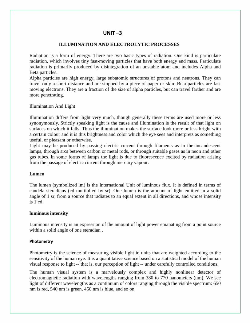
Illumination And Light:
Illumination differs from light very much, though generally these terms are used more or less
synonymously. Strictly speaking light is the cause and illumination is the result of that light on
surfaces on which it falls. Thus the illumination makes the surface look more or less bright with
a certain colour and it is this brightness and color which the eye sees and interprets as something
useful, or pleasant or otherwise.
Light may be produced by passing electric current through filaments as in the incandescent
lamps, through arcs between carbon or metal rods, or through suitable gases as in neon and other
gas tubes. In some forms of lamps the light is due to fluorescence excited by radiation arising
from the passage of electric current through mercury vapour.
Lumen
The lumen (symbolized lm) is the International Unit of luminous flux. It is defined in terms of
candela steradians (cd multiplied by sr). One lumen is the amount of light emitted in a solid
angle of 1 sr, from a source that radiates to an equal extent in all directions, and whose intensity
is 1 cd.
luminous intensity
Luminous intensity is an expression of the amount of light power emanating from a point source
within a solid angle of one steradian .
Photometry Photometry is the science of measuring visible light in units that are weighted according to the
sensitivity of the human eye. It is a quantitative science based on a statistical model of the human
visual response to light -- that is, our perception of light -- under carefully controlled conditions.
The human visual system is a marvelously complex and highly nonlinear detector of
electromagnetic radiation with wavelengths ranging from 380 to 770 nanometers (nm). We see
light of different wavelengths as a continuum of colors ranging through the visible spectrum: 650
nm is red, 540 nm is green, 450 nm is blue, and so on.

The sensitivity of the human eye to light varies with wavelength. A light source with a radiance
of one watt/m2
-steradian of green light, for example, appears much brighter than the same source
with a radiance of one watt/m2
-steradian of red or blue light. In photometry, we do not measure
watts of radiant energy. Rather, we attempt to measure the subjective impression produced by
stimulating the human eye-brain visual system with radiant energy.
This task is complicated immensely by the eye‟s nonlinear response to light. It varies not only
with wavelength but also with the amount of radiant flux, whether the light is constant or
flickering, the spatial complexity of the scene being perceived, the adaptation of the iris and
retina, the psychological and physiological state of the observer, and a host of other variables.
Nevertheless, the subjective impression of seeing can be quantified for “normal” viewing
conditions. In 1924, the Commission Internationale d‟Eclairage (International Commission on
Illumination, or CIE) asked over one hundred observers to visually match the “brightness” of
monochromatic light sources with different wavelengths under controlled conditions. The
statistical result -- the so-called CIE photometric curve shown ,the photopic luminous efficiency
of the human visual system as a function of wavelength. It provides a weighting function that can
be used to convert radiometric into photometric measurements.
Photometric theory does not address how we perceive colors. The light being measured can be
monochromatic or a combination or continuum of wavelengths; the eye‟s response is determined
by the CIE weighting function. This underlines a crucial point: The only difference between
radiometric and photometric theory is in their units of measurement. With this thought firmly in
mind, we can quickly review the fundamental concepts of photometry.
Luminous Flux (Luminous Power)
Luminous flux is photometrically weighted radiant flux (power). Its unit of measurement is the
lumen, defined as 1/683 watts of radiant power at a frequency of 540 x 1012
Hertz. As with
luminous intensity, the luminous flux of light with other wavelengths can be calculated using the
CIE photometric curve.
Luminous Energy

Luminous energy is photometrically weighted radiant energy. It is measured in lumen seconds.
Luminous Flux Density (Illuminance and Luminous Exitance)
Luminous flux density is photometrically weighted radiant flux density. Illuminance is the
photometric equivalent of irradiance, whereas luminous exitance is the photometric equivalent of
radiant exitance.
Luminous flux density is measured in lumens per square meter. (A footcandle is one lumen per
square foot.)
Lighting Calculations:
Inverse-square law
The skilled application of computerized point lighting calculations can optimize lighting levels in
both the task and ambient domains in order to minimize energy consumption. The lighting
professional should consider the use of point lighting calculations, both to design more energy-
efficient spaces, and to create spaces with more drama and visual interest.
Point calculations are an exceptionally accurate way to compare general lighting systems. While
the easier lumen method allows the comparison of average illuminance, point calculations permit
the comparison of uniformity of light on the work plane, the patterns of light produced on
ceilings and walls, and task contrast rendering. More specifically, point calculations allow
consideration of the effects listed below.
Effect on Room Surfaces. By evaluating the patterns of light on a wall caused by a row of
compact fluorescent down lights, an aesthetic evaluation can be made. Artwork locations
may be selected or lighting may be designed to highlight artwork. It may also be possible
to determine whether the pattern created on a wall will produce luminance extremes that
will cause glare or reflections in VDT screens.
Indirect Lighting Effects on Ceiling. When they are too close to the ceiling, indirect
lighting systems may create definite stripes or pools of light on the ceiling that are
distracting and that may image in VDT screens. Careful ceiling luminance calculations
can help identify the problem, and allow comparison of lighting products with various
optical distributions and suspension lengths to reduce the effect. Gray-scale printouts or
shaded VDT screen output of luminance make visual assessments possible.
Interior Task-Ambient Lighting. Point calculations should be used for any type of
lighting design where the task locations and types are well known and are unlikely to
move without a lighting redesign. They may also be used for lighting designs where tasks
that move end up in predefined locations.
Cautions for Point Calculations. In the case where a task light is used, or where an indirect
fixture is mounted within 12 inches of the ceiling, point calculations are not always appropriate.
In general, if the luminaire is close to the surface where lighting patterns are to be evaluated, a
near field situation exists. A shortcoming of the mathematics used in point calculations is that
these near field calculations are comparatively inaccurate unless near field photometric data is
available from the luminaire manufacturer, or the computer program is capable of adjusting the

characteristics of the luminaires to improve the accuracy of the results. Otherwise, it may be
more accurate to evaluate the light patterns from the task light or indirect fixture empirically.
The most common methods used for lighting calculations are:
(1) Watts Per Square Meter Method. This is principally a „rule of thumb‟ method very handy
for rough calculations or checking. It consists of making an allowance of watts/m2 of area
to be illuminated according to the illumination desired on the assumption of an average
figure of overall efficiency of the system.
(2) Lumen or Light Flux Method. This method is applicable to those cases where the sources
of light are such as to produce an approximate uniform illumination over the working
plane or where an average value is required. Lumens received on the working plane may
be determined from the relation.
Lumens received on the working plane = Number of lamps X wattage of each lamp X lamp
efficiency (lumens/watt) X coefficient of utilization/depreciation factor.
(3) Point-To-Point or Inverse Square Law Method. This method is applicable where the
illumination at a point due to one or more sources of light is required, the candle power of
sources in the particular direction under consideration being known. This method is not much
used because of its complicated and cumbersome applications.
Design of lighting system:
Direct lighting
Lighting provided from a source without reflection from other surfaces. In daylighting, this
means that the light has travelled on a straight path from the sky (or the sun) to the point of
interest. In electrical lighting it usually describes an installation of ceiling mounted or suspended
luminaires with mostly downward light distribution characteristics.
Indirect lighting
Lighting provided by reflection usually from wall or celiling surfaces. In daylighting, this means
that the light coming from the sky or the sun is reflected on a surface of high reflectivity like a
wall, a window sill or a special redirecting device. In electrical lighting the luminaires are
suspended from the ceiling or wall mounted and distribute light mainly upwards so it gets
reflected off the ceiling or the walls.
Types of Lighting
One of the primary functions of a luminaire is to direct the light to where it is needed. The light
distribution produced by luminaires is characterized by the Illuminating Engineering Society as
follows:

Direct Lighting ( 90 to 100 percent of the light is directed downward for maximum use.
Indirect Lighting( 90 to 100 percent of the light is directed to the ceilings and upper walls
and is reflected to all parts of a room.
Semi-Direct Lighting( 60 to 90 percent of the light is directed downward with the
remainder directed upward.
Semi-indirect Lighting ( 60 to 90 percent of the light is directed upward with the
remainder directed downward.
Highlighting Lighting( the beam projection distance and focusing ability characterize this
luminaire)
Types of lamps:
"Arc lamp" or "arc light" is the general term for a class of lamps that produce light by an electric arc (also called a voltaic arc). The lamp consists of two electrodes, first made from carbon but typically made today of tungsten, which are separated by a gas. The type of lamp is often named by the gas contained in the bulb; including neon, argon, xenon, krypton, sodium, metal halide, and mercury, or by the type of electrode as in carbon-arc lamps. The common fluorescent lamp is actually a low-pressure mercury arc lamp
High Pressure Mercury Vapour Lamp
The mercury vapour lamp in construction is similar to sodium vapour lamp. It gives greenish
blue colour light, which causes colour distortion. The efficiency is about 30-40 lumens per
watt. These lamps (MA type) are manufactured in 250 and 400 W ratings for use on 200-250 V
ac supply. Lamps of this type are used for general industrial lighting, railway yards, ports, work
areas; shopping centers etc where greenish-blue colour ligh is not objectionable. Another type,
which is manufactured in 300 and 500 W ratings for use on ac as well as dc supply mains is
MAT type. This is similar to MA type except that it does not use choke as ballast. Lower wattage
lamps, such as 80 and 125 W, are manufactured in a different design and using high vapour
pressure of about 5-10 atmospheres. These are known as MB type lamps.
Incandescent lamp:
The incandescent light bulb, incandescent lamp or incandescent light globe produces light by
heating a metal filament wire to a high temperature until it glows. The hot filament is protected
from oxidation in the air with a glass enclosure that is filled with inert gas or evacuated. In a
halogen lamp, filament evaporation is prevented by a chemical process that redeposits metal
vapor onto the filament, extending its life. The light bulb is supplied with electrical current by
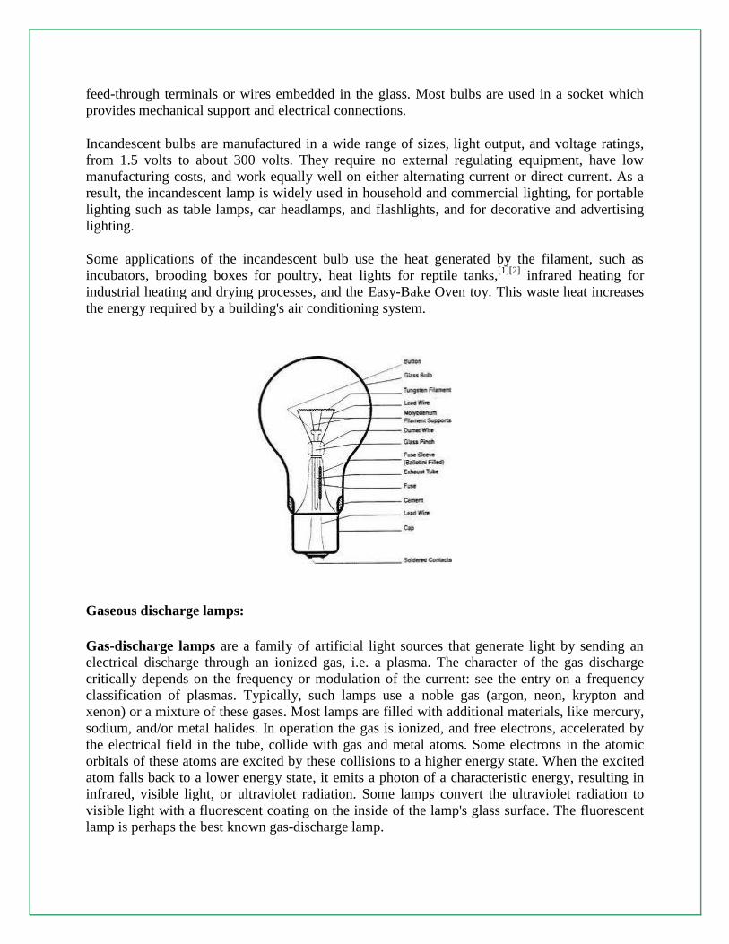
feed-through terminals or wires embedded in the glass. Most bulbs are used in a socket which
provides mechanical support and electrical connections.
Incandescent bulbs are manufactured in a wide range of sizes, light output, and voltage ratings,
from 1.5 volts to about 300 volts. They require no external regulating equipment, have low
manufacturing costs, and work equally well on either alternating current or direct current. As a
result, the incandescent lamp is widely used in household and commercial lighting, for portable
lighting such as table lamps, car headlamps, and flashlights, and for decorative and advertising
lighting.
Some applications of the incandescent bulb use the heat generated by the filament, such as
incubators, brooding boxes for poultry, heat lights for reptile tanks,[1][2]
infrared heating for
industrial heating and drying processes, and the Easy-Bake Oven toy. This waste heat increases
the energy required by a building's air conditioning system.
Gaseous discharge lamps:
Gas-discharge lamps are a family of artificial light sources that generate light by sending an
electrical discharge through an ionized gas, i.e. a plasma. The character of the gas discharge
critically depends on the frequency or modulation of the current: see the entry on a frequency
classification of plasmas. Typically, such lamps use a noble gas (argon, neon, krypton and
xenon) or a mixture of these gases. Most lamps are filled with additional materials, like mercury,
sodium, and/or metal halides. In operation the gas is ionized, and free electrons, accelerated by
the electrical field in the tube, collide with gas and metal atoms. Some electrons in the atomic
orbitals of these atoms are excited by these collisions to a higher energy state. When the excited
atom falls back to a lower energy state, it emits a photon of a characteristic energy, resulting in
infrared, visible light, or ultraviolet radiation. Some lamps convert the ultraviolet radiation to
visible light with a fluorescent coating on the inside of the lamp's glass surface. The fluorescent
lamp is perhaps the best known gas-discharge lamp.

Gas-discharge lamps offer long life and high efficiency, but are more complicated to
manufacture, and they require auxiliary electronic equipment such as ballasts to control current
flow through the gas. Due to their greater efficiency, gas-discharge lamps are replacing
incandescent lights in many lighting applications.
Sodium Vapour Lamp
Principally sodium vapour lamp consists of a bulb containing a small amount of metallic sodium,
neon gas and two sets of electrodes connected to a pin type base. The lamp operates at a
temperature of about 300°C and in order to conserve the heat generated and assure the lamp
operating at normal air temperatures the discharge envelope is enclosed in special vacuum
envelope designed for this purpose. The efficiency of a sodium vapour lamp under practical
conditions is about 40-50 lumens/watt. Such lamps are manufactured in 45,60,85 and 140 W
ratings. The average life is about 3000 hours and is not affected by voltage variations. The major
application of this type of lamp is for highway and general outdoor lighting where colour
discrimination is not required, such as street lighting, parks, rail yards, storage yards etc.
Energy Efficiency Techniques
Use of Day light, turn off the lights when not
required
Proper maintenance of lamps
Replacement with energy efficient lamps
Incorporate proper lighting controls
Use of electronic chokes instead of conventional
electromagnetic ballasts
Use of dimming controls
Electrolysis:
A means of producing chemical changes through reactions at electrodes in contact with an
electrolyte by the passage of an electric current. Electrolysis cells, also known as electrochemical
cells, generally consist of two electrodes connected to an external source of electricity (a power
supply or battery) and immersed in a liquid that can conduct electricity through the movement of
ions. Reactions occur at both electrode-solution interfaces because of the flow of electrons.
Reduction reactions, where substances add electrons, occur at the electrode called the cathode;
oxidation reactions, where species lose electrons, occur at the other electrode, the anode. In the
cell shown in the illustration, water is reduced at the cathode to produce hydrogen gas and
hydroxide ion; chloride ion is oxidized at the anode to generate chlorine gas. Electrodes are
typically constructed of metals (such as platinum or steel) or carbon. Electrolytes usually consist
of salts dissolved in either water or a nonaqueous solvent, or they are molten salts. See also
Electrochemistry; Electrode; Electrolyte; Oxidation-reduction.

The Electrolytic Process:
The electrolytic process requires that an electrolyte, an ionized solution or molten metallic salt,
complete an electric circuit between two electrodes. When the electrodes are connected to a
source of direct current one, called the cathode, becomes negatively (−) charged while the other,
called the anode, becomes positively (+) charged. The positive ions in the electrolyte will move
toward the cathode and the negatively charged ions toward the anode. This migration of ions
through the electrolyte constitutes the electric current in that part of the circuit. The migration of
electrons into the anode, through the wiring and an electric generator, and then back to the
cathode constitutes the current in the external circuit.
For example, when electrodes are dipped into a solution of hydrogen chloride (a compound of
hydrogen and chlorine) and a current is passed through it, hydrogen gas bubbles off at the
cathode and chlorine at the anode. This occurs because hydrogen chloride dissociates (see
dissociation) into hydrogen ions (hydrogen atoms that have lost an electron) and chloride ions
(chlorine atoms that have gained an electron) when dissolved in water. When the electrodes are
connected to a source of direct current, the hydrogen ions are attracted to the cathode, where they
each gain an electron, becoming hydrogen atoms again. Hydrogen atoms pair off into hydrogen
molecules that bubble off as hydrogen gas. Similarly, chlorine ions are attracted to the anode,
where they each give up an electron, become chlorine atoms, join in pairs, and bubble off as
chlorine gas.
The fact that electrical energy can produce chemical changes and the processes based on it,
called the „electrolytic processes‟ are widely used for the extraction of pure metals from their
ores (such as aluminum, zinc, copper, magnesium, sodium etc), refining of metals (such as gold,
silver, copper, nickel, lead, iron etc.), manufacturing of various chemicals such as caustic soda,
potassium permanganate, hydrogen, oxygen, chlorine etc), electro-deposition of metals including
electro-plating, electro-typing, electro-forming, building up of worn out parts in metallurgical,

chemical and other industries. Though the various processes mentioned are different in apparent
detail but fundamentally they are alike, being based on the principle of electrolysis. The mass of
chemical deposition due to flow of electric current I through the electrolyte for time t is given by
the expression
M = Zit
where Z is the electro-chemical equivalent of the substance in kg/coulomb.
Power supply required for electrolytic processes is direct current and at very low voltage. The
power required for electro-deposition is usually very small (say 100-200A at 10-12V). Power
supply required for extraction and refining of metals and large scale manufacture of chemicals is
in very large amounts.
Electroplating
In electroplating, the plating metal is generally the anode, and the object to be plated is the
cathode. A solution of a salt of the plating metal is the electrolyte. The plating metal is deposited
on the cathode, and the anode replenishes the supply of positive ions, thus gradually being
dissolved. Electrotype printing plates, silverware, and chrome automobile trim are plated by
electrolysis.
The English scientist Michael Faraday discovered that the amount of a material deposited on an
electrode is proportional to the amount of electricity used. The ratio of the amount of material
deposited in grams to the amount of electricity used is the electrochemical equivalent of the
material. Actual electric consumption may be as high as four times the theoretical consumption
because of such factors as heat loss and undesirable side reactions.
Electric Cells
An electric cell is an electrolytic system in which a chemical reaction causes a current to flow in
an external circuit; it essentially reverses electrolysis. A battery is a single electric cell (or two or
more such cells linked together for additional power) used as a source of electrical energy. Metal
corrosion can take place by electrolysis in an unintentionally created electric cell. The Italian
physicist Alessandro Volta discovered the principle of the electric cell. Within a few weeks
William Nicholson and Sir Anthony Carlisle, English scientists, performed the first electrolysis,
breaking water down into oxygen and hydrogen.

Process of electrolysis
The key process of electrolysis is the interchange of atoms and ions by the removal or addition of
electrons from the external circuit. The required products of electrolysis are in some different
physical state from the electrolyte and can be removed by some physical processes. For example,
in the electrolysis of brine to produce hydrogen and chlorine, the products are gaseous. These
gaseous products bubble from the electrolyte and are collected.
2 NaCl + 2 H2O → 2 NaOH + H2 + Cl2
A liquid containing mobile ions (electrolyte) is produced by
Solvation or reaction of an ionic compound with a solvent (such as water) to produce
mobile ions
An ionic compound is melted (fused) by heating
An electrical potential is applied across a pair of electrodes immersed in the electrolyte.
Each electrode attracts ions that are of the opposite charge. Positively charged ions (cations)
move towards the electron-providing (negative) cathode, whereas negatively charged ions
(anions) move towards the positive anode.
At the electrodes, electrons are absorbed or released by the atoms and ions. Those atoms that
gain or lose electrons to become charged ions pass into the electrolyte. Those ions that gain or
lose electrons to become uncharged atoms separate from the electrolyte. The formation of
uncharged atoms from ions is called discharging.
The energy required to cause the ions to migrate to the electrodes, and the energy to cause the
change in ionic state, is provided by the external source of electrical potential.
Oxidation and reduction at the electrodes
Oxidation of ions or neutral molecules occurs at the anode, and the reduction of ions or neutral
molecules occurs at the cathode. For example, it is possible to oxidize ferrous ions to ferric ions
at the anode:
Fe2+aq → Fe3+aq + e–
It is also possible to reduce ferricyanide ions to ferrocyanide ions at the cathode:
Fe(CN)3-6 + e– → Fe(CN)4-6
Neutral molecules can also react at either electrode. For example: p-Benzoquinone can be
reduced to hydroquinone at the cathode:

+ 2 e– + 2 H
+ →
In the last example, H+ ions (hydrogen ions) also take part in the reaction, and are provided by an
acid in the solution, or the solvent itself (water, methanol etc.). Electrolysis reactions involving
H+ ions are fairly common in acidic solutions. In alkaline water solutions, reactions involving
OH- (hydroxide ions) are common.
The substances oxidised or reduced can also be the solvent (usually water) or the electrodes. It is
possible to have electrolysis involving gases.
Energy changes during electrolysis
The amount of electrical energy that must be added equals the change in Gibbs free energy of the
reaction plus the losses in the system. The losses can (in theory) be arbitrarily close to zero, so
the maximum thermodynamic efficiency equals the enthalpy change divided by the free energy
change of the reaction. In most cases, the electric input is larger than the enthalpy change of the
reaction, so some energy is released in the form of heat. In some cases, for instance, in the
electrolysis of steam into hydrogen and oxygen at high temperature, the opposite is true. Heat is
absorbed from the surroundings, and the heating value of the produced hydrogen is higher than
the electric input.
Faraday's laws of electrolysis
First law of electrolysis
In 1832, Michael Faraday reported that the quantity of elements separated by passing an electric
current through a molten or dissolved salt is proportional to the quantity of electric charge passed
through the circuit. This became the basis of the first law of electrolysis:
Second law of electrolysis
Faraday also discovered that the mass of the resulting separated elements is directly proportional
to the atomic masses of the elements when an appropriate integral divisor is applied. This
provided strong evidence that discrete particles of matter exist as parts of the atoms of elements.
Electrolysis of water
One important use of electrolysis of water is to produce hydrogen.

2 H2O(l) → 2 H2(g) + O2(g); E0 = +1.229 V
Hydrogen can be used as a fuel for powering internal combustion engines by combustion or
electric motors via hydrogen fuel cells (see Hydrogen vehicle). This has been suggested as one
approach to shift economies of the world from the current state of almost complete dependence
upon hydrocarbons for energy (See hydrogen economy.)
The energy efficiency of water electrolysis varies widely. The efficiency is a measure of what
fraction of electrical energy used is actually contained within the hydrogen. Some of the
electrical energy is converted to heat, an almost useless byproduct. Some reports quote
efficiencies between 50% and 70% This efficiency is based on the Lower Heating Value of
Hydrogen. The Lower Heating Value of Hydrogen is total thermal energy released when
hydrogen is combusted minus the latent heat of vaporisation of the water. This does not represent
the total amount of energy within the hydrogen, hence the efficiency is lower than a more strict
definition. Other reports quote the theoretical maximum efficiency of electrolysis as being
between 80% and 94%.The theoretical maximum considers the total amount of energy absorbed
by both the hydrogen and oxygen. These values refer only to the efficiency of converting
electrical energy into hydrogen's chemical energy. The energy lost in generating the electricity is
not included. For instance, when considering a power plant that converts the heat of nuclear
reactions into hydrogen via electrolysis, the total efficiency is more likely to be between 25%
and 40%.
NREL found that a kilogram of hydrogen (roughly equivalent to a gallon of gasoline) could be
produced by wind powered electrolysis for between $5.55 in the near term and $2.27 in the long
term.
About four percent of hydrogen gas produced worldwide is created by electrolysis, and normally
used onsite. Hydrogen is used for the creation of ammonia for fertilizer via the Haber process,
and converting heavy petroleum sources to lighter fractions via hydro cracking.
Electro-Refining Operations
Copper anodes from the converter process are dissolved electrolytically using an acid copper
sulphate solution as an electrolyte. The products of this operation are pure copper cathodes and
an anode slime which may contain gold and small quantities of the platinum group metals. The
cells are constructed of rubber-lined concrete. Internal measurements are approximately 84 x2 x3
feet. The warmed electrolyte is fed in at one end and overflows from the other into a launder
running between the lines of cells. From the launder the liquid is pumped to overhead tanks
where its heat is maintained, and by gravity flows to a manifold which feeds it back to the cells.
During electrolysis the electrolyte tends to accumulate nickel and quantities have to be bled off
occasionally and replaced by pure copper sulphate. The impure electrolyte is treated for recovery
of the copper sulphate and the nickel sulphate is passed to the nickel refinery. There are 21
anodes and 20 cathodes in each cell and a current of 15; amp per square foot is maintained. The
quantity of anode slime formed by the dissolving of these anodes is small and falls to the bottom
of the cells, where it is periodically recovered. The dissolving of the nickel anodes follows the
same general pattern, the products being pure nickel cathodes and an anode slime containing the

bulk of the platinum group metals. In this case the electrolyte is a neutral solution of nickel
sulphate containing boric acid as a buffer and has to be continually purified to produce a pure
cathode. Copper and iron are present in the anodes and being more electro-negative than
nickel must be removed from the electrolyte or they will deposit on the cathode as impurities. To
achieve this each cathode is placed in a calico bag with purified electrolyte flowing into it, so
that the cathode will grow in clean liquor. The stripped liquor flows out of the bag laterally and
picks up the impurities from the solution of the anode. This liquor flows out of each cell into a
launder and is pumped across to large circular treatment tanks where it is heated to
approximately 70°C. An emulsion of nickel carbonate is added to adjust the pH and air
is blown through to hydrolyse out the iron. After this any copper present is precipitated and the
contents pumped through a filter press to separate out the solid impurities.
UNIT –4
ELECTRIC TRACTION
Electric traction:
Here power is applied to the vehicle from an overhead wire suspended above the track.
Electric traction systems may be broadly categorized as those operating on :
1. Alternating current supply
2. Direct current supply.
In general following electric traction systems exist :
(A) AC 3 phase 3.7 kV system
(B) AC single phase 15/16 kV -161/25 Hz
(C) AC single phase 20/25 kV - 50/60 Hz
(D) DC 600 V
(E) DC 1200 V
(F) DC 1.5 kV
(G) DC 3 kV.

Advantages :
Electrical transmission, which is usually applied to high power units, has following advantages:
1. It has smooth starting without shocks.
2. Full driving torque is available from standstill.
3. Engine can be run at its most suitable speed range. This given higher efficiency range.
4. Characteristics of traction motor and generator are so chosen that the speed of the traction unit
automatically adjusts according to the load and gradient so as to maintain constant output and not
to overload the diesel engine.
5. Electrical transmission docs not only work as torque converter but also works as reversion
gear.
Ac single phase system :
In this supply is taken from a single overhead conductor with the running rails. A pantograph
collector is used for this purpose. The supply is transferred to primary of the transformer through
on oil circuit breaker. The secondary of the transformer is connected to the motor through
switchgear connected to suitable tapping on the secondary winding of the transformer.
The switching equipment may be mechanically operated tapping switch or remote controlled
contractor of group switches. The switching connections are arranged in two groups usually
connected to the ends of a double choke coil which lies between the collections to adjacent
tapping points on the transformer. Thus the coil acts as a preventive coil to enable tapping
change to be made without short circuiting sections of the transformer winding and without the
necessity of opening the main circuit.

Direct current systems :
The transformation and high voltage generation of dc is very inconvenient to the dc supply used
is at normally 600 V and this voltage is almost universal for use in urban and suburban railways.
For direct current equipment, the series motor is universally employed as its speed-torque
characteristics are best suited to traction requirements. Generally two or more motors are used in
single equipment and these are coupled in series or in parallel to give the different running
speeds required. The motors are initially connected in series with starting rheostats across the
contact line and rails, the rheostats are then cut out in steps, keeping roughly constant current
until the motors are running in full series. After this the motors are rearranged in parallel, again
with rheostats, the rheostats are cut out in steps, leaving the motors in full parallel. The power
input remains approximately constant during the series notching, then jumps to twice this value
during the parallel notching. Thus a 4 motor unit will have three economical speeds when the
motors are running in series, series - parallel connections. The rheostats are operated electro
magnetically or electro-pneumatically.
Braking :
When a locomotive is running at certain speed and if it is to be stopped within a short distance
brakes are to be applied. For this purpose brake shoes are provided which are pressed against the
wheels for retardation. Steam and diesel locomotives have pneumatic braking system. Some
electrical methods of braking have also been devised which are used mainly to step electric
motors. During electric braking the kinetic energy of the motor and the coupled mechanism is

steadily dissipated in some form or other and the speed of the machine goes on reducing. Four
method of electric braking are:
1. Magnetic braking :
In this case the excitation of the armature is disconnected from the supply but the excitation
remains on. When the armature rotates in the fixed field, there is reversal of flux in the armature
and the iron losses are fed from the kinetic energy of the rotating components and the machine
retards. This method can be adopted for shunt, compound „nd synchronous motors. In case of
series motors the field cannot stand the full rated voltage, so separate battery has to provided for
excitation during braking.
2. Plugging :
In this case the connections of excitation are reversed. The motor tends to rotate in the reverse
direction. Care should be taken to disconnect the motor when it has just stopped This method can
be used for small motors and is not suitable for traction motors which are generally of large size.
3. Resistance braking :
In this the motor after switching off is made to run as a generator. The output of generator is
consumed in resistance thereby causing retardation.
4. Regenerative braking :
In this method although motor is made to run as a generator but the current instead of being fed
to a resistance is fed to the mains. The essential condition for this is that the induced emf should
be slightly more than the supply voltage. This method of braking cannot be used for synchronous
motors.
Requirements of braking system :
Before we deal with various systems of braking we will first enumerate various desirable
requirements which a braking system should satisfy. These are:
1. The braking system should be robust, simple and easy for driver to control and operate. It
should require less maintenance and should be reliable.
2. The system should apply brakes simultaneously over all the vehicles.
3. Brake actuation time should be as small as possible.

4. To avoid damage to the goods and discomfort to the passengers, normal service application of
brakes should be very gradual and smooth.
5. In case of emergency braking, safety consideration is the prime most consideration. As such
retardation rate would be maximum consistent with the safety, so as to make unfailing halt in the
minimum possible distance.
6. In order to obtain uniform deceleration, braking force applied to the axle should be
proportional to axle load.
7. The braking system should be inexhaustible i.e. repeated quick application of brake should be
possible without needing any relaxation, recuperation or normalizing time in between
consecutive operations.
8. Kinetic energy of the train should as far as possible be stored during braking which could
subsequently be utilized for accelerating the train.
9. There should be automatic slack adjustment for constant piston stroke as a result of wear on
the rim and the brake blocks in the case of mechanical braking.
Speed time curve :
The typical speed time curve for a locomotive is shown in Figure given above. The curve may be
broadly split into the following periods :
1. Acceleration period :
From starting to the stage when locomotive attains maximum speed, the period is known as
acceleration period, as the vehicle is constantly accelerated. This is represented by OA portion of
the curve and time duration is t1.

2. Free running :
During this period the motor develops enough torque to overcome the friction and wind
resistance and hence the locomotive runs at constant speed. This is shown by the portion AB of
the curve.
3. Coasting :
When the locomotive is running at certain speed, if the motor is switch off, due to inertia the
vehicle will continue to run, of course with little deceleration due to friction and windage.
4. Braking :
The locomotive is retarded to stop it within short distance and at a particular spot. The shape of
the curve will change depending upon the distance between consecutive stations .
Mechanics of Train Movement
Essential driving mechanism of an electric locomotive is shown in fig. The armature of the
driving motor has a pinion diameter d‟ attached to it. The tractive effort at the edge of the pinion
is transferred to the driving wheel by means of a gear wheel.
Tractive effort transferred tot the driving is given by the expression.
F = = η F (d/D0 = η 2T/D) = ηT (2/D) (d/d) = ηT 2y/D
Where T is the torque exerted in N-m, by the driving motor, d is the diameter of gear wheel in
metres. D is the diameter of driving wheel in metres, η is the transmission efficiency and γ is the
gear ratio and is equal to d/d‟
For obtaining train motion without slipping tractive effort F should be less than or at the most
equal to µW where µ the coefficient of adhesion between the wheel is and the track and W is the
weight of the train on the driving axles (called the adhesive weight).

Train Movement And Energy Consumption:
Speed-Time Curves
The curve drawn between speed and time is called the speed-time-curve. The speed-time curve
gives complete information of the motion of the train. The curve gives the speed at various
instants after the start of run directly. Slop of the curve at any point gives the acceleration at the
corresponding instant or speed. The area covered by the curve, the time axis and the ordinates
through the instants between which the time is taken, represents the distance covered in the
corresponding time interval.

Speed-time curve mainly consists of
(i) initial acceleration
(a) constant acceleration or acceleration while notching up and
(b) speed curve running or acceleration on the speed curve
(ii) constant speed run or free run
(iii) coasting and
(iv) retardation or braking.
Recent trends in electric traction:
Magnetic levitation, maglev, or magnetic suspension is a method by which an object is
suspended with no support other than magnetic fields. Magnetic pressure is used to counteract
the effects of the gravitational and any other accelerations.
Earnshaw's theorem proves that using only static ferromagnetism it is impossible to stably
levitate against gravity, but servomechanisms, the use of diamagnetic materials,
superconduction, or systems involving eddy currents permit this to occur.
In some cases the lifting force is provided by magnetic levitation, but there is a mechanical
support bearing little load that provides stability. This is termed pseudo-levitation.
Magnetic levitation is used for maglev trains, magnetic bearings and for product display
purposes.
Mechanical constraint (pseudo-levitation):
With a small amount of mechanical constraint for stability, pseudo-levitation is relatively
straightforwardly achieved.
If two magnets are mechanically constrained along a single vertical axis, for example, and
arranged to repel each other strongly, this will act to levitate one of the magnets above the other.
Another geometry is where the magnets are attracted, but constrained from touching by a tensile
member, such as a string or cable.
Another example is the Zippe-type centrifuge where a cylinder is suspended under an attractive
magnet, and stabilized by a needle bearing from below.
Diamagnetism:
Diamagnetism is the property of an object which causes it to create a magnetic field in
opposition to an externally applied magnetic field, thus causing a repulsive effect. Specifically,
an external magnetic field alters the orbital velocity of electrons around their nuclei, thus

changing the magnetic dipole moment. According to Lenz's law, this opposes the external field.
Diamagnets are materials with a magnetic permeability less than μ0 (a relative permeability less
than 1). Consequently, diamagnetism is a form of magnetism that is only exhibited by a
substance in the presence of an externally applied magnetic field. It is generally quite a weak
effect in most materials, although superconductors exhibit a strong effect. Diamagnetic materials
cause lines of magnetic flux to curve away from the material, and superconductors can exclude
them completely (except for a very thin layer at the surface).
Direct diamagnetic levitation:
A substance that is diamagnetic repels a magnetic field. All materials have diamagnetic
properties, but the effect is very weak, and is usually overcome by the object's paramagnetic or
ferromagnetic properties, which act in the opposite manner. Any material in which the
diamagnetic component is strongest will be repelled by a magnet.
Earnshaw's theorem does not apply to diamagnets. These behave in the opposite manner to
normal magnets owing to their relative permeability of μr < 1 (i.e. negative magnetic
susceptibility).
Diamagnetic levitation can be used to levitate very light pieces of pyrolytic graphite or bismuth
above a moderately strong permanent magnet. As water is predominantly diamagnetic, this
technique has been used to levitate water droplets and even live animals, such as a grasshopper,
frog and a mouse. However, the magnetic fields required for this are very high, typically in the
range of 16 teslas, and therefore create significant problems if ferromagnetic materials are
nearby.
The minimum criterion for diamagnetic levitation is , where:
χ is the magnetic susceptibility
ρ is the density of the material
g is the local gravitational acceleration (−9.8 m/s2 on Earth)
μ0 is the permeability of free space
B is the magnetic field

UNIT –5
ELECTRIC HEATING AND WELDING
Electric Heating Introduction:
Electric heating is any process in which electrical energy is converted to heat. Common
applications include heating of buildings, cooking, and industrial processes .An electric heater is
an electrical appliance that converts electrical energy into heat. The heating element inside every
electric heater is simply an electrical resistor, and works on the principle of Joule heating: an
electric current through a resistor converts electrical energy into heat energy.Alternatively, a heat
pump uses an electric motor to drive a refrigeration cycle, drawing heat from a source such as the
ground or outside air and directing it into the space to be warmed.
Definition
Dielectric heating (also known as electronic heating, RF heating, high-frequency heating) is the
process in which radiowave or microwave electromagnetic radiation heats a dielectric material.
This heating is caused by dipole rotation.
Power
For dielectric heating the generated power density per volume is calculated by

Induction heating
Induction heating is the process of heating an electrically conducting object (usually a metal) by
electromagnetic induction, where eddy currents are generated within the metal and resistance
leads to Joule heating of the metal. An induction heater (for any process) consists of an
electromagnet, through which a high-frequency alternating current (AC) is passed. Heat may also
be generated by magnetic hysteresis losses in materials that have significant relative
permeability. The frequency of AC used depends on the object size, material type, coupling
(between the work coil and the object to be heated) and the penetration depth.
Applications of Induction Heating
Induction furnace
Induction welding
Induction cooking
Induction brazing
Induction sealing
Heating to fit
Heat treatment

Advantages of Induction Heating
Optimized Consistency
Maximized Productivity
Improved Product Quality
Extended Fixture Life
Environmentally Sound
Reduced Energy Consumption
Electric Welding Equipment
The electric welding sets may be either dc or ac type. DC welding sets are of two types namely
generator type welding set consisting of a differential compound wound dc generator, giving
drooping volt-ampere characteristic, driven by any type of prime-mover (a squirrel cage
induction motor or a petrol or diesel engine) and dry type rectifier (selenium rectifier) used in
conjunction with a multiphase high leakage transformer. IN generator type welding sets the
control may be obtained by tapping the series field or by providing a suitable shunt across the
series field winding. In the rectifier type set dc voltage is controlled by regulating the transformer
output. If supply from existing dc distribution system is to be used for welding then a ballast
(resistance) is put in series with the equipment and the control is affected by varying this external
series resistance.

AC welding sets are single phase or 3 phase step-down transformers which provide low voltage
(80-100 V on open circuit) power for welding with some means of output control. In the set of
this type the current control is achieved by using
(a) magnetic shunt or
(b) a choke coil or reactor placed in series with primary or secondary winding or
(c) tap changing switch in the primary winding. The use of series resistance can also be made for
current control but with reduced efficiency.
Electric Arc Welding
Arc welding is that process in which the pieces of the metal to be welded are brought to the
proper welding temperature at a point of contact by the heat liberated at the arc terminals and in
the arc stream so that the metal pieces are completely fused into each other, forming a single
solid homogeneous mass, after it solidifies. In this process an electric arc is produced by bringing
two conductors (electrode and metal piece) connected to a suitable source of electric current
momentarily in contact and then separating by a small distance. The current continues to flow
across the small gap and gives intense heat. The heat developed is utilized to melt the part of the
work piece, and the filler metal and thus form the joint. So arc welded joint is a union of metal
parts made by localized heating without any pressure. That is why sometimes this type of
welding is known as the non-pressure welding. The heat developed by arc is also used for cutting
of metal. The voltage necessary to strike the arc is higher than that required to maintain it. The
temperature is of the order of 3600°C, at which mechanical pressure is not required for
jointing. According to B.S.S. 638 maximum voltage specified for welding is about 100 volts for
the safety of the operator. The arc voltage varies from 20 to 40 volts and current from 50 A in
sheet metal work to 1000 A in heavy automatic welding. The electric arc welding is widely used
for joining of metal parts, the repair of fractured castings and fillings by the deposition of new
metal on the worn-out parts. The welding circuit essentially consists of a welding machine, two
leads, an electrode holder, an electrode and the work itself.
Types Of Resistance Welding:
This is the recent development in the field of welding which depends on the arc effect for heating
and not on the resistance. This is a self-timing spot welding method. In this process a current
impulse is obtained by the discharge from a capacitor or from a magnetic field. The action of
process is so rapid that there is little heating effect in the material adjacent to the contact tips to
copper. The equipment used is quite expensive as it must be extremely rugged and provided with
accurate holding fixtures and sensitive timing devices etc.

Major Component Of Resistance Welding
Major components of a resistance welding plant are heating unit consisting of transformer,
timing unit for controlling the length of time of welding current flow and mechanical unit for
providing the necessary electrode force. The source of power supply is usually 230 V single
phase, ac supply or 400 V 3-phase ac supply. The large current at low voltage is supplied to the
work through two copper alloy electrodes-the lower electrode being normally fixed and the
upper electrode movable in a verticalplane. The supply voltage is reduced to suitable value
through transformer. The magnitude of current is controlled by varying either the primary
voltage of the welding transformer (by using an auto-transformer between supply and the
welding transformer). Alternative method of controlling the current to weld is to vary the
magnitude and wave form of the primary as well as secondary current by using thyratron or
ignitron tubes in the primary circuit.
Resistance Welding
Resistance welding refers to a group of welding processes such as spot and seam welding that
produce coalescence of faying surfaces where heat to form the weld is generated by the
resistance of the welding current through the workpieces. Some factors influencing heat or
welding temperatures are the proportions of the workpieces, the electrode materials, electrode
geometry, electrode pressing force, weld current and weld time, etc.
Small pools of molten metal are formed at the point of most electrical resistance (the
connecting surfaces) as a high current (100–100 000 A) is passed through the metal. In general,
resistance welding methods are efficient and cause little pollution, but their applications are
limited to relatively thin materials and the equipment cost can be high.
Welding Transformer
A welding transformer is a step down transformer that reduces the voltage from the source
voltage to a lower voltage that is suitable for welding, usually between 15 and 45 volts. The
secondary current is quite high. 200 to 600 amps would be typical, but it could be much higher.
The secondary may have several taps for adjusting the secondary voltage to control the welding
current. The taps are typically connected to a several high-current plug receptacles or to a high-
current switch.
For welding with direct current (DC) a rectifier is connected to the secondary of the transformer.
There may also be a filter choke (inductor) to smooth the DC current. The entire transformer and
rectifier assembly may be called a transformer or welder, but "welding power supply" would be
more appropriate term.

Speculation:
The impedance of a welding transformer may be higher that the impedance of a transformer
designed for some other purpose. The transformer impedance may play a role in the process of
establishing an arc and controlling the current.
Special Features:
Stepless current control within single range from front panel
For its high permitted load, its ideal for fematic welding
Phase compensation facility optional. Its a good investment as the primary current and
rated output can be reduced, resulting in reduced fuse size and cable diameter
Provided with wheels and handle for easy mobility
Sturdy design for all working environments
Horizontal shunt core travel ensures precise setting after prolonged use
Class 'H' insulation provides longer coil life
Multi voltage input supply
Thyristorised Control Circuit Of Welding:
fully thyristorised control means stable arc characteristics from min. To max.
in-built energy saving feature.
welding cable can be used up to 100 m length.
in-built remote control to control welding current from site.
infinitely variable current setting from 10 amps. To rated current.
machine itself supports6010 series of electrodes without extra-switching.
very high o. C. V. Machine due to which easy arc striking is possible.
zinc plated and epoxy powder coated structure for rust free long life.
The built in anti sticking device accelerates the droplet spearation from the electrode.
The built in hot-start facility assures easy arc striking by delivering surge current at weld-
start.
Energy storage system for welding:
Spot welding (RSW) is a process in which contacting metal surfaces are joined by the heat
obtained from resistance to electric current flow. Work-pieces are held together under pressure
exerted by electrodes. Typically the sheets are in the 0.5 to 3 mm (0.020 to 0.12 in) thickness
range. The process uses two shaped copper alloy electrodes to concentrate welding current into a
small "spot" and to simultaneously clamp the sheets together. Forcing a large current through the
spot will melt the metal and form the weld. The attractive feature of spot welding is a lot of

energy can be delivered to the spot in a very short time (approximately ten milliseconds). That
permits the welding to occur without excessive heating to the rest of the sheet.
The amount of heat (energy) delivered to the spot is determined by the resistance between the
electrodes and the amperage and duration of the current. The amount of energy is chosen to
match the sheet's material properties, its thickness, and type of electrodes. Applying too little
energy won't melt the metal or will make a poor weld. Applying too much energy will melt too
much metal, eject molten material, and make a hole rather than a weld. Another attractive feature
of spot welding is the energy delivered to the spot can be controlled to produce reliable welds.
Projection welding is a modification of spot welding. In this process the weld is localized by
means of raised sections, or projections, on one or both of the work pieces to be joined. heat is
concentrated at the projections, which permits the welding of heavier sections or the closer
spacing of welds. The projections can also serve as a means of positioning the workpieces.
Projection welding is often used to weld studs, nuts, and other screw machine parts to metal
plate. It's also frequently used to join crossed wires and bars. This is another high-production
process, and multiple projection welds can be arranged by suitable designing and jigging.
UNIT 1
Electrical Energy generation utilization and conservation
GENERATION
1) What are the sources of energy?
Electrical energy is produced from energy available in various forms in
nature. The sources of energy are
· The Sun
· The wind
· Water
· Fuels
· Nuclear energy
2) Name the different types of power generation.
Conventional methods (With prime movers)
a) Hydro power generation
b) Thermal power generation
c) Nuclear power generation
Non-Conventional methods (Without prime movers)
d) MHD (magneto hydro dynamic) power generation
e) Solar power generation
f) Fuel cells generation
g) Thermo electric generation
h) Thermionic converters
i) Solar cells
j) Wind power generation
k) Geo-thermal energy generation
l) Tidal power generation

3) How will you classify hydro-electric plants according to nature of load?
Classification according to nature of load 9_ Base load plants 9_ Pear load plants 9_ Pumped
storage plants for peak load.
4) What is penstock?
From the reservoir the water is carried to valve house through pressure tunnel and from valve
house to the water turbine through pipes of large diameter made of steel or reinforced concrete,
called the penstock.
5) What is the principle of pumped storage scheme?
The basic principle of pumped storage scheme is to convert the surplus electrical energy
generated by a power plant or available in a system in off peak periods, to hydraulic potential
energy, in order to generate power in periods where the peak demand on the system exceeds the
total available capacity of the generating stations.
6) What are the factors to be considered while selecting a site for steam
power plants?
The factors to be considered for selecting the steam power plant are as follows: ._Nearness to the
load centre ._Availability and supply of cooling water ._Availability of coal ._Land requirement
._Transport facilities and Ash disposal facilities.
7) What is the function of deaerator in steam power plant?
The function of deaerator is to reduce dissolved oxygen content in the condensate i.e. in the feed
water. The feed water is then pumped into boiler through economizer in which it is further
heated by the heat of the flue gas passing through it on the way to chimney.
8) What are the disadvantages of steam power plants?
The disadvantages are High maintenance and operating cost. Pollution of atmosphere due to
fumes and residues from pulverized fuels. Requirement of water in huge quantity. Handling of
coal and disposal of ash is quite difficult. Troubles from smoke and heat from the plant. Requires
long time for erection and put into action.
9) What is nuclear fission?
In nuclear station, heavy elements such as Uranium (U235) or Thorium
(Th232) are subjected to nuclear fission in a special apparatus known as
reactor.
Fission:
The breaking up of nuclei of heavy atoms into two nearly equal parts with
release of huge amount of energy is known as nuclear fission.
10) What are the components of nuclear reactor?
The nuclear reactor consists of the following basic components
· Reactor core
· Moderator
· Control rods
· Coolant

· Reflector
· Thermal shielding
· Reactor vessel
· Biological shield.
11) What are the merits of nuclear power plants?
The advantages are The amount of fuel required is small; therefore, there is no
problem of transportation, storage etc. The demand for coal, oil and gas is reduced which are
tending to rise in cost as the stocks are becoming depleted. These plants need less area as
compared to any other plant. A 2000MW nuclear plant needs 80 acres whereas thermal
stations need about 250 acres of land. Most economical in large capacity. The operating cost is
quite low and once the installation is completed, the loading of the plant is always operated as a
base load plant.
12) What are the advantages of MHD generation?
The advantages are The conversion efficiency is around 50% to 60%. No moving part, so more
reliable. Capital cost is less compared with conventional steam
plants. Overall generation cost is less. Economic and reduced fuel consumption. The closed cycle
system produces power free of pollution. Elimination of energy losses.
13) What is solar cell?
The solar cells operate on the principle of photo voltaic effect, which is a process of generating
an emf as a result of the absorption of ionizing radiation. It is possible to convert solar energy
directly into electrical energy by means of silicon wafer photo-voltaic cells, also called the solar
cells, without any intermediate thermodynamic cycle. Thus a solar cell is a transducer, which
converts the sun‟s radiant energy directly into electrical energy and is basically a semi-conductor
diode capable of developing a voltage of 0.5-1 volts and a current density of 20-40 mA/sq.cm
depending on the materials used and the conditions of sunlight.
14) What are the types of collectors used in solar power generation?
Types of collectors ¾_Flat plate collectors(60°C) ¾_Focusing or concentrating collectors
· Cylindrical parabolic concentrator (100-200°C) · Paraboloids, Mirror Arrays( <200°C)
15) What is the basic principle of wind power generation?
Winds are essentially caused by the solar heating of the atmosphere. They carry enormous
quantity of energy. Wind as a source of power is very attractive because it is plentiful,
inexhaustible, renewable and non-polluting. There is no depletion of scarce resources. In large
portion of the world, wind blows for 320 days in a year and this gives them an advantage over
sunlight in direct conversion programmes, operating cost of a wind mill is negligible. Further, it
does not impose extra burden on the environment. The ideal maximum efficiency using Froud
momentum theory is equal to 59% but an overall efficiency of 30% could be had due to
aerodynamic and other mechanical losses. This gives a power of about 0.3KW/sq.m for a wind
velocity of 10m/s.
16) What is tide?
TIDE is a periodical rise and fall of the water level of sea which are carried by the action of the
sun and moon on the water of the earth. The main feature of the tidal cycle is the difference in
water surface elevations at the high tide end, the tidal energy can be converted into electrical
energy by means of a generator.
17) What is the function of moderator in nuclear power plant?
A nuclear reactor is a cylindrical stout pressure vessel and houses fuel rods of Uranium,
moderator and control rods. The fuel rods constitute the fission material and release huge
amount of energy when bombarded with slow moving neutrons. The moderator consists of
graphite rods which enclose the fuel rods. The moderator slows down the neutrons before they
bombard the fuel rods.
18) What are the merits and demerits of tidal power generation?
The advantages of tidal power are ._It is free from the problems of uprooting the people and
disturbing the ecology balance. ._It is everlasting and is not influenced by the charging mood
of the nature such as failure of the monsoon. ._No extra submerging of land is involved.
The major drawback of tidal power plants is their uneven operation. Variations in the tidal
energy available through the lunar day and lunar month different from their solar counterparts
prevent the tidal power from being regularly used in power systems during the periods of peak
demand.
19) What is thermal efficiency?
The ratio of heat equivalent of mechanical energy transmitted to the turbine shaft to the heat of
combustion of coal is known as Thermal efficiency of Steam power station.
20) What are the types of wind mills?
Wind energy conversion system are classified into two types,
i) Horizontal axis wind mills
The axis of rotation is horizontal and in the aero turbine, plane is
vertical facing the wind.
ii) Vertical axis wind mills
The axis of rotation is vertical, the blades also be vertical.
UNIT-2
CONSERVATION
21) What do you mean by Economics of power generation?
The art of determining the per unit i.e. one KWh cost of production of electrical energy is known
as Economics of power generation.
22) Explain the term depreciation.
The decrease in the value of the power plant equipment and building due to constant use is
known as depreciation. In practice, every power station has a useful life ranging from fifteen

to thirty years. From the time the power station is installed, its equipment steadily deteriorates
due to wear and tear so that there is a gradual reduction in the value of the plant. This reduction
in the value of plant every year is known as annual depreciation.
23) Define load factor.
Load factor is the ratio of average demand to the maximum demand during a certain period of
time and is applicable to both generating equipment and receiving equipment.
Load factor = Average demand Maximum demand
24) What is load curve?
The curve showing the variation of load on the power station with reference to time is known as
a load curve. The load curves supply the following information The variation of the load during
different hours of the day. The area under the curve represents the total number of units
generated in a day. The peak of the curve represents the maximum demand on the
station on the particular day. The area under the load curve divided by the number of hours
represents the average load on the power station. The ratio of the area under the load curve to the
total area of the rectangle in which it is contained gives the load factor.
25) Define diversity factor.
Diversity factor is defined as the state of being dissimilar to one another. It is defined as the ratio
of sum of the maximum demands of individual consuming units in a group during a specified
period to the maximum demand of the whole group during the same period.
Diversity factor = Sum of individual demands of different units in a group
Maximum demand of the entire group The value of diversity factor is always greater than one. If
the diversity factor is higher, the cost per unit of generation will be lesser.
26) What do you mean by utilisation factor?
It is a measure of the utility of the power plant capacity and is the ratio of maximum demand to
the rated capacity of the power plant. It is always less than unity.
Utilisation factor = Maximum Demand on the power station Rated capacity of the power station
A low value of utilisation factor indicates that the plant has been installed much in advance of
need. A high value indicates that the plant is probably most efficient in the system. If its value
exceeds unity, it means that the load has been carried in excess of rated capacity of the plant.
27) Write short note on load duration curve?
When the load elements of a load curve are arranged in the order of descending magnitudes, the
curve thus obtained is called load duration curve. The load curve is obtained from the same data
as the load curve but the ordinates are arranged in the order of descending magnitudes. In other
words, the maximum load is represented to the left and decreasing loads are represented to the
right in the descending order. Hence the area under the load duration curve and the load curve
are equal. or and diversity factor. Load factor and diversity factor play a vital role in the cost of
the supply of electrical energy. Higher the values of load factor and diversity factor, lower will
be the overall cost per unit generated.

28) Write the significance of load factor?
Higher load factor means greater average load, resulting in greater number of units generated for
a given maximum demand. Thus, the standing charges, which are proportional to maximum
demand and independent of number of units generated, can be distributed over a large number of
units supplied and therefore overall cost per unit of electrical energy generated will be reduced.
29) What is mean by base load?
The unvarying load which occurs almost the whole day on the station is known as base load.
30) What are the methods for determining depreciation charges?
The decrease in the value of the power plant equipment and building due to constant use is
known as depreciation. The cost of depreciation will depend on the size and type of equipment
and on its estimated life. The reduction in the value of the plant every year is known as annual
depreciation. Due to depreciation the plant has to be replaced by new one after its useful life.
Therefore a suitable amount must be set aside every year, so that by the time the plant retires the
collected amount by way of depreciation equals the cost of equipment. The methods commonly
used for determination of annual depreciation
charges are
· Straight line method
· Diminishing value method and
· Sinking fund method.
31) What are the objectives of tariff?
Electrical energy is sold at such a rate so that it not only returns the cost but also earns
reasonable profit. Therefore, a tariff must cover the following items: ._Recovery of cost of
capital investment in generating, transmitting and distributing equipment. ._Recovery of cost of
operation, supplies and maintenance of equipment. ._Recovery of cost of metering equipment,
billing, collection costs etc. ._A satisfactory return on the total capital investment.
32) Define energy audit.
Energy Audit means studying the energy consumption pattern in the utilities or equipments by
obtaining necessary data analyse the same to identify the areas where wastages or loses occur
and suggest methods to avoid wastages or loss and also other consumption measures to ensure
efficient use of energy.
33) What are the causes of low power factor?
The following are the causes of low power factor 9_Most of the a.c motors are of induction type
which have low lagging power factor. These motors work at a power factor which is extremely
small on light load 0.2 to 0.3 and rises to 0.8 to 0.9 at full load. 9_Arc lamps, electric discharges
lamps and industrial heating furnaces operate at low lagging power factor. 9_The load on the
power system is varying, being high during morning and evening and low at other times. During
low load period, supply voltage is increased which increases the magnetization current. This
results in the decreased power factor.

34) Define the term connected load factor.
It is the sum of the continuous rating in KW of all electrical devices installed at the consumer‟s
premises and connected to the supply system.
35) What are the important points to be taken into consideration while
selecting the size and number of units? The load on a power station is never constant due to
variable demands from time to time. The nature of these demands can be seen from the load
curve. The load variation is greater with a poorer load factor. The selection of the number and
sizes of the units is decided from the annual load curve of the station. The number and size
of the units are selected in such a way that they correctly fit the station load curve. The capacity
of the plant should be made 15% to 20% more than the maximum demand to meet the future
load requirements. There should be a spare generating unit so that repairs and overhauling of the
working units can be carried out.
UNIT-3
ILLUMINATION, HEATING AND WELDING
36) Define luminous flux.
It is defined as the total quantity of light energy emitted per second from a luminous body. It is
represented by symbol F and is measured in lumens. The conception of luminous flux helps us to
specify the output and efficiency of a given light source.
37) What is meant by candle power?
It is defined as the number of lumens given out by the source in a unit solid angle in a given
direction. It is denoted by CP. CP=lumens
38) Define MHCP.
The mean of candle power in all directions in the horizontal plane containing the source of light
is termed as Mean Horizontal Candle Power.
39) Define utilisation factor.
It is defined as the ratio of total lumens reaching the working plane to total lumens given out by
the lamp. Utilisation factor= Total lumens reaching the working plane Total lumens given out by
the lamp
40) What are the laws of illumination?
Law of Inverse Squares: Illumination at appoint is inversely proportional to square of its distance
from the point source and directly proportional to the luminous intensity (CP) of the source of
light in that direction. If a source of light emits light equally in all directions be placed at the
centre of a hollow sphere, the light will fall uniformly on the inner surface of the sphere. If the
sphere be replaced by one of the larger radius, the same total amount of light is spread over a
larger area proportional to the square of the radius. Lambert‟s cosine law: The illumination at a
point on a surface is proportional to cosine of the angle which ray makes with the normal to the
surface at that point.

41) What is meant by luminance?
It is defined as the luminous intensity per unit projected area of either a surface source of light or
a reflecting surface and is denoted by L.
42) Define space-height ratio.
It is defined as the ratio of horizontal distance between adjacent lamps and height of their
mountings. Space-height ratio= Horizontal distance between two adjacent lamps Mounting
height of lamps above working plane
43) What is polar curve?
In most lamps or sources of light the luminous intensity is not the same in all directions. If the
luminous intensity, i.e. the candle power is measured in a horizontal plane about a vertical axis
and a curve is plotted between candle power and the angular position, a curve is obtained is
called as horizontal polar curve. The luminous intensity in all the directions can be represented
by polar curves. If the luminous intensity in a vertical plane is plotted against the angular
position, a curve known as vertical polar curve is obtained.
44) Name the various photometer heads.
1. Bunsen Head (or) Grease spot photometer
2. Lummer-Brodhun photometer head
There are two types of Lummer Brodhun heads
a) Equality of Brightness type photometer head
b) Contrast type photometer head
45) What are all the sources of light?
According to principle of operation the light sources may be grouped
as follows. Arc lamps High temperature lamps Gaseous discharge lamps Fluorescent type lamps
46) What is stroboscopic effect of fluorescent tubes?
With a.c. supply frequency of 50 cycles per second, discharge through the lamp becomes zero,
100 times in a second. Due to the persistence of vision, our eyes do not notice this. If this light
falls on moving parts, they may appear to be either running slow or in the reverse direction or
even may appear stationary. This effect is called stroboscopic effect.
47) Define beam factor.
The ratio of lumens in the beam of a projector to the lumens given out by lamps is called the
beam factor. This factor takes into account the absorption of light by reflector and front glass of
the projector lamp. Its values vary from 0.3 to 0.6.
48) Mention the types of lighting schemes.
The distribution of the light emitted by lamps is usually controlled to some extent by means of
reflectors and translucent diffusing screens or even lenses. The interior lighting schemes may be
classified as ._Direct lighting ._Semi-direct lighting ._Indirect lighting ._Semi-indirect lighting
._General lighting

49) What are the drawbacks of discharge lamps?
Drawbacks of discharge lamps:
· Take time to attain full brightness.
· High initial cost and poor power factor.
· Starting requires trigger-starter.
· Light output fluctuates at twice the supply frequency. The flicker causes stroboscopic effect.
· These lamps can be used only in particular position.
50) What are the requirements of lighting system/
The following factors are required to be considered while designing
the lighting scheme. Illumination level Uniformity of illumination Colour of light Shadows Glare
Mounting height Spacing of luminaries Colour of surrounding walls.
51) What are the advantages of electric heating?
The main advantages of electric heating over other systems of heating such as coal, oil or gas
heating are given below.
o Economical
o Cleanliness
o Absence of flue gases
o Ease of control or adaptation
o Automatic protection
o Upper limit of temperature
o Special heating features
o High efficiency of utilisation
o Better working conditions
o Safety
o Heating of non-conducting materials
52) Classify the methods of electric heating.
Kinds of electric heating
A. Power frequency heating
a. Resistance heating
i) Direct resistance heating
ii) Indirect resistance heating
iii) Infrared or Radiant heating
b. Arc heating
i) Direct arc heating
ii) Indirect arc heating
B. High frequency heating
a. Induction heating
i) Direct induction heating
ii) Indirect induction heating
b. Dielectric heating
53) What is meant by indirect resistance heating? 9_In this method, the current is passed through
a high resistance

wire known as heating element. The heat produced due to I2 R loss in the element is transmitted
by radiation or convection to the body to be heated. 9_Applications are room heaters, in
bimetallic strip used in starters, immersion water heaters and in domestic and commercial
cooking and salt bath furnace.
54) What are the properties of heating element material?
The material of the heating elements should posses the following desirable properties for
efficient operation and long life. High resistivity: It should have high specific resistance so that
the overall length to produce a certain amount of heat may be smaller.
High melting point: It should have high melting point so that high
temperatures can be produced without jeopardizing the life of the element.
Free from oxidation: It should be able to resist oxidation at high
temperatures, otherwise its life will be shortened.
Low temperature coefficient: It should have a low temperature coefficient so
that resistance remains appreciably constant even with increases of
temperature. This helps in accurate control of temperature.
55) What are the causes of failure of heating elements?
Principle causes are 9_Formation of hot spots 9_General oxidation of the element and
intermittency of operation 9_Embrittlement caused by grain growth 9_Contamination of element
or corrosion
56) Write short note on infrared heating.
In radiant heating, the elements are of tungsten operating about 2300°C as at this temperature a
greater proportion of infra-red radiation is given off. Heating effect on the charge is greater since
the temperature of the heating element is greater than in the case of resistance heating. Heat
emission intensities up to 7500 watts/sq.m can be obtained leading to heat absorption up to 4300
watts/sq.m. This reduces the time taken by various drying process.
57) What is the basic principle of induction heating?
It works on the principle of electromagnetic induction as same as a transformer. It has a metal
disc surrounded by a copper coil in which a.c supply is flowing. The disc has a finite value of
diameter and thickness and is spaced a given distance from the coil and concentric to it. We find
that a secondary current is caused to circulate around the outer surface of the disc.
58) What are the different types of resistance welding?
The different types are as follows ._Butt welding ._Spot welding ._Projection welding ._Seam
welding ._Percussion welding
UNIT-4
ELECTRIC TRACTION
61) What are the requirements of an ideal traction system?
The requirements of an ideal traction system are as follows 9_The starting tractive effort should
be high so as to have rapid acceleration. 9_The wear on the track should be minimum.
9_Pollution free 9_Speed control should be easy. 9_The equipment should be capable of

withstanding large temporary loads. 9_Low initial and maintenance cost. 9_There should be no
interference to the communication lines running along the lines. 9_Braking should be such that
minimum wear is caused on the brake shoes.
62) Name the various systems of traction.
1. Direct steam engine drive
2. Direct Internal Combustion Engine Drive
3. Steam Electric Drive
4. Internal Combustion Engine Electric Drive
5. Petrol Electric traction
6. Battery Electric Drive
7. Electric Drive
63) Classify the supply system for electric traction.
A. D.C system
B. A.C system
i) Single phase
ii) Three phase
C. Composite system
i) Single phase AC-DC
ii) single phase-Three phase
64) What are the advantages of electric traction? ._High starting torque ._Less maintenance cost
._Cheapest method of traction _Rapid acceleration and braking ._Less vibration ._Coefficient of
adhesion is better ._It has great passenger carrying capacity at higher speed.
65) What are the disadvantages of electric traction?
· High capital cost
· Problem of supply failure
· Additional equipment is required for achieving electric
braking and control
· The leakage of current from the distribution mains and
drop of volts in the track are to be kept within the
prescribed limits.
· The electrically operated vehicles have to move on
guided track only.
66) What is meant by speed-time curve? Why it is used?
The movement of the train and their energy consumption can be studied by means of speed-time
and speed-distance curves, which shows the speed at different time instants after start of run and
speed at different distances from the starting point respectively. Of the two, the speed-time
curve is generally used. The curve drawn between speed in Kw/hr along Y-axis and time in
seconds along X-axis is called speed=time curve. The speed-time curve gives the complete
information about the motion of the train. This curve gives the speed at various time instants
after the start of run directly. Slope of the curve at any point gives the speed at that instant. The
area under the curve gives the total distance traveled by the train.
67) What do you mean by average speed in electric traction?
The mean of the speeds from the start to stop i.e the distance between two stops divided by the
actual time of run is known as average speed. Average speed= Distance between stops in km
Actual time of run in hours
68) What do you mean by schedule speed in electric traction?
The ratio of distance covered between two stops and total time of run including time of stop is
known as schedule speed. Schedule speed= Distance between stops in km Actual time of run in
hours+ Stop time in hours The schedule speed is always smaller than the average speed. The
difference is large in case of urban and suburban services and is negligibly small in
case of main line service.
69) What is tractive effort?
The effective force necessary to propel the train at the wheels of the locomotive to which the
motor is geared is called the geared effort. It is measured in Newtons and is tangential to the
driving wheels. Total tractive effort required to run a train on track = Tractive effort to produce
acceleration + Tractive effort to overcome effect of gravity + Tractive effort to overcome train
resistance.
70) What are the factors affecting energy consumption?
The various factors affecting energy consumption are
(i) Distance between the stops
The greater the distance between the stops, the lesser will be the
specific energy consumption for suburban service is 50 to 75 watts-hour/
ton-km and for main line service it is between 18 to 32 watt-hour/ton-km.
(ii) Train resistance
The train resistance depends upon the nature of track, speed of the
train and shape of the rolling stock, particularly the front and rear portions of
the train. If the train resistance is greater, the specific energy consumption is
more.
(iii) Acceleration and retardation
If the acceleration and retardation increases, the specific energy
consumption is increased.
(iv) Gradient
The steep gradients will involve more energy consumption though
regenerative braking is applied.
(v) Train equipment
More efficient train equipment will reduce the specific energy
consumption.
71) Define dead weight, adhesive weight.
(i) Dead weight
The total weight of locomotive and train to be pulled by the
locomotive is known as dead weight.
(ii) Adhesive weight
The total weight to be carried on the driving wheels is known as the adhesive weight.

UNIT-5
DRIVES AND THEIR INDUSTRIAL APPLICATION
77) What is meant by electrical drives?
Systems employed for motion control are called “DRIVES” and drives employ any of the prime
movers such as, diesel or petrol engines, gas or steam turbines, hydraulic motors and electric
motors for supplying mechanical energy for motion control. Drives employing electric motion
known as “Electric Drives”.
78) Mention the parts of electrical drives?
· Electric motors and load
· Power modulator
· Sources
· Control unit
· Sensing unit
79) Mention the application of electric drives? ._Paper mills ._Electric traction ._Cement mills
._Steel mills.
80) Mention the different types of classes of duty?
· Continuous duty
· Discontinuous duty
· Short time duty
· Intermittent duty
81) Define equivalent current method.
The motor selected should have a current rating more than or equal to the current. It is also
necessary to check the overload capacity of the motor. This method of determining the power
rating of motor is known as the equivalent current method.
82) What are the three methods of operation of electric drive? ._Steady state ._Acceleration
including starting ._Decceleration including stopping.
83) Define four-quadrant operation?
A motor operate in two modes, motoring and braking. In motoring, it converts electrical energy
into mechanical energy, which supports its motion. In braking it works as a generator converting
mechanical energy into electrical energy and thus, opposes the motion. Motor can provide
motoring and braking operations for both forward and reverse directions.
84) Mention the types of braking?
· Regenerative braking
· Dynamic braking
· Plugging

85) Define and mention different types of braking in a dc motor?
In braking, the motor works as a generator developing a negative torque which opposes the
motion. Types of regenerative braking are Dynamic (or) Rheostat braking; and plugging (or)
reverse voltage braking.
86) List the drawbacks of armature resistance control?
In armature resistance control, speed is varied by wasting power in external resistors that are
connected in series with armature. Since it is an inefficient method of speed control, it was used
in intermittent load application where the duration of low speed operation forms only a small
proportion of total running time.
87) Mention the methods of armature voltage control dc motor?
When the supply voltage is ac
i) Ward-Leonard schemes
ii) Transformer with taps and uncontrolled rectifier bridge
iii) Static Ward-Leonard scheme (or) controlled rectifiers
When the supply is dc
i) Chopper control
88) What are the disadvantages of conventional ward-Leonard schemes?
· Higher initial cost due to use of two additional machines.
· Large weight and size.
· Needs more floor space and proper foundation.
· Required frequent maintenance.
· Higher noise and higher loss.
89) Mention the drawbacks of rectifier fed dc drives? ._Distortion of supply ._Low power factor
._Ripple in motor current
90) What are the different methods of speed control of induction motors?
· Stator voltage control
· Supply frequency control
· Rotor resistance control
· Slip power recovery control
91) What is meant by stator voltage control?
The speed of the induction motor can be changed by changing the stator voltage. Because the
torque is proportional to square of the voltage.
92) Mention the applications of stator voltage control?
The stator voltage control method is suitable for applications where torque demand reduced with
speed, which points towards its suitability for
i) Fan ii) Pump drives
93) Mention the applications of AC drives?

AC drives are used in a number of applications such as fans, blowers, mill run-out tables, cranes,
conveyors, traction etc.
94) What are the advantages of stator voltage control method?
· The control circuitry is simple
· Compact size
· Quick response time
· There is considerable savings in energy and thus it is economical method as compared to other
methods of speed control.
Related Documents