EE105.7 1 DEPARTMENT OF TECHNICAL EDUCATION ANDHRA PRADESH Name : K.Chandra Sekhar Designation : Lecturer Branch : Electrical & Electronics Engg. Institute : Govt. Polytechnic, Hyderabad Year/Semester : I Year Subject : Elements of Electrical Engg. Subject Code : EE-105 Topic : Electric Current- Ohm’s Law, Resistance Duration : 50 Mts Sub Topic : Give the concept of resistance to the flow of electrons Teaching Aids : PPT, Animation, Diagrams

Welcome message from author
This document is posted to help you gain knowledge. Please leave a comment to let me know what you think about it! Share it to your friends and learn new things together.
Transcript

EE105.7 1
DEPARTMENT OF TECHNICAL EDUCATIONANDHRA PRADESH
Name : K.Chandra Sekhar Designation : Lecturer Branch : Electrical & Electronics Engg. Institute : Govt. Polytechnic, Hyderabad Year/Semester : I Year Subject : Elements of Electrical Engg. Subject Code : EE-105 Topic : Electric Current- Ohm’s Law,
Resistance Duration : 50 Mts Sub Topic : Give the concept of resistance to
the flow of electrons Teaching Aids : PPT, Animation, Diagrams

EE105.7 2
Objectives
On completion of this period , you would be able to know
• Definition of resistance• Distinguish between resistance and resistor.• Types of resistors

EE105.7 3
Resistance
• The property of a material due to which it opposes the flow of electrons (current) through it.
• It may be termed as electrical friction.• It affects the movement of electricity in a same manner
similar to the effect of friction on mechanical objects.

EE105.7 4
Resistance
• It is denoted by ‘R’• It is measured in Ohms (Ω)• It is symbolically represented as shown in fig.1
R
Fig.1

EE105.7 5
Resistance
• Good conductors exhibit less resistance
Why ?
• Due to presence of large number of free or loosely attached electrons in their atoms
Example:
Copper
Aluminum
EE105.7 6
Resistance
• Properties of resistancePower dissipating propertyCurrent circulating property
• These properties will result in heating of the material
• Heat due to collision of electrons of one atom with another
EE105.7 7
• Substance which offer relatively greater difficulty or hindrance to the passage of the electrons – Insulator
• Substance which offer relatively lesser hindrance to the passage of electrons – Conductor

EE105.7 8
Distinguish Between Resistor and Resistance
Resistor Resistance
•
• It is noun It is an adjective
• It is a material It is a property

EE105.7 9
Types Of Resistors
• Carbon Composition • Deposited Carbon• High Voltage Ink Film• Metal Film• Metal Glaze• Wire-wound• Cermets (ceramic-metal)

EE105.7 10
• Most popularly used resistors in electrical and electronics engineering are
1. Carbon Composition Resistors
2. Wire-wound Resistors

EE105.7 11
Carbon Composition Resistor
• This resistor is enclosed in a plastic case to prevent the entry of the moisture from outside
• Available in power rating 1/8,1/4,1/2,1 and 2 Watts, in voltage ratings of 250, 350 and 500 volts
EE105.7 12
Carbon Composition Resistor
• Have tendency to produce electrical noise due to current passing from one carbon particle to another.
• This noise appears in the form of hiss in a loud speaker
• Extensively used in entertainment electronics

EE105.7 13
How to find the value of resistance of a carbon composition resistor ?
• It’s value will be marked with color bands• The first band indicates the first number, which is close
to the edge• The second band indicates the second number• The third band indicates the decimal multiplier , which
gives the number of zeroes after the two digits• Fourth band indicates percentage tolerance

14
How to read color strips on carbon resistors ?• Fig.2 shows color coding carbon resistor
EE105.7
Fig.2
EE105.7 15
Carbon Composition Resistor
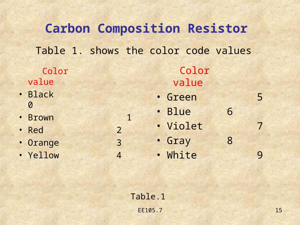
Color value
• Black 0• Brown 1• Red 2• Orange 3• Yellow 4
Color value• Green 5• Blue 6• Violet 7• Gray 8• White 9
Table.1
Table 1. shows the color code values
EE105.7 16
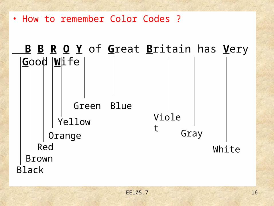
• How to remember Color Codes ?
B B R O Y of Great Britain has Very Good Wife
BlackBrown
RedOrange
Yellow
Green BlueViolet
Gray
White

EE105.7 17
Carbon Composition Resistor
Fig.3

EE105.7 18
Wire-wound Resistor
• Consists of a ceramic core wound with a drawn wire
• Have highest stability and highest power rating
• Is coated with an insulating material such as baked enamel

EE105.7 19
Different configurations of wire-wound resistors
1. Fixed resistor
2. Variable resistor Fixed Resistor:• Is one that has a single value of resistance which
remains constant• It has only two terminals
• Fig.4 shows a fixed resistor
Fig.4
EE105.7 20
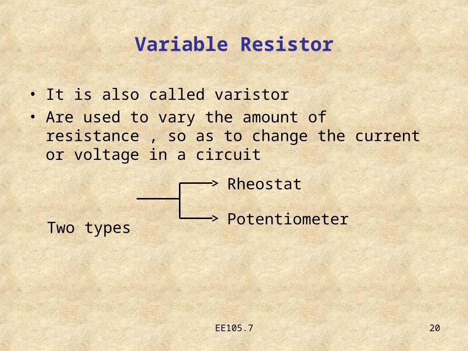
Variable Resistor
• It is also called varistor• Are used to vary the amount of resistance , so as to
change the current or voltage in a circuit
Two typesRheostat
Potentiometer

EE105.7 21
Rheostat
• It is a variable resistance with 2 terminals connected in series with a load along with a jockey which slides on the tube
• It is used to vary the amount of current• Fig.5 shows a simple rheostat

EE105.7 22
Rheostat
Fig.5
EE105.7 23
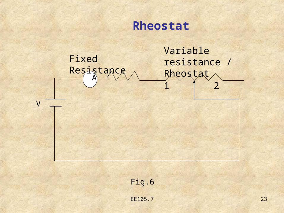
A
V
Fixed Resistance Variable resistance / Rheostat
1 2
Fig.6
Rheostat

EE105.7 24
• Fig.6 shows a simple rheostat connected in series with the source
• When sliding contact is in position 1, the current flowing through the circuit is maximum
• When sliding contact is in position 2, the current flowing through the circuit is minimum

EE105.7 25
Potentiometer
• It is a variable resistance with 3 terminals connected across voltage source along with sliding arm.
• It is used to vary the voltage division between the sliding arm and any one fixed end
• It is also called as pot• Fig.7 shows a simple potentiometer

EE105.7 26
Potentiometer
Fig.7

EE105.7 27
Potentiometer
Input Voltage
Output Voltage
3
2
1
Fig.8 shows potentiometer connected across voltage source to function as a voltage divider
(a) Wiring diagram (b) Schematic diagramFig.8
1
23
(b) Schematic diagram
1
23

EE105.7 28
Potentiometer
From the fig.8 • When the variable arm is at middle then the output
voltage is half of the input voltage between 1 & 2 terminals
• When the variable arm is closer to terminal 3(maximum R) more input voltage is available between 2 & 1 as output.
• When the variable arm is closer to terminal 1(minimum R) then the output voltage between 2 & 1 is minimum.

EE105.7 29
Comparison Between Rheostat & Potentiometer
Rheostat• Three terminals• In series with load &
voltage source• Varies the current
Potentiometer
• Three terminals• Ends are connected
across voltage source• Taps off part of voltage

EE105.7 30
Summary
In this lesson you learnt about
• Resistance
• Types of resistors
• Rheostat and Potentiometer
EE105.7 31
QUIZ

EE105.7 32
1. What is the color for 7 ?
a) White
b) Red
c) Violet
d) Yellow

EE105.7 33
2. Potentiometer has how many terminals ?
a) 1
b) 3
c) 2
d) none

EE105.7 34
1. List out the various types of resistors .
2. Define Resistance and give its units .
3. Compare Rheostat and Potentiometer .
Frequently Asked Questions

EE105.7 35
Thank You
Related Documents