0 EE-4232 Differential Amplifiers

Welcome message from author
This document is posted to help you gain knowledge. Please leave a comment to let me know what you think about it! Share it to your friends and learn new things together.
Transcript
0
EE-4232
Differential Amplifiers
1
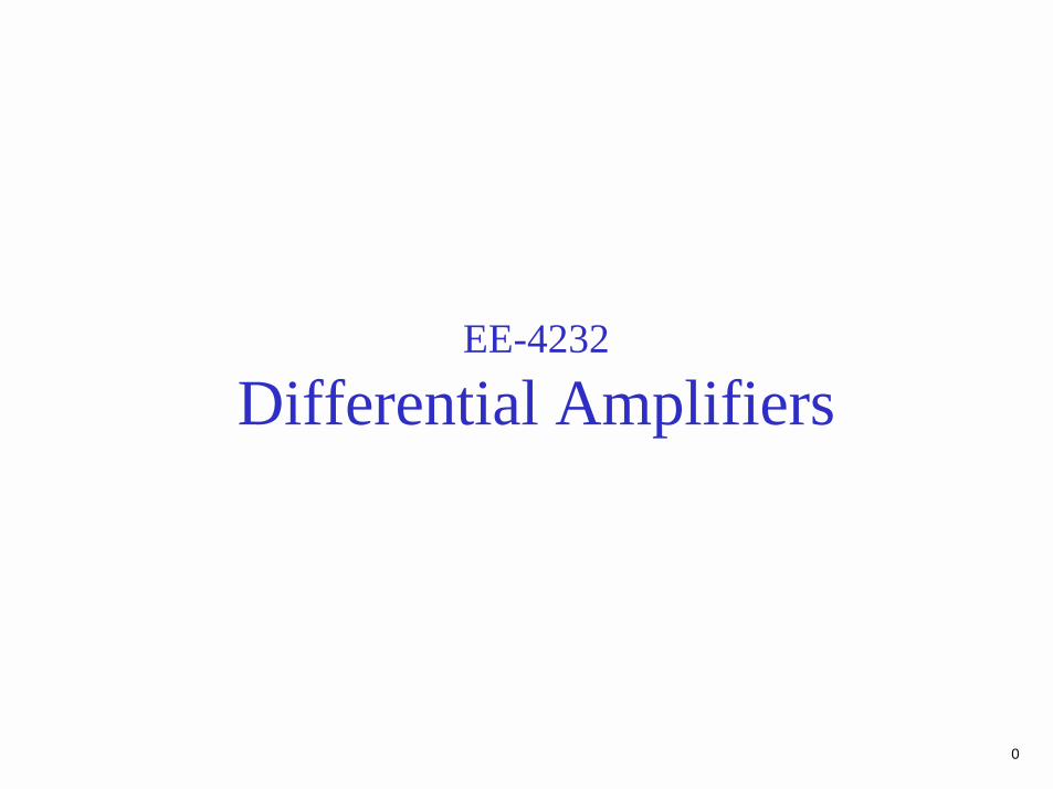
Different modes of operation of the differential pair: The differential pair with a common-mode input signal vCM.
2
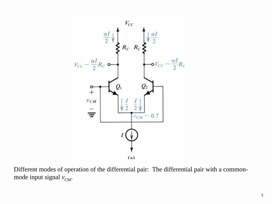
Different modes of operation of the differential pair: The differential pair with a “large”differential input signal.

3
Different modes of operation of the differential pair: The differential pair with a large input signal of polarity opposite to that in (b).
4
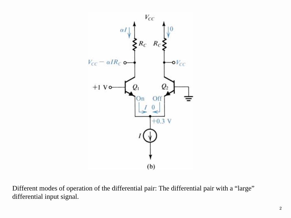
Different modes of operation of the differential pair: The differential pair with a small differential input signal vi.
5
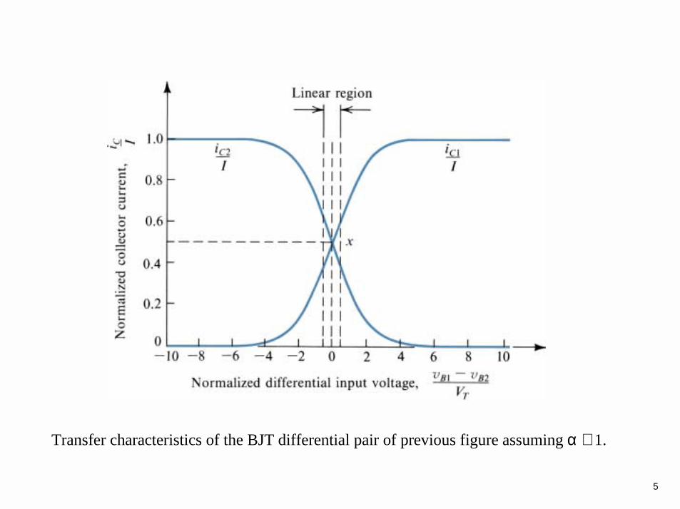
Transfer characteristics of the BJT differential pair of previous figure assuming α ≅ 1.
6
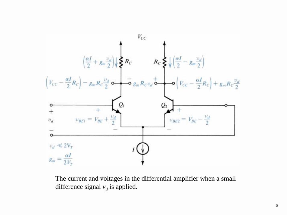
The current and voltages in the differential amplifier when a small difference signal vd is applied.

7
A simple technique for determining the signal currents in a differential amplifier excited by a differential voltage signal vd; dc quantities are not shown.
8
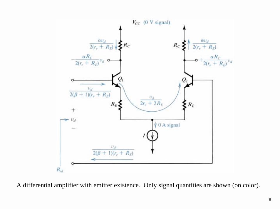
A differential amplifier with emitter existence. Only signal quantities are shown (on color).
9
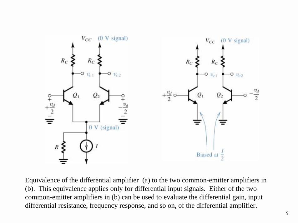
Equivalence of the differential amplifier (a) to the two common-emitter amplifiers in (b). This equivalence applies only for differential input signals. Either of the two common-emitter amplifiers in (b) can be used to evaluate the differential gain, input differential resistance, frequency response, and so on, of the differential amplifier.

10
(a) The differential amplifier fed by a common-mode voltage signal. (b) Equivalent “half-circuits” for the common-mode calculations.
11
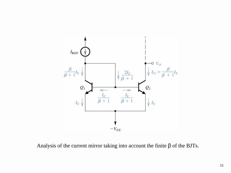
Analysis of the current mirror taking into account the finite β of the BJTs.
12
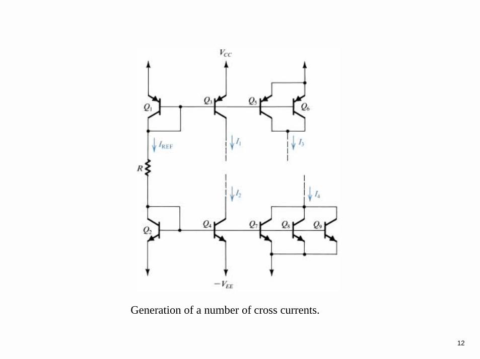
Generation of a number of cross currents.

13
A current mirror with base-current compensation.
14
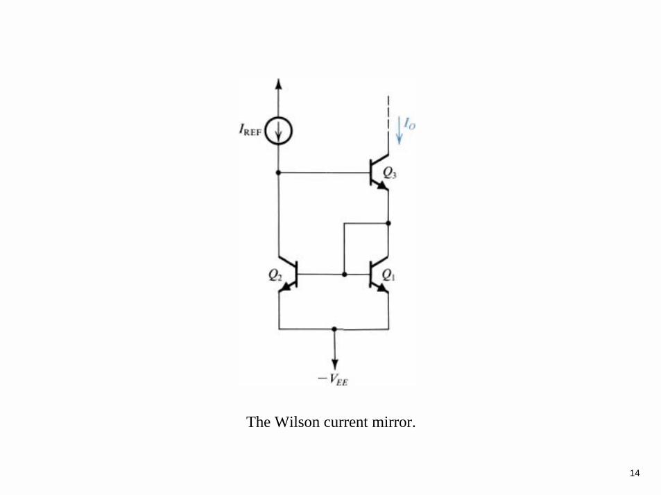
The Wilson current mirror.

15
The Widlar current source.
16
17
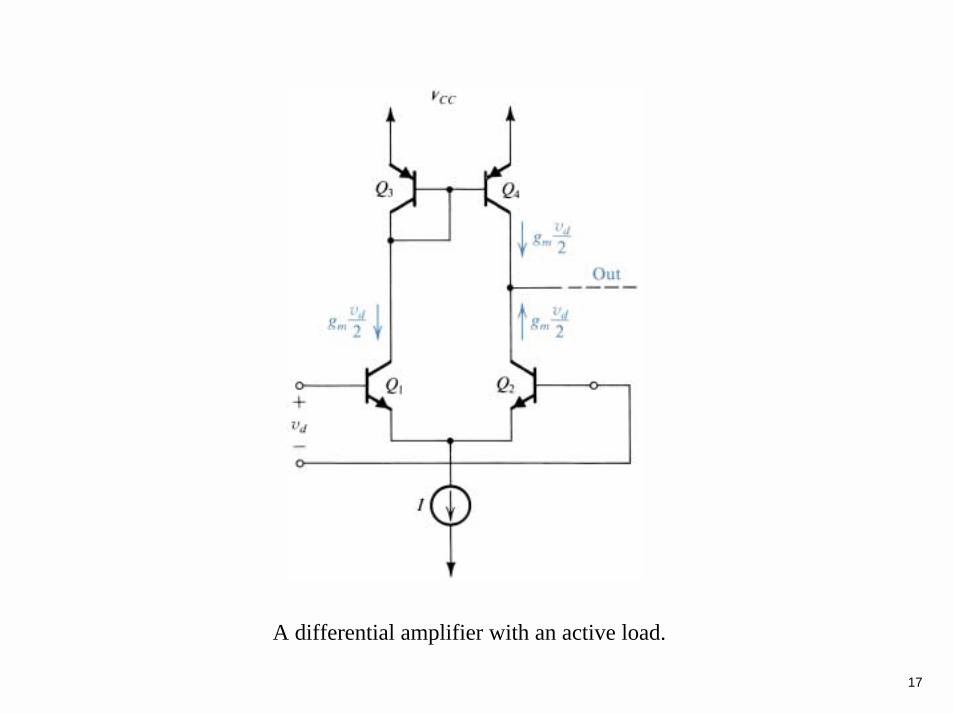
A differential amplifier with an active load.
18
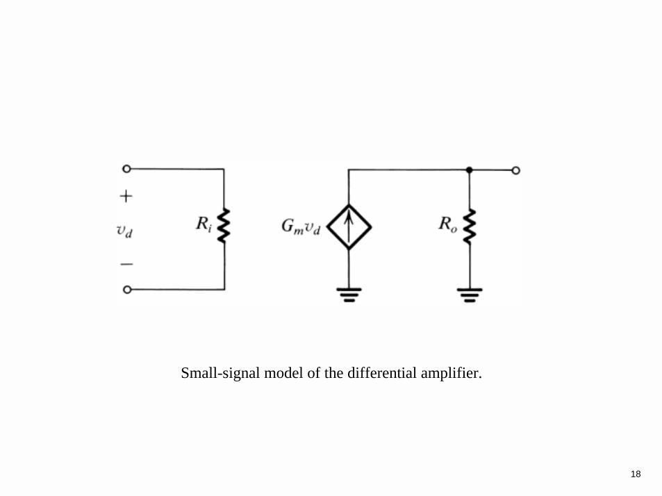
Small-signal model of the differential amplifier.
19
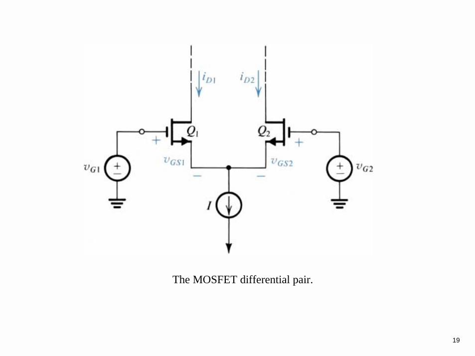
The MOSFET differential pair.
20
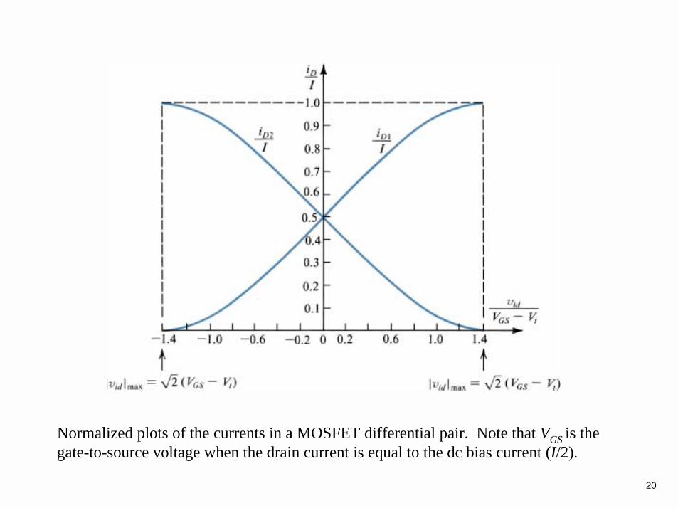
Normalized plots of the currents in a MOSFET differential pair. Note that VGS is the gate-to-source voltage when the drain current is equal to the dc bias current (I/2).
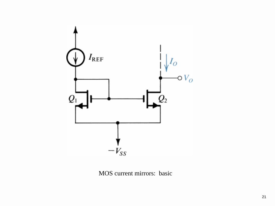
21
MOS current mirrors: basic

22
MOS current mirrors: cascode
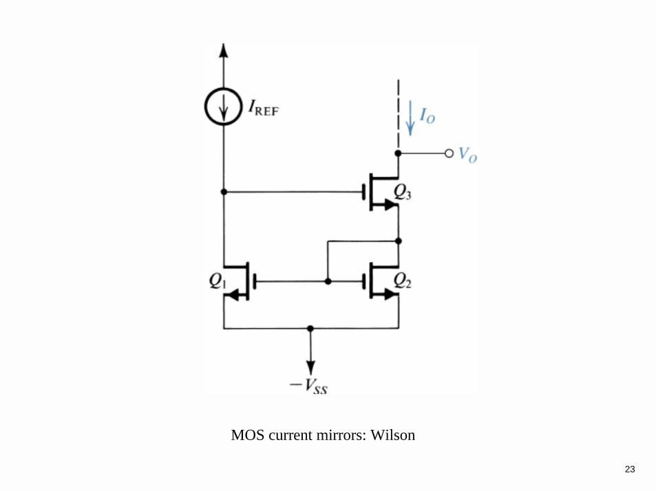
23
MOS current mirrors: Wilson
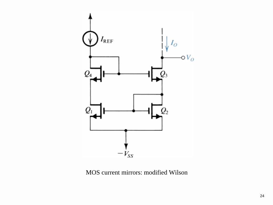
24
MOS current mirrors: modified Wilson

25
A multistage amplifier circuit.

26
References
• Electronics by A. Hambley• Microelectronics Circuits by Sedra & Smith• Other books on Electronics
Related Documents


