EE3170/CC/Lecture#12-Part II 1 EE 3170 Microcontroller Applications Lecture 13: Introduction to Microcontroller Hardware (Part II- Input/Output) - Miller §6.1 - §6.12 Based on slides for ECE3170 by Profs. Davis, Kieckhafer, Tan, and Cischke EE3170/CC/Lecture#13-Part II 2 Objectives Describe the I/O ports of the 6811 Explain the basic parts of I/O programming Give examples of I/O device drivers Understand simple I/O programs EE3170/CC/Lecture#13-Part II 3 Input/Output Architectures I/O Hardware Model 68HC11 I/O Organization Specific Port Examples PORTB PORTC Example of Polled I/O Operation Observations Interrupt-Driven I/O concept and requirements generic response to an interrupt request Interrupts in the 68HC11 hardware setup response to an interrupt request Example of Interrupt Driven I/O EE3170/CC/Lecture#13-Part II 4 How Does an Embedded System Interact with the World? An embedded system uses input/output devices to connect with the real world. Input devices get information from the external world, often through sensors. Output devices control physical systems or display information.

Welcome message from author
This document is posted to help you gain knowledge. Please leave a comment to let me know what you think about it! Share it to your friends and learn new things together.
Transcript
EE3170/CC/Lecture#12-Part II 111
EE 3170 Microcontroller Applications
Lecture 13: Introduction to Microcontroller Hardware (Part II- Input/Output)
- Miller §6.1 - §6.12
Based on slides for ECE3170 by Profs. Davis, Kieckhafer, Tan, and Cischke
EE3170/CC/Lecture#13-Part II 2
Objectives
Describe the I/O ports of the 6811
Explain the basic parts of I/O programming
Give examples of I/O device drivers
Understand simple I/O programs
EE3170/CC/Lecture#13-Part II 3
Input/Output ArchitecturesI/O Hardware Model
68HC11 I/O Organization
Specific Port ExamplesPORTBPORTC
Example of Polled I/O OperationObservations
Interrupt-Driven I/Oconcept and requirementsgeneric response to an interrupt request
Interrupts in the 68HC11hardware setupresponse to an interrupt request
Example of Interrupt Driven I/O
EE3170/CC/Lecture#13-Part II 4
How Does an Embedded System Interact with the World?
An embedded system uses input/output devices to connect with the real world.
Input devices get information from the external world, often through sensors.
Output devicescontrol physical systems ordisplay information.
EE3170/CC/Lecture#13-Part II 5
I/O Hardware ModelI/O ports are the parts of a microcomputer that connect to its environment.
A set of pins for data input or outputMaybe a register attached to the pinsThe control protocol for the pins
I/O Device =A device attached to the I/O port“Peripheral” to the computergenerates data and sends it to a port AND/ORreads data from the port, and acts on it
Device drivers are software routines that let higher level software use an I/O device.
You’re probably familiar with device drivers for your home computer.
EE3170/CC/Lecture#13-Part II 6
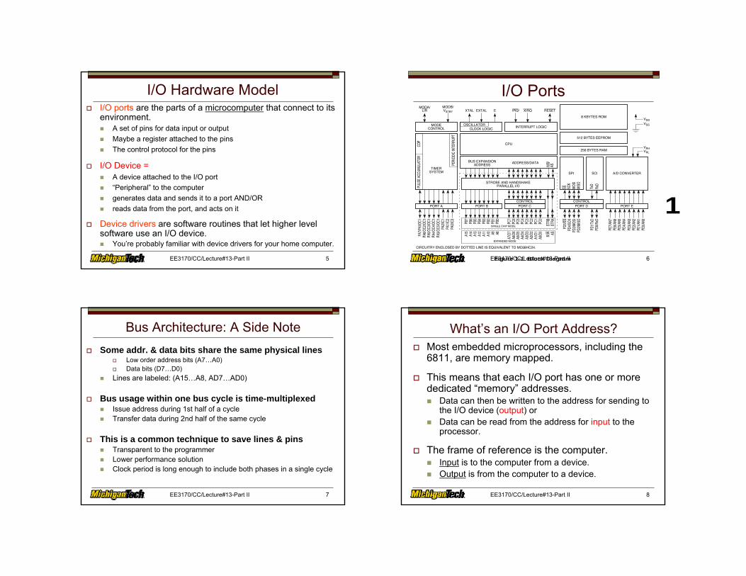
I/O Ports
M68HC11
GENERAL DESCRIPTION
MOTOROLA
REFERENCE MANUAL 1-3
1
Figure 1-1 Block Diagram
SPI A/D CONVERTERSCI
PORT DCONTROL
EXTALXTAL E
OSCILLATORCLOCK LOGIC INTERRUPT LOGIC
MODA/LIR
MODB/VSTBY
TIMERSYSTEM
CPUCOP
PULS
E AC
CUMU
LATO
R
STROBE AND HANDSHAKE
PORT B
PB7
PB6
PB5
PB4
PB3
PB2
PB1
PB0
PORT C
PC7
PC6
PC5
PC4
PC3
PC2
PC1
PC0
STRB
STRA
PD5/S
SPD
4/SCK
PD3/M
OSI
PD2/M
ISO
PD1/T
xDPD
0/RxD
PORT E
PE7/A
N7PE
6/AN6
PE5/A
N5PE
4/AN4
PE3/A
N3PE
2/AN2
PE1/A
N1PE
0/AN0
CONTROLPORT A
PA7/P
AI/O
C1PA
6/OC2
/OC1
PA5/O
C3/O
C1PA
4/OC4
/OC1
PA3/O
C5/O
C1PA
2/IC1
PA1/I
C2PA
0/IC3
BUS EXPANSION
PARALLEL I/O
ADDRESSADDRESS/DATA
R/W
AS
SS SCK
PERI
ODIC
INTE
RRUP
T
MODECONTROL
XIRQIRQ/ RESET
MOSI
MISO
256 BYTES RAM
512 BYTES EEPROM
8 KBYTES ROM
VRL
VRH
VSS
VDD
TxD
RxD
A15
A14
A13
A12
A11
A10 A9 A8
A7/D
7A6
/D6
A5/D
5A4
/D4
A3/D
3A2
/D2
A1/D
1A0
/D0
R/W AS
SINGLE CHIP MODE
EXPANDED MODE
CIRCUITRY ENCLOSED BY DOTTED LINE IS EQUIVALENT TO MC68HC24.
EE3170/CC/Lecture#13-Part II 7
Bus Architecture: A Side NoteSome addr. & data bits share the same physical lines
Low order address bits (A7…A0)Data bits (D7…D0)
Lines are labeled: (A15…A8, AD7…AD0)
Bus usage within one bus cycle is time-multiplexedIssue address during 1st half of a cycleTransfer data during 2nd half of the same cycle
This is a common technique to save lines & pinsTransparent to the programmerLower performance solutionClock period is long enough to include both phases in a single cycle
EE3170/CC/Lecture#13-Part II 8
What’s an I/O Port Address?Most embedded microprocessors, including the 6811, are memory mapped.
This means that each I/O port has one or more dedicated “memory” addresses.
Data can then be written to the address for sending to the I/O device (output) orData can be read from the address for input to the processor.
The frame of reference is the computer.Input is to the computer from a device.Output is from the computer to a device.
EE3170/CC/Lecture#13-Part II 9
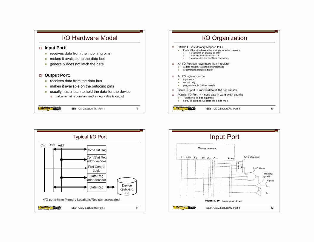
I/O Hardware ModelInput Port:
receives data from the incoming pinsmakes it available to the data busgenerally does not latch the data
Output Port:receives data from the data busmakes it available on the outgoing pinsusually has a latch to hold the data for the device
value remains constant until a new value is output
EE3170/CC/Lecture#13-Part II 10
I/O Organization68HC11 uses Memory Mapped I/O =
Each I/O port behaves like a single word of memoryIt recognizes an address as itselfIt transfers data on the data busIt responds to Load and Store commands
An I/O Port can have more than 1 registerA data register (latched or unlatched)A command/status register
An I/O register can beinput onlyoutput onlyprogrammable (bidirectional)
Serial I/O port ⇒ moves data at 1bit per transfer
Parallel I/O Port ⇒ moves data in word width chunksTypically 8-16 bits in parallel68HC11 parallel I/O ports are 8-bits wide
EE3170/CC/Lecture#13-Part II 11
Typical I/O Port Input Port
EE3170/CC/Lecture#13-Part II 12
Output Port
EE3170/CC/Lecture#13-Part II 13 EE3170/CC/Lecture#13-Part II 14
Command & Status RegisterThis C/S register is part of the I/O port
Usually one bit of it is a ready flag.
The c/s register has its own addressA different address than the data port
Purposes of C/S registerAllow processor to read status info on the port
e.g. Ready, Error, etc
Allow the processor to write commands to the portTo alter the way the port behaves
EE3170/CC/Lecture#13-Part II 15
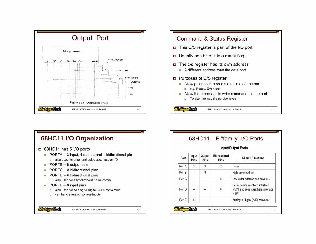
68HC11 I/O Organization68HC11 has 5 I/O ports
PORTA -- 3 input, 4 output, and 1 bidirectional pinalso used for timer and pulse accumulator I/O
PORTB -- 8 output pinsPORTC -- 8 bidirectional pinsPORTD -- 6 bidirectional pins
also used for asynchronous serial comm
PORTE -- 8 input pinsalso used for Analog to Digital (A/D) conversioncan handle analog voltage inputs
EE3170/CC/Lecture#13-Part II 16
68HC11 – E “family” I/O Ports
EE3170/CC/Lecture#13-Part II 17
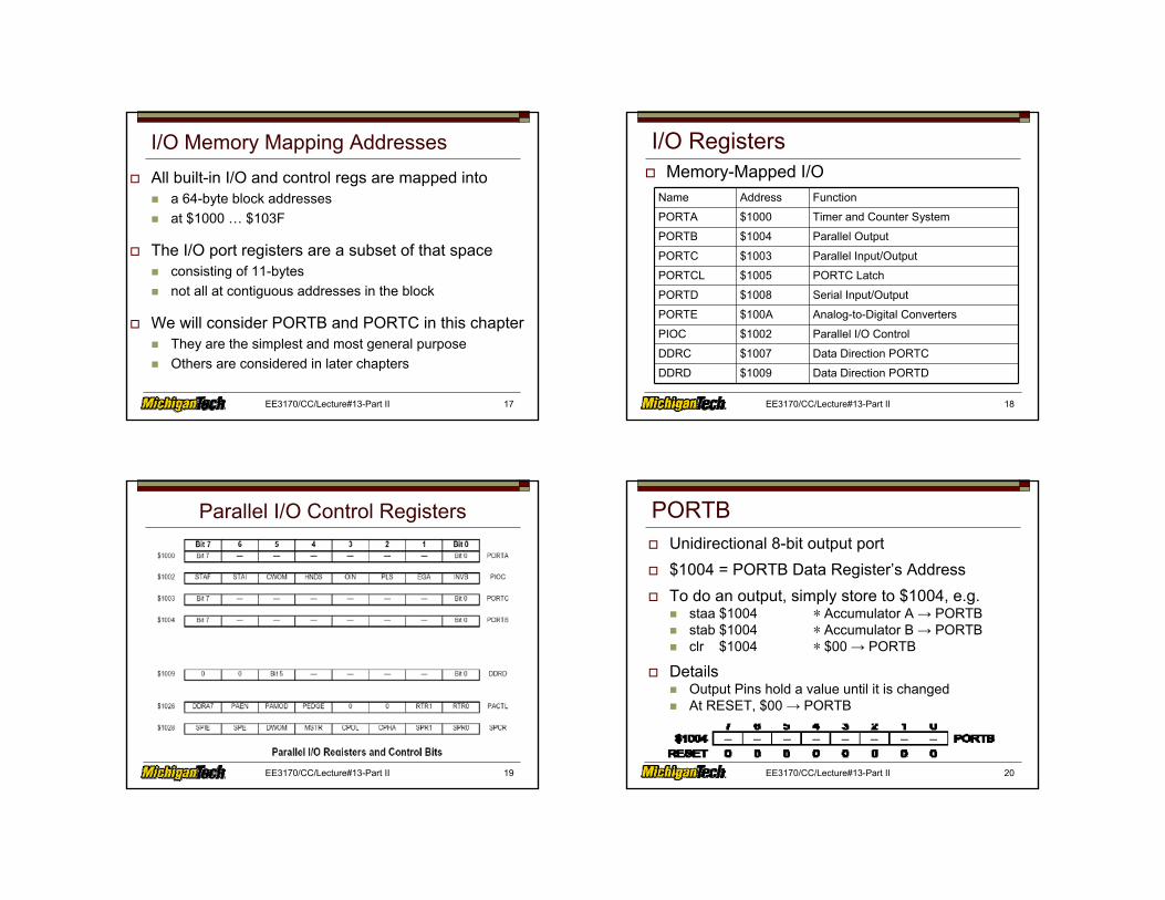
I/O Memory Mapping AddressesAll built-in I/O and control regs are mapped into
a 64-byte block addressesat $1000 … $103F
The I/O port registers are a subset of that spaceconsisting of 11-bytesnot all at contiguous addresses in the block
We will consider PORTB and PORTC in this chapterThey are the simplest and most general purposeOthers are considered in later chapters
EE3170/CC/Lecture#13-Part II 18
I/O Registers Memory-Mapped I/O
Name Address Function
PORTA $1000 Timer and Counter System
PORTB $1004 Parallel Output
PORTC $1003 Parallel Input/Output
PORTCL $1005 PORTC Latch
PORTD $1008 Serial Input/Output
PORTE $100A Analog-to-Digital Converters
PIOC $1002 Parallel I/O Control
DDRC $1007 Data Direction PORTC
DDRD $1009 Data Direction PORTD
EE3170/CC/Lecture#13-Part II 19
Parallel I/O Control Registers
EE3170/CC/Lecture#13-Part II 20
PORTBUnidirectional 8-bit output port$1004 = PORTB Data Register’s AddressTo do an output, simply store to $1004, e.g.
staa $1004 ∗ Accumulator A → PORTBstab $1004 ∗ Accumulator B → PORTBclr $1004 ∗ $00 → PORTB
DetailsOutput Pins hold a value until it is changedAt RESET, $00 → PORTB
EE3170/CC/Lecture#13-Part II 21
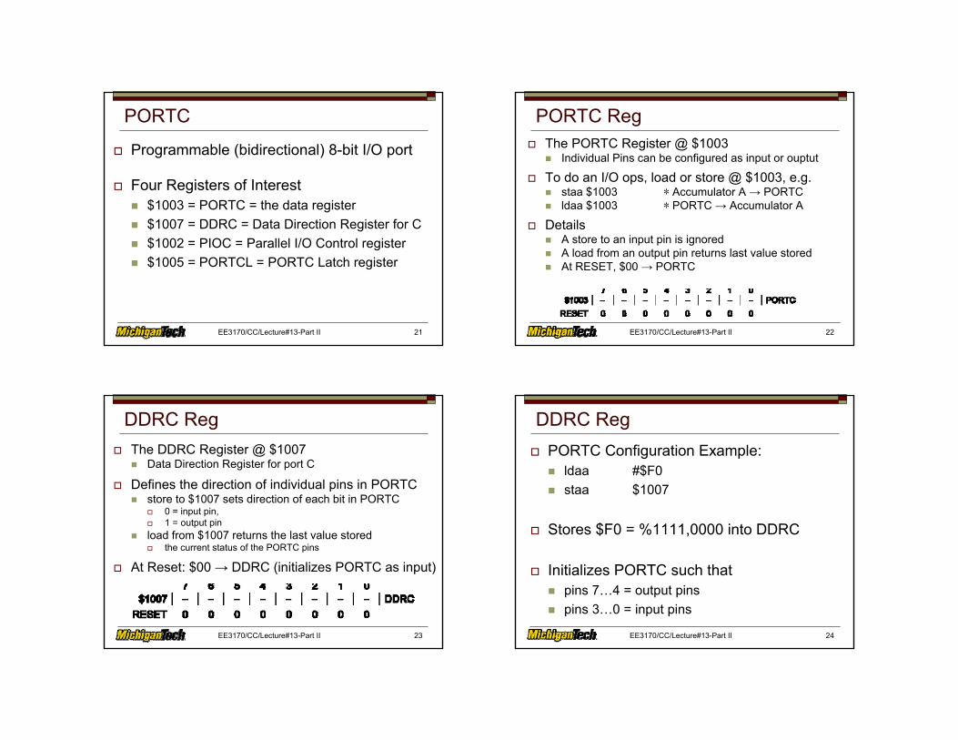
PORTC
Programmable (bidirectional) 8-bit I/O port
Four Registers of Interest$1003 = PORTC = the data register$1007 = DDRC = Data Direction Register for C$1002 = PIOC = Parallel I/O Control register$1005 = PORTCL = PORTC Latch register
EE3170/CC/Lecture#13-Part II 22
PORTC RegThe PORTC Register @ $1003
Individual Pins can be configured as input or ouptut
To do an I/O ops, load or store @ $1003, e.g.staa $1003 ∗ Accumulator A → PORTCldaa $1003 ∗ PORTC → Accumulator A
DetailsA store to an input pin is ignoredA load from an output pin returns last value storedAt RESET, $00 → PORTC
EE3170/CC/Lecture#13-Part II 23
DDRC RegThe DDRC Register @ $1007
Data Direction Register for port C
Defines the direction of individual pins in PORTCstore to $1007 sets direction of each bit in PORTC
0 = input pin,1 = output pin
load from $1007 returns the last value storedthe current status of the PORTC pins
At Reset: $00 → DDRC (initializes PORTC as input)
EE3170/CC/Lecture#13-Part II 24
DDRC RegPORTC Configuration Example:
ldaa #$F0staa $1007
Stores $F0 = %1111,0000 into DDRC
Initializes PORTC such thatpins 7…4 = output pinspins 3…0 = input pins
EE3170/CC/Lecture#13-Part II 25
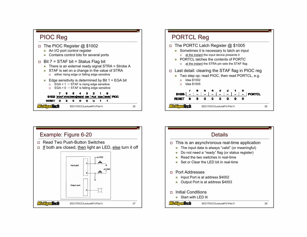
PIOC RegThe PIOC Register @ $1002
An I/O port control registerContains control bits for several ports
Bit 7 = STAF bit = Status Flag bitThere is an external ready signal STRA = Strobe ASTAF is set on a change in the value of STRA
either rising edge or falling edge sensitive
Edge sensitivity is determined by Bit 1 = EGA bitEGA = 1 ⇒ STAF is rising edge sensitiveEGA = 0 ⇒ STAF is falling edge sensitive
EE3170/CC/Lecture#13-Part II 26
PORTCL RegThe PORTC Latch Register @ $1005
Sometimes it is necessary to latch an inputat the instant the input device presents it
PORTCL latches the contents of PORTCat the instant the STRA pin sets the STAF flag
Last detail: clearing the STAF flag in PIOC regTwo step op: read PIOC, then read PORTCL, e.g.
ldaa $1002ldaa $1005
EE3170/CC/Lecture#13-Part II 27
Example: Figure 6-20Read Two Push-Button SwitchesIf both are closed, then light an LED, else turn it off
EE3170/CC/Lecture#13-Part II 28
DetailsThis is an asynchronous real-time application
The input data is always “valid” (or meaningful)Do not need a “ready” flag (or status register)Read the two switches in real-timeSet or Clear the LED bit in real-time
Port AddressesInput Port is at address $4002Output Port is at address $4003
Initial ConditionsStart with LED lit

EE3170/CC/Lecture#13-Part II 29
Flowchart for Program in Fig. 6-21
EE3170/CC/Lecture#13-Part II 30
Key Bit-Manipulation Instructions
bclr address, maskclear those bits of a mem word specified by the maski.e. M[offset] ← M[offset] AND (mask)Example:
M[offset] = 1101,0011mask = 0100,0001 (select bits 6 and 0)M[offset] ← (1101,0011) AND (1011,1110) = (1001,0110)
bset works the same to set the selected bits
EE3170/CC/Lecture#13-Part II 31
Bit Manipulation Instructions
EE3170/CC/Lecture#13-Part II 32
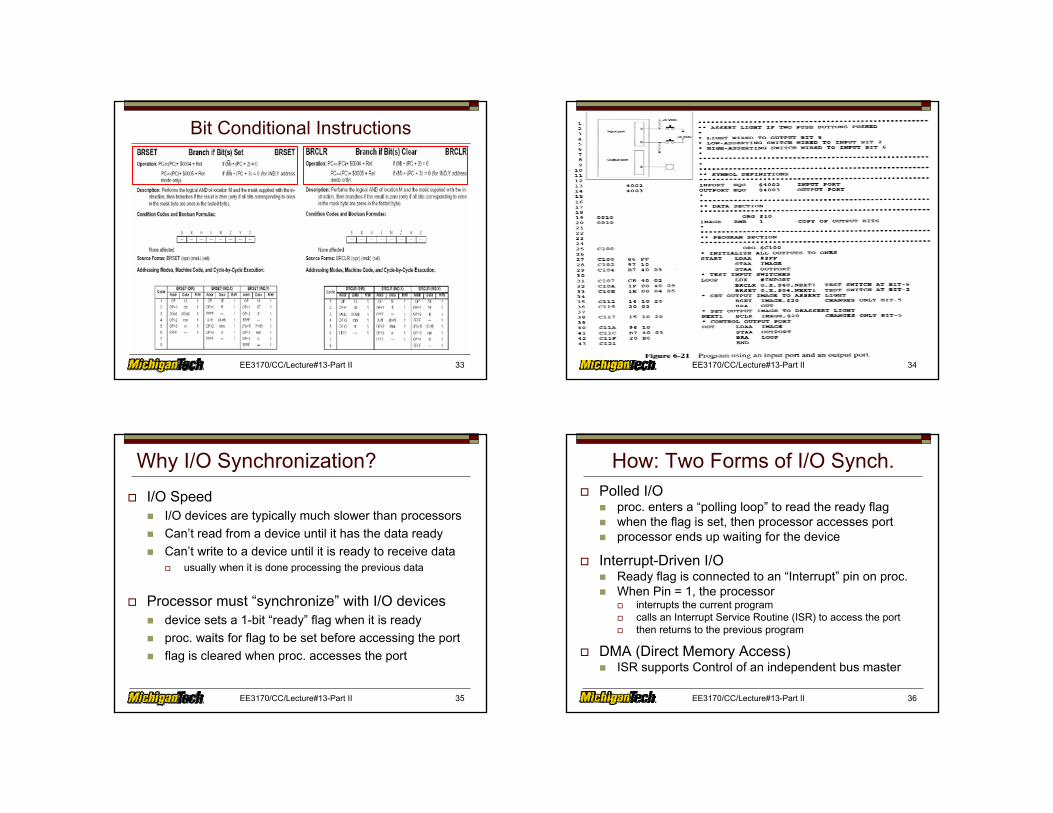
Key Bit-Conditional Instructionsbrclr offset, X, mask, target
examines a memory word, M[X+offset]If all bits selected by the mask byte are clear (= 0)Then branch to the target addressIn other words:
IF M[X=offset] AND mask = $00THEN Branch to Target
brset works the same if the selected bits are set to 1
EE3170/CC/Lecture#13-Part II 33
Bit Conditional Instructions
EE3170/CC/Lecture#13-Part II 34
EE3170/CC/Lecture#13-Part II 35
Why I/O Synchronization?I/O Speed
I/O devices are typically much slower than processorsCan’t read from a device until it has the data readyCan’t write to a device until it is ready to receive data
usually when it is done processing the previous data
Processor must “synchronize” with I/O devicesdevice sets a 1-bit “ready” flag when it is readyproc. waits for flag to be set before accessing the portflag is cleared when proc. accesses the port
EE3170/CC/Lecture#13-Part II 36
How: Two Forms of I/O Synch.Polled I/O
proc. enters a “polling loop” to read the ready flagwhen the flag is set, then processor accesses portprocessor ends up waiting for the device
Interrupt-Driven I/OReady flag is connected to an “Interrupt” pin on proc.When Pin = 1, the processor
interrupts the current programcalls an Interrupt Service Routine (ISR) to access the portthen returns to the previous program
DMA (Direct Memory Access)ISR supports Control of an independent bus master
EE3170/CC/Lecture#13-Part II 37
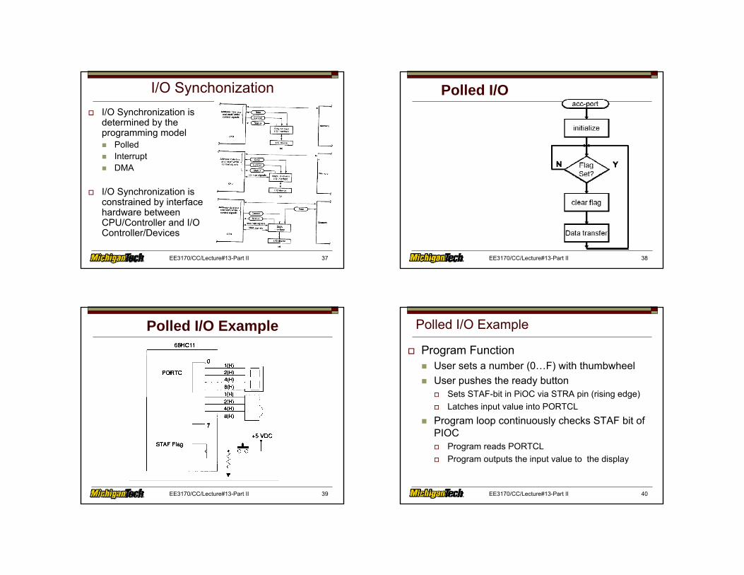
I/O SynchonizationI/O Synchronization isdetermined by theprogramming model
PolledInterruptDMA
I/O Synchronization isconstrained by interfacehardware betweenCPU/Controller and I/OController/Devices
EE3170/CC/Lecture#13-Part II 38
Polled I/O
EE3170/CC/Lecture#13-Part II 39
Polled I/O Example
EE3170/CC/Lecture#13-Part II 40
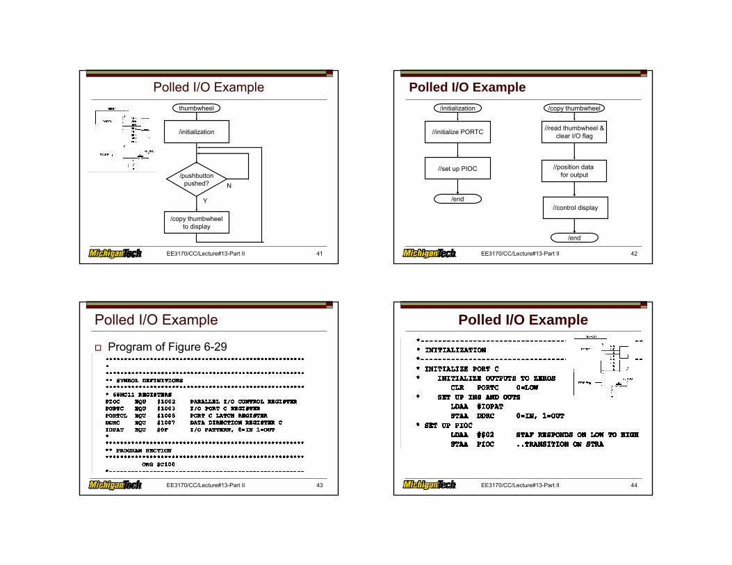
Polled I/O Example
Program FunctionUser sets a number (0…F) with thumbwheelUser pushes the ready button
Sets STAF-bit in PiOC via STRA pin (rising edge)Latches input value into PORTCL
Program loop continuously checks STAF bit of PIOC
Program reads PORTCLProgram outputs the input value to the display
EE3170/CC/Lecture#13-Part II 41
Polled I/O Examplethumbwheel
/initialization
/pushbuttonpushed?
/copy thumbwheelto display
Y
N
EE3170/CC/Lecture#13-Part II 42
Polled I/O Example/initialization
//initialize PORTC
//set up PIOC
/end
/copy thumbwheel
//read thumbwheel &clear I/O flag
//position data for output
/end
//control display
EE3170/CC/Lecture#13-Part II 43
Polled I/O Example
Program of Figure 6-29
EE3170/CC/Lecture#13-Part II 44
Polled I/O Example
EE3170/CC/Lecture#13-Part II 45
Polled I/O Example
EE3170/CC/Lecture#13-Part II 46
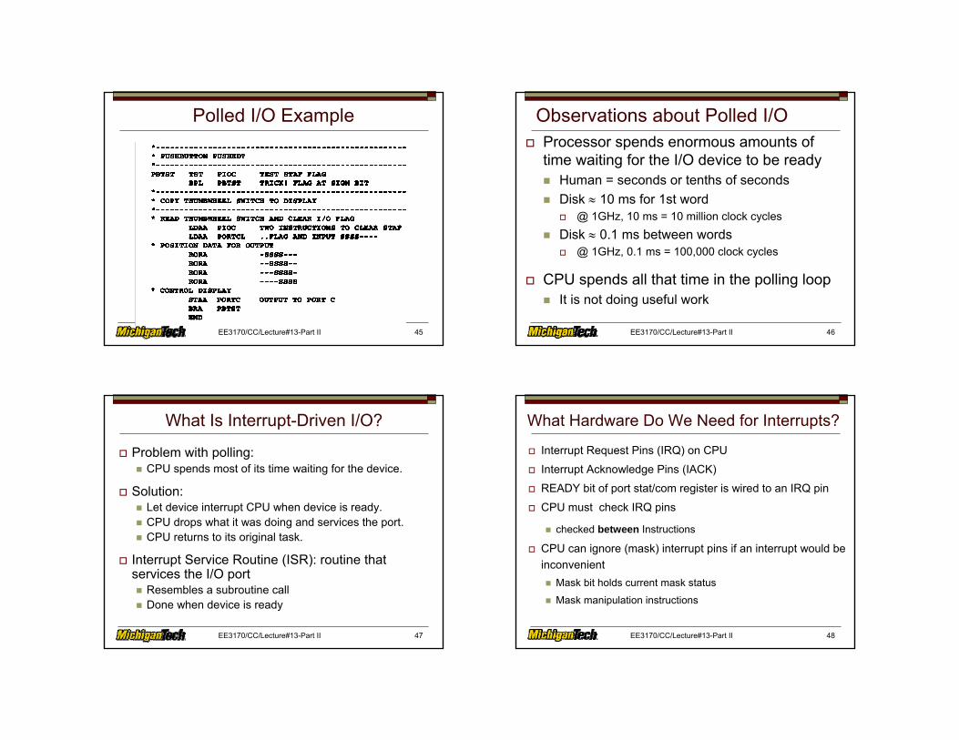
Observations about Polled I/OProcessor spends enormous amounts of time waiting for the I/O device to be ready
Human = seconds or tenths of secondsDisk ≈ 10 ms for 1st word
@ 1GHz, 10 ms = 10 million clock cyclesDisk ≈ 0.1 ms between words
@ 1GHz, 0.1 ms = 100,000 clock cycles
CPU spends all that time in the polling loopIt is not doing useful work
EE3170/CC/Lecture#13-Part II 47
What Is Interrupt-Driven I/O?
Problem with polling:CPU spends most of its time waiting for the device.
Solution:Let device interrupt CPU when device is ready. CPU drops what it was doing and services the port.CPU returns to its original task.
Interrupt Service Routine (ISR): routine that services the I/O port
Resembles a subroutine callDone when device is ready
EE3170/CC/Lecture#13-Part II 48
What Hardware Do We Need for Interrupts?
Interrupt Request Pins (IRQ) on CPU
Interrupt Acknowledge Pins (IACK)
READY bit of port stat/com register is wired to an IRQ pin
CPU must check IRQ pins
checked between Instructions
CPU can ignore (mask) interrupt pins if an interrupt would be inconvenient
Mask bit holds current mask status
Mask manipulation instructions
EE3170/CC/Lecture#13-Part II 49
How Does Hardware Respond to an IRQ?
IF IRQ is masked, THEN ignore interrupt
ELSEIdentify the originator of the interruptFind the address of the ISRPush the process state on the stack
Program Counter - address of next instruction to be fetchedProgram Status - e.g. Condition Code registerMost CPUs don’t save general purpose registers
Takes a lot of timeLet the ISR push any registers it needs
PC ← Address of ISR routine
EE3170/CC/Lecture#13-Part II 50
How is Return from Interrupt Handled?
Initiated by Return from Interrupt instruction at end of Interrupt Service Routine
68HC11 = RTI
Undo all stack ops done by the interrupt
The next instruction the CPU fetches will be the next instruction of the previous task.
EE3170/CC/Lecture#13-Part II 51
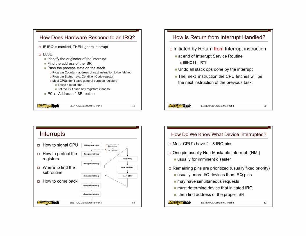
Interrupts
How to signal CPU
How to protect the registers
Where to find the subroutine
How to come back
STRB pulse high
doing something
doing something
doing something
doing something
doing something
read PIOC
read PORTCL
reset STAF
Convertingin
background
EE3170/CC/Lecture#13-Part II 52
How Do We Know What Device Interrupted?
Most CPU's have 2 - 8 IRQ pins
One pin usually Non-Maskable Interrupt (NMI)usually for imminent disaster
Remaining pins are prioritized (usually fixed priority)usually more I/O devices than IRQ pinsmay have simultaneous requestsmust determine device that initiated IRQthen find address of the proper ISR
EE3170/CC/Lecture#13-Part II 53
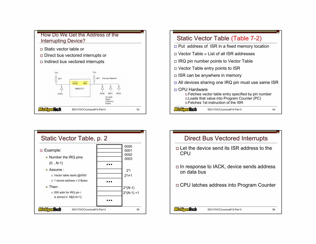
How Do We Get the Address of the Interrupting Device?
Static vector table orDirect bus vectored interrupts orIndirect bus vectored interrupts
EE3170/CC/Lecture#13-Part II 54
Static Vector Table (Table 7-2)Put address of ISR in a fixed memory location
Vector Table ≡ List of all ISR addresses
IRQ pin number points to Vector TableVector Table entry points to ISRISR can be anywhere in memoryAll devices sharing one IRQ pin must use same ISRCPU Hardware
Fetches vector table entry specified by pin numberLoads that value into Program Counter (PC)Fetches 1st instruction of the ISR
EE3170/CC/Lecture#13-Part II 55
Static Vector Table, p. 2
Example:
Number the IRQ pins (0…N-1)
Assume :Vector table starts @0000
1 stored address = 2 Bytes
Then:ISR addr for IRQ pin i is stored in M[2i:2i+1]
000000010002
2*(N-1)
0003
2*i2*i+1
...
...
...2*(N-1) +1
EE3170/CC/Lecture#13-Part II 56
Direct Bus Vectored InterruptsLet the device send its ISR address to the CPU
In response to IACK, device sends address on data bus
CPU latches address into Program Counter
EE3170/CC/Lecture#13-Part II 57
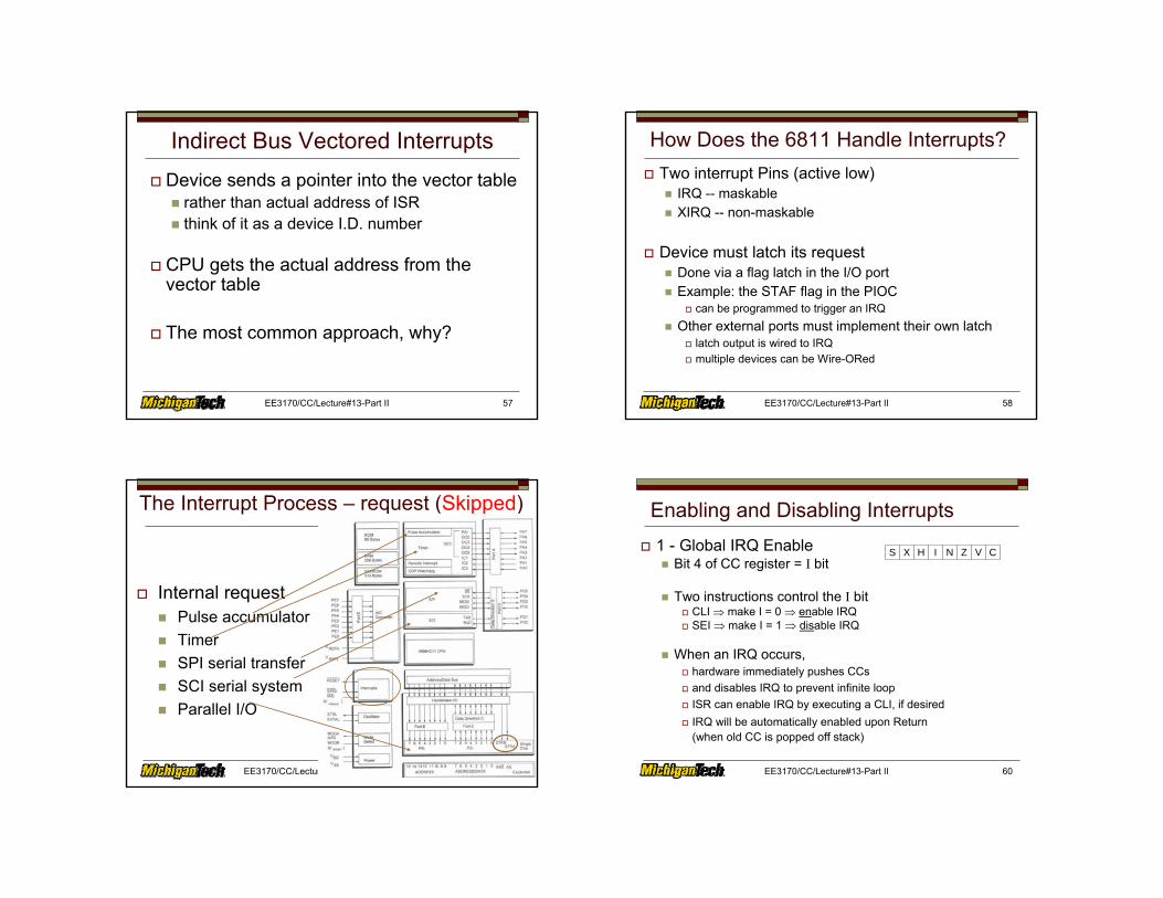
Indirect Bus Vectored InterruptsDevice sends a pointer into the vector table
rather than actual address of ISRthink of it as a device I.D. number
CPU gets the actual address from the vector table
The most common approach, why?
EE3170/CC/Lecture#13-Part II 58
How Does the 6811 Handle Interrupts?Two interrupt Pins (active low)
IRQ -- maskableXIRQ -- non-maskable
Device must latch its requestDone via a flag latch in the I/O portExample: the STAF flag in the PIOC
can be programmed to trigger an IRQOther external ports must implement their own latch
latch output is wired to IRQmultiple devices can be Wire-ORed
EE3170/CC/Lecture#13-Part II 59
The Interrupt Process – request (Skipped)
Internal requestPulse accumulator TimerSPI serial transferSCI serial systemParallel I/O
EE3170/CC/Lecture#13-Part II 60
Enabling and Disabling Interrupts1 - Global IRQ Enable
Bit 4 of CC register = I bit
Two instructions control the I bitCLI ⇒ make I = 0 ⇒ enable IRQSEI ⇒ make I = 1 ⇒ disable IRQ
When an IRQ occurs,hardware immediately pushes CCsand disables IRQ to prevent infinite loopISR can enable IRQ by executing a CLI, if desiredIRQ will be automatically enabled upon Return(when old CC is popped off stack)
S CVZNIHX
EE3170/CC/Lecture#13-Part II 61
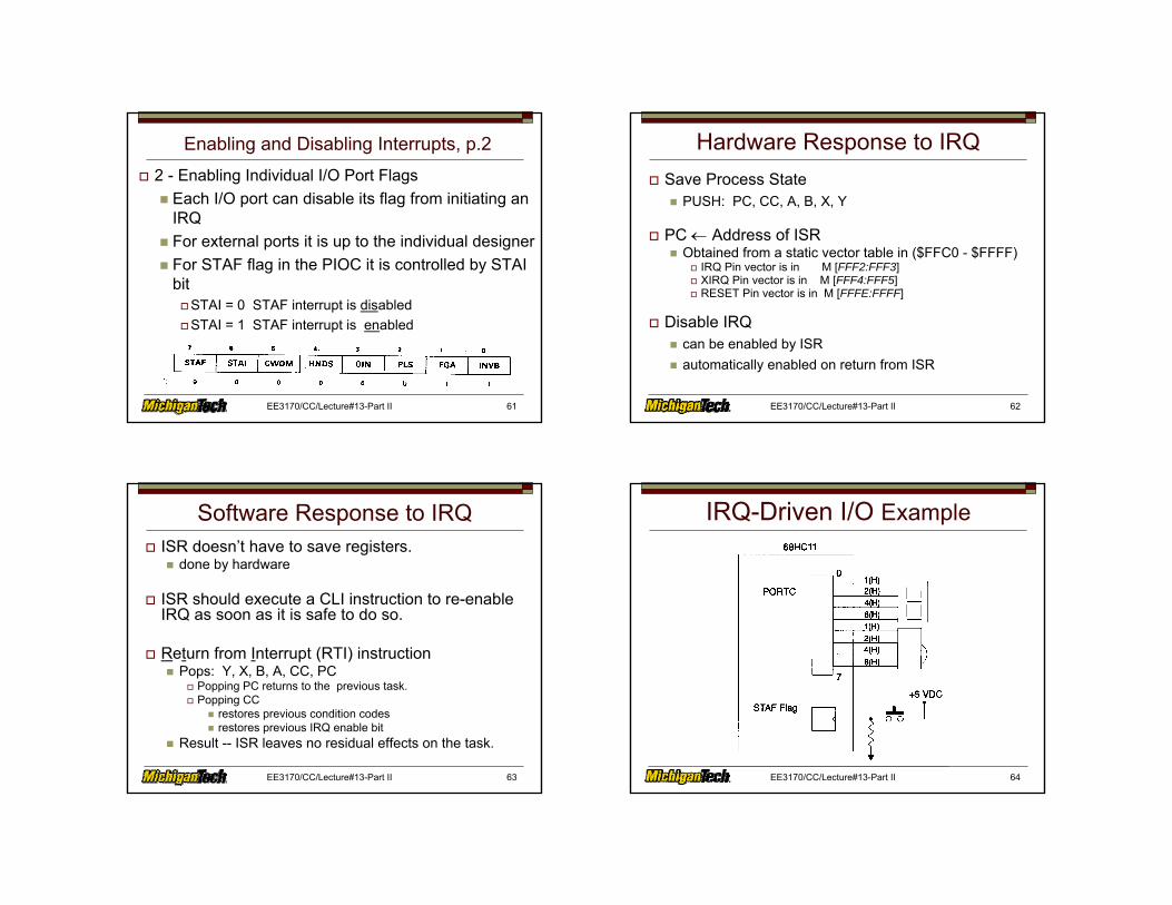
Enabling and Disabling Interrupts, p.22 - Enabling Individual I/O Port Flags
Each I/O port can disable its flag from initiating an IRQFor external ports it is up to the individual designerFor STAF flag in the PIOC it is controlled by STAI bit
STAI = 0 STAF interrupt is disabledSTAI = 1 STAF interrupt is enabled
EE3170/CC/Lecture#13-Part II 62
Hardware Response to IRQSave Process State
PUSH: PC, CC, A, B, X, Y
PC ← Address of ISRObtained from a static vector table in ($FFC0 - $FFFF)
IRQ Pin vector is in M [FFF2:FFF3]XIRQ Pin vector is in M [FFF4:FFF5]RESET Pin vector is in M [FFFE:FFFF]
Disable IRQcan be enabled by ISRautomatically enabled on return from ISR
EE3170/CC/Lecture#13-Part II 63
Software Response to IRQISR doesn’t have to save registers.
done by hardware
ISR should execute a CLI instruction to re-enable IRQ as soon as it is safe to do so.
Return from Interrupt (RTI) instructionPops: Y, X, B, A, CC, PC
Popping PC returns to the previous task.Popping CC
restores previous condition codesrestores previous IRQ enable bit
Result -- ISR leaves no residual effects on the task.
EE3170/CC/Lecture#13-Part II 64
IRQ-Driven I/O Example

EE3170/CC/Lecture#13-Part II 65
IRQ-Driven I/O ExampleSame Problem, Different Synchronization
User sets a number (0…F) with thumbwheelUser pushes the ready button (P.288)
sets STAF-bit in PIOC via STRA pin (rising edge)Latches input value into PORTCLSets IRQ input: ← STAF Output
Program is InterruptedISR reads PORTCLISR outputs the input value to the displayISR returns to main program
EE3170/CC/Lecture#13-Part II 66
IRQ-Driven I/O Example
thumbwheel
/initialization
/do something else(something useful)
IRQ ISR
/copy thumbwheel
/end
/return to mainprogram
/valid STAFinterr?
EE3170/CC/Lecture#13-Part II 67
IRQ-Driven I/O Example
/initialization
//initialize PORTC
//set up PIOC
/end
/copy thumbwheel
//read thumbwheel &clear I/O flag
//position data for output
/end
//control display
EE3170/CC/Lecture#13-Part II 68
IRQ-Driven I/O Example
EE3170/CC/Lecture#13-Part II 69
IRQ-Driven I/O Example
EE3170/CC/Lecture#13-Part II 70
IRQ-Driven I/O Example
EE3170/CC/Lecture#13-Part II 71
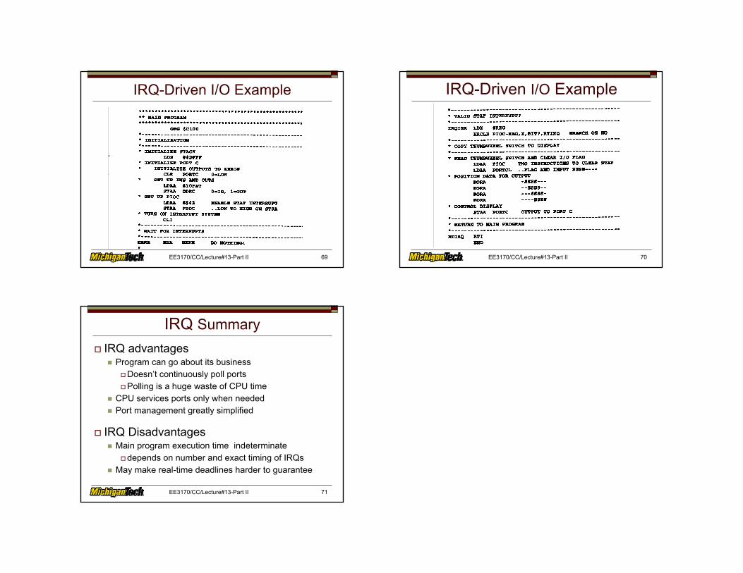
IRQ SummaryIRQ advantages
Program can go about its businessDoesn’t continuously poll portsPolling is a huge waste of CPU time
CPU services ports only when neededPort management greatly simplified
IRQ DisadvantagesMain program execution time indeterminate
depends on number and exact timing of IRQsMay make real-time deadlines harder to guarantee
Related Documents


