MBEC EE 2355 DESIGN OF ELECTRICAL MACHINES SYLLABUS EE2355 DESIGN OF ELECTRICAL MACHINES L T P C 3 1 0 4 UNIT I INTRODUCTION 9 Major considerations in Electrical Machine Design - Electrical Engineering Materials – Space factor – Choice of Specific Electrical and Magnetic loadings - Thermal Considerations - Heat flow – Temperature rise - Rating of machines – Standard Specifications. UNIT II DC MACHINES 9 Output Equations – Main Dimensions - Magnetic circuit calculations – Carter’s Coefficient - Net length of Iron –Real & Apparent flux densities – Selection of number of poles – Design of Armature – Design of commutator and brushes – performance prediction using design values. UNIT III TRANSFORMERS 9 Output Equations – Main Dimensions - KVA output for single and three phase transformers – Window space factor – Overall dimensions – Operating characteristics – Regulation – No load current – Temperature rise in Transformers – Design of Tank - Methods of cooling of Transformers. UNIT IV INDUCTION MOTORS 9 Output equation of Induction motor – Main dimensions – Length of air gap- Rules for selecting rotor slots of squirrel cage machines – Design of rotor bars & slots – Design of end rings – Design of wound rotor -– Magnetic leakage calculations – Leakage reactance of polyphase machines- Magnetizing current - Short circuit current – Circle diagram - Operating characteristics. UNIT V SYNCHRONOUS MACHINES 9 Output equations – choice of loadings – Design of salient pole machines – Short circuit ratio – shape of pole face – Armature design – Armature parameters – Estimation of air gap length – Design of rotor –Design of damper winding – Determination of full load field mmf – Design of field winding – Design of turbo alternators – Rotor design. L = 45 T = 15 TOTAL = 60 PERIODS TEXT BOOKS 1. Sawhney, A.K., 'A Course in Electrical Machine Design', Dhanpat Rai & Sons, New Delhi, 1984. 2. Sen, S.K., 'Principles of Electrical Machine Designs with Computer Programmes', Oxford and IBH Publishing Co. Pvt. Ltd., New Delhi, 1987. REFERENCES 1. A.Shanmugasundaram, G.Gangadharan, R.Palani 'Electrical Machine Design Data Book', New Age Intenational Pvt. Ltd., Reprint 2007. 2. ‘Electrical Machine Design', Balbir Singh, Brite Publications, Pune. VI SEM EEE Er.R.RAMANATHAN, AP/EEE

Welcome message from author
This document is posted to help you gain knowledge. Please leave a comment to let me know what you think about it! Share it to your friends and learn new things together.
Transcript
MBEC EE 2355 DESIGN OF ELECTRICAL MACHINES
SYLLABUS
EE2355 DESIGN OF ELECTRICAL MACHINES L T P C 3 1 0 4
UNIT I INTRODUCTION 9 Major considerations in Electrical Machine Design - Electrical Engineering Materials – Space factor – Choice of Specific Electrical and Magnetic loadings - Thermal
Considerations - Heat flow – Temperature rise - Rating of machines – Standard
Specifications.
UNIT II DC MACHINES 9 Output Equations – Main Dimensions - Magnetic circuit calculations – Carter’s Coefficient - Net length of Iron –Real & Apparent flux densities – Selection of number of
poles – Design of Armature – Design of commutator and brushes – performance
prediction using design values.
UNIT III TRANSFORMERS 9
Output Equations – Main Dimensions - KVA output for single and three phase transformers – Window space factor – Overall dimensions – Operating characteristics –
Regulation – No load current – Temperature rise in Transformers – Design of Tank -
Methods of cooling of Transformers.
UNIT IV INDUCTION MOTORS 9 Output equation of Induction motor – Main dimensions – Length of air gap- Rules for selecting rotor slots of squirrel cage machines – Design of rotor bars & slots – Design of end rings – Design of wound rotor -– Magnetic leakage calculations – Leakage reactance of polyphase machines- Magnetizing current - Short circuit current – Circle diagram - Operating characteristics.
UNIT V SYNCHRONOUS MACHINES 9 Output equations – choice of loadings – Design of salient pole machines – Short circuit ratio – shape of pole face – Armature design – Armature parameters – Estimation of air gap length – Design of rotor –Design of damper winding – Determination of full load field mmf – Design of field winding – Design of turbo alternators – Rotor design.
L = 45 T = 15 TOTAL = 60 PERIODS
TEXT BOOKS 1. Sawhney, A.K., 'A Course in Electrical Machine Design', Dhanpat Rai & Sons,
New Delhi, 1984. 2. Sen, S.K., 'Principles of Electrical Machine Designs with Computer
Programmes', Oxford and IBH Publishing Co. Pvt. Ltd., New Delhi, 1987.
REFERENCES 1. A.Shanmugasundaram, G.Gangadharan, R.Palani 'Electrical Machine Design
Data Book', New Age Intenational Pvt. Ltd., Reprint 2007. 2. ‘Electrical Machine Design', Balbir Singh, Brite Publications, Pune.
VI SEM EEE Er.R.RAMANATHAN, AP/EEE
MBEC EE 2355 DESIGN OF ELECTRICAL MACHINES
UNIT-1 INTRODUCTION
PART-A
1. What are the major considerations to evolve a good design of electric machine?
The major considerations to evolve a good design are
i. Cost
ii. Durability
iii. Compliance with performance criteria as laid down in specifications. 2. What are the different types of electrical engineering materials?
1. Electrical conducting materials.
a. High conductivity materials
i. copper
ii aluminium
iii. Iron and steel
iv. Alloys of copper b.
Materials of high resistivity
i. materials used for precision work
ii. materials used for rheostats
iii. materials used for heating devices
2. Electrical carbon materials
3. Super conductivity
4. Magnetic material i. soft ii. hard magnetic material
5. Insulating material
3. Define space factor of a coil.
In an electro magnetic coil the ratio of the volume occupied by the wire in the winding or
the iron in the core to the total volume of the winding or the core.
VI SEM EEE Er.R.RAMANATHAN, AP/EEE
MBEC EE 2355 DESIGN OF ELECTRICAL MACHINES 4.Write down the classification of the magnetic material.
i. Ferro magnetic materials. ii. Para magnetic materials. iii. Dia magnetic materials. 5. What is specific magnetic and electric loading?
Specific Magnetic loading Specific Electric loading 6. What are the factors that decide the choice of specific magnetic & electric loading?
The value of magnetic loading is determined by
i. Maximum flux density in iron parts. ii. Magnetising current iii. Core losses
The value of electric loading is determined by
i. Permissible temperature rise. ii. Voltage rating of machine. iii. Size of machine. iv. Current density.
7. State the properties which determine the suitability of a material for insulating material.
There are many properties which determine the suitability of a material for use as an
insulating material.
i. resistivity or specific resistance ii. electric strength or breakdown voltage iii. permittivity iv. dielectric hysteresis
8. What is thermal consideration and heat flow?
The thermal circuit is concerned with mode and media for dissipation of heat produced
inside the machine on account of losses.
The heated parts of an electrical machine dissipate heat in to their surroundings by conduction, confection and radiation from the outer surface. VI SEM EEE Er.R.RAMANATHAN, AP/EEE
MBEC EE 2355 DESIGN OF ELECTRICAL MACHINES 9. What is temperature rise and rating of machines?
Temperature rise
The operating life of a machine depends upon the type of insulating materials
used in its contruction and the life of the insulating in turns materials depends upon the
temperature rise of the machine.
Rating of machine
The rating of an electrical machine is the power output or the designated
operating power limit based upon the certain definite conditions assigned to it by the
manufacturer. 10. Write a short note on standard specifications.
The standard specifications are the specifications issued by the standards organization of
a country. The standard specifications serve as guideline for the manufacturers to produce quality
products at economical prices.
The standard specifications for electrical machines include ratings, types of enclosure,
dimensions of conductors, name plate details, performance indicies, permissible temperature rise,
permissible loss, efficiency, etc…..
PART B
1. What are the main groups of electrical conducting materials? Describe the properties and applications of those materials.
Electrical conducting materials.
i. High conductivity materials ii. Materials of high resistivity
Properties
The fundamental requirements
i. Highest possible conductivity ii. Least possible temperature co-efficient of resistance iii. Adequate mechanical strength iv. Rollability and drawability v. Good weldability and solderability vi. Adequate resistance to corrosion
a . copper b. alluminium c. Iron and steel d.alloys of copper VI SEM EEE Er.R.RAMANATHAN, AP/EEE

MBEC EE 2355 DESIGN OF ELECTRICAL MACHINES
Applications
i. High conductivity materials
Making all types of winding required in electrical machine, apparatus and devices.
ii. High resistivity materials.
Making resistance and heating device.
2. Discuss about various duties and ratings of Rotating Machines and give their respective temperature — time curves.
Types of duties and ratings
i. continuous duty ii. short time duty iii. intermittent periodic duty iv. intermittent periodic duty with starting v. intermittent periodic duty with starting and braking vi. continuous duty with intermittent periodic loading vii. continuous duty with starting and braking
viii. continuous duty with periodic speed changes
\ draw temperature- time curves
3. Explain the methods used for determination of motor rating for variable load drives
with suitable diagram.
The four commonly used methods are
i. Method of average losses ii. Equivalent current method iii. Equivalent torque method iv. Eqivalent power method
Diagram and equation VI SEM EEE Er.R.RAMANATHAN, AP/EEE
MBEC EE 2355 DESIGN OF ELECTRICAL MACHINES
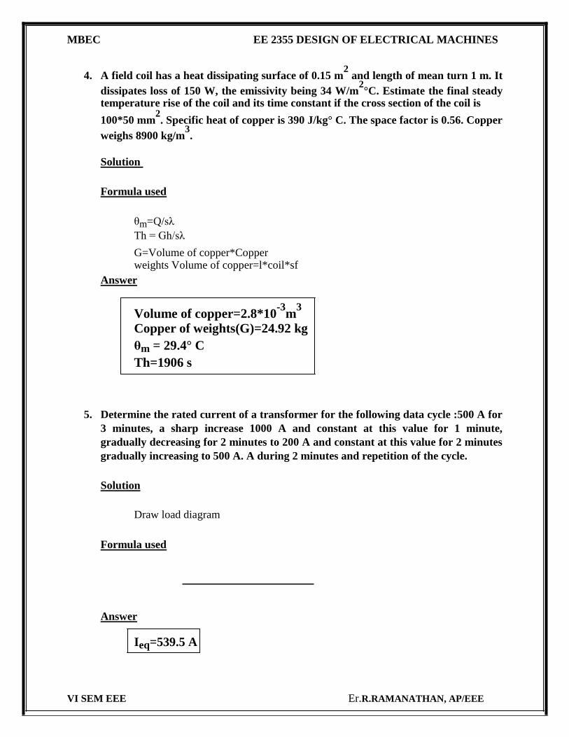
4. A field coil has a heat dissipating surface of 0.15 m2 and length of mean turn 1 m. It
dissipates loss of 150 W, the emissivity being 34 W/m2°C. Estimate the final steady
temperature rise of the coil and its time constant if the cross section of the coil is
100*50 mm2. Specific heat of copper is 390 J/kg° C. The space factor is 0.56. Copper
weighs 8900 kg/m3.
Solution
Formula used
θm=Q/sλ
Th = Gh/sλ
G=Volume of copper*Copper weights Volume of copper=l*coil*sf
Answer
Volume of copper=2.8*10-3
m3
Copper of weights(G)=24.92 kg
θm = 29.4° C Th=1906 s
5. Determine the rated current of a transformer for the following data cycle :500 A for
3 minutes, a sharp increase 1000 A and constant at this value for 1 minute,
gradually decreasing for 2 minutes to 200 A and constant at this value for 2 minutes
gradually increasing to 500 A. A during 2 minutes and repetition of the cycle.
Solution
Draw load diagram
Formula used
Answer
Ieq=539.5 A
VI SEM EEE Er.R.RAMANATHAN, AP/EEE
MBEC EE 2355 DESIGN OF ELECTRICAL MACHINES 6. Explain about standard specification also give Indian standard specification
for different electric machine.
IS 325-1966 : Specifications for 3ph induction motor
IS 4029-1967 : Guide for testing 3ph induction motor
IS12615-1986 : Specifications for energy efficient induction motor
IS13555-1993 : Guide for selection & application of 3ph induction motor for different types of driven equipment
IS8789-1996 : Values of performance characteristics for 3ph induction
motor IS 12066-1986: 3ph induction motors for machine tools
VI SEM EEE Er.R.RAMANATHAN, AP/EEE
MBEC EE 2355 DESIGN OF ELECTRICAL MACHINES
UNIT-II DC MACHINE
PART-A
1. What is meant by apparent and real flux density?
Apparent flux density Bapp =
Real flux density Breal =
2. Define field form factor
Field form factor ‘kf’ is defined as
kf =
=
3. What is carter’s gap co-efficient?
The Carter’s gap co-efficient (kcs) is the ratio of slot width to gap length.
The formula which gives the value of kcs directly is
Where lg = gap length
Ws = width of slot
4. Mention any two guiding factors for the choice of number of poles.
The frequency of the flux reversal in the armature core generally lies between 25 to 50HZ.
The value of current per parallel path is limited to about 200 A. Thus the
current/brush arm should not be more than 400 A.
5. Name any two methods to reduce the armature reaction?
*Compensating windings are provided to neutralize the effect of armature reaction. *By increasing the length of air gap at pole tips.
VI SEM EEE Er.R.RAMANATHAN, AP/EEE
MBEC EE 2355 DESIGN OF ELECTRICAL MACHINES
6. What is slot loading?
The slot loading is the number of ampere conductors per slot. This value
should not exceeds 1500 A. Iz.z ≤ 1500 A [Is = No of conductors/slot]
7. What are the effect of armature reaction?
i. Reduction in emf ii. Increase in iron loss iii. Sparking & ring fire iv. Delayed commutation
8. Show how specific magnetic & electric loading interdependent.
The output of a dc machine is proportional to the product of their specific loadings.
Paα (Bav*ac)
For a particular output values of specific & magnetic loadings are interdependent. (i.e) If one is chosen higher the valve of either has belower.
9. Derive the output equation of the dc machine.
Pa = (π DL Bav)(π Dac)n*10-3
=(
π2 Bav ac 10
-3)D
2 Ln
Where
C0 = π2 Bav ac 10
-3
10. What are the guiding factor for the choice of number of armature slots.
i. Slot pith ii. Slot loading iii. Flux pulsation iv. Commutation
VI SEM EEE Er.R.RAMANATHAN, AP/EEE
MBEC EE 2355 DESIGN OF ELECTRICAL MACHINES
PART B
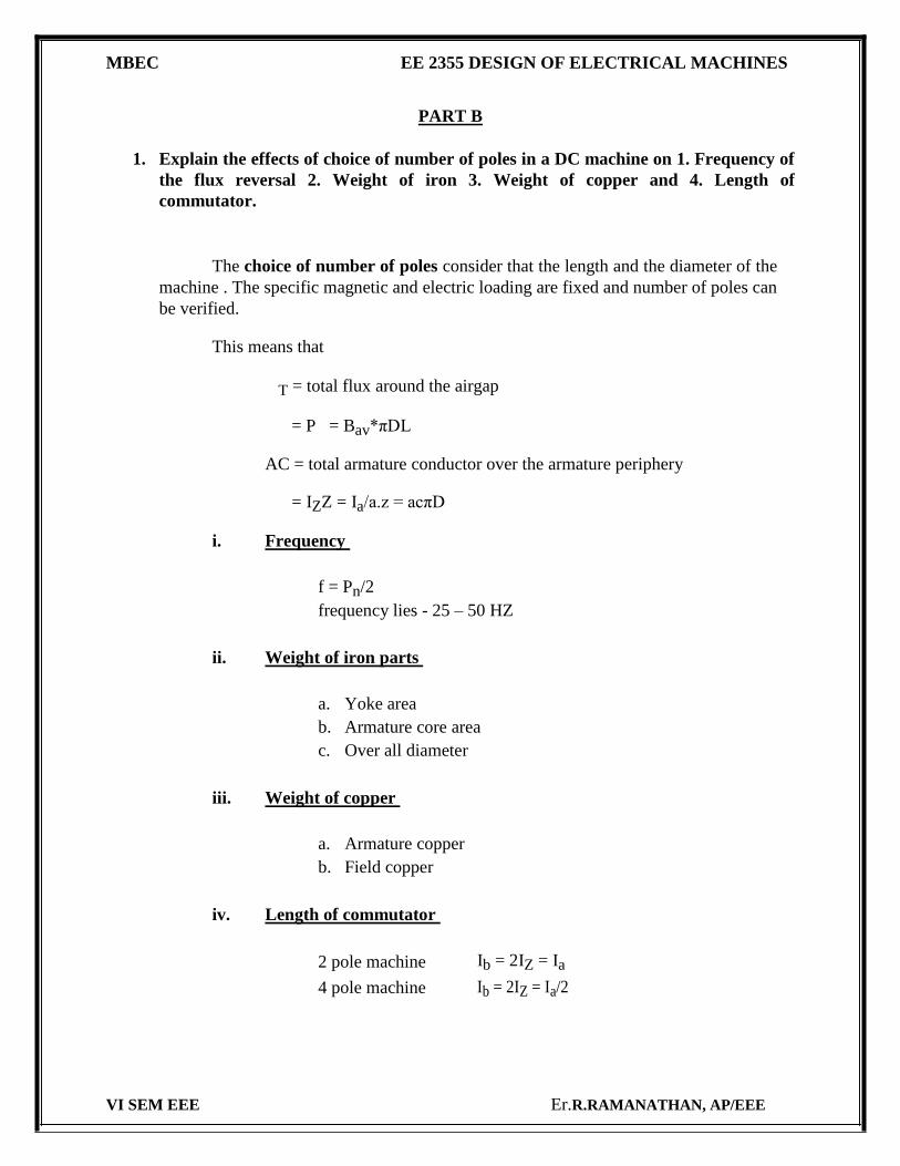
1. Explain the effects of choice of number of poles in a DC machine on 1. Frequency of
the flux reversal 2. Weight of iron 3. Weight of copper and 4. Length of
commutator.
The choice of number of poles consider that the length and the diameter of the
machine . The specific magnetic and electric loading are fixed and number of poles can
be verified.
This means that
T = total flux around the airgap
= P = Bav*πDL
AC = total armature conductor over the armature periphery
= IZZ = Ia/a.z = acπD
i. Frequency
f = Pn/2 frequency lies - 25 – 50 HZ
ii. Weight of iron parts
a. Yoke area b. Armature core area c. Over all diameter
iii. Weight of copper
a. Armature copper b. Field copper
iv. Length of commutator
2 pole machine Ib = 2IZ = Ia
4 pole machine Ib = 2IZ = Ia/2
VI SEM EEE Er.R.RAMANATHAN, AP/EEE
MBEC EE 2355 DESIGN OF ELECTRICAL MACHINES
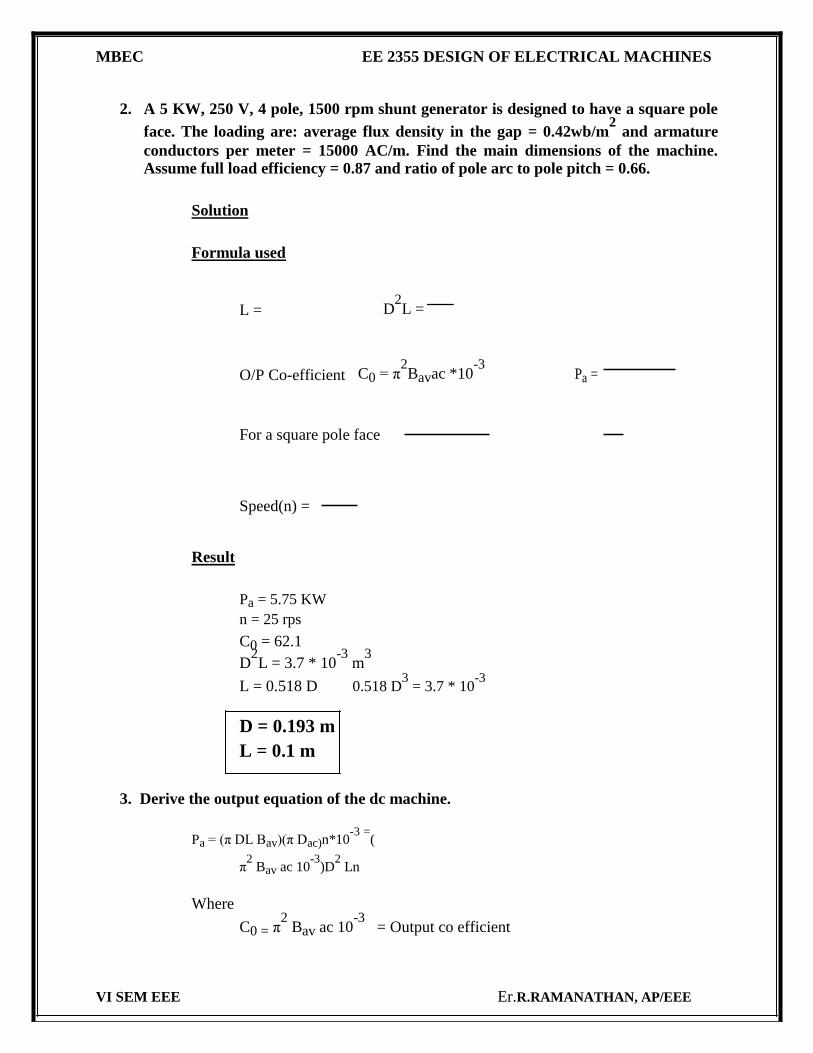
2. A 5 KW, 250 V, 4 pole, 1500 rpm shunt generator is designed to have a square pole
face. The loading are: average flux density in the gap = 0.42wb/m2 and armature
conductors per meter = 15000 AC/m. Find the main dimensions of the machine.
Assume full load efficiency = 0.87 and ratio of pole arc to pole pitch = 0.66.
Solution
Formula used
L = D2L =
O/P Co-efficient C0 = π2Bavac *10
-3 Pa =
For a square pole face
Speed(n) =
Result
Pa = 5.75 KW
n = 25 rps
C0 = 62.1
D2L = 3.7 * 10
-3 m
3
L = 0.518 D 0.518 D3 = 3.7 * 10
-3
D = 0.193 m L = 0.1 m
3. Derive the output equation of the dc machine.
Pa = (π DL Bav)(π Dac)n*10-3
=(
π2 Bav ac 10
-3)D
2 Ln
Where
C0 = π2 Bav ac 10
-3 = Output co efficient
VI SEM EEE Er.R.RAMANATHAN, AP/EEE
MBEC EE 2355 DESIGN OF ELECTRICAL MACHINES
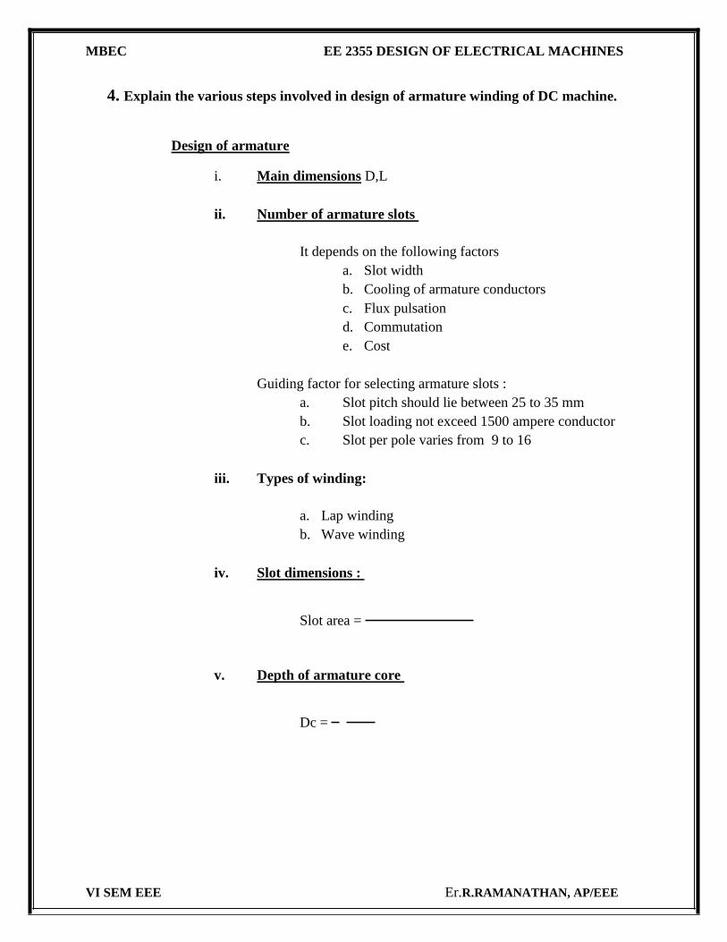
4. Explain the various steps involved in design of armature winding of DC machine.
Design of armature
i. Main dimensions D,L
ii. Number of armature slots
It depends on the following factors a. Slot width b. Cooling of armature conductors c. Flux pulsation d. Commutation e. Cost
Guiding factor for selecting armature slots : a. Slot pitch should lie between 25 to 35 mm b. Slot loading not exceed 1500 ampere conductor c. Slot per pole varies from 9 to 16
iii. Types of winding:
a. Lap winding b. Wave winding
iv. Slot dimensions :
Slot area =
v. Depth of armature core
Dc =
VI SEM EEE Er.R.RAMANATHAN, AP/EEE
MBEC EE 2355 DESIGN OF ELECTRICAL MACHINES
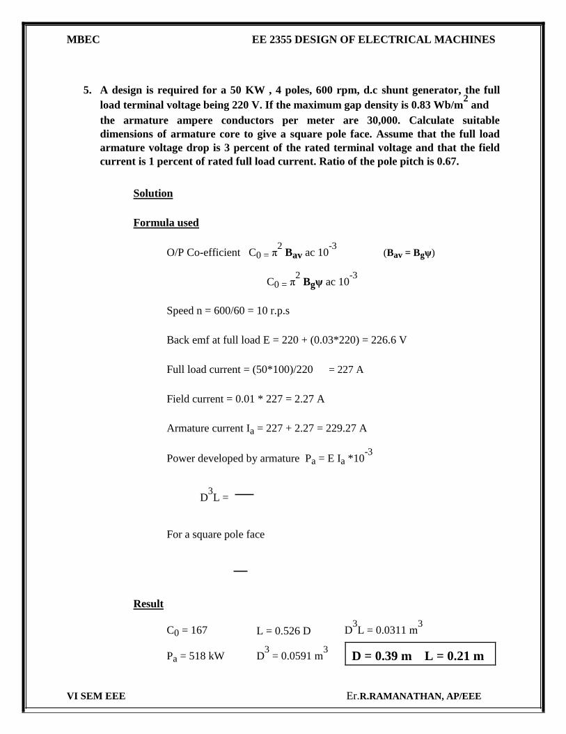
5. A design is required for a 50 KW , 4 poles, 600 rpm, d.c shunt generator, the full
load terminal voltage being 220 V. If the maximum gap density is 0.83 Wb/m2 and
the armature ampere conductors per meter are 30,000. Calculate suitable
dimensions of armature core to give a square pole face. Assume that the full load
armature voltage drop is 3 percent of the rated terminal voltage and that the field
current is 1 percent of rated full load current. Ratio of the pole pitch is 0.67.
Solution
Formula used
O/P Co-efficient C0 = π2 Bav ac 10
-3 (Bav = Bgψ)
C0 = π2 Bgψ ac 10
-3
Speed n = 600/60 = 10 r.p.s
Back emf at full load E = 220 + (0.03*220) = 226.6 V
Full load current = (50*100)/220 = 227 A
Field current = 0.01 * 227 = 2.27 A
Armature current Ia = 227 + 2.27 = 229.27 A
Power developed by armature Pa = E Ia *10-3
D3L =
For a square pole face
Result
C0 = 167 L = 0.526 D D3L = 0.0311 m
3
D3 = 0.0591 m
3
Pa = 518 kW D = 0.39 m L = 0.21 m
VI SEM EEE Er.R.RAMANATHAN, AP/EEE
MBEC EE 2355 DESIGN OF ELECTRICAL MACHINES
UNIT III TRANSFORMERS
PART A
1. What is window space factor in design of transformer?
window space factor It is defined as the ratio of copper area in window to total area of window.
2. What are the advantages of three phase transformers over single phase transformers?
i. A three phase transformers is lighter, occupies lesser space, cheaper and more efficient than a bank of single phase transformers.
ii. In case of three phase transformers than is only one unit to install and
operate. Hence the installation and operational costs are smaller for three
phase units.
3. What are the important properties of transformer steel? Properties
i. High permeability ii. high resistivity iii. low coercive force
4. What are the drawbacks of sandwich winding?
Requires more labour in its maintenance, more difficult to insulate different coils from each other and from yoke.
5. Mention the main function of cooling medium used in transformer. main function
i) To transfer heat from convection from the heated surface to tank surface. ii) To create good level of insulation between various conducting parts.
6. What are the different losses in a transformer? Losses in a transformer:
Core (or) iron loss. Copper loss
VI SEM EEE Er.R.RAMANATHAN, AP/EEE
MBEC EE 2355 DESIGN OF ELECTRICAL MACHINES
7. Why is the core of the transformer laminated?
The cores of transformer are laminate in order to reduce the eddy current losses.
The eddy current loss is proportional to the square of the thickness of laminations. This
apparently implies that the thickness of the laminations should be extremely small in
order to reduce the eddy current losses to a minimum.
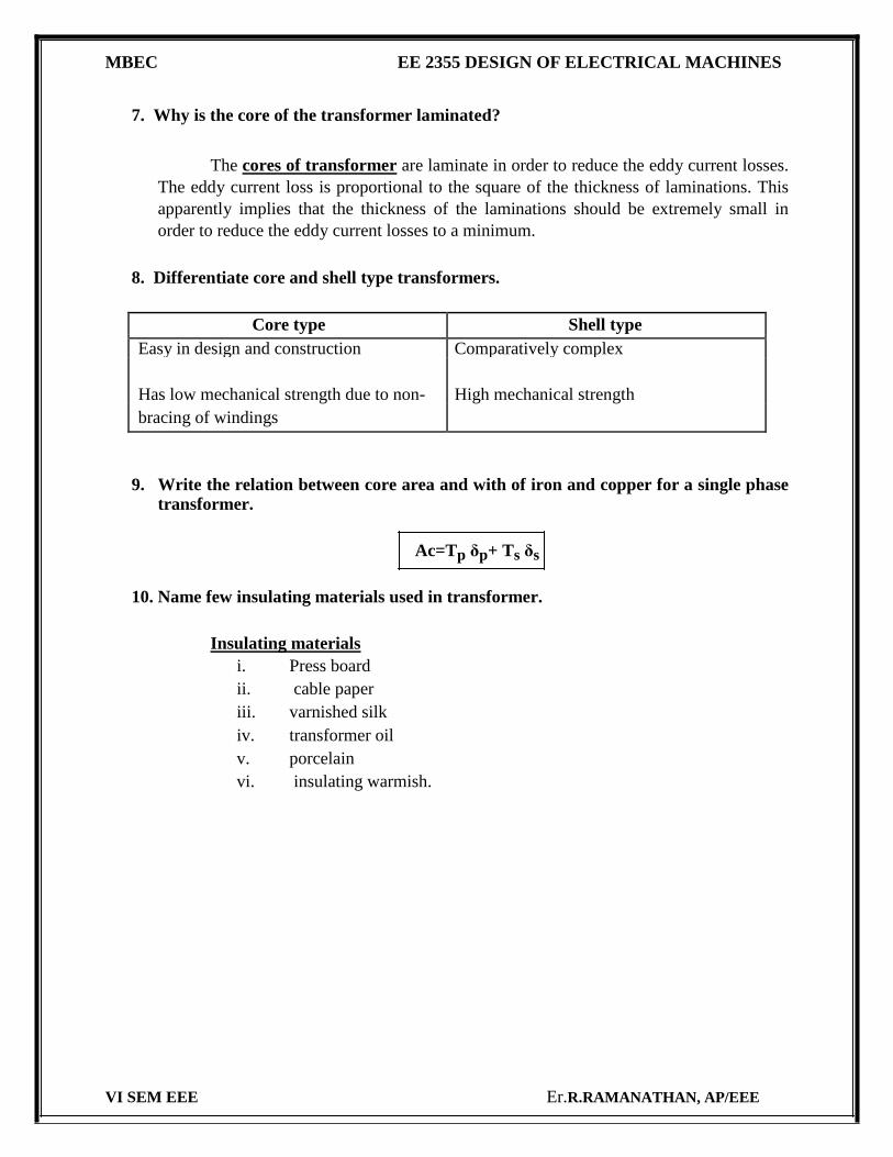
8. Differentiate core and shell type transformers.
Core type Shell type
Easy in design and construction Comparatively complex
Has low mechanical strength due to non- High mechanical strength
bracing of windings
9. Write the relation between core area and with of iron and copper for a single phase transformer.
Ac=Tp δp+ Ts δs
10. Name few insulating materials used in transformer.
Insulating materials i. Press board ii. cable paper iii. varnished silk iv. transformer oil v. porcelain vi. insulating warmish.
VI SEM EEE Er.R.RAMANATHAN, AP/EEE
MBEC EE 2355 DESIGN OF ELECTRICAL MACHINES
PART B
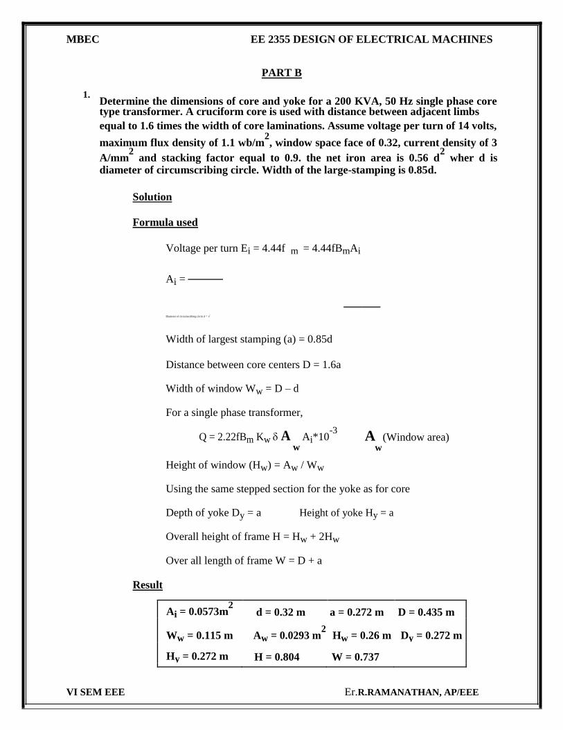
1. Determine the dimensions of core and yoke for a 200 KVA, 50 Hz single phase core
type transformer. A cruciform core is used with distance between adjacent limbs
equal to 1.6 times the width of core laminations. Assume voltage per turn of 14 volts,
maximum flux density of 1.1 wb/m2, window space face of 0.32, current density of 3
A/mm2 and stacking factor equal to 0.9. the net iron area is 0.56 d
2 wher d is
diameter of circumscribing circle. Width of the large-stamping is 0.85d.
Solution
Formula used
Voltage per turn Ei = 4.44f m = 4.44fBmAi
Ai =
Diameter of circumscribing circle d = √
Width of largest stamping (a) = 0.85d
Distance between core centers D = 1.6a
Width of window Ww = D – d
For a single phase transformer,
Q = 2.22fBm Kw A w
Ai*10-3
A (Window area)
w
Height of window (Hw) = Aw / Ww
Using the same stepped section for the yoke as for core
Depth of yoke Dy = a Height of yoke Hy = a
Overall height of frame H = Hw + 2Hw
Over all length of frame W = D + a
Result
Ai = 0.0573m2 d = 0.32 m a = 0.272 m D = 0.435 m
Ww = 0.115 m Aw = 0.0293 m2 Hw = 0.26 m Dy = 0.272 m
Hy = 0.272 m H = 0.804 W = 0.737
VI SEM EEE Er.R.RAMANATHAN, AP/EEE
MBEC EE 2355 DESIGN OF ELECTRICAL MACHINES
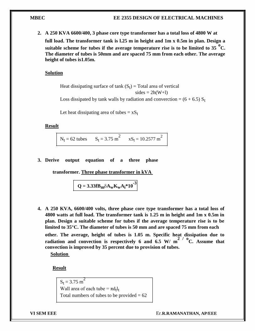
2. A 250 KVA 6600/400, 3 phase core type transformer has a total loss of 4800 W at
full load. The transformer tank is l.25 m in height and 1m x 0.5m in plan. Design a
suitable scheme for tubes if the average temperature rise is to be limited to 35 oC.
The diameter of tubes is 50mm and are spaced 75 mm from each other. The average
height of tubes is1.05m.
Solution
Heat dissipating surface of tank (St) = Total area of vertical
sides = 2h(W+l)
Loss dissipated by tank walls by radiation and converction = (6 + 6.5) St
Let heat dissipating area of tubes = xSt
Result
Nt = 62 tubes St = 3.75 m2 xSt = 10.2577 m
2
3. Derive output equation of a three phase
transformer. Three phase transformer in kVA
Q = 3.33fBmAwKwAi*10-3
4. A 250 KVA, 6600/400 volts, three phase core type transformer has a total loss of
4800 watts at full load. The transformer tank is 1.25 m in height and 1m x 0.5m in
plan. Design a suitable scheme for tubes if the average temperature rise is to be
limited to 35°C. The diameter of tubes is 50 mm and are spaced 75 mm from each
other. The average, height of tubes is 1.05 m. Specific heat dissipation due to
radiation and convection is respectively 6 and 6.5 W/ m2 / o
C. Assume that
convection is improved by 35 percent due to provision of tubes. Solution
Result
St = 3.75 m2
Wall area of each tube = πdtlt Total numbers of tubes to be provided = 62
VI SEM EEE Er.R.RAMANATHAN, AP/EEE
MBEC EE 2355 DESIGN OF ELECTRICAL MACHINES
UNIT IV INDUCTION MOTORS
PART A
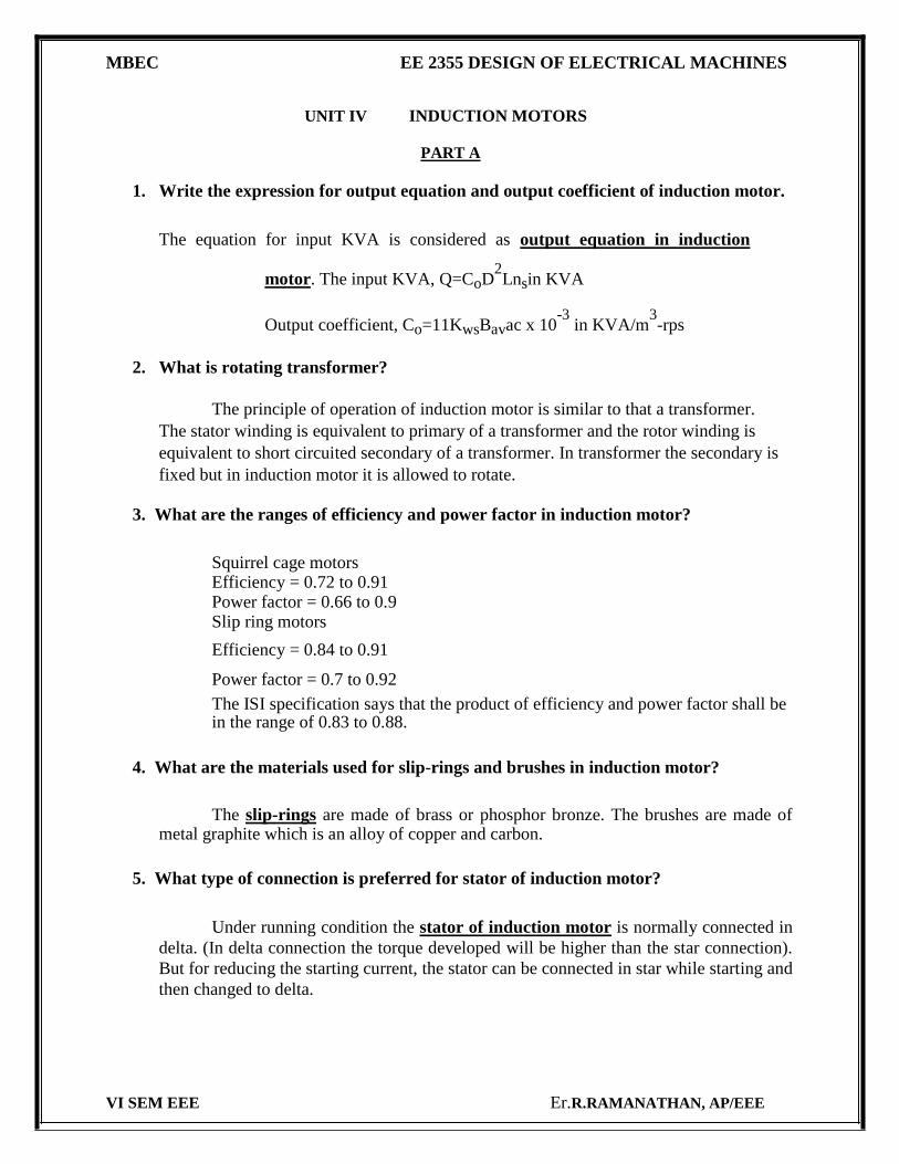
1. Write the expression for output equation and output coefficient of induction motor.
The equation for input KVA is considered as output equation in induction
motor. The input KVA, Q=CoD2Lnsin KVA
Output coefficient, Co=11KwsBavac x 10-3
in KVA/m3-rps
2. What is rotating transformer?
The principle of operation of induction motor is similar to that a transformer.
The stator winding is equivalent to primary of a transformer and the rotor winding is
equivalent to short circuited secondary of a transformer. In transformer the secondary is
fixed but in induction motor it is allowed to rotate.
3. What are the ranges of efficiency and power factor in induction motor?
Squirrel cage motors Efficiency = 0.72 to 0.91 Power factor = 0.66 to 0.9 Slip ring motors
Efficiency = 0.84 to 0.91
Power factor = 0.7 to 0.92
The ISI specification says that the product of efficiency and power factor shall be in the range of 0.83 to 0.88.
4. What are the materials used for slip-rings and brushes in induction motor?
The slip-rings are made of brass or phosphor bronze. The brushes are made of metal graphite which is an alloy of copper and carbon.
5. What type of connection is preferred for stator of induction motor?
Under running condition the stator of induction motor is normally connected in
delta. (In delta connection the torque developed will be higher than the star connection).
But for reducing the starting current, the stator can be connected in star while starting and
then changed to delta. VI SEM EEE Er.R.RAMANATHAN, AP/EEE
MBEC EE 2355 DESIGN OF ELECTRICAL MACHINES
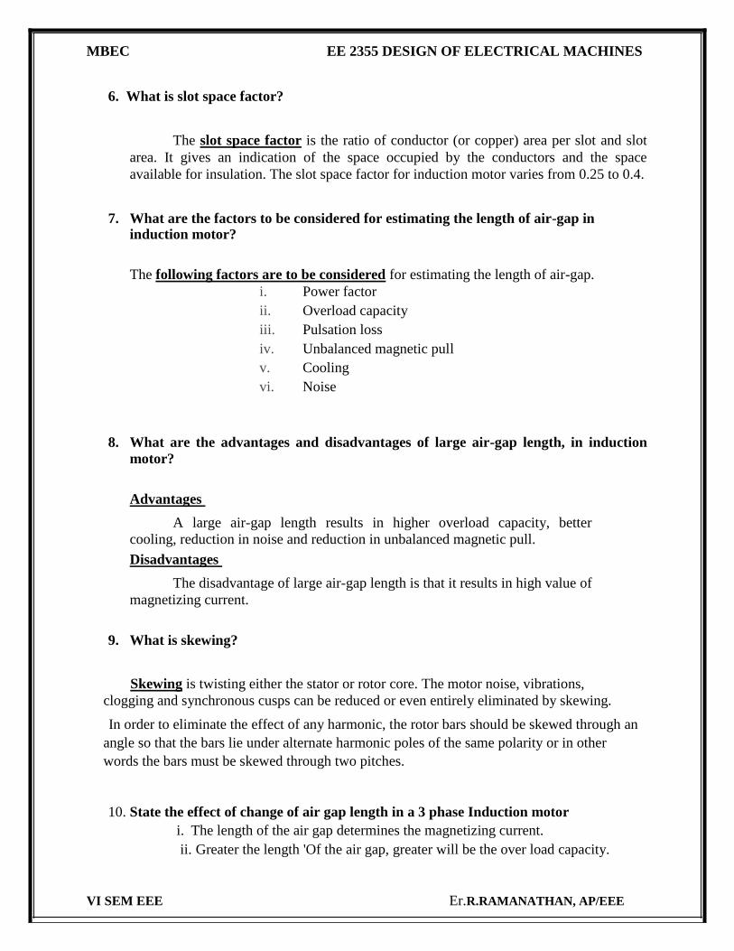
6. What is slot space factor?
The slot space factor is the ratio of conductor (or copper) area per slot and slot
area. It gives an indication of the space occupied by the conductors and the space
available for insulation. The slot space factor for induction motor varies from 0.25 to 0.4.
7. What are the factors to be considered for estimating the length of air-gap in induction motor?
The following factors are to be considered for estimating the length of air-gap. i. Power factor ii. Overload capacity iii. Pulsation loss iv. Unbalanced magnetic pull v. Cooling vi. Noise
8. What are the advantages and disadvantages of large air-gap length, in induction
motor?
Advantages
A large air-gap length results in higher overload capacity, better
cooling, reduction in noise and reduction in unbalanced magnetic pull. Disadvantages
The disadvantage of large air-gap length is that it results in high value of
magnetizing current.
9. What is skewing?
Skewing is twisting either the stator or rotor core. The motor noise, vibrations,
clogging and synchronous cusps can be reduced or even entirely eliminated by skewing.
In order to eliminate the effect of any harmonic, the rotor bars should be skewed through an
angle so that the bars lie under alternate harmonic poles of the same polarity or in other
words the bars must be skewed through two pitches.
10. State the effect of change of air gap length in a 3 phase Induction motor i. The length of the air gap determines the magnetizing current. ii. Greater the length 'Of the air gap, greater will be the over load capacity.
VI SEM EEE Er.R.RAMANATHAN, AP/EEE
MBEC EE 2355 DESIGN OF ELECTRICAL MACHINES
PART B
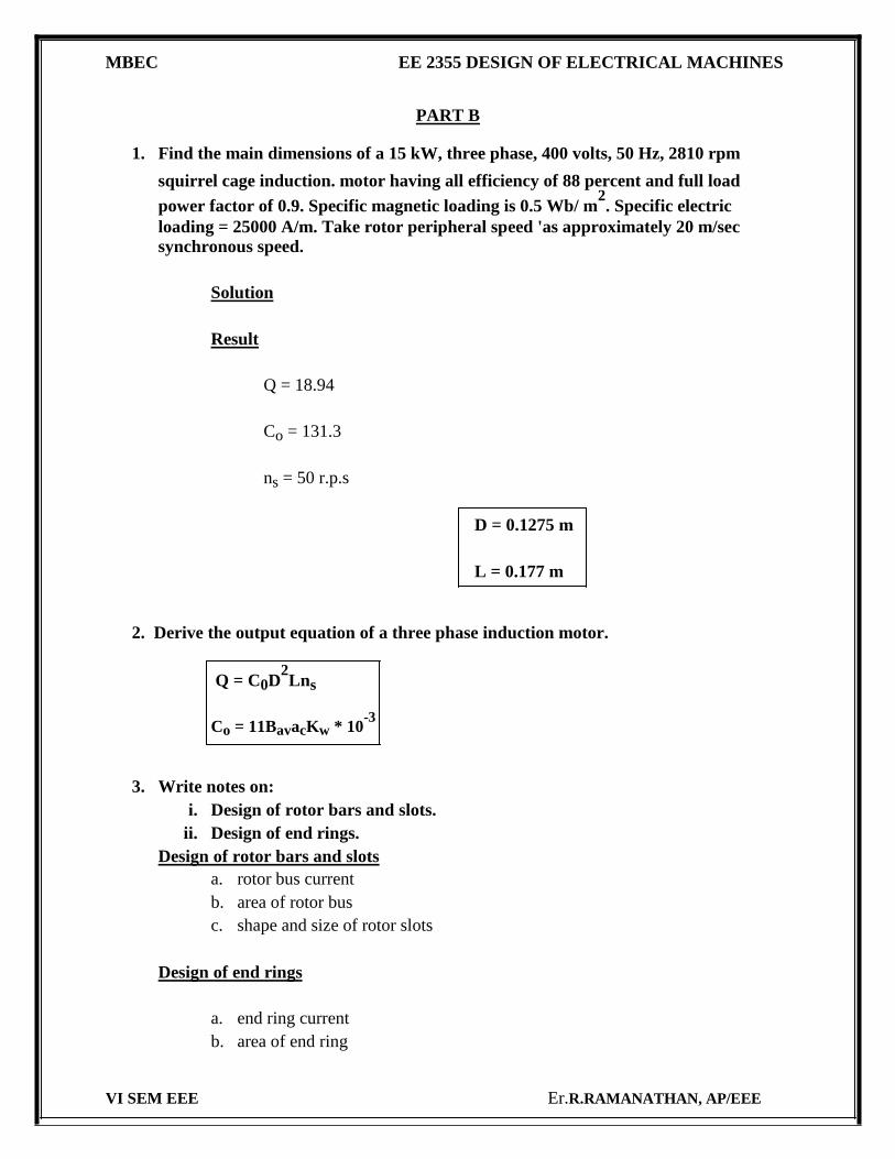
1. Find the main dimensions of a 15 kW, three phase, 400 volts, 50 Hz, 2810 rpm
squirrel cage induction. motor having all efficiency of 88 percent and full load
power factor of 0.9. Specific magnetic loading is 0.5 Wb/ m2. Specific electric
loading = 25000 A/m. Take rotor peripheral speed 'as approximately 20 m/sec
synchronous speed.
Solution
Result
Q = 18.94
Co = 131.3
ns = 50 r.p.s
D = 0.1275 m
L = 0.177 m
2. Derive the output equation of a three phase induction motor.
Q = C0D2Lns
Co = 11BavacKw * 10-3
3. Write notes on: i. Design of rotor bars and slots.
ii. Design of end rings. Design of rotor bars and slots
a. rotor bus current b. area of rotor bus c. shape and size of rotor slots
Design of end rings
a. end ring current b. area of end ring
VI SEM EEE Er.R.RAMANATHAN, AP/EEE
MBEC EE 2355 DESIGN OF ELECTRICAL MACHINES
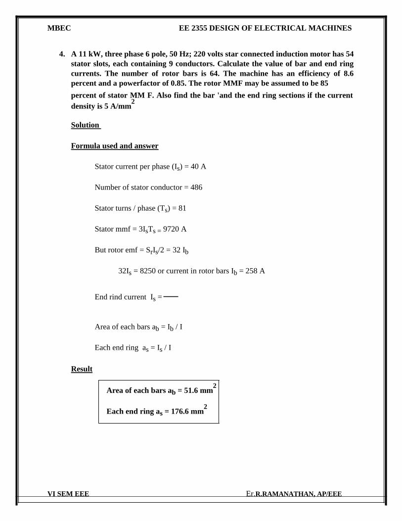
4. A 11 kW, three phase 6 pole, 50 Hz; 220 volts star connected induction motor has 54
stator slots, each containing 9 conductors. Calculate the value of bar and end ring
currents. The number of rotor bars is 64. The machine has an efficiency of 8.6
percent and a powerfactor of 0.85. The rotor MMF may be assumed to be 85
percent of stator MM F. Also find the bar 'and the end ring sections if the current
density is 5 A/mm2
Solution
Formula used and answer
Stator current per phase (Is) = 40 A
Number of stator conductor = 486
Stator turns / phase (Ts) = 81
Stator mmf = 3IsTs = 9720 A
But rotor emf = SrIs/2 = 32 Ib
32Is = 8250 or current in rotor bars Ib = 258 A
End rind current Is =
Area of each bars ab = Ib / I
Each end ring as = Is / I
Result
Area of each bars ab = 51.6 mm2
Each end ring as = 176.6 mm2
VI SEM EEE Er.R.RAMANATHAN, AP/EEE
MBEC EE 2355 DESIGN OF ELECTRICAL MACHINES
UNIT V SYNCHRONOUS MACHINES
PART A
1. Name the two types of synchronous machines.
Based on construction the synchronous machines may be classified as, i. Salient pole machines. ii. Cylindrical rotor machines.
2. What is runaway speed?
The runaway speed is defined as the speed which the prime mover should have, if it is suddenly unloaded, when working at its rated load.
3. What is short circuit Ratio (SCR)?
The Short Circuit Ratio (SCR) is defined as the ratio of field current required to
produce rated voltage on open circuit to field current required to circulate rated current at
short circuit.
It is also given by the reciprocal of synchronous reactance, Xd in p.u (per unit).
For turbo - alternators SCR is normally between 0.5 to 0.7. For salient pole alternator
SCR varies from 1.0 to 1.5.
4. Write the expressions for length of air-gap. in salient pole synchronous machine?
Length of air-gap,
(Or)
VI SEM EEE Er.R.RAMANATHAN, AP/EEE
MBEC EE 2355 DESIGN OF ELECTRICAL MACHINES
5. What are the advantages of large air-gap in synchronous machine?
The advantages of large air-gap are
i. Reduction in armature reaction ii. Small value of regulation iii. Higher value of stability
iv. A higher synchronizing power which makes the
machine less sensitive to load variation. v. Better cooling vi. Lower tooth pulsation loss vii. Loss noise viii. Smaller unbalanced magnetic pull.
6. What is the limiting factor for the diameter of synchronous machine?
The limiting factor for the diameter of synchronous machine is the peripheral
speed. The limiting value of peripheral speed is 175 m/sec for cylindrical rotor machines
and 80 m/sec for salient pole machines.
7. Write the expression for air-gap length in cylindrical rotor machine.
8. Define short circuit ratio of a synchronous gemerator.
The short circuit ratio (SCR) of a synchromous machine is define as the ratio
of field current required to produce rated voltage or open circuit to field current required
to circulate rated current at short circuit.
9. How is computer aided design different from conventional design in the case of electrical apparatus?
i) Easy to access ii) Time consumption iii) Accuracy
10. What are the two types of poles used in salient pole machines?
The two types of poles used in salient pole machines are Round poles and Rectangular poles.
VI SEM EEE Er.R.RAMANATHAN, AP/EEE
MBEC EE 2355 DESIGN OF ELECTRICAL MACHINES
PART B
1. Determine the main dimensions of a 75000 KVA, 13.8 kV, 50 Hz, 62.5 rpm, three phase star connected alternator. The peripheral speed of rotor should be about 40
m/sec. Assume average gap density equal to 0.65 Wb/ m2, ampere conductors per
metre equal to 40,000 and current density =4 A/ mm2. Assume Kw = 0.955.
Solution
Formula used and answer
Synchronous speed ns = 1.0417 r.p.s
Number of poles = 96
Output coefficient = 273
D = 12.2 m
L = 1.77 m
τ = 0.4 m
flux per pole = 0.46 Wb voltage
per phase Eph = 7960 V
With one circuit per phase
Turns per phase Tph = 81.8
Slots per pole phase q = 2.42
2. Derive the output equation of a synchronous machine.
Q = C0D2Lns
Co = 11BavacKw * 10-3
VI SEM EEE Er.R.RAMANATHAN, AP/EEE
MBEC EE 2355 DESIGN OF ELECTRICAL MACHINES
3. Explain the design of turbo-
alternator Design of turbo- alternator
i. Main dimensions
ii. Length of air gap
iii. Stator design
iv. Rotor design
Procedure for rotor winding design
a. Full load field b. Voltage across each field coil c. The length of mean turn d. Total area of field conductors e. Number of field conductors f. Conductors per slot
4. Explain the role of digital computers in the design of electrical machine.
role of digital computer
5. State and explain the salient features of Computer Aided design of electrical apparatus.
Computer Aided design of electrical apparatus
6. State and explain advantages of hydrogen cooling as applied to turbo alternator.
hydrogen cooling as applied to turbo alternator VI SEM EEE Er.R.RAMANATHAN, AP/EEE

Related Documents