! -- > \ EDWARD COHEN Chairman W. C. E. BECKER W. BURR BENNETT, JR. DELMAR L. BLOEM* FRANK B. BROWN T. Z. CHASTAIN ¡ WILLIAM D. CROMAIÚIE OWEN L. DELEV ANTE JAMES N. DE SERIO FRANK G. ERSKINE NOEL J. EVERARD PHIL M. FERGUSON ASHBY T. GIBBONS, JR. WILLIAM A. HEITMANN Reportad by ACI Committee 318 EIVIND HOGNESTAD EUGENE P. HOLLAND FRITZ KRAMRISCH T. Y. LIN MICHAEL A. LOMBARD ROBERT F. MAST ., WILLIAM V. MERKEL ROBERT B. B. MOORMAN KEITH O. O'DONNELL DOUGLAS E. PARSONS EDWARD O. PFRANG W.G. PLEWES RA YMOND C. REESE GEORGE F. LEYH Sacratary THEODORE O. REYHNER PAUL F. RICE FRANCISCO ROBLES PAUL ROGERS JOHN A. SBAROUNIS MORRIS SCHUPACK CHESTER P. SIESS l. J. SPEYER JOHN P. THOMPSON M. P. VAN BUREN A. CARL WEBER GEORGE WINTER ALFRED ZWEIG Because the 1971 ACI Building Code is written as a legal document so that it may be in· corporated verbatim or adoptad by reference in a general building code, it cannot present background details or suggestions for carrying out its requirements or intent. lt is +he function of this Commentary to fill this need. The Commentary discusses some of the considerations of +he committee in developing +he Code with emphasis given too the explanation of new or revisad provisions that may be unfamiliar to Code users. - References to much of the research data referred to in preparing the Code are cited for +he user desiring to study individual questions in greater· detail. Other documents that provide sug- gestions for carrying o.ut the requirements of the Code are also cited. The chapter and section numbering of the Coda are followed throughout. Keyworás: admixtures; aggregates; anchorage {structural); beam-column frame; beams {sup- ports); building codes; cements; cold weather construction; columns (supports); combined stress; composite construction (concrete to concrete); composite construction (concrete and steel); compressive strength; concrete construction; :concretes; concrete slabs; construction . joints; continuity {structural); cover; curing; deep beams; deflections; drawings; earthquake ·: resistan+ structures; embedded service ducts; flexural strength; floors; folded plates; foot- ings; formwork (construction); frames; hot weather construction; inspection; joists; lightweight concretes; loads (forces); load tests (structural); materials; mixing; mix proportioning; mod- ulus of elasticity; moments; pipe columns; ·pipes (tubes}; placing; pn;cast concrete; pre- stressed concrete; prestressing steels; quality control; reinforced concrete; reinforcing steels; roofs; serviceability; shear strength; shear walls; shells {structural forms); spans; specifica- tions; splicing;, strength; strength analysis; structural analysis; structural design; T-beams; tor- sion; walls; wa.ter; welded wire fabric. Copyright© 1971, Amencan Concrete Institute. All r1ghts rescrved lncludlng nghts oJ. reproductlon and use m any fonn or by any means, mcludmg the maklng of cop1es by any photo process, or by any electronlc or mecharucal devlcei prmted or wrttten or oral, or recording for sound or vlsua 1 reproduchon or for use In any knowledge or retrteval system or dev1ce, unless permlssion in wriUng ls obtalned Irom the oopy- rlght proprtetors. The content of thls Cómmentary is the responslblllty of the cornm1ttee whlch prepared 1t. InsUtute authorlty attaches only to standard& adopted as provlded In the Bylaws. i' _ ........ -.; :.

Welcome message from author
This document is posted to help you gain knowledge. Please leave a comment to let me know what you think about it! Share it to your friends and learn new things together.
Transcript
!
--
> \
EDWARD COHEN Chairman
W. C. E. BECKER W. BURR BENNETT, JR. DELMAR L. BLOEM* FRANK B. BROWN T. Z. CHASTAIN ¡ WILLIAM D. CROMAIÚIE OWEN L. DELEV ANTE JAMES N. DE SERIO FRANK G. ERSKINE NOEL J. EVERARD PHIL M. FERGUSON ASHBY T. GIBBONS, JR. WILLIAM A. HEITMANN
Reportad by ACI Committee 318
EIVIND HOGNESTAD EUGENE P. HOLLAND FRITZ KRAMRISCH T. Y. LIN MICHAEL A. LOMBARD ROBERT F. MAST ., WILLIAM V. MERKEL ROBERT B. B. MOORMAN KEITH O. O'DONNELL DOUGLAS E. PARSONS EDWARD O. PFRANG W.G. PLEWES RA YMOND C. REESE
GEORGE F. LEYH Sacratary
THEODORE O. REYHNER PAUL F. RICE FRANCISCO ROBLES PAUL ROGERS JOHN A. SBAROUNIS MORRIS SCHUPACK CHESTER P. SIESS l. J. SPEYER JOHN P. THOMPSON M. P. VAN BUREN A. CARL WEBER GEORGE WINTER ALFRED ZWEIG
Because the 1971 ACI Building Code is written as a legal document so that it may be in· corporated verbatim or adoptad by reference in a general building code, it cannot present background details or suggestions for carrying out its requirements or intent. lt is +he function of this Commentary to fill this need.
The Commentary discusses some of the considerations of +he committee in developing +he Code with emphasis given too the explanation of new or revisad provisions that may be unfamiliar to Code users. -
References to much of the research data referred to in preparing the Code are cited for +he user desiring to study individual questions in greater· detail. Other documents that provide suggestions for carrying o.ut the requirements of the Code are also cited.
The chapter and section numbering of the Coda are followed throughout.
Keyworás: admixtures; aggregates; anchorage {structural); beam-column frame; beams {supports); building codes; cements; cold weather construction; columns (supports); combined stress; composite construction (concrete to concrete); composite construction (concrete and steel); compressive strength; concrete construction; :concretes; concrete slabs; construction . joints; continuity {structural); cover; curing; deep beams; deflections; drawings; earthquake ·: resistan+ structures; embedded service ducts; flexural strength; floors; folded plates; footings; formwork (construction); frames; hot weather construction; inspection; joists; lightweight concretes; loads ( forces); load tests ( structural); materials; mixing; mix proportioning; modulus of elasticity; moments; pipe columns; ·pipes (tubes}; placing; pn;cast concrete; prestressed concrete; prestressing steels; quality control; reinforced concrete; reinforcing steels; roofs; serviceability; shear strength; shear walls; shells {structural forms); spans; specifications; splicing;, strength; strength analysis; structural analysis; structural design; T-beams; torsion; walls; wa.ter; welded wire fabric.
•Dece:~sed Copyright© 1971, Amencan Concrete Institute. All r1ghts rescrved lncludlng nghts oJ. reproductlon and use m
any fonn or by any means, mcludmg the maklng of cop1es by any photo process, or by any electronlc or mecharucal devlcei prmted or wrttten or oral, or recording for sound or vlsua
1
reproduchon or for use In any knowledge or retrteval system or dev1ce, unless permlssion in wriUng ls obtalned Irom the oopyrlght proprtetors.
The content of thls Cómmentary is the responslblllty of the cornm1ttee whlch prepared 1t. InsUtute authorlty attaches only to standard& adopted as provlded In the Bylaws.
i'
_ ........ -.; :.
Committee 318 has f~lt that to be of greatest benefit a Commentáry on the 1971 Code should be available at the same time as final copies of the Code become available. To achieve this, it ~as realized that the work had to be done .concurrently with that on the Code itself and had to be kept up to date as the Code was amended. This could not be achieved entirely with volunteer effort. Noel J. Everard, a member of Committee 318, was commissioned on a consulting basis to prepare a first draft of the complete commentary.
After study and comment by committee members, the subcommittee chairmen were each asked to prepare a second draft for their particular chapters taking into account the comments received.
An editorial task group of George F. Leyh, Ashby T. Gibbons, and Samuel J. Henry prepared three subsequent drafts, each time taking into account tlie comments received on previous drafts and the amendments to the Code which were made as a result of the formal discussion period, further study by committee members, and the discussion ~t the 1970 ACI Fall Convention where the Code was approved for submission to letter ballot of the ACI membership. The editorial task group was assisted at sorne of its meetings by Gordon Plewes and Noel Everard; Richard D. Gaynor acted as Chairman of Subcommittee 4 through the last two drafts after the death of Delmar J... Bloem-. '
This task could not have been completed on ti!me without the dedicated efforts bf the members óf Committee 318, particularly the shbcommittee chairmen as well as the individuals mimed above. · ,' · 1
CONTIENTS
Preface .................................................... 2
' '\
lntroduction ..... _ ........ · ...................... _. ...... _, ..... S
Chapter 1-Ceneral aequirements ... : ~ ~ ....... ' .... _ ............. 6
1.3-Inspection 1.1-Scope , 1.2-Permits and drawings 1.4-Approval of special systems of design or
construction 1'
,: ... -
. ~hapter 2-Definitions ...... ; ............. ; ...... ; ............ 8
Chapter 3-Materials .......................................... 8
3.2-Cements 3.~-Aggrega tes 3.4-Water
3.5-Metal reinforcement 3.6-Admixtures 1
3.8-Specifications cited in the Code '
Chapter 4-Concrete Quality .................................. 11 4.1-General 4.2-Selection of concrete proportions
4.3-Evaluatio'h and acceptance of concrete -References 1
Chapter S-Mixing and Placing Concrete .............. : ........... 14
5.1-Preparation of equipment and place of dePQsit 5.2-Mlxing of concrete -5.3-Conveying 5.4-Depositiríg·
i
5.5-Curing 5.6--Cold weather requirements 5.7-Hot weather requirements
-References
Chapter 6-Formwork, Embedded Pipes, and Construction Joints ....... 16
2 ACI COMMITTEE REPORT
-<{

.,;; ..... Chapter 7-Dctails of Reinforcement .................................................... 16
' -General
7.1 -Hooks and bends 7.2 -Surface conditwn of reinforcement 7.3 -Placing remforcement 7.4 -Spacmg of remforcement 7.5 -Sphces in reinforcement-General 7.6 -Splices in tenswn 7.7 -Sphces in compression 7.8 -Splices of welded plain wire fabric
7.9 -Splices of deformed wire and welded de-formed wire fabric
7.10-Special details for columns 7 .11-Conn ections 7.12-Lateral reinforcement 7.13-Shrinkage and temperature reinforcement 7.14-Concrete protechon for reinforcement
-References
Chapter 8-Analysis and Design-Ceneral Considerations ....... .' ............................. 25
8.1 -Design methods ll 2 -ReqUired loading 3.3 -Modulus of elastlcity 8.4 -Frame analys1s and des1gn-General 8.5 -Frame analysis and design-Details 8 6 -Red1stribution of negative moments m con
tmuous nonprestressed flexura! members
8.7 -Requirements for T-beams 8.8 -Concrete jo1st floor construction 8.9 -Separate floor finish 8.10-Alternate design method
-References
Chapter 9-Strength and Servi.~eability Requirements ....................................... .'29
9.1-General 9.2-Strength 9.3-Required strength
Chapter 1 0-Fiexure and Axial Loads .......... .
10.1 -Scope 10.2 -Assumptions 10.3 -General principies and requirements 10.4 -D1stance between lateral supports of flex-
ura! members , 10.5 -Mmimum 1 emforcement of flexura! sections 10.6 -Distnbution of flexura! reinforcement in
beams and one-way slabs 10.7 -Deep flexura! members 10.8 -Limitmg dimensions for compression mem
bers 10.9 -Limits for reinforcement of compression
members
Chapter 11-Shear and Torsion ......... .
11.1 -General reinforcement requirements 11.2 -Shear strength 11.3 -L1gh t we1gh t concrete shear and torsion
stress es 11.4 -Nommal permissible shear stress for non
prestressed concrete members 11.5 -Nommal perm1ssible sf¡ear stress for pre
stressed concrete members 11.6 -Des1gn of shear remforcement 11.7 -Com bmed torsion and shear for nonpre
stressed members
Chapter 12-Devclopment of Reinforcement
-General 12.1 -Development reé¡uirements-General 12 2 -Posi!Ive moment remforcement 12.3 -Negat1ve moment remforcement 12-% -Spec1al members 12.5 -Development length of deformed bars and
deformed w1re m tension 12.6 -Development length of deformed bars in
compression
i
9.4-De~ign strengths for reinforcement 9.5-Col)trol of deflections
-Re~erences
. . . . . . . . :. ' .. ..................... ' ...... 34
10.10-Slenderness effects in compression members
10.11-Approximate evaluation of slenderness ef-fects '
-Modified R method 10.13-Transmission of column loads through floor
system 10.14-Bearing 10.15-Composite compression members 10.16-Special provisions for walls
-References
. ...................................... 46
11.8 -Design of torsion reinforcement 11.9 -Special provisions for deep beams 11.10-Special provisions for slabs and footings 11.11-Shear reinforcement in slabs and footings 11.12-0penings in slabs 11.13-Transfer of moments to columns 11.14-Special provisions for brackets and corbels 11.15-Shear-friction 11.16-Special provisions for walls
-~,eferences
.............................. : . .... .''57
12.7 -tievelopment length of bundled bars 12.8 -S.tandard hooks • 12.9 -Combinatwn development length 12.10-Development of welded wire fabric 12.11-Development length of prestressing strand 12.12-Mechamcal anchorage 12.13-Anchorage of web reinforcement
-References
Chapter 13-Siab Systems with Multiple Square or Rectangular Panels .................... , ....... 62
13.1-Scope and defmitwns 13 2-Design procedures 13.3-Direct design method 13 4-Equivalent frame method
BUILDING CODE COMMENTARY
13.5-Slab remforcement 13.6-0p'enings m the slab system
-References
3 _j
Chapter 14-W;;ils ................................................................. . 10
14.1-Structural design of walls 14.2-Empirical design of walls
Chapter 1 S-Footings ......... : ......................................... , ............ 70 15.1 -Scope 15.2 -Loads and reactions 15.3 -Sloped or stepped footings 15.4 -Bending moment 15.5 -Shear and development of reinforcement
16.6 -Transfer of stress at base of colwnn or ¡>edestal
15.7 -Pedestals and footings of unreinforced concrete
15.10-Combined footings and mats -References
Chapter 16-Precast Concrete .......................................................... 74
-General 16.1-Scope 16.2-Deslgn
16.3-Bearing and nonbearing wall panels 16.4-Details 16.6-Transportation, storage, and erectioh
Chapter 17-C~mposit~ Concrete Flexura! Me~bers ..... : ................. , , . , , . , , . : . ... , •. 75
17.1-Scope 17.2-General considerations 17 .3-Shoring 17.5-Horizontal shear
17.6-Ties for horizontal shear 17.7-Measure of roughness
-References
' . l ' Chapter 18-Prestress~1d Concrete ....... · ............................... , ... , , .......... 76
18.1 -Scope r¡ 18 .. 2 -General considerations 18.3 -Basic assumpt10ns 18.4 -Permissible stresses in concrete-Flexura!
members 18.5 -Permissible stresses in steel 18.6 -Loss of prestress
· 18.7 -Flexura! strength 18.8 -Steel percentage 18.9 -Mínimum bonded reinforcement require
ments
Chapter 19-Shells and Folded Plate Members
19.1-Scope and definitions 19.2-Assumptions 19.3-General considerations 19.5-Reinforcement requirements
l8.10-Repetitive loads 18.11-End regions 18.12-Continuity 18.13-Slab systems 18.14-Compression members-Combined axial
load and bending 18.15-Corrosion protection for unbonded' tendons 18.17-Grout for bonded tendons · .18.19-Application and measurement of prestress-: ing force : " 18.20-Post-<tensioning anchorages and couplers
......... · ............................. · ...... al 1 ~19.6-Prestressing 19. 7-Construction
-References
,.
_f' 'r ·~
Chapter 20-Strength Evaluation of Existing Structures .. ;1
••••••••••••••••••••••• , •••• , ••••••• &G 20.1-Strength evaluation-General 20.2-General ·requirements for analytical investi
gation 20.3-Generalrequirements for load tests
Appendix A-Special Provisions for Seismic Design
A.l-Scope A.2-Defmi tions A.3-General requirements A.4-Assumptions A.5-Flexural•members of special ductile frames
'20.4-Load tests on flexura! members 20.5-Members other than flexura! members 20.6-Provision for lower load r~ting
•••••• ,
1
••••••••••••••••••••••• •• 1 ••• ~ 1 ••••• 87 A.6-8pecial ductile frame columns subjected to
axialloads and bendin~ A.7-Beam-colwnn connectlons in special ductile
frames ,A.S-Special shear walls . -References ;
1 ndex ......................................... ~ .... , .........•.• , ........... , . , ... 93
4 ACI COMMITTEE RC:PORT
' )
This Commentary discusses sorne of the considerations of Committee 318 in developing the provisions contained in "Building Code Requirements for Reinforced Concrete (ACI 318-71) ," hereinafter called the Code or the 1971 Code. Emphasis is given to the explanation of new or rev1sed provisions that may be unfamiliar to Code users. In addition, comments are included for sorne items contained in previous editions of the Code to make the pr~sent Commentary independent of the Commentary for ACI 318-63. Commen ts on specific provisions are made under the corresponding chapter and section numbers of the Code.
The Commentary is not intended to provide a complete historical background concerning the development of the ACI Code, • nor is it intended to provide a detailed résumé of the studies and research data reviewed oy the committee in formulating the prO:visions bf the Code. However, references to sorne :of the research data are proVlded for those who.'wish td study the background material in depth. 3
As the name implies, "Building Code Requirements for Reinforced Conérete (ACI 318-71)" is mean t to be used as part of a legally adopted building code and as such must differ in forro and substance fro~ docurflents that provide detailed specifications, recorn'ínended practice, complete design proced~res, or 'design aids.
The Code is inten'ded to cover all buildings of the usual types, both large and small. Requirements more stringent than the Code provisions may be desirable for unusual consfruction. The Code and this Commentary cannot rl:!place sound engineering knowledge, experience~and judgment.
A building code ~states Ónly the mínimum requirements necessary to pr,bvide for public health and safety. The A~I Code~ is based on this principie. For any structure, t~e owner or the structural designer may x:equire ,the quality of materials and construction td· be higher than the mínimum reqUirements neces~ary tocprotect the public and stated in the Code. 'However, lower standards are not permitted. ,~
This Commentaty dire~ts attention to other documents that provide sG.ggestions for carrying out the requiremtints aná intent of the Code. However, neither those dO'cuments nor this Commentary are intend1!d as a <part of the Code.
The Code has no legal státus unless it is adopted by government bocfies ha~ng the police power to regulate building cfesign ahd construction. Where the Code has not been ad¿pted, it may serve as a
WILDING CODE COMMENTARY
reference to good practice even though i t has no legal status.
The Code provides a means of establishing mínimum standards for acceptance of designs and construction by a legally appointed Building Official or bis designated representatives. The Code and Commentary are not intended for use in settling disputes between the Owner, Engineer, Architect, Contractor, or their agents, Subcontractors,_ Material Suppliers, or Testing Age]1cies. Other ACI publications, such as "Specifications for Structural Concrete for Buildings" (ACI 301) are written specifically for use as contract documen ts for construction. ' Committee 318 recognizes the desirability of standards of performance for individual parties involved in the contract documents. Available for this purpose are the plant certification programs of the :Prestressed Concrete Institute anti the National Ready Mixed Concrete Association, and the quaÜfication standards of the American Society o~ Concrete Constructors. ~In adaition, "Recomtnended Practice for Inspectlon andl Testing Agencies for Concrete and Steéi As Used in Construction (ASTM E 329-70)" recommend~ performan~e requirements for inspectio:~ and ~sting agencies. . The N a tional Board of Accredita tidn in Co-ncrete (:onstru'ction has been formed to initiate ~ program ol accreditation for testing labbratorie~, contractors·, and concrete suppliers. Thé accredi'tation > e plans have not been formalized as of June 1971 but it áppears that, for testing lab'oratoriés, the kccreditation will be based on ASTM E 329. For ¿ontractors or material suppliers, it likely will be 1 • 1 (
based on a record of satisfactory experience or on the existing qualification standards and 1 plant ~ertific~tion programs. ; , Illustfations of the application OJ. the CQde renuirements in structural design me 1' be fob.nd in ;"1 1 . ' the documents listed in the BibLography that follows: ·
References
l. ACI Committee 340, UUimate Strength Destgn Handbook, SP-17, Amencan Concrete I~stitute, Uetr01t, '1967, V. l, 176 pp.
2. ACI Committee 340, Ulttmate Strength Design 'Handboqk, V. 2, Columns, SP-17A, Atrterican Cbncrete Institut~, Detroit, 1970, 226 pp.
•For a h!story of the ACI Bulldmg Code see Kereke¡;, Frank, and Reld; Harold B., Jr., "Flfty Years of Development ih Bwldmg Code, Requuements for Reinforced Concrete," ACI 1 JOURNAL, 'Proceedmgs V. 50, No. 6, Feb. 1954, p. 441. For a cilscüsslon of code phllosophy see Sless, Chester P., "Research, Bwldmg Codes, and Engineenng Practice," ACI JoURNAL, Proceedmg's V. 56, No. 5, May 1960, p. 1105.
5
3. ACI Committee 317, Rcinforced Concrete Design Handbook-Workmg Stress 1\fethod, SP-3, American Concrete Instltute, Detro1t, 3rd Edlt10n, 1965, 271 pp. (Note: Only those procedures related to the design of beams for flexure without axial load apply to the 1971 Code. Specifically, the column design tables and charts do not apply.)
4. Reese, R. C., Columns by Ultimate Strength Design, Concrete Reinforcing Steel Institute, Chicago, 1967, 213 pp. [Designs are based on ACI 318-63 and may require sorne modificahon to meet the 1971 ACI Code. For instance, the Code changes designs for val u es of P" equal to or lcli18 thon 0.10/6'A~ (llmAllllx1o.lloAd. wtth tlex\.lre),)
5. Reese, R. C., Floor Systems by Ultimate Strength Design, Concrete Reinforcing Steel Institute, Chicago, 289 pp. (Designs are bas'ed on ACI 318-63 and may re-
quire sorne modif¡cation to meet the 1971 ACI Code. Generally, values included will be found to be conservahve with respect to the 1971 Code.)
6. Reese, R. C., CRSI Design Handbook (Working Stress Design), Concrete Reinforcing Steel Institute, ChiCago, Ill., 1965, 389 pp. (Designs are based on ACI 318-63 and may not conform to the 1971 ACI Code. In particular, procedures for column design provided in this manual do not conform to, the 1971 Code.)
7. "Ultimate Strength Design of Reinforced Concrete Columns," Engineer~ng Bulletin EB0009.01, Portland Cement Aapoc1At!on, $kokte, 1989, 49 pp, CNote that the PCA tables do not contain an understrength factor .p, hence Mu/</J and Pu/</J must be used when· designing with these aids.)
CHA~TIER 1-GENERAl RIEQUORIEMIENTS
1.1-Scope
The American Concrete Institute "Building Code Requireinents for Reinforced Concrete (ACI 318-71) ,'; hereinafter referred to as the Code, provides mini~um requirements for any reinforced concrete design or construction that is regulated by a general code of which it forms a part. The Code should supersede conflicting requirements dn concrete design and construction in the general codé.
' •l Prestressed concrete~ is included under the def-
initwn of reinforced concrete. Provisions of the Code apply to prestressed concrete except for those which are stated to apply specifically to nonprestressed concrete.
Appendix A, of tht;l Code contains provisions for design and detailing of special earthquake resistant structures. e
Sorne special• structl:1res involve unique problems which aré not c0vered by the Code. However, many Code provisions, such as the concrete quality and de~ign pr,~nciples, are applicable for these structures.
1.2-Permits a'nd dra,jvings
The provisions regaiding preparation of plans, specifications, abd issu~nce of permits are, in general, consisten { wi th tlaose of most general codes
'1 ' and are intended as suru>lements thereto.
The Code li~ts so~e of the most important items of mformation that should be included on the plans. The 'code dbes not imply an all incluSive list, and iddition.~l items may be required by the Building1 0fficia~.
"Building Official" is the term used by many general codes to identify the person charged with administration ~nd en(prcement of the provisions of the building code. ~ However, such terms as "Building Conimissiol}:er" or "BuÜding Inspec-
S
tor'; are variations of the tit!e, and the term "Building Official" as used in rthe AGI Code is intended to include .those variations as well as others which are used in the sam:e sense.~
The ACI Code accepts well documented computer programs as means of obtaining a"structural analysis or design, in lieu of detailed calculations. The extent of input and output irl!formation req~ired will vary, according, to t~e specific requirements of individual B.jlilding
11 Officials.
HoVJever, when a well documented computer program has been used by the designer, only skeleton data should normally be required. This should consist of sufficient input and output data an~ other information to allow the Building Official to perform a detailed review and make comparisons using another program or longhand calqulations. Input data should' be id en tified as to member designation, applied loads,, and span
1 1 -
len~ths. The related output data shouJd include member designation and the shears, :. moments,
! 1 and reactions at key points in the rspan. For column design, it is desirable tó includ'e moment magnification factors in the output where applicabie.
The Code permlts model analysis to be used to 1 r
supplement structural analysis and design cal-cul~tions. Documentation of th~ model analysis should be provided with the refated calculations. Mo~el analysis is most effective'as a tobl for predicting the behavior of actual
1 structures when
performed by a<1 cngincer or architect having experience in this technique.
1.3, lnspection
1.~.1- Inspection is importan,t. since the proper per~ormance of. the structure depends on construction which accurately repr~sents ~he design
· ' ACI COMMITI,EE REPORT
' ¡ '
..,, ·~
and meets Code requirements, within the tolerances allowed. In the public interest, local building ordinances should require the owner to provide adequate inspection for ·all types of construction.
While the Code requires inspection to be done by a competent engineer or architect, or their representatives, it does not intend to set detailed responsibility in this respect. The clause in Section 103 of the 1963 Code "preferably the one responsible for its design" has been omitted from the 1971 Code because of undesirable legal implications. It obviously would be desirable if inspection of construction were done by or under the supervjswn of th~ engin~er or architect who participated in the design.
When conditions will not permit such an arrangement, the owner mayt provide proper inspection of construction th:rough his architects or engineers or throl!lgh sel{<lrate inspection organizations wlth dem9nstrat~p. capability for performing the inspection operation. The degree of mspection required should be set forth in the
, l contracts between t~e owqer, architect, engi-neer, and contractor. Adequate fees should be prov1ded consistent ~ith th~ work and equipmen t necessary to prpperly :perform the inspection.
While it is recognized tha,t sometimes the inspection is done independent!y of the designer, it lS recommended that. the designer be employed to at least oversee inspecti9n and observe the work to see that his design requirements are properly executed.
By "inspection," the Code. does not mean that the inspector should superv~se the construction. Rather it means that. the op.e employed for inspection sholdd visitJ the p~oject w1th the fre-
:)ry necessary to o,bserve 3the various stages of würk and ascertain tl;lat it 1&.: be:ng done in compllance with contrac;i docu¡;pents and Code requ1rements. The frequency Jshould be at least enough to provide geQ.eral kz;lowledge of each operation, whether this:; be several times a day or once in several days. .: .,
bspection in no way rel~eves the contractor from his obligation to follow the plans and spec:fica tions implici tly and td provide the designated quality and quantity of materials and work- · manship for all job s'tages. The inspector should be present as frequently as he deems necessary to explain and interpret design requirements; to Jucge whether the quality -'and quantity of the wc.rk complies with 'lhe co~tract documents; to co:.msel on posslble ways of 9btaining the desired
~ 11
rcsul ts; to see that tre gen~ral system proposed for formwork appears proper (though it remains
11
BUILDING CODE COMMEijTARY
the contr.1ctors rcspoüsJbÜity to destgn and bulld adequate forms and to leave them in place until it is safe to remove them); to see that reinforcing steel is properly installed; to see that concrete is of the correct quality, properly placed, and cured; and to see that tests for quality control are being made as specified.
The Code prescribes mínimum requirements for inspection of all structures within its scope. It is not a construction specification and any user of the Code can require higher standards of inspection than cited in the legal code if he feels additional requirements are necessary.
Recommended procedures for concrete inspection are given in detail in "Recommended Practice for Concrete Inspection (ACI 311-64)" and ACI Manual of Concrete Inspection, (SP-2).
1.3.2- The term "ambient temperature" me-ans the temperature of the environment tO] whichrthe concrete i's directly exposed. Concre~ temperatures as u sed in this section may be taken as Ethe air1 temperature near the surface of the conct'ete; however, ·during mixing and placing: it is practica! to measure the temperature of the mixture.
f.3.3- A permanent record of inspeétion in~the fotm of a ~ob diary is required by this sectioñ, in case questions subsequently arise concerningJthe structural: elements. Photographs décumenting joo progr~ss may also be desirable.
J
1.4-Approval of special systems of 1design rand construction
Ñew m~thods of design, new materia,ls, and new uses of materials must undergo a pebod of developmen t befo re being specifically cbvered in a Co·de. Hetice, good systems or comporients might be·, excluded from use by implicatiotl if means were not available to obtain acceptance. This' section permits proponents to submit data substantiating the adequacy of their system or componeht to a "board of examiners.'' Such a board shbuld be! created and named in accordance with local laws, and should be headed by a compEhent sttuctural engineer. It is recommencied that all bo:ard me{nbers be directly associated with, :and coÍnpetent in, the fields of structural design or
1 •
construction. ~ r • . for spEtcial systems considered und,er this ~ sec-
tion, specific tests, load factors, deflection limits, ' ~ J l
and other. pertinent requirements shbuld be set ~ 1 'l
b~ the bqard of examiners, and shoulfl be co:psis-teil t wi th Jhe in ten t of the Code.
The pr0visions of this section do not appl;y to model tests used to supplement calculations under Section 1.2.2 or to strength evaluat'ion of ~ist-in'g structures under Chapter 20.
1
7
For consistent application of a code, it is necessary that terms be defined where they have particular meanings in the Code. The definitions given are for use in application of the Code only and do not always correspond to ordinary usage. For example, deformed reinforcement is defined as that meeting Sections 3.5.1, 3.5.6, 3.5.7, or 3.5.8. No other bar or fabric qualifies. This definition permita accurate statement of anchorage lengths. Bars or wire not meeting the deformation requirements or fabric not meeting the spacing requirements are "plain reinforcement,'' for Code purposes, and may be used_ only for spirals.
The use of sand replacement for fine aggregate in lightweight concrete has brought about th~ need for a definition for this type of concrete. The term "sand-lightweight concrete" has generally been used in this case. Partial sand replacement is also used in the sense that all of the fine ag: gregate is nofreplaced by sand. ..
Reinforcedr' concrete has been defined to in:. elude prestre.l¡sed concrete. Heretofore, reinforced concrete and prestressed concrete were often treated as different htaterials. Integration of pro~ vions commoh to bo~h is an effort to avoid over~ lapping and conflictlng provisions. Although thé behavior of a prestrJssed member with unbonded tendons may' vary from that of members with continuously bonded tendons, bonded and unbonded prestressed concrete along with conventionally reinforced toncrete are combined under the generic term "refnforced concrete."
Provisions ifor sorne uses of plain concrete, such as plain con~rete footings, are included in the Code. · ,-
The differ~ptiatio1 between columns and walls is based on the principal use rather than on arbi-
' trary relati<;>nships ~ of height, thickness, and
3.2-Cements
3.2.1-In previous ACI Codes, there was an im~ plied warning tha t ~ special a tten tion should be given to moi,st curing when portland blast-furnace slag cement o~· portland-pozzolan cement is used. Since ~peclfie1d strength requirements for these types d,f cemepts are now the same as imposed on their counterpart portland cements in ASTM C 150,, this a9moniti~m_P,oes-not appear in the 1971 ACI :~ode. e - -
3.2.2 - DE;pending on the circumstances, this provision may simply mean the same type of
a
width. The Code, however, permits walls to be designed using the principies stated for column design, as well as by the empirical method in Chapter 14.
While a wall always separates areas or materials, it may also be used to resist horizontal or vertical forces or bending. For example, a retaining wall or a basemont wall serves to sepiU'Qte sir, water, soil, or other materials, while it may also support various combinations of loads.
A column is normally used as a main vertical member carrying axial loads combined with bending and shear. It may, however, forma small part of an enclosure or separation.
_ The term "compression member" is used in the Code to designate any member in which the primary stress is longitudinal compression. Such a member need not be vertical but may have any directional orientation in s¡iace. Bearing walls ahd columns qualify as compression members un-d,er this definition. 1 l
A number of definitions fot; loads are given in . t:p.is chapter as the Code coritains requirements that must be met at variods load e levels. The terms "dead load" and "live= load" i'efer to the unfactored loads specified or1 define& by the lodi building code. The loads: used to proportion a 1 member for adequate strerigth are defined as "design loads" and are al ways fae!tored loads, usmg the load factors specifiéd in eÍther Section 9~3 or Section 8.10. When th~-' Code tefers to design moments, design shead, etc., their values must be determined using design :loads (with Idad factors). Service loads (loads .Jvithout load fActors) are to be used whe~e stipulated in the dode to proportion or investigate rilembers for atlequate serviceability, such' as in~ Section 9.5, ~on trol of Deflections. ~ l
1
c~ment or it may mean cement frorh the identical so urce. The la tter would ~be thé case if the
• - ,1
standard deviation * of strength tests u sed in es-táblishing the required overdesign vJas based ' one particular type of cemen·t from rone partiL:J-
. 1 lar source. In the case of a plant that has deter-n:Üned the standard deviatiori from tests involving cement obtained from severa! ~~ources, the former interpretation would a?ply.
•See ACI Commlttee 214, "Recommended Practlce for EvaluatlOn of Compresslon Test Results of Fleld Concrete (ACI 214-65)." American Concrete Institute, Detro1t, 1965, 28 pp. (Thls standard also appear in the ACI Manual ot Concrete PracUce.)
ACI COMMITTEE REPORT
. _ .. ---~.3-Aggregates
3.3.1-It is recognized that aggregates conforming to nationally recognized specifications are not always economically available and that, in sorne instances, noncomplying materials have a long history of satisfactory performance. Such nonconformmg materials are permitted with special approval when acceptable evidence of satisfactory performance is provided. It should be noted, however, that satisfactory performance in the past does not guarantee good performance under other cond!tions and in other localities. Whenever possible, aggregates conforming to the designated nationally recognized specifications should be used. _
3.3.2-The size limitations on aggregates are provided to insure proper encasement of bars and to minimize honeycomb. A new provision limits the maximum s1ze of aggregate to one-third of the depth of the slab, as ~ecommended by ACI Committee 301. Note that the limitations on maximum s1ze of the aggregate1 may be waived if, in the judgement of the englneer, the workability and methods of corisohdati'bn of the concrete are such that the concrete dm be placed without honeycomb or void.'ln this·instance, the engineer in charge of inspeetion mnst decide whether or not the hmitabons on ma~imum size of aggregate may be waived:
3.4-Water
3.4.1 - A new provisiori has been added concerning chloride ion content of water (including that portian of the mixing water contributed as free moisture on the aggregates) to be used in prestressed concrete or in concrete with aluminum embedment. No nufnerical quantities are stipulated. It is suggested ihat a chloride ion content greater than 400 or 5·oo ppm might be conSidered dangerous and ACI Committee 222 Corroswn of Metals in Concrete, recommend~ tha t levels well below these válues be maintained 1f practicable. : a '
Chloride ions contamed in the aggregate and in admixtures should be ;considered in evaluating the acceptability of total chloride ion content of the mixing water. '
3.4.2-The method for determining the acceptabllity of nonpotable mixing water is prescribed includmg referenc~ to ASTM e 109 which pre-
'b 1 i , sen es procedures for pre~aring and testing mor-tar cubes. Normally sucli tests will be needed only when satisfactory e~perience with the suspect water is nonexfstent dr inadequate.
1 r. 3.5-Metal reinfofcement~
Extens1ve cons6hdatio~1 of ASTM standards
has permitted siz1:¡plification and shortening of this section from that contained in the 1963 Code
t 3 •
1
BUILDING CODE COM~ENTARY
3.5.1-This section contains two exceptions to the 1968 ASTM specification for remforcmg bars. The first exception requires that for bars with a specifled yield strength, f 11, exceeding 60,000. psi, the stress fv must be measured at a strain of' 0.35 percent. This 1s a change from the 1963 ACI Code, Section 1505 (a), which, for ultima te strength designs only, required either a proof stress at a strain not to exceed 0.30 percent for steels with f 11 in excess of 60,000 psi, or a reduction in usable yield strength.
The 1971 Code continues to exempt reinforcing steels of 60,000 psi or less from the additional proof test on the basis of the results of an extensive series of stress strain tensile tests on Grade 60 reinforcement in the complete range of bar sizes, sampled from all types of producing mi~ls in all areas of the country.
The t~sts were under the sponsQrship of. the American Iron and Steel Institute ahd werJ con-" . cluded 'in 1969. Strengths were measured at strains of 0.003, 0.0035, and 0.005. Arthough ¡·average stn!ngths were well above minimum ~pecified yi~ld strength fv at these sttains, normal ~~catter permitted study of sorne results in tvhich the bárs barely met fv at the ASTM prescribed ~train of 0.005. Stress at 0.003 or 0.0'035 was generally closer to fv than the underweight-understrengtlí tolerances permitted at 0.005 strain under ASTM specifications used in the 1963 ACI Code. ASTM specifications cited in the 1971 Code ~hanged the basis of computing yield strength ~rom actual area (permitted to bes underkeight 3% percent for lots, or 6 percent for indif.ridual oars) tb nominal area, effectively upgrading required 'strengths 3% to 6 percent. It was con~luded 'that no exception to the ASTM spe_'cifica:~ions is required for bars with yfeld strengths .f11 of 60,000 psi or less. , " :. The ~xception was retained for bars with speci:fied fv 'greater than 60,000 psi beduse th~ tests :ctid not)nclude Grade 75 bars, but ~as libetalized to allow the proof stress to be that
1 at a sttain of
~0.0035 fath~r tha~ 0.0030, in reco~nition pf the shape qf remforcmg bar stress-strain curves oh-e , ' J -~erved. 1 The requirement that f 11 ,pe the. stress ,co~resp,endin? to a strain of 0.35 p~rcent 4so apphes t.o plam or deformed wiret if the yield .strength specifled exceeds 60,000. \ , ! . r
.( The ~econd exception to the ASTM Sp~cifica-~tions izc Section 3.5.1 requires that fy1eld stfength -corresP.ond to that obtained using,, tests qf fullsize bars. Tests indicate that standard mil1 specimens show higher strength than ~ests on'· actual reinfor,cement specimens. ¡ This, requirement may be met by various procedure~ including, but not limiterl¡ to: (a) tests
·pn full-size bars or (b) tests on standprdized ~small size turned down specimens,: the results of
9
which can be correlated on an adequate and conservative statistical basis with results of tests on full-size bars. All measurement of yield strength whether by full section testing or by the correlation method of (b), shall be based on the nominal area of the bar.
3.5.2-Plain bars are permitted only for spiral reinforcement, either as lateral reinforcement in columns, as torsional reinforcement, or for confining reinforcement for splices.
3.5.3-Welding of reinforcing bars should not be indiscriminately executed without regard to ' steel weldability and proper welding procedures. When welding is called for, the job specifications should cover these items. The important consideration is that the specified procedure and steel weldability are compatible. AWS Dl2.1 gives authoritative¡ recommended practices on this, includ·ing prttheat and interpass temperatures and types of electrodes for various ranges c;¡f carbon and manganese content. If it is desired to restrict the ste~l chemistry to a given ran'ge to suit a specified procedure, ASTM reinforcing bar specifications for the steel must be supple-men ted to cover this. '
, 1
3.5.10-High strepgth bars for prestressing are defmed by mínimum physical requirements ac-
l . cepted by the Prestressed Concrete Instüute.
1• ~
3.6-Admixtures ' 1 1'
3.6.1-At~~ntion ~s called here to the possible adverse effects of ~xcessive chloride ions in the presence of aluminum, and in prestressed concrete. Admixtures .containing any chloride, other than that ..yhich rljlay be contributed as impurities from ~dmixto/e ingredients, should not be used in prestressed concrete or in concrete which will have áluminum embedments. Research 'in-
, ' dicates that any a:_mount of chloride ion in such concrete may be harmful.
j
3.8-Specification~, cited in the Code
The spec'ificatio~s listed were the latest editwns a t the time ;the Code was prepared. Since these specifications are revised frequently, generally in minor debils only, the user of the Code should check directly with the sponsoring society if it is desir,~d to rejer to the latest edition. ; Standard~ specifi~ations or other material to ¡be
legally adopted by~ reference into a building code must refer¡ to a specific document. This can )be done by s1n;¡.ply usiJlg the complete serial desigration since t,he firs~: part indicates the subject and the second. part tqe year of adoption. All of the documents referred to in other parts of the Code are listed, ~vith th~ title and complete serial ¿esignation in ,Sectioq 3.8. In the other sections of the Code, the designations do not include the date so
'
10
,. that all may be kept up-to-date by simply revising this one section.
ACI publications outline excellent procedures for design and construction but are not in the legal form for direct adoption in a code. For this reason they are listed in the Commentary and not the Code. Detailed recommendations for acceptable practices are available in the following standards, committee reports, and special publications of the American Concrete Institute:
Standards and recommendations*
ACI 211.1-70 Reconunended Practice for Selecting Proportions for Normal Weight Concrete
ACI 211.2-69 Recommended Practice for Selecting Proportions for Structural Light-weight Concret~ r
~CI 214-65 Recommended Practice for Evalua-tion of Compre_ssion T~st Results of
t Field Concrete .1
[ACI 301-66 Specifications 1for St~ctural Con-
r crete for Buildings , r ACI 302-69 Recommended Practic~ for Concrete l. l.
Floor and Slab Construction 'ACI 306-66 Recommended,
1 Pract.Íce for Cold
Weather Concreting · 'A.cr 311-64 Recommended Practice for Concrete
Inspection , ·ACI 315-65 Manual of Standard Practice for De
tailing Reinfotced Concrete Structures
ACI 347-68 Recommended Practice for Concrete Formwork
¡ '
ACI 307-69 Specification 'for thJ Design and Construction of Reinfórced Concrete Chimneys ,1
ACI 506-66 Recommended':Practic~ for Shotcret-
~·ACI 517-70
,'ACI 525-63
· ACI 605-59
ACI 614-59
ing ., Recommended· Practi~e for Atmospheric Pressuf.e Steam Curing Mínimum Requiremebts for ThinSection Precast Conc~ete Construc-tion : ~
'1 Recommended. Practice for Hot
,r
Weather Concreting Recommended· Practice for Measuring, Mixing, ahd Placring Concrete
r )
Committee reports* ·:
Guide for Structural Lightweight Concrete (ACI Committee 213, Aug. 1967)'; _
Structural Plain Concrete j(ACI Gommittee 322, · Apr. 1967) 1
Tentative Recommendations for Pt~stressed Concrete (ACI Committee 323, Jan. 1958)
e "Ail ACl current standards, exce~ ACI 3131 and most current
ACI committee reports appear 1n the ACI Manual of Concrete Practíce. - '
ACi COMMITTEE REPORT
Tentative Recommendations for Concrete Members Prestressed with Unbonded Tendons (ACI Committee 423, Feb. 1969) ·:
Tentative Recommendations ·for Design of Composite Beams and Girder~ for Buildings (ACI Committee 333, Dec. 1960)
Design and Construction of Circular Prestressed Concrete Structures (ACI Committee 344, Sept. 1970)
Deflections of Reinforced Concrete Flexural Members (ACI Committee 435, June 1966)
Deflections of Prestressed Concrete Members, (ACI Committee 435, Subcommittee 5, Dec. 1963)
Allowable Deflections (ACI Comrnittee 435, Subcommlttee 1, June 1968)
Suggested Design Procedures for Combined Footings and Mats (ACI Committee 436, Oct. 1966)
Tentative Recommendations' for the Design of Reinforced Concrete Members to Resist Torsion (ACI Committee 438, Jan. 1969)
Consolidation of Concrete (ACI Committee 609, Apr. 1960) (
Guidc to Joint Sealants for Concrete Structures (ACI Committee 504, July 1970)
Special publications
ACI Manual of Concrete Inspection, SP-2 (Reported by Committee 311, 5th Edition, revised 1967)
Reinforced Concrete Design Handbook, SP-3 (Reported by Committee 317, 3rd Edition, 1965) *
Formwork jor Concrete, SP-4 (by M. K. Hurd under direction of Committee 347, 1969)
Ultimate Strength Design Handbook, V. 1, SP-17 (Reporteg by Committee 340, 2nd Printing, 1968)
Ultimate ·Strength Design Handbook; V. 2, Columns, SP-17 A (Reported by Committee 340, 1970)
Torsion of Structural Concrete, SP-18 (Repo~ted by Conímittee 438, 1968)
¡ •Only those procedures In SP-3 related to the deslgn of beams
tor flexure wlthout axial load apply to this code. Speclf.k:ally, the column deslgn tables and ch.arts do not apply. l
l
CHA~TIER 4-CONC!R}ET!E f.lUAII..U"IrY
The requirements for proportioning of concrete mixes and the cnteria for acceptance of concrete are based on the philosophy that the Code is intended pr!marily to protect the safety of the public. Chapter 4 describes proc~dures by which concrete of adequate quality aan be obtained and provides procedures Jor checking the quality of the concrete during and aftei- its placement in the work. J
4.1-Ceneral
The basic premises governing the designation and evaluation of ~oncret~ strength are presented. It is emphasized that the average strength of concrete produced must always exceed the specified value of fe' that was used in- the structural design phase. This is based on probabilistic concepts, and is in tended to.J insure that adequate strength will be developed iq, the structure.
4.2-Selection of co,ncrete ~proportions Deta1led recommendatiorts for proportioning
concrete are given in the publications, "Recommended Practice for Seledting Proportions for Normal Weight Concrete" ~ACI 211.1) and "Recommended Practice for Selecting Proportions for Structural Lightweight Concrete" (ACI 211.2).
4.2.1-The selected water-cement ratio must be low enough to satisfy both the strength criteria
~
BUILDING CODE COMMENTARY.
(Sections' 4.2.2, 4.2.3, or 4.2.4) and the duraoility requirements (Sections 4.2.5, 4.2.6, and 4.2.7) .tThe Code does not include provisions for especially severe exposures, such as to acids or high temperatures, nor is it concerned with' aesthetical considerations such as surface finishes. Items like these, which are beyond the scope o]; the Code, must be covered in the contract documents. Concrete ingredients and proportions must be selected to,·.meet the minimum requirements stated irt the C9de and the additional reqtFremen,ts of the contract documents.
4.2.2-A significant modifica tion has been made in (the procedure for establish'ing corierete proportions. Emphasis has been placed on the use of trial Batches or experience as the .basis for selecting the required water-cement ratio.
The Code emphasizes a statistical basis for es-, "; 1'
tablishing the average strength req_~;üred to as-s~re attainment of the strength leveldo' tha~ was used in ~he structural design stage. ,1If an a¡pplicable stap.dard devia tion"' for strengt~ tests qf the concretel is known, this establishes i the av~rage strength, level for which the concr~te mu,st be proportic;med. Otherwise, the propq¡rtwns 1 must be selected to produce an excess of av~rage
~
f •see ACl Commlttee 214, "Recom.mended Practice for 1Evaluatlon oí Cclmpress1on Test Results :>f F1eld Concrete (ACI 214-65) ." Ame¡;¡can Concrete Instltute. Detr01t, 1965, 28 pp. (This standard also appears m the ACI M.:~nual oj Concrete Practtce.)
l
11

strength, sufficient to allow for a high degree of variability in the strength tests.
Section 4.2.2.1 refers to the fact that the standard deviation used in the calculation of required average strength must have been developed under "similar conditions to those expected." This requirement is extremely important to assure acceptable concrete. Concrete for background ' tests to determine standard deviation is considered to have been "similar" to that required if it was made with th9 same sén'l¡;¡r"l types gf in .. gredients under no more restrictive conditions of control over material quality and production methods than will exist on the proposed work, and if its specified strength did not deviate more than 1000 psi from the fo' required. A change in the type of concrete or a major increase in the strength level may increase the standard deviation. Such ~ situat~on might occur with a change in type of aggregáte (i.e., from natural aggregate to lightweight aggregate or vice versa) or a change from noniair-entrained concrete to a:irentrained concrete. Also, there may be an increase in standard deviation when the average strength level is ráised by a significant amouht, although the incrément of increase in standárd deviation should be somewhat less than directly proportional to the strength increase. When there is reasonable doul5t, any estimated standard deviation used to calculate the required average strength sliould always be on the conservative (high) side~ 1 r
Standard~ devia~ion may be computed either from a single group of 30 or more successive tests of a given'_ class of concrete meeting the above criteria or from t~o groups of such tests whi~h, taken together, cornprise a total of 30 or more._In the latter case, a·~ "statistical" average value of standard deviation. is to be used, calculated by usual statistical methods. .'
The amo.unts bf which average strength 1':fcr
should exceed th~ specified strength fe' h~Ve been calcul,ated by procedures outlined in the report of ACI C~mmittee 214, "Recommencted Practice for Evalu,ation of Compressive Strength Tests of Field Concrete." The listed values repre-
1 '
sent the highest average values required to meet all three of the foliowing criteria, using the maximum standard deviation from the range shown in each case:
l. a probability Oí less than 1 in 10 that a random individual strength test will be below the specified strength fe' '
2. a prob~bility ~f 1 in 100 that an average of 3 consecutive strength tests will be below_ the speci-fied strength fe' 1
3. a probability ~f 1 in 100 that an individJal strength test will o'e more than 500 psi below the specified strength fe'
12
¡:
Using values of "t'' from Table 4 of the ACI Committee 214 Standard,* formulas for c;,alculating the required average strengths reduce to the following for the respective criteria above:
l. fcr =fe'+ 1.282 C1
2. fcr -- fe' + 2.326 .CJ f ' 1 343 = o+ . (j
Y3 3. fcr = fo'- 500 + 2.326 cr
WhfiX'fl
f cr = average strength to be u sed as the basis for selecting concrete proportions, psi
fo' = strength level used in the design of thc structure, psi, as defined in Section 2.1 o[
the Code (specified fe') a = standard deviation óf individual strength
tests, psi 1
lt can be seen that Criterion 2 always produces a required average strength higher than Criterion l. Criterion 2 will produce a higher required average strength than will Criterion 3 for low to moderate standard deviations, up torabout 500 psL For higher standard deviations, however, Criterion 3 governs, i.e., limiting the expected frequency of tests more than 500 psi below the specified fe' to 1 in 100.
The indicated average strength 1levels are intended to reduce the probability1 of concrete strength being questioned on any of,the followinr; usual bases: (1) too many :tests below specified fe'; (2) strength averaging below specified f! for an appreciable period (thr~,e cons~cutive tests); ,or (3) an individual test b~ing di~turbingly low (more than 500 psi below specified f!) .
4.2.4-Estimation of ther water.:cement ratio from the generalized Table 14.2.4 requires speciaJ permission. This is due to the fact;that different ;combinations of ingredients produce concretes which vary considerably ih strength level at-·
tained at_ a given water-ce~ent raJio. Therefore. a single table relating concrete strepgth to watcrcement ratio must, of necessity, be very conservative. In the interest of efonomy,~ the approximate method should be appli~d only1 for relatively small and unimportant structures. · 1
4.2.5-A table of required air contents for airentrained concrete has beenJincludid in the Code based on "Recommended ~ractice: for Selectin~ Proportions for Normal W~ight Concrete" (ACI 211). The values corresponcí to an ·air content in the mortar phase of the concrete of' about 9 to 10
' '
T' •sec "Recommended Practlce forÍEvaluati¿~ of Compresslon , est Resulta of Fleld Concrete (ACI 214-65)rt
" ' ' ÁCI COMMITTEE REPORT
-.. cll
percent, which has been shown to provide optimum protection against damage from freezing and thawing. The entrained air will not protect coarse aggregates that undergo disruptive volume changes when frozen in a saturated condition.
Note that for lightweight aggregate concrete, the specified concrete strength f/ must be at least 3000 psi, except as provided for in Section 4.2.6.
4.2.7 - The sulfate resisting cement required 1
should preferably be Type y or, if Type V is un-availablc, it should be Type'II. lf ne1ther of thcsó types is available, the cement selected should have a tricalcium aluminate cont(mt of less than 8 percent for moderate sulfate resistance and less than 5 percent for high sulfate resistance. Note that sulfate resisting cement will not increase resistance to sorne chemically aggressive solutions, for example, ammonium nitrate. G['he project specifications should cover all speci~l cases. Although not specifically mentioned in t}1e Code, attention is directed here to numerous researches indicating that the judicious employm,ent of a good quality fly ash (ASTM C 618, Class F) improves the sul-, ¡ fa te resistance of coqcrete. ,
4.2.9 - The procedures of the 1963 Code for establishing permis~ible s~ear stresses and required bar development lengths for lightweight concrete have been, 1modifl~d. Previously, except when low values were qsed, splitting tensile strength tests w~re ~equireq for use in calculating a ratio F.P for estab~ishing the reduction of shear stresses in relation · to those allowed for normal weight concrete. Th~ equiv~lent of tha'" procedure is still permltted, but a more direct approach is also given in the 1911 Code~ Tensile splitting tests are not required if shear, and torsion stresses, cracking moment, modulu~ of rupture, and bar development lengths are b~sed on the reasonable assumption that, for a givez;~ compressive strength, the tensile strength: of lightwe1gh t aggrega te concrete (with or witpout s~nd replacement) is a fixed proportion of that for normal weight con-
,. 1 crete. * The percentage of normal weight concrete shear stress permitfed is 75 if all lightweight aggregate is used, or 85 if natural sand is combined with lightweight coarse raggregate to produce sand-lightweight concrete. 1Linear interpolation is used for partial safld repl!cement of fine aggregate. (See Sections1 9.5.2.2,~11.3, and 12.5(c).) Alternatively, the shear and itorsion stress, cracking moment, modulus oÍ ruptufe and bar development lengths for hghtweight agghgate concrete may be upgraded if tests m~de in iccordance with Section 4.2.9 demonstrate t~at the ~ensile strength is higher than the assurp.ed copserva ti ve percen tages stated above. In a~y cas~ the test for splitting tensile strength is used only for laboratory determmation of Its relations~ip to the compress1ve
•' ~ u
BUILDING CODE COMMENTAR~
strength. It is not intended for control of, or &cceptance of, strength properties of the concrete in the field. If use of the splitting tensile strength of lightweight aggregate concrete yields calculated permissible .shear values greater, or bar development lengths less, than allowed for normal weight concrete, the values for normal weight concrete must be used.
4.3-Evaluation :Jnd ac:eeptance of concrete
Efíort hM boon mndo in tho Codo to provid.t~ n clear-cut basis for judging the acceptability of the concrete as well as to indicate a course of action to be followed when the results of strength tests are questionable.
4.3.1 - Samples for strength tests must be taken on a strictly random basis if they are to measure properly the acceptability of the concrete. The cnoice oftimes of sampling or the batches ofEconcrete to be sampled must be made on the ba~is of enance a~one within the period of placemeíit in order to be representative. If batches to be ~sampled are iselected on the basis of appearance/convemience, or other possibly biased crit'€ria, the statistical cbncepts lose their validity. Obviously, not more than one test (average of two cylinders made ft.om a ~ample) should be taken fr;om a single b~üch, ai}d water may not be added a~ter the,sample is taken.
) 4.3.2 ~ For small quantities of a given class of concrete; the Building Official may waive strength test reql!lirements if adequate evidence of satisfactory strength is provided such as .¡;trengtp test results from the same type of concrete supplied on the sam~ day by the same supplier anp. unde; comparable conditions in other work.
· 4.3.3 -;- A single set of criteria is given for acceptabilíty of strength and is applicable rto all
1
concrete' used in structures designed in accoraance with the 1971 Code, regardless of d~sign method used. The concrete strength is considered ~to be satisfaciory as long as averages of alny three consecutive tests remain above the specified fe' and no fnd1vidtl.al test falls below the specified fe' by more than 50Ql psi. Strength tests failing fo meet these criteria ~ will occur occasionally (prpbably about once in .100 tests) even though strength lev~l and lfnifor~ity are satisfactory. Allowa~ce sho~ld be ,nade for such statistically normal. deviations in ~eciding whether or not the streng~h levelt being producep is adequate. Although cpmpara~le in ~erms ot the probability of failure, tJte criterion of minimup1 individual cylinder strength cf 500 psi less than fe' adapts itself more readily to small
~ j e
•see Hanson, J. A .. "Tens1le Strength and 1DJ.agonahTens1on Res!Stance of Structural Lightwelght Concrete," ACI Jotl'liNAL, Proccedmgs V. 58, No. 1, July 1961, pp. 1-40 (See also Reference 116)
13
numbers of tests than did the ACI 318-63 requirement that "not more than 10 percent of the strength tests shall have values less than the spec-
1
ified strength." For example, if only five tests are made on a small job, it is apparent that, if any of them is more than 500 psi below fa' the criterion is not met. However, in view of the small test population, it is impossible to know whether or not a 10 percent limit on tests below fe' could be achieved.
4.3.4 - Positive guidance has been provided in the Code concerning the interpretation of tests of field-cured cylinders. Researchers have shown that cylmders protected ,and cured to simulate good field practice should test not less than about 85 percent of the standard laboratory moist-cured cylinders. This perc(mtage·has been set merely as a rational basis for judging the adequacy of field curing. The pompadson is made between the actual measured stredgths of companion job-cure& and laboratory-curel:i cylinders, not between johcured cylinders and. the specified value of id'. However, results fo.r the job-cured cylinders ark considered sa tisfactdry if they exceed the specifiéd fe' by more than 500 psi even though _they fail tO reach 85 percent of the strengtn of companion laboratory-cured specimens.
4.3.5 - Instructions have been provided concerning the procetlure to be followed wh~n strength tests havé failed to meet the specified acceptance criteria:· For obvious reasons, thes'e instructions rcannot be dogmatic. The Building O'fflcial must apply jJdgment as to the true signifi-
1 1 r canee of low test results and whether or not they indicate need for co':ncern. If further investigati()n is deemed n:ecessary, such investigation may inelude nonddstructi~e tests, or in extreme cases, strength tests of edres taken from the structure. Nondestructive test~, such as by impact hammer, of the concréte in pl1l.ce may be useful in determihing whether' or not{ a portion of the structure actually contains low strength concrete. Such te~ts are of value .prima¡iily for comparisons within t~e
J oj 11
same job rather than as quantitative measures of strength. For cores, if required, conservatively safe acceptance criteria have been provided which, if met, should assure structural adequacy for virtually any type of construction.u·4 3 Lower strength may, of course, be tolerated under many circumstances, but this again becomes a matter of judgment on the part of the Building Official. When the core tests fail to provide assurance of structural adequacy, it may be practicable, particularly in the case of floor or roof systems, for the Building Official to resort toa load test (Chapter 20) as final arbiter. Short of load tests, if time and conditions permit, an effort may be made to improve the strength of the concrete in place by supplemental wet curing. Effectiveness of such a treatment must, of course, be verified by further strength evaluation using procedures previously d\scussed. t · It should be noted that core tests ha.¿,ing an avera~e of 85 percent of the specified strEhlgth are entirely realistic. To expect cor~ tests tó be equal to fé' is not realistic, since differences in the size of specimens, conditions of opt~ining samples, and procedures for curing do not permit 'equal values
· to be obtained. e i
\ The Code, as stated, concerhs itself with assurihg structural safety, and th~: instruc'tions in Sec~ion 4.3 are aimed at that objective. It is not the function of the Code to assign resp~nsibility for strength deficiencies, whether or not they are such asto require corrective measures. r -
References (
: 4.1. Dikeou, J. T., "Fly Ash :pcreases, Res1stance of Concrete to Sulfate Attack," Research Report No. C-1224, Concrete and Structures Branch, Division of Research, U. S. Bureau of Reclatilation, Jan. 1967, 25 pp.
i 4.2. Bloem, Delmar L., "Conciete StrJngth Measure-ment-Cores Vs. Cylinders," ASTM Preliceedings, 1965, pp. 668-696. l
· 4.3. Bloem, Delmar L., "Conc11ete Strey¡gth in Structures," ACI JoURNAL, Proceedings V. 6p, No. 3, Mar. ~968, pp. 176-187.
j 1
CIHAI?l"IER 5-MDUNG· AN!O P!l.ACDNG CONCR~TIE . '
5.1-Prepafation cif equipment and placing of concrete e 11 )
1 ~ ' This secti,<;m call~ attention to the necessity of
using clean ~equipment and for thoroughly clea!ling forms and rein~orcement before proceeding ,to deposit con~rete. I~ particular, sawdust and wopd blocks that· collect inside of forms should be flushed out, and reinforcement must be thorougb-
14
'•
ly cleaned of mud. Excess water should be re-moved from the forms.
5.2-Mixing of concrete , -' Concrete of uniform and· satisfactory quality requires the materials to be thorouglüy mixed. Th~ hecessary time for mixing will dep·end on many factors including batch size, sti~¡fness of the
1 ~ ••
ACI COMMITTEE REPORT
''

. ~· batch, size and grading of the aggregate, and the efficiency of the mixer.
Excessively long mixing times may grind tlie aggregates, and this should be avoided.
5.3-Conveying
The Code requires that conveying equipment be capable of supplying concrete continuously and reliably under all conditions and for all procedures of placement. Those provisions apply to all placement methods, including pumps, belt conveyors, pneumatic systems, wheelbarrows, buggies, crane buckets, and tremies.
Recent reports have indicated that serious loss in strength of concrete cán result when it is pumped through pipe made of aluminum or aluminum alloys. Hydrogen gas generated by the reaction betwe~n the r cement alkalies and aluminum eroded Úom the interior of the pipe surface has been shown tb cause strength reduction as much as 50 percént. Hence, equipment made of aluminum or aluminum alloys should not be used for pump lines, tremies, or chutes other than short c~utes, s~ch as those used to remove concrete from a truck mixer.
1 l ~1
5.4-Depositing
Rehandling concrete can1 cause segregation of the materials. Hence the Code cautions against this practice. Retempering· of partially set concrete with the addition of: water should not be permitted. This does not preclude the practice, recognized in ASTM C 94, of adding water to m1xed concrete to ~bring ~t up to the specified slump range so long as piescribed limits on the maximum mixing time a~d water-cement ratio are not violated. k '
When placing conditions are difficult, such as m deep or heavily reinfor¡ced members, the use of mortar batches will aido in preventing honeycomb and poor bonding ofi the concrete with the reinforcement. When used,cthe mortar should contain the same ratio; of fin~ aggregate to cement and the same water-cement ratio as the concrete
! to be placed. The .mortar
1 should be placed im-
mediately befare ~epositifg the concrete and must be plastic and neither stiff nor fluid when the concrete is placed.
1
5.5-Curing
In addition to requ1ring a mínimum curing temperature and time in'terval as contained in the 1963 Code, the Code provides a specific criterion in Section 4.3.4; for judging the adequacy of fleld curing. At :the test age for which the strength is specified (usually 28 days), fieldcured cylinders should produce strength not less.
BUILDING CODE COMMENTARY
than 85 percent of that of the standard, laboratory-cured cylinders. For a reasonably correct comparison to be made, field-cured cylinders and companion laboratory-cured cylinders must come from the same sample. Field-cured cylinders must be cured under conditions identical to those OÍ· the structure. If the structure is prote,cted from the elemen ts, the cy linder should be · protected similarly. That is, cylinders related to members: not directly exposed to the weather should be cured adjacent to those members and provided with the same degree of protection and type of curing. Obviously, the field cylinders should not be treated more favorably than the elements they represent. (See Code and Commentary,. Section 4.3.4 for additional information.)
- ' If the field-cured cylinders do not provide
sé!-tisfact9ry strength by this comparispn, me~;;ures should be taken to improve the curing o~ the s~ructur~. If the tests indicate a po~,.sible serious "eficien~y in strength of concrete in ~he stru~ture, cpre tes~s may be required, with or cwithout sup¡:¡lement~l wet curing, to check the stru?tural adequacy, as provided in Section 4.3.5~ ' ' l ·~ 5.5.2, - This section applies whenever an ac-
O!Zlerated curing method is used, wheth~:tr for P.recast ~r cast-in-place elements. The ulijmate cpmpres~ive strength fe' of steam CJ.!red copcrete is not as high as that of similar QoncretEl convinuously cured under moist condiV;ions at, modera te temperatures. Also, the elastic mqdulus E e of steam-cured specimens ma~ vary ( from that of :· specimens moist-cured at !normalt temperatures. When steam curing is to be used, it is
J "-
advisable to base the mix proportions on &team-n ( ,- ~.
~ured teft cy linders. ~ f [ e L
t Accelerated curing procedures require careful '· (
attenti~h to obtain uniform and d~penda~le re-sults. It· is essential that moisture loss durihg the curing process be preven ted. l ' e ,. '
'5.6-Cold weather requirements !J • ~
, Detaq& of approved procedures ¡are available ' . ' ·in "Recpmmended Practice for Cold¡Weath~r Con-creting," (ACI 306) . ~
;5.7-H'ot f
weather requirements E
Detaüs of • f
approved procedures are )
in "Recommended Practice for fiot "Concre~ing," (ACI 605). · ::.: '
,1 l
References
l
~
av~ilable ~eather
•
,, -·
~ 5.1 Newlon Jr., Howard, and Ozol, k, "Delayed Ex·pans!On · of Concrete Delivered by Pu¡npmg 'fhrough ,Alumm~m Pipe Line," Concrete Case1 Study :No. 20; V1rgmiá H1ghway Research Council, Oct. 1969.
15
CHAP"\iiER 6--!FORMWORK, !EM!S~lOD~D r?D~IES, ANíD CONSTRUCü~ON JO~N"ll"S
Because proper design, construction, and removal of forms is an involved subject, only the basic requirements are discussed in this Commentary. For detailed information, the reader should refer to the work of ACI Committee 347 in "Recommended Practice for Concrete Formwotl< (ACI 347·68)" tmd Formwork fgr Concreto, ACI Special Publication No. 4.
In determining the time for removal of forms, considera tion should be given to the construction loads and to the po~sibilities of deflections. Th~ construction loads a.r:e frequently at least as great as the des1gn live loads. At early ages, a structure may be strong enopgh to support the applieq load but may deflect sufficiently to cause perma:: nent damage.
Conduits and pipes not harmful to the concrete can be embedded therein, but the work must be done' in sucl1 a manner that the structure will not be· endan"gered. Empirical rules are given for safe installations for common conditions, but special 1 designs must be made for other than commorl conditions. The contractor should not be permitted to install conduits, pipes,
il
Cenera!
Good structural details have always been vital to satisfactory reinforced concrete structures. Over the years. a standard practice for reinforcement details was de\1-eloped gradually. In the 195'6 Code, the details df connections for structural elements, bar cutolfs, splices, and bar bending were based on a str~ss of 20,000 psi for steel and equal bond in tension and compression varying directly witn concrete strength only. For columns and short spah one-way slabs, higher yield strength steels were permitted with higher workmg stresses under t~e same assumptions for bond.
Since the 1956 Code, ACI Committee 318 has collected reports of previous research and practice with high yield strength steels, suggested new
1
research needed, r~ceived reports on new re-search, and translat_ed the results into new Code provisions which create new standards for de-tails of reinforcemen~. '
The rcscarch findings that bond generalÍ~ vanes \v'ith bar diámeter and stress, tensile or
. ¡ compressive, as we"ll as concrete strength, and that anchorage bon~ is not ~irectly proportionál
16
ducts, or openings that are not shown on the plans or not approved by the architect or engineer.
The Code prohibits the use of aluminum in structural concrete unless it is ef{ectively coated or covered. Aluminum reacts with concrete and, ifi tno ptéséñgc oí chlotidé igña, mny al~o rEu:tct
electrolytically with steel causing cracking and/ or spalling of the concrete. Aluminum electrical conduits present a special problem since stray el~ctric current speeds up th~ adver~e reaction.
For the integrity of the structur~, it is important that all joints be carefully · constructed as and where shown on the plans or called for in the specifications. Any variation therefrom sliould be approved by the architect or engineer.
The delay in placing concrete above columns arld walls is provided to pérmi t the concrete td settle and prevent crackin'g at tlte underside
. of the floor system. The restriction on the location of joints is intended to place the joints Where they will cause the least weal{ness in the structure. 11 •
r
to anchorage length, make pecessa¡y a whole family of new reinforcement detailing standards. 'I;he use of a single bond stress value for all size bars was attractively simple, but has been shown to be incorrect. l
i In Chapter 7, the Code proyides separately for t(msile and compressive splices, siie and yield stress level of bars, smooth and deformed welded wire fabric, wel'ded or mechanically connected tension splices, end-bearing compre§sion splices, concrete area between splices, and splices laterally confined by auxiliary reinforcement, reflecting in each case specific findings fróm research.
Research projects have yiel1ded results responsible for a m;mber of specific Code provisions including bending radii for L#14 an'd #18 bars, spiral spacers, end-bearing bompression splices, ~undled bars, and column ties.
7..1-Hooks and bends
; This section is a consolida tion of prov1s1ons a:ffecting hooks and bends from se~eral sections o,f the 1956 Code. Bending. provisjons for the #14 and #18 bars and the 90 {, deg. stirrup
ACI COMi~ITTEE REPORT
•
.. ' Jr tie hook with a six bar diameter extension were added in 1963.
A number of new provision's are given in the 1971 Code for hooks and bends. Standard hooks are described in terms of the 'inside diameter of bend since this is easier to measure than the radius of bend.
A broad survey of bending practices, a study of ASTM bend test requirements, and a pilot study of bending Grade 60 and Grade 75 #14 and # 18 bars woro c:onaidorod in oatQbliahing tho mínimum diameter of bend for each grade. The primary consideration was feasibility of bending without undue breakage. The provision against hot bending contained in the 1956 Code was relaxed on advice of metatlurgists that proper use of heat would not be unsafe.
The Code user is cautioned_ against combining mínimum diameter ofJ bend With extreme cominations of maximum size bar, mínimum concrete strengths, no lateral ot confii\ing auxiliary reinforcement, and maxin\um ternsne stress in the bars. This is particularly important with #14 and #18 bars. 3
Since sorne ASTM specifications do not provide for bend tests of the bars to 1recommended bend diameters, the designer shoul~ make sure that the bends he calls for can safel1 be made with the grades of steel specifieá. 1
7.1.2-The note on special fhrication appearing in the 1963 Code was tleleted 'since bar sizes #14 and #18 are now comfuonly b~nt cold.
7.1.3.1 For each stze of ~ar commonly used as stirrups or ties, mifimum bend diameters are prescribed based on accept~d- industry practice m the United States:~ Use of the recommended sizes for 90 deg and 135 deg stirrup and tie hooks conforming to 'Sectiort 7.1.1.3 will permit multiple bending on l stand~rd stirrup bending equipment. The 1963 ~ode pelmitted bend diameters as small as two bar d1améters. This mínimum value was increased because it is a far more severe bend than fequired by ASTM bend tests, and could serio~sly d1mage the bars. The 1963 ACI Code anchorage r~quirement that stirrups be hooked tightly ~round longitudinal remforcement has b~en re.yised. (See Section 12.13 1.3.) In actual a~phcatio"n, the 1963 Code section could have requi\:·ed dlfferent diameters and hooks on each end of the same stirrup, and so was seldom specified. ~ ~
1
7.1.3.3 - Welded wire 1 fabric, or plain or ' '(
deformed wire, can be used !1or ties and stirrups. The wire at welded .interseGtions does not have
. A 1 the same umform ductility and bendability as in areas which were not heat~d. These effects of the welding tempera.ture a~e usually dissipated in a distance of apprpximat~ly four wire diameters. Mínimum bend diametrrs perrnitted are in
i BUILDING CODE COMMENTARY
most cases the same as those reqmrcd in the ASTM bend tests for wire material.
7.1.4 - rhis section requires that all bends be made cold unless otherwise permitted by the Engineer. In this sense the Engineer is the engmeer or architect employed by the owner to perform inspection. For unusual bends exceeding ASTM bend test requirements special fabrication may be required. It may be necessary to bend bars that have been embedded in concrete, and it usually is not poeaiblc to provido a pin of tha rninimum diameter specified in the Code a t the poin t of bend. Such bending can not be done without authorization of the inspecting engineer. If he so authorizes he will determine whether or not the bars- can be bent cold without damage or • if heating is necessary. If heating is permitted it must be controlled to avoid splitting of the concrefu or damage to the bars. When bars are ríot embedded ~n thin sections, temperatures ranging fro!h 600 to' 800 F are usually sati¡;factory to pednit ben8ing wfthout damage to the bars or the con-crete. 1
7.2-' -Surface conditions of reinforcement
Specific limits on rust are based' on lat~st tests, plus' a review of earlier tests. and tecominendatlons published by Federal' agen¿ies usi4g con<\rete. Reference 7.1 provides guidahce with regar'd to the effects of rust and mili scale on cbond dharacteristics of deformed ~einfording
i J o '
bar~. Rese1rch has shown that a normal,amoun~ of rus,t incre~ses bond. Normal rough hat}dling g~nerally removes rust which is loose _enough to inj hre bond. '
; , 7 .3-' -Piac(ng reinforcement
) ' 1 '7.:3.1 - Specifications of approveq mater-j.als
anq. descrlption of devices for suppo¡:-ting r~infor¡~ement: (appearing in the 1963 Code) were deleted since specification of required performance was considered sufficient. "Taok" welding (welding crossing bars) can seriously weaken a
·] ·' bar at the point welded by creating a metal-lurgical :p.otch effect. This operatión canl be pe~forme~ safely only when the material we\ded and welding operations are under continuous competent co~trol, as in the manufacture¡ of we~ded wire fabrip. f
7.3.2 -¡ An intermeaiate tolerance ,:was a~ded to provide more uniform effect and tq encourage more realjstic applications and enforcement. The use of higher stresses requires closer limits orl effective dqpth, particularly in shallow memoers, and tolerances ideally should be proportion41 to the depth. However, three fixed 11mits were corisidered more practicable for enfor.cement~and fot simplicity of instructions to fi~ld pl~cing crews.
17
S mee the effecti ve depth and clear concrete cover are components of total depth, the tolerances on these dimensions are directly related. Generally accepted prachce, as reflected in other ACI standards, have established tolerances on total depth (formwork or finish) and fabrication of truss bent remforcmg bars and closed ties, shrrups, and spirals. Bar supports and spacers, factory made to tolerances of a lower order of magnitude, are standard in 1/4 in. increments. Wlwn an aQGUmulation gf toleranges may develop, resulting in excessive reduction of effectlve depth or cover, the Engineer should indicate which dimension is critical. The additional requirement that the cover shall not be reduced by more than one-third of the specified cover is necessary, particularly for the lesser cover permitted in precast construction and shells.
7.3.3- This provísion concetning draped fabríc has remainéd esseh tially unchanged through ' a long senes bf ACF Codes. It permits use of tlie lighter styles of welded wire fabric which are flexible enoú.gh to ·arape between supports to be exempt from requfrements of Sections 12.2 and 12.3. Omission of these anchorage requirements in lightly teinforced, short span slabs (where temperature' and ~hrinkage requirements oftén control the 'miniml!lm amount of reinforcement required) has resuHed in economy without ariy
1 ; )
known adverse e'ffects on structural perfor-manee. 1'
S
7.4-Spacing of reinforcement l. ,] í
7.4.1 - Tfl.e spac,ing limits in this section ha;ve been developed ftom successful practice over many yea~s, remfiining essentially unchanged through IDapY codps. The mínimum limits were established. to permit concrete to flow readily in to spaces, betwe~n bars and between bars and forms with9ut hontycomb, and to ensure against concentrati<=!n of bf-rS on a line that might result in shear or ~hrinka~e cracking.
7.4.2 - 'fhe sucFessful practice of "bundli!1g" standard size barsl for large girders, and labora-, tory tests on bun¡_P.led column bars led to the proviswns for buqdlmg bars in the 1963 Code. The provisi~ns of Jhis sect10n are fundamentally the same as those contamed in the 1963 Code, wlth sorne exceptions. Bond researchi·4 showed tha t bar ~u toffs ·¡ for girders and splices for columns shc;mld be staggered. Bundled bars should be t1ed, w1red, or ibtherwise fastened together 'to ensure remaining fn position whether vertical 'or honzontal. ' < '
A llmita'tion that bars larger than #11 r10t be bundled in bea'ms or g1rders has been added, since the ACI Code applies primanly to buildings. The Umted States·~Bureau of Public Roads design en teria for reiriltorced concrete bridges by
18
, ultimate design7 2 permits two-bar bundies of bars up to #18 in bridge girders or columns, usually more massive than those in buildings. Conformance to crack control requirements in the 1971 Code will effectively preclude bundling of bars larger than #11 as tensile reinforcement. The Code phrasing "bundled in contact, assumed to act as a unit," is intended to preclude bundling more than two bars in the same plane. Typical bundle shapes are triangular, square, or L-shaped patterns fgr three- gr fgyrcbar bYndles. As a practica! caution, bundles more than one bar decp in the plane of bending may not be hooked or bent as a unit. Where end hooks are required, it is preferable to stagger them. Bending and hookihg of bundles must be established "in this manner, even at supports.
7.4.3 - These maximum spacing limits have ~emained essen tially unchanged for . many years, even though extended to m~ssive ~ections with :ff18 bars. e 1
! 7.4.4 - These requirements for mínimum bar spacing like those in Section t7.4.1 were developed óriginally to provide access for com:rete placing in columns. Use of the bar diameter as a factor in establlshing the mínimum spacing permitted extension of the original provision to larger bars.
' 7.4.5 - The Commentary bn Sections 7.4.1 and 7.4.4 is applicable here. Se~ also 'section 7.5.4.
, 7.4.6 - The provisions for~ limiting the spacing fJf pretensioning steel were. in Chapter 26, Pre~tressed Concrete, of the 19_.63 Code. They have peen incorporated in this section of the 1971 Code to consolidate all provisions for reinforcement spacing in one chapter. The requirements are essentially the Jame as in the 1963 Code. 1 ~
', 7.4.7 - When ducts for post-terisioning steel in a beam are arranged closely together vertically provision must be made to prevent the steel, whe~ .tensioned, from breaking through the duct. Hori-1zontal disposition of ducts'. must '1allow proper 1 ' ~
placement of concrete. Generally a· clear spacing 1of one and one-third times the size' of the coarse 'aggregate, but not less than 1 in.;i proves satis'factory. Where concentration of ~teel or ducts 'tends to create a weakened 'plane i~ the concrete ;cover, reinforcement should be pr<;>vided to con' trol cracking.
1 (7 .5-Splices in reinforcement-Ce-'eral
·,
: General provisions are inhuded in this section :for splices of reinforcemen~t as reiated to bond, to overall detailing of structural members and to general specifications. (For rdiscussion on
1 ' bond research, see the Con\mentarly for Chapter 12.) '
ACI COMMITTEE ~EPORT
Because each end of a splice introduces stress concentrations which tend to induce early splitting, splice lengths for elasses B, e, and D splices have been made larger than ordinary anchorage lengths. Restrictions on the width of member or the lateral spacing of splices have been added because sorne mínimum area of concrete is needed between adjacent lap splices for full anchorage capacity to be developed. (The two bars that forro a lap splice can be in contact or spaced, as desircd, but must conform to Section 7.5.4.) When the lateral spacing between lap splices is more than 6 in. and the splice is located further than 3 in. from an edge, the developmen t length, ld, may be multiplied by 0.8 [see Section 12.5 (d)], and splices are likewise shortened. Shortening is allowed in this case because of less tendency to split in the plane of the bars.
For ductllity, lap splices sh~uld be adequate to r. develop more than the yield strength of the steel; otherwise, a m~mber is subject to sudden splice failure when ·~he yi~~d strength of the steel is reached and rio "toughness" is obtainable in the member. The lap splic~; lengths specified in the eode satisfy this ductility requirement.
Splices should, if possible, be located away from points of maximum ten:;ile stress. The eode encourages th1s practlce by increasingly severe requirements for splices at higher stress and for splices bunched unfavorably. ~
7.5.1 - The eode requires~ all welding of reinforcement to conform to A WS D12.1 (see eode Section 3.8.2). Primarily, thése requirements demand tha t the chemical analysis of the reinforcement be secured and ~that t~e entire welding operation, including method, material, amount of preheat, if any, etc., be compatible with the chem-cal analysis. ~
~
7.5.2- Research 011: lap splices of #14 and #18 bars is limited. There are ¡Jinsufficient data to establish lap lengthsl for ei'ther tensile or compressive lap splices for #14 or #18 bars. eompression splices of #14 or ~#18 bars to smaller bars used as dowels into ~ootings are allowed. (See eode Section 15~6.8.)
7.5.3- The increased length of lap required for bars in bundles is básed ori~ the reduction in the exposed perimeter of,the bars.
7.5.4 - If individual ba~s in noncontact lap splices are too widely sp~ed, an unremforced section is created. Forcmg the potential crack to follow a zigzag line (5 to l slope) is considered
E ~ a rn1mmum precaution. Th~ 6 in. maximum spac-
1• ~
ing 1s added beca use most ,research available on the lap splicing of
1 moderp deformed bars was
conducted with reiJlforcement which was within this spacing. ·
BUILDING CODE CQ;f!MEN í'A~Y
7.5.5.1 A full welded splice, which is defined in this section, is primarily in tended for .large bars (#6 p.nd larger) in main members. Tlie mínimum tensile capacity required will ensu,re somjd welding, adequate also for compression. The requirement of 125 percent of spec1fied yield strength was contained in the 1963 eode. It is desirable that splices be capable of developing the ultimate strength of the bars spliced, but practica! limitations make this ide~l condition difficult to attain. The maximum reinforcement stress used in design und.er the Code is the yield strength. To ensure sufficient capacity in splices so that yielding can be achieved in the member and thus brittle failure avoided, the 25 percent increase beyond th~ specified yield strength was selected as both an adequate mínimum for safety and a practicable maximum for economy.
·¡ 7 .5.5.2 ~Full posi ti ve conr.~.ections ar+e also =requiÍ·ed to d1evelop 125 percent of the yield strength, in ;tension· or compression as requireO., for the sarlle reashns as given for full welded splicesl in the' eomm~ntary for Section 7.5.5.1. b
J 7.5.5.3 The use of welded splices 'or positive corlnections of less capacity than 125 'percent of yield strerlgth is permitted if the minitilum design cri'teria ofl Section 7.6.3.2 are met. Thérefore, 'ilap we<Ids of reinforcing bars, either with ror witl\out backup mkterial, welds to plate connections, :l:lnd entl-bearil).g splices are allowed unáer certrun cohditiod.
7.6-Spli¿es in tension ~ ; 1
'¡!:'his se~tion consolidates material frQm the ~963 e~de an~ provides new considerations related to the development length concept. (qee ehapter 12jof the ~ode and eommentary.)
1
.Development lengths, Zd, for tens~on bars in nc¡>rmal 'Veight concrete are given in. ehapte,r 12.
:For ligptweight cbncrete and sand-lightweight concrete, the multipliers in ehapter ,12 mu~t be u~ed. Spl~ces are classed as Types A, B, e, aqd D, and multtipliers of lct for various cla~ses are~provi}ied in tSection 7.6.1. Note that Cla?s D splices ~ust be 'enclosed within a spiral conformiqg to S~ction 12.5 (d). The various tensio~ lap splice cqnditions are summarized in Table 7rl. ·1
rThe spjice requirements for situations described in1 Sectións 7 .6.2 and 7 .6.3 were established to p~rmit nj.aximum ecopomy consistent with a uniform structural capacity for the ovetall member. s'pirals ¿round splices greatly mcrea~e resisknce against ¡splitting and improve spli~e strehgth. S'tirrups¡ or ties, unless closely spaced, are' only partially, effective for this purpose. : .,
The requirements in this section ~pply tó tensile spl{ces where tension is the critica! §tress éondition. Thus, the term "regions of maxlmum ) "
z:noment, or high computed stress" i$ inten4ed to ' 1
19
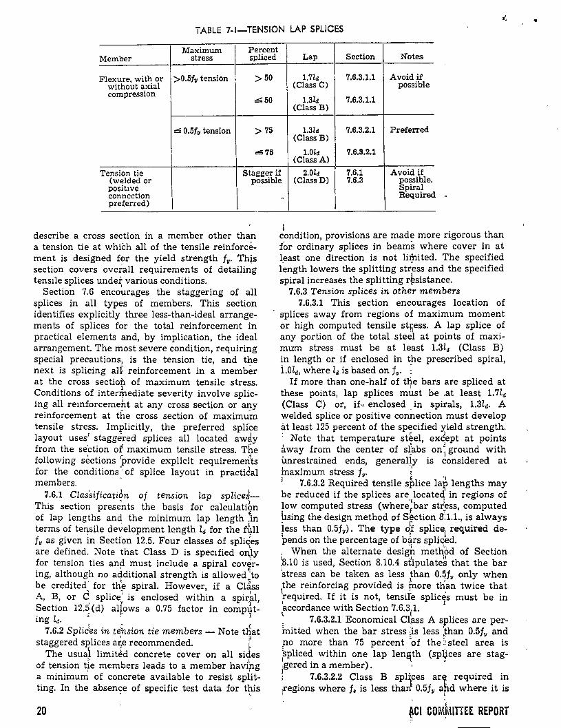
iABLE 7-1-TENSION LAP SPLICES
Maximum Percent Member stress spliced Lap Section Notes
Flexure, with or >0.5/11 tension ·>50 1.7ld 7.6.3.1.1 Avoid if without axial (Class C) possible compression
~50 1.3ld 7.6.3.1.1 (Class B)
::::: 0.5/11 tension > 75 1.3ld (Class B)
7.6.3.2.1 PrefeiTed
.:!$ 75 l.Old 7.6.3.2.1 (Class A)
Tension tie Stagger if 2.0Zd 7.6.1 Avoid if (Class D) 7.6.2 possible. (welded or possible
S piral posit1ve connection preferred)
describe a cross section in a member other than a tension tie at which all of the tensile reinforcement is designed f~r the yield strength f11• Th!s section covers overall requirements of detailing tens1le splices undet various conditions.
(
Section 7.6 encourages the staggering of all splices in all types of members. This section id en tifies explicitly three less-than-ideal arrangements of splices for the total reinforcement in practica! elements and, by implication, the ideal arrangement. The most severe condition, requiring special precautions, is the tension tie, and the next is splicing aü reinforcement in a member at the cross section of maximum tensile stress.
1 Conditions of intennediate severity involve splic-ing all remforcement at any cross section or any reinforcement at the cross section of maximuÍn tensile stress. Implicitly, the preferred splice
• ' 1 layout uses1 staggered splices all located away from the se'ction of maximum tensile stress. The following sections 'Provide explicit requiremen~ts for the coriditions ·. of splice layout in practidal members.
7.6.1 ClassificatiÓn of tension lap splicdThis section prese'nts the basis for calculatibn of lap lengths and the mínimum lap length \n terms of te~sile deVelopment length ld for the t4n fu as given in Secti'on 12.5. Four classes of spliées
' are defined. Note that Class D is speclfied only for tension ties and must include a spiral cov~ring, although no a4ditional strength is allowed ~to be credi ted. for th'e spiral. However, if a Clé'iss A, B, or C splice1 is enclosed within a spirkl, S ' " 1 ection 12.5 (d) allows a 0.75 factor in comput-ing ld. " r 1
7.6.2 Splic'es in Úhsion tie members- Note t~at ' 3 staggered splices ar.e recommended. ,
The usual limitJd concrete cover on all sides of tension t~e members leads to a member havipg a mínimum of concrete available to resist splitting. In the. absen9e of specific test data for t~is
20
Required
1 condition, provisions are made more rigorous than tor ordinary splices in beams where cover in at l_east one direction is not litJlited. The specified length lowers the splitting stress and the specified spiral increases the splitting r~sistance.
7.6.3 Tension splices in other members 7.6.3.1 This section encourages location of
splices away from regions of maximum moment or high computed tensile st~ess. A lap splice of any portion of the total steel at points of maximum stress must be at least 1.3ld (Class B) in length or if enclosed in the prescribed spiral, i.Old, where Zd is based on f11• ;
If more than one-half of the bars are spliced at 1
these points, lap splices must be .at least 1.7ld (Class C) or, if~ enclosed _in spirals, 1.3ld. A welded splice or positive connection must develop at least 125 percent of the specified y-ield strength. ' f l · Note that temperature steel, except at points away from the center of sl~bs on~ ground with imrestrained ends, general~y is considered at 1 • t f ' max1mum s ress 11• 1
' 7.6.3.2 Required tensile splice la? lengths may be reduced if the splices are}ocateq in regions of low computed stress (where~bar stress, computed hsing the design method of Section a:1.1., is always iess than 0.5f11). The type df splice. required de~ends on the percen tage of b~rs splic~d. . When the alternate design meth.?d of Section ;s.10 is used, Section 8.10.4 sÚpulates that the bar stress can be taken as less than O.qf11 only when
1the reinforcing provided is fnore th.an twice that required. If it is not, tensire splices must be in 'accordance with Section 7.6.3.1. r
~ 7.6.3.2.1 Economical Cl~ss A splices are permitted when the bar stress :is less :than 0.5fv and po more than 75 percent 'of the 2 steel area is 'spliced within one lap len~th (spl}ces are stag-~gered in a member). · -! 7.6.3.2.2 Class B spl~ces art required in ¡regions where f, is less than 0.5f11 a~d where it is
' '
~CI COM~ITTEE REPORT r
•
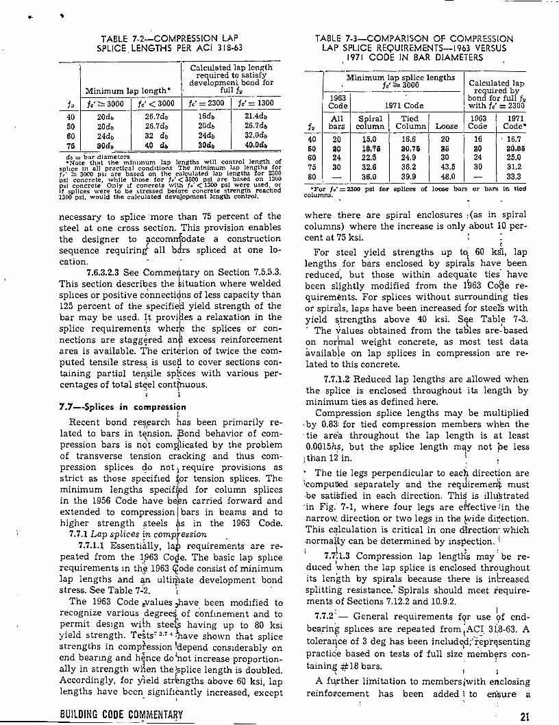
TABLE 7-2-COMPRESSION LAP SPLICE, LENG THS P1~R ACI 318-63
Calculated lap length required to satisfy
development bond for Minimum lap length • full fu
f---fe'= 2300 fe'= 1300 fu fe'~ 3000 fe'< 3000
40 20db 26.7db 16db 21.4db 50 20db 26.7db 20db 26.7db 60 24db 32 db 24db 32.0db 79 30dg 40 Gb 30Gb 40.0Gb
- --d• = bar d!ameters •Note that the mimmum lap lengths wlll control length of
splice m al! practica! cond1t!ons The m!n!mum lap lengths for fc' ~ 30CQ ps1 are based on the calculated lap lengths for 2300 psi concrete whlle those for t• < 3000 psi are based on 1300 psi concrete' Only lf concrete w!th f•' < 1300 psi were used, or !f spl!ces wcre to be ~tressed before concrete strength reached 1300 psi, would the calcul~ted deve!opment length control.
necessary to splice ·more than 75 percent of the steel at one cross section. 'This provision enables the designer to accomnfodate a construction sequence requiring< all bJrs spliced at one location.
7.6.3.2.3 See Comme~' tary on Section 7.5.5.3. This section describes the ituation where welded sphces or positive c~nnecti ns of less capacity than 125 percent of the specifiea yield strength of the bar may be used. It provi~es a relaxation in the
• 1
splice requirements whe~ the splices or con-nections are stagg~red an~ excess reinforcement area is available. The criterion of twice the computed tensile stres~ is use~ to cover sections containing partial ten,sile sp~ces with various percentages of total st~el cont;nuous.
é l •'
7.7--Splices in compression t.
Recent bond re~,earch has been primarily re-lated to bars in tension. Bond behavior of compression bars is n6t comii,icated by the problem of transverse tension cracking and thus compression splices qo not ~ require provisions as strict as those specifled rr tension splices. The mínimum lengths speciffd for column splices in the 1956 Code have beren carried forward and extended to compression 1 bars in beams and to higher strength steels as in the 1963 Code.
7.7.1 Lap splices {n compfession 7.7.1.1 Essentially, lap requirements are re
peated from the ~¡963 Co~e. The basic lap sphce requirements m th~ 1963 ~ode consist of mínimum lap lengths and ~n ultitf:tate development bond stress. See Table 7.:2. '1 ,
The 1963 Code nvalues ;,have been mod1fied to recognize various degreet' of confmemen t and to permit des1gn wÜh stee having up to 80 ksi yield strength. TeSts' 3 ·7 ~ • ave shown that splice strengths in comptession ldepend cons1derably on end beanng and hence do ~ot in crease proportionally in strength w~en the lsplice length is doubled. Accordingly, for yield str~ngths above 60 ksi, lap lengths have been signiflcantly increased, except - ,,
BUILDING CODE COMMENTA~Y
TABLE 7-3-COMPARISON OF COMPRESSION LAP SPLICE REQUIREMENTS-1963 VERSUS
1971 CODE IN BAR DIAMETERS
' Minimum lap splice lengths Calculated lap
' fe'~ 3000 required by
1963 bond for full fu Code 1971 Code with fe'= 2300
All Spiral Tied 1963 1971 fu bars column Column Lo ose Code Code•
40 20 15.0 16.6 20 16 ' 16.7 liO a o 11l.'76 30,76 36 llO g{),!)ij
60 24 22.5 24.9 30 24 25.0 75 30 32.6 36.2 43.5 30 31.2 80 - 36.0 39.9 48.0 - 33.3
•For fe'= 2300 psi tor spllces of loose bars or bars: in tled columns,
where there are spiral enclosures 1 (as in spiral columns) where the increase is only about 10 per-cent at 75 ksi. ·
(
For steel yield strengths up tq 60 ksi, lap lengths for bars enclosed by spirals have been reduced-, but those within adeqUéite ties- have been sl~ghtly modified from the ÜJ63 Co~e requirements. For splices without surrounding ties or spira:is, laps have been increased for steefu with yield ~trengths above 40 k si. S1e Tabl~ 7-3. ' The values obtained from the taoles are- based on nor'mal weight concrete, as most test data availab~e on lap splices in compression are related to this concrete.
7.7.1.2 Reduced lap lengths are -allowed when ,the splice is enclosed throughout its length by mínimum ties as defined here.
Compression splice lengths may be multiplied ·by 0.83: for tied compression members when the tie are"a throughout the lap length is at least 0.0015h~, but the splice length ma¡y not pe less
¡ than 12 in. j
' The tie legs perpendicular to each direction are lcomputJed separately and the reqJiremen~ must ·be satisfied in each direction. This is illustrated ·¡n Fig: 7-1, where four legs are effective ~in the narroW. direction or two legs in the ~ide di~ection. This calculation is critica} in one d~rectiorr which
1 t -normaWy can be determined by msp·ection. 1 , 1
7.7·.1.3 Compression lap lengtlis may be re-duced ~when the lap splice is enclosed throughout its length by spirals because there is inbreased splitting resistance: Spirals should meet requirements of Sections 7.12.2 and 10.9.2.
r 1 7.7.2:- General requirements fqr use <;>f end-
bearin~ splices are repeated from ;ACJ_ 31,8-63. A tolera11ce of 3 deg has been included/rep-r~"senting
\ ~ . '1
practic~e based on tests of full size meinb~rs con-tainin~ # 18 bars. ; ,1
A fu;rther limitation to members!with enclosing reinfo11cement has been added ¡ to erfsure a
21
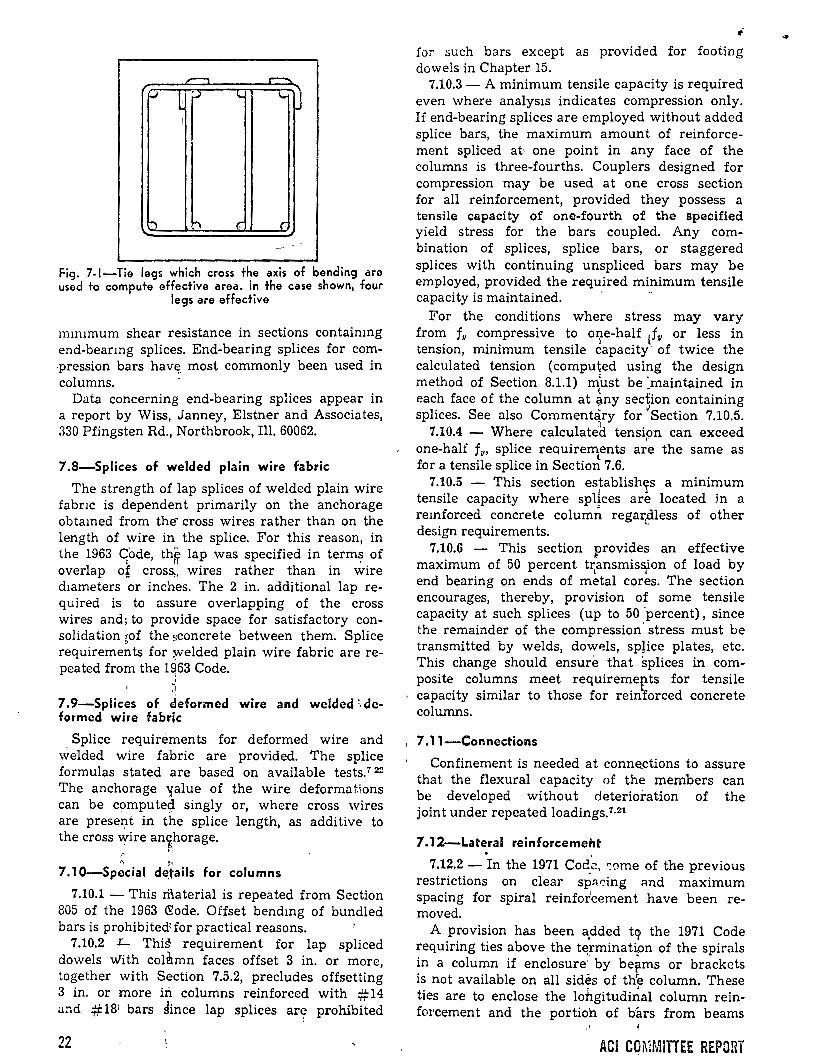
_...., .---f../ L ;..; lo. ~o
!
~ h e (:
Fig. 7-1-Tie legs which cross the axis of bending are used to compute effectiva area. In the case shown, four
legs are effective
muumum shear resistance in sections containmg end-bearmg splices. End-bearing splices for com·pression bars hav~ most commonly been used in columns.
Data concerning end-bearing splices appear in a report by Wiss, Janney, Elstner and Associates, :330 Pfingsten Rd., Northbrook, Ill. 60062.
7.8-Splices of welded plain wire fabric
The strength of lap splices of welded plain wire fabnc is dependent primarily on the anchorage obtamed from the- cross wires rather than on the length of wire in the splice. For this reason, in the 1963 c¡ode, th~ lap was specified in term~ of overlap o~ cros5:, wires rather than in wire d1ameters or inches. The 2 in. additional lap required is to assure overlapping of the cross wires and; to provide space for satisfactory consolidation ~of the sconcrete between them. Splice requirements for ~elded plain wire fabric are repeated from the 1~63 Code.
i 7. 9-Splices of cleformed wire and welded :, deformed wire fabrlc
. Splice requirements for deformed wire and welded wire fabric are provided. The splice formulas stated are based on available tests.' 22
The anchorage 'falue of the wire deforma tions can be C!Jmpute~ singly or, where cross wires are present in the splice length, as additive to the cross \Yire an~horage.
!'
7.1 0-Sp~cial d~tails for columns
7.10.1 - This material is repeated from Section 805 of the 1963 ~ode. Offset bendmg of buridled bars is prohibited~for practica! reasons.
7.10.2 L This requirement for lap spliced dowels vlith col~mn faces offset 3 in. or more, together with Section 7.5.2, precludes offsetting 3 in. or more in columns reinforced with #14 and #18: bars dince lap splices are prohibited
22
for such bars except as provided for footing dowels in Chapter 15 .
7.10.3- A mínimum tensile capacity is required even where analys1s indicates compression only. If end-bearing splices are employed without added splice bars, the maximum amount of reinforcement spliced at· one point in any face of the columns is three-fourths. Couplers designed for compression may be used at one cross section for all reinforcement, provided they possess a tensile capacity of one-fourth of the specified yield stress for the bars coupled. Any combination of splices, splice bars, or staggered splices with continuing unspliced bars may be employed, provided the required mínimum tensile capacity is maintained. · -
For the conditions where stress may vary from fu compressive to oite-half lf11 or less in tension, mínimum tensile capacity of twice the calculated tension (computed using the design method of Section 8.1.1) m'ust be 'maintained in
( -each face of the column at any sedion containing splices. See also CommentJry for ~Section 7.10.5.
7.10.4 - Where calculated tensipn can exceed one-half fu, splice requirements are the same as
l for a tensile splice in Section 7 .6.
7.10.5 - This section esFablishc¡s a mínimum tensile capacity where splices are located in a remforced concrete colum~ regartiless of other design requirements.
7.10.6 - This section provides an effective maximum of 50 percent transmission of load by
l A
end bearing on ends of metal cores. The section encourages, thereby, provision of sorne tensile capacity at such splices (up to 50 'percent), since the remainder of the compression' stress must be transmitted by welds, dowels, splice plates, etc. This change should ensure tha t ~plices in composite columns meet requiremep.ts for tensile capacity similar to those for reiniorced concrete columns.
, 7.11-Connections
Confinement is needed at conne.ctions to assure that the flexura! capacity of the members can be developed without deterioration of the joint under repeated loadings.7·21
7 .12-Lateral reinforcemetlt
7.12.2 - In the 1971 Cod_~, <:ome of the previous restrictions on clear sp::~r?i.ng :md maximum spacing for spiral reinforcement have been removed.
A provision has been é\dded tq the 1971 Code requiring ties above the termination of the spirals in a column if enclosure~ by be~ms or brackets is not available on all sides of tl{e column. These ties are to enclose the lohgitudi~al column reinforcement and the portioh of bárs from beams
ACI CO~íMITTEE REPORT
• bent into the column for anchorage. The Code allows spirals to be terminated at the level of lowest horizontal reinforcement frammg into the column. However, if one or more sides of the column are not enclosed by beams or brackets, ties are required from the termination of the spiral to the bottom of the slab or drop panel. If beams or brackets enclose all sides of the column but are of different depths, the ties should extend from the spiral to the level of the horizcmtal re1ntorcomont of the ohcllowaat hCltun or bracket framing into the column.
For cast-in-place construction the mínimum diameter of spiral reinforcement was increased to 3fs in. in the 1971 Code, as this is the smallest size that can be used in a column with H'2 in. or more cover and having concrete strengths of 3000 psi or more if the mínimum clear spacing (pitch) for placing concrete is to be maintained.
Standard spiral sizes are 3fs in., 1h in., and % in. diameter for hot rolled or cold drawn material, plain or deformed.
The lap length required for splices in spirals has been changed from the 1963 Code requirements and is now 48 spiral reinforcement diameters ra ther than 1% turns. Thus, splices for spirals are similar to those required for tension splices of other reinforcement.
7 .12.3 - Pilot tests on full size, axially loaded tied columns containing full length bars (no splices) showed no appreciable difference between ultimate strengths of columns wlth the full tie requirements and no ties at all. The tests did not include a comprehensive range of column sizes, bar sizes, bundled bars, spliced bars, moment-axial load ratios, etc., but they do mdicate that Code requirements previous to the 1963 Code were unnecessarily strict. The 1956 Code required, for every vertical bar, "lateral support equivalent to that provided by a 90-deg corner of a tie."
The 1963 Code liberalized the tie requirements by increasing the permissible included angle from 90 to 135 deg and exempting bars which are within 6 in. on each side of adequately tied bars. All bars must be enclosed within ties. C1rcular
· ties are specifically permitted in place of all other ties where all bars may be enclosed thereby.
The new provisions permit the cores of columns to be freed considerably of the previously required maze of ties. Since spliced bars and · bundled bars were not included in the tests, it would be prudent to provide at least a set of ties at each end of lap spliced bars, above and below end-bearing splices, and at mínimum spacings immediately below sloping regions of offset bent bars.
Standard tie hooks are intended for use with deformed bars only, and should be staggered where possible. The mínimum size of ties has
BUILDING CODE COMMENTARY
been increased and related to the size of longitudinal bars. Provision for enclosure above the usual termination of ties has been included. Where longitudinal bars are arranged in a circular pattern, only one circular tie per specified spacing is required. This requirement can be satisfied by a continuous circular tie (helix) at larger pitch than permitted for spirals under Section 10.9.2, the maximum pitch being equal to the required tie spacing.
7.12.4 - Precast c:olumtl.a wlth covar less than 1% in., prestressed columns without longitudinal bars, columns smaller than mínimum dimensions prescribed in former Codes, columns of concrete with small size coarse aggregate, wall-like
· columns, and other special cases may require special designs for lateral reinforcement. Smooth or deformed wire, W-4, D-4, or larger, or welded wire fabric consisting of such wire may be utilized for ties or spirals. If such special colum'ns are considered as spiral columns for load capacity in design, the ratio of spiral reinforcement p. must ·conform to Section 10.9.2.
7.12.5 - Compression reinforcement in beams or girders must be enclosed to prevent buckling; similar requirements for such enclosure have remained essentially unchanged through several codes except for minar clarification~ Provision for use of welded wire fabric for such enclosing reinforcement has been added in this section.
7.12.6 - This is a new section requiring that any lateral reinforcement in members subject to stress reversal or torsion at supports be in closed form. Further, it requires that such lateral reinforcement must enclose the main reinforcement to increase resistance against buckling and splitting.
7.13-Shrinkage and temperature reinforcement
So-called shrinkage and temperature reinforcement is required at right angles to the principal reinforcement to prevent excessive cracking and to tie the structure together to assure its acting as assumed in the design. The amounts specified are empirical but have been used satisfactorily for many years.
Deformed bars of 60,000 psi steel are recognized on the same basis as welded wire fabric.
The provisions of this section apply to "structural floor and roof slabs" only and not to slabs on ground.
Shrinkage and temperature reinforcement specification references have been changed to conform to the 1968 ASTM specifications. Provisions for use of steel with yield strength up to 80,000 psi have been added. Splices and end anchorages must be designed for the full specified yield strength.
23
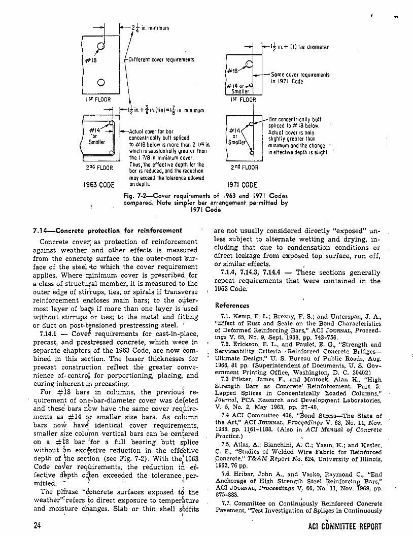
p #lB
o 1ST FLOOR
2nd FLOOR
1963 CODE
D 1 f ferent e o ver reqUiremenls
Actual caver for bar concentncally bull spliced la #18 belaw IS more !han 2 114 in wh1ch 15 substant1ally greater !han !he 1 7/8 m m1nimum cover. Thus, !he effect1ve depth for the bar 1s reduced, and !he reducl1on may exceed the tolerance ollawed on depth.
r'~ m.+ (1) lie dlameter ,....---+--;
#18
#14
2nd FLOOR
1971 CODE
Same cover requ1rements in 1971 Code
Bar concentmally bult spl1ced lo# 18 belaw. Actual cover 1s only shghlly greater !han mm1mum and !he change -in effect1ve depth 1s slight. ·
'
Fig. 7-2-Cover rec¡uirements of 1963 and 1971 Codes comparad. Note sim~ler bar arrangement permitted by
·· 1971 Code
7 .14-Concrete protection for reinforcement
Concrete cover: as protection of reinforcement ,1
against weather and other effects is measured from the concret~ surface to the outer-most ·surface of the steel =to which the cover requirement applies. Where :qainimum cover is prescribed for a class of structural member, it is measured to the outer edge of stifrups, ties, or spirals if transverse reinforcement encloses main bars; to the outermost layer of bafs if more than one layer is ~sed n without stirrups or ties; to the metal end fitting or duct on post-tensioned prestressing steel. '
7.14.1 - Covef requirements for cast-in-place, precast, and prestressed concrete, which wer.e in separate chapters, of the 1963 Code, are now combined in this section. The lesser thicknesses for precast construction reflect the greater convenience of. control for porportioning, placing, and curing in~erent ip precasting. (
For .#)8 bars in columns, the previous requirement of one-bar-diameter cover was de1eted
1 ( '
and these bars n~w have the same cover req,uire-ments as· #14 o'r smaller size bars. As column bars no-ir hav¿ identical cover requirerrients, smaller size coldmn vertical bars can be centered
~ '] rt
on a #1'8 bar for a full bearing butt splice without ~n excªssive reduction in the effective depth of lhe section (see Fig. 7-2). With the~1963 Code coVer requirements, the reduction iri effective d1pth o~en exceeded the tolerance] per-mitted. - · '
The pltrase "¿oncrete surfaces exposed to the weather"=refers to direct exposure to temper&ture and moisture c~anges. Slab or thin shell sbffits
24
are not usually considered directly "exposed" unless subject to alternate wetting and drying, mcluding that due to condensation conditions or direct leakage from exposed top surface, run off, or similar effects.
1
7.1.4, 7.14.3, 7.14.4 - These sections generally repeat requirements that \vere contained in the 1963 Code.
References
7.1. Kemp, E. L.; Brezny, F. S.; and Unterspan, J. A., "Effect of Rust and Scale on the Bond Characteristics of Deformed Reinforcing Bars," ACI JouRNAL, Proceedings V. 65, No. 9, Sept. 1968, pp. 743-756.
7.2. Erickson, E. L., and Paulet, E. G., "Strength and Serviceability Criteria-Reinforced Concrete BridgesUltimate Design," U. S. Bureau of Public Roads, Aug. 1966, 81 pp. (Superintendent
1of Docu,ments, U. S. Gov
ernment Printing Office, Washingto~1 D. C. 20402) 7.3 Pfister, James F., and MattocH:, Alan H., "High
Strength Bars as Concrete' Reinforcement. Part 5: Lapped Splices in Concentl'ically ñ.oaded Columns," Journal, PCA Research and :pevelopwent Laboratories, V. 5, No. 2, May 1963, pp. 27-40.
' 7.4 ACI Comm1ttee 408, "Bond St¡;ess-The State of the Art," ACI JouRNAL, Proceedings V. 63, No. 11, Nov. 1966, pp. 11.61-1188. (Also in' ACI Mnnual of Concrete Practice.)
7.5. Atlas, A.; Bianchini, A'. C.; Yasm, K.; and Kesler, C. E., "Studies of Welded Wire Fabric for Reinforced _Concrete," T&AM Report No. 624, University of Illinois, 1962, 76 pp. .
7.6. Hribar, John A., and Vasko, Raymond C., "End Anchorage of High Strength Steel ~einforcing Bars," ACI JOURNAL, Proceedings V,. f:6, No .. 11, Nov. 1969, pp. 875-883. .
7.7. Committee on Continuously ~inforced Concrete Pavement, "Test Investigati{)~ of Spliqes in Continuously
1,
ACI COMMITTEE REPORT
...
.. Reinforced Concrete Pavement," Bulletin No. 3, Concrete Reinforcmg Steel Institute, Chicago, May 1963, 26 pp.
7.8 Sanders, Ned M., "Splice Length in Reinforced Concrete," Thesis submitted to the Graduate School, University of Colorado, 1963.
7.9. Skillen, Marvin L., "Strength of Lapped Splices in Wide Beams," Thesis submitted to the Graduate School, University of Colorado, 1963.
7.10. Ferguson, Phil M., and Matloob, Farid N., "Effect of Bar Cut-off on Bond and Shear Strength of Reinforced Concrete Beams," ACI JOURNAL, Proceedings. V 30, No. 1, July llltltl, pp, IJ-24.
7.11. Ferguson, Phil M., and Thompson, J. Neils, "Development Length of High Strength Reinforcing Bars in Bond," ACI JouRNAL, Proceedings V. 59, No. 7, July 1962, pp. 887-992.
7.12. Hognestad, Eivind, and Rostasy, Ferdinand S., "Pilot Bond Tests of Large- Reinforcing Bars," ACI JoURNAL, Proceedings V. 57, No. 5, Nov. 1960, pp. 576-579.
7.13 Watstein, David, and 1Mathey, Robert G., "Investigation of Bond in Beam¡ and Pull-Out Specimens with High Yield Strength Deformed Bars," ACI JouaNAL, Proceedings V. 57, No. 9r: Mar. 1961, pp. 1071-1090.
7.14. Bresler, B., and Gilbert¡ P. H., "Tie Requirements for Reinforced Concrete Columns," ACI JOURNAL, Proceedings V. 58, No. 5, Nov. 1~61, pp. 555-570. Also, Discussion, Proceedings V. 58, No. 6, June 1962, Part 2, pp. 897-907.
7.15 Diaz de CossiO, Roger, and Rosenblueth, Em1l, "Reinforced Ccncrete Fallures Dunng Earthquakes," ACI JouRNAL, Proceedings V. 58, No. 5, Nov. 1961, pp. 571-590.
7.16. Concrete Manual, U. S. Bureau of Reclamation, 7th Edition, 1963, 642 pp.
7.17. Hanson, N. W., and Reiffenstuhl, Hans, "Concrete Beams and Columns with Bundled Reinforcement," Tran.sactions, ASCE, V. 125, 1960, pp. 889-904. Also, Development Department Bulletin D25, Portland Cement Association.
7.18. Hadley, Homer· M., Diacusaion of "Concrete l36ams nnd eolumns with Bundled Relntoreement" by N. W. Hanson and Hans Reiffenstuhl, Transactions, ASCE, V. 125, 1960, pp. 905-909.
7.19. Reinforced Concrete-A Manual of Standard Practice, Concrete Reinforcing Steel Institute, Chicago, 15th Edition, 1963, 80 pp.
7.20. "Proceedings of Thirty-Seventh Annual Meeting," Concrete Reinforcing Steel Institute, Chicago, 1961, 77 pp. . 'l 7.21. :danson, Norman W., and Conn~r, Har9ld W., i.'Seismic; Resistance of Reinforced Concrete 3Beam~olumn Joints," Proceedings, ASCE, V. 93, ST5, Oct. 1967, PP-:533-560. ' 7.22. I.Joyd, John P., and Kesler, C. E., "Behavior of One-Way Slabs Reinforced with Deforpted Wire and DeformeP. Wire Fabric," T&AM Re~ No. 32~, Uni;versity of Illinois, 1969, 129 pp.
CHAPTER S-ANAL YSIS AN D DIE S IGN-GIEN IERAIL CON SU DIERATUONS
8.1-Design methods !'
8.1.1 - The general df:!sign prov1s10ns of the Code are referred to as strength design and are similar to the ultimate strength design method contained in the l963 Code. Sorne modifications have been made ·:and a ·J number of additional
~ r· topics are covered to reflect up-to-date knowledge
,\ ·~
gained from research and experience. The strength design method requires service loads to be increased by specified load' factors and computed theoretical strengths to b,e reduced by specified </> factors, given in Chapter 9.
8.1.2 - An alternate method of design employing load factors and </> factors equal to unity is, however, permitted for nbnprestressed members. The method is outlined :rin Section 8.10 and is similar to the working stress design method of previous Codes. ~ For members subfected · to flexure without axial load the method is identical to that given in 7the 19G3 Code. Differences in procedure occur iJ} all otl\Pr cases, including design of columns,¡
1 design for shear, anchorage
length, and splices.1
Although prestrfssed memhers may not be designed · for strength under the provisions of the alternate design ~ethod oi Section 8.10, Chapter 18 permits linear~ stress-slrain assumptions for
BUILDING CODE COMMENTARY
• r "
~.compuVng service load stresses and transfer stresses for use in serviceability control.
8.1.3 .- The general serviceability requirements 1of the Code, such as the requirements for deflectiorl. control and crack control,: must be met 'regardless of whether the general aesign method ';of the Code or the alternate design method of Sectiori 8.10 is used in proportioning for sfrength.
' ' !
~8.2-Required loading
8.2.1 ~- The provisions in the Code are s\ütable for live, wind, and earthquake loads such as those recommended in "Building Code Requi~ements
"for Minimum Design Loads in .Buildiag and ~;Other "Structures," ANSI A-58.1, 'Üf the "'American National Standards Institute (ANSI). If the loads specified by the general building code (of which ¡ACI 318-71 forms a part) differ from those of ANSI, the general building code,governs. However, if the nature of the loads containec:l in the local code differ extremely from A~SI loads, sorne provis~ons of this Code may need mod~jication to reflect the difference. t r
8.2.2 -· This section points out that the jntegral 1
struct'l,lral parts shall be designe~ to r~¡;ist the total ás:sumed lateral load. For example,: a rein-
, ' 1 forced, r~oncrete shear wall is an ;integral struc-
25
tural part. Sorne partitions, because of their method of construction or because of the likelihood of their being moved, are not integral structural parts in the sense of this section.
8.2.3 - This section reads as in previous Codes, but information is accumulating on the magnitudes of these various effects and on procedures for dealing with them. Current8·6
papers in the ACI JouRNAL relate to computation of creep and shrinkage effects.
8.3-Modulus of elastlcity
8.3.1 - Studies by Pauw8·8 indicate that the modulus of elasticity of concrete weighing bet~een 90 and 155 l"b per cu ft can ·be represent~d with acceptable aceuracy by the general formula stated. It is assumed that the aggregates used produce structural concrete. 1
Tests of ~embers made with normal weight aggregates (145 pcf) and lightweight aggregat~s (90 to 115 pcf) 1 having the same cylinder strengths show th~t the differences in moduli cPf elasticity of the :;concrete do not affect the ultimate strength of a member. 3
8.3.2 - The val\le E.= 29 X 106 psi for nonprestressing- steel represents a realistic aver~.ge value obtairted froqt many tests. For prestressing steel, the manufacturer's literature should be consulted toobtain.¡; •.
8.4-Frame~. analys~ and design-Ceneral ~ ~. ti
8.4.1 - Design tload is factored load wh~h means thabthe fac.tored live load such as 1.7L~: is used in Section 8.5.1.2 for adjacent span load~ng and for alternate span loading. When the 1¡11-ternate design method of Section 8.10 is used design loads cont~in load factors of unity for both dead load and live load. In all cases elastic analysis is ~used t~ obtain moments, shears, ~e-actions, etc.· " ~
8.4.2 - ~The s~ggested moment coefficients generally gtve reaspnably conservative values for the stated ~onditio;Ps whether the flexura! members are simply su~ported or are part of a frame. Because the load ~atterns that produce critica! values for momen~ in columns of frames differ from those for maximum negative moments in bearr.s, column tPoments must be evaluated separately. "(See Section 8.5.4.) "
¡, e
8.5-Frame' analysls and design-Details 1 ' ) 1
8.5.1 - .The Code permits the far ends ¡ of columns to :pe assu.med as fixed for the purpose, of analysis unP,er de~d and live loads. The assumption does not apply to wind load analysis. Ho:wever, in analysi&; for wind load or similar lateral loads, simplified methods (such as the portal method) 4:nay be used to obtain the
26
.. moments, shears, and reactions for structures tha t are symmetrical. For unsymmetrical or very tall structures, more rigorous methods should be used.
For gravity load analysis! it can be assumed 'that all columns are fixed at the far ends, and the designer must investigate conditions of pattern loading to obtain the most severe cases. The Appendix of SP-3 (working' stress design handbook) contains a simple method that applies regardless of span lengths. The method is equivalent to a frame analysis by moment distributlon or slope-deflection method with the far ends of all columns fixed.
The two-cycle momen t distribu tion method described in Reference 8.3 also provides a convenient means of determining moments and shears under these provisions. r The foregoing methods of analysis constitute ~ "first order" method since the éffects of deflections and axial deformatlons arr! not included. Therefore, beam and column moments must be amplified for column slenderness i9 accord with Section 10.11. · 1 8.5.2 - The beam moments obtained at the 'center lines of columns may be reduced to those at the face of supports for design purposes. fReference 8.3 provides an acceptable method of laccomplishing this end. ' t r . ~ 8.5.3.1 Although any re~sonablf assumpt10ns p1ay be made with regard to stiffness, more accurate results are obtained in a second order ~analysis (see Commentary ~or Chapter 10) when ,the transformed cracked sections :of beams are ,used rather than the gross sections in computing , momen ts of inertia. 1. The provision in the 196~ Code, which allows t1the torsional stiffness to btr negle,cted in frame ranalysis under certain conpitions ~has been re,moved because of misintE:rpretat~ons, and the hCode is now silent on this, mattet. It has been ;customary to neglect torsiopal stiffness in frame : analysis when torsional stfffness .is small com-' ' ,pared to flexura! stiffness¡ and, e¡xcept for the · provisions of Chapter 13, tqis prac~ice is allowed . by the Code. Because of the approximations used in design, the neglect of this small factor will ~have no important effect on íthe fle>.~ural moments. •1In members subjected toe significant torsional 1stresses, torsional stiffness ~should ·be considered :'in determining torsional moments. :,
· 8.5.3.2 Stiffness coeffiáents 'for haunched 'members can be obtained fr~m References 8.4 and 8.5. : :
.·, 8.5.4 - Columns subjec~ed to ~ignificant bi,'axial bending should be desirned for simultaneous . moments about both rectan;gular a~es. Mimimum
1, eccentricities need be used f?nlY abput one axis at ·a time.
'ACI COMMITTEE REPORT
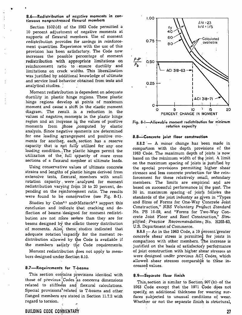
'
8.6-Redistribution of nega2'ive momcnh in con-tinuous nonprestre.ssed fl~xural members
Section 1502 ( d) of the 1963 Code permitted a 10 percent adjustment of negative moments at supports of flexura! members. Use of moment redistribution provides for savings in reinforcement quantities. Experien~e with the use of this provision has been satisfactory. The Code now increases the possible percentage of moment redistribution with appropriate limitations on reinforcement ratio to 1 ensure ductility and limitations on crack widths. This liberalization was justified by additional knowledge of ultimate and service load behavior obtained from tests and analytical studies. "1
Moment redistribution is dependent on adequate ductility in plastic hingt:; regions. These plastic hinge regions de:velop ~t points of maximum moment and causé a shi{t in the elastic moment diagram. The result is a reduction in the values of negative, mome!!lts in the plastic hinge region and an increase il?l the values of positive moments from ~,those )computed by elastic analysis. Since negative f\lOments are determined for one loading o/.range'tllent and positive · moments for anothe~, each~ section has a reserve capacity that is n¡ot fully utilized for any one loading condition., The plastic hinges permit the utilization of the: full qapacity of more cross sections of a flexura! me~ber at ultimate loads.
Using conservative values of ultimate concrete strains and lengths of plastic hinges derived from extensive tests, flexural, members with small rotation capacity. were ~analyzed for moment redistribution varying fn{m 10 to 20 percent, depending on the r~inforc~~ent ratio. The results were found to be cons~rvative (see Fig. 8-1).
' '
Studies by Cohn8·1 and~.Mattock8 2 support this conclusion and in"dicate (~hat cracking and deflection of beams ·1designed for moment redistribu tion are not more severe than they are for beams designed by the elastic theory distribution of moments. Also~ theseC studies indicated that adequate rotation 9capaci~ for the moment redistribution allowed by ~he Code is available if
' ,. the members satisfy tne Code requirements. . ~
Moment redistribution ~oes not apply to members designed und~r SectiQn 8.10.
8.7-Requirements for T-beams
This section corÚains Jrovisions identical with those of previous ~Codes :~s concerns dimensions
~ 'l related to stiffness and flexural calculations. Special provisions1 relate4 to T-beams and other flanged members are stated in Section 11.7.2 with
1 '
regard to torsion. • 1
BUILDING CODE COMMENTARY ,,
0.75
0.25
.R/d =23 b/d: 1/5
o+-----------+-----------4-~~4-~-----~ o 5 10 15 20
PERCENT CHANGE IN MOMENT 1 '
Fig. 8-1-AIIowable moment redistribution for mínimum , rotation capacity '
8.8-· Concrete joist floor construction
8.8.2 ·'- A minor change has been made in compa~ison with the depth provisions of the 1963 Code. The maximum depth of joists . :s now based on the mínimum width of th~ joist. A limit on the maximum spacing of joists is just1ried by the special provisions permitting higher shear stresses and less concrete protection for the reinforcement for these relatively srriall, se~ondary members. The limits are empirlcal al}d are based on successful performance ill' the past. The 30 in. maximum spacing · of joisfs follows the standards of the joist industry as g~ven in -~'Types and Sizes of Forms for One-Way Concrete Joist Construction," NBS Voluntary Pro~uct S~andard No. PS 16-69, and "Forms for Two-Way Concrete Joist Floor and Roof Construction,¡' Simplified: Practice Recommendation¡ No. R265-63, U.S. Dcpartment of Commerce.
8.8.8 - As in the 1963 Code, a 10 is ercent 'greater concreie shear stress is permitte for joists in compafison with other members. he incr.ease is justifi~d on the basis of satisfacto/y perfopnance of joist construction with higher shear stn;sses as were designed und~r previous ACI Codes, which alloweá shear stresses comparablé to tlÍese in-
_; . ' creasea values.
'
8.9-Separate floor finish
This1 section is similar to Sectioni 907 (b) • of the 1963 ~ode except that the 1971 (l::ode dpes not specify¡ an additional thickness for weari!'lg surfaces subjected to unusual conditions o~ wear. Wheth~r or not the separate finis~ is structural,
27
the need for added thickness for unusual wear is left to the discretion of the designer.
As in previous ¡'1editions of the Code a floor finish may only b~ considered for strength purposes if it• 1is cast11 monolithically with the slab, but permi
1
ssion ~~ now given to include a separa te fir~ish in the structural thickness if composite action is ins{¡red in accordance with Chap-
~ ter 17.
All floor finishes may be considered for nonstructural purposes such as cover, fireproofing, etc. Provisions should be made, however, to insure that the finish will not spall off, thus causing decreased cover.
- -8.1 0-Aiternate design method
The design method permitted by Section 8.10 allows the ,use of :Boad factors and <P factors equal to one and!is simii>ar to the working stress design method contained ih the 1963 Code. The procedure for flexure is mue~ the same as 1963 as explained in Section 8.10.1, while for other structural effe;.cts the capaci~y is re~tricted to a percentage of the design capacity given in various Code chapters. In the 1963 Cod~1 the ultimate strength design equations were in many cases divided by safety factors and the resulting equations restated in ~he working stress de~ign sections of that Code. 'the 1971 Code.1 does ~not contain separate sets ¡, of equations Jor wo:r¡king stress design but in ~he Alternate r;>esign Method simply gives percentages for modifying the strength design capacities given in ot\ler par~ of the Code.
In view . of the,- simplifications permitted, the Alterna te Design, Method of Section 8.10 is intended to ~ive re~~.llts slightly more conserva~ive than the designs obtained using the basic design
J l u method ot the Cpde. It allows unity load ~nd capacity r~ductio9 factors for both design ~nd analysis, w.hich m?y result in relative magnitupes for mometl:ts, she~frs, and axial loads which di!fer from those< of the general method. Also, the wqrking stress design provisions of the 1963 Code; al-
" 1 lowed by this method have not been updated as thoroughly, as the basic strength design method
1 ' provisions of the Code.
The Altfrnate ~Design Method does not apply to prestre"ssed c~ncrete design, except for ·~investigation under 1service load in accordance 'fith
• J Sect10n 8.1¡p.1. l.
In general, the resulting flexura! designs will be similar to í those pbtained by working stress design under the \!963 Code. Designs for bear;ing, anchorage ~ length~ (bond), and axial load d~ffer from results obta}ned by the 1963 Code and~the magni tu de,., of dif~rence will depend on the provisions of the Coc{e chapters covering these struc-~~e~~ • .
28
8.10.1 - This section applies only to members · subjected to flexure without axial load. The procedure used is the well-known· straight-line theory with flexura! compr~ssive s~resses in the concrete limited to 0.45fc'. T,~nsile s;tresses in the :steel are limited to 20,000 psi for Grades 40 and 50 steel and to 24,000 psi foi¡' Grade ·~o and higher strength steel. One exception of long standing exists in the case of one-way slabs having clear span lengths 12 ft or less th~t are reinforced with #3 deformed bars or welde~ wire1,fabric having a di ame ter not exceeding . o/s in. , In this case, the allowable tensile stress
1: is the lesser of 0.5f.7
or 30,000 psi. In transforming compression steel to equivalent
"concrete for flexura! design; 2E,/Ec- must be used in locating the neutral axis and calculating moments of inertia. The . lesser of twice the calculated stress in the con)pressidp. steel or the allowable stress is then ~sed to ~:calcula te the contribution of the compression steel in computing the resisting m<;~m~nt at ~service loads. ' This procedure may be used for all sectional shapes with or without compression/einforcement when axial load is not present. Sin¡ce small axial compression loads tend to ·'increas~ the moment capacity of a section, suclf axial ;loads may be disregarded in most cases coi\cerning beams. When doubt exists as to whether !or not the axial compression may be disregarded, the n¡¡.ember should be investigated using Section 8.10.2. J
Deep beams must be designed in accordance . with Section 10.7. 1
8.10.2 - This new pro'cedure for designing members subjected to axiaf load with or without flexure provides more consistent) safety factors than the working stress design method contained in the 1963 Code. Desigrl aids, · based on the 1963 Code, for columns by the working stress de-
, sign method do not satisfy the 1971 Code. -The slenderness effects provid'ed in Section
10.10 apply here, with 2.5P substituted for Pu when dead load plus live load governs. Ir\ Eq. (10-5) for long column considerations,'.</> is taRen as 1.0 when this section is used for desigp. · ,
8.10.4- In computing de;velopmtnt lengths the provisions of Chapter 1r govEtrn. Similarly, splice lengths under Chap~er 7 aue multiples of development length and apply here also. Where Mt and Vu are referenced in Chapter 12, equivalent values are obtained by niultiplying the service load resisting· moment capacity and the service load shear force by 2.0 when gravity loads
\ ' govern. The quantity (d -.a/2) InflY be taken as 0.85d. 1
i 8.10.5 - When lateral Ipads s~ch as wind or
, earthquake combined wit~ live p.nd dead load govern the design, membe~~ may ~e proportioned for 75 percent of capaciti~s requtred in Section
ACI COMMITIEE REPORT
.. 8.10. This is similar to trie provisions of previous Codes which in working. stress design allowed a one-third increase in stresses with these com-binations of loads. · '
1
When approprÚlte, due regard must be given to earth, liquid, or other· loads in earthquake or wind analyses.
8.10.6 - This section' calls attention to the fact that all other provisions of the Code, except those allowing moment redistribution, apply to the alternate method of design. This includes control of deflections and control of cracking, as well as all of the provisions related to slender columns in Chapter 10. Note that the Coromentar~ for Cha);lter 10
0presents an alternative
"Modified R-Factor Method" for slender columns. That procedure may also be used with the alternate method of design ~n lieu of the moment magnification method of S~tion 10.10, if desired.
" '
References
8.1. Cohn, M. Z., "Rotational Compatibility in the Limit Design of Reinforced Concrete Continuous Beams," Flexural Mechanics of Reinforced Concrete, SP-12, American Concrete Institute/ American: Society, of Civil Engineers, Detroit, 1965, pp. 143-180. Also, Development
, . Department Bulletin D101, Portland Ce~ent Association. · 8.2. Mattock, A. H., "Redistribution of Design Bending
Moments in Reinforced Concrete Continuous Beams," 1 Proceedings, Institution of Civil Engin~rs (London), V. 13, 1959, pp. 35-46.
8.3. "Continuity in Concrete Building Frames," Portland Cement Association, Skokie, 4th Edition, 1959, 56 pp. '·
8.4. "Handbook of Frame Constants," Portland Ce-ment Association, Skokie, 32 pp. 1I
< 8.5 "Continuous Concrete Bridges," Portland 'Cement ~ Associa'tion, Skokie, 106 pp.
1
8.6. Finte!, M., "Effects of Column Creep and Shrink, age in Tall Structures-Prediction of Inelastic :Colwnn , Shorte~ng," ACI JouRNAL, Proceedings V. 66,: No. 12, Dec. 1969, pp. 957-967.
' CHAPTIER. 9-STRENGTH AN D SERVDCIEAilU lDTY RIEQU~RIEMENTS
9.1-Ceneral
9.1.1 - The pr~visions 1 ol this chapter correspond closely witp. the :4Indamentals related to ultima te strength -.design of the 1963 Code. Refinements have developed-in certain areas because of subsequent exp~,rience ªnd research.
The Code requiz:€s that the structural strength be adequate to SlWport \he anticipated factored loads and that setjviceabi¡lity of the structure at service load level be assur~d.
As in the 1963 Code, the margin of structural safely is provided in two ways. First, the applied loads are multiplied by ;load factors to provide for excess load effects frcim such possible sources as overloads and simplifi~d assumptions in structural analysis.
A greater factor is ap¡blied to live load than to dead load, since dead load can be determined with reasonable a:ccuracy whereas live load is often more uncert~in and.,subject to change during the life of the structur~. The overall (average) load factor must be large enough to make failures very unlikely, but overall factors must not be unreasonably high. The prescribed factors were devised Wlth this cr"¡terion in mind.
The load facto'rs giv~n are the mínimum recommended by the Con'lmittee. Sorne increase may be appropriate if tlie anticipated loads or the simplifying assumptións are materially different from those ·encountered in the usual design situations. See footndte to Section 8.2 of the Code.
BUILDING CODE COMMENTARY
. '
Second, the theoretical capacity; of thE;. structural element is reduced by a capacity reduction factor cp. The coefficient provides for the possibility that small adverse variations in material strengths, workmanship, and diffi:E!nsions, while ··individ~ally within acceptable tOlerances and limits 0f good practice, may combine to result in
. underclipacity. [ In ~ssigning capacity reductioh factors for
various members, the degree of ductility and the . )
import~mce of the member are consjdered as well as the degree of accuracy with which the strength of the · member can be evaluated. Columns ha ve ~lower tp factors than beams, since the faihí,re of a colum.rf can be sudden and catasttophic ~hile a
'· 1 beam failure normally is precede~ by increased 'deflections and cracking. . Furt~er, a beam may not supp?rt as targe a loaded area as a column. Because~ spirallr reinforced
1 columns are usually more ductil~ than
tied columns, the cp factor for the fo:r;mer is greater than f~r the latter. . . ,
If special circumstances require greater reliance on the; strength of particular members than encounte~ed in usual practice, sorne reduction in the ~rescri~ed capacity reduction factors or igcrease m the¡ prescribed load factors .may be ap-propria:te for those members. ·
With; the development of high; streng~h materials and more sophisticated methods of, design ~~hat pr?vide depths of sections somewhat le~s than those lfSed in the past, it becomes incre9rsingly
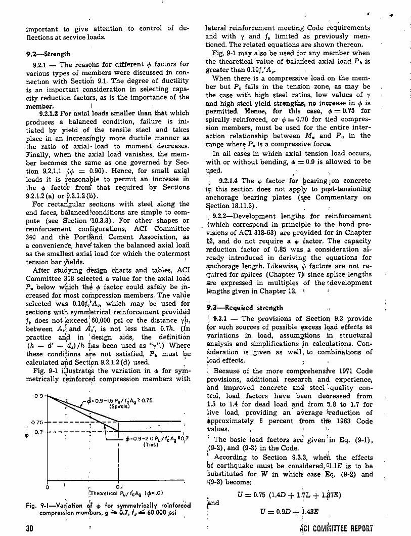
important to give attention to control of deflections at service loads.
9.2-Strength
9.2.1 - The reasohs for different cp factors for various types of m~mbers were discussed in connectwn with Section 9.1. The degree of ductility is an important consideration in selecting capa· city reduction factors, as is the importance of the member. 1
9.2.1.2 For axialloads smaller than that which produces a balanced condition, failure is initiated by yield of the tensile steel and takes place in an increasingly more ductile manner as the ratio of axial- load to moment decreases. Finally, when the axial load vanishes, the member becomes the same as one governed by Section 9.2.1.1 (cp = 0.90). Hence, for small axial loads it is feasonable to permit an increase ih the cp facto~ fromc that required by Sections 9.2.1.2 (a) or p.2.1.2 (b).
For rectan,gular ~ections wi th steel along the end faces, balanced1conditions are simple to compute (see Section ~110.3.3). For other shapes or reinforcement configurations, ACI Committee 340 and the PortJand Cement Association, as a conveniene'e, havé'taken the balanced axial load as the smallest axial load for which the outermost tension bar yields. '
After stuqying d~sign charts and tables, ACI Committee 318 selected a value for the axial lmid Pu below which thé cp factor could safely be illcreased for rhost compression members. The value selected was 0.10f/ A 11, which may be used for sections with symmtetrical reinforcement providéd f
•' 1 • 11 does not ~exceed
160,000 psi or the distance y~,
between Aai and lfa', is not less than 0.7h. (In practice artd in 1 design aids, the definition
1 ' (h - d' - d,) /h :has been used as "y".) Where these condihons ate not satisfied, Pb must be calculated sPd Sectipn 9.2.1.2 (d) used. "•
Fig. 9-1 iiiustrat~ the variation in cp for syrbmetrically ~}inforc~d compression members wÚh
09
075
el> 0.7
qi= 0.9-1.5 Pul f~A11 2: 0.75 (Sp¡rols)
o 1- 0.1
r c~>co.9-2 o Pu/fcA11 2:0"7
(T1es) -'
rheore!lcol Pu/f~Ag (c/>•1.0)
Fig. 9-1-Va;·iation ¿'f cp for symmetrically reinforc'éd compress1on mem'bers, g::::::... 0.7, fu L. 60,000 psi
' l
3D
••
lateral reinforcement meeting Code requirements and with y and fu limited as previously mentioned. The related equations are shown thereon.
Fig. 9-1 may also be used for any member when the theoretical value of balanced axial load Pb is greater than 0.10fc' A 11•
When there is a compressive load on the member but Pb falls in the tension zone, as may be the case with high steel ratios, low values of y and high steel yield strengths, no increase in cp is permttted, Menee, for this case, 4> = 0.75 for spirally ·reinforced, or, cp = 0.70 for tied compression members, must be used for the entire interaction relationship between Mu and Pu in the range wher~ P u is a compressive force.
In all cases in which axial tension load occurs, with or without bending, cp = 0.9 is allowed to be used. \3 - .. ,
1 9.2.1.4 The cp factor for \jlearing ¡on concrete i~ this section does not apply to pqst-tensioning anchorage bearing plates (~e Colrlmentary on ~ection 18.11.3).
: 9.2.2-Development lengths for reinforcement . (which correspond in principie to the bond pro
visions of ACI 318-63) are pro.vided for in Chapter 112, and do not require a cp factor. The capacity ll!duction factor of 0.85 was, a consideration already introduced in deriving the equations for l:PlChorage length. Likewise, <p factoJ.i.s are not required for splices (Chapter 7) since splice lengths are expressed in multiples of the cdevelopment l~ngths given in Chapter 12. '
9.3-Required strength '1
~ 9.3.1 - The provisions of Section 9.3 provide ~or such sources of possible Epecess lqad effects as yariations in load, assumgtions in structural analysis and simplifications in calculations. Con~ideration is given as weu': to co~binations of load effects.
~ Because of the more comprehensive 1971 Code provisions, additional reseatch and experience, and improved concrete and steel ~ quality control, load factors have been deereased from 1.5 to 1.4 for dead load ~d from ~.8 to 1.7 for live load, providing an' average i:reduction of ~pproximately 6 percent ftom tlfe 1963 Code val u es.
' The basic load factors are given ~in Eq. (9-1), .(9-2), and (9-3) in the Code. " According to Section 9.3.3, whe~ the effects bf earthquake must be considerad, 111.1E is to be substituted for W in whiclt case Eq. (9-2) and 1(9-3) become: ·
and U= 0.75 (1.4D + 1.7L + Ül7E)
1 '
1 U = 0.9D + ~.43E
• J
ACI COMMITTEE REPDRT 1
When lateral loads (H) due to earth (or other granular) pressure are present, the governing equations become:
1
U= L4D + 1:7L +L7H
U= 0.9D .;¡._ 1.7H and !)
U= 1.4D + 1.7L
When lateral loads F due' to liquids are present, •1
the governing equations are:
and
U= 1.4D + 1.7L + 1.4F
U = 0.9D + 1.4F
U = 1.4D + 1.7L
It should be noted that in applying Eq. (9-1), (9-2), (9-3) and other load factor provisions of Sect10n 9.3, due regard sh'ould be paid to sign, since the standard effects bf D, L, W, E, H, and F m ay, on occasion, be of opposing sense, thus producing tensile axial loa:ds, negative reactions, or reverse bending. '
The designer shotÜd condider the effect of differential settlement, creep, * shrinkage, and tem-
- 1
perature where necessary. Denoting the worst ef-fects of axial force~: shear,~ moment, and torsion due to the combination of these conditions as X, it is then necessar,.y to investigate the design using the equation: '' '
U= 0.75 {f.4D + Í.7L + 1.4X)
When impact is present,' as may be the case for parking bu1ldings, load_mg docks, warehouse floors, elevator shafts, etc., impact effects should be considered and Ífnpact joads, if any, included with live loads in the vanous equations for required strength.
9.4-0esign strengths for reinforcement
An upper Iimit ofl 80,000=ipsi is placed on reinforcing yield strength (other than prestressing tendons) in Section~9.4.2. aommittee 318 did not choose to recommeild any :strength above 80,000 psi without addmg ~ other testrictions since this steel strength is aboqt equa~ to the ultima te strain in concrete multiphed by the modulus of elasticity of steel. At present the [highest yield strength covered by ASTM l standards is 75,000 psi, and this grade is not w1dely used.
9.5-Control of deflections 1
9.5.1 General - This section is concerned only e l w1th the deflections or deformations which may occur at service load levels. Where long-time deflections are compüted, only the dead load and that portian of the 1 Iive loh.d which is sustained need be considered. ~
~ l BUILDING CODE COMMENTARY::
Two methods are given for controlling deflections. For nonprestressed beams and one-way slabs, and for composite members, .· provis~on of a mínimum overall thickness as required by Table 9~5 (a) will satisfy the requirements of the Code for members not supporting o.r attached to partitions or other construction likely to be damaged by large deflections. For nonprestressed two-way construction, mínimum thicknesses as requ1red by Sections 9.5.3.1, 9.5.3.2, a~d 9.5.3 . .3 will satisfy the requirements of the Code. 1
For nonprestressed members which do not meet these mínimum thickness requirements or which support or are attached to partitions or other con~.tructio:t;¡. likely to be damaged Qy larg~ deflections, and for all prestressed concrete flexural members, deflections must be calculated by the procedures described or referred t? in the appropriat_e sections of the Code and áre limi~ed to the valu'es in Table 9.5 (b). ' ; K 1
~ 9.5.2 IYonprestressed one-way constructio~
1 9.5.2~2 The calcula tion of imm~dia te <!eflec~ions fo~ uncracked prismatic beams, is relapvely sjmple; the usual methods or formulas for ~lastic geflecti~ns may be used with a con~tant va¡ue of fcl 0 alopg the length of the beam .. Howeyer, if the be a~ is cracked a t one or mor1e secti~ns or ij its depth varies along the span, exact calculation becomes. much more complicated. The Ie
) . wocedure described in this Code, sectio~ and qevelopE¡d in Rderence 9.8 was selected as
1being
~elatively simple and sufficiently )accura\e for use witn the limiting values in Table 9.5 (b) to ¿on trol deflections. 0 1 • 0 ·0• D 0 ·
' ' '
J It is noted that for additional load increi(Ilents, such as, live load, le must be computed for the total mdment, and the deflection increment computed f~om the total deflection, as indicatfd by Eq. (29), to (32) in References 9.9 ~d 9.1~. For s!mplicity in the case of continuou_l> beams, the Code ptocedure suggests a simple ¡'averagi~g of ijositiveJ and negatlve moment val~es for iio. In ~ertain Fases, a weighted average relative ~o the ~omen~ may be preferable, such as, the m~thods spggest~d in Reference 9.10. , , ) For normal weight concrete, the ~.alue oflf, req~uired f~r the calculation of the cracking m~ment i~ given as 7.5 Vf/. Modifying factors: based qn the splitting,tensile strength fct are given for "all~lightweight" i and "sand-Iightweight" conbretes. For a 11ghtweight aggregate from a given sourre, it· is intended that appropriate values of fct shoulld be obtained in advance of design, bub tests for fct are notJ required for subsequent acceptance of concrete; during construction. Indirect contr~ will ~
·1· t 't e •For Crcep constdcrations, see Symposium <- n Crecp o on-cfcte, SP-9, Amcrtcan Concrete Instltute, Det"'it, 1964, •160 pp. See also Reíerence 9.9.
' 31
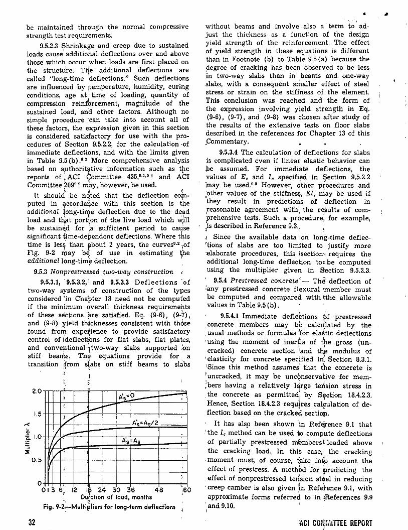
be maintained through the normal compressive strength test requirements.
9.5.2.3 $hrinkage and creep due to sustained loads cause' additional deflections over and above those which occur when loads are first placed on the structu:re. THe additional deflections are
1
called "long-time deflections." Such deflections are influenced by ¡temperature, humidity, curing conditions, age at time of loading, quantity of compression reinfbrcement, magnitude of the sustained load, and other factors. Although no simple procedure :can take into account all of these factors, the expression given in this section is considered satisfactory for use with the procedures of Section 9.5.2.2, for the calculation ·OÍ
immediate deflections, and with the limits given in Table 9.5 (b) .0 ·2 More comprehensive analysis based on é)uthoritr_tive information such as tpe reports of tACI ~ommittee 435,0· 1•0 4 and ACI Committee t09° 0 may, however, be used.
~ " E Tt should be nqted that the deflection COl(l-
puted in accorda~ce with this section is the additional iong-time deflection due to the dead
l LO 11
load and thrat port\on of the live load which ~ill be sustain~d for f sufficient period to cause significant time-dependent deflections. Where this ti~e is lesi than rbout 2 years, the curves0·2 ;of F1g. 9-2 rpay be of use in estimating ~he additionallong-tim~ deflection.
1
9.5.3 N onprestressed two-way construction
9.5.3.1, · 9.5.3.2, J and 9.5.3.3 Deflections · of two-way systems of construction of the types considered 1in Chapter 13 need not be computed if the mínimum overall thickness requiremehts of these se'ctions ~re satisfied. Eq. (9-6), (9-7), and (9-8) yield thicknesses consistent with thÓse found fro~ expe~ience to provide satisfactory control of ldeflect~ns for flat slabs, flat plates,
¡ ' and conve~tional1two-way slabs supported Jon stiff bearns. The equations provide for a transition Úom slabs on stiff beams to sÚ!bs
'(L)
2.0
1.5
0.. 1.0 -:l ::!!:
0.5
o
32
/~ r-; i
" (
: r
e
y
·--.,..
1
'·
.,..
-
1 r ~
t :.,........--.......
--
1
A.' :::0 s...--~ 1
' 1
A's=As/2
1
As=As --
013 6,, 12 1~ 24 30 36 48 Duratton of load, months
·-. ti Fig. 9-2~MultiP,Iiers for long-term deflections
,,
'
., e :60 1
- ·, •'1
without beams and involve also a· term to adjust the thickness as a function of the design yield strength of the reinforcement. The effect of yield strength in these equations is different .than in Footnote (b) to Table 9.5 (a) because the degree of cracking has been observed to be less in two-way slabs than in beams and one-way slabs, with a consequent smaller effect of steel stress or strain on the stiffness of the element. This conclusion was reached and the form of the expression involving yield strength in Eq. (9-6), (9-7), and (9-8) was chosen after study of the results of the extensive tests on floor slabs described in the references for Chapter 13 of this "Commentary. ~
9.5.3.4 The calculation of deflections for slabs is complicated even if linear elastic behavior can .):>e assumed. For immediate deflections, the values of Ec and Ic speciíif!d in ~ection 9.5.2.2 'may be used.0·0 However, 9ther p:rocedures and ;other values of the stiffnes~, EI, m,ay be used if they resul t in predictions of deflection in reasonable agreement with
1
the results of com-1 1 1
prehensive tests. Such a procedure, for example, )s described in Reference 9.3. . (
1 Since the available data ·~on long-time deflec'tions of slabs are too limited to justify more ~elaborate procedures, this isectiom requires the additional long-time deflection to::: be computed using the multiplier given in Section 9.5.2.3.
1 9.5.4 Prestressed concrete'c- Th~ deflection of ·~any prestressed concrete flexura! ·member must be computed and compared with tthe allowable values in Table 9.5 (b).
9.5.4.1 Immediate deflehions bf prestressed 4 ' . concrete members may be calc\i1la ted by the
. usual methods or formulas )for ela~tic deflections 1 using the moment of inerÚa of the gross (un-
' 1 cracked) concrete section 1and th~ modulus of 1 elasticity for concrete specified in:' Section 8.3.1. 1 Since this method assumes· that the concrete is funcracked, it may be unc6nservative for mem;bers having a relatively l¿rge terlsion stress in ; the concrete as permittedt by S~rction 18.4.2.3. Hence, Section 18.4.2.3 requlres calfulation of deflection based on the cracke~ sectiO§l.
1t has als9 been shown 'in Ref~ence 9.1 that .~ the Ic method can be used tp compute deflections of partially prestressed members t loaded above the cracking load.. In this case,· the cracking
· moment must, of course, t(ake in" account the effect of prestress. A methbd for predicting the
. effect of nonprestressed te~sion st~el in reducing 1 creep camber is also given ~n Refetence 9.1, with approximate forms referred to in ~References 9.9
1 '
and 9.10. 1
9.5.4.2 The calculation of long-time deflection of prestressed concrete flexura! members is complicated. Any suitable method, such as that described in References 9.4, 9.9, and 9.12 may be used.
9.5.5 Composite members - Since few tests have been made to study the immediate and longtime deflections of composite members, the rules given in Sections 9.5.5.1 and 9.5.5.2 are based on tho judgment of tho committea and on
• ' 11 exper1ence. 1
If any portion of a ,composite member -is prestressed or if the member is prestressed after the components have been cast, the provisions of Section" 9.5.4 apply and deflections shall always be calculated. For nonprestressed members, deflections need be calculated and compared with t~e limiting values in Table 9.5 (b) only when the thi~kness of the member or the precast part1 of th~ member is less than the minimum thickness gi~en in Table 9.5 (a). In unshored construction the thickness of concern depends on whether the, deflection befare or after the attainment of eff~ctive composite action is being considered. •
~ 1
Table 9.5(a) This, table,E based on the use of reinforcement having yiel~ strengths of 60,000 psi, is referred to only in Sections 9.5.2 and 9.5.5. It may be used in lieu of calculation of deflections only for the; types of members covered by those se~tions apd only if these members do not support and 6 are not attached to partitions or othez;. const¡;uction likely to be damaged by large d~flection~.
The notes beneath the table are essential to its use for reinforced concrete members constructed with structural ; lightweight concrete and/or wi th reinforcerqen t having a yield strength not equal to 60,000 psi. If both of these conditions exist, the corrections in Footnotes (a) and (b) shall both be made.~
The modification 11
for lightweight concrete in Footnote (a) is based on :studies of the results and discussions in Referen-ce 9.5. No correction is given for concretes weighing between 120 and 145 lb per cu ft since the c"orrection term would be clase to unity in t};¡.is rang,e.
The modification f'or yield strength in Footnote (b) is based on judginent, experiemce, and studies of the results of ~tests rand of unpublished anal~ses. The simp'le expression given is approxlmate but shoul,d yield¡ conservative results for the types of membern considered in the table, for typical reinforcement ratios, and for values of fv between'l40 ancf 80 ksi.
If t~e mi~imum t~icknesr obtained using this table 1s cons1dered e?cessive! the designer has the
BUILDING CODE COMMENTARY ¡,
1 1
option of computing deflections m accordance wiLh Sections 9.5.1 and 9.5.5.
Table 9.5 (b) This table is the result of an effort by Committee 318 to simplify the very extensive set of limitations which would be required to cover all possible types of construction and conditions of loading. (See, for example, Reference 9.6.) It should be noted that for members supporting or attached to other elements, the limitntions gtvan in this table relate only to supported or attached nonstructural elements. For those structures in which structural me'ffibers are likely to be affected by deflection or deformation of members to which they are attached in such· a manner as to affect adversely the strength of the structure, these deflections and the resulting forces should be considered explicitly ip the analysis and design of the ~tructu!fes as z:equireq, by Section 9.5.1.
Wheré long-time deflections are computed, the portian 'of the deflection befare attachment Óf the rlonstructural elements may be deducted. Inrmakihg this correction use may be :rhade of the éurves in Fig. 9-2 for members of usual 1 sizes and shapes. l
1 !
References 1 ', 1
, 9.1. ACI Comm1ttee 435, "Deflections of Remforced , ' r , Concrete Flexural Members," ACI JouRN~L, Procé'edings V. 63, No. 6, June 1966, pp. 637-674. Also ACI Manual of Concrete Practice, Part 2, 1968. ~ 9.2. Yu; W. W., and Winter, G., "lnstantaneous and
I!.ong-Time Deflections of ReinfOTced Concrete j3eams under Warking Loads," ACI JOURNAL, ProceedingS¡ V. 57, No. 1, Jufy 1960, pp. 29-50. 1 · , 9.3. Va!Jderbilt, M. D.; Sozen, M. A.; and Siess,. C. P.
"Peflectiqns of Multiple-Panel Reinfo~ced Concret~ Floor Sla)Js," Proceedings, ASCE, V. 91, ST4, Aug. 1965, pp. 77-lOi. e e
~ 9.4. Subcommittee 5, ACI .Committee 431
5, "Defl~ctions ol Prestressed Concrete Members," ACI \rouRNAL Proceedings ;V. 60, No. 12, Dec. 1963, pp. W97-172iií Also A,CI Man~l of Concrete Practice, PaTt ~~ 1968. L
~ 9.5. ACI Committee 213, "Guide for Structural Í..ightweight Aggregate Concrete," ACI JOURNAl, Proceedings V .. 64, No, 8, Aug. 1967, pp. 433-464. Also, ·Discussion by R'alph N.' McManus and Committee, Closure; ACI J9URNAL, :Froceedings V. 65, No. 2, Feb.
11968, pp~ 151-
155. Also ACI Manual of Concrete Practice, PaTt 1. 1970. ¡ ' :19.6. ~u~committee 1, ACI Committee 435, "All~'wable
Deflectwm;,'' ACI JOUR1JAL, Proceedings V. 65, No. 6, June 1968¡ pp. 433-444.
~9.7. Lin,1 T. Y., "Load Factors in Ultirriate Design of ~einforcea Concrete," ACI JouRNAL, Prot:·eedings ·v. 48, No. 10, JJne 1952, pp. 881-900.
9 r , J .8. Brarson, ~an E., "!nstantaneous épld Tmw-De-
pendent Úeflectwns on Simple and Continuous .Reinfqrced Capcrete Beams," HPR Report Ño. 7, Part 1, Alabama Highway Department, Bureau of Public Roads Aug. 1963 ~(1965), pp. 1-78. · - '
.¡ e ' : ~ ' ~In Chapter 17, it 1s stated that distinction m;~d not be made
betweP" ~hdred and U"shored members. This refers to strength cakula.tions, not to deflections.
) 1
9.9. Subcommittee 2, ACI Committee 209, "Prediction of Creep, S~rinkage, and Temperature Effects in Concrete Structures," Designing for the Effects of Creep, Shrinkage, and Temperature in Concrete Structures, SP-27, American Concrete Institute, Detroit, 1971.
9.10. Bran~on, D. E., Discussion of "Proposed Revision of ACI 318-63: Building Code Requirements for Reinforced Concrete" by
1 ACI Committee 318, ACI JoURNAL,
Proceedings V. b7, No. 9, Sept. 1970, pp. 692-695. 'i
9.H. Shaikh, A. F., and Branson, D. E., "Non-Tensioned Steel m Prestressed Concrete Beams," Journal, Prestressed Concrete Instltute, V. 15, No. 1, Feb. 1970, pp. 14-36.
9.12. Branson, D. E.; Meyers, B. L.; and Kripanarayanan, K. M., "Time-Dependent Deformation of Noncomposite and Composite Prestressed ·Concrete Structures," Symposium on Concrete Def.or~ation, Highway Research Record 324, Highway Research Board, 1970, pp. 15-43. '
¡· 11
CIHAPTER 10-iFliEXUR.IE AND AXBAl LOADS " '¡ ,,
1 O. 1-Scope and ~ 1 0.2-Assumptions
While Chapter ~ 10 follows the broad lineS, of ACI 318-63, numerous minor changes have been made. Detaile~1 formulas for determination of ulti:q1ate
loads and ffnOmen~ have been eliminated in v,iew of their general awailability in reference texts ,and design aids. ~
10.2.3 .....!. The maximum concrete compressive strain at ültimat~ strength has been measuretl in many tests of both plain and reinforced conérete members. 'Though the maximum strain decreases · somewhat with increasing compressive strength of the concrete, a value of 0.003 is reasonably conservative.
10.2.4 -This section assumes that below the design yiel? strength of the reinforcement, steel stress is proportional to strain, and that the effect of strain hardening of the steel beyond the yield point is néglectecf.
10.2.6 - This clause recognizes the inelastic behavior oft,concrete at high stress, that is, that the stress-strain rel4tionship for concrete is rlot a straight rine bu~ sorne forro of curve. The actual distributibn of concrete compressive stress in any particular case is' complex and usually not known. However~ researi:h has shown that the important properties of th~ concrete stress distribution can be approximated closely using any one of several different assum~tions as to the forro of stress distribution .. This clause permits any particular stress distribution to be assumed in design if shown to result in_ predic~ions of ultima te strength ill reas~nable ~greemépt with the results of compr~hensive tests,;
10.2.7 +- The, equivalent rectangular cot;.crete stress di§tributipn specified in this clause is an expedien_t whic{l enables the designer to qbtain in a simple manner the total concrete compressive
' L ' force ancJ its ceq.troid. It does not purport t~ rep-resent t~ actua:l distribution of stress in the concrete compressi§>n zone, but provides essentially the same results as those obtained in compi'ehensive tests.
34
1 0.3-General principies and requirements
Using the equivalent rect_angular_ concrete stress distribution together with the other assumptions specified in this Code, equations for the design of members subject to flexure or combined flexure
1 • and axial load are derivefl in t~ paper, "Rec-tangular Concrete Stress Distribution in Ultimate Strength Design."10·18 This paper also gives the derivations of strength equations for cross sections other than rectangular. r
It is required that the ratio of the tension reinforcement in a flexural mefnber n~t exceed 75 percent of the ratio of tension reinforcement which corresponds to balanced conditions, that is, to the simultaneous occurrence qf yield of the tension reinforcement and crushing of the cqncrete at ultimate strength. In other words, A,f11 of the tension steel is limited to thr~e-qualjters of the total compressive force at balanced conditions, whether that compressive force is froni a rectangular stress block of a rectangular merrlber, or that plus overhanging flanges, or 1that plus compressive steel. This requiremen~ applies to 1members of any cross-sectional shape with !or witllout compression reinforcemen t. 1 ~
The wording of Sectioh 10.3.2 is intended to assure an interpr~atlon b.E the fequirements for flanged membets -a.nil -m~'ií'bers 'fith compressive reinforcemen t, w hich is dmsistent wi th tha t used for rectangular members ~ wi th ténsion reinforcement only. In the past, a1less cobservative ínter-
¡ • pretation has been used for flanged members and members with compressiv"k reinfd¡cement.
The limitation on tensile reinforcement insures that flexura! members d.esigned'. by the strength procedures will have a dbctile dharacter. Among other reasons, this is desi'rable b~cause long-term experiences with reinfor~ed concrete in the field pertain to relatively du¿tile str~ctures. Further-
. more, there has been implicit rehance on the ductile behavior of structurJs to ae¡commodate those factors which are not normally ~onsidered in design calculations, such as the djfferential settle-ment of foundations. ,
Ductile behavior must continue to be insured and, therefore, a limit 01i the nát amount of ten-
( '
ACI ~OMMITTEE REPORT
!•

' s1on reinforcement provided in flexura! members has been set at 0.75pb. This limit is further reduced to 0.5pb where negative moments are redistributed in design (see Section 8.6). These numericallimits remain the same as in the tp63 Code.
10.3.2, 10.3.3, and 10.3.4':--..: The reinforcement ratio pb which produces bal1anced conditions under flexure, depends on' the sh'ape of the cross section and the location of the reinforcement.
Derivations for p!J\ in a rectangular member with tension reinforcement only, in a rectangular member with tension and comprcssion reinforcement and in a flanged beam are given in Fig. 10-1a,
(o)
For a rectangular beam
Ec=0003 ¡• ¡..---;-----
( b) (el
=d( o 003 ) = d ~ o 003 ) =d ( 87,000 ) e f y 1 1 f vy 8 7 000 + fy o 003 +- "0003 +-4-<---- '
Es ) 2~ X 106
T=Pbbdfy =e= b$1c085fc' •085fc'b.91d 87.~6~0~ 1 Y Where e = compressove force
T = tensole force
Solvong
.91o 85fc' 87,ooq
Pb= fy 87,000·1'"(y
Fig. 10-1 a-Expressiori for pb; rectangular be a m without compression reinforcement
Q As2 T. •C 111 -2b 2b
(Tb•pbb~ly) •(T1 b=~'llbdfy) + !T2 b•p'bdf~) Pb = ¡;b +1p' 1~ "r
~or oecoonQulor be o m 1 F1g IQ.- 1 o)
e =d( '87,000 ~ or l/c :.!..¡ 87,000tfy) 87,000tly d 87,000
From stra1n tnongle
Wnere
f~ • E5 •~· E 5 [(c~ d'l0003] • 87,000 (l·d'tc)
•87000(1- i 87,00.0tly -' d 87,000 le fy
1 •
= 87,000 [ 1- ~ 1 1 + 'r t'87,000l)
Pb • bolonced remforc~ment rot1o lo; o rectangular beom ol wodth wothout compressod'n reonlorccm~nt
1
Fig. 10-1 ¡;_Expression1 for pb,.' rectangular beam with compression reiníorcement
,., ~'
BUILDING CODE COMMENTARY
(¡/
10-1b, ~nd 10-1c. Balanced reinfor~ement ·1:ratios for these members are summarized in Table 10-1.
1 '• Similar approaches can be made for': other shapes symmetrical about the vertical axis. ¡With s~htions unsymmetrical about a vertical axi~, the neutral axis will be inclined and twist will develop unless the member is laterally braced again~t rotati~ns.
10.3.6- Mínimum eccentricities aie provided to account for accidental eccentricities aue to ilnperfect posi tioning of members and r~inforc~men t, nonuniformity of materials, and ':linor discrepancies between assumptions made in the arialysis and actual behavior. 1
1
The mínimum eccentricities of 0.05h for spirally reinforc_ed members and 0.10h for iied members ~ 1
Where
C_w 'JTw=Aswfy
Pb Tw= bwd fy
Tw =pbbwdfy
Cw• bwl'lJC 0851~
Ct • Tt: Asf fy
r, = Ptbwdty
pbbdly =pbbwdfy + p 1bwdfy
- b w -Pb --b-(Pb+Ptl
subscrt'pt w relers to web woth w•dth bw• subscropl f trefers to flonge woth wodlh b- bw
Pb = bolanced reonforcement rotto foro rectangular beom al wtdth bw wolhout compressoon reonforcement
A-sr PI • li;d reonforcement rotoo for tensoon soeel, A5r, to c!J!velop lhe
' compressove strength of the flonges ( b -bwl ~~ Q_ 0851(: (b-bwl hf ~
Ast • fy = fy ol
Fig. 10-1 c-Expression for pb, T-~eam l
1
' ' TABLE 10-1-BALANCED REINFORCEMÉNT RATIO Pb 1 1 1
For rectangular. beams with tension steel only
- 0.85 ~lfc' 87,0001, 1, Pb = Pb = fy -=8=-=7,...,,0:-::o-'-=o-+-rf,...!l
For rectangular beams with compress10n steel
where
_- , fs' Pb- Pb + p --¡;;
· fs' = stfess in compress10n steel
fs' = 87-,ooo ( 1 - .E:_ 87,ooo + fy )' ~fU . • d 87,000 ' " ' . '.
For T-Beams wlthout compressioft steel ~
bw -Pb = -b- (pb + p¡)
Where p1 is the reinforcement ratio fo~ tensio~ steel area necessary to develop the compressive strength of oyerhang!ng flanges (see Fig. 10-lc). ! ~
35
are the same as in the 1963 Code, the 1956 Code, and the January 1956 report of the ACI-ASCE Committee 427 (327), Ultimate Load Design. The Q.05h has also been specified for steel encased compression members because of the similarity to spirally reinforced members.
Elimination of the mínimum column size provisions of the 1963 Code, Section 912 (a), as well as consideration óf dimensional tolerances made it advisable to es~ablish a 1 in. mínimum eccentricity for compression members in addition to the :previously menti9ned 0.05h or 0.10h minimums for spirally reinforced and tied columns, respectively. It was intended that such eccentricity should be applied about each of the principal axes of the column cross section, but not about both simultaneously.
Corner and other columns exposed to known moments ábout e~ch axis simultaneously shopld be designtfd for Q.iaxial bending, taking into 'account the.,l mínimum eccentricity where apJ.lic-able.lO.t.lo .•. 1o.la,lo.n J
1 ¡
l ' 1 0.4-Dis~ance between lateral supports of flexural members 1 t 1
,l Tests ha¡ve shown that laterally unbraced rein
forced conj::rete b:eams of any reasonable dimensions, eve~ when~they are very deep and narrbw, will not fail prematurely by lateral buckling¡lo.lo This holds¡ true p~ovided the load is well centered in regard to the v~rtical midplane of the beam. -For this reason it wa:; found possible to increase ¡the maximum ~distanóe between lateral supports from the value t32b, p~scribed in previous editions of the Code, ,J:o 50b iP the 1963 Code. This value. has been retaip.ed in tpe 1971 Code. ,1
Laterally unbra,ced beams are frequently loaded slightly o~f centen: (the "lateral eccentricity" rhentioned in ''the C6de) or with slight inclination. Stresses a~d defdrmations set up by such loading imperfections become detrimental for narnow ,, ' deep bea~s, the ~ore so as the unsupported length increases. Laterai supports closer together than 50b may b'e requi~ed by actualloading conditiÓhs.
1 ~ 'l
1 0.5-Minimum 'reinforcement of flexural members' ()
\ ~
Section. 10.5.1 ~s concerned with beams, which for architectural pr other reasons, are much larger in cross s~ction *an required by strength considerations. With ~ry small reinforcement ratios, the comp~ted b~nding moment as a reinforced concrete section !becomes less than that of
1 the
corresponsling plain concrete section computed from its ~odulu~ of rupture. Failure in sueh a case is quite sudd~n. t
To prevent such failure, there is requiréd ·a minimum1steel ratio, p = 200//11, which, for 4('),000
3S
and 60,000 psi yield point steels, becomes 0.5 percent and 0.33 percent, respectively.
The 200/fu value was derived by equating the strength computed by the modulus of rupture of the plain concrete section to the strength computed as a reinforced section and solving for p. This mínimum reinforcement must be provided , wherever positive reinforcement is needed, except ,where the reinforcement is one-third greater than : required by analysis. This exception provides suf-ficient extra reinforcement for safety in large members where 200bdffv would be excessive.
In Section 10.5.2, the mínimum reinforcemen t required for slabs is a little less than that required for beams, since an overload would be distributed
· laterally anda sudden failure woulcí be less likely. The structural reinforcement should, however, be at least equal to the shrinkage and temperature reinforcement. ·
1 0.6-Distribution of flexúral reinforcement in beams and one-way slabs '
1 l
This is a new provision requiring distribution of reinforcement in zones of !:oncret~ tension. Severa! bars at moderate spacip.g are puch more effective in controlling crac~ing than one or two larger bars of equivalent ar~a. .
In Section 10.6.2, a form~la is gi~ren which will provide a distribution that will r,easonably con-trol flexura! cracking. e -
Many structures design~d by f"Orking stress methods and with low steel stress served their intended functions with 'yery li¡nüted flexural cracking. When high streljlgth retnforcing stcels are used at high service Jpad strfsses, however, visible cracks must be expected, and steps must be taken in detailing of thé reinfotcement to control cracking. To assure Rrotectiqp of reinforcement against corrosion, and for aesthetic reasons, many fine hair cracks are preferable toa few wide cracks.
Only deformed reinforc~ment ts permitted as main reinforcement in the 1971 .tode. The best crack control is obtained Jhen thli steel reinforcement is well distributed &ver the zone of maximum concrete tension. It \s prudemt to use rclatively small bar sizes. In tnajor T-beams, part of the negative reinforcement should be placed in the flanges near the web;~ othervJise only a few
'd ~ S ' w1 e crack's may extend iñto the slab even when f . k , ¡]
numerous me crac _s ex~st~dire~tl~ over the web. Control of crackmg 1s 1 partlcu~arly important
when reinforcement with ~a yield!strength in excess ~f 40,000 psi is used. :currenf good detailing practlces will usually lead; to ade~uate crack control even when reinforcerhent of~1 60,000 psi yield is used. With careful att~ntion fO steel details, entirely satisfactory struc~tures nave been built, particularly in Europe, wit,h desig' yield strengths
( '
'l ACI COMMITTEE REPORT
..
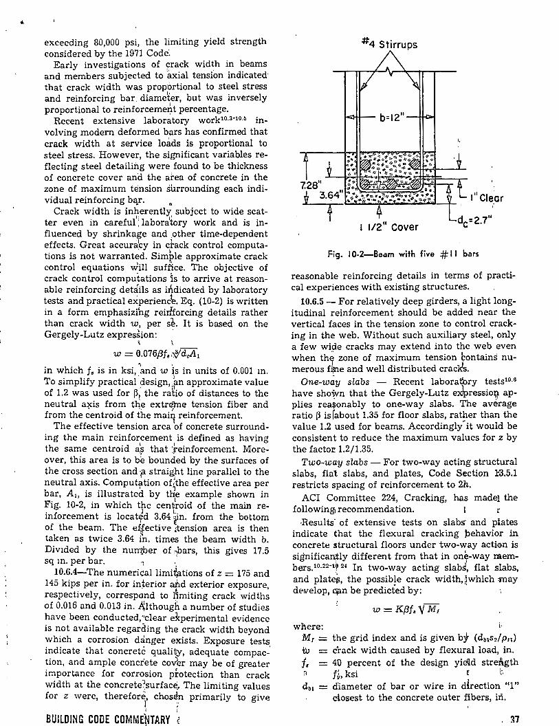
exceeding 80,000 psi, the limiting yield strength considered by the 1971 Code~
Early investigations of Fack wid~h in beams and members subjected to 'axial tension indicated' that crack width was prop'ortional to steel stress and reinforcing bar. diame~er, but was inversely proportional to reinforcemeAt percentage.
Recent extensive laboratory work10·3-10·5 involving modern deformed bars has confirmed that crack width at service loads is proportional to steel stress. However, the significant variables reflecting steel detailing were found to be thickness of concrete cover and the a:rea of concrete in the zone of maximum tension surrounding each indi-vidual reinforcing b~r. •
Crack width is inherently subject to wide scat-lr 11
ter even in careful: laboratory work and is in-fluenced by shrinkage and · .other time-dependen t effects. Great accura:cy in ~tack control computations is not warranted. Simple approximate crack control equations will suffice. The objective of crack control computations is to arrive at reasonable reinforcing detcfils as iÓ.dicated by laboratory tests and practica! e~perienc~. Eq. (10-2) is written in a form emphasizihg rein'forcing details rather than crack width w, per s~. It is based on the Gergely-Lutz expression: ·
\
w = 0.076{3f8·~dcA.l in which f. is in ksi, -and w is in units of 0.001 m. To simplify practical.design,:
1an approximate value
·' '1 of 1.2 was used for ~~ the ratio of distances to the neutral axis from the extréhle tension fiber and • -, r
from the centroid of the mai~ reinforcement. The effective tension area of concrete surround
ing the main reinforcement is defined as having the same centroid a's that ··reinforcement. More-, -over, this area is to be bounc:ied by the surfaces of the cross section and F strai~bt line parallel to the neutral axis. Computation of{the effective area per bar, A 1, is illustrated by t~e example shown in Fig. 10-2, in which the cent~oid of the main reinforcement is locat~d 3.64 ~n. from the bottom of the beam. The eHective :tension area is then taken as twice 3.64 ln. tim~ the beam width b. Div1ded by the nu~er of ~bars, this gives 17.5 sq m. per bar. 1
10.6.4-The numericallimi~tions of z = 175 and 145 kips per in. for interior arid exterior exposure, respectively, correspond to l~miting crack widths of 0.016 and 0.013 in . .t\Ithough a number of studies have been conducted,··clear e:kperimental evidence is not available regarding the crack width beyond which a corrosion danger e:;-.:ists. Exposure tests indicate that concreté quality, adequate compac-' tion, and ample concrete coJer may be of greater importance for corrosion pÍ:otection than crack width at the concrete~surface, The limiting values for z were, therefore, chosen primarily to give
l ;· 1 1
BUILDING CODE COMMENTARY !1 '
#4 Stirrups
t<l-H-- b= 12 11 -t+O-t
I"Cie~r
Fig. 1 0-2-Beam with five # 11 bars
reasonable reinforcing details in terms of practica! experiences with existing structures.
10.6.5- For relatively deep girders, a light longitudinal reinforcement should be added near the vertical faces in the tension zone to control cracking in the web. Without such auxiliary steel, only a few wi~e cracks may extend into the web even when th1 zone of maximum tension bontains numerous f~e and well distributed crack's.
One-way slabs - Recent laborat{ory tests10·6
have shown that the Gergely-Lutz exlpressio~ ap-. ·' plies rea~onably to one-way slabs. The average
ratio (3 is fabout 1.35 for floor slabs, rather than the val u e 1.2 used for beams. Accordingly" it would be consistent to reduce the maximum values for z by the facto:e 1.2/1.35.
Two-way slabs - For two-way acting structural slabs, flat slabs, and plates, Code Section l'3.5.1 restricts spacing of reinforcement to 2h.
ACI Committee 224, Cracking, has made¡ the following'] recommendation. l r
·Results' of extensive tests on slabs- and plates indicate that the flexura! cracking pehavior in concrete structural floors under two-way action is significan¡tly different from that in one-way members.10·22-1? 24 In two-way acting slabJ, flat slabs, and plate~, the possible crack width, f.which :may deiVelop, apn be predicted by: '
w = Kf3f. 'Y M1
where: l·
M1 = the grid index and is given b:f (db1s2/Pn) w crack width caused by flexura! load, in. f. = 40 percent of the design yicld stre:Á.gth ~ f~ ksi e b !1>
db1 - diameter of bar or wire in dÍrection "1" dosest to the concrete outer fibers, iñ.
. ~7

"1" = Pn = Aal =
spacing of bar or wire in perpendicular d1rection "2", in. direction for which crack control check is ,, to be made active st~~l ratio = Aat! An area of tensile reinforcement in direction "1" per fÓot width of slab, sq in.
A 11 = concrete stretched area in direction "1" = 12 (2C1 +dbt), sq in.
el = clear concrete cover to steel bar or wire in directiÓn "1". in.
The coefficient K has been determined experimentally to have a value of 2.8 X l0-5 for uniformly loaded two-way acting slabs and plates. To simplify the c:_alculations, a f3 of 1.30 can be assumed, although the value of f3 can vary between 1.20 and 1.35 in most casés.
The value of K given was determined for slabs fully restrained ~t the boundaries. For sirrlply supported rslabs, the value of K should be multiplied by 1!6. Howéver, since most slabs, even those assumed to be sim'ply supported, have sorne degree of rotatiorial resttaint at the edges, K = 2.8 X 10-~ can be usea for most cases.
The all~wable hack width is to correspond to ' the value'1given ~bove consistent with the expo-
sure concBtions. '
1 0.7-Deep flex&ral members J
The C~pe does not contain detailed rcqy.Ire-ments for., design~ng deep beams for flexure1 except that. nonlinearity of strain distribution and lateral bu~kling xPUSt be considered. "
Suggestions for the design of deep beams are given in tpe following papers: Chow, Li; Con:.vay, Harry; apd Wir\ter, George, "Stresses in Deep Beams," 1Transaftions, ASCE, V. 118, 1953,1 pp. 686-708; and "D~sign of Deep Beams," Conérete Information ST-€J6, Portland Cement Association.
' - '
Recently, the §ubject has gained attention with regard td! compu'ter methods of analysis using the finite element aplproach.
~ 1 0.8-Li~iting dimensions for compression membersr
The d~tailed requirements of Sections 912 (a) and 913 (~) in A'CI 318-63 requiring certain mínimum siz.es for compression members have 1been eliminat~ to al1!9w wider utilization of reinforced concrete fcompre5sion members in smaller size and hghtly l~aded s\ructures, such as low rise: residential ind liglh offlce buildings. The endineer should r,~cognizi> the need for careful wor~manship, as· well ~s the increased significan¿e of shrinkage stresses with small sections. '·
' 1
10.8.2, :10.8.3, ~nd 10.8.4 - The quantity of. rein-forcement, both~vertical and spiral, is based on the
38
gross column area and core area, and the allowable column load is based on the gross area. In sorne cases, however, the gross area is larger than necessary to carry the design load. The basic idea of Sections 10.8.2, 10.8.3, and 10.8.4 is that it is satisfactory to design a column of sufficient size to carry the load and then simply add concrete around it without increasing the reinforcement to meet the mínimum percentages required by Section 10.9.1. This additional 1concrete must not be cónaidorod as <:arry1ng lOQd, bu.t, simply QS an architectural treatment.
1 0.9-Limits for reinforcement of compression members
10.9.1 - This section prescribes the amount of longitudinal reinforcement for noncomposite com-pression members. r
Minimum reinforcement ratio 1 Since the design methods for column~ incor:I?Orate separate terms for the load carried qy the c:¡pncrete and by the reinforcement, it is ne~ssary ~o specify sorne mínimum amount of reinf~rcemen} to insure that only reinforced concrete columns are designed by these procedures. Rein~orcemept is necessary to provide resistance to be~ding, ~hich may exist whether or not computatiqns shof.' that bending exists, and to reduce thE1 effects of creep and shrinkage of the concrete under ,sustained compressive stresses. Tests have shown that creep and shrinkage tend to transfer 1load fr9m the concrete to the reinforcement, with a consequent increase in stress in the reinforcement, and that this increase is greater as the ratio of reinforcement decrea'ses. Unless a lower fimit isc placed on this ratio, the stress in the reinforcement may increase to the yield level under ~ustainea service loads. This phenomenon was en\phasizéd in the report of ACI Committee 10510·21 and mirfimum reinforcement ratios of 0.01 and O.'b05 wete recommended for spiral and tied columns1
, respec\ively. However, in all editions of the Code $ince 1936, the mínimum '
~ : ratio has been 0.01 for both types ·of columns.
Maximum reinforcemerft ratio~ The extensive tests of the ACI Colurrin InvJstigation10 21 included reinforcement rat~os no g'reater than 0.06. Although other tests with as much as 17 percent reinforcement in the fortn of bárs produced re- ' sults similar to those made previbusly, it is necessary to note that the load~ in th¿se tests were ap- 1
plied through bearing pl~tes onr the ends of the columns and the proble~ of tr~nsferring a proportional amount of the load to the bars was thus minimized or avoided. Maxim\Ún ratios of 0.08 and 0.03 were recommer(ded bl ACI Committee , 10510
·21 for spiral and tied colurhns, respectively.
In the 1936 Code, these limits w¿re made 0.08 and 0.04, respectively. In the 1956 Code [Section 1104 (b) ], the limit for tieo "01umns with bending
ACI COMMITTEE REPORT
• was raised to 0.08. Since the 1963 Code, it has been required that bcnding be considered in the design of all columns, and the maximum ratio of 0.08 has been applied to both types of columns. This limit can be considered a practica! maximum for bar reinforcemen t in terms of economy and re-
. 1' quirements for placing.
Mínimum number of bars - This section requires a mínimum of six bars for circular compression members and fo4r for rectangular comprossion · mombora., For other shnpos one bar should be provided at each apex or corner, and proper lateral reinforcement provided. For example, tied triangular colurims should contain at least three bars. '1 1
10.9.2 ·_ The eff~ct of spiral reinforcement in increasing the load-carrying capacity of the concrete within the cor:~ does not come into play until the column has been sulljected to a load and deformation sufficü~nt to éause the concrete shell outside the core to íSpall off. The amount of spiral required by Eq. (1::0-3) w~s intended to provide additionalload-carrying capacity for concentrically loaded columns eq~al to dr slightly greater than the capacity that was lost when the shell spalled off. This principie ~as reco\nmended by ACI Committee 10510 21 and, has been a part of the Code since 1963. The deri~ation bf Eq. (10-3) is given in the report. Tests and exp~rience show that col-' . umns containing t:Pe amount of spiral reinforce-ment required by this sectlon exhibit considerable toughness and ductility. r:
10.1 0-Slenderness~ effect~ in compression members 1
'4 )
Sections 10.10 an~ 10.11 4ealing with slenderness provisions have be~n enti11~ly rewritten, based on recommendations ~f ACI1f\.SCE Committee 441, Reinforced Concrert;e Cofumns.10·7 This recommendation calls for~the us~ of improved structural analysis procedure§ wher~ver possible or practical. In place of suc~ improved analysis it provides for an approximat¡.e design method based on a moment magnifier principie and similar to the procedure used as part oftthe American Institute of Steel Constructi9n spec~fications. After study of the normal range [of varitbles in column design limits of applicabi~ity we{e set which eliminat~ from consideratior{ as slénder columns a large percentage of columns in braced frames and substantial numbers o¡ colu$s in unbraced frames. The accuracy of the approximate design procedure was established th¡ough n series of comparisons with analytical an'tl test -results. Over the total range of slender cbmpresMion members the proposed procedure is'~ more ~ational more' accurate
,_ A t t
and more consistéht than the reduction factor method used in the 1963 tode. Because the moment magnificatio~ meth~d calls the attention of
)'
BUILDING CODE COMMENTARV r
the designer to the basic phenomen~n in slender compression members and allows him to evaluate the addltional moment requirements in restraining members, a superior and safer design results.
Because results of an extensive series of studies of slender compression members in frames10 8
indicated that a somewhat modified and carefully limited reduction factor method could give reasonable accuracy in treatment of slenderness effects, such a procedure is included in this · Commcntary after treatment of the detailed provisions of Section 10.10 and 10.11.
10.10.1 - ACI Committee 441 endorsed the posi tion tha t the slenderness effect pro~isions should encourage improvement in the structural analysis sin ce the basic need for any slenderness -effect provision stems from weaknesses in conventionally used methods of frame analysis. The Column Commlttee's studies indicated that ~many bf the ánalysis shortcomings affect the shdrt colmhns as buch dr more than slender compression 'mem-bers. · ' '
The following elements are regarded a::{ mínimum rEfquirements for an adequate rationaÍ'frame analysis for design of compression members''under Section 10.10.1: 1 ··
~ (a) The structure may be idealized as ci plane e frame of linear elements. In structures containing ~tructutal walls, a better estímate ofmomerlts and deflectibns will be obtained if the stiffness of the wall is bonsidered in the analysis. l·
1
~ (b) Realistic moment-curvature' relatidnships !nust be used to provide accurate va'Jues of tleflections ahd secondary moments. A lfnear approxiination' of the moment-curvature relations~p de!ined bf Eq. (10-7) will be acceptable, altho~gh use ,bf a more accurate relationship is encourag~d. The ;'effect df duration of loads on defotmationk must .. 1 . ,. ife cons1dered. ' t
' (e) '('he analysis must consider t}?.e influ~nce of )the axi¡al load on the rotational s~iffness ~of the ~member. · , ~ (d) The maximum moments in th:e compfession :'membe,r must be determined consi.dering :the efJects of member and frame deflectlons an~ rota;\ions. the possibility of having a fuaximum mo-~ o l :ment Qccur at sections other than the ends of 'the me~ber must be considered. -:; (e) J?ecause of the complexity of the p:oblem, ,any proposed analy.sis used under ·the pro\risions ¡ ' ( ._of Section 10.10.1 should be checked against the limitecf test results available and should show iaccuracy at least comparable with! the m0re ap"proxirrlate provisions of Section 10.1Í. 1 '
il 0.11-Approximate evaluation ofi slenddrness 1,effects 1
' .
This ,section describes an approxímate slenderness-effect design procedure based 6n the moment
39
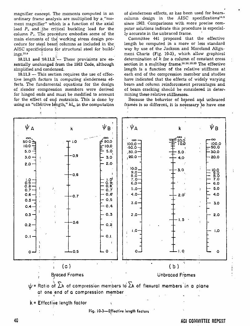
1
magnifier concept. The moments computed in an ordinary frame analysis are multiplied by a, "moment magnifier" which is a function of the axial load P,. and ithe critica! buckling load for the
ti ' column Pe. The procedure embodies sorne of the main element~ of th~ working stress design procedure for steel bearri columns as included in the AISC specific~ltions ~br structural steel for build.:.! • 10 D 1 ti mgs. · , ,,
10.11.1 an<l ¡10.11.21
':_ These provisions are essentially unchanged from the 1963 Code, although simplified and condensed.
10.11.3 - This section requires the use of effective length factors in computing slenderness effects. The fundamental equations for the design of slender compression members were derived for hinged ends and must be modified to account for the effect of enc;l restraints. This is done by using an "eff~ctive ld'ngth," kl,., in the computation
00
500 10.0 5.0
3.0
2.0
1.0 0.9 0.8 0.7 0.6 0.5
0.4
0.3
0.2
0.1
o
1 ·:
k
1.0
0.9
0.8
)
0.7
0.6
0.5 1'
(o )
1 ~raced Frames
5.0 l.
3.0
2.(}
~
l.ol 0.9;; 0.8 o.i 0.6' 0.5
0.4
0.3
0.2
O.L
o
of slenderness effects, as has been use<;]. for beamcolumn design in the AISC specifications10·n
since 1963. Comparisons with more precise computer solutions indicate this procedure is especial-ly accurate in the unbraced frame. '
Committee 441 proposed that the effective length be computed in a more or less standard way by use of the J ackson and Moreland Alignment Charts (Fig. 10-3), which allow graphical determination of k for a column of constant cross section in a m4ltibay frame. 10·10•10•13 The effective length is a function of the relative ·stiffness at each end of the compression member· and studies have indicated that the ·effects of widely varying beam and column reinforcement percentages and of beam cracking should be considered in determi~ing these relative stiffnesses.
Because the behavior of braced a~d unbraced framés is so different, it is ne~essary to have one
J ' 1
00
100.0 ·50.0 ,30.0 !20.0
10.0 9.0 B.O 7.0 6.0 5.0
' 4.0
3.0
2.0
1.0
o
k
00 l
20.0 10.0
1
5.0 4.0·
3.0
2.6
l. 5 '
l.q
( b )
Unbraced Frpmes
00
100.0 50.0 30.0 20.0
lo.g 9. 8.0 7.0 6.0 5.0
4.0
3.0
2.0
1.0
o
·' 1¡ ~ ' ~ \ji= Ratio of .L.k of compression mem.bers id L.k of flexura! membel's ·in a plane at one ·end of a compression member
t ~ 'l
k= Effective length factor :'
Fig. 1 0-3-Effective length fac:tors
40 ACI COMMITTEE REPORT
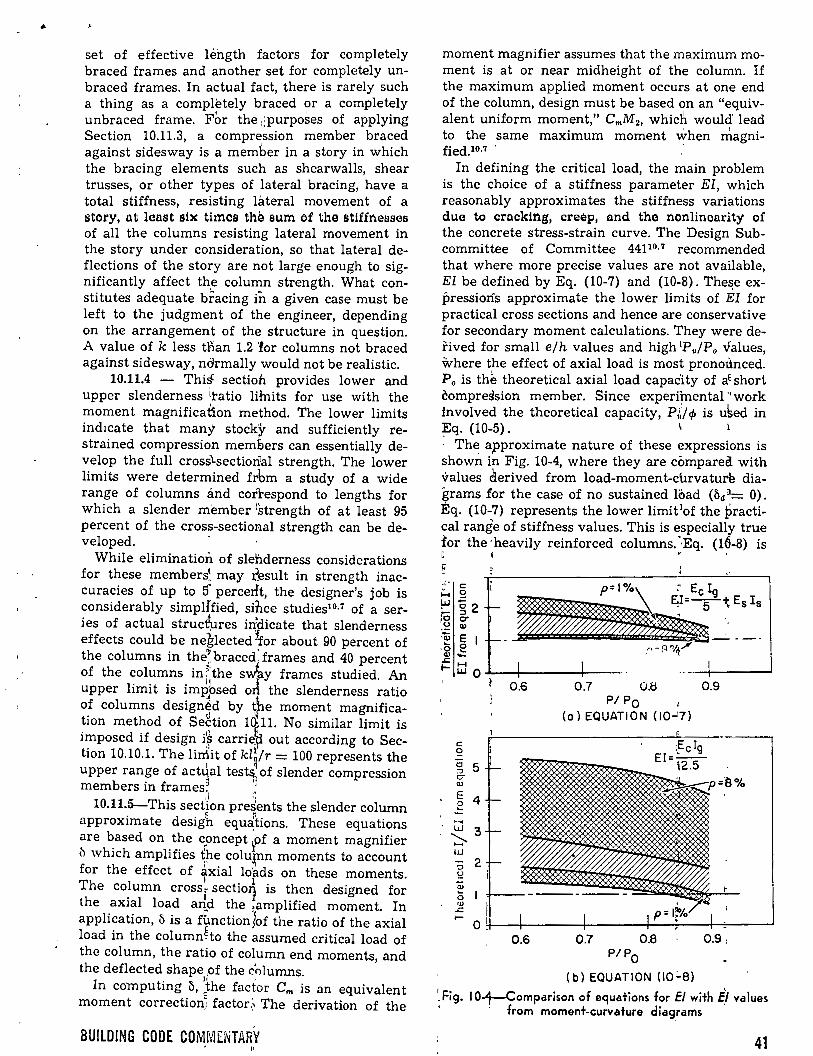
• set of effective length factors for completely braced frames and another set for completely unbraced frames. In actual fact, there is rarely such a thing as a completely btaced or a completely unbraced frame. For the :;purposes of applying Section 10.11.3, a compression member braced against sidesway is a member in a story in which the bracing elemen ts such as shearwalls, shear trusses, or other types of lateral bracing, have a total stiffness, resisting lateral movement of a story, at least shc timos thé sum of the stiffnesses of all the columns resisting lateral movement in the story under consideration, so that lateral deflections of the story are not large enough to significantly affect the column strength. What constitutes adequate bracing in a given case must be left to the judgment of the engineer, depending on the arrangement of the structure in question. A value of k less tnan 1.2 'for columns not braced against sidesway, normally would not be realistic.
10.11.4 - ThiS: sectio:h provides lower and upper slenderness itatio lilnits for use with the moment magnificatlon method. The lower limits ind1cate that many stock'y and sufficiently restrained compression memElers can essentially develop the full crosslsectiorilal strength. The lower limits were determined frbm a study of a wide range of columns ánd correspond to lengths for which a slender member ll;trength of at least 95 percent of the cross-sectional strength can be de-veloped. -
While elimination of slehderness considerations for these members~ may ~esult in strength inaccuracies of up to Ó percerlt, the designer's job is considerably simplffied, since studies1o.7 of a series of actual struc~res iqpicate that slenderness effects could be neglected 'for about 90 percent of the columns in the~braced:frames and 40 percent of the columns in r the svky frames studied. An upper limit is impbsed oJ the slenderness ratio
J, t of columns designéd by ~pe moment magnifica-tion method of Segtion 1(~11. No similar limit is imposed if design i'~ carriet; out according to Sec-. " ~ twn 10.10.1. The lirrlit of klq/r = 100 represents the
1 'l upper range of act4al test~ of slender compression members in frames~ ',
'¡ ~~ 10.11.5-This section presents the slender column
approximate desigb equ~bons. These equations are based on the concept ,pf a moment magnifier ~ which amplifies (re colu~n moments to account for the effect of 4xial lopds on these moments. The column cross, sectio~ is then designed for the axial load arid the ~amplified moment. In application, 1'> is a f~nction$of the ratio of the axial load in the columnho the assumed critica! load of the column, the ratio of column end moments, and the deflected shape ,of the c'olumns.
In computing ~. Jhe factor Cm is an equivalent moment correction) factor.~ The derivation of the
BUILDING CODE COMMENTARY
moment magnifier assumes that the maximum moment is at or near midheight of the column. If the maximum applied moment occurs at one end of the column, design must be based on an "equivalent uniform moment," CmM2 , whicft would lead to the same maximum moment when magni-fied.10·7 · ·
In defining the critica! load, the main problem is the choice of a stiffness parameter El, which reasonably approximates the stiffness variations due to cracking, creep, and tha nonlincarit;y' of the concrete stress-strain curve. The Design Subcommittee of Committee 4411°·7 recommended that where more precise values are not available, El be defined by Eq. (10-7) and (10-8). The~e expressioris approximate the lower limits of El for practica! cross sections and hence are conservative for secondary moment calculations. They were dei'ived for small ejh values and high 1P,/Po values, \\vhere the effect of axial load is most pronot\nced. P. is the theoretical axial load capac'ity of aE short compression member. Since experimental·· work involved the theoretical capacity, PU.p is u~ed in ~q. (10-5). 1 l
· The: approximate nature of these expressions is shown in Fig. 10-4, where they are cómpared with values derived from load-moment-c\.lrvature diagrams for the case of no sustained load (ba 3= O). ~q. (10-7) represents the lower limit 1of the practica! range of stiffness values. This is especially true for the ·heavily reinforced columns. ··Eq. (16-8) is l 1 • '
E
e o
g 5 17
"' E 2 4
·~ w 3 ~ w o 2 ~
0.6 0.7 O.ti 0.9 P/ Po
(o) EQUATION (10-.!.7)
0.6 0.7
~ Fig. 1 0-1-Comparison of equations for El with E,Í values ' · from moment-curvature diag_rams
41
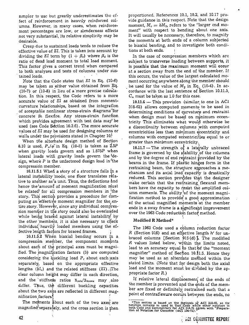
s1mpler to use but greatly underestimates the effect of reinforcement in heavily reinforced columns. However, in many cases, when reinforcement percentages ·are low, or slenderness effects not very substantial, its relative simplicity may be desirable.
Creep due to sustained loads tends to reduce the effective value of El. This is taken into account by dividing the El term by (1 + {3d) where /3d is the ratio of dead load moment to total load moment. This factor gives a correct trend when compared to both analyses and tests of columns under sus-tained loads. -
Note that the Code states that El in Eq. (10-6) may be ta~en as _either value obtained from ~q. (10-7) or (10-8) in lieu of a ·more precise calculation. In this respect, the Code refers to a more accurate value of El as obtained from momentcurvature 'relationships, based on the integraúon of acceptable nonlinear stress-strain diagrams ·cfor
· concrete in flexúre. Any stress-strain fundion which provides agreement with test data may1 be used (see eode SE!ction 10.2.6). The more accurate values of El may be used for designing columns or walls under the pr_bvisions stated in Chapter 10.t
When tne alterhate design method of Section 8.10 is usea, P,/cf/ in Eq. (10-5) is taken as 2.5P when gravity loads govern and as 1.875P when lateral loads witn gravity loads govern the rdesign, wheré P is the unfactored design load in :\he compressicin member.
10.11.5·.1 When a story of a structure fails !h a lateral instability 'mode, one floor translates r~lative to andther asra unit. Thus, the deflections ~nd hence the lamount of moment magnification must be relatecf' for all compression members in ~the story. This sectio~ provides a procedure for domputing an leffectiJ_e moment magnifier for the,entire story.'lrowev~r, since any individual comJression memBer in tQe story could also be overloáded while bei~g braced against lateral instabilitf by the other ··members, it is also necessary to cHeck individua( heavily loaded members using th~· ef-fective ledgth fadors for braced frames. ~
10.11.5 .. 2 When biaxial bending occurs fn a compressiÓn me~ber, the component mom~nts about each of thy principal axes must be m~gnified. The
1inagniffation factors (b) are computed
considerin,g the ~uckling load Pe about each ¡axis separatel)(, based on the appropriate effective lengths (~lu) and the related stiffness (El). ~The clear colu~n height may differ in each direction, and the ·:stiffness ratios ":i.colsl"ibcams may , also d1ffer. Thus, th~ different buckling capacities about the\wo axbs are reflected in different mag-nification,factors.~ ~-
The mq\nents about each of the two axes~ are magmfied?separa~ely, and the cross section is fhen
42
proportioned. References 10.1, 10.2, and 10.17 provide guidance in this respect. Note that the design moment, Me = bM2 , refers to the "larger end moment" with respect to bending about one axis. It will usually be necessary, therefore, to magnify the moments at both ends of a column subjected to biaxial bending, and to investigate both condi-tions at both ends. 1
In the case of compr'ession membe>rs which are subject to transverse loading between supports, it is possible that the maximum mo~ent will occur ata section away from the end of the member. If this occurs, the value of the largest calculated moment occurring anywhere along the member should be used for the value of M2 in Eq. (10-4). In ac-
. cordance with the last senténce of Section 10.11.5, c., must be ta~en as 1.0 for this case.
10.11.6 - This provision (similar, to one in ACI 318-63) allows computed rr10ments1 to be used in determining conditions of cprvaturr and restraint when design must be base~ on mjnimum eccentricity This eliminatés what woul~ otherwise be a discontinuity between c~lumns ~ith computed eccentricities less than minfmum '1ccentricity and columns with computed eccentricities equal to or greater than mínimum eccentricity.
10.11.7- The strength o! a lat~rally unbraced frame is governed by the stability of the columns and by the degree of end re~traint provided by the bcams in the frame. If plastic hin~es form in the restraining beam, the strusture aJ:Wroaches a mechanism and its axial load capacity is drastically reduced. This section pro0des th~t the designer make certain that the restraining: flexural members have the capacity to resist thé amplified column moments. The ability 'of the .inoment magnification method to provide1 a goodi approximation of the actual magnified mbments '1at the member ends in a sway frame is a significaht improvement over the 1963 Code reductioh facto.f method. ' ,
1
Modified R Method*
The 1963 Code used a cblumn ~eduction factor R (Section 916) and an ef(ective l~ngth h' for unbraced columns [Section 915 (d) 1~ The modified R values listed below, whhin the limits noted, lead to an accuracy equal io that lóf the "moment magnifier" method of Sedion 10J1.5. Hence they may be used as an alterriate me~hod within the stated limits. (Note that fqr design both the axial load and the moment mus't be diJided by the appropriate factor R.)
If relative lateral displ~cemen\ of the ends of the member is prevented ard the ~nds of the member are fixed or definitel~ restramed such that a point of contraflexure occ~s between the ends, no
J J - i
•This section 1s ba&ed on the rhethods o1' ACI :ua-63, so thc notatlon remains as used In that '.Code whlle other notahon In both Code and Commentary for ACI 318-71 :¡grees with "Preparatlon of Notatlon for Concrete (A(..';I 104-71) ."
~CI CÓMMITTEE REPORT t
..
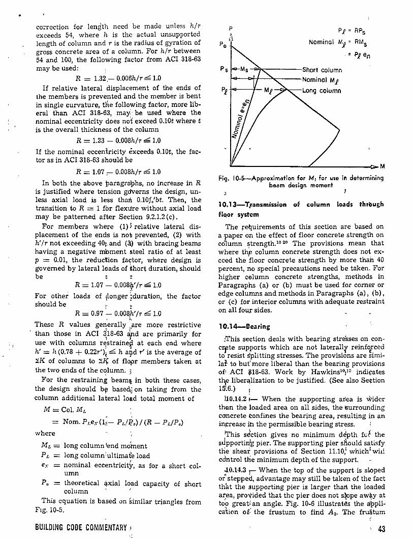
co<rection for length need be made unless hlr exceeds 54, where h is the actual unsupported length of column and r is the radius of gyration of gross concrete area of a column. For hlr between 54 and 100, the following factor from ACI 318-63
p 1 = RPs
Nominal u'i = RM5
. - Pp en
may be used: 1. Ps -'k:-----Short column R = 1.32,- 0.006hlr LI.O 14-----l~'-~---Nominal Mp
If relative lateral displacement of the ends of P¡ +ca---f-
the members is prevented and the member is bent in single curvature, the following factor, more liberal than ACI 318-63, may~¡ be used where the nominal eccentricity does not exceed O.lOt where t is the overall thickness of the column
R = 1.23 - 0.008hlr ~ 1.0
If the nominal eccentricity exceeds 0.10t, the factor as in ACI 318-63 should be
R = 1.07 , 0.008hlr .e:. 1.0
In both the above paragraphs, no increase in R is justified where tension gdverns the design, unless axial load is less that'l. 0.10fc'bt. Then, the transition to R = 1 for flexure without axial load may be patterned after Section 9.2.1.2 (e).
For members where (1) 3 relative lateral displacement of the ends is no'e prevented, (2) with h' Ir not exceeding 40:. and (3.) with bracing beams having a negative mbment steel ratio of at least p = 0.01, the reduction fador, where design is governed by lateralloads of thort duration, should be s =
R = 1.07 - 0.008~' Ir .e:. 1.0
For other loads of tlonger ~duration, the factor should be r
R = 0.97 - 0.008,h' Ir L. 1.0 ,, These R values generally are more restrictive
7 2 ' than those in ACI 318-63 éipd are primarily for
1 J use with columns r~straine~ at each end where h' = h (0.78 + 0.22r')( L. h a9d r' is the average of ~K of columns to ~~ of flopr members taken at the two ends of the cqlumn. :;
For the restraining beam~ in both these cases, the design should b~ basedj on taking from the column additional lateral load total moment of
M= Col. ML - '
Nom. Pr.es {1~- Pdi!o) 1 (R- P,jP.)
where
ML = long column fend molnent PL long column1ultimafe load
1
e.v nominal eccentricity, as for a short col-umn
Po = theoretical éÍ-Xial load capacity of short column ' r
This equation is based on similar triangles from F1g. 10-5.
BUILDING CODE COMMtNTARY ~
Fig. 10-5-Approximation for M1 for use in determining beam design moment
' 1 0.13-T,ransmission of column loads through flqor system
The refluirements of this section are based on a :paper on the effect of floor concrete strength on co1umn strength.10 20 The provisions mean that where th~ column concrete strength does not exceed the floor concrete strength by more than 40 percent, no special precautions need be taken. For higher c0lumn concrete strengths, methods in Paragraphs (a) or (b) must be used for corner or edge columns and methods in Paragraphs (a), (b), or (e) for interior columns with adequate restraint on all fou¡ sides.
1 0.14-Bearing
::-This section deals with bearing stre'sses on concrfte supports which are not laterallr reinf~rccd to resist spli tting stress es. The provisions are similat to but' more liberal than the bearing provisions of• ACI ~18-63. Work by Hawkins10¡12 indi~ates
t~ liber~lization to be justified. (See also Se4:tion 15.6.) ;
UO.l4.2 1- When the supporting ar:ea is widcr than the loaded area on all sides, the surrounding concrete tonfines the bearing area, resulting in an in~rease in the permissible bearing stress.
'This sJction gives no mínimum depth ft;t the sJpportinlg pier. The supporting pier sl\ould satisfy tne shear provisions of Section 11.10,¡ whichxwü! cdntrol tlle mínimum depth of the support.
rl-0.14.3 .--- When the top of the support is sL<i>ped ~ ' or stepped, advantage may still be taken of the fact
thlü the supporting pier is larger thart. the loaded ar,ea, proV.ided that the pier does not s~pe aw~y at too greati' an angle. Fig. 10-6 illustrates the a'pplica1ion of.' the frustum to find A2. The fru§tum
'43
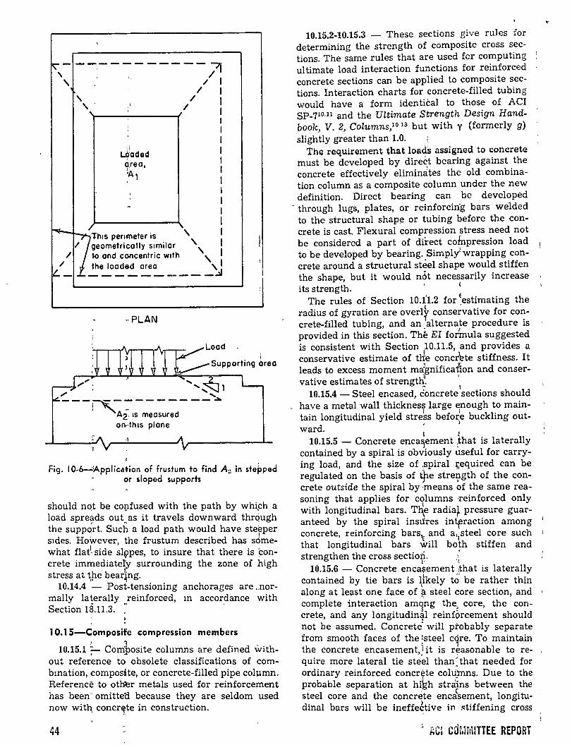
""- --.--------- :7f ' ' ,¡ / ' / /
' / ' / '~----~------~
/ geometricolly s1milor ', ~~Th1s penmeter is '
/ ro ond concentric w1th '
~/- ~~0~8~~~----~
"PLAN
.. ... ; .......... , ... ..... ---~--------·
' Ai 1s meosured on"thiS plone
1
1
J
Fig. 1 0-6-:.~pplication of frustum to find A2 in ste~ped or sloped supports
should noJ be covfused with the path by whtch a load spreads out as it travels downward through the suppq~t. Sucl~ a load path would have ste~per s1des. Ho~ever, the frustum described has sdmewhat flat1
- side sl9pes, to insure that there is ~oncrete immediatel'y surrounding the zone of high stress at t"he bear~ng.
10.14.4 - Post-tensioning anchorages are .. normally laterally reinforced, m accordance with Section 1B.ll.3. "
1 0.1 5-Composife compression members ' 1 10.15.1 ;- Composite columns are defined with-
out refetence to obsolete classifications of combmation, <:omposite, or concrete-filled pipe column. Reference to ot~r metals used for reinforcement has been- omitte<:l because they are seldom used now with, concrftte in construction.
44
10.15.2-10.15.3 - These sections give rules for determining the strength of composite cross sections. The same rules that are used fcr computing ultimate load interaction functions for reinforced concrete sections can be applied to composite sections. Interaction charts for concrete-filled tubing would have a form identical to those of ACI SP-71o.11 and the Ultimate Strength Design Handbook, V. 2, Columns,1° 13 but with .:i (formerly g) slightly greater than 1.0. i
The requirement that loads assigned to concrete must be developed by direct bearing against the concrete effectively elimindtes the old combination column as a composite column under the new definition. Direct bearing can be developed
· through lugs, plates, or reinforcin·g bars welded to the structural shap!;:! or tubing befare the concrete is cast. Flexura! compression stress need not be considered a part of dÜ:ect cotnpression load to be developed by bearing. Simply~ wrapping concrete around a structural steel shape would stiffen the shape, but it would nót necessarily increase its strength. ' <
The rules of Section 10.Ú.2 for ~estimating the radius of gyration are overlf conservative for concrete-filled tubing, and an _alternate procedure is provided in this section. Th~ El formula suggested is consistent with Section 10.11.5, and provides a conservative estímate of ule conc~te stiffness. It leads to excess moment mignificat'í.on and conser-vative estimates of strength~ ·
o 1 10.15.4 - Steel encased, c"oncrete sections should
have a metal wall thickness large ~nough to maintain longitudinal yield streks befor'e buckling out-
)
ward. 1
¡
10.15.5 - Concrete enca~ement ~hat is laterally contained by a spiral is obviously useful for carrying load, and the size of ,spiral :r,equired can be regulated on the basis of tpe stre9-gth of the concrete outside the spiral by ·means of the same reasoning that applies for columns ·reinforced only
L with longitudinal bars. The radia~ pressure guar-anteed by the spiral insJres intrraction among . concrete, reinforcing bars'E and ar
1steel core such 1
that longitudinal bars will both stiffen and strengthen the cross sectiori. .'
L• .¡
10.15.6 - Concrete enca~ement 'ithat is laterally contained by tie bars is likely tÓ be rather thin
' along at least one face of ~ steel ~ore section, and complete interaction amqng the, core, the concrete, and any longitudin~l reinfórcement should not be assumed. Concrete' will ptobably separate from smooth faces of the ;steel cqre. To maintain the concrete encasement, 1 it is reasonable to require more lateral tie ste~l than\hat needed for ordinary reinforced concrete coh.fmns. Due to the probable separation at h~h stra~ns between the
' ( steel core and the concrete encasement, longitu-dinal bars will be ineffe~tive in. ~tiffening cross
' AGl cd~JMITTEE REPORT
sections even though they would be useful in sustaining compression forces. Finally, the yield strength of the steel core should be limited to that which exists at strains below those that can be sustained without spalling of the concrete encasement. It has been assumed that axially-compressed' concrete will not spall at strains less than 0.0018. The yield strength of 0.0018 X 29,000,000, or 52,-' 000 psi, represents an upper limit of the useful maximum steel stress.
1 0.16-Special provisions for walls
This section recognizes that bearing walls can be designed as compression members. The unique reinforcement requirements for walls are included. Ties may be eliminated for steel ratios less than O.OlAu or when the vertical reinforcement is not required to resist compression stress. All other provisions for compression members must be satisfied.
References 10.1. Weber, D. C., "Ultimate Strength Design Charts
for Columns with Biaxial Bending," ACI JouRNAL, Proceedings V. 63, No. 11, Nov. 1966, pp. 1205-1230.
10.2. Parme, A. L.; Nieves, J. M.; and Gouwens, A., "Capacity of Reinforced Rectangular Columns Subjected to Biaxial Bending," ACI JoURNAL, Proceedings V. 63, No. 9, Sept. 1966, pp. 911-923.
10.3. Gergely, P., and Lutz, L. A., "Max1mum Crack Width in Reinforced Concrete Flexura! Members," Causes, M echanism, and Control of Cracking in Concrete, SP-20, American Concrete Institute, Detroit, 1968, pp. l-17.
10.4. Kaar, P. H., "High Strength Bars as Concrete Reinforcement, Part 8: Similitude in Flexura! Cracking of T-Beam Flanges," Journal, PCA Research and Development Laboratories, V. 8, No. 2, May 1966, pp. 2-12. Also, Development Department Bulletin D106, Portlahd Cement Association.
10.5. Base, G. D.; Reed, J. B.; Beeby, A. W.; and Taylor, H. P. J., "An Investigation of the Crack Control Characteristics of Various Types of Bar in Reinforced Concrete Beams," Research Report No. 18, Cement and Concrete . Association, London, Dec. 1966, 44 pp.
10.6 Lloyd, John P.; Rejali, Hassen M.; and Kesler, C. E., "Crack Control in One-Way Slabs Reinforced with Deformed Wire Fabric," ACI JouRNAL, Proceedings V. 66, No. 5, May 1969, pp. 366-376.
10.7. MacGregor, James C.; Breen, John E.; and Pfrang, Edward 0., "Design of Slender Concrete Columns," ACI JouRNAL, Proceedings V. 67, No. 1, Jan. 1970, pp. 6-28. '
10.8. Ferguson, Phil M., "Long Columns in Frames~ Computer Analyses, Part 4: Code Recommendations" University of Texas at Austin, Oct. 1968, 16 pp. '
10.9. "~ommentary and Specifications for the Design, Fabncaüon, and Erection of Structural Steel for Buildings," American Institute for Steel Construction, New York, 1969.
10.10. "Guide to Design Cnteria for Metal Compressien .Members," Column Research Council, Fritz Enginecnng Laboratory, Bethlehem, Pa., 2nd Edition, 1966.
BUILDING CODE COMMENTARV
10.11. Everard, Noel J., and Cohen, Edward, lJLttma~e Strength Destgn of Remforced Concrete Columns, SP-7, American Concrete Institute, Detroit, 1961, 1G2 pp.
10.12. Hawkins, N. M., "The Bearing Strength of Concrete Loaded Through Rigid Plates," Magazine of Concrete Research· (London), V. 20, No. 62, Mar. 1968, pp. 31-40.
10.13. ACI Committee 340, Ultima.te Strength Design Handbook, V. 2, Columns, SP-17A, American Concrete Institute, Detroit, 1970, 226 pp.
10.14. Whitney, Charles S., "Plastic Theory of Reinforced Concrete Design," Transactions, ASCE, V. 107, 1942, Pll• 251-326,
10.15. ACI-ASCE Committee 327, "Ultimate Strength Design," ACI JouRNAL, Proceedin.gs V. 52, No. 5, Jan. 1956, pp. 504-524.
10.16. Whitney, C. S., and Cohen, Edward, "Guide for Ultimate Strength Design of Reinforced Concrete," ACI JouRNAL, Proceedings V. 53, No. 5, Nov. 1956, pp. 455-490.
10.17. Bresler, Boris, "Design Criteria for Reinforced Concrete Columns Under Axial Load and Biaxial Bending," ACI JouRNAL, Proceedin.gs V. 57, No. 5, Nov. 1960, pp. 481-490.
10.18. Mattock, A. H.; Kriz, L. B.; and Hognestad, E., "Rectangular Concrete Stress Distnbution in Ultimate Strength Design," ACI JOURNAL, Proceedings V. 57, No. 8, Feb. 1961, pp. 875-928. Also Development Department Bulletin D49, Portland Cement Association.
10.19. Hansell, William, and Winter, George, "Lateral Stability of Reinforced Concrete Beams," ACI JouRNAL, Proceedings V. 56, No. 3, Sept. 1959, pp. 193-214. (Discussion Mar. 1960, pp. 957-967). Also, Sant, Jagadish K., and Bletzacker, Richard W., "Experimental Study of Lateral Stability of Reinforced Concrete Beams," ACI JoURNAL, Proceedings V. 58, No. 6, Dec. 1961, pp. 713-736.
10.20. B1anchini, Albert C.; Woods, Robert E.; and Kesler, Clyde E., "Effect of Floor Concrete Strength on Column Strength," ACI JouRNAL, Proceedings V. 56, No. 11, May 1960, pp. 1149-1169.
10.21. "Reinforced Concrete Column InvestigationTentative Final Report of Committee 105," ACI JouRNAL, Proceedings V. 29, No. 5, Feb. 1933, pp. 275-282.
10.22. Nawy, Edward G., "Crack Width Control in Welded Fabric Reinforced Centrally Loaded Two-Way Concrete Slabs," Causes, Mechanism, . and Control of Cracking in Concrete, SP-20, American Concrete Institute, Detrolt, 1968, pp. 211-235.
10.23. Nawy, Edward G., and Orenstein, G. S., "Crack Width Control in Reinforced Concrete Two-Way Slabs," Proceedings, ASCE, V. 96, ST3, Mar. 1970, pp. 701-721.
10.24. Nawy, Edward G., and Blair, Kenneth W., "Further Studies on Flexura! Crack Control in Structural Slab Systems," Cracking, Deflection, and Ultimate Load of Concrete Slab Systems, SP-30, American Concrete Institute, Detroit, 1971.
10.25. Furlong, R. W.,· "Design of Steel Encased Concrete Beam-Columns," Proceedings, ASCE, V. 94, STl, Jan. 1968, pp. 267-281.
10.26. Faber, 0., "Savings to be Effected by the More Rational Design of Encased Stanchions as a Result of Recent Full Size Tests," The Structural Engineer (London), V. 34, No. 3, Mar. 1956, pp. 88-109.
10.27. Malhotra, H. L., and Stevens, R. S., "Fire Resistance of Encased Stanchions," Proceedings, Institution of Civil Engineers (London), V. 27, Jan. 1964, pp. 77-98.
45
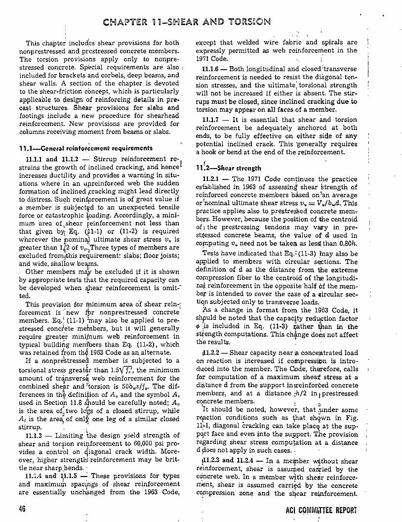
' This chapter includ
1es shear provisions for both
nonprestressed and prestressed concrete members. The torsion provisions apply only to nonprestressed concrete. Special requirements are also 1
included for brackets and corbels, deep beams, and shear walls. A section of the chapter is devoted to the shear-friction ci:mcept, which is particularly applicable to design of reinforcing details in precast structures. Shear provisions for slabs and footings include a new procedure for shearhead reinforcement. New provisions are provided for columns receiving moment from beams or slabs.
11.1-Ceneral reinforcement requirements
11.1.1 and 1~.1.2 -· Stirrup reinforcement restrains the growth of ínclined cracking, and hence~ increases ductility and provides a warning in situations where Ú1 an upreinforced web the sudden formation of inclíned Fracking might lead directly to distress. Su~h reinfprcement is of great value if a member is ¡;ubject~d to an unexpected tensile force or catastrophic )f>ading. Accordingly, a minimuro area of ,shear feinforcement not less than that given byi Eq. (tl-1) or (11-2) is required wh.erever the pomina,I ultimate shear stress v,. is greater than 1~2 of Vc·¡Three types of members are excluded fromJthís requírement: slabs; floor joists; and wide, shallow beaps.
. Other memi:Jers méo/ be excluded if ít is shown by appropriate tests that the required capacity can be developed when ~ear reinforcement is omit-ted.
This provision for I):linimum area of shear rein-~ forcement is ,. new :fbr nonprestressed concrete· members. Eq.,1• (11-1) \nay also be applied to prestressed concrete meinbers, but it wíll generally require greater mínijnum web reinforcement in typical buildirtg merrlbers than Eq. (11-2), which was retained lrom th~ 1963 Codeas an alternate.
If a nonpre~tressed member is subjected to a torsional streli1S great~r than 1.5'/--r/, the mínimum amount of tr~nsvers' web reinforcement for the combined shear and torsíon is 50bws/f11 • The differences in th~ definqion of Av and the symbol A 1
used in Sectio,p 11.8 ~t,ould be carefully noted; Av is the area ofJ two lec~s of a closed stirrup, while At is the area:. of only one leg of a similar closed stirrup. · .'
• 11.1.3 - Limiting the design yield strength of shear and tor~ion rei!fforcement to 60,000 psi provides a control on qiagonal crack width. Moreover, higher strengthl reinforcement may be brittle near sharp¡bends. ·
' j
11.1.4 and ~1.1.5 ---: These provisions for types and maximum spac\ngs of shear reinforcement are essentiall~ unch.anged from the 1963 Code,
46
except that welded wire fabric and spirals are expressly permitted as web reínforcerilent in the 1971 Code. ·
11.1.6 - Both longitudinal and closed :transverse reinforc.ement is needed to resist the diagonal tension stresses, and the ultima te; torsional strength will not be increased if eíther is absent. The stirrups must be closed, since inclined cracking due to torsion may appear on all faces of a member.
11.1.7 - It is essential that shear and torsion reinforcement be adequately anchored at both ends, to be fully effective on either side of any potential ínclined crack. This ·generaliy requires a hook or bend at the end of the reinforcement.
1 11 :2-Shear strength
11.2.1 - The 1971 Code continues the practice established in 1963 of assessing' shear strength of refnforced concrete members based onnan average or 7nominal ultimate shear stress v,. = V,./bwd. This practice applies also to prestressed concrete members. However, because the position of the centroid of J the prestressing tendons may va:ry in prestl]essed concrete beams, the value of d used in co~puting v,. need not be taken as lessl than 0.80h.
Tests have indicated that Eq.: (11-3) lnay also be aJ:Wlied to members with circular sections. The definition of d as the distance from the extreme compression fiber to the centro~d of t~ longitudina~ reinforcement in the opposite half óf the membe¡r is in tended to cover the case of a <drcular sectíqn subjected only to transverse loads.
"As a change in format from the 1963 Code, it shf.ul~ be noted that the capacity red~ftion factor ~ ;IS mcluded in Eq. (11-3) :¡;ather t¡han in the strength computations. This change does not affect the resul ts. "
H.2.2- Shear capacity near ;8. conceiJlltrated load on reaction is increased if colinpressit>n is introduced into the member. The Code, thEU"efore, calls for computation of a maximum shea:t stress at a distance d from the support in~einforted concrete members, and at a distance :h/2 in¡ prestressed concrete members. .
' • D lt should be noted, however, that ¡}lnder sorne rerction condi~ions such as ~,hat sh'ilwn in Fig. 11,¡-1, diagonal cracking can take placE{ at the supp~rt face and even into the sul?port. The provision regarding shear stress computation at a distance d poes not apply in such cases. ·,
!~1.2.3 and 11.2.4 - In a melj!lber ~thout shear r~mforcemen t, shear is assuq:ted carified by the concrete web. In a member with shear reinforcement, shear is assumed carri~d by the concrete . , c~mpress10n zone and the s~ear reinforcement.
ACl C9\VJMLTTEE REPORT
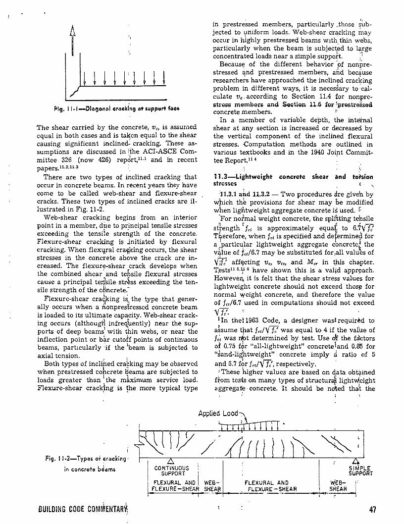
Flg. 11-1-0iagonal eracki~g at auppe~ft fae11
The shear carried by the concrete, Ve, is assumed equal in both cases and is ta~en equal to the shear causing significant inclined- cracking. These assumptions are discussed in i,the ACI-ASCE Committee 326 (now 426) repdrt,11·1 and in recent papers.n.2.1L3 t•
There are two types of inclined cracking that occur in concrete beams. In recent years they have come to be called web-shear and flexure-shear cracks. These two types of inclined cracks are illustrated in Fig. 11-2.
Web-shear cracking begins from an interior point in a member, dhe to principal tensile stresses exceeding the tensiie streñgth of the concrete. Flexure-shear cracking is ..lnitiated by flexura! cracking. When flexq,ral crac¡;king occurs, the shear stresses in the concrete above the crack are increased. The flexure-shear crack develops when the combined shear · and tebsile flexural stresses cause a principal terfsile str~ss exceeding the tensile strength of the c8ncrete.~
Flexure-shear cra¿f:ing is the type that generally occurs when a nonpresfressed concrete beam is loaded to its ultimate capacity. Web-shear cracking occurs (althougH infreq_\rently) near the supports of deep beams1 with thin webs, or near the inflection point or b~r cutoff points of continuous beams, partlcularly 1if the 1beam is subjected to axial tension. .
Both types of inclihed crabking may be observed 1 ., when prestressed concrete oeams. are subjected to loads greater than 1 the m1ximum service load. Flexure-shear crack~ng is !he more typical type
1
Fig. 11-2-Types or cracking·
in concrete b~ams LS
CONTINUOUS SUPPORT
l 1¡
in prestre¡;sed members, particularly .those ~).lb-
jected to l,miform loads. Web-shear cr:3;cking may occur in hÍghly prestressed beams wlth thin webs,
1
particularly when the beam is subject.~d to large concentrated loads near a simple suppoft. :1
¡, 11
Because of the different behavior of nonpre-, ,1 ,_
stressed and prestressed members, and because ' ' 1
researchers have approached the inclin!'!d crac~ing problem in different ways, it is necessary to calculate Ve, according to Section 11.4 for nonprestress members ami Sestign 11.6 fgr \prestresseti concrete members. r·
In a member of variable depth, the intei:nal shear a t any section is increased or decreased by the vertical component of the inclined flexura! stresses. -computation methods are outlined in various textbooks and in the 1940 Joip.t Com¡:nittee Report,ll 4
>,
' 11.3-Lightweight concrete shear and torsion stresses , E . ,
11.3.1 arid 11.3.2 - Two procedures are giveh by which thk provisions for shear may be modified when ligntweight aggregate concrete is used. r.
'For normal weight concrete, the splitting tehsile sfrength r fct is approximately equal~ to 6.7y fe'
( < ~
T~erefore, when fct is specified and deferminea for a _partic~lar lightweight aggregate concrete~ the v~lue of fct/6.7 may be substituted for,all values of
YJfc' aff~cting Ve, Vtc, and Mcr in ~pis chapter. T1ests11 5·V 6 have shown this is a val~d appr9ach. !ipwever,, it is felt that the shear stress values for hghtweight concrete should not excef'!d thosJ! for normal weight concrete, and therefore the value of fct/6.7 used in computations should not exceed y fe'.
1 In the: 1963 Code, a designer wast requiréd to ~ - .
assume that fct!Y fe' was equal to 4 if the val'ue of fc't was n~t determined by test. Use o!f the f::ktors of 0.75 for "all-lightweight" concreteland 0.85 for "sand-lidhtweight" concrete imply ~ ratio' of 5
l - ' a~d 5.7 fpr fct!Y fe', respectively. ' •These higher values are based on elata obt~ined
ffom tests on many types of structuraB. lightW.eight ' l }
aggrega~~· concrete. It should be noted that the
SIMPLE SURPORT
FLEXURAL ANO WEB- FLEXURAL ANO WEB- ¡: ~FL_E_X_U_R_E_-_S_H~E-AR~~·--E~A~~+---~-F_L_E_XURE-S_H_E_A_R ___ -+•••-S-~~.E_A_R--~1
1 1
BUILDING CODE COMMENTAR~ 47
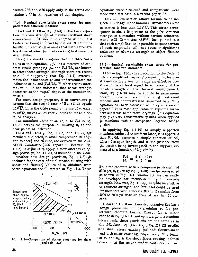
factors 0.75 arid 0.85 apply only to the terms containing Yfc' in the equations of this chapter.
11.4-Nominal permissible shear stress for nonprestressed concrete members
11.4.1 and 11.4.2 - Eq. (11-4) is the basic equation for shear s"treng¡~h o~ members w~thout shear reinforcement. It was flrst adopted m the 1963 Code after being endbrsed by ACI-ASCE Committee 326. This equatiori assumes that useful strength is exhausted when iriclined cracking first develops
b 1,
inamem er. 1
Designers should recognize that the three vari-ables in this ,equatio~, YTc' (as a measure of concrete tensile ~trength), pw, and Vud!Mu, are know~ to affect shear strength, although there are recent datatL7,u.R suggesting that Eq. (11-4) overestima tes the influence rof fe' and underestimates the influence of P•o and 'fud/Mu. Further recent information11 °·11·10 has indicated that shear strength decreases as 3the ov~rall depth of the member in-creases. r
For most p.esign purposes, it is convenient ~o assume that :the secpnd term of Eq. (11-4) equals 0.1\'f?. Thu!t1 the C4de permits the use of Vo equ~l to 21/ fe', unl~ss a designer chooses to make a de-tailed analysis. 1 1
The mínimum value of M,. equal to V,.d in Eq. (11-4) serves the purpose of limiting Ve at and near points ::of inflection.
11.4.3 andE 11.4.4 r Eq. (11-5) and (11-7), fpr members s~bjected1 to axial compression in ad<?ition to shear and fl~xure, are derived in the AC~ASCE Co~mittee: 326 report.11 ·1 Because :E{q. (11-5) is dificult t~ apply, a new alternative C\esign provisi9n, Eq. j11-6), is included in the Code.
Another new d~ign provision, Eq. (11-8), ¡is included for the ca~e of axial tension exi!?ting wi¡_th shear and hexure: Values of Ve obtained from these equat~ons ar~ illustrated in Fig. 11-3. Th~¡;e
1 i
Shoded oreo shows approx. : ronge of va lue~ obto1ned from Eq {11-4) ond Eq.{ll-5) 1•
1000
\
1 COMPRESSION
500
Nu/Ag , psi
6 ~
5 .flc
-<Eq (11-Sli
1 " 1
TENSio'N, j
Fig. 11-3-Compariton of design equations for sl\ear ' ( and axial load
48
equations were discussed and compansons were made with test data in a recent paper.11·3
11.4.5 - This section allows torsion to be neglected in design if the nominal, ultima~e stress due to torsion is less than 1.51/17. This stress corresponds to about 25 percent of1the PU:~e torsional strength of a member withou~ torsio~ reinforcement. ACI Committee 43811·1f has pointed out that such simplification is poss~ble be~~use torsion of such magnitude will not ;~ause a; significant reduction in ultimate strength in eit;her flexure or shear.
11.5-Nominal permissible shear stress for prestressed concrete members . .
11.5.1- Eq. (11-10) is an addition to the Code. It offers a simplified means of computing Ve for prestressed concrete beams having an effective prestress force at least equal td 40 percent of the ténsile strength of the flexural reinforcement. Thus, Eq. (11-10) may be applied td sorne members reinforced with a combination o.f prestressed ~ndons and nonprestressed deformep. bars. This ~quation has been discussed ~n detai¡ in a recent
. paper.11 ·3 It is most applicab1:e to bttilding memqers subjected ,to uniform loap.ings. '.l(his equation may give very conservative ~sults rvhen applied ~o members such as compo~ite 1-s~ction bridge girders.
In applying Eq. (11-10) to simply supported members subjected to uniforJJjlloads, ~t is apparent that V,.d/M,. becomes a simple function of djl, where l is span length, and·]r, the pistance from yhe section being investigate~ to th~ support, expressed as a function of l, given by: ,
V,.d d (t...:: 2x) Mu =X (l ~ x)
' ¡
.Thus for concrete with a compressi~e strength of pOOO psi, v. given by Eq. (11-ID) can ~e represented \as shown in Fig. 11-4. Simi\ar figu;es can easily ¡be developed for members of o!her concrete ,strength. However, Eq. (ll-1p) is qtfJ.te insensitive :to concrete strength, and Fi:g. 11-4 tcould be used for members with concrete ~rengt}f ranging from
.-4000 to 6000 psi with an error of less than 10 per.::ent.
11.5.2 and 11.5.3- These sections~give the basic · rlesign provisions for determining Ve for pre-~tressed concrete beams. f:xcept ~ for a minor
'change in Eq. (11-11), and c~nversiqn toa nominal \stress basis, these provisioris are tpe same as in ¡the 1963 Code. Eq. (11-11) ap.d Eq. ¡(11-12) predict i the shear stress causing :tnclined·· flexure-shear ~ and web-shear cracking, réspectiv~ly. The lesser ~ of Ve¡ and Vcw is the shear ~tress clusing inclined ~cracking at the section unáer con~ideration, and
~CI CO~MITIEE REPORT
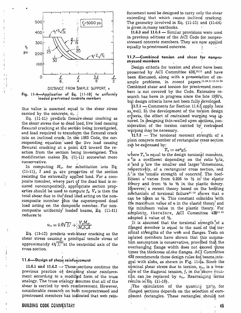
• 1
\ l
. ' ¡
500
400
300 ve
PSI 200
lOO
o
(vc=5v1~
;; 1 f~=5000 ps11 j
.l 4
31 8
DISTANCt: FROM SIMPLE SUPPORT, x
_g_ 2
Fig. 11-4-Application of Eq. ( 11-10) to uniformly loaded prestressed concrete members
th1s value is assumed equal to the shear stress carried by the concrete, Ve. , 1
Eq. (11-11) predic4 flexu;re-shear cracking as the shear stress due to dead ~9ad, live load causing flexural cracking at ti1e secti~n being investigated, and load required to ·transfo!'m the flexural crack into an inclined crack. In tlie 1963 Code, the corresponding equation 'used tp.e live load causing flexural cracking at a point d/2 toward the reaction from the section being investigated. This modification makes ~q. (11_-11) somewhat more conservative. .
In computing Mcr for substitution into Eq. (11-11), I and y 1 a!'e pro~rties of the section resisting the externally app!ied load. For a composite member, wherr part ~f t~e dead l?ad is resisted noncompositely, appropnate sect10n properties should be u sed to compute fa· V a is then the total shear due to the( dead lóad acting on the noncomposite member plus the superimposed dead load acting on the ¿omposite member. For noncomposite uniformlyr loaded beams, Eq. (11-11) reduces to
d 1-f 1 :. V,.Mcr Ve¡ = O.o.\ r + 1 M,.bwd
Eq. (11 .. 12) predicts web-shear cracking as the shear stress causing a principal tensile stress of approximately 4Yf7Jat the centroidal axis of the cross section.
r ' 11.6-Design of shea~ reinfo~cement
11.6.1 and 11.6.2 __. These>sections continue the previous practice o~ desig~ing shear reinforcemen t accordmg to a modif~d form of the truss analogy. The truss arlalogy ébssumes that all of the shear is carried by \yeb remforcement. However, considerable research on both nonprestressed and prestressed members has in~icated that web rein-
BUILDING CODE COMMENTARY "
forcemen t need be designed to carry only the shear exceeding that which causes inclined crackmg. The geometry involved in Eq. (11-13) and (11-!14) is given in,,many textbooks. 1
11.6.3 and 11.6.4 - Similar provisions, were used in previo~s editions of the ACI Code for nonprestressed c~ncrete members. They are npw app,Ved equally to:prestressed concrete.
11'.7-Combined torsion and shear for non~rcstressed members
1
Design criteria for torsion and shear have been presented by ACI Committee 438,11·11 and have been discussed, along with a presentation of example problems, in recent papers.11·12•11 13•11. 26
Combined shear and torsion for prestressed,members is not covered by the Code. Extensive reseF~rch has been in progress since the ,late 19
160's,
b~t design criteria have not been fully ¡develoB_ed. p.7.1: Comments for Section 11.4.~ apply ?ere
as well. In the developmen t of the to~sion design crlteria, t~e effect of restrained warP¡~n~ wa~ ignored. In designing thin-walled open S'fctwns, ~onsü;ieration~ of the torsion carried bY:, restraJned
l ' b 1 wy.rping may e necessary. 1
11.7 .2 - The torsional momen t strength of a plain concrete member of rectangular ~ross se~tion cap be ex~ressed by:
T,. = UX2Yft where T,. \s equal to the design torsion~l mom~nts, a Eis a coefficent depending on the ratio "l.y/x, x 1and y 1are the smaller and larger 1 dimens~ons, re1pectively of a rectangular cross section, and
1 , « ~ f 1 ' is the 'tensile strength of concret~. The l:Oef-ficient a ( varies from 0.208 to 1/a in' the elastic th<eory arid from lfa to lfz in the pla,stic théory. Hbwever,~ a recent theory based on the be~ding m~chanism of torsional failure1112 sl\ows that a can be t~ken as 1/a. This constant c~fncides ~\vith tlle maxihmm value of a in the elastlc theory and tl\e minihmm value in the plastic theory.' For sifnplicity, therefore, ACI Committee 4331111
- )
adopted a value of Va. . e 'It is assumed that the torsional s~rength. of a
fl~nged tnember is equal to the sum of the; torsi'bnal stfengths of the web and flanges. Tests on isflated members have shown that this summation assu~ption is conservative, provfded tha~ the
~ { ~
[email protected] flange width does not ~xceed three ti~es th~ thickness of.the flanges. ACJ Comrrlittee 438 recorhmends these design rules fo~ beams~integral with slabs, as shown in Fig. 11-cla. Since the n~minal 9hear stress due to torsion, ~~'" is a .ineas~re of the 'diagonal tension, fe in the 1above equa-
' l ti?n can '.be replaced by v1,.. Rearrangmg terms results i~Eq. (11-16). ~The c~lculation of the quantJty 'i_x~y~ for
fl'anged sections depends on the seleélion of .comp~ment ~ectangles. These rectangles'
1 shou14, not
49
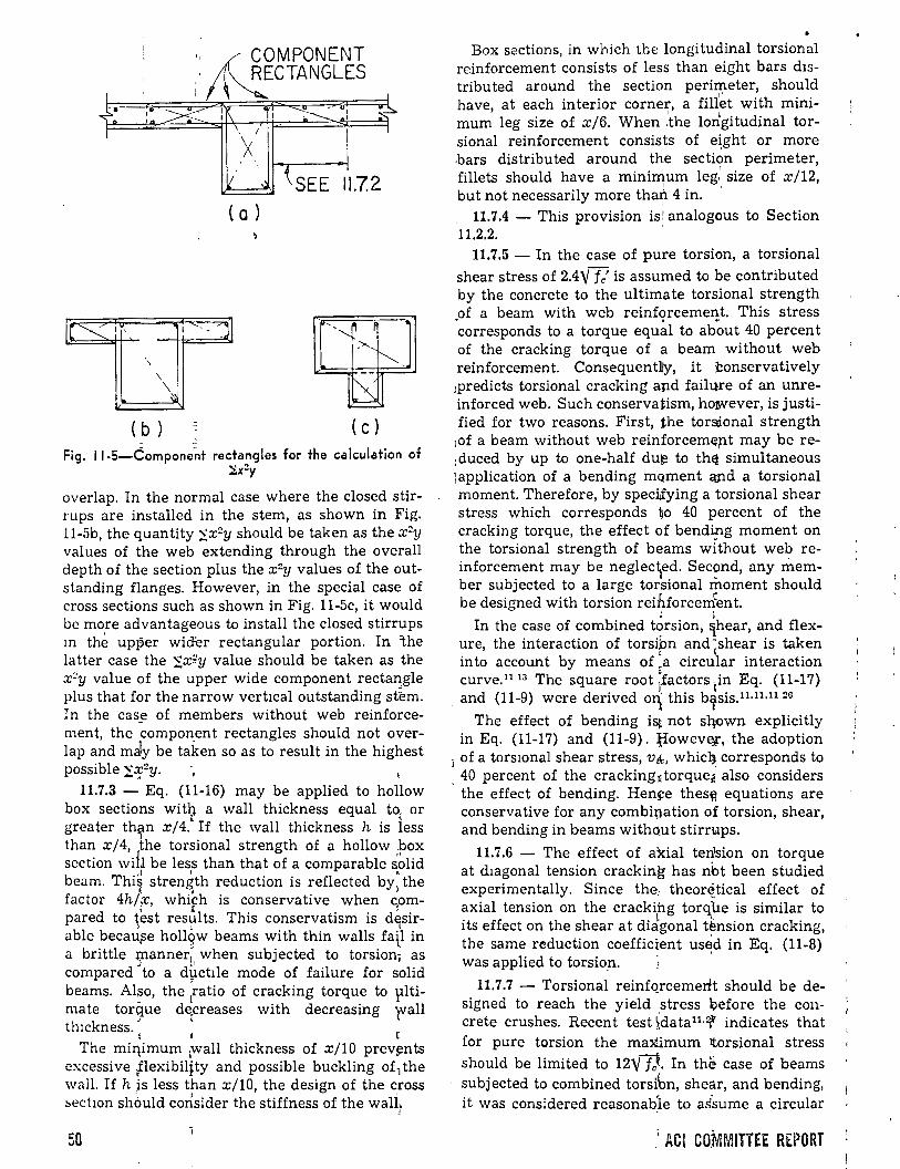
le~·,
\
\
\ ( b )
.: ~OMPONENT · RECTANGLES
'1 1•
SEE 11.72 ( a )
(e) - -
Fig. 11-5-Compone~t rectangles for the calculation of :Sx2y
overlap. In the normal case where the closed stirrups are installed in the stem, as shown in Fig. 11-5b, the quantity 'i_x2y should be taken as the x 2y values of the web extending through the overall depth of the section plus the x 2y values of the outstanding flanges. However, in the special case of cross sections such as shown in Fig. 11-5c, it would be more advantageous to install the closed stirrups m the upper wicfer rectangular portion. In ~he latter case the 'i,x~y value should be taken as the x:!y value of the upper wide component rectan,gle plus that for the narrow vertical outstanding st~m. In the case of members without web reinforcement, the component rectangles should not overlap and mély be taken so as to result in the highest possible 'i,:xf!y.
11.7.3 - Eq. (11-16) may be applied to hollow box sections wit? a wall thickness equal t<>r or greater than x/4. If the wall thickness h is less
1 . than x/4, the torswnal strength of a hollow box section wih be less than that of a comparable s~lid
.J 1 A.
beam. Thi~ stren&th reduction is reflected by) the factor 4h/¡x;, which is conservative when c.om-
, ! . pared to ~est results. This conservatism is d~sir-
able becaú,se hollqw beams with thin walls fa\1 in a brittle -)l'lanner~ when subjected to torsion1 as compared to a d\lctlle mode of failure for solid beams. Also, the ratio of cracking torque to plti-
- l mate torque de.creases with decreasing )Vall th1ckness. ' '
1 1
The miljimum 1wall thickness of x/lO prev~nts excessive Jlexibiljty and possible buckling of1 the wall. If h is less than x/10, the design of the cross
' ' ' ~ectwn shóuld consider the stiffness of the wall-
j
50
Box sections, in which the longitudinal torsiona1 reinforcement consists of less than eight bars distributed around the section perimeter, should have, at each interior corner, a fill~t with mínimum leg size of x/6. When :the lorlgitudinal torsional reinforcement consists of e~ght or more .bars distributed around the section perimeter, fillets should have a mínimum leg.' size of x/12,
1 '
but not necessarily more tha~ 4 in. 11.7.4 - This provision is! analogous to Section
11.2.2. '
11.7.5 - In the case of pure torsion, a torsional shear stress of 2.4'/ fe' is assumed to be contributed by the concrete to the ultimate torsional strength .of a beam with web reinf<;>rcemeJ!t. This stress corresponds to a torque equal to about 40 percent of the cracking torque of a beam without web reinforcement. Consequentlly, it :Conservatively
¡predicts torsional cracking and failure of an unreinforced web. Such conservatism, however, is justified for two reasons. First, the tor$onal strength
1of a beam without web reinforcem~pt may be re:duced by up to one-half du~ to th~ simultaneous ]application of a bending mQment qpd a torsional momen t. Therefore, by speci¡fying a torsional shear stress which corresponds ~o 40 percent of the cracking torque, the effect of bendi[lg moment on the torsional strength of beams without web reinforcement may be neglec\ed. Sec9nd, any member subjected to a large torsional moment should be designed with torsion reihforcenfent.
In the case of combined t?rsion, ~hear, and flexure, the interaction of torsipn and ~shear is taken into account by means of ,a circular interaction curve.U 13 The square root ;tactors 1in Eq. (11-17)
1 and (11-9) were derived on¡ this b:rsis.U·11•11 zn
The effect of bending is~ not sqown explicitly in Eq. (11-17) and (11-9). ~owev~. the adoption
i of a torswnal shear stress, v&, whicij, corresponds to 40 percent of the crackingEtorque~ also considers the effect of bending. Hen~e thes~ equations are conservative for any combiiJation of torsion, shear, and bending in beams witho,ut stirr~Ups.
11.7.6 - The effect of axial tension on torque at diagonal tension cracking has nbt been studied experimen tally. Sin ce the, theor~tical effect of axial tension on the cracki
1hg tor~~e is similar to
its effect on the shear a t diágonal tension cracking, the same reduction coefficient us~d in Eq. (11-8) was applied to torsion. "
11.7.7 - Torsional reinfQrcemerlt should be designed to reach the yield stress ~efore the concrete crushes. Recent test ~data11 ·:f indicates that for pure torsion the maximum ltorsional stress should be limited to 12'/f!.. In the case of beams subjected to combined torsi6n, shear, and bending, it was considered reasonabÍe to as'sume a circular
.' ACI COMMITTEE REPORT
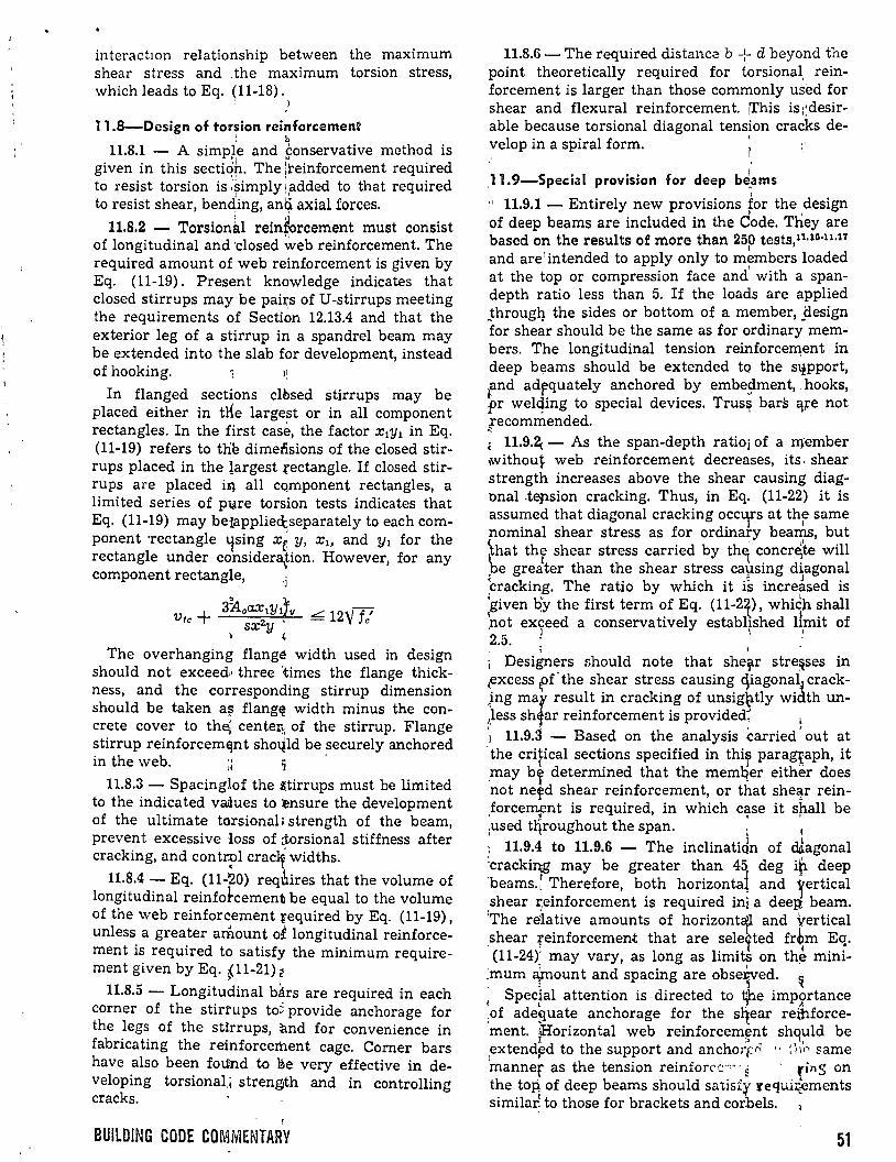
interactwn relationship between the maximum shear stress and :the maximum torsion stress, which leads to Eq. (11-18).
; J
11.8-Design of torsion reinforcement ~ b
11.8.1 - A simpte and sonservative method is given in this sectiqp. The !teinforcement required to resist torsion is :simply 1added to that required
1 '1
to resist shear, benqing, anq axial forces.
11.8.2 - Torsion~l reinforcement must consist of longitudinal and''Closed ~eb reinforcement. The required amount of web reinforcement is given by Eq. (11-19). Present knowledge indicates that closed stirrups may be pairs of U-stirrups meeting the requirements o'f Secti~n 12.13.4 and that the exterior leg of a stirrup in a spandrel beam may be extended into the slab for development, instead of hooking.
In flanged sections clbsed stirrups may be placed either in ttle largest or in all component rectangles. In the first case, the factor X¡y¡ in Eq. (11-19) refers to the dimedsions of the closed stirrups placed in the largest rectangle. If closed stirrups are placed iq all cqmponent rectangles, a limited series of p~re torsion tests indicates that Eq. (11-19) may beiapplieQ;separately to each component -rectangle lfsing x( y, X¡, and Y1 for the rectangle under considera._tion. However, for any component rectangle,
Vtc + 311o~1Ylf11 ¿ 12\' fe' sx y
~ ' The overhanging flange width used in design
should not exceed.• three 'times the flange thickness, and the corresponding stirrup dimension should be taken a~ flang~ width minus the concrete cover to th~ centel!: of the stirrup. Flange stirrup reinforcem~nt sholild be securely anchored in the web. ~¡ 1 ·
11.8.3- Spacinglof the stirrups must be limited to the indicated vaftues to :ensure the development of the ultimate torsional> strength of the beam, prevent excessive ioss of c:torsional stiffness after cracking, and cont~l crac~ widths.
11.8.4- Eq. (11-20) reqbires that the volume of longitudinal reinfotcement be equal to the volume of the web reinforcement required by Eq. (11-19), unless a greater amount of longitudinal reinforcement is required to satisfy the mínimum requirement given by Eq. ~11-21) ~
)
11.8.5 - Longitudinal bárs are required in each corner of the stirtups to~ provide anchorage for the legs of the sttrrups, and for convenience in fabricating the reinforcement cage. Comer bars have also been foúlnd to ~e very effective in developing torsional,¡ streng,th and in controlling cracks.
BUILDING CODE COMMENTARY
11.8.6 - The required distanc~ b + d beyond the point theoretically required for tqrsional, reinforcement is larger than those comrn:only used for shear and flexura} reinforcemen t. íl'his is ;:desirable because torsional diagonal tension cracks de-velop in a spiral form. ' ¡ ·
1 11.9-Special provision for deep be,ams
:, 11.9.1 - Entirely new provisions for the ,design of deep beams are included in the Code. They are 'based on the resulta of more than 25p tests,n· 10"11•11
and are'intended to apply only to m7mbers loaded at the top or compression face and with a spandepth ratio less than 5. If the loads are applied _througl). the sides or bottom of a member, _i:lesign for shear should be the same as for ordinary members. The longitudinal tension reinforcell1:ent in deep bE;!arns should be extended to the S\lpport, fnd adj:!quately anchored by embesiment, , hooks, pr welqing to special devices. Trus~ bars ~;re not ¡ecommended. ; 11.9.2¡- As the span-depth ratio¡ of a rr¡:ember ,withou~ web reinforcement decreases, its · shear strength increases above the shear causing diagonal .tepsion cracking. Thus, in Eq. (11-22) it is assumed that diagonal cracking occlfs at thr same nominal shear stress as for ordinary beams, but \hat the shear stress carried by th~ concr~te will be greiter than the shear stress ca\]sing diagonal ~racking. The ratio by which it is incre~sed is 'given b:y the first term of Eq. (11-2X), which shall pot exyeed a conservatively establ~shed 1\mit of 2.5. : 1
; Desiiners should note that shef.r stre~ses in ~xcess pf- the s~ear stre.ss causing. ~iagon~l~ crack,ing mar. result m crackmg of uns1g~tly w1dth un-less sh ar reinforcemen t is provided, l
A , '
'1 11.9.3 - Based on the analysis carried out at 'the cripical sections specified in thir para~aph, it may b~ determined that the memqer either d~es not ne~d shear reinforcement, or that she~r remforcement is required, in which case it spall be
l i ' .used tqroughout the span. , e
: 11.9.4 to 11.9.6 - The inclinatidn of dl.agonal :cracki~ may be greater than 45' deg i~ deep 'beams.~ Therefore, both horizontal and yertical shear reinforcement is required in~ a deep beam. :The relative amounts of horizont~ and vertical shear reinforcement that are selelted fr~m Eq.
1
(11-24)i may vary, as long as limits on th~ mini~mum a}nount and spacing are obse~ed. ~
SpecÍal attention is directed to 11he importance ( l _T... .A
,of adequate anchorage for the s~ear rei;hforce-·ment. ;Horizontal web reinforcemrnt shq~ld be ,extend~d to the support and anchorr-n " ! hr same 'manner aS the tenSiOn reinfOrC'C"0"' ~ • fing On the toP. of deep beams should satisf:y requi~ments similai to those for brackets and corbels.
51
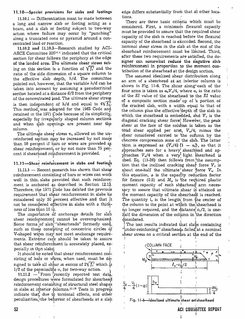
11.1 0-Special provisions for siabs and footings
11.10.1- Differentiation must be made between a long and narrow slab or footing acting as a beam, and a slab or footing subJect to two-way actwn where failure may occur by "punching" along a truncated cone or pyramid around a concentrated loador reaction.
11.10.2 and 11.10.3-Research studied by ACIASCE Committee 32611· 1 indicated that the critica! section for shear follows the periphery at the edge of the loaded aroa. The ultimate shear stress acting on this s'ection is a function of ft and the ratio of the side dimension of a square column to the effective slab depth, h/d. The committee pointed out, however, that the variable h/d can be taken into account by assuming a pseudocritical section located ata distance d/2 from the periphery of the conce~trated load. The ultimate shear stres¡? is then independent of h/d and equal to 4"V f~.
- l This method was adopted for the 1963 Code and retained m t~e 1971 Fode because of its simpli~it~, especially fo:r; irregu,larly shaped column sectwns and when sJab op)nings are present near t~e column. e <
The ul tima¡te shear stress v,. allowed on the u~reinforced sElction ~ay be increased by not morte than 50 perc;en t if ~ars or wires are provided ats shear reinfoiJ_cementx or by not more than 75 pe~.cent if shearhead reinforcement is provided.
; 1
11.11-Shea; reinfo1cement in slabs and footing~ ., (
11.11.1 - Recent ;:esearch has shown that sheél{ reinforcemel1;t consi~ting of bars or wires can wor~ well in thin, slabs provided that such reinforc~ment is anc~ored ~s described in Section 12.1~. Therefore, t~e 1971 Fode has deleted the previo~s requirement }that snear reinforcement in slabs b.e considered only 50 ~ercent effective and that it not be considered effective in slabs with a thic~-
~ t Ll
ness of less than 10 it). 1
The 1mportance df anchorage details for slab shear reinforcement. cannot be overemphasized.
t l ~ Sorne forms "of slab' "shearheads" formerly useq, such as thoJr consi~ting of concentric circles. ~~ V-shaped wir,es ma~ not meet anchorage requiremen ts. Extr~me car'e should be taken to assure
' l that shear reinforcetnent is accurately placed, es-pecially m tryn slab~( :(
It should be noted that shear reinforcement corísisting of bats or Wires, when used, must be de-signed to tak~ all shkar m excess of 2-yf( which {s 1/2 of the permissibÍe Ve for two-way action. ~
11.11.2 - ~ From ~recently reported test datf¡, design proceaures were formulated for shearhead reinforcement consi~1ting of structural steel shape~ in slabs at i~terior 1olurnns.U·18 Tests in progre~ mdicate that~ due to torsional effects, and other peculiarities,_lthe be~avior of shearheads at a slap
52
edge differs substantially frorh that at other loca-tions. .
There are three basic criteria which must be 1 1
considered. First, a mínimum flexura! capacity must be provided to assure that the required shear capacity of the slab is reached befare the flexura! capacity of the shearhead is exceeded. Second, the nominal shear stress in the slab at the end of the shearhead reinforcement must be lirhited. Third, after these two requirements are satisfied, the designer can somewhat reduc¿ the riegtltive slab reinforcement in proportion to the moment contribution of the shearhead at the design section.
The assumed idealized shear distribution along an arm of a shearhead at an interior column is shown in Fig. 11-6. The shear along- each of the four arms is taken as a.vVe/4, where avis the ratio of the El value of the shearh~ad to the El value o~ a composite section mader up of La portian of the cracked slab, with a width equ~l to that of the column plus the effective ?depth of the slab in which the shearhead is embetlded, ahd Ve is the diagonal cracking shear force~ However, the peak shear at the face of the colJmn is taken as the total shear applied per arni, Vu/4; minus the
. shear considered carried to the column by the cbncrete compression zone o{ the slab. The latter t~rm is expressed as (Vc/4) (1 - a,;), so that it approaches zero for a heavy' shearh'ead and app1roaches Vu/4 when a veryt light shearhead is dsed. Eq. (11-26) then follows from.1the assumption that the inclined cracking sheaf force Ve is about one-half the ultimate L shear force V.,. In this equation, q, is the capaclty redÜction factor fb·r flexure (0.9) and M v is ~he reqtlired plastic moment capacity of each sh~arhead1 arm neces-
l l ~.
sary to assure that ultimate shear is attained as the moment capacity of the shearhea'd is reached. ~he quantity Z,, is the lengt~. from ~he center ~f the column to the point at WliiCh the. shearhead 1s ~o longer required, and the ~istance7 ct/2, is oneHalf the dimension of the column in 1the direction e ·¿ d l , 1ons1 ere . . . , The test results indicated ~hat slajs containing
"}mder-reinforcing" shearheajs faile~at a nominal shear stress on a critica! sectron at tP¡.e end of the ! l
Vu Ve [GJ ~ -4(1-a~ j''------~----~J~c
j .:
Fig. 11-6-ldealized ultimate :shear onlshearhead j '
ACI COMMITTEE REPOFIT
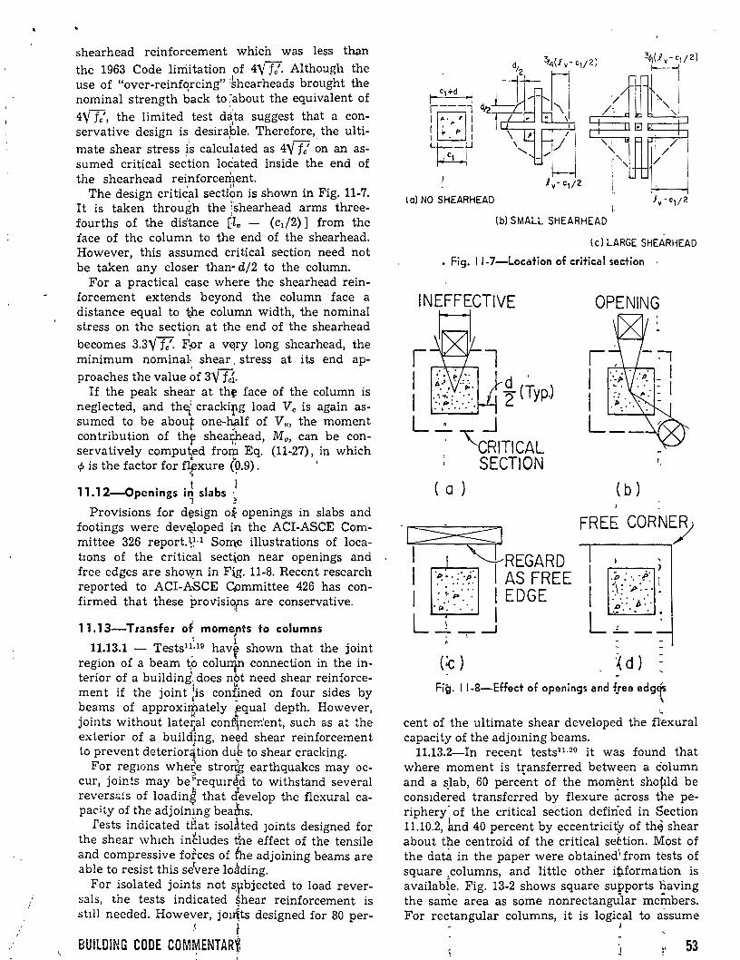
/
shearhead reinforcement which was less than the 1963 Code linütation of 4"Vf7. Although the use of "over-reinfqrcing" :khearheads brought the nominal strength back to ¡about the equivalent of
4Y fe', the limited 1
test d~ta suggest that a conserva ti ve design is, desiraple. Therefore,_ the ulti-mate shear stress is calculated as 4Y fe' on an assumed critica! sec.tion loc'ated inside the end of
1 ,.
the shearhead reinforcement. ' /1
The design critica! section is shown in Fig. 11-7. It is taken through the \'shearhead arms threefourths of the distance [lv - (c¡j2)] from the face of the column to the end of the shearhead. However, this assumed critica! section need not be taken any closer than· d/2 to the column.
For a practica! case where the shearhead reinforcement extends beyond the column face a distance equal to t-he column width, the nominal stress on the section at the end of the shearhead
l
becomes 3.3Y fe'· Fpr a vEJry long shearhead, the mínimum nominal, shear . stress at its end ap-
proaches the value ~f 3"V fcí. If the peak shear at th~ face of the column is
neglected, and the¡' crackiFg load Ve is again assumed to be about one-~lf of V"' the moment contribution of thr shea¡¡flead, Mv, can be conservatively comput¡ed frorp. Eq. (11-27), in which </> is the factor for f]ftxure (0.9) .
:;) '
11.12-0penings i~ slabs ~ Provisions for dt:sign o~ openings in slabs and
footings were devttloped in the ACI-ASCE Committee 326 report.~~· 1 Sorn.e illustrations of locatwns of the critica! section near openings and free edges are sho\'{n in F¡g. 11-8. Recent research reported to ACI-ASCE Cpmmittee 426 has confirmed that these provisiqps are conservative.
11.13-Transfer of moments to columns . , 11.13.1 - Tests1 ~_: 10 havf shown that the joint
region of a beam t.o colun¡n connection in the interior of a building. do es nbt need shear reinforcement if the joint :is confined on four sides by beams of approxin;¡.ately pqual depth. However, joints without late5al conflnement, such as at the exterior of a buildjng, ne~d shear reinforcemen t to prevent deterior~tion du~ to shear cracking.
For reg10ns where strorfg earthquakes may occur, joints may be~reqUiréd to withstand severa! revers;;¡1s of loadin~ that cfevelop the flexura! capaci~y of the adjoimng bea&s.
Tests indicated ti1at isolated JOints designed for the shear wh1ch in~ludes the effect of the tensile and compressive fofces of éh.e adjoining beams are able to resist this s.Jvere lo~ding.
For isolated joints not s.pbjected to load reversals, the tests indicated $hear reinforcement is stlll needed. However, jo1~ts designed for 80 per-
,< ~
BUILDING CODE COM~ENTARt, '
1 o) NO SHEARHEAD
,//
/-
'1
' 1·'-1 ' 1
l. (b) SMALL SHEARHEAD
kJ [!J
1/ /
1 /
(e) LARGE SHEARHEAD
• Fig. 11-7-Location of critica! section ,
~~ 1 d . 1 2 (Typ.)
L_· _j . '-cRITICAL
1
SECTION ( a )
OPENING
( b )
··¡~~~Gt:E FREE CORN~
1 : ::~ .. · 1 EDGE • 1>. • • 1
L _\ -. _ __J
(~)
Fig. 11-8-Effect of openings and fsee edgt
~
cent of the ultimate shear developed the flexura! capacity of the adjoming beams.
11.13.2-In recent tests1L 20 it was found that where moment is t~ansferred between a éolumn and a slab, 60 percent of the mom~nt shopld be cons1de~ed transferred by flexure ácross the periphery- of the critica! section defiried in Section 11.10.2, knd 40 percent by eccentricity of th~ shear about the centroid of the critica! seétion. Most of the data in the paper were obtained\ from tests of square _columns, and little other iP.formation is availabÍe. Fig. 13-2 shows square supports fiaving the sanie area as sorne nonrectangÜlar meÍnbers. For rectangular columns, it is logical to assume
J
53
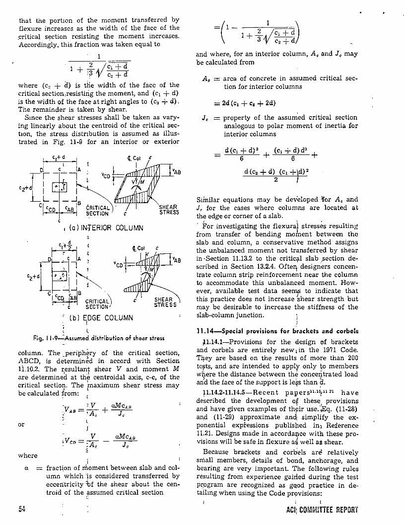
that the portwn of the moment transferred by flexure in creases as the wid th of the fa ce of the _critical section resisting the moment increases. Accordingly, this fraction was taken equal to
1
1 + ~, jc1 + d 'r 'V c2 + d
where (e~ + d) is the width of the face of the critical section,resisti#g the moment, and (e¡ + d) is the width of the face at right angles to (c2 + d). The remainder is taken by shear.
Smce the shear stresses shall be taken as varying linearly about the centroid of the critica! sectwn, the stress distnbution is assumed as illustrated in Fig. 11-9 for an interior or exterior
e e
e (a) INTERIOR COLUMN
' (b) EDGE COLUMN : t .
:,
G
SHEAR STRESS
Fig. 11-9-=Assumed distribution of shear stress
column. The _periphéry of the critical section, ABCD, is determinJd in accord with Section 1i.10.2. The resultant shear V and moment M
1 .1 are determined at the centroidal axis, c-e, of the
l
critical section. The maximum shear stress may " l be calculated from:
or
- V 1Vcn =::--A - • e
S where
1
a fract~on of rnoment between slab and col-
54
umn which 'is considered transferred by eccerftricity =bf the shear about the centroid of the .~ssumed cri ti cal section
=(1- l+~~c,+d) 3 c2 + d
and where, for an interior colulfln, A o and Jo may be calculated from
Ao = area of concrete in assumed critica! section for interior columns
= 2d(c1 +Ca+ 2d)
' Jc = property of the assumed critica! section
analogous to polar moment of inertia for interior columns
d(c1 + d) 3 + (c1 + d)d3 + 6 6
d(c2 + d)2
(c1 +)d)2
Similar equations may be developed 'ror Ac and ] 0 for the cases where columns are located at the edge or comer of a slab.
1 : •
· For investigating the flexura! stresses resulting from transfer of bending mofuent between the slab and column, a conservative method assigns the unbalanced moment not transferred by shear in -Section 11.13.2 to the critiqll slab ¡,section described in Section 13.2.4. Ofterr designers caneentrate column strip reinforcement near the column to accommodate this unbalanced moment. However, available test data seernr to indicate that this practice does not increase -shear strength but may be desirable to increase the stiffness of the slab-column junction.
11.14-Spec:ial provisions for brackets and corbels
p.l4.1-Provisions for the clesign (J>f brackets and corbels are entirely new 1 in the 1971 Code. T~ey are based on the results of more than 200 te?ts, and are intended to applf only ~o members w?ere the distance between the conce~trated load and the face of the support is le~s than d.
' p.14.2-11.14.5-Recen t pa¡¡>ers1 1.1~· 11 21 ha ve described the development of these provisions
' ·' and ha ve given examples of th~ir use. ¡Eq. (11-28) an.d (11-29) approximate and¡ simplify the exponential expressions published in1 Reference 11.21. Designs made in accorda~ce witlu. these provisions will be safe in flexure as well as shear.
Because brackets and corliels are relatively small members, details of bond, anchorage, and bearing are very important. The following rules resulting from experience gairled duri:ng the test prpgram are recognized as gctod practice in detaihng when using the Code pr9visions:
ACI1 COMMITTEE REPORT
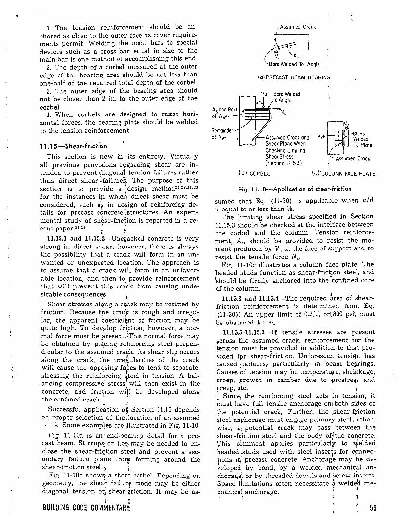
1. The tension reinforcement should be anchored as clase to the outer face as cover requirements permit. Welding the main bars to special devices such as a cross b~r equal in size to the main bar is one method of accomplishing this end.
2. The depth of a corbel measured at the outer edge of the bearing area should be not less than one-half of the required total depth of the corbel.
3. The o u ter edge of the bearing area should not be closer than 2 in. to the outer edge of the corbel.
4. When corbels are designed to resist horizontal forces, the bearing plate should be welded to the tension reinforcement.
11.1 5-Shear-friction
This section is new in, its entirety. Virtually all previous provisions r~garding shear are intended to prevent diagonal tension failures rather than direct shear ~failure~. The purpose of this section is to provide a,: design method11 22•11.
23
for the instances in which direct shear must be considered, such ¡? in depign of reinforcing d~tails for precast cqncrete ,structures. An expenmental study of sh~ar-fnc!ion is reported in a re-cent paper.U :H [ ~
11.15.1 and 11.15.2-Unqacked concrete is very strong in direct shear; however, there is always the possibility that a crack will form in an unwanted or unexpected location. The approach is to assume that a crack will form in an unfavorable location, and then to provide reinforcement that will prevent this crack from causing unde-sirable consequences.
1
' · Shear stresses alQng a Cl{.ack may be resisted by friction. Because tpe crack is rough and irregular, the apparent coeffici~nt of friction may be quite h1gh. To deJ.elop fri.ction, however, a normal force must be ¡:¡resent~This normal force may be obtained by pl~cing re!nforcing steel perpendicular to the assurped crack. As shear slip occurs along the crack, t~e irretularities of the crack will cause the opp~sing fa1~es to tend to separate, stressing the reinf~rcing 1teel in tension. A balancing compressive stress· will then exist in the
1 ,.
concrete, and fnctwn wiJI be developed along the confmed crack._ . ..
Successful applic{l tion o~ Sect10n 11.15 depends on proper selection of the ,location of an assumed
.::< Sorne examp!es are ~llustrated in F1g. 11-10.
F1g. ll-10a 1s an: end-bearing detail for a precast beam. St1rrups_, or tie~ may be needed to endose the shear-fri~tion st~el and prevent a secondary fallure plape fro~ forming around the shear-friction steel. ':! ¡
F1g. 11-10b show&¡ a shor:t corbel. Depending on geometry, the shear fa¡lu~~ mode may be either diagonal tension or; shear-friction. It may be as-
~ " BUILDING COOE COMMENTAR'i<
Rema:nder qf Avf
(al PRECAST BEAM BEARING
~ Bars Welded la Angle
~-+Nu
Assumed Crack and Shear Plane When Check:ng L:m:t:ng Sheor S lress (Sect:on 1115 3)
·(b) CORBEL
A Studs vf Welded
To Piafe
Assumed Crack
( C) ·cot.U MN FACE PLATE
Fig. 11-1 0-Application of shear~friction
sumed that Eq. (11-30) is applicable when a/d is equal to or less than 112.
The limiting shear stress specifi~d in Section 11.15.3 should be checked at the inteJ:face between the corbel and the column. Tens'ion reinforcemen t, A., should be provided to r,esist the moment produced by V,. at the face of support and to resist the tensile force N,..
Fig. 11-10c illustrates a column face plate. The headed- studs function as shear-friction steE!l, and 1~hould be firmly anchored into the -confined core of the column.
11.15.3 and 11.15.4-The required ~rea of .-shearfriction reinforcement is determined from Eq. (11-30): An upper limit of 0.2fc', ort800 psi', must be observed for v,.
11.15.5-11.15.7-If tensile stresses· are present across the assumed crack, reinforc~ment f.or the ~enswn must be provided in addition to that pro~ided fpr shear-friction. Unforesee~ tensiGn has caused ,failures,. particularly in beam be!lrings. Causes ~f tension may be temperatUji'e, shri¡nkage, ~reep, growth in camber due to prestre:¡s and ~reep, ~te.
1. S m ce¡ the reinforcing steel acts in tension, i t must h~ve full tensile anchorage on¡ both siiies of the potential crack, Further, the .shear-f~iction ~teel an¡::horage must engage primary steel;·otherwise, a, potential crack may pass between the shear-ftiction steel and the body of~ the concrete. 'rhis cómment applies particularlr to ~elded headed .studs used with steel inserts for connec-
L 1
pons ~~· precast concrete. Anchorage may be de-veloped by bond, by a welded mechanical anchorage1 or by threaded dowels and ;screw ihserts. Space ltmitations often necessitate a weldetl me-¿hamcal anchorage. 1 1
55
11.16-Spccial prov1s1ons for shear walls
11.16.1-Horizontal shear in the plane of a wall, as a design! consideration, is primarily of importance. for l~w shear walls. The design of higher walls, particularly those with uniformly distributed reinforcement, will probably be controlled by flexural considerations. It is, therefore, essential• that the flexúral capacity of shear walls be computed, along with their shear capacity.
11.16.2 - The "talues of Ve computed from ~q. (11-32) and (11-33) at a section located a distance l .. /2 or h,j2 (whichever is less) above the base apply to that and all sections between this section and the base. The maximum Vu at any section, including the base of the wall, shall not exceed the value given in Section 11.16.5.
11.16.3 - Eq. (11-32) and (11-33) predict the inclined crf-cking ~trength at any section through a shear wall. Eq. (11-32) corresponds to the occurrence of a priricipal tensile stress of apprdxi-
- ~ e mately 4Vfc' at tne centroid of the shear wall
e o d 1 . cross section. Eq. (11-33) correspon s approxl-mately to 1 the occurrence of a flexural ten~ile
,_ l '
stress of 6Y fe' at ¡¡. section l,c/2 above the section being inve~tigatedr -
11.16.4 ~ Sufficient horizontal shear reinforce-" J
ment is r~quired; to carry the shear stress r:ex-ceeding vg,. Addi~ional vertical reinforcemen~ is required, l¡>ecause ;test data indicate that unifo¡mly distribqted lollj5itudinal reinforcement as v.-rell as transv~rse sh~ar reinforcement is neede~ in
. low shear fValls. :? ~ 11.16.5 1 Although the width-to-depth ratio of
shear walfs is less than that for ordinary be~ms, recent tests on s~ar walls with a thickness equal to l,c/25 ha,Ye inditated that ultimate shear stresses up to 12V fe' can be obtained. However, the design shear stress v" is.'limited by the Code to a v~lue of 10\' fe'.'; ::;
References
11.1. ACI-ASCE --Commtttee 326, "Shear and Diagonal Tension," ACi JouRNAL, Proceedings V. 59, No. 1, Jan. 1962, pp. 1-30; No. 2, Feb. 1962, pp. 277-334; 1 and No. 3, Mar.' 1962, p~. 352-396. Also, ACI Manual of foncrete Practice, ParL2, 1968.
11.2. BreSler, B., <and MacGregor, J. G., "RevieJ.v of Concrete Beams F~iling in Shear," Proceedings, A'SCE, V. 93, ST1,~Feb. 196ff, pp. 343-372. ~
11.3. M<\fGregor,: James G., and Hanson, Joh~ M., "Proposed ~ Change~1 in Shear Provisions for Reinferced and Pres~ressed Concrete Beams," ACI JouRNAL, Proceedings V. 66, No. 4, Apr. 1969, pp. 276-288. 1
11.4. Jmht Com¡pittee, "Recommended Practicél and Standard Speciftcation for Concrete and Reinforced Concrete,"j¿ Procee~ings, ASCE, V. 66, No. 6, P,rt 2, June 1940. '
11.5. Hogr.estad, lE.; Elstner, R. C.; and Hanson, ff. A., "Shear Strength ~f Reinforced Structural Light~eight Aggregate Concrete Slabs," ACI JouRNAL, Proceed-mgs V. 61, No. 6, Júne 1964, pp. 643-656. '
! ~\
56
' 11.6. Ivey, D. L., ar.d Buth, E., "::lhear Cap<il:HY o.:: Lightwetght Concrete Beams," ACI JoURNAL, Proceedings V. 64, No. 10, Oct. 1967, pp. 634-643.
11.7. Kant, G. N. J., "Basic facts Concerning Shear Failure," ACI JOURNAL, Proceedin.gs V. 63, No. 6, June 1966, pp. 675-692.
11.8. Diaz de Cossio, R., and Loera, S., Discussion of "Basic Facts Concerning Shear Failure" by G. N. J. Kani, ACI JouRNAL, Proceedings V. 63, No. 12, Dec. 1966, pp. 1511-1514.
11.9. Kani, G. N. J., "How Safe Are Our Large Reinforced Concrete Beams?," ACI JoURNAL, Proceedings V. 64, No. 3, Mar. 1967, pp. 128-l41.
11.10. MncGregor, James G., Discussion· of "How Snfo Are Our Large Reinforced Concrete Beams?" by G. N. J. Kani, ACI JOURNAL, Proceedings V. 64, No. 9, Sept. 1967, pp. 603-604.
11.11. ACI Committee 438, "Tentative Recommendatwns for the Destgn of Reinfórced Concrete Members to Resist Torsion," ACI JOURNAL, Proceedings V. 66, No. 1, Jan. 1969, pp. 1-8.
11.12. Hsu, T. T. C., and Kemp, E. L.:: "Tentative Dcsign Criteria for Torsion," ACI JoURNAL, Proceedings V. 66, No. 1, Jan. 1969, pp. 12-233
11.13. Mattock, A. H., "HowE to Deshgn for Torsion," Torsion of Structura! Concreta, SP-18, American Concrete Institute, Detroit, 1968, pp. 469-495.
11.14. Hsu, T. T. C., "Torsion of StrJ,lctural Concrete -Behavior of Reinforced Co~rete R~tangular Members," Torsion of Structural Concrete; SP-18, American Concrete Institute, Detroit, 1968, pp. 261-306. Also, Development Department BuHetin D135, Portland Ce-ment Association. J J
11.15. Cohen, Edward; Crist, Robert A.; dePaiv<-•. H. A. R.; Mathey, Robert G.; :O'Donne¡ll, Keith O.; and Sbarounis, J. A., "Shear Design for Bnackets and Deep Beams," presented at the 20th Fall Meeting, American Concrete Institute, Des Moines, Iowa, Nov. 1967.
11.16. dePaiva, H. A. R., an'd Siess, ~C. P., "Strenglh and Behavior of Deep Beams in Sheflr," Proceedings. ASCE, V. 91, ST5, Part 1, Oct. 1965, pp.>19-41.
11.17. Crist, R. A., "Shear Behavior of Deep Reinforced Concrete Beams," Proceedings, Symposium on the Effects of Repeated Loadiijg of Mé\terials and Structural Elements (Mexico City, l966), V. 4, RILEM, Paris, 31 pp. (Published by Inst~tuto M~xicano del Cemento y del Concreto, Mexico D. F. Mexico.)
11.18. Corley, W. G., and lfawkins, N. M., "Shearhead Reinforcement for Slabsr" ACI JpuRNAL, Proceedings V. 65, No. 10, Oct. 1968, pp¡. 811-82-t.
11.19. Hanson, N. W., and (Conner,;; H. W., "Seismk Resistance of Reinforced ., Concrete Beam-Column Joints," Proceedings, ASCE, 'W. 93, S:r5, Oct. 1967, pp. 533-560. Also, Development Department BuHetin D121, Portland Cement Association. ~ ~J
11.20. Hanson, N. W., and manson, J. M., "Shear anr.; Moment Transfer Between Concrete' Slabs and Columns," Journa!, PCA Research and Development Laboralories, V. 10, No. 1, Jan. 1968, pp. 2-16. Also, Development Department BuHetiTh D129, •Portland Cement Association. '1
11.21. Kriz, L. B., and Raths, C. Hl, "Connections in Precast Concrete Structures-Strength of Corbels," Journal, Prestressed Concrete Institt,lte, V. 10, No. 1, Feb. 1965, pp. 16-47. l ~
11.22. Birkeland, P. W., and. Birkeland, H. W., "Connections in Precast Concrete[ Constr~tion," ACI JouRNAL, Proceedings V. 63, No. 3p Mar. 19:66, pp. 345-368.
11.23. Mast, R. F., "Auxiliáry Reinlforcement in Precast Concrete Connections," f'roceedivtgs, ASCE, V. 94, ST6, June 1968, pp. 1485-1504.1< i
ACI cqMrfiiTTEE REPORT
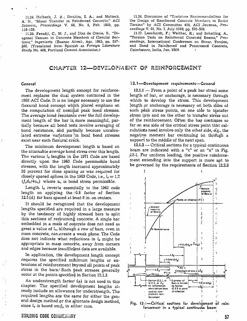
•
11.24. Hofbeck, J. A.; Ibrahim, l. A.; and Mattock, A.· H., "Shear Transfer in Reinforced Concrete," ACI JoúRNAL, Proceedings V. 66, No. 2, Feb. 1969, pp. 119-128. · 11.25. Faradji, C., M. J., and Diaz de Cossio, R., "Diagonal Tens1on in Concrete Members of Circular Sections," Ingenieria (Buenos Aires), Apr. 1965, pp. 257-280. (Translated from· Spanish as Foreign. Literature Study No. 466, Portland Cement Association.)
General
The development lengtli concept for reinforcement replaces the dual system contained in the 1963 ACI Code. It is no longer necessary to use the flexural bond concept wh1ch placed emphasis on the computation of nomipal peak bond stresses. The average bond fesistance over the full developmen t length of the bar iS¡ more meaningful, partially because all bond tes'ts involve averaging of bond resistance, ahd partially because uncalculated extreme vatlations ¡in local bond stresses exist near each fle:iural cdck.
The minimum development length is based on the attainable average bond stress over this length. The various Zd lengths in the 1971 Code are based directly upon the 1963 Code permissible bond stresses, with the length increased approximately 20 percent for close spacing as was required for closely spaced splices in the 1963 Code, i.e., Zd = 1.2 (f11db/4uu) where u .. is bo~d stress permissible.
Length Zd reverts essentially to the 1963 code length on applying the i 0.8 factor of Section 12.5 (d) for bars spaced at least 6 in. on centers.
It should be reéognized that the development lengths specified ate required in a large measure by the tendency o'f highly stressed bars to spli t thin sections of res'training concrete. A single bar embedded in a ma~s of concrete does not need as
1
great a value of ld, although a row of bars, even in mass concrete, can tereate a weak plane. The Code does not indicate what reductions in Zd might be appropriate in mas,s concréte, away from corners and edges because insufficü:!nt data are available.
In application, tHe deveiopment length concept requires the specified mihimum lengths or extensions of reinforcément b'eyond all points of peak stress in the bars.L Such peak stresses generally occur a t the poin ts ~pecifie~ in Section 12.1.3.
An understrength factori (ct>) is not used in this chapter. The specified development lengths already include an allowancEt for understrength. The required lengths ar¡e the s~me for either the general design method .9r the ~ternate design method, since zd is based on:·ifv in er~her case.
BUILDING CODE COMr~E:fiJ~RY
11.26. Discussion of "Tentabve Rccommcndations :for the Design of Remforced Concrete Membcrs to Rcsist Torsion" by ACI Commlttee 438, ACI ,JOURNAL, Pro-ceedings V. 66, No. 7, July 1969, pp. 576-588. ,
11.27. Leonhardt, F.; Walther, R.; and Schelling, A., "Torsion Tests on Reinforced Concrete Beams," Proceedings, International Conference on 'shear, Torsion, and Bond in Reinforced and Prestressed Concrete, Coimbatore, India, Jan. 1969.
12.1-Development requiremenrs-Ccneral
12.1.1- From a point of a peak bar stress sorne length of bar, or anchorage, is necessary through which to develop the stress. This development length pr anchorage is necessary on both sfdes of such p~ak stress points, on one sicle to ttansfer ~tress ipto and on the other to tran~fer stress out of the reinforcemen t. Often the ba~ con tiruxes so far on one side of the critica! stress point that calculations need involve only the other side, ~g., the nega~iv~ moment bar continuing on thrdugh a support to the middle of the next span.
12.1.3- Critical sections for a typical continuous beam are indicated with a "e" or an "x'' in Fig.
1-il2-1. Fqr uniform loading, the positive reinforcement extending into the support is more apt to be governed by the requirements of Section 12.2.3
!
used os com· press•on reanforcement
1 .,
1 -le •
e ' >l{orl2db) :
>R¡j-...1
,¡
fig. 12-1-Critical sections for develo¡pment ~f reinf~rcement ·in a typical continuoLs beam·
57
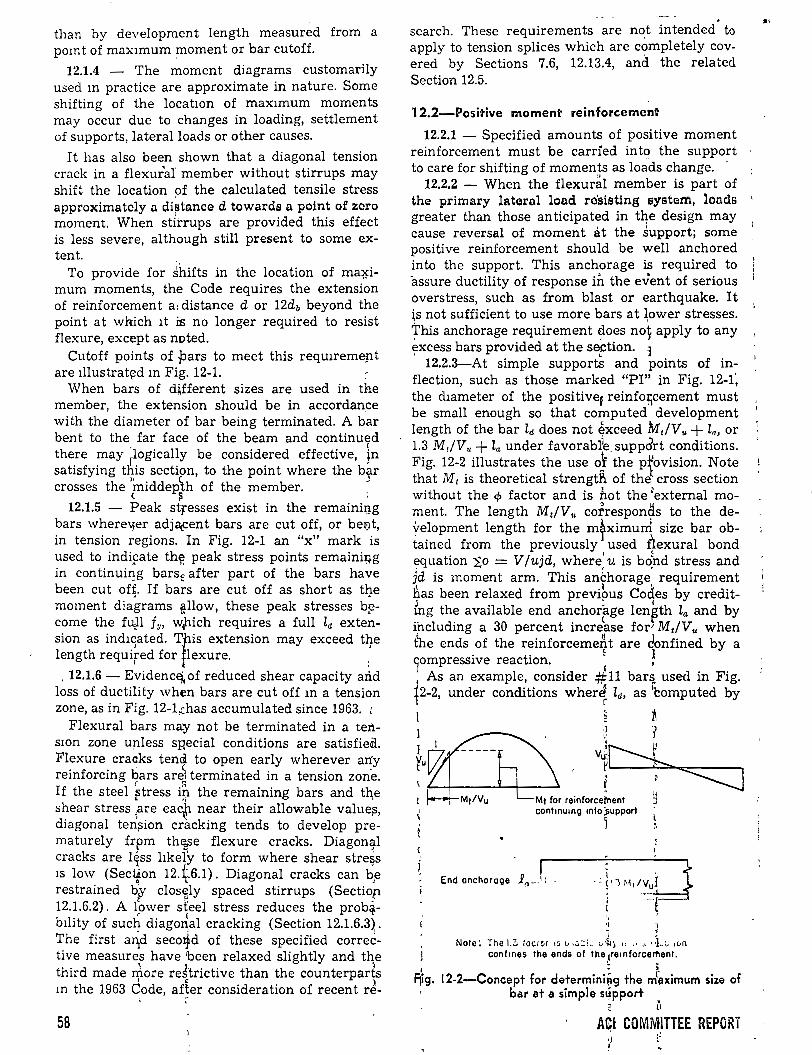
than by development length measured from a pomt of max1mum ;moment or bar cutoff.
12.1.4 - The moment diagrams customarily used m practice are approximate in nature. Sorne shifting of the locatwn of max1mum moments may occur due to changes in loading, settlement of supports,.lateralloads or other causes.
It has also been shown that a diagonal tension crack in a flexura.!' member without stirrups may shift the location of the calculated tensile stress approximatcly a di~tance d towards n point of 2:oro moment. When stÍrrups are provided this effect is less severe, although still present to sorne ex-tent. .
To provide for shifts in the location of ma~imum moments, the Code requires the extension of reinforcement a: distance d or 12db beyond the point at which lt iE no longer required to resist flexure, except as noted.
Cutoff points of pars to meet this reqUiremep.t are lllustrat¡:!d m Fig. 12-1.
When bars of d~fferent sizes are used in the member, the extension should be in accordan.ce with the diameter of bar being terminated. A bar bent to the far face of the beam and continll(rd there may 'logically be considered effective, }n satisfying tl\is section, to the point where the b~r crosses the
1middeplh of the member. : ( ~ .
12.1.5 Peak stresses exist in the remainigg bars where\¡er adjé\Cent bars are cut off, or beQ.t, in tension ~egions. In Fig. 12-1 an "x" mark is used to indifate th~ peak stress points remaini~g in continui~g barse after part of the bars have been cut off. If bars are cut off as short as tl¡.e moment diagrams e.llow, these peak stresses b~come the fuJ.l fv, w¡llich requires a full ld extension as ind1sated. Ttis extension may exceed tl}e length required for lexure. .
f '
. 12.1.6 - E~idenc~ of reduced shear capacity and loss of ductility when bars are cut off m a tension zone, as in Fig. 12-1,~has accumulated since 1963. ;
Flexural bars may not be terminated in a tenswn zone upless sp,ecial conditions are satisfiedi. Flexure craaks tenci to open early wherever any reinforcing l:)ars areJ terminated in a tension zone. If the steel ~tress i~ the remaining bars and th,e shear stress
1.are ea'f near their allowable value~,
diagonal ten~ion cracking tends to develop prematurely frpm thEESe flexure cracks. Diagon~l
cracks are l~ss hkely to form where shear stre9s 1s low (Sect¡on 12.~6.1). Diagonal cracks can b,e restrained b~Y closely spaced stirrups (Sectiop
t o • 12.1.6.2). A l~nver st'eel stress reduces the prob~-bility of such diago~al cracking (Section 12.1.6.3),. The first aqd seco4d of these specified corrective measures have 'been relaxed slightly and tqe third made rriore re~'trictive than the counterparts
1 ~ )
m the 1963 Code, af~er consideration of recent re-
58
' search. These requirements are not intended to apply to tension splices which are completely covered by Sections 7.6, 12.13.4, and the related Section 12.5.
12.2-Positive moment reinforcement
12.2.1 - Specified amounts of positive moment reinforcement must be carried int9 the support tocare for shifting of moments as loads change. ·
12.2.2 - When the flexur~l member is part of the primary lateral lond ro'sisting system, londs greater than those anticipated in tqe design may cause reversal of moment at the support; sorne positive reinforcement should be well anchored into the support. This anch.orage is required to "assure ductility of response in the event of serious overstress, su eh as from blast or earthquake. I t is not sufficient to use more bars at ~ower stresses. This anchorage requirement ~oes no~ apply to any excess bars provided at the SEftion. J ' 12.2.3-At simple supports and points of inflection, such as those marked "PI" in Fig. 12-1; the d1ameter of the positivef reinfo;cement must be small enough so that computed development length of the bar ld does not ~xceed Mt!Vu +la, or 1.3 M,/V .. +la under favorabl1e. suppart conditions. Fig. 12-2 illustrates the use o! the p}ovision. N?te that M 1 is theoretical strengtfi of the cross sectwn without the cp factor and is b.ot the 1external moment. The length Mt!V .. cotrespon~s to the de~elopment length for the mfximurri size bar obtained from the previously used 4exural bond equation !O = V jujd, where' u is bo~nd stress and ]d is moment arm. This an~horage requirement has been relaxed from previ~>Us Cocles by creditkg the available end anchorfge len~th la and by ihcluding a 30 percent increase for~ Mt!Vu when t~e ends of the reinforceme:r\t are donfined by a
. ~ 1 )Ompressive reactwn.
1 , • •
As an example, consider #11 bars usecl m F1g . ~2-2 under conditions wherJ ld, as rcomputed by t ' r
' F¡ig.
~ 8 i
v~t':::L ¡ ~~ ' 11 Mt for reinforcei'nent J
cont•numo mto };upport
J
End anchorac;¡e .R0
_ _1¡
j • Norc: The 1.3 :acror 1s tJ,.:.::L~ v~~~ 11 •• ~~ J}} .. l. ,c..n
conf.nes the ends of the te•nforcernent. . ;
12-2-Coneept for determini~g the mr~ximum size of bar at a simple sl!ípport
r\ ACI COMMITTEE REPORi
• LJ ¡J
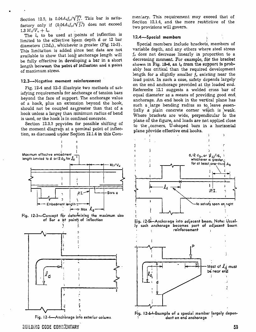
• Section 12.5, is 0.04Abf v/Y fo'· This bar is satisfactory only if (O.,Q4AdvlY fe') does not exceed 1.3 Mt/Vu + la• 1
The la to be used at ipoints of inflection is limited to the effE:ictive b~am depth d or 12 bar diameters (12db), Jhichev~r is greater (Fig. 12-3). This limitation is added since test data are not available to show that Ion~ anchorage length will be fully effective in developing a bar in a short lonsth botwsan tho poifit t# h1flgation tmd l1 point of maximum stress.
12.3-Negative moment reinforcement
Fig. 12-4 and 12-5 illustrate two methods of satisfying requirements for anchorage of tension bars beyond the face of support. The anchorage value of a hook, plus an extensi9n beyond the hook, should not be COUl;!ted as wreater than that OÍ a hook unless a largef than minimum radius of bend is used, or the hook ls in confined concrete.
Section 12.3.3 prqvides for possible shifting of t~e mom~nt diagra~ at a ztominal point of inflectlon, as d1scussed uryder Se~tion 12.1.4 in this Com-
Mox1mum effect1ve emb~dment lenglh lim1ted lo d or 12 db for } 0
1
¡...---L---;.--to+-- M ti V u
:P. I. Bors o
Fig.
J \ Embedmeot length-;.--
': hMax _ed 12-3-Coocept f~r deterfnioing the maximum
of Bar a ~t poin~ of inflection
3
¡;
,. ~
e ~ __ __._ '1
Fig. 12-4-Anchbrage info exterior column
BUiLDING CODE COm.fENTARY
size
men'.ary. This requirement may exceed that of Section 12.1.4, and the more resti-ictive of the two provisions will govern.
. 12.4-Special members :. . ' 1
Special members include brackets, members of variable depth, and any others where steel stress fs does not decrease linearly in pr~portion to a decreasing moment. For example, for the bracket ahpwn in :Fiif, 12·8, afi Za :rrom the support is probably less critica! than the required development length for a slightly smaller f 8 existing near the load point. In such a case, safety depends largely on the end anchorage provided at the loaded end. Referen'ce 12.1 suggests a welded "cross bar of equal diameter as a means of providing good end. anchorage. An end hook in the vertical plane has such a large bending radius as to leave .essen-. ' ~ r tially a plain concrete corner which is weak. Where brackets are wide, perpendicular b the plane oÍ the figure, and loads are not applied clase to the ccorners, U-shaped bars in a horizontal plane provide effective end hooks.
iP.I. 1
l lo soi1Sfy spon on, nght
L
~ig. 12-~Anchorage into adjacent beam. Note: .Usually such anchorage becomes part of adjacent beam
reinforcement
M~st of id. must be. neor eru:l
J
Fi,g. 12-~Example of a special member largely depen-; ' dent on end anchorage l
59

12.5-DeveiÓpment length of deformed bars and !' ¡.
deformed wi~e in te';lsion
This section provides specific ld requirements to be u sed wi th various bar sizes and deformed wire, including modification factors for top bars, yield stress greater than 1160 ksi, lightweight concrete:, wide lateral spacing between bars, and other conditions. :.
The factors of Section 12.5 (b), 12.5 (e), and 12.5 (d) are multiplied together when more than one is applicable and provide a composite constant which is multiplied by the basic development length as obtained in Section 12.5 (a), for either bars or deformed wire. Thus for many cases the basic lct far deformed bars is given bf
0.04Abfv!Y fe' but top bars with fv greater than 60
ksi would require two special factors, as follows: 1 _· (
ld = (0.044dJV f.p') X 1.4 X (2 - 60,000/fv)
Similarly, th~ same~bars spaced at least 6 in. op centers woulCl. permft the use of a third factor: ~
ld = (0.04Abifu1Yfc"Y. X 1.4 X (2- 60,000/fv) X 0:'8 It should be 'noted that the basic ld is required to be at least 0.0004dJf11 for #11 or smaller barS, which controls only when bars are very small, u~ually less tban #B' or #6. The lengths obtainetl from Section1 12.5 (a~ are approximately 20 petcent longer tnan those of the 1963 Code to providle for clase spacings o(bars, and when multiplied by the 0.8 factor proviCled in Section 12.5 (d) for ~
· · wider spacidg, become essentially the same a's those of the 1~63 Code. ~
Fig. 12-7 shows a>typical case where alternaté long and sh9rt bar~ are used in one layer. The spacing used -in app~ying Section 12.5 (d) for Bar.s y may be talfen the same as for Bars x, since Bars y are developed in Length BC while Bars x are already developed i~ Length AB.
i ( ·¿ 12.6-Development
11ength of deformed bars ir
compression 1 _ ( f ;
The weakeping effect of flexura! tension crack¡s is not presez;¡¡t for qompression bars and usuallr end bearing l~f the 'ars on the concrete is bene-
r s '¡ --o,----;----aors y
:::~¡:::::-;r:::::""e.---.---- sors x
e +. E4 A
""'-one loyer L
1
Plan viéw
'-&rs y '-Bors x
¡
~
1
1 (
1 \.
·~
t center of spon--l
60
Fig. 12-7-Sketch to clarify meaning of ~.spacing in Section 12.5 ( d)
ficial. Therefore. shorter development lengths ha ve been specified for compression than for tension.
12.7-Development length of bundled bars
An increased development lE:mgth for individual bars is required when three or four bars are bundled together. The extra extension is needed -because the grouping makes it more difficult to mobilize resistance from the "core" between the bars.
The designer should also note Section 7.4.2 relating to the cutoff points of individual bars of the bundle and Section 7.5.3 relating to splices of bundled bars.
12.8-Standard hooks
Hook anchorage tests performed at Carnegie Mellan University12 2 have ré'inforceaJ. the belief, reflected in the 1956 and 1963 ACI Codes, that the anchorage capacity of a hook in mass concrete is typically about the same as that of a!•straight bar with the same embedment len&th. Ho_pks in structy.ral members are ,often placep relatipely clase to a,free surface where splitting(forces roughly pro-
. pprtional to the total bar pull may d~termine the hook capacity. Additional restraint~, therefore, ~ere imposed in updating the anchorage values of hooks from those in the 19p3 CodE\- When fo' = 3p00 psi is used, (1) the tensi~e stres~ was limited to 0.5f11, which is similar to that allowed for qrade 4() steel in the 1963 Code, (2) the tensile fQrce was limited in any bar to 50,000 lb, and (3) tJ:le average bond stress over the equivalent embedment length le was limited to the allowable bond stress in the 1963 Code. Table 12-1 shows t~e maximum tensile force tvhich fs considered d'eveloped by a standard hook' with l' = 3000 psi u1sing the constants for standard hoo~s, ~. of this Code. The footnotes indicate the limÚs which in-' ~ ~
TABLE 12-1-MAXIMUM TENSILE FORCE, POUNDS, DEVELOPED IN STANDARD HOOKS
FOR fe' = 3000 PSI f
·' fu= 60 ksi E fu J;; 40 ksi
' Bar Other fTop bats
Other size Top bars bars bars
13 3,250* 3,250* ' 2,170' 2,170° #,4 5,920* 5,920*
( 3,940* 3,940*
#5 9,170,*t 9,170* 1 6,110~ 6,110° #6 10,850 13,020* 1 8,680t 8,680* #.7 11,830 17,750* 11,830, 11,830* #r.8 15,580 23,370*
" 15,5801 15,580°
#,9 19,720 29,580* ' 19,720~ 19,720* E
'-10 25,040 33,390t >1 25,040f 25,040* ,11 30,760t 35,880 ' 30,76ot;t 30,760* :
#14 40,660t 40,660 40,660t¡ 40,660 1
~ 48,200'~ #18 48,200t 48,200t 48,200t
:•Tens1le stress sllghtly less than O 5/3 for f•' d: 3000 psi. 'tBond stress based on equ1va!ent developmentiCJength, 1., about
equal to or less than specif1ed m Section 1801 of ACI 318·63 for fe = 3000 PSI. '1 '
-:Total force hm!ted to !ess than 50 W¡ps for ¡.( = 3000 psi. ' - i ' 1 ~
ABI COMWf.ITTEE REPORT
..
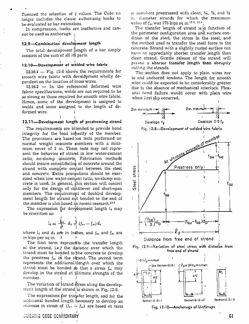
• fluenced the selection of ~ values. The Code no longer includes the claus~ authonzmg hooks to be evaluated as bar extensions.
In compression, .hooks are ineffective and cannot be used as anchorage. i\
1 •
' ll 12. 9-Combination development length
The total devel~pment ~ength of a bar simply consists of the su m 'of all i t~ parts.
1· ', 1~ L.;
12.1 0-Devolopment of w~lded wlro fabric
12.10.1 - Fig. 12.-8 sho\~S the requirements for smooth wire fabric with devel&pment wholly dependen t on the loca tion of ~ross wires.
12.10.2 - In the referenced deformed wire fabric specifications, welds are not required to be as strong as those required for smooth wire fabric. Hence, sorne of th.e development is assigned to welds and sorne assigned to the length of deformed wire.
l
12.11-Developme.nt lengt,h of prestressing strand
The requirements are irltended to provide bond integrity for the ~oad ca~acity of the member. The provisions ar~ based:)on tests performed on normal weight colílcrete members with a minimuro cover of 2 i:n. Thes~ tests may not represent the behavior of strand in low water-cement ratio, no-slump qoncretev Fabrication methods should insure cons?lidatioljl of concrete around the strand wi-th comptete coqtact between the steel and concrete. Extra prec~utions should be exercised when low wa~er-cerrlent ratio, no-slump concrete is used. In general, ~his section will control only for the desigfl of ca,ntilever and short-span members. The requiremept of doubled development length for s~rand n?t bonded to the end of the member is alsoJbased on recent research.12 3
The expression ~or dev~lopment length ld may be rewritten as: ' '
~ ll
ld = ~~e db -+i (f.,. - fsc) db ~ :) J
where ld and db are in indhes, and f., and f •• are in kips per sq in. r :e
The first term tepresei!J.ts the transfer length oi the strand, i.e.i,l the d~stance over which the s trand must be bo~ded to jthe concrete to develop the prestress fsc i~ the s~rand. 'Í'he second term represents the additiona}9length over which the str~nd must be bo.nded sp that a stress f., may dcvclop in the stránd at ~ltimate strength of the mcmber. l
The variatJon of hrand 4tress along the developmcnt length of the strand1is shown in Fig. 12-9.
1 )
The expressions for tra*fer length, and for the add!twnal bonded length hecessary to develop an 1ncrease in stress of (f,, ....:.. f,c) are based on tests
~:.J;u;:;.;~ CODE CCMMENTARY
01 mer:ü1crs prestressed with clean, %, %, and 1/2
111. dwmeter strands for wh1ch the max1mum v;1lue off,,. was 275 kips sq in.12 3 • 12·4
1
The transfer length of strand is ~a function of thc perimeter configuration area ana surface condition of the steel, the stress in the steel, and the mcthod used to transfer the steel force to thc concrete. Strand with a slightly rusted surface can have ;m appreciably shorter transfer length than clean strand. Gentle release of the strand will pot mlt ;:¡ shortcr tro.nsfot longth than abruptly cultmg the strands.
Thc section does not apply to plain wires nor to end anchored tendons. The length for smooth wirc could be expected to be considerably gréater
-due to the absence of mechanical interlock. Flex-ura! hond failure would occur with plain wire when lirst slip occurred.
l ~ 2m. mm1mum --1 ~ 'o~
Develops fy De~lops O 5 fy
' ' ' Fig. 12-8-Development of welded \vire fabfic (
)
fsu -fse
(/') only1 ~~ (/') <1)
~ l...
1 u; l·
<1) 1 1 r
<1)
\
fsu -(/) \
fse
1 t
L ~ -. V
htyh-;j..¡.c;¡ca-' --(fsu-fsel~b ~ ~ d ----:----il>f
D1stance from free end of st'rand
Fig. i 2-9-Variation of steel stress with distan~e from free end of strand
,-,
~ 1
SeciiOn 12 13 1 1 SeciiOn 12 13 L2 ~ Sec¡;on 12.13 1 3
Fig. 12-1 0-Anchorage of U-s~irrups
61
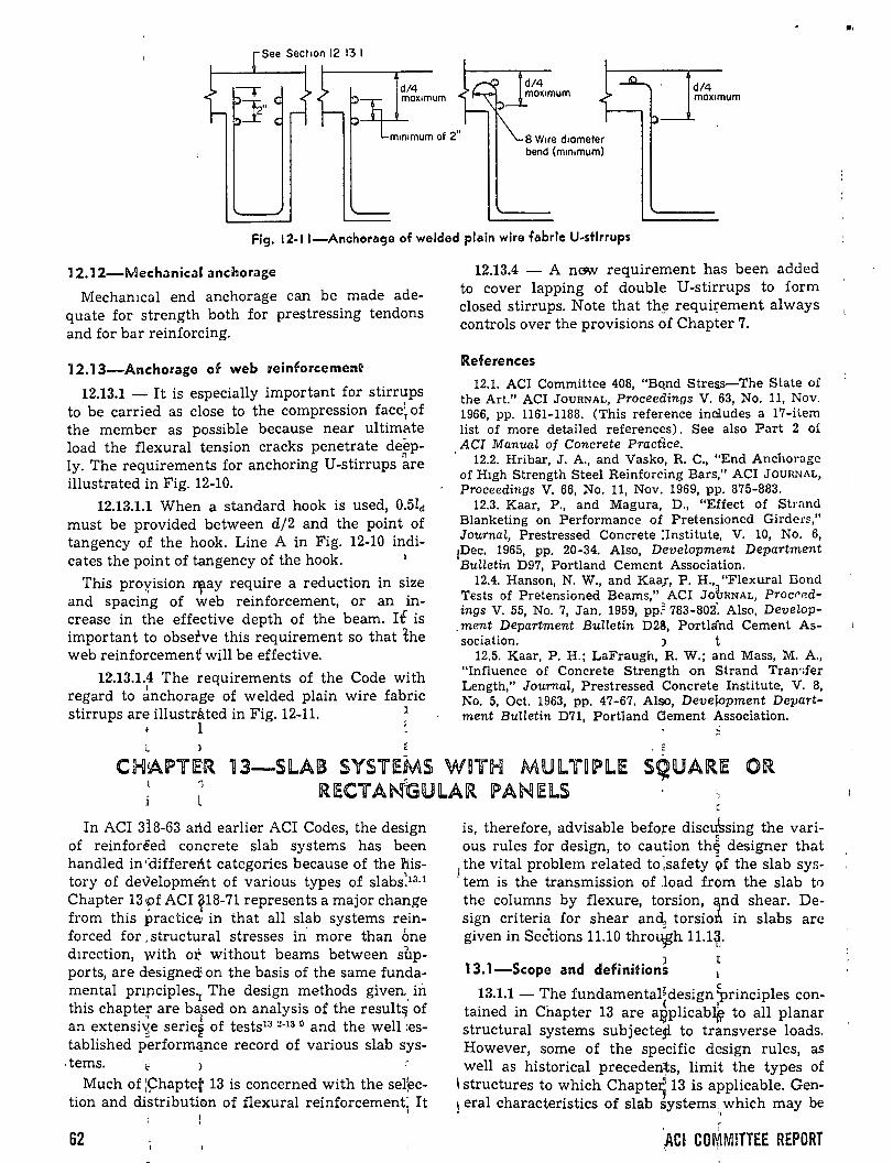
d/4 max1mum
8 W~re d1ameter bend (m1n1mum)
d/4 max1mum
Fig. 12-11-Anchorage of welded plain wire fabrlc U-stlrrups
12.12-Mechanical anchorage
Mechamcal end anchorage can be made adequate for strength both for prestressing tendons and for bar reinforcing.
12.13-Anchorage of web reinforcemen~
12.13.1 - It is especially important for stirrups to be carried as close to the compression face~ of the member as possible because near ultimate load the flexural tension cracks penetrate deep-
n ly. The requirements for anchoring U-stirrups are illustrated in Fig. 12-10.
12.13.1.1 When a standard hook is used, 0.5lct must be provided between d/2 and the point of tangency of the hook. Line A in Fig. 12-10 indi-cates the point of tangency of the hook. 1
This proxision z;¡.ay require a reduction in size and spacing of web reinforcement, or an increase in the effective depth of the beam. Ii is important to obsetve this requirement so that the web reinforcement will be effective.
12.13.1.4 The requirements of the Code with regard to ~nchorage of welded plain wire fabric stirrups are illustráted in Fig. 12-11.
l l
12.13.4 - A naw requirement has been added to cover lapping of double U-stirrups to form closed stirrups. Note that th~ requi~ement always controls over the provisions of Chapter 7.
References
12.1. ACI Committee 408, "Bqnd Stre:¡s-The State of the Art." ACI JOURNAL, Proceedings V. 63, No. 11, Nov. 1966, pp. 1161-1188. (This reference inaludes a 17-item list of more detailed references). See also Part 2 oí ,ACI ManuaL of Concrete Pract1ce. ' 12.2. Hribar, J. A., and Vasko, R. C., "End Anchorage of Htgh Strength Steel Reinforcing Bars," ACI JoURNAL,
Proceedings V. 66, No. 11, Nov. 1969, pp. 875-883. 12.3. Kaar, P., and Magura, D., "Effect of Strand
Blanketing on Performance of Pretensioned Girder~." JournaL, Prestressed Concrete :Institute, V. 10, No. 6,
¡Dec. 1965, pp. 20-34. Also, DeveLopment Department Bulletin D97, Portland Cement Association.
12.4. Hanson, N. W., and Kaa¡, P. H., "Flexura! Bond Tests of Pretensioned Beams," ACI JotrRNAL, Procf'edings V. 55, No. 7, Jan. 1959, pp.: 783-802: Also, Develop
-ment Department Bulletin D28, Portlá'nd Cement As-sociation. ) t
12.5. Kaar, P. H.; LaFraugh, R. W.; and Mass, M. A., "Influence of Concrete Strength on Strand Tran>fer Length," JournaL, Prestressed Concrete Institute, V. 8, No. 5, Oct. 1963, pp. 47-67. Also, Deve~opment Department BuHetin D71, Portland Clement Association.
~ . E
CH!APT!E~R 13-Sil..AIB SYS'frEMS W~TH MU IL T~ PliE SQ:UJARIE OR 1 RIECTA~GUlAR I?ANlElS
In ACI 318-63 arl.d earlier ACI Codes, the design of reinforeed concrete slab systems has been handled in ·<:iifferent categories because of the h.istory of developmént of various types of slabs>3·1
Chapter 13 -pf ACI ~18-71 represents a major change from this practiceJ in that all slab systems reinforced for , structu,ral stresses ii1 more than Óne direction, with ot without beams between supports, are d-esigne<! on the basis of the same fundamental pnp.ciples1 The design methods given .. in this chapte; are bafed on analysis of the result~ of an extensi~e serier of tests13 2·13 0 and the well :established performClnce record of various slab sys-
. tems. ~ ) Much of ;~haptet. 13 is concerned with the sel;ec
tion and distributi<m of flexura! reinforcement: It '
62
" is, therefore, advisable befare discJssing the vari-ous rules for design, to caution th~ designer that
1 the vital problem related to :safety Qf the slab sys
. tem is the transmission of .load from the slab to the columns by flexure, to~sion, ~nd shear. De-sign criteria for shear and~ torsion in slabs are given in Sec"tions 11.10 thro~h 11.1~.
13.1-Scope and definition~ ~ 13.1.1- The fundamental~design ~rinciples con
tained in Cnapter 13 are a~plicabl~ to all planar structural systems subjectegl to transverse loads. However, sorne of the specific design rules, as well as historical precedenls, limit the types of
\ structures to which Chapte~ 13 is applicable. Gen-1 eral characteristics of slab systems. which may be . .,
r • 1
¡AC! C01'¡1MlTTEE REPORT
"'
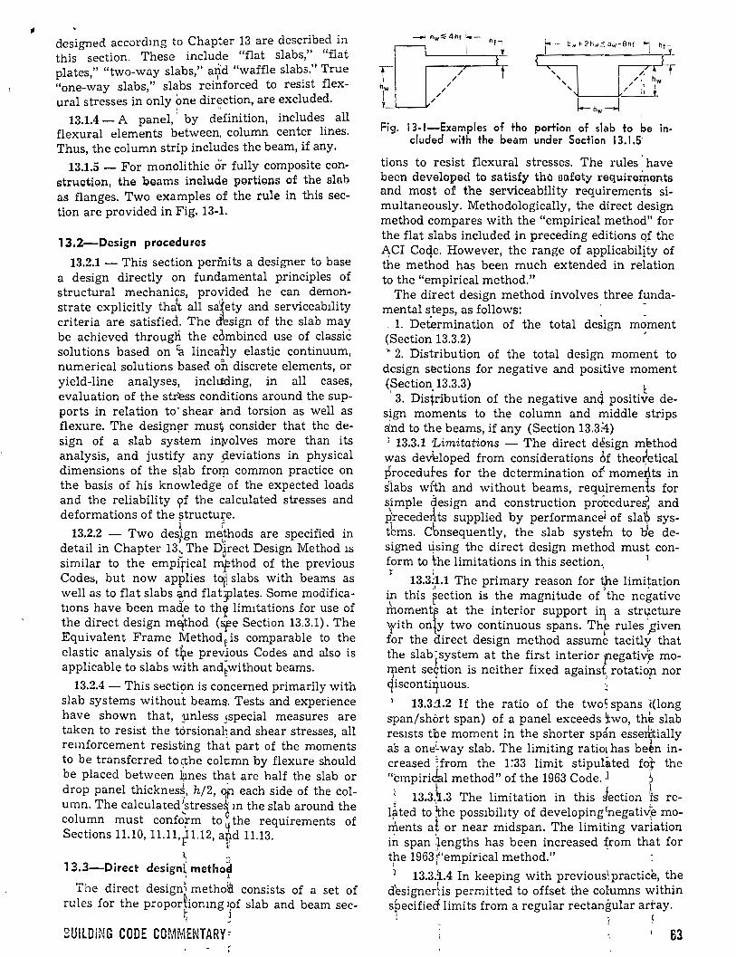
designed accordmg to Chapter 13 are described in this section. These include "flat slabs," "flat plates," "two-way slabs," a?d "waffle slab_s.'' True "one-way slabs," slabs reinforced to res1st flexura! stresses in only one direction, are excluded.
13.1.4- A panel,: by d~finition, includes all flexura! elements between, column center lines. Thus, the column strip includes the beam, if any.
13.1.5 - For monolithic o·r fully composite con· struction the beams im:lude portions of the slab
1 '
as flanges. Two examples of the rule in this sec-tion are provided in Fig. 13-1.
13.2-Design procedures
13.2.1- This section perfuits a designer to base a design directly on fundamental principies of structural mechanics, provided he can demonstrate explicitly tha~ all safety and serviceab1lity criteria are satisfied. The cPesign of the slab may be achieved througli the combined use of classié solutions based on Ca lineatly elastic continuum, numerical solutions based oh discrete elements, or yield-line analyses, incllfding, in all cases, evaluation of the str:~ss conditions around the supports in relation to· shear and torsion as well as flexure. The design~r mus9 consider that the design of a slab sys.tem in¡volves more than its analysis, and justify any sieviations in physical dimensions of the s!ab fro:q:1 common practice on the basis of his knowledge of the expected loads and the reliability 9f the calculated stresses and deformations of the structure.
13.2.2 - Two deJign m~thods are specified in ) l,
detail in Chapter 13::: The DJrect Design Method 1s similar to the empifical rnpthod of the previous Codes, but now applies to¡1 slabs with beams as well as to flat slabs ~nd flat:plates. Sorne modificatrons have been mad,e to th~ limüations for use of the direct design m~thod (spe Section 13.3.1). The Equivalent Frame Methodr is comparable to the elastic analysis of t~e prev~ous Codes and also is applicable to slabs w:ith and9without beams.
13.2.4 - This secti~n is concerned primarily with slab systems withou.t beams. Tests and experience have shown that, :J.mless ~special measures are taken to resist the tórsional~ and shear stresses, all remforcement resisting that part of the moments to be transferred to ,the colcrmn by flexure should be placed between hnes that are half the slab or drop panel thicknes~, h/2, qjn each side of the column. The calculated~stresse~ m the slab around the column must conform to Li the requirements of Sections 11.10, 11.11,~11.12, apd 11.13.
~ j 13.3-Direct designl, method
' 1
The direct design1 metho~ consists of a set of rules for the propor~ionmg 19f slab and beam sec-
~ J
BUILDING CODE COMMENTARY"
" /
" "
/ /
Fig. i 3-1-Examples of the portion of slab to be in-cluded with the beam under Section 13.1.5'
tions to resist flexura! stresses. The rules ·ha ve becn developed to satisfy tho tJafety requirements and most of the serviceability requirements simultaneously. Methodologically, the direct design method compares with the "empírica! method" for the flat slabs included in preceding editions qf the ~CI Coqe. However, the range of applicabil!ty of the method has been much extended in relation to the "empirical method."
The direct design method involves three funda-mental steps, as follows: ~ -_ l. Determination of the total design moment (Section 13.3.2) ' " 2. Distribution of the total design moment to
design sections for negative and positive moment (~ection_13.3.3) . l:
3. Distribution of the negative anq positive design moments to the column and middle strips a;nd to the beams, if any (Section 13.3~) l 13.3.1 'Limitations - The direct désign method was devieloped from considerations Oí theotetical procedures for the determination of momeÍits in s'íabs wfth and without beams, requiremenfs for simple design and construction pro:Cedurei; and p\ecedeJts supplied by performancel of slaJ:i> systkms. cbnsequently, the slab systefn to 'de designed t\sing the direct design method must con-form to the limita tions in this section., t
13.3.~1.1 The primary reason for the limitation J ' •
in this pection is the magnitude of the negative rhomentp at the interior support it'\ a strttcture 'fith onty two continuous spans. Th~ rules _$iven for the direct design method assume tacitly that the slab¡system at the first interior ¡negati~e moq¡ent se9tion is neither fixed against, rotatiop nor qisconti1fuous.
13.3.1.2 If the ratio of the two~ spans t(long span/shórt span) of a panel exceeds iwo, th~ slab res1sts the moment in the shorter spá:n essertltially as a one~way slab. The limiting ratiot has beén increased :from the 1:33 limit stipulated for the "empirickl method" of the 1963 Code. J ?
13.3.\.3 The limitation in this Jection ~s rel~ted to ~he poss1bihty of developingnegati~e moments aÍ or near midspan. The limiting variation in span jengths has been increased ~om that for the 1963;''empirical method." ' ' 1 13.3.i.4 In keeping wi th previous~ practice, the
d'esignertis permitted to offset the columns within specified limits from a regular rectangular artay.
! ~
63
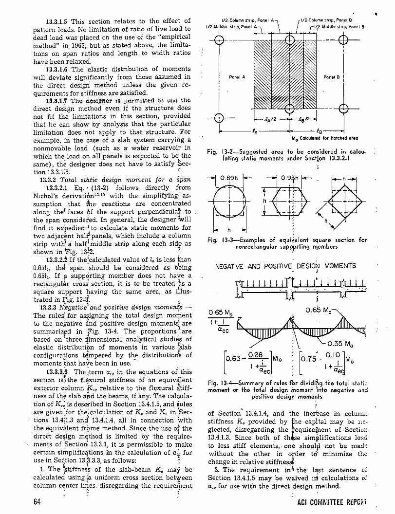
13.3.1.5 This section relates to the effect of pattern loads. No limitation of ratio of live load to dead load .was placed on the use of the "empirical method" in 1963,¡ but as stated above, the limitatwns on span ratios and length to width ratios have been relaxed.
13.3.1.6 The elastic distribution of moments will deviate signi'ficantly from those assumed in the direct' desigrt method unless the given re-quirements for stiffness are satisfied. ,
19.!J.1.7 They de;;¡¡¡ignc;,r iq pormittl';lfl t() Uát! tM direct des'ign method even if the structure does not fit the limitiüions in this section, provided that he can show by analysis that the particular limitatwn does not apply to that structure. For example, in the case of a slab system carryiñg a nonmovable load (such as a water reservoir in which the load on all panels is expected to be the same), the desigrier does not ha ve to satisfy Sec-tion 13.3.E5. e
13.3.2 Total st&tic design moment for a span 13.3.2.1 Eq. · (13-2) follows directly from
N1chol's derivation13·10 with the simplifying·: assumption that fhe reactions are concentrated along the( faces M the support perpendicular to the span considerled. In general, the designer :lwm find it expedient1 to calculate static moments for two adjadmt hal~ panels, which include a column strip w1th~ a halflmiddle strip along each sid:f as shown in Pig. 13h.
13.3.2.2 If the<calculated value of ln is less t'han 0.65l¡, the! span 'should be considered as b~ing 0.65Z1• If ¡:¡. suppó'rting member does not have a rectangul~r crosi section, it is to be treated ks a square support having the same area, as iÍlus-trated in Fig. 13-~. ~
13.3.3 rfegative1 and positive design momen{s -The rulei for assigning the total design moxpent to the negative ánd positive design moments' are summarizfd in lig. 13-4. The proportions .
1 are
based on three-dimensional analytical studies of elastic distributibn of moments in various ~slab configura!ions t~mpered by th~ distribution~~ of moments that have been in use.
13.3.3.S The .~term Ctcc in the equations oÍ this section is~ the fléxural stiffness of an equivklent exterior dolumn kcc relative to the flexura! Jtiffness of th(;i! slab avd the beams, if any. The cal~ulation of Kc; is described in Section 13.4.1.5, and nules are given'for the:calculation of Kc and K, in 'sections 13.4~1.3 an~ 13.4.1.4, all in connection Y.,ith the equiv~lent frame method. Since the use o~ the d1rect de~ign m~thod is limited by the req~irements of Section1 13.3.1, it is permissible to make certain simplific~tions in the calculation of a~ for use in Seetion 13.'3.3.3, as follows: ¡;
~ l ' l. The ¡;tiffnes~ of the slab-beam K, may be
calculated using ra uniform cross section bet».'een column c~nter liJtes, disregarding the require~ent
r ~ 64
1/2 M•ddle stnp, Panel A
t--I 1
Panel A
1~2 M•ddle stnp, Panel B
cb
Ma Calculated far hatched oreo
Fig. 13-2-Suggested area to be considerad in calculating static moments under SectÁon 13.3.2.1
Fig. 13-3-Examples of ec:¡ui~alent sc:¡uare section for nonrectangular supPfrting rf!embers
1
NEGATIVE ANO POSITIVE DESIGN MOMENTS 1
TI! 1 1 1 1 ~~u 1 1 ~; 1 1 1 u~ u í
~:~• ~ ~- 0.6_5M0~ aec ~ i~~
/ ' . o
¡0.63-028
1 JMo 1 +-
ae
Fig. 13-4-Summary of rules fbr dividihg +he total s+<•ti: moment or +he total design lnoment 'nto negativa a,,¿
positiva desig~ mome~ts
~
of Section" 13.4.1.4, and the incrl!ase in colunm sÜffness Kc provided by {he capital may be neglected, disregarding the requirefnent of Sectíon 13.4.1.3. Since both of th4.se simplificatíons lead to less stiff elements, . one shoul~ not be mad0. without the other in order to' minimize thc change in relative stiffness~
2. The requirement in~ the l~st sentence of Section 13.4.1.5 may be waived irl calculations oí Ctcc for use with the direct design method.
ACI COMMITTEE REPORT
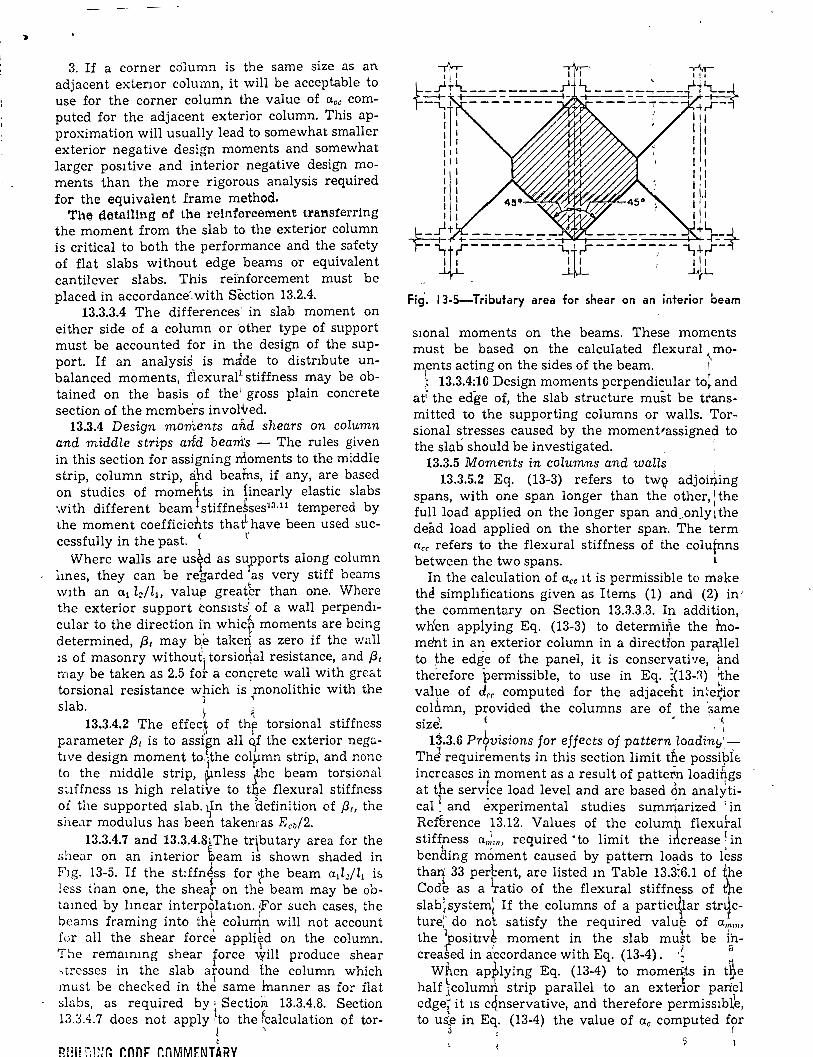
3. If a corner cólumn is the same size as an adjacent exterwr column, it will be acceptable to use for the corner column the value of a.cc computed for the adjacent exterior column. This approximation will usually lead to somewhat smaller exterior negative design moments and somewhat larger positive and interior negative design moments than the more rigorous analysis required for the equivalent frame method. Th~ dotn!Hng af the retnfareement trnnsferring
the moment from the slab to the exterior column is critica! to both the performance and the safety of flat slabs without edge, beams or equivalent cantilever slabs. This rei'nforcement must be placed in accordancé.with Section 13.2.4.
13.3.3.4 The differences' in slab moment on either side of a column or other type of support must be accounted for in the design of the support. If an analysis is m:ide to distnbute unbalanced moments, flexural1 stiffness may be obtained on the basis of the 1 gross plain concrete section of the membe"rs invol"\red.
13.3.4 Design moments and shears on column and middle strips arfd beani's - The rules given in this section for assigning rrloments to the middle strip, column strip, ahd beafns, if any, are based on studies of momehts in iinearly elastic slabs with different beam 1 stiffne&ses13 ·11 tempered by the moment coefficieb.ts that ha ve been used suc-cessfully in the past. E r
Where walls are us~d as supports alon_g c?lumn lmes, they can be regarded tas very stiff oeams wlth an a 1 Z2/l1, valu~ great,er than one. Where the exterior support cons1sts' of a wall perpendicular to the direction r_n whicr moment~ are bcing determined, {3 1 may b,e taken as zero 1f the wall ¡s of masonry without) torsio~al resistance, and f3t may be taken as 2.5 for a conc;:rete wall with great torsional resistance w!lich is ,monolithic with the slab. ; e
13.3.4.2 The effec~ of thf torsional stiffness parameter {3 1 is to assiEn all o,f the exterior nego.tive design moment to.1the colpmn strip, and nonc to the middle strip, ~nless fhe beam torsional suffness 1s high relative to tqe flexura! stiffncss oi the supported slab. ~In the Befinition of [3,, the she<1r modulus has been takemas Ecb/2.
13.3.4.7 and 13.3.4.81The tr\butary area for the she<:~r on an interior ~eam is shown shaded in F1g. 13-5. If the stiffn1ss for ~the beam a¡Z2/Zl is less than one, the shear on the beam may be obtamcd by lmear interp~latwn. {For such cases, the beams framing into th~ column will not account
1 l for all the shear force appliTd on the column. The remammg shear force \'{ill produce shear ,trcsses in the slab around the column which must be checked in thci same inanner as for flat slabs, as required by' Section 13.3.4.8. Section 13.3.4.7 does not apply ·1to the fcalculation of tor-, 1 ¡
t
BUIL8H~G CODE COMMENT~RY
Fig· .. 13-5-Tributary area for shear on an interior beam
swnal moments on the beams. These moments must be based on the calculated flexura! moments acting on the sides of the beam. l l 13.3.4;10 Design moments perpendicular to~ and
atl the edge of, the slab structure must be ttansmitted to the supporting columns or walls. Torsional stresses caused by the moment1assigned to the slab should be investigated. ;
13.3.5 Moments in columns and walls 13.3.5.2 Eq. (13-3) refers to tw\) adjoil)ing
spans, with one span longer than the other,: the full load applied on the longer span and,only t the de~d load applied on the shorter span. The term ncc refers to the flexura] stiffness of the colufnns between the two spans. L
In the calculation of a.cc It is permissible to make thE! simphfications given as Items (1) and (2) in' the commentary on Section 13.3.3.3. In addition, wh'en applying Eq. (13-3) to determi~e the hwment in a~ exterior column in a directrbn para¡llel to the edge of the panel, it is conservative, and therefore permissible, to use in Eq. :(13-:-l) ihe val1,1e of d,, computed for the adjaceht in~e~ior colnmn, pl:ovided the columns are of the ';;ame
. 1 ( ~ '( SlZe. · r
13.3.6 Prbvisions for effects of pattern load in¡,¡'-1 r . ,
The requirements in this section limit tfte possi~lé increases in moment as a result of pattern loadibgs
h ' . 1 at t e service load level and are based on analyti-cal ~ and experimental studies sumrriarized i in Refhence 13.12. Values of the columh flexural stiffness a,;"" required ·to limit the idcrease ~in
' ' 1 bentling moment caused by pattern loads to less thaJ1' 33 perl::ent, are listed m Table 13.3:6.1 of (he Code as a \-atio of the flexura! stiffness of t'he slab~system~ If the columns of a partic~lar str~cture:' do no't satisfy the required valu~ of Um,,, the ~osihv~ moment in the slab mu~t be ip-creased in a:ccordance with Eq. (13-4). ·~ ;
When ap~lying Eq. (13-4) to moments in tY,e half 1column strip parallel to an exterlor pan'el edge~ it 1s c4nservative, and therefore permissiblk, to uie in Eq. (13-4) the value of ac computed for
3 , r

the adjacent interior column, provided the col' umns are of the same size. 1:
13.4-Equivalent frame method
The equivalent frame method involves the represcntation of the.:three-dimensional slab system by a series of twd~dimensional frames which are then analyzed for¡: loads, either vertical or horizontal, acting in the plane of the frames. The momen ts so determined a t the cri tic al design sec-
1
tions of the fram'e are distributed to the slab sections in accordance with Section 13.3.3.
The equivalent framc method is '6omparable te. the "elastic analysis" for flat slaqs of previou:; ACI Codes. On tlie basis of studies reported m
- 1-' References 13.13, 13.14, andJ13.15, the equivalent .frame method has been devi~ed to P:r;:,ovide a better representation in two dimensions 10f a three-di-
1 1• 1
1 mensional system through the stratagem of de-.fining flexural stiffnesses vjhich r~flect the tor'sional rotations possible in the three-dimensional system. \:
13.4.1.1 The application of the requirements of 1 this section to a regular structure is illustrated
TABLE 13-1-MOMENT DISTRIBUTION CONSTANTS* /_,.,-.,..-m - ------
-¡ e 1 A t'r.--r-....-o-r-T-r-f--r-..-r--r-r-r-r-.-
1 125h, 1
l-i¡/6-~-
J~.- -- -·-
~ 2
---- - ~
1• Column Uniform load Stiffness Carryover1 climension FEM = Coef. ('lfl2h2) factort factor v
!. t:IA CID '] t
;r1 -y;- MAn .M(BA kAn k nA COFAB COFnA
( 0.00 0.083 o:o83 4.00 4.00 0.500 6>.500 n 0.05 0.083 0.084 4.01 4.04 0.504 ~.500
0.10 0.082 0.086 4.03 4.15 0.513 .499 0.00 0.15 0.081 0.089 4.07 4.32 0.528 0.498
0.20 0.079 0.093 4.12 4.56 0.548 0.495 0.25 0.077 0.097 ;4.18 4.88 0.573 0.491 0.30 0.075 0.102 -4.25 5.28 0.603 8.485 0.35 0.073 0.107 4.33 5.78 0.638 0.478
0.05 0.084 0.~84 ¡ 4.05 4.05 0.503 0.503 0.10 0.083 0.·86 4.07 4.15 0.513 0.503 0.15 0.081 0.089 ·4.11 4.33 0.528 0.501
0.05 0.20 0.080 0.092 . 4.16 4.58 0.548 ~.499 0.25 -- 0.078 0.096 4.22 4.89 0.573 .494
- 0.30 0.076 0.101 4.29 5.30 0.603 0.489 ' 0.35 0.074 0.107 ,, 4.37 5.80 0.638 0.481 -
0.10 0.085 0.085 4.18 4.18 0.513 0,.513 1 0.15 0.083 O.Ó88 4.22 4.36 0.528 0.511 0.10 0.20 0.082 O.Q91 -4.27 4.61 o 0.548 0.508
0.25 0.080 0.()95 -4.34 4.93 0.573 ().504 0.30 0.078 oJo o 4.41 5.34 0.602 0,.498 0.35 0.075 O.M5 4.50 5.85 0.637 0.491
j 0.15 0.086 0.086 4.40 4.40 0.526 &.526
0.15 0.20 0.084 0.~90 4.46 4.65 0.546 0.523 0.25 0.083
Or4 ·4.53 4.98 0.571 g.519
0.30 0.080 o. 99 4.61 5.40 0.601 .513 " 0.35 0.078 o. 04 4.70 5.92 0.635 Q.505
J -, 0.20 0.088 M88 4.72 4.72 0.543 0.543 0.20 0.25 0.086 0.~92 4.79 5.05. 0.568 0.539
0.30 0.083· o.M7 ~4.88 5.48 0.597 6.532 0.35 0.081 0.1102 4.99 6.01 0.632 6.524
] l 0.25 0.090 0.090 ,5.14 5.14 0.563 0.563
0.25 0.30 0.088 0.0:95 15.24 5.58 0.592 01.556 0.35 0.085 o.roo [5.36 6.12 0.626 01.548
0¡30 0.30 G )
0.092 O.Q92 ·5.69 5.69 0.585 ~585 0.35 0.090 O.Q:97 5.83 6.26 0.619 0)576
0.35 0.35 0.095 o.$5 6.42 6.42 0.609 ~609 . Appllcable when Ct/h - co/1•. For other relatlonshlps between these ratlos, thel con· stants wlll be slJghtly In error. U
' o l z,h,• 1
Z·h•• tS~~ífness is, KAn= kAnE 'i2i;, and K8 · = k8AE: i211 .
1
66 ) o
ABI COMMITTEE REPORT
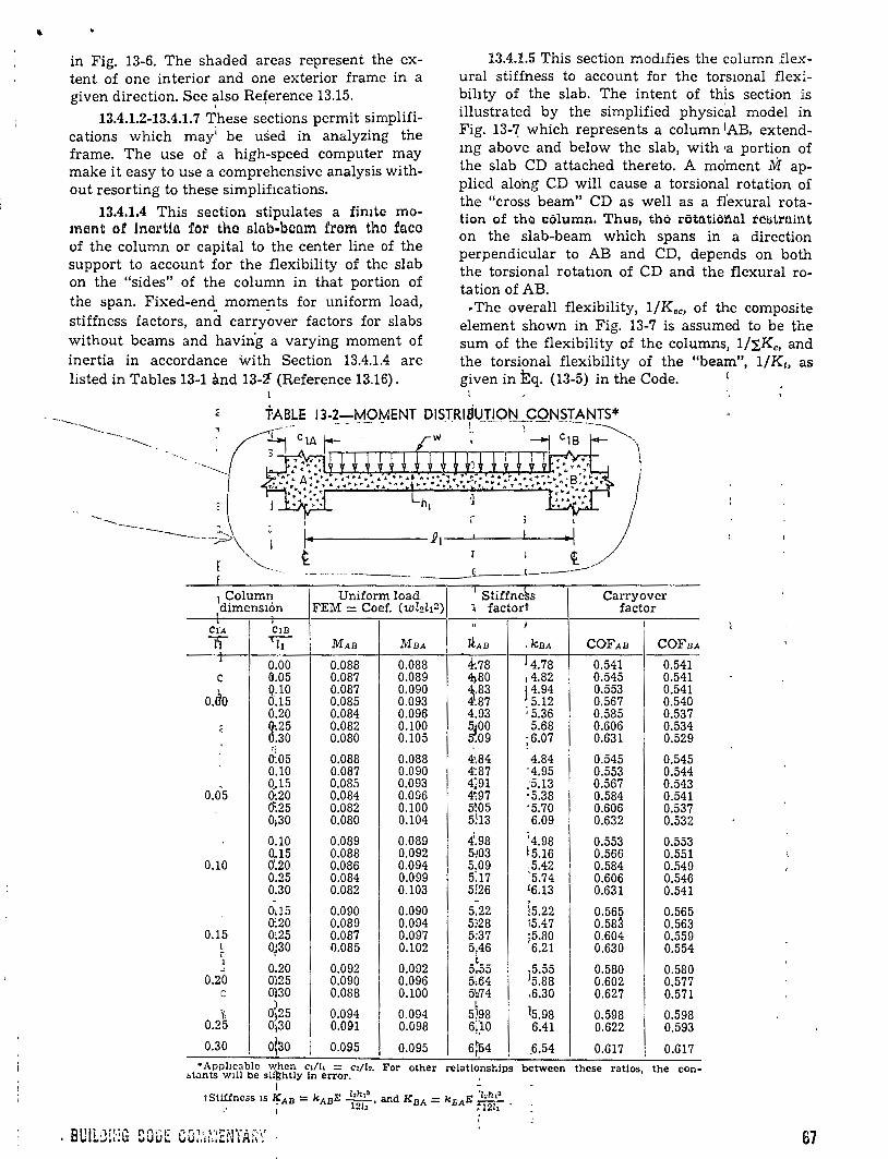
in Fig. 13-6. The shaded areas represent the cxtent of one interior and one exterior frame in a given direction. See ~lso Reference 13.15.
13.4.1.2-13.4.1.7 These sections permit simplifications which mayÍ be used in analyzing the frame. The use of a high-speed computer may make it easy to use a comprehensive analysis without resorting to these simpliflcations.
13.4.1.4 This section stipulates a fimte momcm t ot ine;u·tin for the slnb-boam írom the fa ce of the column or capital to the center line of the support to account for the flexibility of the slab on the "sides" of the column in that portian of the span. Fixed-end_ momepts for uniform load, stiffness factors, and carryover factors for slabs without beams and havin'g a varying moment of inertia in accordance with Section 13.4.1.4 are listed in Tables 13-1 and 13-~ (Reference 13.16).
13.4.1.5 This section modlfies the column .flexura! stiffness to account for the torswnal flex~
bihty of the slab. The intent of th1s section is illustrated by the simplified physic'al model in Fig. 13-~ which represents a column IAB. extendmg above and below the slab, with •a portian of the slab CD attached thereto. A moment M applied alohg CD will cause a torsional rotation of the "cross beam" CD as well as a flexura! rotation of thé ~ólumn. Thua, tho rottltioilnl tCll>trllil'l.t
on the slab-beam which spans in a direction perpendicular to AB and CD, depends on both the torsional rotatwn of CD and the flexura! rotation of AB. ·The overall flexibility, 1/Kec, of the composite
element shown in Fig. 13-7 is assumed to be the sum of the flexibility of the columns, 1/!.Kc, and the torsional flexibility of the "beam", 1/K~. as given in Eq. (13-5) in the Code. '
l
TABLE 13-2-MOMENT DISTRISUTION CONSTANTS* - --- - ~ ~ '· -~ ---~ - ~-~ - ~- ~-~-~',,
~------------2¡---L----~--~
t ~ __ ,/ ----~~ ~-- ~---~- ~--L----L------
1 Column Uniform load 1 1 Stiffne~s Carry o ver
dimensiÓn FEM = Coef. (wl2l¡2) l factort factor
Cl'A CiD n 1
T -rz;- MAB M nA ltAn , kBA COFAB COFnA J 0.00 0.088 0.088 4-.78 j 4.78 0.541 0.541 e 0.05 0.087 0.089 4¡80 ,4.82 0.545 0.541
o.do Q.10 0.087 0.090 l.83 ¡4.94 0.553 0.541 0.15 0.085 0.093 .87 5.12 0.567 0.540 0.20 0.084 0.096 4.93 ; 5.36 0.585 0.537
é ~.25 0.082 0.100 ~o o 5.68 0.606 0.534 .30 0.080 0.105 09 ;6.07 0.631 0.529
0:.05 0.088 0.088 4•.84 4.84 0.545 0.545 0.10 0.087 0.090 4:87 '4.95 0.553 0.544 0_.15 0.085 0.093 4]91 :5.13 0.567 0.543
0.05 (},20 0.084 0.096 4<97 ·5.38 0.584 0.541 - 0:.25 0.082 0.100 5!05 ;5.70 0.606 0.537
0;30 0.080 0.104 5!13 6.09 0.632 0.532
0.10 0.089 0.089 4'.98 14.98 0.553 0.553 0.15 0.088 0.092 5-!03 Í5.16 0.566 0.551
0.10 o:2o 0.086 0.094 5.09 .5.42 0.584 0.549 0.25 0.084 0.099 5:17 '5.74 0.606 0.546 0.30 0.082 0.103 5!26 16.13 0.631 0.541 - -
15.22 0115 0.090 0.090 5.22 0.565 0.565 0:20 0.089 0.094 5:28 15.47 0.58~ 0.563
0.15 0:25 0.087 0.097 5~37 ¡5.80 0.604 0.559 1 o;3o 0.085 0.102 5.46 6.21 0.630 0.554 ¡
0.20 t
~ 0.092 0.092 5.,55 ]5.55 0.580 0.580 0.20 0)25 0.090 0.096 5l64 5.88 0.602 0.577
e 0130 0.088 0.100 5~74 ,6.30 0.627 0.571 o 0)25 0.094 0.094 5~98 15.98 0.598 0.598 n
0~30 0.25 0.091 0.098 6;:10 6.41 0.622 0.593
0.30 olso l 0.095 0.095 6:ti4 _6.54
'• 0.617 0.617
• Appl!c:¡blc whcn e,;¡, == c:/1.. For other relatlonships between these ratios, the con-~l<lnts Wlll be sU}:¡htly in error. .
tstlíf K) - '· E Z,h,• d K E '!oht• ness IS AD - "'AB --, an DA = k¡,'A --,• i 1212 : 12!1 .
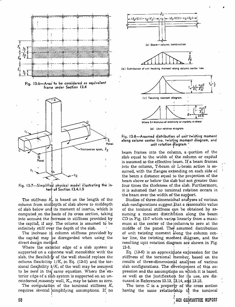
Fig. 13-6-Area- to be considerad as equivalenf frame under Section 13.4
Panel
.¡
C¡~
-<~ Fig. 13-7-SimplifJie: physical model illustrating thé in
ten of Section 13.4.1.5
The stiffness e is based on the length of the column from mid~epth of slab above to middepth of slab below antits moment of inertia, which is computed "on the asís of its cross section, taking into account the crease in stiffness provided by the capital, if an§. The column is assumed tó be infinitely stiff ov~ the depth of the slab. '
The increase i column stiffness providede by the capital may e disregarded when using the direct des~n met od. :
Where the ext rior edge of a slab system is supported·'on a c~crete wall monolithic with. the slab, the Hexibihtf of the wall should replace the column flexibility 1/Kc in Eq. (13-5) and the torsional flexjbility l:/K1 of the wall may be assumed to be zer6 in th~ same equation. Where the a exterior edge of a slf.b system is supported on an unreinforced masonliy wall, Kcc may be taken as zero.
The corhputatiÓn of the torsional stiffness Kt requires s'everal 1simplifying assumptions. If no
~ '
68
(o} Beom- column cambtnollan
(b} Dtslrtbultan af untt lwtslmc;¡ mamen! o long column center ltne
(e) Twtslmc;¡ mamen! dioc;¡rom
Where G= madulus al elosllctly ar rtgtdtly on sheor
(d} Uno! rotal tan dooc;¡rom
Fig. 13-8-Assumed distribution of unit-twisting momant along column center line, twisting moment diagram, and
unit rotation ~iagram ~
beam frames into the column, a rportion of the slab equal to the width of the column or capital is assumed as the effective beam. If a beam frames into the column, T-beam or L-beam action is assumed, with the flanges extending on each side oí the beam a distance equal to the projection of the beam above or below the sl~b but not greater than four times the thickness of ,the slab. Furthermorc, it is assumed that no torsional rotation occurs in the beam over the width of the support.
Studies of three-dimensiobal ana~yses of various slab configurations suggest lhat a r~asonable value of the torsional stiffness can be obtained by assuming a moment distriblition along the beam CD in Fig. 13-7 which varie¡s linearly from a maximum at the center of the ¡columne to zero at the middle of the panel. ThJl assum~d distribution of unit twisting moment 1long the column center line, the twisting morfient diágram, and the resulting upit rotation diagram are shown in Fig. 13-8. .
Eq. (13-6) is an approxirpate expression for the stiffness of the torsional member, based on the results of three-dimensionfil anal~ses oí various slab configurations. The development of this expression and the assumptiops on wbich it is based, as well as the justificatio~ for iÍs use, are discussed in References 13.13, ~3.14, a~ 13.15.
The term C is a proper1y of tne cross section having the same relatiorlship tá the torsional
• J j
~ ACI CO~MITTEE REPORT
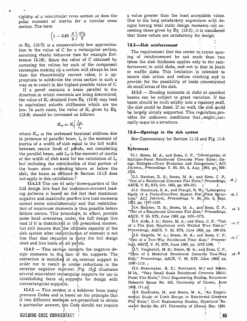
• rigidity of a noncircular cross section as does the polar moment of inertia for a circular cross section. The term
( 1 - 0.63 : ) x;y in Eq. (13-7) is a conservatively low approximation to the value of e for ·a rectangular section, assuming elastic behavior '(see for example Reference 13.16). Since the value of C obtained by summing the values for each of the component rectangles making up a section will always be less than the theoretically correct value, it i::. appropriate to subdivide the cross section in such a way as to result in tbe highest possible value of C.
If a panel contains a beam parallel to the direction in which moments are being determined, the value of K 1 obtained from Eq. (13-6) may lead to equivalent colurfm stiffnesses which are too low. In such cases, the value of Kt given by Eq. (13-6) should be increased as follows:
~ lsb Kta = Kt-1-" 8
where Kra 1s the mc'teased torsional stiffness due to presence of paralPel beam, I. is the moment of inertia of a width o~ slab equal to the full width between center lineS of pálnels, not considering the parallel beam, an'd Isb is lthe moment of inertia of the width of slab lhsed forl the calculation of I., but including the cohtribution of that portion o-f the beam stem exténding ~above or below the slab; the beam as d~fined fu Section 13.1.5 does not apply in this calctilation. ~
13.4.1.8 The use Of only: three-q uarters of the full design live load Jor makimum-moment loading patterns is basedl on th~ fact that maximum negative and maximu!m posd:ive live load moments cannot occur simultaneously and that redistribution of maximum mo!Jlents is thus possible before fail u re occurs. This procedtiJe, in effect, permi ts sorne local overstress under. the full design live load if it is distribut~d m th~ prescribed manner, but still insures that ;the ult~mate capacity of the slab system after red1stribut~on of moment is not lcss than that requir~d to G'arry the full design ciead and live loads o~ all pa~els.
t (' 13.4.2 - This sectiqn corr~cts the negatlve de-
sign moments to th~ face Qf the supports. The. correction is mod1fie1 at anp extenor support in arder not to result i;n und~e reductions in the exterior negative m~ment. :Fig. 13J illustrates severa! eqUJvalent rec~angula,r supports for use in cstablishing faces ofp suppotts for design with r.onrectangular suppoz:ts. ~
13.4.5 - This section is a holdover from many prevwus Codes and is, based pn the principie that if two different metheds are 1prescribed to obtain
~
a particular answer, tfle Cod~ should not require ; t - 1
BUILDING CODE COMMENTARY
a value greater than the least acceptable value. Due to the long satisfactory experience with designs having total static design monients not exceeding those given by Eq. (13-2), it is considered that these values are satisfactory for design:
1
13.5-Siab reinforcement
The requirement that the center to. center spacing of reinforcement be not more than. two t~mes the slab thickness applies only to the reinforcement in salid slabs, and not to that in joists ~r waffle slabs. This limitation is · intended to insure slab action and reduce crac}dng a:qd to provide for the possibility of loads concent,rated oh small 'areas of the slab.
13.5.2 - Bending moments in slabs at spandrel beams can be subject to great variation. If the bj:!am should be built solidly into a qasonry .wall, tl}e slab ~ould be fixed. If no wall, tqe slab qould b~ largel¡y simply supported. This regulation) provides for unknown conditions that ¡ might cnorIl'llally ocqur in a structure.
1 ¡3.6-0¡penings in the slab system
See Cop1mentary for Section 11.12 and Fig . .U-8. 1
Rflferences
'<L3.1. Sozen, M. A., and Siess, C. P., "Investigatipn of Multiple-Panel Reinforced Concrete Floor Slabs:~ Desi~n Meth~ds-Tl:eir Evolution and Comlj>arison,"1 ACI J<?URNAL, Proceedings V. 60, No. 8, Aug. t963, PP) 999-1028. :
:b.2. Hatcher, D. S.; Sozen, M. A.; and Siess, C. P., "Test of a -Reinforced Concrete Flat Plate,'l Proceedings, ASCE, V. !:H, ST5, Oct. 1965, pp. 205-231. f
l3.3. Guralnick, S. A., and Fraugh, R. W.\: "Labor~tory S~11dy of l\1 Forty-Five-Foot Square Flat !Piate Sjructuf'e," Aq JouRNAL, Proceedings V. 60, 1No. 9, fiept. 19p3, pp. 1107-1185. ] .
h4. Hatcher, D. S.; Sozen, M. A.; and J Siess, é. P., ll '
"Test of a :Remforced Concrete Flat Slab," Proceedings, ASCE, V. 95, ST6, June 1969, pp. 1051-1072.
b.5. Jida, J. 0.; Sozen, M. A.; and Siess, C. P., "Test of a Flat ;:¡Jab Re~nforced with Welded Yflre Fabnc," Proceedmgs, ASCE, V. 92, ST3, June 1966, pp. 199-224.
l ' p.6. Gatpble, W. L.; Sozen, M. A.; and Siess, C. P., "Test of a Two-Way Remforced Floor Slab," Proceed-
f ~ -ings, ASCEt V. 95, ST6, June 1969, pp. 10731·1096. <
•l ' "'\ ~3.7. Vanperbilt, M. D.; Sozen, M. A.; an~ Siess, C. P.,
"T~sts of a Modified Remforced Concrele Two-Way Sla!b," Proceedmgs, ASCE, V. 95, ST6, JJne 1969! pp. 10~-1116. t
1'3.8. Shewmaker, R. E.; Xanthakis, M.~ and Siizen, M. SA., "Véry Small Scale Reinforced Concrete MilltiPanel Flat Slabs," Civil Engmeering Studi~, Strucfa!ral Research Senes No. 265, University of Ilhnois, ~une 19tffi, 171 pp, f !
1a.9. Xanlhakis, M., and Sozen, M. A., ;~An Ex~erime~tal Stw;iy of Limit Design in Reinforc~d Coniete Flal Slabs,': Civil Engineering Studies, Structural Reseafch Seri~s No. 277, University of Illin01s, Dec. 1963.
t ; 1
~ 69
14 .¡
1~. 2.
,..,..r
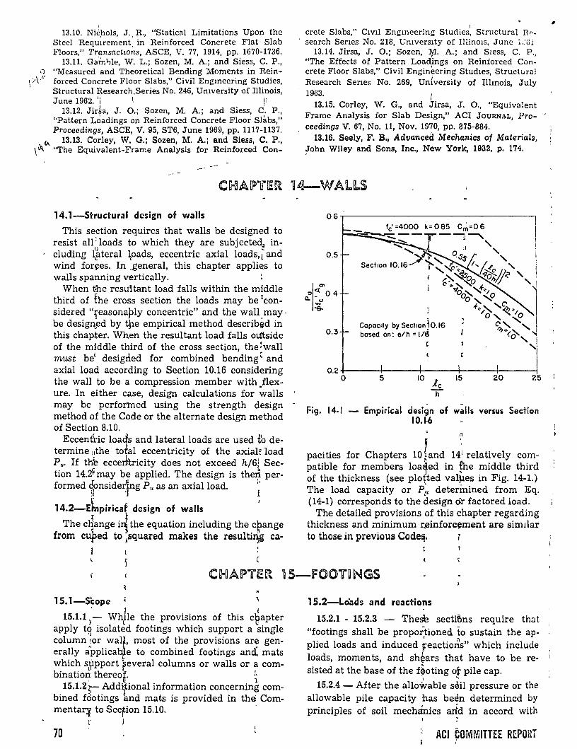
13.10. Nii:hols, J. R., "Statical Limitations Upon the Steel Requ~rement. in Reinforced Concrete Flat Slab Floors," Transactwns, ASCE, V. 77, 1914, pp. 1670-1736.
13.11. Ga'int¡le, W. L.; Sozen, M. A.; and Siess, C. P., 0 "Measured and Theoretical Bending Moments in Rein-
\v
\/ - forced Concrete Floor Slabs," Civil Engmeering Studies, Structural Research.Series No. 246, Umversity of Illinois, June 1962. 'i 1• (1
13.12. Jir~a, J. 0.; Sozen, M. A.; and Siess, e'. P., "Pattern L¿adings on Reinforced Concrete Floor Slabs," Proceedings, ASCE, V. 95, ST6, June 1969, pp. 1117-1137.
"' 13.13. Corley, W. G.; Sozen, M. A.; and Siess, C. P., \lA. "The Equivalent-Frame Analysis for Reinforced Con-
14.1-Structural design of walls
This section requires that walls be designed to resist all: loads to which they are subjecte~ including l~teral ~oads, eccentric axial loads,[ and wind for~es. In _general, this chapter appli~s to walls spanning vertically.
When fue resultant load falls within the middle third of the cross section the loads may be rconsidered "1easonaply concen trie" and the wall. m ay· be desigr:ted by ijle empirical method describ~d in this chapter. When the resultant load falls oUitside of the middle third of the cross section, the!wall must be" desigrled for combined bending' and axial load according to Section 10.16 considering the wall to be a compression member with .flexure. In either case, design calculations for walls may be perfortned using the strength design method of the Code or the alterna te design method of Section 8.10.
Eccent'ric loads and lateralloads are used t'o determine :1the total eccentricity of the axial~ load P •. If th~ eccerlrtricity do es not exceed h/6j Section 14.~ may be applied. The design is the~ per-formed éonsider~ng P" as an axial load. •'
~ 'l i
14.2-Ebpiricaf design of walls '
The c~ange i~ the equation including the crange from cuped to ,,squared makes the resulti~ ca·
1 crete Slabs," Civil Engmeering Studies, Structural Rr-search Senes No. 218, Umverslty of Il!inOJs, June 1.:G1
13.14. Jirsa, J. 0.; Sozen, M. A.; and Sress, C. P., "The Effects of Pattern Loadings on Reinforced Concrete Floor Slabs," Civil Engineering Stud1es, Structur<JJ Research Ser1es No. 269, University of Illmois, July 1963. 1
1
13.15. Corley, W. G., and Jirsa, J. 0., "Equivalent Frame Analysis for Slab Design," ACI JouRNAL, Pro- '" ceedings V. 67, No. 11, Nov. 1970, pp. 875-884.
13.16. Seely, F. B., Advanceél Mechanics of Materials, ~ohn Wiley and Sons, Inc., New York, 1932, p. 174,
06.----------------------------------,
0.5
"I<J.!;j> o 4 CL • u :e.
0.3
1
0.2 +-----+---+--~r-----1----1 o 5 10 i.c
h
15 20 25
Fig. 14-1 - Empirical design of walls versus Section 10.1-ó
n
pacities for Chapters 10 land 141 relatively com-patible for members loa<ied in ~he middle third
l ' of the thickness (see plo~ted val~es in Fig. 14-1.) The load capacity or P~, deterinined from Eq. (14-1) corresponds to the design ór factored load.
The detailed provisions of this chapter regarding thickness and minimum r,einforcement are sim1lar to those in previous Code~. 7
Cc-!JA~"'i~R 15-fOOTllNGS
15.1-Scope j (
15.1.1 >- Whtle the provisions of this c~apter apply t9 isolated footings which support a single column \Or wal~, most of the provisions are generally applicab[e to combined footings ancf, mats
1 ,,
which s¡rpport feveral columns or walls or a com-bination thereof. ~
' ~ 1 15.1.2 ;-- Addifional information concerning com-
bined fdotings and mats is provided in the Coromentar~ to Sec~ion 15.10.
r .l
70
15.2-Lo"ads and reactions
15.2.1 - 15.2.3 - The~ secti~ns require that "footings shall be propoitioned to sustain the ap- , plied loads and induced feactio~s" which include loads, moments, and sh~ars that have to be resisted at the base of the f~oting ot pile cap.
1 '
15.2.4 - After the allowable s~il pressure or the allowable pile capacity 'has been determincd by principies of soil mech<Ínics arfd in accord with
ACI COMMITTEE REPORT '
..
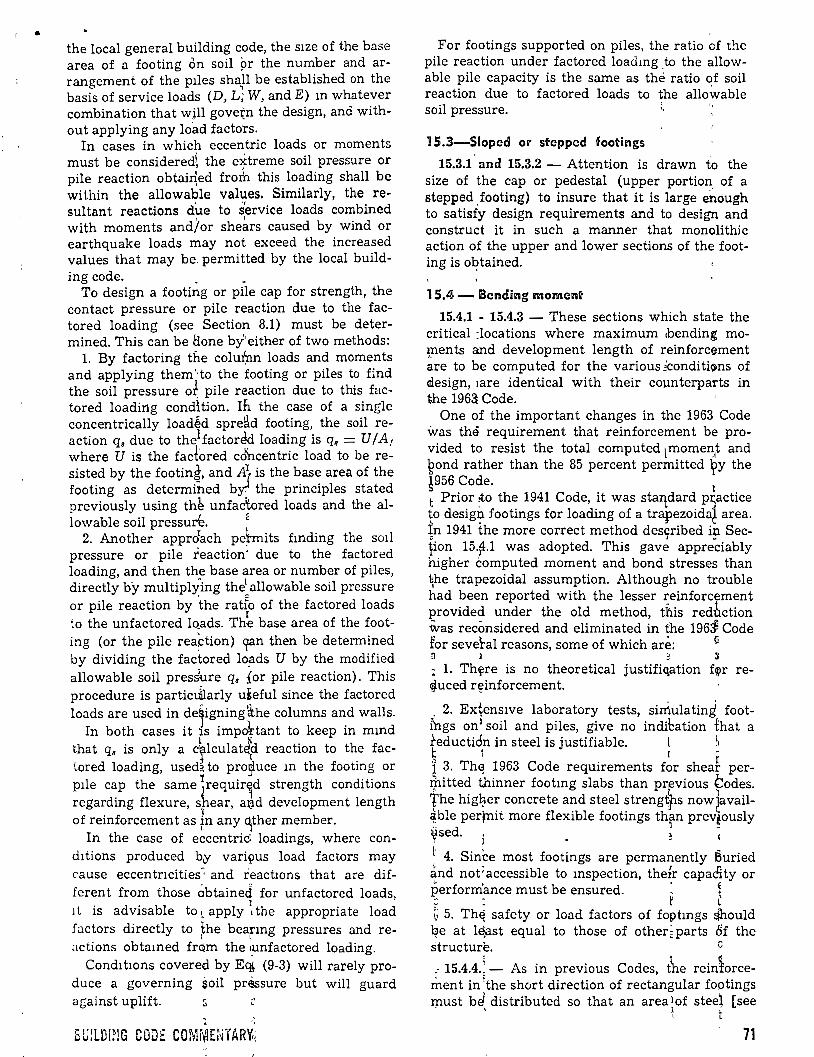
• the local general building code, the s1ze of the base area of a footing cm soil pr the number and arrangement of the plles shaJI be established on the basis of service loads (D, L; W, andE) m whatever combination that wjll govetn the design, and without applying any load factors.
In cases in which eccen'tric loads or moments must be consideredi, the extreme soil pressure or pile reaction obtai~ed frorh this loading shall be within the allowable values. Similarly, the re-
., 11 •
sultant reactions dile to service loads combmed ' l with moments and/or shears caused by wind or
earthquake loads may not exceed the increased values that may be. permitted by the local build-ing code. . _
To design a footing or pile cap for strength, the contact pressure or pile reaction due to the factored loading (see Section 8.1) must be determined. This can be á.one by'either of two methods:
l. By factoring the colufnn loads and moments and applying them'·to the footing or piles to find the soil pressure o~ pile reaction due to this factored loading condhion. In the case of a single concentrically loadéd spre~d footing, the soil reaction q. dueto the1factored loading is q. = U/A1
where U is the fac!ored cdincentric load to be resisted by the footing, and A~ is the base area of the footing as determiñed by:l the principies stated previously using th~ unfac~ored loads and the al-lowable soil pressur'e. ~
2. Another approrach pe~mits fmding the sml pressure or pile reaction' due to the factored loading, and then the base area or number of piles, directly by multiply-ing thel allowable soil pressure or pile reaction by .the ratfo of the factored loads
I to the unfactored lo_ads. The base area of the foot-ing (or the pile reaption) qan then be determined by dividing the factored l~ds U by the modified allowable soil pres~re q, {or pile reaction). This procedure is particJlarly uteful since the factored loads are used in de§igning'<the columns and walls.
In both cases it is impohant to keep in mmd that q. is only a crlculat~d reaction to the factored loading, used~ to pro~uce m the footing or plle cap the same ~requirÍd strength conditions regarding flexure, shear, aª'd development length ,, of reinforcement as fn any ~ther member.
In the case of eccentric: loadings, where cond!tions produced b¡y vari9us load factors may cause eccentncities~ and reactwns that are different from those Óbtained for unfactored loads, 1 l is advisable to ~ apply ~ the appropriate load factors directly to ~he bearmg pressures and re;¡ctions obtamed fr<)m the ~nfactored loading.
Conditwns coverecl by E<14 (9-3) will rarely produce a governing soil pressure but will guard against uplift. :; ::
For footings supported on piles, the ratio of t!1e pile reaction under factored loadmg ,to the allowable pile capacity is the same as the ratio of soil reaction due to factored loads to the allo~able soil pressure. :.
1 5.3-Sioped Oll' stepped foo"ings
15.3.1 and 15.3.2 - Attention is drawn to the size of the cap or pedestal (upper portian of a steppedfooting) to insure that it is large e~ough to satisfy design requirements and to design and construct it in such a manner that monolithic action of the upper and lower sections of the footing is o"~?tained.
15.4- Bending moment
15.4.1 - 15.4.3 - These sections which state the critical :locations where maximum ,bending mo~ents and development length of reinforcement are to be computed for the various iconditioms of alesign, 1are identical with their counterparts in the 1963 Code.
One of the important changes in the 1963 Code \vas the requirement that reinforcement be provided to resist the total computed lmome~1t and ~ond rather than the 85 percent permitted ~y the ~956 Code.
1 t Prior :to the 1941 Code, it was staqdard p~actice to desigJ?- footings for loading of a trapezoida~ area. ~n 1941 the more correct method des9ribed ip SecFon 15.fo.1 was adopted. This gave appreciably higher computed moment and bond stresses than ~he trapezoidal assumption. Although no trouble had been reported with the lesser reinforcement provided under the old method, tflis redbction tvas reconsidered and eliminated in the 19631 Code for seve~al reasons, sorne of which are: !l a l 2 ~
: l. Th~re is no theoretical justifiqation f~r re.¡Juced r~inforcement.
. 2. Extens1ve laboratory tests, sirrtulating footfugs onl soil and piles, give no inditation that a teductión in steel is justifiable. l ~~ ~ i r -1 3. Th~ 1963 Code requirements for sheaf per-I}litte~ thinner footmg slabs than prfvious ?odes. the h1g~er concrete and steel strengtps now~avail~ble per;nit more flexible footings th~n prevtously ~sed. i ' ~
l· 4. Since most footings are permanently 8uried ánd not; accessible to mspection, theÍr capadity or perform'ance must be ensured. : 1 ~ . ~ l G 5. Th~ safety or load factors of foptmgs $ould ~e at l$st equal to those of other~parts Of the structure. e
.- 15.4.4.;- As in previous Codes, the reiniorcement in 'the short direction of rectangular foptings must be! distributed so that an area lof steel [see . ' ~ t
71

Eq. (15-1)] is provided in a band width b, centered about,the column center line.
The remaining steel area required in the short direction is to be distributed equally over the two segments outside of band width b, one-half to ea'ch segment.
. To simplify placement of reinforcement, the intent of the requirement stated above may be satisfied by using an ~ncreased area of bars equal to
'A 2A,tf3 , sa= ,8+ 1
where A,, is the total area of steel in the short direction required by the Code, and by distributing the bars at equal spacings over the lengtl! of the footing.
15.5-Shear and development of reinforrcement
15.5.1 - The sh'ear capacity of footings must be determine'd for t~e more severe of the two conditions státed inl Section 11.10. The critica! ~ection is loca ted from the section specified in Sec-
" í ~ tion 15.5.1. However, a steel base plate can be so stiffened as to move the reference section to. the
1 E ¡ edge of the plate. t
The first condltion considers the footing essentially as ~ wide beam with a potential crack extending in a plane across the entire width. This case is analogous to a conventional beam, and the design proceeds accordingly.
L• The sec¡ond copdition assumes two-way ac;tion,
with pot¡ntial 1racking along the surface lof a truncateq cone or pyramid. The critica! section for this case is taken at a distance d/2 out from the perii?}'lery of the column, pier, pile or qther concentrated loap as compared with the distance d used px:~or to t~e 1963 Code. t
When j.he baslc strength design method o:f the Code is \lsed, ::¡hear design is accomplishe.il by using th~ soil b~aring pressure q. obtained f!rom the factored loatls and by using a shear capEacity reductio~ facto~ .p = 0.85 with the approgriate equationk of Chcwter 11. t Wher~ necesl\ary, perimeter shear aroun:ii in
dividual ~iles sHall be investigated in accord., with Section 11.10. if shear perimeters overla¡f, the
72
¡l
1 \ \ 1 ,,
l
/', --( Poló
..._¡~:~/~:_\-:_-=_-=_'~.,~·-=-=--.l....-Probobl~ cntlcol seCtiOO-
critica! perimeter b0 should be taken ~s that portian of the smallest envelope of individual shcar 'perimeters which will actually resist the critical shear for the group under copsidera~ion. One such situation is illustrated in Fig. 15-1.
When the alternate design method of Section ,8.10 is applied, the soil bearing pressures or pile reactions are those caused by the 1'service loads. Note that .p = 1.0 is used in the equations of Chapter 11 in this case. Note also 1that in)he 1971 Code, the limiting maximum stresses for 1shear must be
' '1 reduced to 50 percent of those computed in ac-cordance with Chapter 11, when fciotings are designed by Section 8.10. When lateral loads due to
. wind or earthquake are included in1the governing load combination for footings, advantage may be taken of a 25 percent reduction in required capacity, in accordance with Section 8.10.5.
When the intensity of thb bearmg pressures or pile reactions is not evenly distributed over the base area of the footing, the cross ~ection beyond
· which the soil pressures or reactidns are greatest should be used for proportioning the footing and selecting reinforcement.
15.5.4 - Development lengths are to be calculated according to Chapter 12, regardless of whether the design for strehgth is1made using the method of Chapter 10 or the alternate method of Section 18.10.
15.5.5 - This section iJ in priñciple the same as its counterpart in the 1963 Aer Code, except that the "6 in." dimension; previo'Osly used to determine whether or not a pile shall be considcred as contributing to shear,·· has b~en replaced by dp/2. Here, d11 is pile diaméter in fnches.
,, l ' '
15.6-Transfer of stress 1 at basé of column or pedestal Í [
15.6.1 - This section s~ates inf~general that all forces applied at the column basr must be tronsmitted to the footing. Alf tensil~. forces, whether created by uplift, moment, or other reason, must be resisted entirely by rei~forcerrfent.
Past Codes required tl'¡e stres~ in longitudmal bars to be transferred b~ steel. For compression, this Code is more liberal .~ince st.eel must be pro-
t I u
Fig. 15-1-Modified -critica! section¡for perimeter shear with overlapping critica! ~erimeters
l ACI FOMMITTEE HEPO~i
i r 1
1 j
•

vided only for the excess force which cannot be taken in bearing.
15.6.2- 15.6.3- Compressive stresses may, within the permissible limits,' be transmitted to the footing by bearing. For s~rength design, permissible bearing stresses on the actual loaded area will be equal to 0.85q,fo' (where ,,, = 0.7), when the loaded area is eau.:d to 1.he ~~ wvtich it is supported. Ther~fore, t.Yla perUI!55tbfe bearing stresses will be approximately v.J; c. of the weaker concrete on the common1loaded area.
In tne common case of a column bearing on a footing larger than the column, bearing stress must be checked on the · bottom of the column and the top of the. footing:. The permissible bearing stress on the column will normally be 0.6fo' of the column concrete. Strength in the lower part of the column must be checked since the column steel cannot be considered effective at the joint beca use the stress in it is ·not developed for sorne distance above the joint \mless dowels are provided or the steel is extended into the footing. The permissible béaring siress on the footing may be increased in accordance with Section 10.14.2 and will usually be twd times b.85ct>fc' or approximately 1.2fc' of the foohng concrete. The compressive force which exceetls that developed by the permissible concrete rbearing stress on the bottom of the column or on the tdp of the footing must be carried by dowels Ór extended reinforcement.
Similar procedures apply where a column rests on a pedestal and where a pedestal rests on a
' footing. · ' For the alternaté desigrt method of Section 8.10,
permissible bearing stressés are 50 percent of those for the strength design rri~thod.
15.6.5 - The Code does 'not require that all bars in a column be extended tj.uough and be anchored into the footing. Howevet, steel at least equal to 0.005A 11 or an equal arfa of properly spliced dowels must exteiid into ·the footing with proper anchorage, where~ A 11 is ¡ the supported column cross section. At feast fobr bars or dowels must be used, and thet diameter of the dowels shall not exceed that of the column bars by more than O 1- . t j . ::>m. . r 15.6.7 - The shear-fr'iction method given in
Chapter 11 may b1e used 1 to check for transfer of transverse forces from tlie base of a column to a footing. Shear kJys or ;other devices must be used where additional ;capacity for transverse force is needed. ~ ~
15.6.8- Lap splices of ';#:14 or #18 column bars to dowels from tpe foottng are specifically per-
mitted by this section. The dowel bars must be smaller in size than the #14 or #18 bars. The development length for the dowel into the column must correspond to that required for the #14 or ·#18 bar.
This provision is an exception to Chapter 7 of the 1971 Code, which prohibits lap splicing of ·these large bar sizes. This exception results from many years of successful experience with the lap splicing of #14 and #18 column bars with footing dowels and recognition of the practica! advantages of this construction method.
15.7-l?edestals and ~ootings o~ unrein~orc:ed c:onc:rete
15.7.3-The crack-free entity of a pile cap transmitting concentrated loads of large magnitude is extremely important, because stress redistribu~ion due to the loss of effectiveness of a pile f,an be 'critica!. For this reason, use of unreinforced con'crete for pile caps has been proriibited f>y the 11971 CÓde. l 1
[
15.1 0-l-Combir.ed footings and mats 1 ' i 1 15.10,1 - Any reasonable assumption w~th re-1spect to the distribution of soil pr~ssure 9r pile .reactions can be used as long as it is consistent :with the type of structure and th~ prope;1ties of ,the soi~, and conforms with estabhshed principies of soil mechanics (see Section 15.1). Similarly, as ·prescri,bed in Section 15.2.4 for iso}ated footings, 1the ba¡;e area or pile arrangement of combined footing_s and mats must be determj.ned using the
1unfactored forces and/or moments transmi~ted by
1the foqting to the soil, considering,.allowaQle soil 1 pressures and allowable pile reactiops. ~:
Design methods using factored loads an¡;l capa-• t '
· city r~duction factors can be applied t~ com-l bined Jfootings or mats, regardless of the soil . pressure distribu tion.
A r~port of ACI Committee 436, "Suggested 1 Desigri Procedures for Combined' Footings and tMats,"1 was published in the ACií JouRNÁL ProJ ceedin~s V. 63, No. 10, Oct. 1966, pf>. 1041 ~o 1056; ! also ACI Manual of Concrete Practibe. That report 1 shoul~ be used for guidance where áppropr~ate.
Referenc:es ,1 • 1
~ 15.1. ¡;Kramrisch, Fritz, and Rogers, :faul, "Sijnplified Design ;. of Combined Footings," Proce1_dings, J1SCE, V. 87, No. _SM5, Oct. 1961, p. 19. -
15.2. "Teng, Wayne C., Foundation Design, ~rentice' Hall P.ublishing Co., Englewood Cliffs, N. ~., 1962, 1 466 pp.¡
73
General
Precast concrete is simply remforcéd concrete cast in units which are assembled and fastened together on the job. The regular provisions for reinforced concrete thus apply except for a few specific variations.
The practice related to design and construction of precast concrete structural elements differs in sorne respects from .that for cast-in-place concrete structural members.' Where provisions for cast-inplace concrete apply equally to precast concrete, they have not been repeated in this chapter. Similarly, items · related to prestressed concrete in Chapter 18 and composite concrete construction in Chapter 17 that apply for precast concrete (or overrule similar sections given elsewhere in Úfe Code) are not stated in this chapter.
More detailed recommendations concerning precast concrete have been provided in the following ACI standards and reports by ACI committees: 1
l. "Recommended Practlce for Manufacturéd Reinforced Concrete Floor and Roof Units (ACI 512-67)" ~
2. "Suggested Design of Joints and Connections in Precast StructUtal Concrete," by ACI Corn-mittee 512, Aug. 196'1 I
3. "Mininrilm Re1quirements for Thin-Sectidn Precast Conhete Cq_nstructwn (ACI 525-63)" ~
In contra~t to t~ 1963 Code, items related 1o precast concrete cdncerning aggregates, concrele cover for reinforce~ent and splicing of reinforcl:::ment are now conkolidated in other sections Úf the Code. L'arger ~ize aggregate for precast cohcrete is nd longéT speciflcally permitted btit waivers of size lÚrÜts are allowed under Section 3.3.2. e E
There is ho longer a minimum size stated for columns as 1in prev~ous versions of the ACI Code. However, w,hile fir~ ratings do not fall within t~e purview ot the Ab Code, the designer is ca.Utioned that. the general buildmg code must
1
be consulted i~ this re~pect. The actual fire rating i~ a function of both the cover over the reinfortement and the relatlonship between the volume 'of
1 . ,, :i a member and lts ·exposed surface area. In using very small ~columr?s, therefore, due consideratÍon
4 -~ •
must be g~en to~ fire ratings. Similarly, wh,l:m chemical ar¡.d corrbsive considerations are nec~s-sary, the d s1gner ¡;must use judgment tempered ~
1 '1
by availabl ,' test d~;-a. ~ \ 16.1-Scop~
~ . '
The term "und~r plant controlled conditio~s" does not Spfcifical~y imply that precast memb~rs
74
must be manufactured in a plant. Structural elements precast at the job site will also qualify under this section if the control of form dimensions, placing of reinforcement, quality control oí concrete, and curing procedute are equal to that normally expected in a plant ..
The tolerances required by Section 7.3 are considered as a minimum acceptable standard for precast concrete.
16.2-Design
While the design for precast elements is developed as for cast-in-place elements (except as provided in Chapters 17 and 18), special considerat¡ons are necessary for precast members. The loads imposed on precast elements during the period from casting to placement may be greater than the actual service loads. Handling procedures roay often cause permanent deformations. Hence, special care must be givent to the:l methods of transporting and erecting of precast members.
., It is also vitally important tb consider the effects Oí connections and interconnected elements with respect to precast members. The structural behavior of precast elements lmay differ substantially from that of similar members that are castin-place and are monolithic. Design of joints to transmit iorces due to shrinkage, creep, temperature, e las tic deforma tion, wipd forc~s, and earth-5luake forces require partictllar care in precast ~lements. The details of sucl~ joints ~re extremely ~m portan t. 1 Cracking of concrete must'be controlled so that 'the load carrying capacity will not be reduced. : 1 l : Precast members may b~ desigqed using the ~eneral strength design provJsions qf. the Code or ¡the al terna te design method~ provid~d for in , Sec·,tion 8.10. l • l• : 16.3-Bearing and nonbeari.ng wai\~ panels
t Bearing and nonbearing walls that are precast 1must be designed accordingEto Chapters 10 or 14. iThe alternate design method of Section 8.10 may ialso be used. 1 ~ 1
)1 6.4-Details
~ The safety factor of 4.0 prÓvides a~ least. 100 per-1cent impact possibilities duÍ'ing erection. The in\ent of this factor is to avold a brÍttle failure of \he insert. It is not intende~ that ~ny additional -el> factor or load factor be u!>ed. ~ ' . '
?,
ACI COi'M1HHEE REPORT
..
Reinforcement should be provided adjacent to lifting devices to withstand, all temporary forces.
~1 The Code requires adequate performance at ser-
vice loads and adequate st'rength under factored loads. However, handling loáds should not produce permanent stresses, strains,' cracking, nor deflections inconsistent with the provisions of the Code.
17.1-Scope
17.1.1 - The scope of this chapter is intended to include all types of composite concrete flexura! members including composite single-T or double-T members, box sections, foHied plates, lift slabs, and other structural elements, all of which should conform to the provisions o~ this chapter. In sorne cases with fully cast~in-plade concrete, it may be necessary to design 5the in~rface of consecutive placements of concrete as r~quired for composite members: Composit,e str~tural steel-concrete members are not covered in this chapter, since such sections are covered in the "Specification for the Design, Fabrication and Erection of Structural Steel for Buildings," published by the American Institute of Steel Construction (AISC).
17.1.2- The Code in its entirety applies to composite concrete flexura! members except as specifically modified in Chapter 17. For instance, deep composite secti~ms sh¿ll be designed in accord with Section 1d:7 and h.9. When composite concrete flexura! me~bers ~re subjected to axial
. loads, Section 10.8 abd 10.9~ and 10.10 (or 10.11) apply. The alternat~ design method of Section 8.10 may also be U5ed: '
17 .2-Ceneral consideration~ : ~
17.2.1 - This sect)on pe¡¡fnits the designer to use any or all of th~ variou¡~ components in supporting the load in th!i! most expeditious manner.
17.2.3 - Tests to Cdestrudtion indicate no dlfference in strength of shored and unshored mem-bers. l¡
17.2,.5....:.. The extenf of cradking permitted is dependent on such factob as environment, aesthetics, and occupancy. In addition, cfpmposite action must not be impaired. ( ~
1 17.2.6 - The premature loading of precast ele-
mcnts can cause exckssive deflections as the re-r
sul t of creep and shr;inkage.t This is especially so at early ages when the moisture content is high and the strength low. ·.
The transfer of shear by fiirect bond is essen-J •
t1al 1f excess1ve deflection ftom slippage is to be l:
BUILDING CODE COMME~J'fARY E
The foregoing remarks apply also to prestresscd a'nd composite construction.
1 ,. . 16.6-Transportation, storage, and erection ~
. '· , It is important that all temporary erection' con-n~ctions,, bracing, and shoring be shown o~ the shop drawings.
prevente~. A shear key is an added mechanical factor of safety but it cannot operate until slippage occurs.
17 .3-Shoring 1The próvisions of Sections 9.5.5.1 and 9.5.5.2 must
be considered with regard to deflections of shored artd unshbred members. Before shorin~ is removed it should be ascertained that the strength and sarviceability characteristics of the structure¡_ will not be impaired.
17.5-Horizontal shear
"17.5.1 +- The full transfer of horizontal shear • ¡
between segments must be ensured by contact stresses or properly anchored ties, or both.
17.5.2 - Tests17·1 indicate that horizontal shear d0es not 'present a problem in T-beams wherl the pertion b'elow the flange is designed to resist the vertical shear, the interfaces of the components are rough and mínimum ties are provided acccirding to Section 17.6.1. The ties must be extended aoross the joint and fully anch<pred on 1both si~es of :the joint in accord with S~ction ~2.13. Tl)ese coQ.siderations may be used witp other11 seg-mental sqapes. 3
l17 .5.3 -;- The calcula ted horizontal ~¡Shear ~tress represen~s the force per unit area of intE>rface. When the design is developed using the alternate m,thod qf Section 8.10, V .. is the shear due to dead and live load calculated using unity load and cf> .·factors~ Also, when this method is'used ahd a coEmbination of gravity loads and wind and e1rth-qdake lodds govern, Section 8.10.5 appl~es. .
17.5.4-;r'he permissible horizontal slíear stresses, vh; apply; when the design is based ~m the ,load fa~tors an'd cf> factors of Chapter 9. When the <:!ltern~te desifn method of Section 8.10 is used; the value of vh should be reduced iJ~ a.cco~dance with h1 L h ' . l " lO, 3 t e provis10ns for s ear stress-es 'l'l-t:lectton IJ. • •
'In reviéwing composite cor¡..erete fL¿,:ural n;1embeh for :serviceability at service lo~ds anct for harndling ;and construction loads, V u fina y b~ repl~ced bi the service load shear or hahdling Joad sh~ar in ~q. (17-1). The resulting ser~ice loa.~ or
¡ 11 ....
. -1 75
handlmg load horizontal shear stress should be compared {vith th~ allowable stresses (0.55 vh) to insure tliat an a~equate factor of safety results.
17.5.5. -·· Prope~ anchorage of bars extending across joints is required to insure that contact of the interfaces is m~intained.
1
~ i
17.6-Ties·. for ho;~izontal shear
The mínimum afeas and maximum spacings are based on test data~ given in Reference 17.1. ' . -
': 17.7-Measure of:, roughness 1¡
This section coftforms with the provisions- of Chapter 11, and is based on tests discussed in Reference 17.1.
References
17.1. Saemann, J. C., and Washa, George W., "Horizontal Shear Connections Between Prec'ast Beams and Cast-in-Place Slabs," ACI JouRNAL, Proceedings V. 61 No. 11, Nov. 1964, pp. 1383-1409. '• ;: '
17.2. Hanson, N. W., "Precast-Prestiessed Concrete Bridges: (2), Honzontal Shear ConneCtions," Jou:rn<J.t PCA Research and Development Laboratories, V. 2 No. 2, May 1960, pp. 38-58. Also, Devel~ent Depart~ ment Bulletm D35, Portland Cement As~pciation. ' 17.3. Mattock, A. H., and Kaar, P. H., "Precast-Pre:·stressed Concrete Bridges: (4), Shear Tests of Continuous Girders," JournaL, PCA, Research and Development Laboratories, V. 3, No. 1, Jan. '1961, pp. 47-56. Also, Development Department Bulletin D45, Portland Cement Association.
- 17.4. Grossfield, B., and Brinstiel, C., "Tests of TBeams with Precast Webs and Cast-in-Place Flanges," ACI JouRNAL, Proceedings V. 59, No. 6, June, 1962, pp. 843-851.
1
CHA~üiE!R 18 - !?RESVRIESSr!lD> CONCIR.!Eü~-
18.1-Sco~e 18.1.1-The provisions in this chapter were de
veloped primarily for structural members such as slabs, beams, a~d columns which are commohly used in blilildings~· However, many of the provisions may be apP,lied to other types of construction such
1:as pre~sure vessels, pavements, pipes,
and crossties. Th~ application of the provisions is left to thJ j udgmten t of the engineer in cases-not specifically cited iÍn the Code.
18.1.2 ankl18.1.3_:_The entire Code applies to prestressed c¡oncrete¡ except where excluded 01¡ in direct conpict with Chapter 18. Sorne sectio~s of the Code are exc1uded from use in the desigv. of prestressed conc~ete for specific reasons. "The following discussion provides explanations 1 for such exclusions: l
Sectionj 8.6-Section 8.6 of the code is excluded smce moltlent redistribution for prestressed concrete is covered i~ Section 18.12.
Sections 8.7.2/ 8.7.3, and 8.7.4-The empihcal provisionJ of Sec?tions 8.7.2, 8.7.3, and 8.7.4 fJr Tbeams \~re deyeloped for conventional feinforced concrete and if applied to prestressed rconcrete wo~ld exdude many standard prestrJssed products _?n sati#actory use today. Hence, ~roof by exper~ence pefmits variations.
By exc~uding ~ections 8.7.2, 8.7.3, and 8.7.4, no special r~quirem-ents for prestressed concretfe Tbeams appear in ;~he Code. Instead, the determination o_f az: effec~fve width of flange 1s left td the expenenée and j'udgment of the engineer. ~here possible, 'the flange widths in Sections 8.7.2, 8.7.3, and 8.7.4 shoulq be used unless experience has proven that variations are safe and satisfac_tory.
""" JO
,
It is not necessarily conser~ative il~ elastic analysis and design considerationj) to us~ the maximum flange width as permitted iro Sectioll 8.7.2.
Sections 8.7.1 and 8.7.5 prt>Vide general requirements for T-beams that are¡ also applicable to prestressed concrete units. Tljle spaqng limitations for slab reinforcement are based on flange thickness, which for tapered flanges can be taken as
· the average thickness. ~ Section 8.8-The empirical limils for concrete
joist floors are justified for conventional 'reinforced concrete but not for prestresséd concrete. ' Hence, they are excluded in prestressed concrete. Experience and judgment must be used.
Sections 10.3.2, 10.3.3, Hf-3.6, 10.5, and 10.9.1 -For prestressed concrete, the lim~ations on rein-
1
forcement given in Sectiops 10.3~, 10.3.3, 10.3.6, 10.5, and 10.9.1 are replaced by tbose in Sections 18.8, 18.9, and 18.14.
Chapter 13-The design bf preshessed concrete slabs requires recognition °of secohdary moments
¡¡ 1 induced by the undulating proflle of the pre-stressing steel. Also volmpe cha~ges due to the prestressing force can cre~te ad~tional loads on the struct¡¡re that are not; adequªtely covered in Chapter 13. Because of these unique properties associated with prestressiflg, marly of the design procedures of Chapter 13 !are not' appropriate for prestressed concrete structures ánd are replaced by the provisions of Section 18.13. r
e t Chapter 14-The requirements.c stated for wall
ciesign in Chapter 14 ar~ largeli empirical, utilizing considerations not; in tended to apply to prestressed concrete.
-'
ACI CGMMITTEE REPORT
...

... 18.2-Ceneral con~idera2"idns
18.2.1-As has been past practice in the design of prestressed conhete, tlle design investigation should include all load stages that may be significant. The three ·majar '1tages are: (1) initial stage, or prestress ~transfer stage-when the tensile force in the p~estressed steel is transferred to the concrete and~stress levels may be high relative to concrete cylinder,; strength, (2) service load stage-after ldng-timé volume changes have occurred, and (3) ~the de'sign load stage-when the capacity of th~ member is checked. There may be other load stages that require investigation. For exampl~, if th~, cracking load is significant, this load stage may require study, or the handling and transporting-· stage may be critica!.
From the stand¡:>.oint of; satisfactory behavior, the two stages of ipost irtwortance are those for serviCe load and design load.
Service load stage refers; to the loads defined in the general buildutg code[ such as live load and dead load, while the design load stage refers to factored loads. When calculating the behavior at the service load stage, tPi.e cp factors given m Chapter 9 should nbt be itlcluded. It is necessary to investigate service load ~nd design load stages to insure member performance in regard to both serviceability and capacity.~
For example, a beam s could be prestressed along Its longitudinal axis \n such a manner that It will support the ~pecifietl loads without objectionable deflection lbut the, strength 'could be below adequate safety requ1rements. Sirnilarly, a des1gn based on st~ngth ¡1lone may provide unsatisfactory behavibr at service loads, e.g., excessive camber or d~flection.
This means that:. the actual design should be performed for stre'hgth, ~sing load factors and understrength factors. Then, an investigation a t service load leJels is ~ecessary to determine the approximate stresses ~at service loads. For beams without axi~l loads; the classical straightline theory is satisf~ctory. for sections with axial load, a general anhlys1s considering the stressstrain diagram for ~concre~ is desirable. In this respect, a bilinear approx~mation of the stressstrain diagram for l?restrespmg steel IS advisable. Section 18.3.2 provi?es ass~mptwns that may be used for mvest1gatfn at ~ervice loads and after transfer of the prestressing .force. ·
18.2.4-This refer~ to thJ type of post-tensioning where the tenaon mákes contact with the prestressed concretJ memH.E~r mtermittently. Precautions should be ~taken to prevent buckling of such members. In o particúlar, if thin webs or flanges are under ~gh pr4compression, bucklmg IS poss1ble between ~supports of slender members.
If the tendon is ~n complete contact with the member being prest~essed, br is an unbonded ten-
~ ,•
BUILDING CODE COM~ENTARY
don in a duct not excessively larger :than th~ tendon, it is not possible to buckle the· member under the prestressing force being intro~uced.
18.3-Basic assump11'ioli"ils
The provisions which referred tci modulus of elasticity of steel and concrete in the 1963' Code have be'en removed from this chapter. For values of E,, Section 8.3.2 requires that tests •be performed or that data be obtained from the manufacturer. for concrete, Ec may be taken as Ec:= wl.533Y fe' '(see Section 8.3.1).
18.3.2-Assumptions are provided for use in service load investigation and for review of sections at 'transfer of prestress forces. Note thát this section does not apply to the design of compressien members in general, but only to members that arelprestressed. 1
e 18.i2 (e) In cons1dering the are~ of the- open ducts, fue critica! areas should ihclude those fhich ~ave coupler sheaths which may be of a larger size than the duct containing the tendon. Also in :sorne instan ces the trumpetJ or tradsition piece .frl:>m the conduit to the anchdrage may be l>f such a size asto crea te a critica! area. e ~ 8.4-Permissible stresses in concl'ete-Fiexural c¡¡ember:;
1 Permissible stresses in concrete are given to control serviceability. They do not ¡mtomatically guarant~e adequate structural caRacity, ¡which Jtnay be ·checked in conformance wit:h other3 Code ~eq uirerpen ts.
s 18.4.1-4--These stresses are applicable immedi!tely after transfer of the prestressing force but prior to~ the occurrence of time-dep~nden t flosses ~eh as ~reep and shrinkage. The cor{crete stresses ~t this ~tage should not exceed the recomm~nded ~alues <faused by the force in the ste,:el at tr!-nsfer J!educed: by the losses due to elastic :Shortenjng of ~he concrrete, sorne relaxation of the] steel, ~lip at ªnchorage, plus the stresses due to ¡he weight of the member. Generally, shrinkage IS not included élt this stage. These stresses apply tOl both pfetensxioned ~nd post-tensioned concrete with proper rpodific~tions of the losses at transf~r that ~pply.
18.4~1(b) The stress limit 3V f' c1 ~efers t<) loca~ons of \tensile stress in a member, pther t];1an in tpe precompressed tension zone, such as ~t the ~nds of ¡a simply supported beam :rtear th~ top. \Vhere ~he tensile stresses exceed \he allorvable ~alue the total force in the tensil~ stres5:: zone spould ~e calculated and reinforci.J¡g steel pro~ortionep on the bas1s of this force ~t a str.fsS of Q..6f11, bU¡t not more than 30,000 psi. rit sho'!ld be 1~oted that the effects of creep alJ.d shnnkage 15egin to" reduce the tensile stress ah:host imh1edi-. .
•' .~
77
ately. Sorne tension remams in these areas after a11owance is made for all prestress losses.
18.4.2.2 'Í1he precompressed tension zone is that portian df the rriember cross section in which flexura! tensi,bn occ&s under dead and live loads.
di 11
Prestressed concretej is usually designed so that the prestress] force Jintroduces compression into the zone, thus effec~vely reducing the magnitude of the tensile
1stress. :;
'l'hlil pcl."missibllil hmsillil stress 6'{'!7 is compatible with ,the cor+crete covers required by Section 7.14.1.3. For c'onditions of corrosive atmosphere, whiCh is defined as an atmosphere in wh1ch chemical attack such as seawater, corrosive industrial atmDsphere, sewer gas, or othe:.r highly corrosive atmospheres are encountered, greater cover than that required by Section 7.14.1.3 shol);ld be used, in accordance with Section 7.14.3, and tension stresses reduced to eliminate possibl¿ crackihg at service loads.
The engi&eer m!ust use judgment to dete}mine the aroount of increased cover and whether reduced ted'ion is r~quired. :.
., '
The allow;able concrete tensile stresses depe~d on whether :or not ~nough bonded reinforceme(lt is provided to control cracking. Such bonded steel may ~pnsist ~f bonded prestressed or no?prestressed .. tendor¡.,s or of bonded reinforc~g bars. It should be IfOted that the control of crasking depends,not on};;r on the quantity of reinforqement proviried but. also on its distribution ov:er j ,, ) the tension ¡;one. ~ · .
Because ;9f the .1bonded steel requirements ;,f Section 18.~, lt is qpnsidered that the behavior 1of segmenta! IJlemberp will be generally compara~le to that of ~imilar\y constructed monolithic cqncrete mem~ers. Tlferefore, the permissible tensile stress limi* of Se~tions 18.4.2.2 and 18.4.2.3 ap~ly to both s~menta~ and monolithic members.d If deflections\·are imnortant, the built-in cracks: of , ''t"" ' segmenta! members should be considered in the computatiahs.
1 l
18.4.2.3: The <\1lowable tenslle stress 12W represents ¡1 an incre.as~ over the va~ue listed1 in ACI 318-63 · to pertmt 1mproved serv1ce load P,erform~nce, ... especiaf.ly when live loads are o~ a trans1ent nature. [To take advantage of the .,increased allowable~stress, the engineer is requi~ed to increasJ the concrete protection on the r~inforcement,; as stip'ulated in Section 7.14.2, anci to investigat~ the '\kflection characteristics of ~the member p~rticulaflY at the load where the mCijmber changT.s from~ uncracked behavior to cracfed behavior. .
The loa~-deG.:c.Lion curves of prestressed ~oncre.te merrifers mry be 1dealized mto an assUI;ped b1lmear c~rve. T~e first portian of the curve :1s a straight li~e front; initial load up to the load ~hat
78
causes cracking of a magnitude suffici~nt to sigmficantly reduce the member's¡ stiffne~s. The second portlon of the curve proce,eds from this poin t
• 1 1
of crackmg at a flatter slope as load is increased. The change in slope is a function of the reduction m moment of inertia at cracking. For; most usual conditions the change is negligible. In sorne cases the change is so gradual that ~he assJmption of a bilinear curve is not necessar'y. Hov/ever, where the reduction in moment of ipertia ~an be large a t etuc:king, tho loss of stiffncsl'J, or ín~rosBé in do· flection is large. For this reason, whEm the higher allowable stress is used, the engmeer is directed to compute the deflection, using the cracked cross section and the transformed areas o·f bonded steel to compute thé moment of iriertia.
18.4.3-Prestressed concrete, is largely a plan twoduced manufactured prqduct 'rith rapidly c;hanging technology. This · section_ provides a r):lechanism whereby develoP,ment <{f new prodl,lCts, materials, and techniqúes need not be inhibited by arbitrary limits cin stres~ which rep-J L -resented the most advanced requirements at the ~ime the Code provisions :were ~dopted. Apl?rovals for the design shou~d be i11 accordance with Section 1.4 of the Code. . L
18.5-Permissible stresses i~ steel r.
The Code no longer distinguishes between temporary and effective steel stresse~ as did the J.963 Code. The reasoning is {hat the, tendon stress ¡mmediately a'fter transfer Cil.n preV.ail for a con"siderable time, even after the struc·ture has been pu t in to service. This stress,. therefo¡:e, must ha ve .an adequate safety factor pnder ~ervice condi. tions and cannot be considered as· a temporary :stress. Any subsequent str!fss dro§ in the steel due to losses can only imérove cpnditions and, hence, no allowable limit oq stress ~rop has been provided in the Code. ' '
18.6-Loss of prestress " . 1
. 18.6.1-The causes for lpss of, prestress are hsted. For an explanation of 'how to,compute these losses, see the reports of ÁCI-ASf:E Committee
· 423* and ACI Co~mittee ~435.t T~e lump sum
1 losses of 35,?00. ps1 for prE1tensiox:tng and 25,000 for post-tenswmng that apP¡_eared in the report of
. Committee Á23 generally g~ve sati#actory results : for many applications. -
Actual losses, greater or ;:,1.1~•~ •<-'1' •ll1an lhe lump sum values, have little fHect ~n the design strength of the m'-'r,<ber, biut affect service load
' •ACI-ASCE CommJttcc 423, "Tc;tatlve R.l.commendations for
Prestrcssed Concrete," ACI J'Ot1RN.U. ProcceHmgs V 54 No 7 Jan. 1958, pp. 545-578. 1 ' • • • •
tACI Comm1ttee 435, "Deflections of Ptcstressed Concrete Mcmbers," ACI JouRNAL, Procecd11lgs V 60. No 12 Dec 1963 pp. 1697-1728. . . . • . '
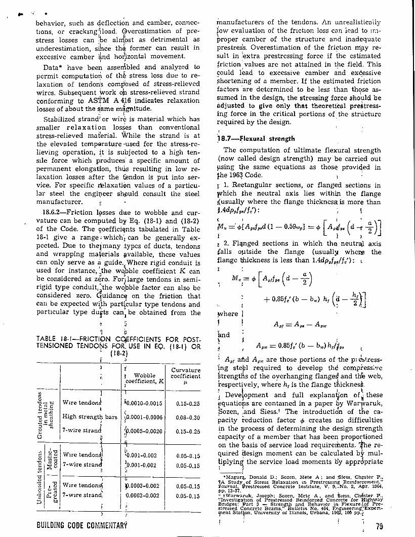
behavior, such as deflection and camber, connectwns, or crackmg ~load. G>verestimation of prestress losses can :be alrrfbst as detrimental as underestimation, sfuce th~ former can result in excessive camber ánd hofizontal movement.
1 ,
Data* have been assen\bled and analyzed to permit computation of th~ stress loss due to relaxation of tendoris com~osed of stress-relieved wires. Subsequent Work o~ stress-relieved strand conforming to ASi'M A 4).6 indica tes relaxation losses of about the s'ame m~gnitude. , r
Stabilized strand) or wire is material which has smaller re laxa tion loss1es than conventional stress-relieved matérial. While the strand is at the elevated temp&~rature -used for the stress-relieving operation, ~t is subjected to a high tensile force which produces· a specific amount of permanent elongation, thus resulting in low reIaxation losses after the t:endon is put into service. For specific r~laxation values of a particular steel the engi~eer sh:!)uld consult the steel manufacturer.
18.6.2-Friction l~sses dlie to wobble and curvature can be computed by Eq. (18-1) and (18-2) of the Code. The ~oeffici~nts tabulated in Table 18-1 give a range ~ which! can be generally expected. Due to the]many .types of ducts, tendons and wrapping ma~erials ¡¡wailable, these values can only serve as a guide. Where rigid conduit is used for instance, ~the w~ble coefficient K can b_e _considered as. z~ro. For) large tendons in semingid. type condult~t~e wopble factor can also be cons1dered zero. ~Uldanc~ on the friction that can be expected with particular type tendons and
1, ' particular type dufts can
1 be obtained from the
·¡ o TABLE 18-1-FRICTICN CqEFFICIENTS FOR POSTTENSIONED TENDONS FOR. USE IN EQ. {1 8-1) OR
~ ( 1 8-2)
1 W1re tendonJ
l
High strengt(l bars J ,
7-wire strand 1 ~
1 6-o 1
;!; - c:J W1re tendon~l o ........ J -e:: "'ca ~ 8 7-wire stran
§ ~ ü-~ J "'C 1 i :: 1 1 ~ W1re tendom;~ o 1 c:J ~ ' ~ 1 ¿; C:J 7-wire strand-- ... ' :::;¡ ~ -
~
t J Wobble coefficient, K r
;0.0010-0.00151
\ ~0.000 1-0.0006
l ,p.ooo5-o.oo2o -" .1 ll •0.001-0.002 1
1 ~0.001-0.002
11T
~.0003-0.002
ú.0003-0.002
BUILDING CODE COMiviENTARV
Curvature coefficient
IL
0.15-0.25
0.08-0.30
0.15-0.25
0.05-0.15
0.05-0.15
0.05-0.15
0.05-0.15
manufacturers of the tendons. An unrealistica!ly iow evaluation of the fnctwn loss can lead to 1r.1-~
proper camber of the structure and inadequatc prestres's. Overestimation of the frictwn rriay result in !extra prestressing force if the esti~ated friction' values are not attained in the field. This ~ould l~ad to excessive camber a-nd exc_essive ~hortening of a member. If the estimated friction factors ·are determined to be less than those assumed in the design, the stressing force sho~ld be adjusted to give only that theoretical prestressing force in the critica! portions of the structure required by the design. '
) 8.7-~lexural strength
The computation of ultimate flexura! strength (now called design strength) may be carried out llsing t(le same equations as thos~ proviqed in t;he 196~ Code. ! l. Rectangular sections, or flanged sections in lVhich the neutral axis lies within the flange iusually where the flange thicknesst is more than j_.4dppfps/fc'): ( 1 1 ' -
!1111 =' </>[Apsfpsd (1 - 0.59wp] = </> [ ApJp• ( d -r ~ )J j l ); ~ 2. Flqnged sections in which th~ neutr<\1 axis talls outside the flange (usuall)f whe~ the flange thickness is less than 1.4dpPfP,,/fc'): L 1
M<= <1> [ Aptfp• ( d- ~ )
~here
1 knd ~
+ 0.85J/ (b- b1c) h¡ (~- ~)]
' Apoc = 0.85jc' (b - b,.) h¡/fp•
(
Ap1 al'ld Apoc are those portions of the p1 Eh.t.ressing ste~l required to develop the compress~ve ~trengt¡l¡s of the overhanging flange~ and th'e web, ~espectively, whe~e h1 is the flange tllicknes~. ~ 1 1 \ J Deve~opment and full explanat¡on of~ these fquatiops are contamed in a paper by War¡varuk, pozen, :and Siess.t The introductiÓn of the capacity reduction factor <1> creates no difficulties ~n the ¡¡>rocess of determining the design strength capacity of a member that has been proportioned on the basis of service load requirements. 1he required tlesign moment can be calculated by mul~iplyin~ the service load moments oy apprÓpriate
•Magur::~. Donald D.; Sozen, Mete A ; and ~less, Ch~ster P., 'lA Study.., of Stress Ra!axat10n m Prestressmg Remforcement." lTournal, .trrestressed Concrete Instltute, V. 9, "No. 2, At>r. 1964, pp. 13-57. ' '1 tWarwaruk, Joseph; Sozen, Mete A, and S1ess. Chéster P .. '!Investlgatlon of Prestressed Remforced Concrete for Hlghway Br1dges: Part 3 - Strength and Behav10r in• Flexure l.of Prestressed Concrete Beams," Bulletm No. 464, Engrneermg:'ExpenljOCnt Stat¡on, Umvers1ty of Ilhnols, Urbana, 19112, 105 pp.[
! 1 79
load factors and then dividing by the 4> factor. Member capacity is then determined by the above formulas without the 4> factor.
18.7.1-Eq. (18-3) is a shortcut approximation to the more accurate calculation which involves a trial method based on reaching compatability between stresses and strains. The approximate formula may u'nderesúmate the capacity of beams with high percentage~ of steel and, for more accurate evaluations of their capncity, tho strossstrain compatability rnethod should be used.
Eq. (18-4) for unb~nded members is up-dated on the basis of more ~ecent test data. A recent report* recommended toe equation
1
. 1.4fc' fps = fsc + 10,000 + 100 PP
ACI-ASCE Committee 423, Prestressed Concrete, felt tq~t the ~ slightl~ more conser~at~ve values resultipg fron:¿. droppmg the 1.4 mult1pher for fe' would be preferable.
J j
The equation provides a conservative value representing- the lower envelope of data on the increase of ,tendonl stress as various members were test-loaded to¡ failure. It should be recognized that v~ry sti!f members, such as a posttensioned de.ep beam, may not deflect enough to develop the t increaS¡e in stress reflected by this formula.
:e e Frequentl:(, in Jtractice, prestressed concrete
members ar~ propoEtioned on the basis of stresses at service load and the strength checked for adequate safetyl using 1these equations to determine steel stress at design loads (factored loads).
1 8.8-Steelt' perceniage
18.8.1-T~e limit~tions on the reinforcing steel index of 0.3, wasi originally set by ACI-ASCE Committee ~ 423, Prestressed Concrete, as fue dividing line betw~en under-reinforced and ov~r-reinforced membets. ."
~ . ;· When t~e rein~rcing index exceeds 0.3, ~he
·strength ~s prec;icted by standard equatiQns (without the .p) d.oes not correlate well with \est results. l ~
18.8.2-Tpe equ~tions to be used for compu\ing the flexur~l strenpth of over-reinforced memqers can be th~ same as those in the 1963 Code. The f?llowing rquatiofs satisfy the intent of this ~ec-han: t 1
For rectangula!1 sections, or flanged sections in which the;neutra\axis lies within the flange: ~
j M";u = tP (0.25f/bd2) ~
For flartged seetions in which the neutral :axis falls o u tside the qange: f M.,= <j>[0.25f/b,~d2+0.85f/(b-b,c) ht (d-0.5~/)]
80
.. 18.8.3-This prov1s1on is a precaution against
abrupt flexura! failure resulting from fUpture of the prestressing steel when failure occurs iinmedia tely after cracking. The usual ~ember requi~es considerable additional load bey:ond cracking to reach design capacity. Thus, cdnsiderable deflection warns that the design capacity is being approached. However, if d,rsign c~pacity occurs shortly after cracking the warning deflection may not occur.
18.9-Minimum bonded reinforcement require~ ments
The possibility of the formation of excessive cracks in flexura! members with unbonded tendons must be taken into consideration. The increase in allowable tensile stress permitted in the C<bde requires mínimum bonded relinforcement far both beams and slabs.
The amount of steel used ls propbrtioned accórding to Eq. (18-5), based on the amount of tension N e in the concrete computed on Cthe basis of an uncracked homogeneous eohcrete section, or
. Eq. (18-6). These provisions ~ and ofuers en unbonded prestressing have béen adaipted from a r'eport of ACI-ASCE Committ~e 423.t i 1 Unbonded reinforcement in accordance with
Sections 18.9.1, 18.9.2, and 18.9.3 provides adcquate crack control when the allowable tensile stresses of Sections 18.4.2.2 and 18.4.2.3 are used. · For two-way slabs the min~mum ~mount is in~ended in each direction. However,~ for two-way ~labs, Section 18.9.3 perffi:its th~ amount of ponded steel required, to .. be deqreased when the tension in the precompx¡essed t~nsile zone at s~rvice load does not exceed ,zero. Tl¡l.is is in agree-. ' ment with the 1963 Code o~ which~current satis-l-1ctory design practice has ~een b~ed. The word
1 "uecreased" is used in plac~ of "eliminated" be.c<~use, although satisfactory;behavi,pr is achieved 1
w: thout bonded flexural steel, cli;rrent practice
1 calls for a nominal amoun~ of bo!'fed reinforce
, ment at joints between slctbs and¡ at supporting columns to insure flexural continuity and/or
1 l.
1 1, s~1car resistance.
, 'j 8.1 0-Repetitive loads
The effects of repetitive ioads cause difficulties r ,·i.marily in fatigue of th~ anchotage or tendon 1 ¡,aterial and in loss of bortd strerlgth of the concrete. The latter aspect is of importance where
\
--~kl. Jun; Kattula, Bas11 ~.; and I\~ttock, Alan H , "A Compar1son of the Behavior of P~-Tensio ed Prestressed Ccn· e:-ete Beams Wlth and Wlthout Bo d," Repo SM69·3, Un1vers1tY vf Washington, College of Enginee g, Stru tures and Me<:hanJcs. Dcc 1969. ,
tACI-ASCE Committee 423, "T~ntative áeconunendaUons for Concrete Members Prestressed 'tfth Unbo)'.lded Tendons," AC! JounNAL, Proceedtngs V. 66, No. 2! Feb. l!lt!9, pp. 81-26. ·
~ ACI CQIVlMITTEE REPORI' _,_
.../

.. • the ava!lable transfer length of pretensioned tendons is short, such as inl railroad crossties.
The warnmg acramst diagonal tension cracking b' 1
at 1·epetitive loads lower ,in magnitude than the static loads used for des1gn indicates that It would be prudent to use at least.,the mínimum shear reinforcement expressed by: Eq. (11-1) or (11-2), even though tests or calculations based on static loads show that shear r~lnforcement is not required.
18.11-End regions
Because the actual stresses are quite complicated around post-tensioning anchorages, the only rutional approach _ is to .apply strength design methods.
A refined strength analysis should be used whenever possible,1with q,~being taken as 0.9.
The 1963 Code formula L
l 3--f cp = 0.6f' e~: ...Y Ad A1
but not greater tl'lan f'c, lmay still be used as a guide for determifüng permissible bearing stress when experimental data ór more refined analyses are not available. This fo:Pmula is used without a q, factor. l ·,
In the equation for fcp
A1 = bearmg a~ea of anchor plate of post-tensioning st~el
A~ maximurh· area rof the portien of the anchorage surface that is geometncally similar to, and concentric with, the area of the anc!lor plate of the post-tensioning steel
fcp permissible concrete bearing stress under the anchor platel of post-tensioning steel with the énd anchorage region adequately reinforcecl
1 a.l2-Continuity1
As member ca~acity js approached, melastJc behavior at sorne· sections can result m a redistnbution of moments in prestressed concrete beams. Recognition of thi's actual behavior can be advantageous in ~design Ll under certam circumstances. A ngoro\ls design method for moment redistributwn lS quite complex. However, recognitlOn of moment redist'ribution can be accomphshed with the simple ::method of permitting a reasonable adJustment olf the elastically calcuiated design load moments. The amount of adJustment must be¡kept wühin predetermined safe lim1ts. ~
The amo un t of! redistrlbu tion allowed depends on the ability of the critica! sections to deform inelastically by a sufficient amount. Serviceability
BUILDING CODE CO~MENTA~V
under service Joads is taken ca!:"c of hy the limiting stresses of Sectwn 18.4. The cholCL oÍ 0.20 as the largest tension reinforcement mciex, wp, (o,+ "'P ~ w') 1 Or (ww + Wpw- Ww
1) f0r Which rediStflbU
tiOn of moments is allowed, is in agreemen~ with the requirements for conventionally reinforced concrete of 0.5pb stated in Section 8.6.
! The secondary bending moments 'produced by the prestress force m a nonconcordant tendon disappears at the capacity at which, due to plastic hinge formation, thc structurc becomes stutically determínate. Therefore, the design load moments at the critical sections of a continuous prestressed beam are only those due to dead and live loads.
With unbonded tendons, sufflcient bonded steel must also be provided to assure the rotational ~capacity required at the sections where plastic
1hinges : develop. The bonded steel, requin~d by !¡Sectio11¡ 18.9 may not be sufficient fo~ this purpose.
t18.13-1 Slab systems t : This : section does not provide d.etailed Code provisi?ns for design which will account fo¡: such taspects. of behavior which are u~ique tp pre-<stresse~ concrete. >
' t In a~dition to the more accurate theories for ianalysis, the classical elastlc slab theory or finite ¡elementts or finite difference methods are often ¡used for analysis. The frame meth-od also1 is apJplicable to square or rectangular panels when colurnns are relatively stiff and rigidly connected
' -1 to the ¡slab. Where columns are qqite fle'9ble or ,are not ngidly connected to the s\ab, th€¡ frame
1 metho~ is sometimes simplified ,into 3;1 beam .;metho~ in which the slab is analyzrd as b«jams in each of the two directions. Simplified methods
- ) ' , using average coefficients do not apply fnr pre-• 1 1 L ~ stressetl concrete. ¡
~ Con~erning the strength of prestressed slabs, tests i:pdicate that strength is controlled primari-
' \ l ly by the total amount of tendon ~apacitY:I rather , than by tendon distribution. Sorne ~endon~ should : be pa~sed through the columns Of aroun
1d their
i edges. }t is suggested that the maximum sptlcing of ; tendoqs in the column strips sho1¡1ld not~exceed
1 four ti¡nes the slab thickness and
1that thr maxi
i mum ~_pacing in the middle strips should ,not ex-ceed six times the slab thickness.
\ ¡ 1 L '
1 For ¡prestressed flat slabs contirtuous oyer two , or more spans in each direction, ~t is s~gested that tlie span-thickness ratio should gener~lly not
: excee~ 42 for floors and 48 for ¡roofs aFd that these Jimits may be increased to l48 and1 52, respectively, 1f calculations verify tla.at botln shortand lang-term deflection, camber, and vibration frequ~cy and amplitude are no~ objecífonable.
81
Short- and long-term deflection and camber should be computed and checked for the requirements· of serviceability of the particular usage of the structure.
The maximum length of a slab between construction joints is generally limited to 100 to 150 ft to minimize the effect of slab shortening, and to avoid excessive loss of prestress due to frktion.
18.14-tompresolon mamboro-Comblnod axial load and bending
18.14.1-For compression members having less than 225 psi prestress, the mínimum vertical reinforcement required in Section 10.9.1 for columns or in Section 10.16 for walls must be provided.
18.14.2-Prestressed concrete compression members will, in most cases, be precast and pretensioned. The high quality control associated with this type of construction may result in smaller column dimensions than those required by the 1963 Code. Since the effects of accidental loads, local buckling, long-column action, shrinkage, creep, and nonuniform temperature distribution must be considered in the design, mínimum column dimensions are not required in the Code for either reinforced or prestressed concrete. For somewhat similar reasons, the mínimum amounts of reinforcement, specified in Section 10.16 for walls, need not apply to prestressed concrete walls, provided the average prestress is over 225 psi and a complete structural analysis is made to show adequate strength and stability with lower {1tnotmt.q of reinforccment in kecping with productlon pructlee. Wnll.'l wlth nn tWCl'II!.:Q pt'e:ltt·c:m less than 225 psi can be treated as reinforced concrete walls and the provisions of Chapter 14 or Section 10.16 used.
18.1 S-Corros ion protection for unbonded tendons
Suitable material for corrosion protection of unbonded tendons should have the following properties:
l. Remain free from cracks and not become brittle or fluid over the entire anticipated range of temperatures. In the absence of specific requirements, this is usually taken as Oto 160 F
2. Chemically stable for the life of the s~~ucture
3. Nonreactive with the surrounding materials such as concrete, tendons, wrapping, or ducts
4. Noncorrosive or corrosion inhibiting:
5. Impervious to moisture 1
18.17 --Crout for bonded tendons
Grout is the means by which bond is provided between the post-tensioni~g tendons ,and the
82
concrete and/or by which corrosion protection • of the tendons is assured. Proper grout and grouting procedures, therefore, play an important ,part in post-tensioned construction. There are various recommended practices for grout materials a'nd gro u ting procedures, such as those in "Recommended Practice for Grouting Post-Tensioning Tendons," July 1967, Tentative, prepared jointly by the Prestressed Concrete Manufacturers Association of California, Inc., and Western Concrete Rlilinf()rcin~ Stool Institu.te.
18.17.1-The limitations on water, Section 3.4.1, and on admixtures, Section 3.6.1, are intended to apply to grout. Aluminum powder or other expansive admixtures, when approved, should produce an unconfined expansion not greater than 10 percent.
18.17.5-Quick-set grouts, when approved, may be shown by tests to require shorter periods of protection and the recommendations of the suppliers should be followed.
18.19-Application and measurement of prestressing force
18.19.1-This section contains requirements to insure that the amount of tension assumed for the steel in design is actually placed in the steel. A similar provision appeared in the report of ACI-ASCE Committee 423 arid in the 1963 Code.
18.20-Post-tensioning anchorages and couplers
lR.:!O,l-Jn p,ivinP, the capacity of anchorages ancl cou plers it ls in tcnclecl thu t thcy ucvelop the specified strength of the tendon steel with a mínimum amount of permanent deformation and successive set, recognizing that sorne deformation and set will occur in testing to failure. Bonded tendon anchorages that develop less than 100 percent of the mínimum specified strength of the tendon steel should be used only where the bond transfer length equals or exceeds that required to develop the tendon capacity. This bond length, as determined by test, should be provided between the anchorage and the zone where the full prestressing force will be required under service loads and design loads.
18.20.3-For eletailed recommendations on tests for static and cyclic loading conditions for tendons and anchorage fittings of unbonded tendons, see Section 4.2.3 of "Tentative Recommendations for Concrete Members Prestressed with Unbonded Tendons" ACI JOURNAL, Feb. 1969.
It is suggested that the elongation requirements for tendon assemblies in Section 4.2.3.2 of this report be reduced from 21/2 to 2 percent -ro conform to more recent recommendations.
ACI COMMITTEE REPORT
19.1-Scopc and deí-initiol'ls
Thin shells (except for domes) and fold¿d plates are usually classified ·as short, intermedia te,
' 1• and long span, depending on'.the ratio of transverse span to longitudinal span, ori the ratio of the radius
11 ,, of curvature in the. transv:.erse d1rection to the
' ~.
longitudinal span. ~ d Far sl1ort span be;'rrel sh~lls, the load is trans
ferred to the end ar,bhes aria to edge beams in a complex manner. Arch action is predominate over membrane action. Oii. the other hand, in very long span barrel shells, tl).e shell· .acts very much as a beam10 1 having a curved Or folded CrOSS section. The ratios of width or radius of curvature to length for which arcp actior_t, true shell action, or beam action occur will differ with the shape of the structure.1D :2 ~
Since this chapter. applies to thin shells of all shapes, extensive dis~ussion related thereto is not possible in this Com:rhentary. The reader is therefore referred to the references for further information.
Elastic analysis wilth resp'ect to shells refers to any method of struetural inalysis involving assumptions which provide suitable approximations to three-dimensional·,1.elastlcrbehavior. Such solutions range from sirhply saltisfying three-dJmensional statics10 1 to ~ soluti'on involvmg eighthorder partial differehtial e4uations.10·3
Elastic analysis rtveals the concentration of forces in certain locations. For example, in a short barrel shell, the tenslion is cfoncentrated near the lower edges. In an ell}ptical ~arabol01d the tension builds up to a peak hear thé corners. In a dome, high tension forces generally occur near the boundaries. If a designer w~re to design a barrel shell by the ordinary beam OJ arch theory and not recognize its limitatiq_bs he c'ould erroneously predict the required amount and. distribution of reinforcement. The elasti;c analy:sis permits a reasonably realistic evaluation oY deflection. This important consideratfun is ffequently overlooked by sorne designers. ' ~
l -The degree of accuracy re~uired in the analys1s
of a thin shell structre wip depend on certam critica! factors. The incltt~e: the s1ze of the structure, the geomet: and ~gree of curva ture of the surface, the typet:of bou1dary conditwns, and the nature of the load. g.
Modern techniquesJ· sed 13~ electronic computer solutions include proc dures · uch as the finite element method whic resul in rigorous solutions10 4 •10 40 predictmg prirlcipal stresses and their directions at várious riodes as well as the maximum · shear stre~ses and their directions at various nodes.
BUILDING CODE COMMENTAHY ;.
Such techniques provide solutions· whicll' are usually superior to conventional solutions ~inasmuch as .the reinforcement may be plp.ced as, theoretically required to resist principal tensile
- ll' 1"
stresses and maximum shear stresses. ExteJ;J.sive discussion concerning the directions of such stresses is provided in Reference 19.5 ¡iwith re'gard tt) domes, eylindrical shells, and shdrt and Jong
' t " barrel shells. ~
Reference 19.6 provides theoretical concepts related to thin shells and References l9.7 through 19.11 provide theoretir.al as well as practical design concepts related to thin concrete shells. Finite element methods for shells are thoroughly; dis-cussed in References 19.12 and 19.13. ~ ·
lrhe rémaining references provide excellent gUidance concerning analysis, design, and constDlction "of shells of various types. Iu particular,
~ ' 1 l
Rrferenc~ 19.15, the report of ACI Colljlmittee¡334, P)Ovides an excellent reference for th~ design engipeer, tl¡.e constructor, and the fiel~ inspe,ftor. T~e ACI {v'Ianual of Concrete Practice'EPart 2,
1also
p~~>Vides ~ood guidance with regard ~ shells.!
1 ~.2-Ayumptions fl'he designer may assume that concrete 1s
ideally el~stic, homogeneous, and isotropic, ha.ving idtentical stress-strain properties in al~ directions. F~rther, Poisson's ratio may be assurr¡ed equ~l to zero in the partial differential equations related to the partiqular type of shell being designed. The W(j)rd "may" in this section allows the use of sitnplifica;tions that do not provide errors of large
• t r m§lgnitude under usual conditions. H~wever,, the k11ow ledgeable analyst-designer m ay y tilize If!Ore acfurate ~ssumptions.
~ ~
1 ~.3-Ce~eral considerations 1 1 -. 19.3.1 -r- Equilibrium investigatio~ are- re-~ e ,_ 1
qqi.red to jnsure that statics wlll be sat~fied. .1
~9.3.2 --;- Solutions which do not satisfy s~ress anb strail}. compatibihty may be used., only when ex,_tensive1experience has proved that safe designs ha~e res4lted from their use. Such rpethods! inclltfde beam type analysis for barrel~ shells ~and fo!,ded pl~tes having large rabos of spp.n to w~dth or:Jradius pf curvature, simple membr~ne ana~ysis for~ domes¡ and shells of revolution, an¡d others in wqich the, partial differential equatwns relate4 to sta:t1cs ar~ satisfied while the strain com~ati-bi~ty equ~tions are not precisely satisffd. , ~oweve.r, in complex structures of l~rge ra~ius
a 2pore a'furate analysis should be usfd. Greater accuracy pf analysis is also warrant~d in l~rge strl.rctureslin areas of high wind intensity and in
1, ,. .. ..
critical earthqunke zones. Finite element methods can be used to satisfy statics and strain compatJbility as well as ~o satisfy the boundary condi~ tions. Sine e numerous simultaneous differen tial equatwns result fro~ such an analysis, electronic computers provide tp.e only feasible method of obtainmg a solution. ~
19.3.3 - Model :analysis may include straip. mcasurements or pllotoelastic studies of portions
• 11 of the shell bemg an~üyzed. :i
Wind tunnel tests:'of a scaled-down model do not neccssarily provide. usable results. Many factors enter into model tests besides shape and direct scale. 1!l 30 Tnus, the. Building Official should accept results of model tests in lieu of mathematic.fil analysis only when the model tests have been performed under the direction of a proven expert in this area of. structyral engineering, including e:?'pertJse in the theo~y of models and si mili tu de pf model and wototyne.
19.3.4 - The sh.ell elements must be proportwned to S<!tisfy tlp.e strength prov1s1ons requir~d. by the Code, while the analysis must be m~de using elastif! analysis theory, the elastic theory of models or 1 combi:pation thereof. ~he shell thi9knes:,, how1ver, isr not always d1ctated by the strength requirem~nts determined from such an analysis b~t ofteri' by deformation of edge m~.m-
' ll ' .... bers, structural stability, and required cover orer the reinforfement.E e
The necfssary .strength must be provi~ed e ~y usmg either of t.pe two methods prescnbed; m Section 8.1: The permiss1ble maximum steel ra~ios,
\ '
p, may not be ex~eeded. i
If the shell is~ pres~ressed, then i ts . ul tinp ~e capacity must be ~vestlgated, as well as lts ela:>tlc capaclty ~nder sfrvice load~, the cracking .l~ad, and the loads indl,_fced at the tlme of prestressu~.
If comppsite astion is involved, the provisj~ns of Chaptei 17 murt be satisfied. Chapter 16 ap:p,hes íf element¡; are pr<ecast.
19.3.5 _; Supwrting frames and edge be:ams must be 4es¡gne1 in accord with the general!proviswns of this ~ode, using either of the two methods prescibed in Section 8.1. Portions of the shell may be u~ilized as flanges for trans~erse
.. l arch-frarrfes or longitudinal frames. Such fl~ges m ay be c~rved of sloping. Can tilever action of the flangcs must beJ investigated in determining remforcem~nt in !he flange perpendicular tq' the longitudinal ax1s of the supporting membér, as
' J 1 requircd ;by Ch~pter 8. In all cases, temper,fture remforce
1ment ~ust be used. 1,
19.:~.6 ~ The ~esigner is directed to considar the poss1ble reducti9n in the buckling capacity ~ue to creep and othe~ factors. Reference 19.17 projvides theoretJC_al and !practica! guidance for the effects
1 t ·' of creep.,
·' 84
19.5-Reinforcemen~ requiremeilt'S '
19.5.4 - The option of increasing the deviation from ihe line of the prmcipal stress may be apphed when excess steel is used, but the total steel atea per foot may not exceed 3.6fc' lfv nor 14,-,. 500hffv when the deviation exceeds 10 deg.
. · Only the membrane stresses need be considered in determining the maximum Cieviatioh allowed. . Development of reinforc~ment must satisfy €hapter 12 and splices must satisfy Chapter 7.
1
19.5.6 - Typical locations ;¡..rhera it may be dc-sJrable to concentrate tensile reinforcement rather than distribute it over a zorie of varying tensile stress are near the edges of long barrel shells and near the ring beams in domes. Where this is done, mínimum distributed reinforcement in the amount of 0.35 percent is specified to control tracking throughout the tensne zone.
19.5.7 - The effects of moments at boundaries and other locations where rrlembrane action must Jbe considered, require that sufficient strength be 1provided to resist the resul t:ing principal stress es land shear stresses. Axial loads must be included when they are sufficientíy 9-arge to cause an in-
Jcrease in the reinforcementc requirements. If factored axial loads exceed 0.1fc'bh in any section,
: cf>=0.7 must be used, even ¡though~there may be only one line of reinforce¡¡nent i~ the direction
: being considered. For lessej axial: loads a linear . increase in cf> is used fro:tp 0.7 é\t Pu/fc'bh=0.1 . to cf> = 0.9 at P,. =O, in ac;cord with Chapter 9. :Principal stresses are converted to,forces per foot ; and then the strength prqvisions :4 are used. The . design stress is then 0.85cpf e' over the en tire cross ; section of concrete in coxppressi?n and cpf 11 for
steel in tension, except as modified under Section ) ' 19.5. L
In shells where complex stres~ patterns may exista comprehensive matfiematic~l analysis must be utilized. It is dangerou~ to use simplifications m such cases. 6 S
S ) The foregoing discussi?n reg<Vding principal
stress lines and deviations of r~nforcement direction therefrom refers to gravity load analysis, that is, dead load, vertickl live 'load, and snow load. The effects of wind toad mu\t be considered as well as the effects of ~arthquake forces when appropriate. Additional re~nforce~ent in different directions · (than those required for gravity loads) may be required for sucli lateral' loads. Due consideration must be given t~ suctior effects.
When shell or folded Plfte ele~ents are precas:. and connected by cast-in-place s~gments, composite action must be considered. Tlie dead load forces will cause stresses a~d defl~ctions due to ar, entirely different type o~ behav~r than live anci wind load, after the se~ents afe connected and respond to loads by shell <action. s
l
ACI COMMITTEE REPORT
• -e;

1
1!>.5.8 and 19.5.9 - The ~esigner must considcr thc possibility or probabilirly of the reinforcemcnt bcing placed out of line dn doubly curved surfaces thus resulting in inshfficient splice lcngth ¡f precut reinforcement is u~ed. The designer must provide sufficient reinforcement length to maint~ün the minimum splice ~ lengths required by Chapter 7. ·¡
19.6.-....Prestressing ,
Axial forces due to draped prestressed tendons may not lie in one ~~lane, and due consideration must be g1ven to the resulting force components. The provisions of Chapter 18 apply in segments or sectrons where prestressing-is used. The effects of post-tensioning of supporting members on the shell must be taken into account.
J 19.7-Construction <
When early remmlal of forros is necessary, buckhncr and deflection fuust bei investigated to estab-o 1
Iish the modulus- óf elasticity required befare rcmoval of forros. '!'he modulus of elasticity of thc concrete must be measured using a stressstrain curve for the field cured specimens. It is not sufficient to determine the modulus from the
cquation Ec = 33wl.5Y fe' with f! determined for the fJeld-cured spedmen.
References
19.1. Chinn, James, ?'Cylindrlcal Shell Analysis Simplif¡ed by Beam Method," ACI ,JOURNAL, Proceedings V. 55, No. 11, May 1959, pp. 1183-1192. Also, Discussion by M. S. Ketchum, A. L. Parmt< and H. W. Conner, A. S1ev, Anton Tedesko, _Alfred tweig, and Autho!, ACI JouR;<;AL, Proccedings V. 55, Dec. 1959, Part 2, p. 1:>83.
19.2. Salvadori, Man'o G., "Shell Versus Arch Action m Barrel Shells," Proceeding.t, ASCE, V. 81, No. 653, July 1956. ~ .1
19.3. "Design of Cy~indncal~ Concrete Shell Roofs," Manual of Engineerin Pract1~e No. 31, Amencan Soc¡ety of C!VJI Engineer , New York, 1952, 177 pp, (Prepared oy Alfred Parrrle undet: the direction of ASCE Struclural Division Cqmmitte~ on Masonry and Rein-forcecl Concrete.) E
19.4. Scordelis, A. C.; Ram1rez, H. D.; and Ngo, D., "!I'Iembrane Stresses 1'n Hypefbolic Paraboloid Shells Having a Parallelogram S ha pe" m Plan," ACI JouR:-lAL, Proceedmgs V. 66, No. 12, Dec. l:969, pp. 994-1000.
19.5. Molke, Ene C., tJnd Kal\nka, J. E., "Principies of Concrete Shell Dome pesign,"1ACI JOURNAL, Proceedmgs V. 34, No 5, May-'June 19~8. pp. 649-707 (with ex:. tens1ve 3Ibliography). ¡
19.6. T1moshenko, Sí, and ~Voinowsky-Kneger, S., Theory of Plates and. Shells, <McGraw-H!ll Book Co, New York, 1959, 580 pp. ;¡
19.7. Pfluger, Alf, E(.emcnta71Y Statics of Shells, Second Ed1tion, McGraw-.H!ll Bodk Co., New York, 1961, 122 pp. (Translated from Gerl!lan by Ervm Galantay.)
19 8. B1llwgton, Dav¡d P., Tl\tn Shell Concrete StructHrcs, i\ícGrnw-H1ll Bopk Co., New York, 1965, 332 pp.
19.9. Haas, A. M., ~estgn ó1 Thin Concrete Shells, J ,hn W!ley and Sons, Ipc., ~e\'4York, 1962, 128 pp.
j
BUILDING CODE COMMENThRY e:
19 10. Gibson, J. E., Lmear E~asttc Theory of Thm Shells, Pergamon Press, New York, 1965, 182 pp.
19.11. Salvadori, Mario, and Levy, Matthys, StmcturnL D1esign in Archttecture, Prentice-Hall, In.c., Englewood Cliffs, N.J., 1967, 457 pp. (Example problems and solutibns by John J. Farrell.)
19.12. Soare, M1rcea, Application of Fmite Differencc Equations to SheH Analysis, Pergamon Press, New York, 1967.
19.13. Zienkiewicz, O. C., and Cheung, Y. K., The Finite Element in Structural and Continuum Mechanics, McGraw-Hill :Eléok Go., New York, 1967, 274 pp.
ill.l4. Mast, Flaul EL, 11Ileslgn and Construotlon ot Northlight Barrel Shells," ACI JouRNAL, Proceedings, V. 59, No. 4, Apr. 1962, pp. 481-526. (wlth extensive Bibliography).
19.15. ACI Committee 334, "Concrete Shell Structures - Practice and Commentary," ACI JOURNAL, Proceedings V. 61, No. 9, Sept. 1964, pp. 1091-1108. (Corrections and Discuss1ons in ACI JoURNAL, Proceedings V. 62, No. 3, Mar. 1965, p. 1755.) Also in ACI Manual of Concrete Practice. ; t
•119.16. A.CI Manual of Concrete Practice,¡Part 2, American Conc,rete Institute, Detroit, 1968, PP-1334-1 tea 334-UB. . 11 ~ :)9.17. f>4CI Committee 209, Symposiurrl{ on Creep of
qpncrete,¡ SP-9, American Concrete Institute, Detroit, 1964, 160 pp. L
:, 19.18. Candela, Felix, "Simple Concrete Shell Structl{lres," · ACI JOURNAL, Proceedings V. 48, No. 4, Dec. 1951, pp. ~21-33~ 1 .
•119.19. 'thurhmann, Bruno, and Johnson, Bru~e G., "4\,nalysis, and Tests 'OÍ a Cylindrical Shell Model," Proceedtli_gs, ASCE, V. 80, No. 434, Apr. 1954. ¡
f·19.20. Salvadori, Mario G., "Stresses and Displacements in Thin Shells Composed of Cylindrical and Spherical Segments," Proceedings, ASCE, V. 79, No. 293, Oct. 1953. 1 ¡
-19.21. funst, George C., "Stability of: Thin-Shelled Structures," ACI JoURNAL, Proceedings :v. 49, No. 4, Dec. 1952; pp. 277-292. '· , 19.22. T.edesko, Anton, "Construction Aspects oflll'hin
S'hell Structures," ACI JouRNAL Proceedings V. 49, No. 6,¡ Feb. 1953, pp. 505-520. P
:. 19.23. Whitney, Charles S., "Reinforced Concrete Thin Shell Structures," ACI JouRNAL Proceedings V. 41J, No. 6;Xeb. 1953, pp. 521-536. <
[¡19.24. !-{ervi, P1er Luigi, "Precast Concrete Offers N:ew Pos&!bllities for Design of Shell Structures,'! ACI J.OURNAL, ;Proceedings V. 49, No. 6, Feb. 1953, pp. 53'1-548. n9.25. Craemer, Herman, "Des1gn of Prismatic Shells," ~CI JOURNAL, Proceedings V. 49, No. 6, ¡Feb. 19q3, pp. 549-563. ; ¡ f
419.26. Parme, Alfred, "Solution of Difflcult Práblems by Fmite·l Differences," ACI JOURNAL, Rroceedings V. 417, No. 3, Nov. 1950, pp. 237-256. q
í19.27. Aminkian, Arsham, "Thin-She!H Precastl Conqete- An Econom1cal Framing System,"lACI Joij¡RNAL, Piroceedmgs V. 49, No. 9,·May 1953, pp. 7751-779.
-19.28. P'arme, Alfred L., "Hyperbolic Paraboloids and O~her Shélls of Double Curvature," Procdedings, A.scE, V. 82, ST5, Sept. 1956, p. 1057. Also, Discwfsion by T. Au, W. W. Págon, S. D. Bannerjee, M. G. Salvadori? and AÜthor, V-. 83, ST2, Mar. 1957. 1 •
; 19.29. Gravas, Gunhard, "Analysis of Collar Slabs for S~ells of vRevolution,'' Proceedmgs, ASCE, V. 82~ ST2, Mar. 1956~ ' .'
:119.30. Splvadori, Mano G., and She~man, ~bert, "Bendmg _ Stres~es in Edge Stiffened Domes,'' Proceed-
11 ~ l
n\gs, ASC,E, V. 82, ST4, July 1956. ,
SS
19 31. Winter, George, and Pei, Mmglung, "Hipped Plate Construction," ACI JoURNAL, Proceedings V. 43, No. 5, Jan. 1947, pp. 505-532.
19.32. Kctchum, Milo S., "Design of Shell StructuresF'olded Plate Forros," Consulting Engineer, V. 16, No. '1, Jan. 1961. :
19.33. Ketchum, Mllo S., "Des1gn of Shell Structures - Short Shells and Domes of Revolution," Consulti?ig En.gineer, V. 17, No. 1,.July 1962. ''
19.34. "Des1gn of Barrel Shell Roofs," Structural Information Sheet No. 77, Portland Cement Associatión.
10.35. "Elementary Analysis of Hyperbolic Paraboloid !§halle," Cflllij'i'IHY m¡@rmMien Serigtl, Pertlaml Qgmeílt Association. ·
19.36. "Design of Circular Domes," Structural Info'rmatwn Sheet No. 55, Portland Cement Associatlon.
19.37. Fricke, Fred J., "Circular Shell Dome Cast on Earth Mound," Civtl Engtneering - ASCE, V. 25, No. 12, Dec. 1955,-p. 831. - •
19.38. Anderson, Boyd G., "Designing Thin Shell StructuJes," Consulting Engineer, V. 8, No. 6, June 1957.
19.39. Salvadori, Mario G., "Thin Shells," Three ar<ticles from Archttectu'Tal Record, V. 126: "Behavior .ind Forros," Jllly 1954; ":Effects of Loads and Forces," Sept. 1954; and "E:xamples:Here and Abroad," Nov. 1954.
19.40. Vlasov, V. Z.~ "Generai Theory of Shells and llts Appllcations in Engineering," N ASA Technical Translatwn TT F-9~, Natwn.al Aeronautics and Space Admil~istration, Apq. 1964, ~13 pp. (Avallable from Offlce¡, of Techmcal ~erv1ces, Department of Commerce, Wash-ington, D.C. ¡ 20230, $¡7.00.) n
E
r J 11 p
CHAPü!ER 20 - S1l"RfENG1'0JJ J
20.1 - Strength evaluation -General
Chapter! 20 applies to existing building st~uctures where thel)e is doubt about load-carrying capacity. IT'ypically such doubt rnay arise if the rnatenals isuppli~ are considered to be defiCient in quahty; if the;constructwn is suspect, or i( the structure .does noJ; satisfy the Code in sorne aspect.
' " In cases qf th1s I')¡ature, the Building Official 111ay use Chap.ter 20 as a guide in an investigation regarding t~e safetf of the structure.
When a: strength investigation is rnade, eva!ua-~ ~
twn by analytlGal rnethods is perrnitted as an ¡ p¡ ¡¡
alternati'{e to load testing. This was not forrpally stated in rpreviou,p Codes. It is included in theJ1971 ACI Cod,e, reco~nizing that in sorne cases iload tests may not b~ feasible, or may not be the ¡:nost appropriéhe rnetl}od. l
r :• - < 20.2 - General requirements fór analytic:al investi-gation > r
l ' ~
Sectio:t:J. 20.2 ppints out that in an analytical in-vestigatic;m, the~ analysis rnust be based on· data gatherect concerning the actual dirnensions (')f the structur~, the strength of the materials in ~lace and all pther P¡_ertinent details. The field ercarnination s~ould b~ thorough. For exarnple, if ~oring of the ,concrett? is required, sufficient samples should be tak~n to obtain a reliable a~erage
'· 86
19.41. Scordelis, A. c.; .Kamlrez, n. JJ., <1HU "'6Vt ~.o. t ... -,:
"Membrane Stresses in Hyperbollc Par~boloid Shells Havmg an Arbitrary Quadrilateral Shape in Plan," ACI JoURNAL, Proceedings V. 67, No. 1, Jan. 1970, pp. 36-44.
' ·.· 19.42. Lee, Ti-ta, and Vos, Robert G., "NJ:ultiple Foldcd
Plates with Various End Conditions,"- Proceedtngs, ASCE, V. 94, ST7, July 1968, pp. 1761-1786.
19.43. Lo, Kam S., and Scordelis, A. C., "Finite Segment Analysis of Folded Plates," Proceedings, ASCE, V. 95, ST5, May 1969, pp. 831-852.
19.44. Muhlbauer, Karl C., and Beaufait, Fred W., '.'Behavior of Unsymmetrical Cgntinuous Folded Platcs," Procecdtnos, Af:leill, V. 011, f;llfl2, f)ee, lü(lf), ~· 11793.
19.45. Cheung, Yau Kai, "Folded Plate Structures by Fm1te Strip Method," Proceedings, ASCE, V. 95, ST12, Dec. 1969, p. 2963.
19.46. Johnson, Claude D., and Lee, Ti-ta, "E:xperimental Study of Non-Prismatic Folded Plates," Proceedings, ASCE, V. 94, ST6, June 1968, pp. 1441-1456.
19.47. Scordelis, A. C.; Croy, E. L.; and Stubbs, l. R.,
1 "Expenmental and Analytical Study of Folded Plate, '
1Proceedings, ASCE, V. 87, ST8, ~ec. 1961; pp. 139-160.
, 19.48. B!llington, David P., and Mark11 Robert, "Small Scale Model Analysis of Thin' Shells," ACI JOURNAL, Proceedings V. 62, No. 6, June 1965, pp. 8'73-688.
) ...JI
1 19.49. Traum, Eliahu, "The .uesign of, Folded Plates," Proceedmgs, ASCE, V. 85, ST8, Oct. 195lt, pp. 103-124.
19.50 Models for Concrete StrL.ctures, SP-24, American ' ' 'C ; Concrete Institute, Detroit, 1970: 495 pp.
J J strcngth indications and to detect possible flaws
at critica! locations. (Typically, cote tests provide about 85 percent of the s'trength:l of laboratorycured cylinders for the sarile conctete.) Technical problerns rnay be encou~tered ~n obtaining a reliable check on the amoimt, kiñd, and location
1 of reinforcernen t. f ,; In sorne cases the Buil~ng OfVcial rnay deem
the analytical procedure tp be pr,eferable to load testing. In other cases, antüytical?.evaluation may be the only practicable p~ocedur~. Certain rnernbers, such as colurnns and¡, walls, may be difficult to load and the interpretahon of the load test results equally as difficult unless severe darnage or actual collapse occurs. ~ 1
2 !l The Code states that tthe investigation shall
demonstrate to the Building official's satisfaction that the intent of the1Code has been satisfied. The intent of the Code is: to enslÍre public saíety. The load factors and capacity teduction factors el> provide for possible loa¡'ds in e~cess of the speClfic design loads, cornp1exities linvolved in the analysis, workmanship vtriation~, materials variations, rnaterials variatiGns, and similar factors which separately rnay be wit~ tolerances but which rnight add advers~ly. In general, it should be shown that the buil~ing wlll have strength close to or in excess of t~at envi~aged in the orig-
' ~ '
ACI GúMMITTEE REPORT
lt.- r "'
inal des'ign or as reqmred by the Code. This is a matter of judgment considermg relevant factors such as the possible consequences of collapse.
1
20.3- Cenera! req~iremen.ts for load tests
This section covers general matters concerning load tests of st_ructur~~. Those provisions are unchanged from previous Codes.
• .ji The selection of :the po~~ion of the structure to
be testeel, tho toat::procod}m~ and the intorprotation of the results" should'1 be done under the direction of a qualified engineer experienced in structural investigátions. Í
11 ,'
20.4- load tests on flexura! members ·1
Detailed procedures and criteria for load test-ing of flexura! mep1bers are given in Section 20.4. The total test loa? has ~een changed from 1.3D + 1.7L as in ACI, 318-63,tto 1.2D + 1.44L, which represents a reduction of about 8 to 15 percent, depending on the ratio of live load to dead load. The new procedure has !he advantage, howevcr, that the test loadris a constant percentage of the theoretical designcstrengt:h. This reductwn in testing load avoids :lDossible: problems in testing of prestressed members where the load values stated in ACI 318-63 might ir\duce inelastic behavwr even in a member whi9h proves to have adequate strength capacity. r
20.4.5-A general acceptance cri terion for the behavior of a structure' under the test load is that it shall not scyow "v1iible evidence of failure." "Visible evidence of fallure" will include cracking, spalling, or deflectioh of such magnitude and extent that it is
1obviouily excessive and incom
patible with the s~fety rJquirements for the structure. No s1mple rples ca~ be developed, for appli-
!' ( ;
cation to all types of struct~res and conditions. If sufflc1ent damage has occuned that ;the strtl.cture_ is considered to have failed the test, retest~ng is not permitted since it is considered that damaged
1
members should not be put into service even at a lower load rating. l _ : · If the structure shows no visible evidence of ' ' + ~ failure,recovery of deflection after r,emoval~of the test load is used to determine whet~er or not the strengt}¡ of the structure is satisfactory. In the casg of 'a vrary stiff etructuro, howe..J.er, thQ, errors 'in measurements under field conditions may be of the same order as the actual d~flectio~s and recovery. To avoid penahzing a satisfactory struc-
)ure in such a case, recovery req~iremel}.ts are waived if the maximum deflection is less than lN20,000h. The recovery requireménts have been elaborated in view of the lower test load ~md to
~ providé for testing of prestressed 1 concrete con-:; structions.
1
J i: ( ~ J
r 20.5 _t Members other 'i"han fiexurar membe'\-s t l V
. Because the criteria for judging the results of ' load t~sts are not well established, for Cope purj pos~s except for members subjec.ted to 'flexure
1 only, ~he analytical method is preferred 1for the
: streng~h evaluation of other typ~s of el:rments. , Load testing of any type of struct11re is not, how-
ever, yxcluded as an alternative wocedu~ when feasible. 1
20.6 -1- Provision for a lower load rafing
Except for load tested membErs that have visibly failed under a test (see SecÜon 20.4.5), the Buildmg Offlcial may permit the ruse of a struc-
- 1 ' ture ~r member at a lower load ratingt that is judged to be safe and appropriate on the basis of
r f- j the test results. · ·
ti
Al?PIEN D~X /J! ·~
S!?tC~Al !?ROV~SDONS fFOR SrE~SMUC IOIESUGN
A.l- Scope 1
E ~
This appendix ús new \in its entirety since ACI 318-63. All previous editdons contained no special provisions for seismic d:esign. The majar philosophy here is to pünim1fe seismic forces by producing a ductlle 1energy-absorbmg structural system containing ~lemen~ the strength of which tends to develop through the formation of plastlc hinges rather than Íhrough less ductile flexural, shear, or cofnpressi~n failures.
The provision~ of th~s appendix are based to sorne extent on l the m~ormation and recommendations contamE:fd in tl\e 1961 publtcation: "Design of Multisto:y Rein~orced Concrete Bmldmgs for Earthquake 1 Motiorts"A 1 and the 1967 paper
~ r BUILDING CODE COMMENfARY
"S . \. R . t f R . f ; d ro eiS\Jl'llC es1s ance o em ~rce ,..oncrete Bearr\-Column Joints."A·2 Modifi~ations ;and extensiqns have been made based for the most part , r l
on tJ:te best current engineering practicT as rep-resen.ted in the seismic recomp1endatjonsA· 3·A 4
of the Structural Engineers Assmciation of Cali-, • 1 1 fornia, unpublished research data from !'lnditional
1 n T bea9-column tests at the Portlqpd Ce~ent As-socia}ion laboratories, and analy~is of s¡udies of damllge to buildings resulting from re~nt catastroppic earthquakes, namely: Skopje (1963) ,A:;
Anc~orage (1964) ,A G,A 7 and Canicas (1967) .A B.A 0
The entire Code apphes to thisÍ'appendix except were speciflcally excluded or when more strin-
1 ' gent.requirements are applied the,rein. .
87
A.l.l-The prov1sions of this appendix are mtended to apply to reinforced concrete structures located in a seismic zone* where majar damage to construction has' a high probabüity of occurrence, and designed' with a substantial reduction in total lateral seismic forces due to the use of lateral load-resisting systems consisting of ductile moment resisting space frames, with or without special shear walls. i.
· Space frames and shear walls designed according to the body of the Code are satisfactory when the general building code of which the ACI Code 1s a part requires a ductile moment-resisting
. space frame in ordinary or tall buildings co~structed m 1 seismie probability zones where 11}1-nor or modera te damage from earthquakes are indicated, providing that ductility reduction factors for lateral seismic forces are not utilized in the design 'of the space frame or shear walls. IJ:n such cases :,;he provisions of Appendix A are riot
~ r manda tory. ~ '
A.l.2-When it is not clear as to which members are tHe bean\s and which are the colurrl.ns at a connection, tlie most severe conditions govern. If the frame cfannot be designed in this m~n-ner, it is not coverekl by Appendix A. J
No recofnmendations are made for the case where the r: flexur:ll members are slabs (plates) since such 'members are still under investigation insofar as seismic forces are concerned. :
A.1.3-Itl is important to note that the prÓvisions of tllis appendix are based on the use1 of the load factors rand capacity reduction facfurs
- ,. 1
specified il1 Cha¡fter 9 and not on the alter~ate method of'Sectionl8.10.
A.1.4-The state of the art in seismic design is ' ~ r
changmg rapidly~ Studies of seismological gata and build\ng res~onse, now made feasible; by computers quite Jikely will make possible more realistic .ilid mo$ sophisticated methods for~ determinmgithe reqmrements for a structure td resist anticit>ated élarthquakes than has been possible herelofore. 'Í'he provisions of this section_ are a reaffirrrlation Ji the principie of Section 1.4 in the body bf the pode with special applicatioh to h. rd. t t 1s appen 1x. _ , Alternate systems or design methods should be
supported: by th'*ough analytical or experimental ~tudies to' assure? a proper combination of e~rthquake in~ut an~ strength and ductility req~iremen ts. The acceptance or rej ection of -$u eh alternate · methoAs lies with the local buÜding ) T • authoritie's. :, . ~
A.2- oJfinitio~ .l ¡
The definitions provided in this section a¡pply only to Appendi~ A. l
The tenm "confined region" is defined prill\larily for the purposes C!>f anchorage although it deséfibes
! ·- '] . '
88
~ ~~
regions in which some confir.ement is provided for reasons of ductility. The amount of transverse reinforcement (and therefore confinement) required vanes with the type of member and with location of the region in the ', frame. ·I t is not intended that the term "confinement" in this defini-tion mean sufficient lateral restraint to increase the strength of conc:t:ete within the transverse reinforcemen t.
i: A.3- Ceneral requirements 1:
1
_, A.3.2-Possible reversa! of axial fo~ces, reversa! of shears, and reversa! of bending moments must be considered in the design of fra:r;ne members, floor and roof systems, and walls.
A.3.3-Specified yield strength of the reinforcement is limited to 60,000 psi because higher ~trength steels may not haye the .Yield plateau ¡11eeded for ductility. The s~el mu§t not have a ,higher specified yield strength th~n that callcd
1for in the plans and specificp.tions f:Pr each part~-1cular placement in the structure. For example, 1f .. the plans call for a particul~r me~ber reinforce-ment to be Grade 40, then Qrade 6q or any othcr
·;steel must not be used in thi.s situat\on. The use of .higher grade steels may result in inadequate duc-tility when the member is strained into the plas
:tic range.
t] A.4- Assumptions
e r 1
¡ The general assumptions relatil}g to strength J design stated elsewhere in ~e Cod.e also apply to
Appendix A. t J :1 . A-.5 - Flexura! members of special ductile frame:; 1 J '
A.5.1-The ductility of aJ flexurnl member decreases as the steel ratio, p, apprdaches the steel ratio, pb, producing balanted coÜ'clitions. Necessary ductility is assured by placing an upper llmit on p. The mínimum valúe of thie steel ratio, p, is provided to prevent a sudden furittle flexural failure in a lightly reinfo'rced beam where the bending resistance of the· concrete acting alone might be greater than thatiof the reinforced beam after tension cracking occurs.
A.5.2-These mínimum: provis~ons allow for shifts in inflection points rthat a~e not indicated by combinations of desig1¡1 loads,1 including seis-míe forces. ~
A.5.4-The Code does pot require anchorage calculations for top and botton;\ reinforcement continuous through beam'"folumn;lconnections ex-cept for anchorage within' each flexura! member
t! ~-
•Sc!smic zone maps are underJ thc Jur!J&ictlon of a gcnc:a . building codc rather than of AC~ 318-71, '¡lhey do not apply t. rclníorced concrete írames alone. The matfs are uscd to dr·tcr mine the seismlc deslgn loads ltnd spec11tl structural requ¡re· ments íor reg¡ons oí dlfíerent selsmlclty, 'Fhe zones are usu~U1 des1gnatcd as areas of equal probllbll!ty ofl.rlsk of damagc, such as Zone O-no damage, Zone l-mlnor damage, Zone 2-moderatc damage, and Zone 3-ma¡or damaqe. ~
~. ACI c9MMITTEE REPOfiT
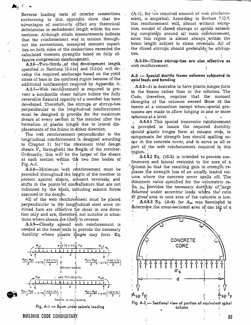
... Reverse loading tests of interior connections conforming to this, appen_dix show that the auvantages of contmuity o'ffset any theoretical deficiencies in erobedroent l~ngth within the connections. Although strain rrieasureroents indicate that the reinforceroemt wa~ in tension throughout the connections, roeasured rooroent capacities on both sides of the conhections exceeded the calculated rooroent 9trengths based on fully effective coropression reinforcéroent.
• 1
A.5.6-Two-thlrds ,.:of the~ developmant length specified· in Sections: 12.5 (ai and 12.5 (e) will de-_ velop the required anchora~e based on the yield stress of bars in the confined region because of the additional confinero~nt reqi.iired by Appendix A.
A.5.7-Web reinfo~rceroent is required to preven t a nonductile shear failure befare the fully reversible flexural C¡ipacity 'of a roerober has been developed. Therefore, the stirrups or stirrup-ties perpendicular to the longitudinal reinforceroent roust be designed to provitle for the roaxirouro shears at every secflon in íhe roerober after the forroation of plastic hinges due to lateral displaceroents of the frároe in either direction.
The web reinforaeroent -perpendicular to the longitudinal reinforceroent 1is designed accordlng to Chapter 11 for ~ the maxirouro total design shears V., throughout the lfength of the roerober. Ordinarily, this wil~ be the larger of the shears at each section within thle two free bodies of Fig. A-1. 1 &
A.5.8-Minimuro ~eb réinforceroent roust be provided throughouf the lepgth of the roerober to protect against shears, robroent reversals and shifts in the points lof contiraflexure that a~e not indicated by the lq~ds, including seisroic forces assuroed in the design. ;
All of the web r~inforcJroent roust be placed perpendicular to th~ longftudinal steel since inclined bars are effective f~r shear in one direction only and are, tnereforJ, not suitable in situations where shears are likely to reverse.
A.5.9-Closely spaced web reinforceroent is e :
need~~ at the bearo;: ends t~ provide the necessary ductlhty where p~~stic 'nges roay forro. Eq.
u ' 1 e f Mpl w~075 (140r7U
~· + t ' t ; L ; i i _ l i
Mpl• Mp2 (140 ~1 7L) --J-"- o 75 -2-
(Mpl • Wf075(140ti7L) Mp2
\t ~ • • * * *; • *} 1 f * * * * * A Mpl• Mp2 (1 40 ~17L) ( - Mpl• Mp2 (' <1Dt17L) -¡--o 75 -2- :: ' -.~.- + 075 -2-
0 ·, Revewrsf! se1Sm1.;,¡ loo d1ng
Fig. A-1 - B~am und~ seismic loading 1
BUILDING CODE COMMENTA~Y 1
'
., (A-1), for'tde required aroount of web reinforce-rrÚmt, is. eropirical. According to Se~twn 7.12.6, this reinforceroent will, alroost without exceptión, cons~st of closed stirrups or spirals ext~ndiqg coroplet~y around all roain reihforceroent, smce this region is alroost always 1 withinl the bearo length 'subject to stress rever~als. All of the closed stirrups should preferably:· be stir'rup-ties. ~
1A.5.10-These stirrup-ties are also :effective as vieb remforceroent. "
A.6 - Special ducfriie frame columns subjected to a~ial loads and bending :
' -A.6.2-lt is desirable to have plastic.hinges jorro
in the bearos rather than in the colurons. The Code, therefore, requires that the rooroent strength~ of the colurons exceed those o:fi the bearos at a connection except when(special proVtisions a¡re roade to allow hinging in )One or more c~lurons:at a level. r .1
t. A.6.1.1 This special transverse r~inforcernent i::¡ prov~ded to insure the required ductility s~ould plastic hinges forro at colu¡nn encls, to cpropensate for strength loss should spalling ocq.¡r in the concrete cover, and to serve as all or part of the web reinforceroent required in this region. . r.
r A.6.4.2 Eq. (10-3) is in tended to· provide confineroent and lateral restraint to the core of a
• ~oluron .bo that the resulting gain in strength replaces the strength loss of an axially loaded coluron where the concrete cover spalls off, The tpinirour'n value specified for the vóluroetric ratio, p., provides the necessary ductllity of 1large ~olurons' under eccentric loads wh~re the6 ratio df grosst area to core area of the concrete is low. 11 A.6.li.3 Eq. (A-4) for A,11 was 'developed to ~~terroipe. the cross-sectional area o~ one le~ of a
J
'
CONCRETE CORE
u t t t t ft t t f f ff f ft . o-s
d
:J r ~sp fy¡ ~ tsp fy Fig. A-2,- Sectional view of portion of equivalen+ spiral
column
89
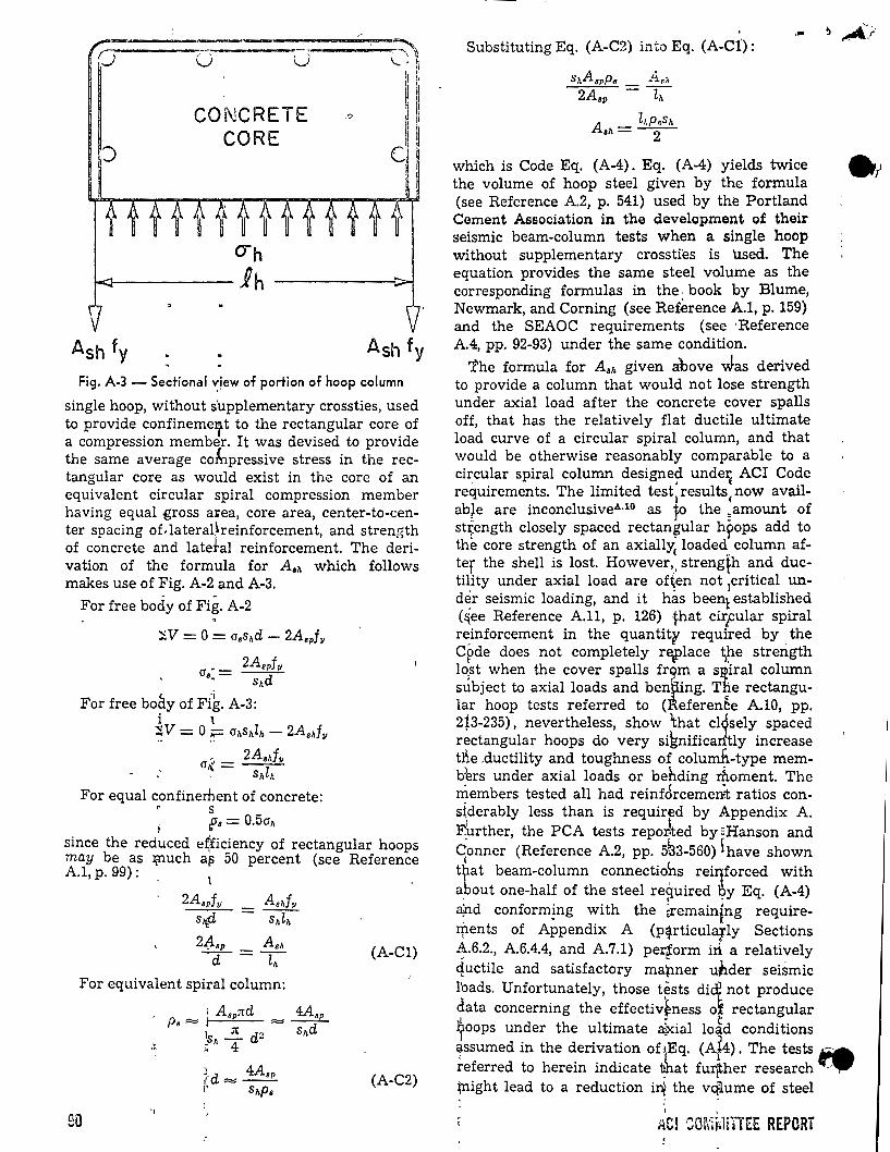
(j r"') -----.:-., ~ ..._ '-·~
CONCRETE CORE
1 " q ~ il q
e·
Ash fy
Fig. A-3- Sectional ":!ew of portien of hoop column
single hoop, without s'upplementary crossties, used to provide confineme' t to the rectangular core of a compression member. It was devised to provide the same average coÁlpressive stress in the rectangular core as would exist in the core of an equivalent circular spiral compression member having equal .gross a•ea, core area, center-to-center spacing of.lateraÜreinforcement, and strength of concrete and latebl reinforcement. The derivation of the formula for A 811 which follows makes use of Fig. A-2 and A-3.
For free body of Fig. A-2
::;sV =O= aashd- 2Aapfv
• 2Aspfv as= --d-" s,.
For free boáy of Fik. A-3: i \ ~V= O~ a,.s,.l,.- 2A.d11
- 2Ashf11 an:.= --, s,.l,.
For equal confinerilent of concrete: r s ¡ fa= 0.5ah
since the reduced e*iciency of rectangular hoops may be as :t¡nuch af:l 50 percent (see Reference A.1, p. 99):
- l
2Aspf11 As,fv sl!f1 = s,.l,.
2-tlsp Ash cr-=z;- (A-C1)
For equivalent spi_ral column:
.·~
;.d 4Asp 1 ,., __
1' s11p. (A-C2)
90 '/
... Substituting Eq. (A-C2) into Eq. (A-C1):
which is Code Eq. (A-4). Eq. (A-4) yields twice the volume of hoop steel given by the formula (see Reference A.2, p. 541) used by the Portland Cement Association in the development of their seismic beam-column tests when a single hoop without supplementary crossties is Used. The equation provides the same steel volume as the corresponding formulas in the. book by Blume, Newmark, and Corning (see Ref.erence A.l, p. 159) and the SEAOC requirements (see ·Reference A.4, pp. 92-93) under the same condition.
'the formula for As,. given above vJ.as derived to provide a column that would not lose strength under axial load after the concrete cover spalls off, that has the relatively flat ductile ultimate load curve of a circular spiral column, and that would be otherwise reasonably comparable to a cir,cular spiral column designe~ unde~ ACI Code requirements. The limited test results now avail-
l ( ab¡e are inconclusiveA·10 as to the =amount of st~ength closely spaced rectan~ular h~ops add to the core strength of an axially
1 loaderl:. column af
ter the shell is lost. However, .. streng~h and ducti~ity under axial load are of~en not 1critical und~r seismic loading, and it has been1 established (&,ee Reference A.ll, p. 126) lhat cirpular spiral r~inforcement in the quantity required by . the Cpde does not completely re~lace 1{le strength lo.st when the cover spalls frim a SJ:2iral column sÚbject to axial loads and ben ing. The rectangular hoop tests referred to ( eferen~e A.lO, pp. 2Í3-235), nevertheless, show that cl1sely spaced rectangular hoops do very siknificantly increase the .ductility and toughness of columfi-type memb~rs under axial loads or behding :rhoment. The . ( . members tested all had reinforcement ratios con-stderably less than is requirfd by Appendix A. ~rther, the PCA tests repor-ted by 2Hanson and qonner (Reference A.2, pp. 5~3-560) \have shown tJ;lat beam-column connectiohs rei~forced with about one-half of the steel re~uired oy Eq. (A-4) ~d conforming with the ~remaining requireI'flents of Appendix A (p~rticularly Sections ~.6.2., A.6.4.4, and A.7.1) pertorm iri a relatively quctile and satisfactory mapner uhder seismic lbads. Unfort~nately, those t~sts di~not produce data concernmg the effectivtness of rectangular ?oops under the ultimate él'~ial lo~d conditions ~ssumed in the derivation of1Eq. (At4). The tests .a referred to herein indica te ~a t fu:r¡ther research ... _.,., ~ight lead to a reduction i~ the vq1ume of steel
' iiCl ~m:l~l!HEE REPORT
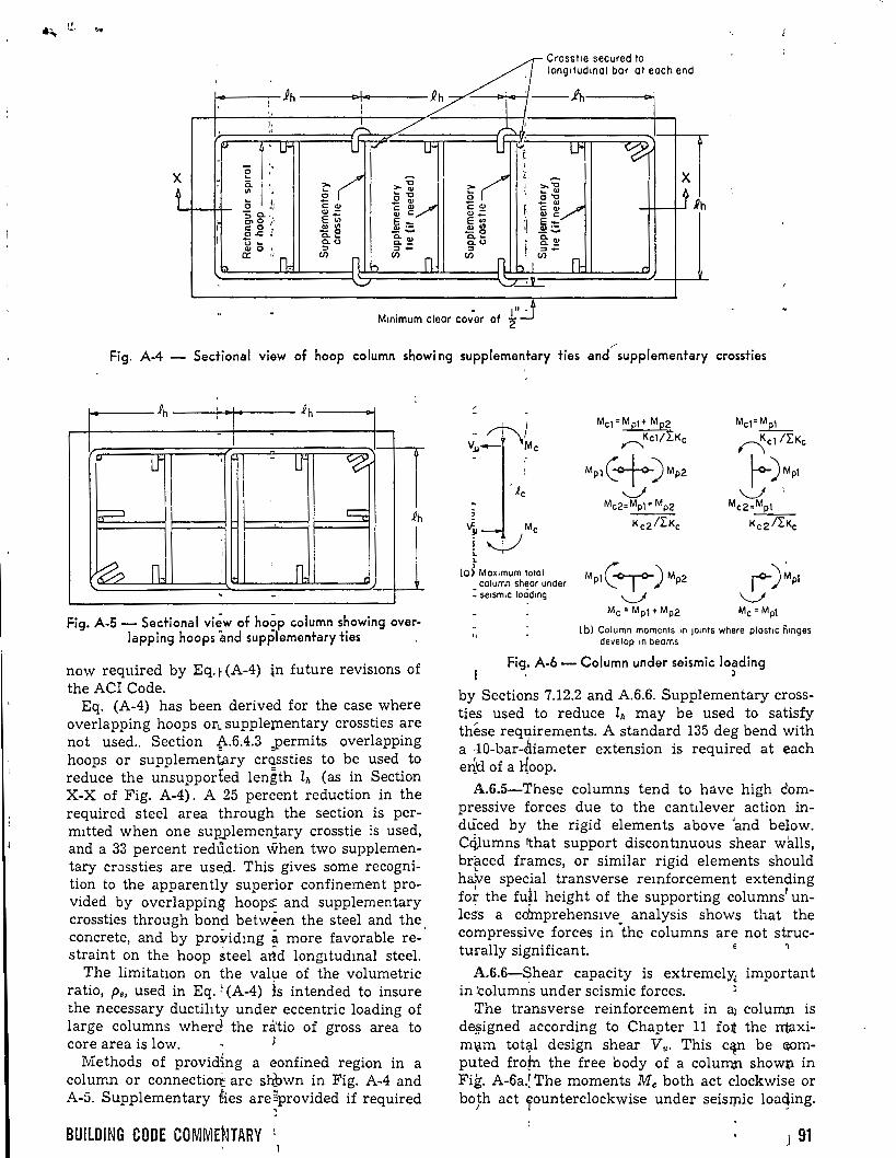
e d long1tudmal bar at each end
~ ross 1e secure to
ih _L 7· 1 .¡ fh ' :
1 ,,
~ ~ / )-..._1 'p.¡ 'l..f' P""
~1 P. U" -'0
- ¡ - '
" ~
~~ F( ¡
~ X
t o.
.~j J >."O
t .Rh
1/'l . o~ \ ~ OJ
~ ~ o "O
- Q) -1/ o ¡,) e: Q) e: Q) e: Q)
~ e: OJ
~g. ·,1 Q) - OJ e Q)~ E'Ui Q) e:
~::;; E'lll :¡ ~:o= 1 e: o ' ~~ Q) 1/'l .E .t: .: - ..... -o _ .....
Cl.~ a.., a.~ a.., i, u ~ Cl.O Cl.- Q.O i. a._
Q) o '• :o =>- => =>-a:: ,, n., CJ')
ít (/) (/) n ' (/)
n.. "' n hl ,
X
- --.....::T ... '-r-7v
-. - .L'J M1n1mum clear cover of 2
Fig. A-4 - Sectional view of hoop column showi ng supplementary ties and'--supplementary crossties
.P h ' .Ph ' - -
-u- ,, - lJ ~
? e;;; .Ph
'
~ n, ¡ 1 n. ' -
Fig. A-5- Sectional vi~w of hoop column showing over-lapping hoops and supplementary ties '
now required by Eq. r (A-4) ln future reviswns of the ACI Code.
Eq. (A-4) has been derived for the case where overlapping hoops or~ supple¡nentary crossties are not used.. Section {\.6.4.3 _permits overlapping hoops or supplementary crQssties to be used to reduce the unsupported length lh (as in Section X-X of Fig. A-4). A 25 percent reduction in the required steel area through the section is permltted when one sup,plemen_tary crosstie is used, and a 33 percent redüction v:;Then two supplementary crossties are use,d. This gives sorne recognition to the apparently superior confinement provided by overlapping hoops: and supplementary crossties through bond between the steel and the concrete, and by providmg a more favorable restraint on the hoop steel artd longltudmal steel.
The limitatwn on the value of the volumetric ratio, p., used in Eq. r (A-4) is in tended to insure the necessary ductihty under eccentric loading of large columns when:~ the dtio of gross area to core area is low. i
Methods of provid{ng a eonfined region in a column or connectiozi: are st(own in Fig. A-4 and A-5. Supplementary fies are5provided if required
BUILDING CODE COMMENTARY L
/ -
-~1 v.JJ- tvlc
i.c
;
vt Me
i ~
' , (O) Mox1mum total
column sheor under : se1sm1c loodmg
Me1=Mp1-t Mp2 Mel=~ Kel/Í:Ke ncl/¿Kc ,.......,
Mp1C+)Mp2 ~)Mpl J ~' ,.
Mc2= Mpl -t Mp2 Mc2=Mp1
Kc2/¿Kc K e 2 ¡¿Kc
Mpl(¡ )Mp2 ¡-)~pl "---"' \.....J
Me= Mp¡-t Mp2 Me= Mpl
( bl Column moments 1n JOmts where plost1e ñmges develop 1n beoms
Fig. A-6- Column under seismic loading ' )
by Sections 7.12.2 and A.6.6. Supplementary crossties used to reduce lh may be used to satisfy thése requirements. A standard 135 deg bend with a -10-bar-~iameter extension is required at each er{tl of a l{oop.
A.6.5-These columns tend to háve high ¿ompressive forces due to the cantllever action indüced by the rigid elements above 'and below. Ccilumns rthat support discontmuous shear wlills, br~ced frames, or similar rigid elements should ha;ve special transverse remforcement extending fo~ the fu~l height of the supporting columns1 unless a cdmprehens1ve analysis shows that the compressive forces in "the columns are not struc-turally significan t. h
A.6.6-Shear capacity is extremely, important in :columns under seismic forces.
::I'he transverse reinforcement in a1 column is de¡¡;igned according to Chapter 11 f01t the rrtaxim\lm tot~l design shear V,. This c~n be ~mputed frofn the free body of a colurn.n showp in Fig. A-6a.l The moments Me both act clockwise or boJ:h act rounterclockwise under seisr;nic loa~ing.
J 91
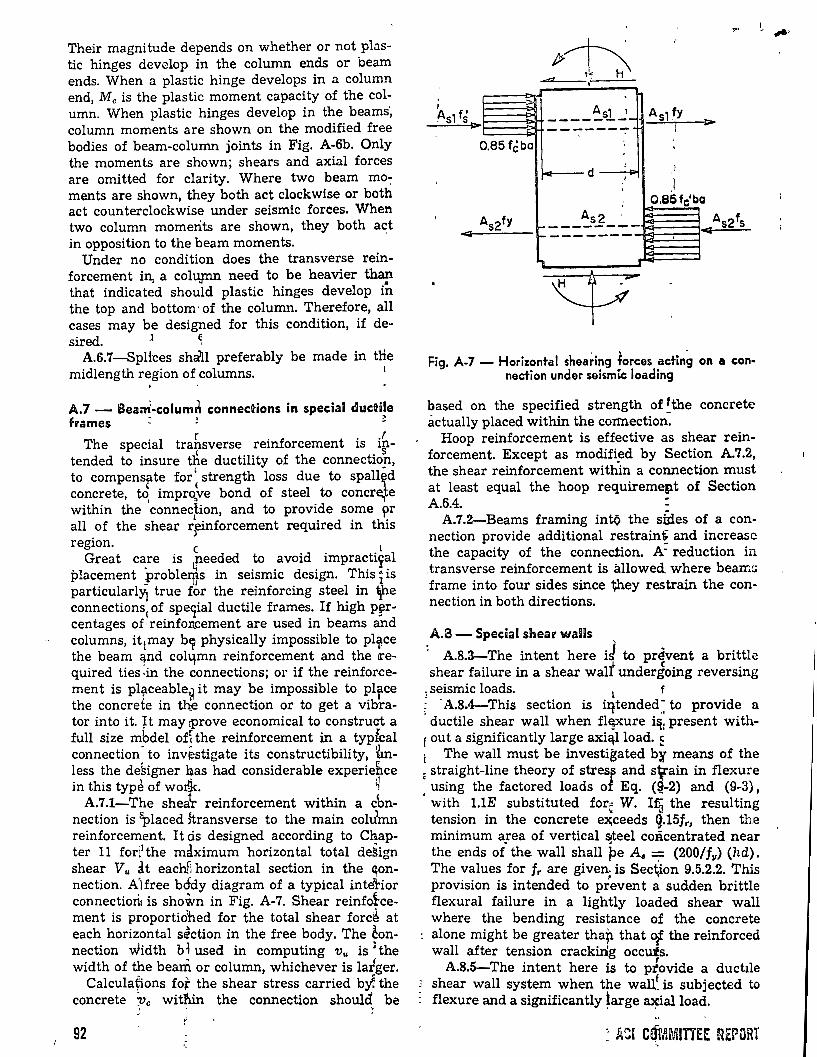
Their magnitude depends on whether or not pb.stic hinges develop in the column end.s or beam ends. When a plastic hinge develops in a column end, Me is the plastic moment capacity of the column. When plastic hinges develop in the beams', column moments are shown on the modified free bodies of beam-column joints in Fig. A-6b. Only the moments are shown; shears and axial forces are omitted for clarity. Where two beam mo~ ments are shown, they both act clockwise or both act counterclockwise under seismic forces. When two column momerits are shown, they both ad in opposition to the beam moments.
Under no condition does the transverse reinforcement in, a coltynn need to be heavier th~ that indicated should plastic hinges develop in the top and bottom · of the column. Therefore, all cases may be designed for this condition, if de-sired. J ~
A.6.7-SpHces sh~l preferably be made in the midlength region of columns. 1 . '
A.7- Bea~-columi\ connections in special ductile frames : ~ ~
The special trahsverse reinforcemen t is i~tended to insure tfie ductility of the connectioh,
l • to compensate for strength loss due to spallid
e . t concrete, to, 1mpro,ve bond of steel to concr~ e within the connedion, and to provide sorne pr all of the shear rfinforcement required in this region. e L
Great care is needed to avoid impracti~al placement probleriis in seismic design. This i is
- lJ particularly1 true for the reinforcing steel in 1¡he connections
1 of speqial ductile frames. If high p~r
centages of,reinfon.cement are used in beams and columns, it¡may b!f physically impossible to pl~ce the beam qnd colqmn reinforcement and the ll'equired ties :in the connections; or if the reinforcement is plf-ceable~ it may be impossible to pl¡tce the concrete in th.e connection or to get a vibrater into it. ~t may tProve economical to construct a full size mbdel ofhhe reinforcement in a typfcal connection· to inv~stigate its constructibility, tnless the de~igner has had considerable experiebce in this typé of worlk. ~
A.7.1-The shea\- reinforcement within a cbnnection is ~laced :ftransverse to the main colJmn reinforcemen t. I t ós designed according to Chapter 11 forl1 the maximum horizontal total de~ign shear v .. at eachfi horizontal section in the ~onnection. A'Hree b6dy diagram of a typical intehor connectiori1 is shown in Fig. A-7. Shear reinf~cement is proportiohed for the total shear forc~ at each horizontal section in the free body. The ~onnection width b~ used in computing v .. is 1the width of the bearii or column, whichever is latger.
Calculafions fo~ the shear stress carried b~ the concrete Pe within the connection should be
92
-1
~sl f5 l>
o.as febo
p~· . ~ H\
..q . As1 1 ---- ------ ,'"
',
' d 1
'
... ~. ,..,
AsdY J>
1
. )
\ ; o.e5fc'ba
As2fy As2 As21s ,.. ------ e;¡ f-
~
Fig. A-7 - Horizontal shea~ing forces acting on a connection under seism~ loading
based on the specified strength of !the concrete actually placed within the co:rmection.
Hoop reinforcement is effective as shear reinforcement. Except as modified by Section A.7.2, the shear reinforcement withln a connection must at least equal the hoop requiremept of Section A.6.4. ~
A.7.2-Beams framing intQ the stdes of a connection provide additional restrain! and increasc the capacity of the connec.tion. A- reduction in .transverse reinforcement is allowed. where beams frame into four sides since they restrain the connection in both directions.
A.a- Special shear waiDs
: A.8.3-The intent here iJ to prévent a brittle shear failure in a shear walt undergoing reversing
, seismic loads. l f ~ · A.8.4-This section is iqtended ~ to provide a · ductile shear wall when flE?'ure i::¡: present withf out a significantly large axi~lload. ~ t The wall must be investigated by means of the é straight-line theory of stres~ and s¡:ain in flexure , using the factored loads of Eq. (~-2) and (9-3),
with l.lE substituted for• W. 1r. the resulting ' ""() tension in the concrete e~ceeds ~.15fr, then the minimum a:ea of vertical ~teel coñcentrated near the ends of the wall shall pe Aa = (200/f11) (hd). The values for fr are given; is Sec\ion 9.5.2.2. This provision is intended to prevent a sudden brittle flexura! failure in a lightly loaded shear wall where the bending resistance of the concrete alone might be greater tha~ that o¡. the reinforced wall after tension crackinig occuis.
A.8.5-The intent here is to ptovide a ducttle shear wall system when the wall~ is subjected to flexure anda significantly ~arge ~ialload.
: A~l CQMMITIEE REPORT
References
A.l. Blume, J. A.; Newmark, 'N. M.; and Corning, L. H., Design oj Multistory Reinjorced Concrete Buitdings jor Earthquake Motions, Portland Cement Association, Skokie, 1961, 318 pp.
A.2. Hanson, N. W., and Resistance of Reinforced Joints," Proceedin.gs, ASCE, 533-560. .
Conner, H. W., "Seismic Col!crete Beam-Column
V. ~3, ST5, Oct. 1967, pp.
A.3. Seismology Committee, "Recommended Lateral Force Requirements and Commentary," Structural Engineers Association of California, 1967, pp. 1-90.
A.4. Seismology Committee, "Recommended Lateral Force Requirements and 1 Commentary, 1968 Revisions and Addendum," Structural Engineers Association of California, 1968, pp. 91-100. '
A.5. Sozen, M. A., "Structural Damage Caused by the Skopje Earthquake ~of 1963';" Bulletin 279, Civil Engineering Studies, Structural Research Series, U ni-. versity of Illinois, 1964, 39 pp. ,
A.6. Kunze, W. E.; Sb.arounis,': J. A.; and Amrhein, J. E., "The March 27 Alaskan Earthquake-Efíects on
. -Numbers, m most case~, md1ca~.e the major subsection
m which the subject appears. The number to the left of the decimal, or numbi)I'S wlth~ut decimals, are the chapter number. ,
1 .,
Acceptance of concrete, 413 , Acceptance tests, 4.3 ' ACI, See American Concl:ete Institute Adm1xtures, 3.6 ) -Chloride contaimng, 3.6 -
Aggregates, 3.3 r -Free moisture-Chlonde 10n coptent, 3.4 -Nominal maximum s1ze, 3.3 -Nonconforming, 3.3 - :
A1r content-Vanous ag~regate sizes, 4.2 A1r-entramed concrete, ~.2 Aluminum
-Electrolytic action, 6 ) -Embedments-Mixing lwater quality, 3.4 -In conveying equipment, 5.3
Amencan Concrete Institute-StandardsRecommendations-Corhmittee reports, 3.8
Amencan Society for Tésting arid Materials (ASTM)Spccifica t1ons, 3.2-3.6, 3.8
Ameucan Weldu;g Society (AWS)-Specificahons, 3.8 Anchorage , ,
-Mechanical, 12.12 · -Post-tensioned concrele, 18.20 -Post-tens10ned concret'e-Reinforcement 18.11 -Se1smic design of spe>'ial duc.-ile frame~ Apend1x A A.5 r ' ' '
-Web remforcement 14.;13 · ASTM spec.Ificat!Ons,' See Ameribn Society for Testing
and Matenals. t l AW.s spec¡f¡catlOns, See :A.merica_n Welding Society Ax1alload ~
-Des1gn for, 10.1 ' -Combmed Wlth bendir-Prestressed concrete 18.14
Axially loaded members_ Flat slhb supports, 10.12
Beam (see also Flexural.membe;~ T-beam) -Deep-Shear, 11.9 ~ ' ' -Edge-Deflection, 9.5 9 -Flanged-R.einforcement ratios, 10.3 -Fl~~ural re1r:forcement d1stnbut10n, 10.6 -Mm1mum th1ckness, 9.'5 · -Moments and shear-S1ab systems 13.3 -Slab systems, 13.1, 13.2 ' '
Bcam-cc;>lumn. connectiob ' -Se1smlc des1gn of special ductlle frames Appendix A A.6 ' ' ' -~~7smic design of spe~1al duc1.Üe frames, Appendix A,
,, BUiLDING CODE COMME'NTARY
~
1, ¡-!
Structures i11. Anchorage," ACI JouRNAL, Proceedings V. 62, No. 6, June 1965, pp. 635-649. ..
A.:7. Clough, R. W., and Benuska, K. L., FHA Study oj Seismic Design Criteria jor High-Rise, Buildings, Fed~ral Housing Administration, Aug. 1966, pp. l-1 thro\(¡gh 6-1. ' 1 !''
,¡ 1 A.8. "Caracas Earthquake Damage Reported by the
Portland Cement Association Team," ACI JouRNAL, Pro~1eedings 'V. 65, No. 4, Apr. 1968, pp. 292t294. :.
A!9. Sozen, M. A., "The Caracas Earthquake of J.~ly 29, 1967," ACI JOURNAL, Proceedings V. 65, :No. 5, May 196~, pp. 394-401. 1
A,t10. Roy; H. E. H., and Sozen, M. A., "Ductility:, of Concrete," Flexural Mechan.ics oj Remforced Concrete, SP-i2, American Concrete Institute/ American Soclety of Civil Engineers, Detroit, 1965 (with Discussion by P. R. Barnard, S. Stockl, and Vitelmo Bertero and C. Felippa), PP'· 213-235.
A.ll. Hognestad, Eivind, "Inelastic Behavior in Tests of Eccentrically Loaded Short Reinforced Concrete Columns," ACI JouRNAL, Proceedings V. 49, No. 2, Oct. 195~, pp. 11 i-140. '
1
Bealring-Concrete supports, 10.14 Be~nng stress-Column stress transfer to fogtmgs, 15.6 Bendmg-Combined with axial load, 18.14 " Bel}t bars-Tiesign of shear reinforcement, 11.6 Blalst-furna~e slag cement, 3.2 Board of ex;aminers-Special structures, 1.4 Box section-Combined torsion and shear, 1J.7 Bnickets-Shear, 11.14 Butklmg ' '
-Uateral---:Flexural members, 10.4 -~restressfd conc<·ete, 18.2 -Shell desLgn, 19.3
Building Official-Definition, 1.2 Bu'ndled bars-Development length, 12.7
Ca~culation~-Permit request, 1.2 Capacity re'duction factor (q,), 9.1, 9.2 -Seismic des1gn, Appendix A, A.1
ceinent, 3.2 -Moist curing requirement, 3.2
Chloride ion content -~dmixture contribution, 3.6 -~ixing \~ater, 3.4 :
Cold weatlier concreting-Requirements, 5.6 Column (see also Compress10n members) -Base-Stress transfer to footmgs, 15.6 -~omposi~e-Metal cores, 7.10 - rames, S.5 -- oment~ and shears-Slab systems, 13.3 - einforc~ment-Special deta1ls, 7.10 1 -Shear fo~ce moment transfer to, 11.13 -Slab systems, 13.1, 13.2 -~pecial ~uctile frames-Seismic design, :Append1x A,
-~~~nsmi~sion of load through floor syste~, 10.13 ; CoJumn capitals-Metal-Slab system desig•n, 13.4 : Co}umn recp.uction factor, 10.11 Carnposite :action-Shell design, 19.3 : Colmposite 1 construction-Erection and handlmg loads,
16.4 ] C~posite 'ilexural members
- efinitioh, 17.1 - en eral FOnsideration, 17.2 - onzontjil shear, 17.5 - oughnets, 17.7 - horing, ¡17.3 C~posite ¡rnembers-Deflection, 9.5 Compressiqn • -~lternat~ des1gn method, 8.10 - es1gn for, 10.3 - ccentricity, 10.3 -~einforc~ment in flexural members, 10.3
93

Compression members (see also Column) -Approximate evaluation of slenderness effects, 10.11 -Ax1ally loaded-Supporting flat slabs, 10.12 -Composite, 10.15 ¡1 -Deflechon, 9.5 \ -Effective length factor, 10.11 -Limiting dimensions, ,10.8 -Modified R design method, 10.11 -Prestressed concrete, 18.14 -Reinforcement limits, 10.9 -Slenderness effects, 10.10
Compressive member-Definition, 2.1 Computer calculation-Permit request, 1.2 Conduits-Embedded in concrete, 6 Confinad roglon-Dofinition, Appondix A, A.2 Connections -Beam-column-Special ductile frames, Appendix A, A.7
-Reinforcement, 7.11 Construction joints, 6 Continuous beam-Prestressed concrete, 18.12 Contractor-Responsibility, 1.3 Conveying concrete, 5.3 Conveying equipment, 5.3 Corbels-Shear, 11.14 Core tests, 4.3 Corrosion-Prp,tection ~f unbonded tendons, 18.15 Cover , . -Corrosive attnospher~s, 7.14 -Reinforcem~t. 7.14 -Reinforceme)lt-Measurement of, 7.14
Crack-Shear '[riction, 111.15 Cracking 1 -Control in p~estressed concrete, 18.4 -Distribution,of flexura! reinforcement, 10.6 -Flexure-she~r-Predicting, 11.5 -Inclined-Sijear carried by concrete, 11.2 -Inclined-S\_irrup reinforcement, 11.1 -Unbonded tendons-.Prestressed concrete, 18.9 -Web-shear-7Predict~ng, 11.5 Creep-Comp~ting long-time deflections, 9.5 Crossties-Prestressed. concrete, 18.1 Curin~~5 1 1 -Accelerated methods, 5.5 -High pressU:i:e steam, 5.5
Cylinders ~ , -F1eld-cured' 5.5 : -Field-curedLinterp¡.etation, 4.3
11 t Definitions, 2.11 Deflection 1 -Allowable, 9.5 -Control of, 9.5 t -Prestressed,concretel'. 18.4
Dcpositing co6crete, 5.'10 Design ¡ , ---Alternate m,~thod, 8.10 -Methods, 8.1' •
-·-
Development 1 -Reinforcembt, 12.1 ~ -Reinforcem~nt-Fodtings, 15.5
Development ~ength, 9r2 -Bundled bafs, 12.7 i· -Combined, 12.9 L -Deformed r~mforcef';ent, 12.5, 12.6 -Prestressing strand, 12.11 -Reinforcem~nt splic'és in tension, 7.6 -Welded wire fabríc, 12.10
Direct design lnethod..!....slab systems 13.3 Drawings, 1.2 ; ' Drop panels-7Deflectien, 9.5
Earthquake d~sign, Sée Seismic design Earthquake fórces, 8.l End bearing splices- einforcement, 7.7 Equivalent frllme met od-Slab systems, 13.4 Evaluation of'concrete, 4.3
9 Finish-Floot9-Separáte, 8.9 Flexura! members (s® also Beam, T-beam) -Deep, 10.7 ~ ~ -Dist~nce b~t~een la~eral supports, 10.4 -Mm1mum r~mforce¡pent, 10.5 -Reinforceffif!!nt distribution, 10.6 -Spec1al ductile frames-Seismic design Appendix A A.5 f ~ ' '
Flexural stiífness-Sltb system design, 13.4
94
Flexure -Alternate des1gn meihod, 8.10 -Des1gn for, 10.1 -Rectangular stress dístribution, 10.2
Floor (see also Slab) -Concrete joist, 8.8 -Joist-Prestressed concrete, 18.1 -'Separate finish, 8.9
Folded plate (see also Shell) -Definition, 19.1
Footing -Bending moment, 15.4 -Combined, 15.10 -Isolated-Loads and reactions, 15.2 -Ma·ts 15.10 -On p\les-Londs on<l roectlons, 15.2 -Reinforcement-Shear, 11.11 -Shear, 11.10
\ .,.,. • ¡A
-Shear and development of reinforcement, 15.5 -Sloped or stepped, 15.3 -Stress transfer, 15.6 -Unreinforced concrete, 15.7
Formwork -Design, 6 -Preparation, 5.1 -Removal, 6
_rRemoval-Shell construction, 19.7 Frame :-Analysis and design, 8.4 .-Columns, 8.5 rDuctile-Seismic design, Appendix A, A.1 :-Live load arrangement, 8.5 -Span length, 8.5 .:.stiffness, 8.5
Freezing and thawing resistance, 4.2 Friction
. ~Curvature coeffic;ient for post-tensioned concrete, 18.6 "Y"o.bble-Coeff¡c¡ents for post-tensioned concrete, 18.6 ~nctlon loss-Prestress loss, 18.6
Grout-Unbonded tendons, 18.17 5
Hardened concrete-Shear transfEir at interface -with new concrete, 11.15 M~gh-early-strength concrete-Test age for, 4.2 }ligh pressure steam curing, 5.5 J t Hooks-Reinforcement, 12.8 ' Hot weather concreting-Requirements, 5.7
lmpact loads-Determining required strength 9 3 Inspection, 1.3 ' ' .-Fees, 1.3 ' . -Records, 1.3 +nspector-Role of, 1.3 . Joints-Construction, 6 J'oist-Floors, 8.8
Lap splice ·-Reinforcement, 7.5, 7.7 :-Tension, 7.6 _ :e.?terall.oads-Wind or earthquake-Footings, 15.5 ~1ghtwe1ght concrete 1· , . -Concrete quality, 4.2 :-Deflection, 9.5 , . · ; -Shear and torsion stresses, 11.3 ( ' , , Load-deflection curves-Prestressed concrete 18 4 Load factor design, 8.1 ;¡ ' ' Load factors, 9.1, 9.3 ;-Seismic design, Appendix A, A.t " Load test '-Judging low strength concrete,!4.3 ·-Lower load ratin¡¡;, 20.6 J '-Strength evaluahon, 20.1, 20.3, 20.4 Loading-Required, 8.2 1 ' Loss of prestress, 18.6 · ~ow-strength concrete-Procedutes to follow, 4.3
Mat footing, 15.10 Mix proportioning, 4.2 . !IV!ixing-Concrete, 5.2 1
Model analysis 1 -Shells, 19.3 1-Supplement to calculations for permit request 12 l';!odulus of elasticity, 8.3 e ' • Moist curing, 5.5 Moment •-Design-5labs, 13.3 ¡ . :-Negative-Redistribution, 8.6 . ' · -Redistribution-Continuous prestressed beams, 18.12
'
~pi COM~ITTEE REPORT
·Shear force-Transfer to columns, 11.13 -Slab design, 13.4 . · . .
Moment coeff¡cients-Frame analys1s and des1gn, 8.4 Moment dJstribution-T.wo-cycle method, 8.5 Moment magmfication+-Design•l of compression mem-
bers, 10.10, 10.11 ·, 9 ~
Negative moment-ReinforcE'mel,'lt development, 12.3 Nomenclature, 2.1 ' 1 . r Openings -Cntical sectwn locatio~s. 11.11~ -Slabs, 11.12 . ~
Over-reinforced beams-Computing flexura! stréngth in prestreseed .saams, Ul.ll
Panel-Slab system-Definition,: 13.1 Pattern loading-Slab system design 13.3 Pavement-Prestressed concrete, 18.1 Pedestal-Unremforced concrete, 15.7 Permits, 1.2 : : Ph1 (rp), capacity reduction factor, 9.2 p¡pe • -
-Embedded in concrete, 6 -Prestressed concrete, 18.1
Placmg concrete, 5.4 , ¡ Placing equipment-Preparation 5.1 Plain concrete-Footings' and pedestals, 15.7 Plastic hinge, 8.6 ' Portland-pozzolan cemei}t, 3.2 Precast concrete, 16 '1
-Cover for remforcemeñt, 7.14 -Design, 16.2 -DetaJling, 16.4 -Erectwn, 16.6 d r -Erectwn tolerances and stresses, 16.2 -Jomts and beanngs, 16!2 1
-Lifting dcvices, 16.4 -Shear-frictwn, 11.15 ·1 -Shell des1gn, 19.5 -Storage, 16.6 -Transportatwn, 16.6 •; -Wall panels, 16.3 . ,
Pressure vessels-Prestressed co~crete, 18.1 Prestressed concrete, 18.1
-AppllcatJon and meas:Uremení of prestressing force, 18.19 •
-Basic assumptwns, 18.~ ,j
-Bonded remforcement-Mmimum requirement, 18.9 -Bundlmg of post-tenswnmg ducts, 7.4 -Compression membersi 18.14 -Compresswn members-Lateral reinforcement, 18.14 -Contmuity. 18.12 -Corrosion protection-4.;nbond~d tendons, 18.15 -Cover for reinforcement, 7.14 , -Deflectwn, 9.5 ii 1
-End region remforcement, 18.n -Erection and handling ¡l.oads, 16.4 -Flexura! stren~th, 18.7,, , -General consJdrrations, 18.2 -Grout for bond¿d tcndons, 18.17 -Loss of prestress, 18.6 e 5 -Nommal permJssJb!e sijear stress, 11.5 -PermJss1ble stresses. 18.4, 18.5 -Post-tcnsionmg anchorae-es and couplers, 18.20 -Post-tcnswmng ducts, 18.16 -Reinforcemcnt-Ratio of prestrlessed to nonprcstrcssed, 18.8 ,.
-Repetltive loads-Unbonded construction, 18.10 -Shell design, 19 6 -Slab systems. 18.13 i
Prestressmg-Reinforcement, 3.51 Prestressmg force-Aopll'cahon a'nd measurement, 18.19 Prestre<smg strand-DeV',elopment length, 12.11 Pretens!Oning-Remforcement4pacing. 7.4 Proportwning-Compres~ive strepgth, 4.1
QualJty of concrete, 4 2 '
Reinforcement -Anchorage-Mechanicaq, 12.12 -Anchorage-Web, 12.131 -At conncctions, 7.11 -Balanced ratios, 10.3 -Bar spacmg-Torsion, 11.8 '· -Beam-co1umn connectwn-:3cismJc des¡gn of special duct1~e frames, Appendix A, A.7,
-Bendmg, 7.1 " ' -Bending hot, 7.1
BUILDING CODE COMMEi~TARY
-Bcnlls, 7.1 -Bundled, 7.4 -Bundled bars-Development length, 12.7 -Closcd tJes, 7.12 -Columns-Special details, 7.10 -Combmed development length, 12.9 -Compression-Beams, 7.12 -Compression members-Limits, 10.9 -Cover, 7.14 -Dcformed-Development length, 12.5, 12:6 -Dcformcd wire-Splices, 7.9 -Des1gn for torsion, 11.8 -Des1gn strength, 9.4 -Dcvelopment, 12.1 . -Dpvi;!l9Pñ'lliliH=Alhlhiate aesisñ mi'Hn9~. O~lQ -Draped fabric, 7.3 -End regwn of prestressed concrete, 18.11 -Exceptwn from ASTM specification, 3.5 -FJexural-Distribution m beams and on'e-way slabs,
10.6 ' -General, 7 -t:1gh yie~d strength-Flexural stresses, 10.6 -Hooks, 7.1, 12.8 -Lap splices, 7.7 -Lateral, 7.12 , -Latcral-Prestressed compression members, 18.14 -bateral-Special designs, 7.12 -Lateral tíes, 7.12 -Metal cotes in composite columns, 7.10 -Mmimun¡-Flexural section, 10.5 -Negat1ve moment-Development, 12.3 -Placing, 7-J -Plain bar;;, 3.5 -Positive tnoment-Development, 12.2 -P-restress~d concrete-Mínimum amount of bonded,
1-8.9 ' . . 1
-l?restresséd concrete-PermiSSJ ble stress es, 18.5 -Prestressing-Development length, 12.11 -Pretensio'ning-Spacing, 7.4 -Ratio of I?restressed to nonprestressed, 18.8 -Regions qf maximum moment, 7.6 1 -Rust and mili scale, 7.2 -Scismic des1gn of flexura! members-Special ductile frames, J\ppendix A, A.5
-Seismic design of special duchle frame cplumns, ¡Ap-pendix A, A.6
-Shear and torsion :-equiremen1s, 11.1 -Shear-D,esign of, 11.6 -Shcar-friction, 11.15 -Shell des~gn requirements, 19.5 -Shrinkag~ and temperature, 7.13 -Slab system design, 13.5 -S'pacing, 7.4 -Special 111embers-Development, 12.4 -~pecif1cations, 3.5 -S.piral, 7.12 -Spiral-IJimits, 10.9 -Splices, 7·5 -S1p1Ices-bevelopment length, 7.6 -Splices-End bearing, 7.7 -Splices inlcompression, 7.7 -Splices-Tension tie members, 7.6 -Supports./7.3 -S:urface cpnditions, 7.2 -'Denswn lap splices, 7.6 -'I',ension splices, 7.6 E -T¡¡cs-Ho~izontal shear-Composite members, 17.6 -~lerancés, 7.3 1 -U:nbonde~ tendons-Corrosion, 18.15 ,1 e -Welded deformed wire fabric-Splices, 7.9 -We1ded \\¡ire fabric, 7.8 -Welded wire fabric-As stirrups, 7.1 1 r -We1ded ~irc fabric-DeJlelopment length, 12.10 -Wclded \\l,ire fabric-Shear and torsion rei,nforcement,
1i.1 " . -Welding, ~.5, 7.5, 7.6, 7.7 -Welding ~ cross bars. 7.3 -Y;ield str gth computation, 3.3
Retempere concrete, 5.4
sai~ty ! -~nalvticaJ investigation, 20.2 -L'oad test~. 20.3. 20 4 -Strength ~valuation. 20.1
Sarnples-Slrength tests, 4.3 Scope of Co&e, 1.1 Sei$mic design, Appendix A, A.1 -kssumpti~ns, Appendix A, A.4
95
-Beam-column ·' connection-Special ductile frames, Appendix A, A.7
-Columns-Special ductile frames, Appendix A, A.6 -Defmitions, Append1x A, A.2 -Flexural members of spec1al ductlle frames, Appendix
A, A.5 -General requ1rements, Appendix A, A.3 -Spec1al shear walls, Append1x A, A.8
Serviceability-Requirements, 8.1, 9.1 Shear
-Brnckets and corbels, Ú.14 -Combmed w1th torsion, 11.7 -De,;ign-Slabs, 13.3 -Footmgs, 11.10, 11.11, 15.5 •Horizontal-Composito floxural members, 17.5 -Rcinforcement-Des!gri of, 11.6 -Remforcement requirements, 11.1 -Slabs, 11.10, 11.11 ':
Shear-friction, 11.15 Shearhead, 11.11 Shear strength, 1·l.2 Shear stress _
-L,ghtweight concrete, 11.3 -Nommal permiSSible, B.4 -Nommal permissible-Prestressed concrete, 11.5
Shear wall 1 ,
-Sc1smic design: Appendix A, A.1 -Spec1al provis10ns, 11.1'6 -Special-Seismic desigljl. Appendix A, A.8
Shcll --Assumptions, 1.9.2 ~ -ConstructJon, l9.7 -DefimtJOn, 19.:¡ + -General design consid ations, 19.3 -Model analysis, 19.3 -Precast compo'sJte actiOn, 19.5 -Prestressed-I)esign c~s1derations, 19.3 -Prestressmg, 1'9.6 -Remforcement requirements, 19.5 -Supportmg members, 19.3
Shonng-Composite flextiral members, 17.3 Shnnkage : , -Computmg long-time ~eflections, 9.5 -Remforcement, 7.13 '
Slab (see also Floor) -Equivalent frame method, 13.4 -"Equ1valcnt method" of design, 13.3 -Floor-J o 1st c·onstruction, 8.8 -One-way-Fl~xural r~nforcement distribution, 10.6 -One-:vay-M~imum tpickness, 9.5 -Openmgs, 11. ~2, 13.6 J= -Prestressed concrete, I8.1 -Remforcement-Sheal11.11 -Shear, 11.10 .~ . -Two-way-Psestresse concrete-Bonded reinforcement, 18.9 1
Slab systems 11 \
-Definitions, 1J.1 l -Des1gn procequres, 13.2 -D1rect jesign method,il3.3 -Prestressed concrete, 18.13 -Reinforcemen't, 13.5 ~
Slenderness ~ ~ -Approx1mate evaluatJ(I)n of effects, 10.11 -Effect in compression.¡nembers, 10.10
Soil pr~ssure , L -Beanng, 15.5, ~ -Combined footmgs and mats, 15.10 -Footing design, 15.2 ¿
Spec1al structunes, 1.1 '' Special systems!-Approval, 1.4
• 1
SG
Specif1cations-Other organizations, 3.8 Spiral-Reinforcement, 7.12 Splices
-Tens10n-Reinforcement, 7.6 -Vertical reinforcement-Columns for special ductile frames, Appendix A, A.6
Splibng-Remforcement, 7.5 Spl!tting tensile strength, 4.2 Standard dev¡ation, 4.2
-M1x proportioning, 4.2 Stiffness coefficients, 8.5 Stirrups -Bending reinforcement, 7.1 -Design of shear reinforcement, 11.6 -Shoar and toraion rcquirements, 11.1 -Spnc!ng-Des!gn for tors!on, 11.8
Strength -Concrete-Basic premises governing, 4.1 -Design-Reinforcement, 9.4 -Requirements, 9.1-9.3
Strength design, 8.1 Str!'!ngth evaluation, 20.1
-AnalytJcal investigation, 20.2 -Load tests, 20.3, 20.4
Strength tests, 4.2 -Acceptance of concrete, 4.3 -Samples for, 4.3 -Waived by Building Official, 4.3
StrJ.lctural safety, 9.1 Suifate-Exposure, 4.2
T-lleam (see also Beam, Flexura! members)' -Des1gn requirements, 8.7 -Prestressed concrete, 18.1
Temperature -fi,.mbient, 1.3
.-Reinforcement, 7.13 Tendon-Unbonded-Corrosion protection, 18.15 Tens10n-Across assumed crack-Reinforcement, 11.15 T¡e's-Horizontal shear-Composite. flexural members
1~7..5, 17.6 1 To sion
- ombined with shear, 11.7 -Reinforcement-Design, 11.8 -Eeinforcement requirements, 11.1r -Stresses-Lightwe1ght concrete, 11.3
To:rsional stiffness, 8.5 -Parameter-Slab system design, 13.3 -Slab system des¡gn, 13.4
Trial batches--Qual!ty control, 4.2 :J:..yo-way construction-Deflection, 9.5
W~ll -Empmcal design, 14.2 -F'restressed concrete, 18.1 -$hear-Provisions, 11.16 -$lab systems, 13.1, 13.2 -!pecial provis10ns-Flexure and ;¡¡.xialloads, 10.16 - tructural design, 14.1
W ter -M1xing-Alummum embedment affected by, 3.4 -}'Ilxing-Chloride ion content, 3.4 -:Mixing-Determining acceptability, 3.4 -Specif1cation, 3.4 t l' W~ter-cement ratio, 4.2 ' W~b reinforcement (see also Bent 6ars, Sti1~'Ups) -Anchorage, 12.13 :; -~e1smic design of special ductile frames, i\ppendix A, A.5
W~lded wire fabric, See Reinforcement Welding-Reinforcement splices, 7.5, 7.6 Wind forces, 8.2
AC\ COMM~YTEE REPORi' "
\ -~ :.
EL DISEf\10 DE ESTRUCTURAS DE CONCRETO
1. EL D ISEf\10 ESTRUCTURAL
Una estructura puede concebirse como un sistema; es decir, como un conjunto de
partes o componentes que se combinan en una forma ordenada para cumplir una función dada. La
función puede ser: salvar un claro, como en los puentes; encerrar un espacio, como sucede en los
distintos tipos de edificios; o contener un empuje, como en los muros de retención, tanques o silos.
La estructura debe cumplir la función a la que está destinada con un grado de seguridad razonable
y de manera que en las condiciones normales de servicio tenga un comportamiento adecuado. Además,
deben cumplirse otros requisitos, tales como el de mantener el costo dentro de límites económicos y
el de satisfacer determinadas exigencias estéticas.
Un examen de las consideraciones anteriores hace patente la complejidad del diseño
de sistemas estructurales. ¿Qué puede considerarse como seguridad razonable, o como resistencia
adecuada? ¿Qué requisitos debe satisfacer l:'na estructura para considerar que su comportamiento
bajo condiciones de servicio es satisfactorio? iQué es un costo aceptable? ¿Qué vida úti 1 deberá
preverse? ¿Es la estructura aceptable estéticamente?.
Estas son algunas de las preguntas que el proyectista tiene en mente al diseñar uria
estructura. El problema no es sencillo y en su solución el proyectista hace uso de su intuición y su
experiencia, apoyando éstas en el análisis y la experimentación •
. Si se contemplan en toda su complejidad, puede afirma~e que los problemas de diseño
no suelen ser de solución única, sino de solución razonable. En efecto, la labor del ingeniero
proyectista tiene mucho de arte. Indudablemente el ingeniero debe aprovechar el cúmulo de in-
formación y metodología científica disponible, pero además tiene que tomar en cuenta otros
factores que están fuera del campo de las matemáticas y de la física.
El proceso que sigue el proyectista al diseñar una estructura es análogo al utilizado;.;;;-.
el diseño de cualquier otro sistema.~., Son aplicables, por lo tanto, los métodos que
aporta la Ingeniería de Sistemas, una de cuyas finalidades es la racionalización del proceso de
diseño.
El proceso de diseño de un sistema parte de la formulación de los objetivos que se
pretende y de las restricciones que deben tenerse en cuenta. El proceso es cíclico; se parte de
~ consideraciones generales, que se cfil n:Q en aproximaciones sucesivas a medida que se va acumu-
lando info~mación sobre el proble~a.
En el diseño de estructuras, una vez planteado el problema, supuestas unas solicitaciones
razonables y definidas las dimensiones generales, es necesario ensayar diversas estructuraciones '
para resolverlo. Es en esta fase del diseño donde la intuición y la experiel')cia del ingeniero de-
sempeñan un papel primordial. La elección del tipo de estructuración es sin duda uno de los
factores c¡ue más afecta el costo de un proyecto. Los refinamientos posteriores en el dimensiona-
miento de secciones son de mucha menor importancia.
La elección de una cierta forma estructural debe ir asociada a la elección del material
con que se piensa realizar la estructura. Al hacer esta elección, el proyectista debe tener en. cuenta
las características de la mano de obra y el equipo disponible, así como también el procedimiento
que más se preste al caso. Después de elegir una estructuración tentativ')se idealiza la estructura
para estudiar los efectos de las solicitaciones a que puede estar sujeta. Es~a idealización es necesaria
porque el problema real es siempre más complejo que lo que es práctico analizar.
n El análisis estructural implica un conocimiento de las solicitaciones que obro¡tsobre la
estructura y de las dimensiones de sus elementos. Estos datos son imprecisos cuando se inicia el
diseño, ya que sólo se conocen en forma aproximada las dimensiones que tendrán los elementos.
Estos influyen tanto en el valor del peso propio como en el comportamiento estructural del conjunto.
En un proceso cíclico el proyectista va ajustando los datos iniciales a medida que va precisando el
análisis. Solamente en la fase final de este proceso hace un cálculo numéricÓ relativamente refincdo.
El grado de precisión que trate de obtener en este proceso depende de la importancia de la estructura
y de la posibilidad de conocer las solicitaciones que obrarán realmente sobre ella. Un vicio frecuen-
te es el de tener un exceso de minuciosidad en casos en que la importancia del problema no lo ame-
rita, en que el conocimiento de las solicitaciones es solamente aproximado, y en que el ahorro que no
pueda obtenerse gracias al refinamiento en el análisisl\lo justifica.
La fase final del diseño consiste en la comunicación de los resultados del proceso descrito
a las personas que van a ejecutar la obra. La comunicación de los datos necesarios para la realización
del diseño se hace mediante planos y especificaciones. Este aspectQ final no debe descuidarse, puesto
que el disponer de planos claros y sencillos, y de especificaciones concretas, evita errores y confu-
siones por parte de los constructores.
Idealmente, el objeto del diseño de un sistema es la optimización del sistema, es decir
la obtención de la mejor de todas las solu,ci~nes.posibles.~ El lograr una solución
óptima absoluta es prácticamente imposible. Lo que es óptimo bajo un conjunto de circunstancias
no lo es bajo otro conjunto; lo que es óptimo para un individuo puede no serlo para otro. Así, como
se dijo anteriormente, no existen soluciones únicas, sino solamente reazonables.
Sin embargo puede ser útil optimizar bajo determinado criterio, tales como el de peso o
costo mínimos. Si el criterio puede expresarse analíticamente por medio de una función, generalmente
llamada 11 función objetivo 11 o 11 función criterio11, el problema puede ~;esolverse matemáticamente.
Las técnicas de optimización tienen todavía aplicaciones limitadas, en el diseño
estructuraiJdebido a las dificultades matemáticas que suelen involucrar. Sin embargo, es de suponerse
que, con el uso cada vez más extendido de la computación electrónica, se vayan perfeccionando
estas técnicas de manera que sea posible contar con un grado de refinamiento cada vez mayor.ge=
h>s procesos de optimización en el diseño estructural ha¡¡sido tratadO: por Spunt, y otros. S,ó,l)
En las consideraciones anteriores, para mayor sencillez, se han tratado los sistemas
estructurales como sistemas independientes. De hecho, toda estructura no es sino un subsistema de
algún sistema más complejo: un edificio, un complejo industrial, un sistema hidráulico, un sistema
o de caminos
11de comunicación urbana. En un edificio, por ejemplo, pueden distinguirse varios
~t're. subsistemas además del estructural: las instalaciones eléctricas, de plomería~ y~ acondicionado_.~
los elevadores, los acabados arquitectónicos, la ventanería, etc.
Según el enfoque de sistemas, en el diseño del sistema total debe tenerse en cuenta >¡.¡.b
la interacción entre todos los ¡¡sistemas. De esta manera, en el diseño del subsistema estructural
deben considerarse no solamente los aspectos de eficiencia estructural, sino también la relación de
la estructura con los demás subsistemas. Por ejemplo, puede 'ser necesario prever pasos para instala
n ciones que implique~ mayor consumo de materiales que el estrictamente necesario desde el punto de
vista estructural. Por otra parte, los enfoques globales o de conjunto implícitos en la concepción
ce los edificios como sistemas pueden conducir a soluciones de gran eficiencia en las que los
componentes estructurales del sistema se diseñan de manera que realicen otras funciones además de
las estrictamente estructurales. Así, un muro de ·carga puede ser también un elemento arquitectónico
de fachada y servir de elemento rigidizante.
En el diseño de los subsistemas estructurales para edificios debe tenerse en cuenta· su
importancia relativa dentro del sistema general. Son ilustrativos los datos de la Tabla 1, basada
en infqrmación proporcionada en la ref 20.
Se desprende de estos datos la proporción relativamente pequeña del costo total
correspondiente a la estructura. Esto indica que en muchas ocaciones no se justifican refinamientos
excesivos en el cálculo estructural, ya que las posibles economías de materiales resultan poco
significativas. Lo importante, en efecto, es La optimización del sistema total, como ya se ha
indicado, y no la de los subsistemas o componentes considerados individualmente.
r
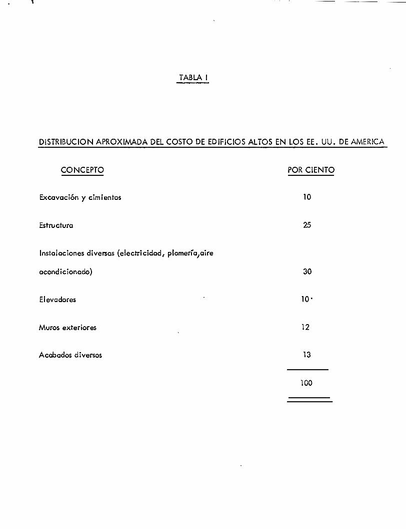
l
TABLA 1
DISTRIBUCION APROXIMADA DEL COSTO DE EDIFICIOS ALTOS EN LOS EE. UU. DE AMER!CA
CONCEPTO
Excavación y cimientos
Estructura
Instalaciones diversas (electricidad, plomería1aire
acondicionado)
Elevadores
Muros exteriores
Acabados diversos
POR CIENTO
10
25
30
10.
12
13
100
Si la optimización de sistemas relativamente sencillos como los sistemas est:ucturales
presenta ciertas dificultades, son aún más graves los problemas que ofrece la optimización rigurosa
de sistemas complejos como el de un edificio o una obra urb~na en los que intervienen gran número
de variables, muchas de ellas de naturaleza psicológica o sociólogica y por lo tanto difícilmente
cuantificables. En efecto, la aplicación rigurosa de los métodos del enfoque de sistemas aún no es
de uso común.
El interés por el enfoque de sistemas está produciendo un cambio de actitud entre los
proyectistas frente al problema de diseño. Por una parte, se tiende a una racionalización creciente
del proceso de diseño, lo que implica manipulaciones matemáticas cada vez más refinadas. Por
otra, el reconocimiento de la interdependencia entre los diversos subsistemas que integran una
(\ '
obra civil está llevado a un concepto interdisciplinario del diseño. Mientras que antes los diversos ,.
subsistemas se diseñaban independientemente, de manera que la coordinación entre ellos solía ser
poco satisfactoria, ahora se tiende cada vez más al trabajo de equipo.
El enfoque de sistemas aporta herramientas de gran utilidad en el diseño. Sin embargct
no debe olvidarse que en el proceso de diseño seguirá siendo de gran importancia la intuición y la
capacidad creativa e innovadora del proyectista.
2. LAS ESTRUCTURAS DE CONCRETO
Las estructuras de concreto reforzado tienen ciertas características, derivadas de los
procedimientos constructivos usados en su fabricación, que las distinguen de las estructuras de
otros materiales.
El concreto se fabrica en estado plástico lo que obliga o utilizar moldes para soportarlo
mientras adquiere una resistencia suficiente poro que la estructura sea outosoportonte. Esta carac-
terística implica ciertas restricciones, pero al mismo tiempo aporto algunas ventajas. Una de éstas
r
es su 11 mo!deabil idad 11, propiedad que brinda al proyectista una gran 1 ibertad en la elección de
formas. Gracias a ello es posible construir estructuras, como los cascarones, que en otro material
serían muy difíciles de obtener.
Otra característica importante es la facilidad con que puede obtenerse la continuidad
en la estructura, con todas los ventajas que esto supone. Mientras que en estructuras metálicas el.
logro de continuidad en las conexiones entre los elementos implica serios problemas en el diseño y
o en la ejecución, en las de concreto reforzado el mon)itismo es una consecuencia natural ele las
característica constructivas.
Existen dos procedimientos principales para construir estructuras de concreto. Cuando
los elementos estructurales se forman en su posición definitiva se dice que la estructura ha sido
/ colada 11 in situ 11 o colada en el lugar. Cuando los elementos se fabrican en un lugar distinl"o al de
su posición definitiva en la estructura, el procedimiento recibe el nombre de prefabricación.
El primer procedimiento obliga a una secuencia de operaciones determinada, ya que
para poder iniciar cada etapa es necesario esperar a que se haya concluido la anterior. Por ejem?lo,
no puede procederse a la construcción de un nivel en un edificio hasta que el nivel inferior haya
adquirido la resistencia adecuada. Además, es necesario, a menudo construir obras falsas muy
elaboradas y transportar el concreto fresco del lugar de fabricación a su posición definitiva, opera-,
ciones que influyen decisivamente en el costo.
Con el segundo procedimiento se puede economizar tanto en la obra falsa como en el
transporte del concreto fresco, y se p~.eden realizar simultáneamente varias etapas constructiras.
Por otra parte, este procedimiento presenta el inconveniente del costo adicional de montaje y 1
transporte de los elementos prefabricados y además el problema de desarrollar conexiones efectivas
entre los elementos.
El proyectista debe elegir entre estas dos alternativas guiándose siempre por las.ventajas
económicas, constructi¡¡as y técnicas que pueden obtenerse en cada caso. Cualquiera que sea la
alternativa constructiva que escoja, ésta elección influye en forma importc;mte en el tipo de estruc
turación que se adopte.
Otra característica peculiar de las estructuras de concreto reforzado es el agrietamiento,
que debe tenerse en cuenta al estudiar su comportamiento bajo condiciones de servicio.
3. CARACTERISTICAS ACCION-RESPUESTA DE ELEMEtNTOS
CONCEPTOS GENERALES
Se ha dicho que el objeto del diseño consiste en determinar· las dimensiones y caracterís
ticas de los elementos de una estructura para que ésta cumpla una cierta función con un grado de
seguridad razonable, comportándose además satisfactoriamente bajo condiciones de servicio. Estos
requisitos hacen necesario el conocer las relaciones que.existen entre las características de los
elementos de una estructura (dimensiones, refuerzo, etc.), las solicitaciones que-debe soportar y
los efectos que dichas solicitaciones producen en la estructura. En otras palabras, es necesario
conocer las características accion-respuesta de la estructura estudiada.
Las accione; en una estructura son las solicitaciones a que puede estar sujeta. Entre
éstas se encuentran, por ejemplo, el peso propio, las cargas vivas, las presiones por viento, las
aceleraciones por sismo y los asentamientos. La respuesta de una estructura, o de un elemento, es
su comportamiento bajo una acción determinada. Puede expresarse como deformación, agrietamiento,
durabilidad, vibración. Desde luego, la respuestQ.es función de las características de la estructura,
o del elemento estructural cons-iderado.
Si se conocen las ¡elaciones
ACCION ELEMENTOS DE CIERTAS CARACTERISTICAS RESPLJESTA
para ~odas las combinaciones posibles de acciones y características de una estructura
e 7.
se tendrá una base racional para establecer un método de diseño. Este tendrá por objeto el determi:1ar
las características que deberá tener una estructura para- que, al estar sujeta a acciones determinadcs,
su comportamiento o respuesta sea aceptable desde los puntos de vista de seguridad a la falla y de
utilidad bajo condiciones de servicio.
El problema de la determinación de las relaciones acción-respuesta para estructuras
con características cualesquiera, sujetas a toda la gama posible de acciones y combinaciones de
estas acciones, es insoluble debido al número infinito de combinaciones que pueden presentarse.
Esta situación ha hecho necesario el desarrollo de métodos mediante los cuales pueda
basarse el estudio de una estructura en conjunto en el estudio del comportamiento de sus distintcs
partes o elementos. Estos métodos, llamados de análisis, permiten determinar las acciones internas
en cada uno de los miembros de una estructura resultantes de la aplicación de las solicitaciones
exteriores a la estructura total. Esta consideración permite reducir el problema de la determinación
de las características acción-respuesta a dimensiones manejables.
Para establecer una base racional de diseño será necesario entonces obtener las carac-
terísticas acción-respuesta correspondientes a las solicitaciones que actúan más frecuentemente sobre
los distintos elementos estructurales. Con esta información se puede delimitar el rango de las solicita
ciones bajo las cuales el elemento se comportará satisfactoriamente en condiciones de servicio. En
otras palabras, es necesario establecer las relaciones entre los elementos siguientes.
ACCIONES INTERIORES
Carga axial
Flexión
Torsión
cortante
CARACTERISTICAS DEL ELEMENTO
tipo de concreto
tipo de refuerz~
Tamaño
forma
restricción
RESPUESTAS
deformación
agrietamiento
durabilidad
vibración
, TV.
Al valuar la respuesta correspondiente a una acción determinada, es necesario tomar
en cuenta el modo de aplicación de la misma, ya que este factor ejerce una influencia muy importante
en dicha respuesta. Es decir, la respuesta de una estructura a una acción determinada dependerá
de si ésta es instantánea, de corta duración, sostenida, repetida, etc.
~
En los capítulos siguientes se estudian estas relaciones para las solicitaciones mas fre-
cuentes en el caso de estructuras de concreto. La información relativa ha sido obtenida mediante
experimento y experiencia, con el transcurso del tiempo.
En los procedimientos de diseño/normalmente el dimensionamiento se lleva a cabo a par-
tir de las acciones interiores, calculadas por medio de, un análisis de la estructura. Debe notarse que
no siempre es necesario el obtener las acciones inferiores inducidas por las solicitaciones exteriores
para diseñar satisfactoriamente. Muchos diseños han sido desarrollados directamente a partir del
estudio de modelos estructurales. En estos casos se aplican conjuntos de solicitaciones o acciones
exteriores, representativas de aquellas a las que el prototipo estará sujeto en la realidad, a un modelo
a escala de la estructura por diseñar, y se miden las respuestas del mismo. Para satisfacer la condición
de seguridad, el modelo debe resistir solicitaciones, a escala, un tanto mayores que las que se estima
deberá soportar la estructura bajo sus condiciones de servicio. Para satisfacer la condición de compor-
tamiento.satisfactorio bajo estas condiciones de servicio, las respuestas del modelo a estas solicitado-
nes deberán estar comprendidas entre los valores considerados como límite de tolerancia. Si una de las
dos condiciones no se satisface, se modifican las características del modelo y se repite el proceso.
La primera condición que debe satisfacer un diseño es qve la estructura resultante sea lo
suficientemente resistente. En términos de las características acción-respuesta, se puede definir la
resistencia de una estructura o elemento a una acción determinada como el valor máximo que dicha
acción puede alcanzar. Una vez determinada la resistencia a una cierta acción, se compara este valor
máximo con el valor correspondiente bajo las condiciones de servicio. De esta comparación se origina
el concepto de factor de seguridad o factor de carga. De un modo rudimentario, éste puede definirse
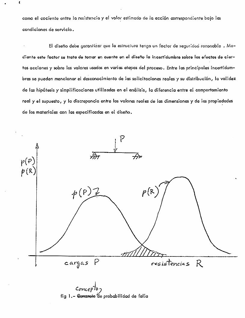
e
como el cociente entre la resistencia y el velo~· estimado de la acción correspond¡ente bajo las
condiciones de servicio.
El diseño debe garantizar que la estruc~ura tenga un fad'or de segur~dad razonable • Me-
cliante este factor &e trata de tomar en cuenta en el diseño la incertidumbre &obre los efectos de cier-
tas acciones y sobre los valores usados en varias etapas del proceso. Entre las principales incertidum-
bres se pueden mencionar el desconocimiento de las solicitaciones reales y su distribución, la validez
de las hipótesis y simplificaciones utilizadas en el análisis, la diferencia entre el comportamiento
real y el supuesto, y la discrepancia entre los valores reales de las dimensiones y de las propiedades
de los materiales con las especificadas en el diseño.
CWtceff~) fig 1.-€~ 'éle probabilidad de falla
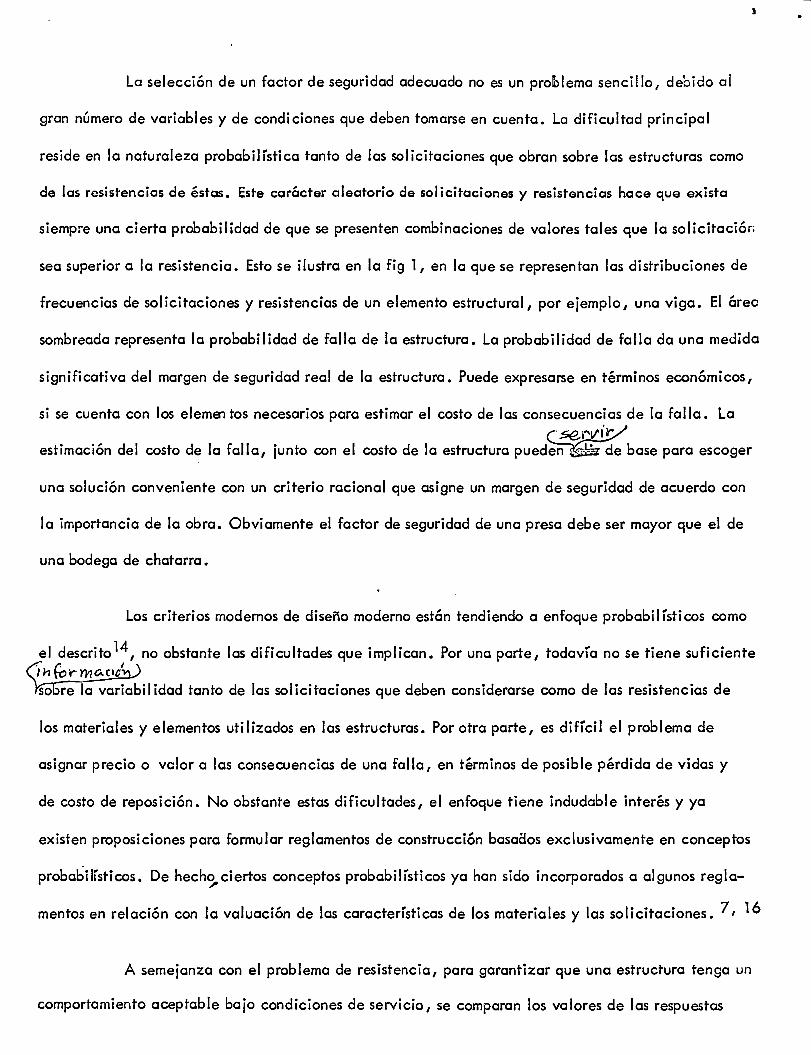
La selección de un factor de seguridad adecuado no es un prolblema sencillo, debido al
gran número de variables y de condi cienes que deben tomarse en cuenta. La dificultad principal
reside en la naturaleza probabilística tanto de las solicitaciones que obran sobre las estructuras como
de las resistencias de éstas. Este carácter aleatorio de solicitaciones y resistencias hace que exista
siempre una cierta probabilidad de que se presenten combinaciones de valores tales que la solicitaciór.
sea superior a la resistencia. Esto se ilustra en la fig 1, en la que se representan las distribuciones de
frecuencias de solicitaciones y resistencias de un elemento estructural, por ejemplo, una viga. El árec
sombreada representa la probabilidad de falla de la estructura. La probabilidad de falla da una medida
significativa del margen de seguridad real de la estructura. Puede expresarse en términos económicos,
si se cuenta con los elemEntos necesarios para estimar el costo de las consecuencias de la falla. La
c>e.ndt/ estimación del costo de la falla, junto con el costo de la estructura pued~de base para escoger
una solución conveniente con un criterio racional que asigne un margen de seguridad de acuerdo con
la importancia de la obra. Obviamente el factor de seguridad de una presa debe ser mayor que el de
una bodega de chatarra.
Los criterios modernos de diseño moderno están tendiendo a enfoque probabilísticos como
el descrito 14, no obstante las dificultades que implican. Por una parte, todavía no se tiene suficiente 6n for-rnAcie-1,) Ysobre la variabilidad tanto de las solicitaciones que deben considerarse como de las resistencias de
los materiales y elementos utilizados en las estructuras. Por otra parte, es difícil el problema de
asignar precio o valor a las consecuencias de una falla, en términos de posible pérdida de vidas y
de costo de reposición. No obstante estas dificultades, el enfoque tiene indudable interés y ya
existen proposiciones para formular reglamentos de construcción basaaos exclusivamente en conceptos
probabilísticos. De hech<3- ciertos conceptos probabilísticos ya han sido incorporados a algunos regla
mentos en relación con la valuación de las características de los materiales y las solicitaciones. 7' 16
A semejanza con el problema de resistencia, para garantizar que una estructura tenga un
comportamiento aceptable bajo condiciones de servicio, se comparan los valores de las respuestas
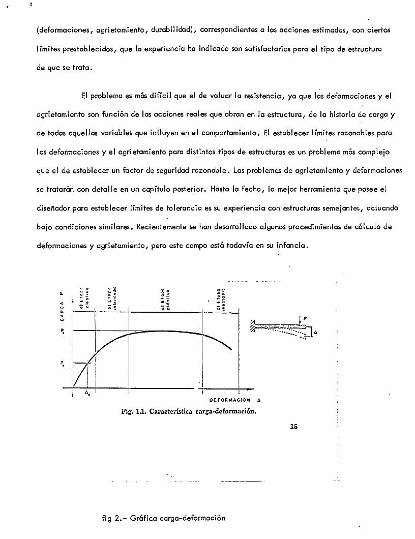
-.
{deformaciones, agrietamiento, durabilidad), correspondientes a las acciones estimadas, con ciertos
límites prestablecidos, que la experiencia ha indicado son satisfactorios para el tipo de estructura
de que se trata.
El problema es más difícil que el de valuar la resistencia, ya que las deformaciones y el
agrietamiento son función de las acciones reales que obran en la estructura, de la historia de carga y
de todas aquellas variables que influyen en el comportamiento. El establecer límites razonables para
las deformaciones y el agrietamiento para distintos tipos de estructuras es un problema más complejo
que el de establecer un factor de seguridad razonable. Los problemas de agrietamiento y deformaciones
se tratarán con detalle en un capítulo posterior. Hasta la fecha, la mejor herramiento que posee el
diseñador para establecer límites de tolerancia es su experiencia con estructuras semejantes, actuando
bajo condiciones similares. Recientemente se han desarrollado algunos procedimientos de cálculo de
deformaciones y agrietamiento, pero este campo está todavía en su infancia.
< o a: < u
p •
" o ~u o= ·' - .,
o o ~"' ~ "' E ... ~
o ~
o o ~ :,; ...,
o
"' o
... ~· "'·o ¡ ~~ V r----t--t-~-j
~~ -;; Q.
1 1
1 1
1 1
h· Vl
:.. OEFORMACION .6
Fig. 1.1. Característica carga-deformación.
fig 2.- Gráfica carga-deformación
15
. .,.. ILUSTRACION
Para fijar las ideas anteriores, éstas se aplicarán a un caso específico., (onsidérese el ' ..;.._
voladizo mostrado el} la fig 2. ~:~~a la acción de una carga vertical P que varía desde un valor
nulo hasta aquel que produce el colapso. La característica acción-respuesta más inmediata es la
curva carga-deflexión presentada también en la figura.
En términos de esta característica es posible definir cuatro etapas en el comportamiento
del voladizo:
a) Una etapa inicial elástica, donde las cargas son proporcionales a las deformaciones. Nor-
malmente se pretende que bajo las condiciones permanentes de servicio (excluyendo las cargas de
corta duración como viento o sismo), la estructura se encuentra en esta etapa. La carga de servicio
se ha marcado en la figura como Ps y la deformación correspondiente como.L\ s·
b) Una etapa intermedia donde la relación carga-deformación ya no es lineal.
e)· Una etapa plástica, donde se producen deformaciones relativamente grandes para incrementos
pequeños o nulos de las cargas. La resistencia (PR) se encuentra en esta etapa. Debido a la forma de
la curva es difícil establecer cual es la deformación correspondiente a la resistencia.
d)Una etapa inestable, caracterizada por una rama descendente hasta el colapso, donde a
mayores deformaciones la carga disminuye.
De la ilustración se puede definir el factor de seguridad como el cociente PR/Ps. La estructura
tendrá una resistencia adecuada si este factor es mayor que un valor predeterminado considerado como
aceptable.
Para investigar si el comportamiento bajo condiciones de servicio es satisfactorio se deberá
comparar el valor de la deformación correspondiente a Ps con ciertos valores prestablecidos que se
o -¡_
estimen tolerables, de acuerdo con experiencias anteriores.
Es interesante hacer notar que en la etapa plástica, a una variación muy pequeña de la carga
corresponde una variación importante en la deformación de la estructura. Por lo tanto, si las acciones
en esta etapa se detenninan a partir de las deformaciones, errores importantes en la estimación de éstas
producirán sólo variaciones insignificantes en el valor de la acción. Por el contrario, es difícil predecir
en esta etapa el valor de la deformación que corresponderá a una carga determinada. v
El· ejemplo anterior muestra claramente que es necesario conocer las relaciones acción-respuesta
correspondientes a una variación de P desde un valor nulo hasta el que produce el colapso. Esta in-
fonnación permite conocer el grado de seguridad de la estructura y estimar el intervalo de carga bajo
el cual el voladizo se comportará satisfactoriamente.
4. LAS SOLICITACIONES
Las principales solicitaciones o acciones exteriores a que puede estar sujeta una estruc
wlva..s/ tura son: cargas estáticas debidas a peso propio, a cargas~ y a cargas pennanentes, así como
Cr_<¿p~llclo./ cargas dinámicas impuestas por un sismo, por la presión de un viento, o por la aplicació~as
1\
vivas. También se consideran como solicitaciones las deformaciones de la estructura inducidas por
asentamiento, por contracción y cambios de temperatura.
Al estimar las solicitaciones es necesario prever las condiciones más desfavorables en
que la estructura podrá encontrarse, así como el tiempo en que estará sujeta a estas condiciones
desfavorables. Para hacer un análisis riguroso sería necesario conocer las variaciones probables en
la intensidad y distribución de las cargas a lo~largo de la vida útil d'e la estructura, cosa difícil
de lograr.
En el diseño estructural se ha hecho hincapié en el desarrollo de métodos de análisis de
estructuras, pero se han llevado a cabo estudios muy limitados sobre los valores probables de los
cargas que actúan. Es aquí donde se pueden cometer los mayores errores, y donde nuestro conocí-
cimiento es más exiguo.
La estimación de las cargas debidas al peso propio puede hacerse con relativa precisión: los errores
no serán mayores del 20 por ciento si se han evaluado con cuidado los volúmenes de los materiales
y los pesos volumétricos.
En lo que respecta a carga viva, los errores en la estimación pueden ser del 100 por
, ciento, o aún mayores. La carga viva está especificada comunmente en los reglamentos de construc-
ción como una carga uniformemente repartida equivalente, con distintas intensidades de acuerdo con
el uso considerado, o bien, como una carga móvil idealizada sobre puentes o viaductos. Estos
valores equivalentes especificados tienen como base estudios muy limitados. Los efectos de las
cargas equivalentes en la estructura pueden ser muy diferentes a los efectos de las cargas reales.
La estimación de cargas laterales debidas a viento o sismo está sujeta aún a mayor
incertidumbre. Fácilmente se cometen errores del 300 por ciento o más en la estimación de los
efectos de estas solicitaciones.
En el estado actual de nuestro conocimiento puede esperarse solamente que, con base _/
en la experiencia, se especifique un tipo de carga tal que unido a procedimientos adecuados de
diseño y construcción proporcione una estructura que se comporte satisfactoriamente.
5. EL ANALISIS DE ESTRUCTURAS DE CONCRETO
Para poder analizar una estructura es necesario idealizarla. Por ejemplo, una ideali-
zación frecuente en el análisis de edificios es considerar la estructura como formada por series de
marcos planos en dos direcciones. De este modo se reduce el problema real tridimensional a uno de
dos dimensiones. Se considera además que las propiedades mecánicas de los elementos en cada marco
están concentradas a lo largo de sus ejes. Sobre esta estructura idealizada se aplican las solicita-
cienes.
"' -
Las solicitaciones o acciones exteriores inducen acciones interiores (r.1omentos, fuerz::::;)
de intensidad variable. El propósito fundamental del análisis es valuar las acciones interiores en las
distintas partes de la estructura. Para ello es necesario, salvo en estructura~ o elementos isostáticos,
conocer o suponer la relación entre fuerza y defonnación o, en términos más generales, entre acción
y respuesta.
La hipótesis más simple que puede hacerse para relacionar carga y defonnación, es la
de suponer una dependencia lineal. El análisis elástico de estructuras parte de esta hipótesis.
Otra hipótesis relativamente simple que se hace para el análisis de estructuras es la de
suponer que las acciones interiores, al llegar a cierto valor crítico de la acción, son independientes
de las deformaciones. En esta hipótesis se basa el análisis límite. En él,se tratan de obtener los
valores de las acciones para las cuales la estructura se vuelve un mecanismo inestable(
Existen otros tipos de análisis más refinados, con hipótesis menos simples que las anterio
res, que se aproximan más a la realidad. Debido a su mayor refinamiento son más laboriosos, aunque
con el empleo de computadoras electrónicas se usarán cada vez más.
6. EL DIMENSIONAMIENTO DE ELEMENTOS DE CONCRETO REFORZADO
Se entiende por dimensionamiento la detenninación de las propiedades geométricas de
los elementos estructurales y de la cantidad y posición del acero de refuerzo.
El procedimiento de dimensionamiento"tadicional, basado en esfuerzos de trabai<?~ con
si:;lÍa en determinar los esfuerzos correspondientes a acciones interior~s obtenidas de un análisis elás
tico de lo estructura bajo sus supuestas solicitaciones de servicio. Estos esfuerzos se comparaban con
esfuerzos permisibles, especificados como una fracción de las resistencias del concreto y del acero.
Se suponía que se lograba así, simultáneamente, un comportamiento satisfactorio en condiciones de
servicio y un margen razonable de seguridad.
El factor de seguridad de los elementos de una estructura dimensionados ¡::¡or e; método
de esfuerzos de trabajo no es uniforme, ya que no puede medirse en todos los casos el factor de segu-.
ridad por la relación entre las resistencias de los materiales y los esfuerzos permisibles. En otras
palabras, le relación entre le resistencia del material y los esfuerzos de trebejo no es siempre igual
e le relación entre le resistencia del elemento y su solicitación de servicio.
El procedimiento más comúnmente utilizado en le actualidad es el e veces denominado
método plástico, o de resistencia o de resistencia última. Los elementos o secciones se dimensionen
pare qu7 tengan une resistencia determinada.
El procedimiento consiste en definir les acciones interiores correspondientes e les
condiciones de servicio, mediante un análisis elástico y multiplicarles por un factor de carga, que
puede ser constante o variable pare los distintos elementos, pera así obtener les resistencias de
dimensionamiento. El factor de carga puede introducirse también incrementando les acciones exte-
rieres y realizando después un análisis elástico de le estructure. El dimensionamiento se realiza
entonces con les hipótesis de comportamiento inetástico.
El procedimiento de dimensionamiento plástico puede también aplicarse e los resultados
de un análisis límite, del cual se obtienen directamente les acciones interiores correspondientes e
le carga de le falle que convierte le estructure en un mecanismo. El dimensionamiento e partir de
un análisis límite no es todavía de aplicación práctica debido e las incertidumbres que se tienen sobre
mecanismos de colapso; l.a inestabilidad general de le estructure y le capacidad de rotación de los
elementos de le misma.
El cnál isis 1 imite no debe confundirse con el criterio general de dimensionamiento, deno
minado de estados límites, que es el presentado en las recomendaciones del Comité Europeo de
Concret~·-t en los reglamentos soviético? e ingleses l9. El enfoque de estados límites no es sino un
formato en el que se consideren todos los aspectos del diseño en une forme ordenada y racional y que
·'
permite la fácil incorporoción de criterios probabilísticos. De hecho se treta de lograr que las carac
e~i/1\. terísticas acción-respuesta de un elemento estructural o der una estructuraf.Jentro de límites que se
consideran aceptables. Según este método1 una estructura o un elemento estructural deja de ser útil
cuando alcanza un estado, llamado estado límit~en el que deja de realizar la función para la cual
fue diseñada. Se distinguen dos grupos de estados límites: a) Los estados últimos, o sea, los corres-
pondientes a la capacidad de carga, y b) los estados límites de servicio, que son ios correspondien-
tes a las condiciones normales de servicio. Entre los primeros figuran la falla por ruptura de secciones
críticas, inestabilidad, volteo, fatiga, etc. Entre los segundos se cuentan la deflexión y el agrieta-
miento. El diseño consiste en que la probabilidad de alcanzar dichos se mantenga dentro de un
margen razonalbe.
El Comité Europeo de Concreto da recomendaciones específicas al respecto.
REFERENCIAS
l. C. W. Churchman, 11 The Systems Approach 11, Dell Publishing Co., Nueva York (1969)
2. A. D. Hall, 11 lngeniería de Sistemas11 1 C. E.C.S.A. 1 México (1969)
3. H. Chestnut, 11 System Engineering Methods11, Wiley, Nueva York (1967)
4. R. de Neufville y H. Stafford, 11 Systems Analysis for Engineers and Managers11, McGraw-Hill,
Nueva York (1971)
5. Fazlur R. Khan, 11 Üptimization of Building Structures11, Proceedings 1966 lllinois Structural
Engineering Conference, Structural Engineering in Modern Building Design. University of l!linois
Bul:e¡·jn (1969)
t 6. N. Khachaturian et al., 11 lntroduction to Structufal Op~imizatior:t 11 Waterloo University,
Watedoo, Ontario, Canada.
7. E. Sigalov y S. Strongin, 11 Reinforced Concrete11, Foreign Language Publ ishing House, Moscú (1962)
8. 11 Reglamento de construcciones para el Distrito FederaP•, Diario Oficial, México, D. F., (1966)
9. F. Robles, 11 Concreto Reforzado 11, Sección H del 11 Manual de diseño de obra civiles11
, C.F. E.,
México, D. F. (1970)
10. 11 ACI Standard 318-71, Building Code Requirements for Reinforced Concrete .. , ACI, Detroit,
Mich. (1971)
11. 11 Commentary on Building Cede Requirements for Reinforced Concrete (ACl 318-71)11, ACI,
Detroit, Mi ch. (1971)
12. E. V. Krick, 11 lntroducción a la Ingeniería y al proyecto en la ingeniería .. , Limusa-Wiley,
lv\éxico ("¡968)
13. L. Spunt, 11 0ptimum Structural Design 11, Prentice Hall, Englewood Cliffs, N. Y. (1971)
p 14. E. B. Haugen,11 Probcbilistic A~roaches to Design11
, Wiley, Londres (1968)
15. Moreno Bonett, Jauffred, Acosta, 11 Métodos de Optimización, programación lineal, gráficas, .. ~\
Representaciones y servicios de ingeniería, México.
16. 11 lnternational recommendations for the design and construction of concrete structures11, Comité
Eurcpe@n du Beton-Federation lnternationale de la précontrainte 11, Cement and Concrete Assn. ,
Londres ( 1970).
17. E. M. Asimo\1, 11 lntroduction to Design11 1 Prentice~Hall, Englewood Cliffs, New Jersey (1962)
18. J. R. Wright, 11 Performance CriteriQ..in Building .. , Scientitic American, (March 1971)
19. A. L. Baker, 11 Limit Design of Concrete-Structures11, Cement and Concrete Assn., Londres (1971)
Proc.eed111?"s of. a S· •11.po7/V1 vr1
20. L. E. Robertson, 11 0n Tall Buildings11 1 on Tall Buildings held at the University of Southampton,
April 1 1966, Pergcmon Press, Oxford (1961)
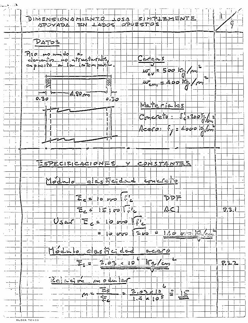

' c4-~UJ~F =l=~f1f 4=-~¡.-=
~; i--+---l-j--fli--J.-------j-+----J--+--+------+-cft-~4~~ 5-~-, -+----+---+-~--~-~--~---·--~----~ --~
1, ~ ~-
·-------"--J
~-
¡J -f---'JI-~
~-t ~--
a¡-();-=· r-13
1---
-· --+--1---1--:_i-
~ 1
1 L
~
~ -~
'" ~
-=
"
d:, =
~ ~~
¡---¡-· -! -~ 1
, 1
6i-6+--¡ ---r-~-n
1 ·~
-~-:+-~-u~-ul~--t--~1-l--~--¡--f--1--!:rt-~=~o~-.-~~.~~
__ L _ _ _ 1_ _
•
:--·--~-+--+~ -
~ ~f---m~~
-t-LI-f--
!---~--¡ ¡---r+-~
-1----1----~ 1
-~ -~ 1-l·-+----J--j!--+-----+---l
¡----¡ --r--c--GJ
j=í--=g= -~-~-
~~ f-
¡4\1 -+
-+-+
--i -
-·--~--
_J nl-
1--
j) t--+---+--------i
1 ·¡
1 \:;¡
~~
""1
t~--' T -. ~
~rr1= 1:_~ _
. ~-~1 ~ __ f
-__ Q'· -=~~---J
¡---\-L--[-~
J ~ -~
~---
al •--L¿, ____ }ll_j
¡--;-<~ Zl
------J
. ~~-~
1 -r.¡-----~
_¡ 1
1."\,
1 .
1 'll¡
1 ~
1 '.
-:--~ ;~-----l-e---n4 -~-
'-'L ¡--
·J" ~---al-
~
J
~-T-~_l_ -H-~ ~
-L~J±~L¡-Jr--~-
¡ '
o-E-k--=r~ ~--.-n·-~
2-rr~ -f--1-~[-r-lri~
Jl-. r;_L_j~ .
-1-e----~L-
_1
~-=I __ L~ L--~~::t-rt\):++.3
1 ~ -+~ l_
j 1_~-\1-
~=-1-~!:---+
~~-+-+-~~-~LP-~-' r-4--i ~----~_::~
_l
u, U.
~r ._\l. o ___ t_
~~-ar J-i-~-----~ d--L-~ó:-~----~-~
1 • lT
1
1 ru
1 1
~ ~·
' 1
:J)J_ 1---~-1---
1 -_,--1--r • ------------
: 1
' 1
1 ~
, ~1
--
1-r
------\1-
¡-¡---
--t --aui-·--::-,-r4- 1 -f-. ~
"--~a-; '
·-~--z-~-;
, . -~-·~-H~~ ~~---~~-tJ,·-tl
~-__ { _ -,..}+ -~--
~~-r-r-·17_~-_
t---_
_j-:
1 1
,,,
• V
l ~
. !
'-"'
~
1 •
1 •
1 m
T 1~
l"i i
: --~-~-~----.,\
1 l --
w· L ---
~
r--~
r -;,t
~-----
--9---,.n~ ro'---~-~ -¡ -J
----[o -¡ ----~-r-----1-~--¡--
-----
--
1 -
1 J 1
,\..J
1 ,Q
1
, 1
;!.:; , 1
e' . '
: -~~ -
---
---
~---:\)j·-A -
--,--¡----""+-
¡
l:~==---] -W-il --;itll~d-~ +
.,:_=I.J=p.~ ~[--~=-~~~-~ f-F~=t··. ~~~k[ +l~ ~+f-·¡-t-¡~1~ :-----: \1]~--'1 ---,v~-j-t_, ~-~"' J"-~----~
_ ---~--='--:1 1 ~~ ur~ ~ !=~ --¡-;:-?j--~-~ --1-r~
¡1-j~ -¡ ~---
: __ :_l_
_ 1 ~ _¡
L~ JL
:_ 1
-\\:A
.! 1
1 -.-
--
-0! -¡---~-r-· ---¡--r---
:---~---¡
: '
t w
~~-_h ,e-~ j~----+~ -¡---~--~~·~-
"•r----\¡'}f-~--c-1---
L __ yj· ---
------'~ ----~----¡-
-: -
----------l-
_l -·---~
--~¡----~----
__ 1 ---
J _____ ¡___ -
1 1
1 1
1 1
1 :
1
i , ~
1 ¡V
1 1 J
tJ. ~-
1 ,
--1 t
1 ~-------------«~---------1----r--¡-~--~-----~----~-
--~ L
--------
__
_, l
_¡__ -~ L
u.;
~
~
1-1
1 L
.
o <.>
"-1--~ ~
J----!-1~ L_ ----------~ ----. -----
-~--~-----[-;~-------~------------1-------1----1----j---1--
1-j---___ l __ :7"_--, _ _~ ___ , __ ¡_--1----1-l-
1-i -i--!--
j !-!~~
------------r------------------1---------
1 ------
-----
--,-
----~r---.----
-1--1--"
---
, __ 1 --------
1 -1-----1
-. -1
-1 -
1 -1 -
:--
1 •
• 1
_:
_ : _
1
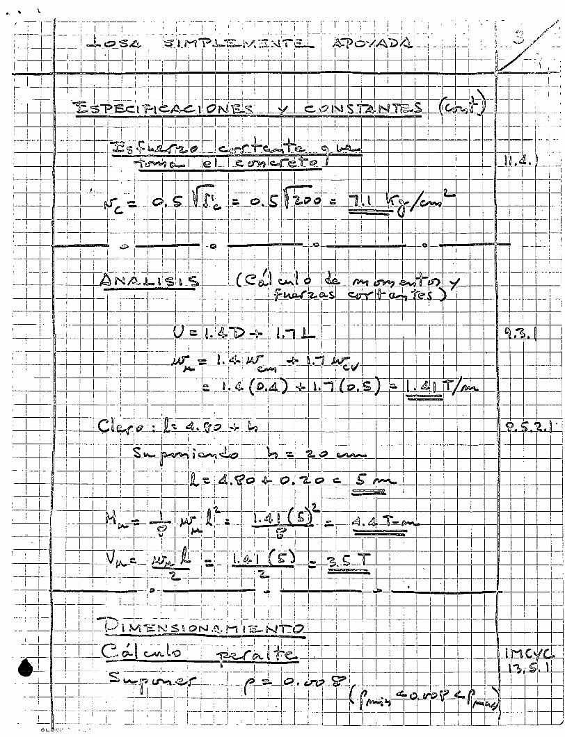
·\~ '
-\ __ :
-:--
, --:--
_l_ j ------
_L
_r-----
----r-----
-_cJ:_
~ ~
--¡
--,-
~-
1-i --¡--'-
¡-~¡----r~--¡ ,--.-
.. ---
.. 1-f~--
-----.. ---
~-
---~pj-_l ____ __
'--<-:~-
---!----~~-L -~-~-~1 1
--
1 .1--1----+--+
-+-+
-+-+
-+-t-t--+
----+---¡----¡---t_ 1---:~u~
--
f/)~---j-C-
i ~ .. J 1
~1 J
-~=~-¡------, -:\
' .. -n
';
a¡ .
. '
, 1 7fl ~
·"~~~-i1J l i ,
, ~
~ ·
~-r 1
¡
,----~---~~--r-:
3 r, d~------~~11 -
-r----r------~~--~+-, -~ 1
; ~+ ll : , 1 ~~L_
~ ~-~
-f--~1' -r-
_ _¡ -~:=c:=d-
l r·5t::::¡_ --
m
1 ~~
~i _
j +
1 .
1 1 ~~-[~
,---:-A 1
: ~L
+--t--r--t-f:'-
[JJ I¡TII-'i
1 1 =--=r--r1
=_: :--f-~+
~ .
-+d ~~
--¡-9-r---F 1 ~-~rll¡---~--~ ~:-t--~--r--l=r_¡_j_ l1_~
!----~-o---~-~ 1
:-r----8 --r-
{r-1
r---
lO.r-r-'
-+--i ¡--·•..1)
¡-!--~--~ ~~
--~~r-[J
I __ C:L_ 1
~:::: --t-J.
¡ 1
: 11: ±tg+--~ J t ol-"'1-r-t.¡i ~1B$t-W<4' -
1 ~~_G-1~'-f=p:~-i
~++~-Y--1 ! ,¡~
1 : ~~ ~~~ ~~-~-¡-J- 11+--L--si-1
1 :---l¡ rl-t:=--t!t= -J-=~HI [~ -1__,_:-,J it:: ·~l Jr8
¡ ~ 1 ~ =:t J
¡--!-.
--,---------r-)i.---1-~( '
1 ~
IL-
-+
--1
J:-~~-:-r-t~: 1
1 1
¡--J 1
i :~ ~
~
. 1
1 1
! z ~=-
1 .1
'¡ 1
: )~ i
1 __]_¡_~-;U
),--+-
_[_
__ ~·--¡----~~ _, ___ ¡_ s-~"!-.------
Ji-,-~-+--~--·---~---·-:----1-"' -
~ -~d----
r--: ; ' ~;r-~----
, 1
; 1
: •
· t [_] ~·~_¡ _J ___ L
~ ~---"-_l_ __ J ~• .. ! _ _1 t..' __ L~i. ___ 1 1~-'--"' _
)±]_
": ___ : _ __!_: __ [ ___ 1-~ --
•1 ---
' __
_ _: _
__
~ Pr\ --~-~ -:--"1----1
:--! ~
-"---~-~---
--y
-~
-1 u
r
1 V
,
1 '
l 1
::;( ·--
dj
¡ 1 u
' 1
1 1
1 1
'!.. ¡
1· 1
. "-
1 1
1 -'-•
! --j~Vi --~\,l-
+--' __ ¡_· L_~/_--~-~ 1 _
1 ___ 1 _ _j __ '(\i---!---~--l-.{--¡'---\----·----L-,
: ~--,----r--L---~ ___ j_
_ --j __ _
1_
---~-
-+-¡---\---¡--
-~~--:J,~~-t-~-~ ---i---+-J ~ Il __ _r~--~~-: J~--~~--~-~~--: i-!-~!~~--~:---¡-:~-~-<-~i----~~-~~-/--j-.1-[----¡=;} ---:----;-~ :-~:-¡--~--¡-
, --; p,--~¡-¡--~\)' -¡-¡ 1 -; L(~±-f UT
tJ ·¡'-=-J~~-~j'=,q=.r:.c: ¿~_:-:; r ¡ .. :-t4
iLfi1
:J
~ ¡:_:-; i ....
1 + Lf
1
:_ [=-_1_ =----J -¡
~~¡ -¡ -~ ~--+-_II~ _C __
¡ __ «•-1---!t-~ ---W-~~--~-~~~--;~~-I-~--!-kw 1 --1-+~--~ --
--! -'J---1---:----_! __ ~~-
_ -~
__
1 u~ -J =!l_lafi_l
__ -~~ __ 1_ ~-D~----~-L~ __ LL"f-+B~~---_1-J--:--l--!--' ~
--~-1 Vl -~
, t'~ --;--¡---: ~-i
1 1 ~,,
U_~ _t _tll __ l
l __
_ j_jj_qp _____ t----L
__ 1 1 _
_ ~~-LL_I __
1--t.J<l\, 1---:-~ _
_ ,_
, _ _¡__! z
~ , r ___ J1 -1 ~--
,-----
----,--v. -
, Cl
H
1 -
1 1
1 1
1 '
l 1 ~
1 ~
1 1
1 1
~ ,
! J :r
j_!_ __ l__I __ , ___ I __ L _ _
L _
_ ~ _
__
__
__
__
__
__
__
__
__
¡_·J __ LJ,_I __
__
___ ¡ ____ ;_-.. __ ·---~---:
t!! 1
~·--¡-+--
¡---
:---~= -
~-L!~
1 1
1 1
1 1
1 1
l 1 ~
l '
1 1
1 1
i ¡ ~
~; 1
'
r-
1 '
1 1
' i
' ~
' 1
1 1
' "
1 1
1 1
1 1
ll 1
_) 1
..... '
'
¡-· tn~--_,_~_
-"-·J.J ,
-;
\J.-:
~~ ~-
: z --1-¡---1--,-
-¡-----~--r---
-~---¡----~----¡--~~---~
---·-:i-¡--~; -~ -~--
--· (\
~ vt
: :
~-~:~=:=~ tffiil~I=Jt = ~--t===J=L tt= __ ~P1f' __ :=~=t~E t~:-'~ J-!1Hi _1 !,_¡-:
1 :
¡u: r+= = ~++-=r=rr---H=Fi=+-1 -¡-~!-1=--·r=~.-+r ¡::::¡:=¡:.J -¡-1· =1--
+--+= il +¡·++ H -+-h t
~ F~-~l .. !=~±j~~--~~~--·ftt··---~-~:=t=:_:-. -=l-----.. ]~=~~·~. Tl==.=!=· t·! --1-!~++-l-l'
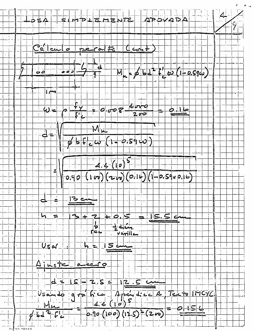
•• -p
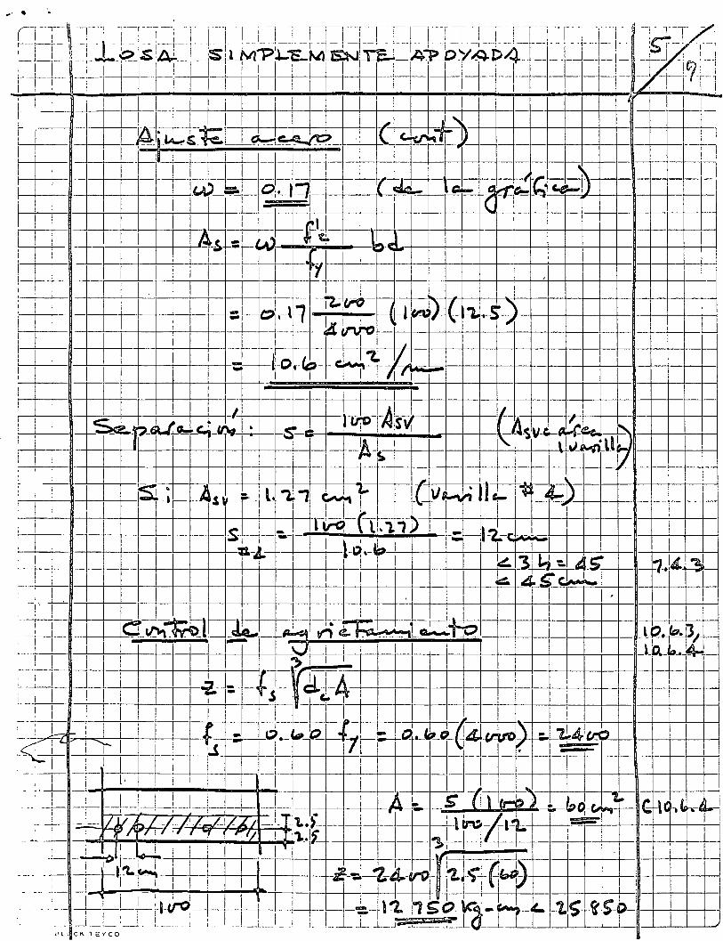
• • ¡ ...
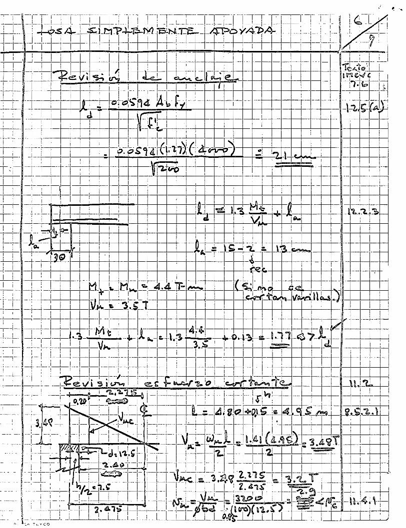
-· ...
--i
l _, '
1
1 ;
i ¡
. ' ¿
1 1
~--1
'---!
l '
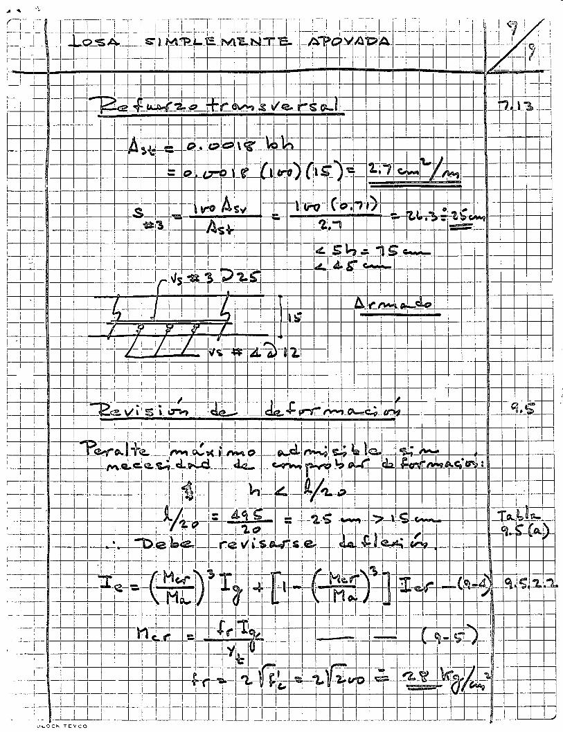
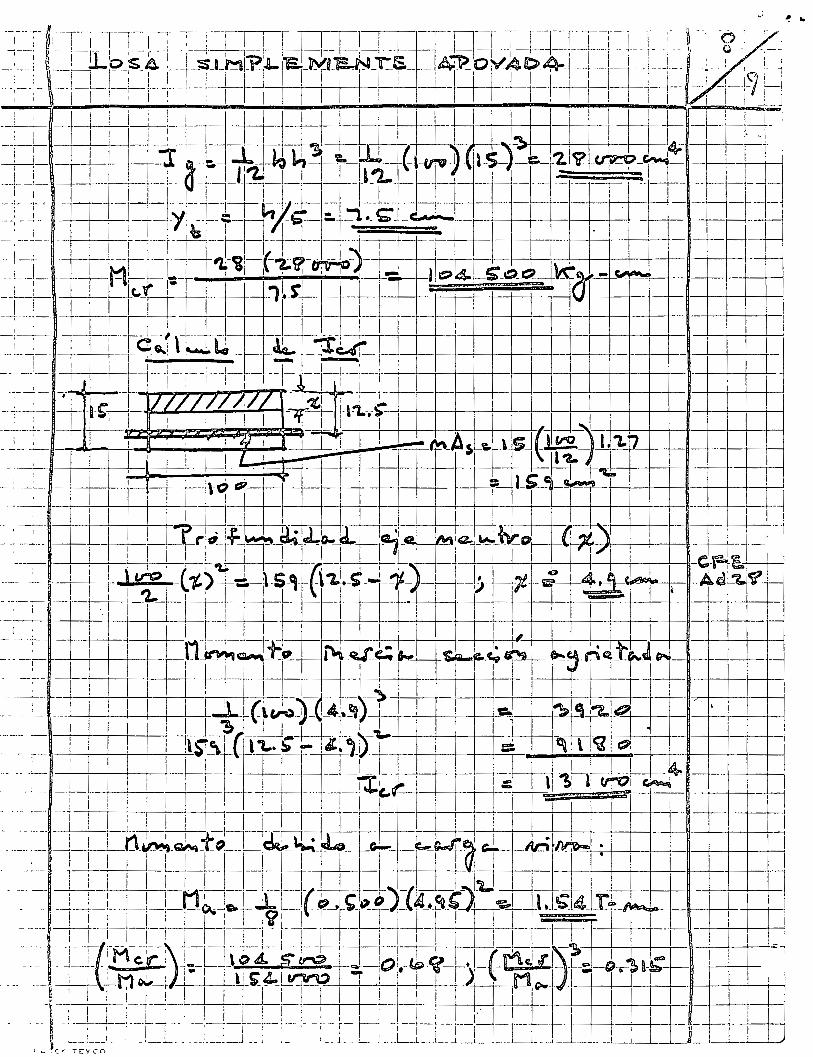
r----t--+--+--t--
.. ir
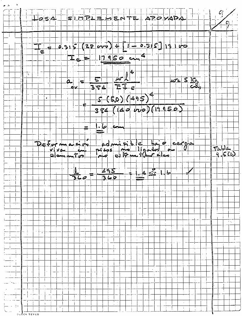
f¡
1
:J 1
•"
' 1
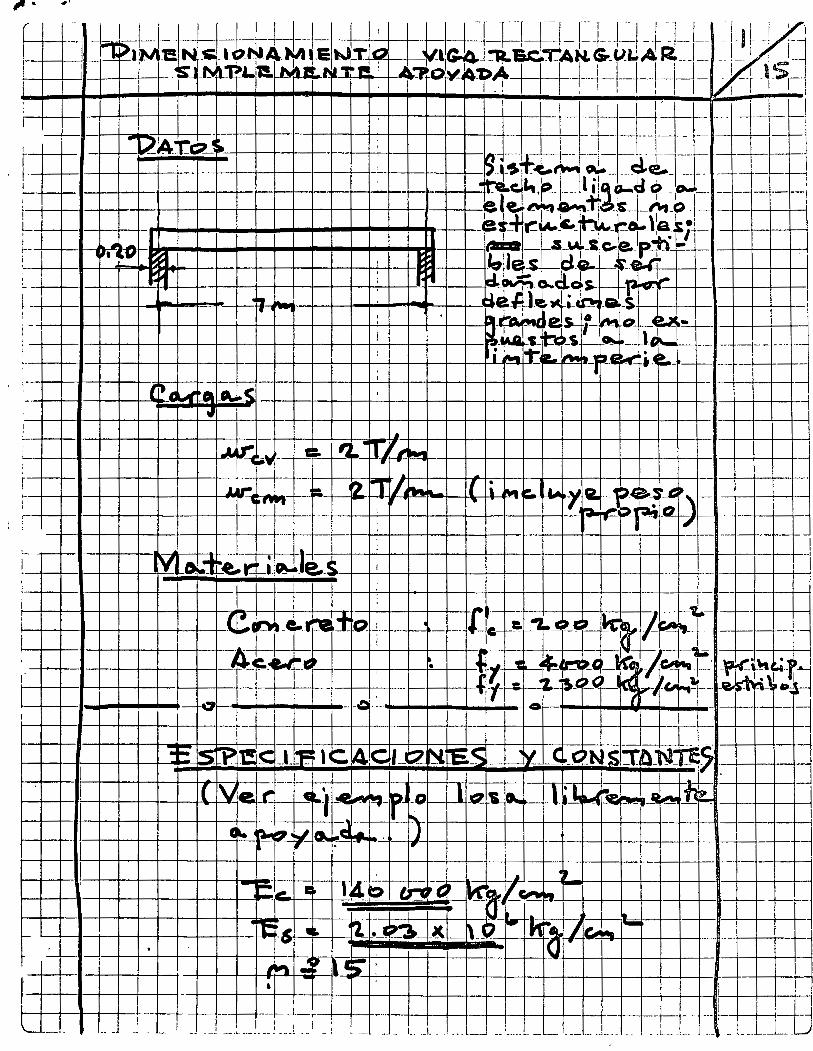
11
fll V
¡¡, 01
r~
1 1
¡-
1
~
1 -,_ J 11>
1(\
·, -¡~
' ~.~
. 1
! 1
¡ 1
1 -
__
: _
_
1
¡--
¡ -+
--+
---1
1--+
-t--
+-+
-f-+
-+-1
-+--
+--
-11-
-+-+
--+
-' ~
l 1
1 -
_ ____
; __
! ~
~
1
~ --+
--+---
-+--+
-----+
-+' -+
--1-
-+-1
--1-
--+
--+
--+
-+--
--+
--r-
._.
i ¡
! 1
-----
_1
-
1 '..::
i !
1 VD
l_
_i_.
--'--
-L--
'----
1---
--'--
'--i' -
1--.L
I _ _¡_
__
_ ,
__
c_
_L
__
L_
__
,L_
__
_ii
--L
'r'
-""'"'
Qt""~=
_:_-=.
_~~-_L+
-_!·-+-
_ +_LI
=~~=~~~~+Ll_j-+-, -+-
_ +1 -
jlf--+
l_L-+
-, ~=~=
~~-=
_,~-
-=._
~+~~
-_ _lr-
t_~--+
-_¡ .r
__ j_j_j_~
• 1

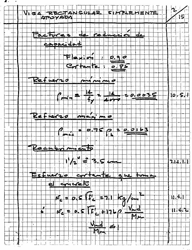
~~~r--. ~H-----~--~ J 1--• •·----,~,j:j-~~~~~l ~ : ¡ ; ~~~t:_:¿
1 ~ ¡ ~-
1---+--~-t---¡1 ~¡;p f'""~ ~ :l-+-1-+-' --+-l-+-1-+-+-+--+-'+-+--+--+-t-t--1 ~~~~~-+~+-hAJ~-J
1t-i-T~-~~-t--r~~~4-~-+~~~-+-r~~-+~
~-+---1----R--+---+--+--+--+---¡¡¡~:.0..:.:..~--r--,J--¡ 41¡
~~~?-~~l_-__ 1 -A-+--_-+_,~:~+f--'----~~-~-~-.+-+-1-+--+-+-+-+-+-+'-+-+-+-+---+-1-+-t--l j f--1--4--+--+-+-+-· .. lol.~-_ ••• -~.,:¡l-hl ., -= __ ~_,·t_:ll-•-•·c r¡¡ _!'llrv '
>-----r-1 ·~:u!__,,_--+-+----!--+-+-.. -~-....,-¡ """ ~--n--r...,:__t--t--t--l----r:-',_--+-~r-+--+-4--t-1f----i'l--+--+---l 4~ };.J=--11--+-+-t--+-1---1--+-t~-r--+-~~--ll--¡ --1--+--l
~---+---+---~----+---·ru "';;i~-a:--.... ....
f--+--+--+-+-n--+--+--+--t--+-+--+-+-+---h,.-+--+--+--1--+--t---¡t-¡---¡----t-----+~--t----l-1r._rc+-i'--+-+-tr-+-+---+--l-lr-+----l -~--&ii':6 ~---Mrl'l-1~ ?..JL~~~ +--¡-o -z;~ t!_l:=i e
t ~~-~;i·l ~k1y-1=, +-+--+--+---t---t-+--1-t---+--1-+--+--fl
1 1 ~~l_-_~-T~~-T~~-r-~~.~~~~~ ~~ ~ '•+-+-~~+-t-+~+-·~~ 1--+-+--+-t--+-+--+-+----l--+-+-+-f------1"·~1---'~ -o-r-11---1--
~-+---lf--+--1 ·Í --1-+---1--11-+-1-+--t--t-+-t--+--l-t-+-i
~-t--+---t-ll-1 -+---+-+--+-+--+-+-+--+-+--+-. +-1--t--+--+---c~¡~ ~~~'1-r-j ~~¡,-P"' ""' !.-. ~~+---~--+~+-~-+~+-~-+~+-~~~+~-1--+--1-~-+~~~-+~+-1~-+-1
t!=tl=tl=t~l=t§~~~~:tJ~!l17[tl:tJ:·tJ:t~yr~~~·+~~,~:~·~-:~+--~-~~-~-~+--+~~~r-~~-~-~+_~J t 411 t e .. ~ -:'" cv ; ,,. • ~ • 1 e--~
~~~-n~-+~4-~-+~+-~-+~+-~~~~~-+-4-~-+~~~-+~~-1~-+-J ~~~-.l-t~J-~-t~j_~-t~~~~~~~~~~~~~~~~4-l~-+~~ ., ,~ .r"f""lll~!iV ~~~ .. iP)'t ¡ ,~~-+~-+-~+~~._~~-.,-+-+-ll-+-+-
l--+----+---l-11---ll--l--l---1--1--+-l--l--+--l--+-l-+-~--+--+-+--1--+-+-4-+-+-+~-t--~-+~+-+-l-+-t---1 1
t ¡ 1-.+-.-4- ~.~-o+-·l r¡--1 --t--r:_:~:::::_:;:_::;:I.-~HI-~~· .. 11!--"i'l~"i-.H -f>+--+---~+---.. -+~;;---4-,~.--1~++ ¡-+---+-+-r-+--+--+--1--i-+-:¡ f .., .. ;;J ,... ~ ~ .. -, 1 -f-l ,~ '1--+--t-~+-t---+-1--t-1-t--+-: ~---+---1--f-+-+--+-+--+--+--+--+--+--+-+-+-+-+-+-~-l--+¡-1---+-+--l--+-+--+--+--+--+-+--+--+--+-l\--+--+--i
1
1
--m+r-~<L-t"/~<='~ ___ ,_ iSJJQ s\j--;a.,..Clt~-!--.. • -m--N~tL·;·:::>s:a~;~¡~ »'-~1-r'\l-__ t __ ¡_ --:--¡----~----['--·--I· -~~-~:
1 u---__ j_J~-~ ---tr=r~rf=f 1 ~-'-1-l-+----1---1 _
_l_ 1 _____ L _ _ __ __l__ _ __ U_l__l__ _ _ J_l_j_ _ ~-·-l-.~
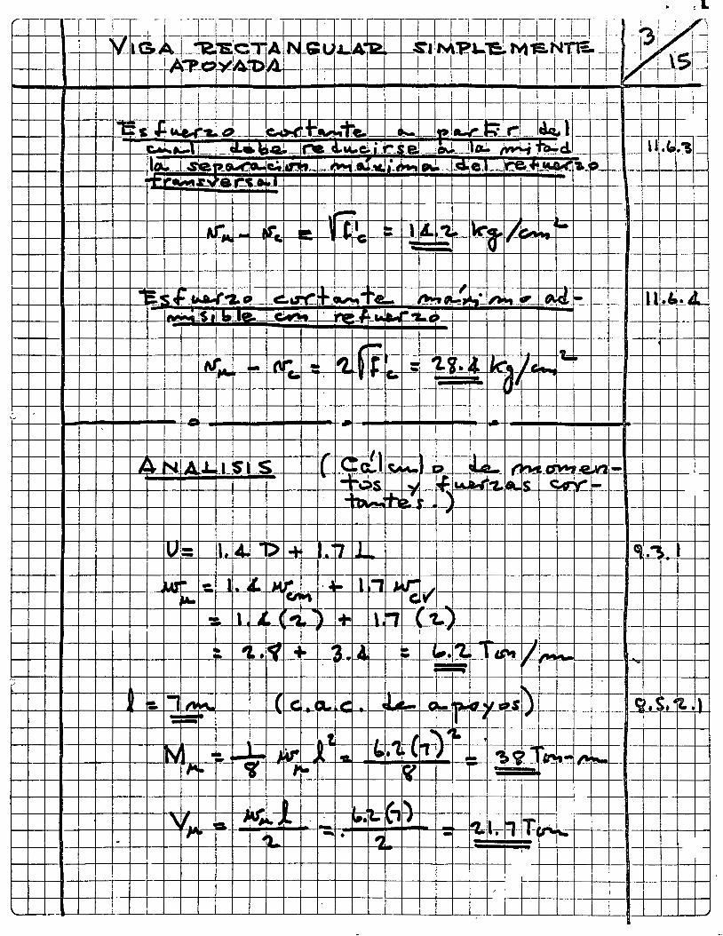
1
- -
~- ---t-+-t---+--+---t---+-+-+--+-- ~ 1 • -z
t--t---+--1~-+--t-11----+--flur_,_~---t-'o:. 1,. t. -'--" ~ · ~"" L, A-~ v't-+--+-+--t-+---+---t-+-+--1-,l--+--4---+-+-t
t-----+--+---•--lf---+---+--+---f---1----+--t---_; 1 ,. Li~L ,... 1 n f1:.,--+---+---t----+-+----+--+-----+-l-- -- --+--+-t-1
f.-+----+--~---+----+-+-+---4---+-f---'1'!':.~~~· !l ~- ·~ . ¿ ~ ~~ 1
"" t1~l·f'! ....... 'r"_-!--l---+-l-"..-l---l--t---t--i ~ r- ~ ~ l
:::-=.·=-::~-~-----'---~~~ --f!!+-~::r=1ll--~+:'"'--::::-=~~:c:·_c:::~-,..+-1..::.: ~:::L.:J: .... :-~t---_-~1r----+--~---r-+----+-c~s~+--+-+--+-_...__-+--_ -~~._s. 1t 1'
1--1-----+--11--+----t---t--+---+-ll!ll..~ JA-1 --l--1-• ~-1----l--+--+--a~.a· .. +-- n-11 t•~~t---t--t--l.+-"Zt--l""~ '~ -.., .. - - ---+-+--+---+---t
W-+--1~-+--+---W_jrii'V!t~_L/14.-J-•~;;,.~~c¡'~~l- "" '!!l. •• :~ 1 1 1 ·~ --~_g __ -~--A"- - -+--t-t--+-1
.1 ~ '1 12;-¡(, ' ' '1. !!!!!L w,.._~ ~ - ~· 1 - "!.¡l-. '1-¡T-, '1 ,..
•l_ -• ., - , ___ . - 1 -
! 1 -
¡ / '
! 1 í" _L
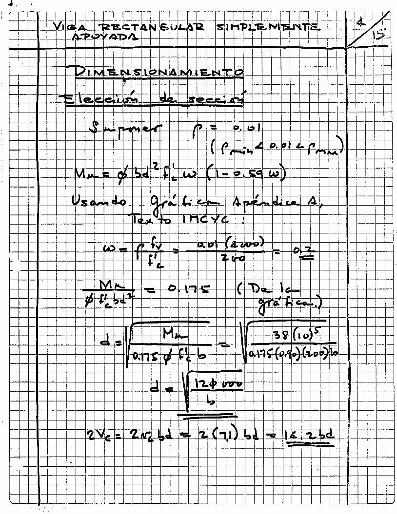
--l ___ ~ _J\----¡-1-r-t-t----t---t-H
-t---r-H-t---r-H
-+-t-H
-++
--H-i-+
--H-+
-+-+
--+-+
++
-+--+
--f 11--+-t-~-+-~W-t-~
. ·--
~-T~~~~~~-t-H-+-t-~-r+-~~~-+-+-H~+~~~~~~~~l_L!I~~~~~-L~
:--~ ;-·_-
-1y-l -¡---¡ -t!-: ¡! -tJ-t-t-t-t--H----t--t-t-t--t-H-t-+-t-t--t----1f-+-t-+-+-+-+-t--+-~--+-~+-l +1 -f---+---f--1-+i_¡_W~D
¡--, --, --~, ¡;:l---t l. -t---t¡-~!¡·---t--,,H---t--r--t-t---t!--t--t-+-t-+--+-+-+-H-+-+-+-+---if-+-+---+--+-l---1--l--, -+--+)-1Twi-+--1-_¡I_¡__J_+-+--+--~-----<
• 1
1 1
~ ¡
1 !
: !
' l

1 , • •
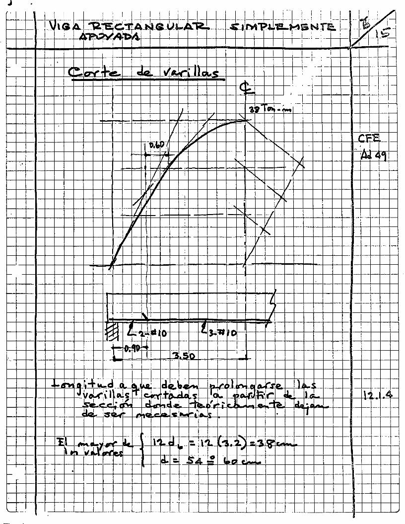
J 1 -f~--1-J-±1--1---1--:-~+t-td-U ' ~+-kJ-'-l_:_l~l-.l i '----1---~~ 1 ~
f---+-1--•____,~-.r-'-S A._ _"12,7E~· 1 G ~r~ A ~:' _Q_(l~A~---CI'M~¡l'f!-M & N TE:. !- ..,..._, 1 *'- 1 ~ ·--'!"· 1 1 l 1 ' ' 1
1-----+--+- _¡,¡ -- -~1>. --t-1-.¡ __ : _ _¡___;1 ._ -¡-.... 1 !
1 l l 1 ¡
! ' 1 1 .'-
I--+--+--I-...J....--.11--+--+--l-+-f-+-+--t-+-1'--l--+--t--t-t-t--t--t-t-+-t--+-+-t--i- - f·· : 1- ·--+---+----l
- +--l-l-+'-+-...l....-+-i--llt-+--+-+-llt-+-+-~l-t--t.-l"l;\-t-t---t--t--t-t-t--t--t--t--1- . -" -+-+-1--+--.\---f----
~-t-l-~r-f~cta~~~~~~~=~=~~~c;~~~~v~~~U~1~~;~~~c·~-r~tl-t~~~ --4~~~•-+-1--~~ 1 1 1
f--+--l--1--+--+--+--l-t--+-+-+-+--t-+-+-t-+-i-:+-t--t-t-t-+f .... t''-l---+-+--t-·' ' -l :---1-- -f--
l--+--+--l--+--~+---l'--1--f--t-·,--ll-+-t--t--t-t-t--t-T'--t--t-t--t~"' t::. 1 -- l = --- -~i---1-
~------+---+--+- ,_- -f--
~- ' 1 1.1 , 1 1---+-+--1-+--1--+--1-+-~F ~r , ..--a.~•-· 0 s-~-~-ot\1-4-+-+-+--+-+-+--+-+--+--t-11~-+--+-+-1 1-t----t-'--1-+--!--+--+-+--+-t-• .. -
._ 1'"'" -. -"l1 St-'0 -t--t-+--t--~-l--+-+--+-+-~---+--+--+-+-t-i--+--+-+-1--i ·- -+-+--1--1--+--+-+--+--+--t-- ¡- -
1--+--+--1-+-1--+--+--+-+-+--1--J.-~+-~-+-+--J-I--+-+-t---l--l--+-+-f-+-l--+-+--+-+-l--+-l--t-+-+'--l--l
1---+--+-1-+--.t--+--+--t-::¡.- ~- --- --t-+---+--+-- -h.-+-+--!-+-+--+-h.+-+--+-+-1-1--+-+-1---+--1 • ~ ~~ ----;_· ~- __ Q.._I3bl A.ll ele.."~-~-~~· ,J ~-Cf M~P- l IL
1--+-+--•-+-+-+--+-=-J v~¡\Jt~,_:[_~1_to,.,ll~t-l-'!t>L 1 1 .~~~6·1~ ~ 1 t.: 1--+-+--1-+-+-+--J---.!~e.~~ ~ ~-el .a! 1-11~ ~;L~ . L& -""'~ cla •. ~-. 1---+--+--1-+--l-+---+--.,.~"-~""-~ -+:s-u -~~11:1 ...... la. ~ ~~¡..._ .... ~ • I
.
'-- --
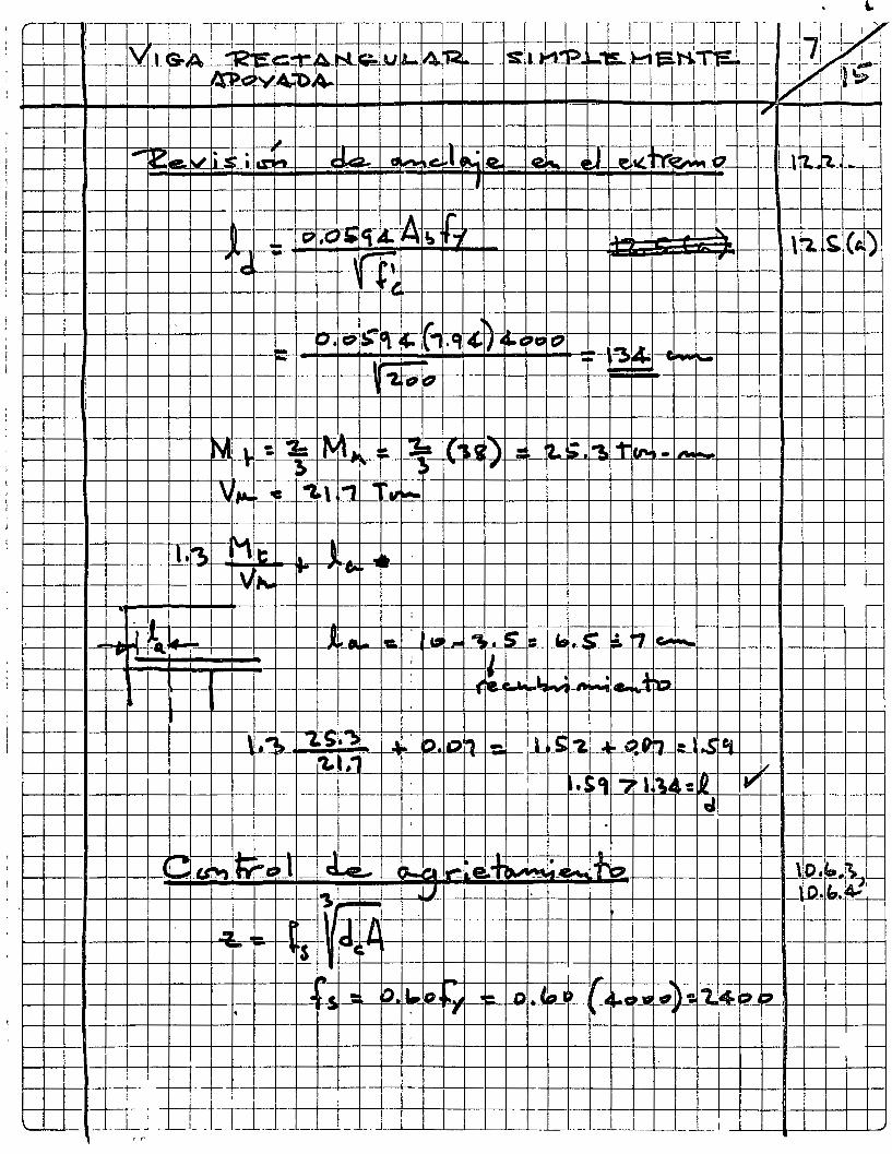
1----
'-------~----+--+---t-1: .J-c 711, "' 11• "' "' ~ ; ·~ • ¡u -~-' ., ... 'a "' ¡;: ~-+--1---+---lt-----t----r-r----r------1
---LJ-W-J-+++--t---'H-tlil
Llj_~-1-+-f-+-~t-f~~-t~rt-rttL~r--~:L~·J-~+·~~+4-r~-~~~~ r--~~~~~=tttt=tt=q;_c:~~~?_~~-~¡ar~:-:¡~-~~;r[-~~M-.r~;..~-~---~~~-~~t:oc.~rPF1fl~ ~-~g-~~-w_¡___r Cii\;~-.:-1-+"~'1.~tt~tt=l1=-t-=+q L-1----L,~-+--1--1---+--+---1----t-+++. -t--H-t-tlln~~rl----+----r--t--------+--1---+-+-t----t--t--a--¡--¡---¡
'P
1---+-+--j---i¡---
1-1"" -l"'l 1-+ l'i. . : 1 1
DC~+--\-~~++~~ttfi~rttt11~cc--~~+++-~~·~~~n
1
,
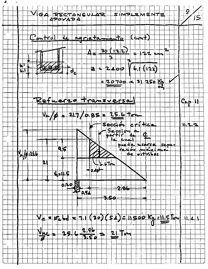
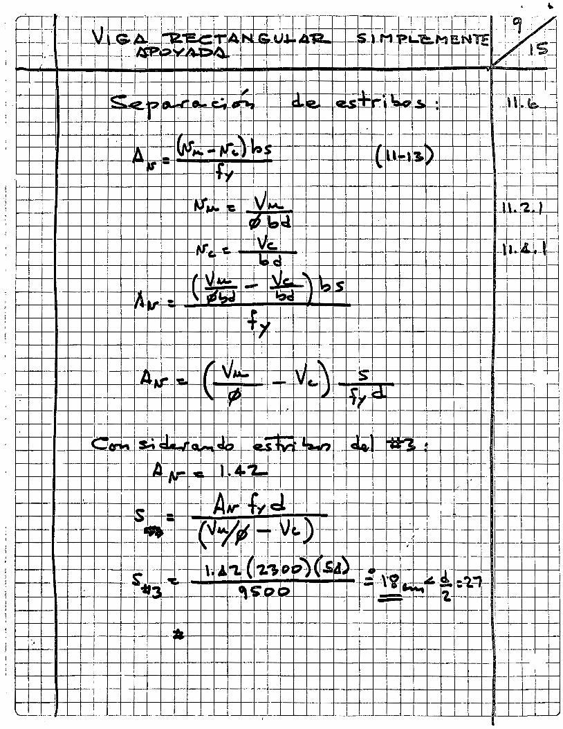
f--
-
- -. H-'-t--1-i---+-+-+-t-+-t--t---t-t-----r-l--1-----+--1 --1---+---t--+---.J----+.---+-+-+-+-+-+-1-+-t--t-+--- --1 ~~~~~+4~~-~~~~~~~-~-r~-r~~-~~ f--~-+-1 --+--l-r---i
; ~4-~~~:~-L~~~~~~~~~~~~~~-r~~~B-t-rTII i
f--+---1--1--t-t-¡ -- -
1 1 - 1-t----+-+--+---i
! l ~_L~~ -- -•-- __ -- L__L--"--- '--- --- '- - _ _J._'--'-- -'---l -'-- -~- _ _l__l.__L _ _L_L__L___l__L__j___J___L__L_______¡__---'---'------'--1
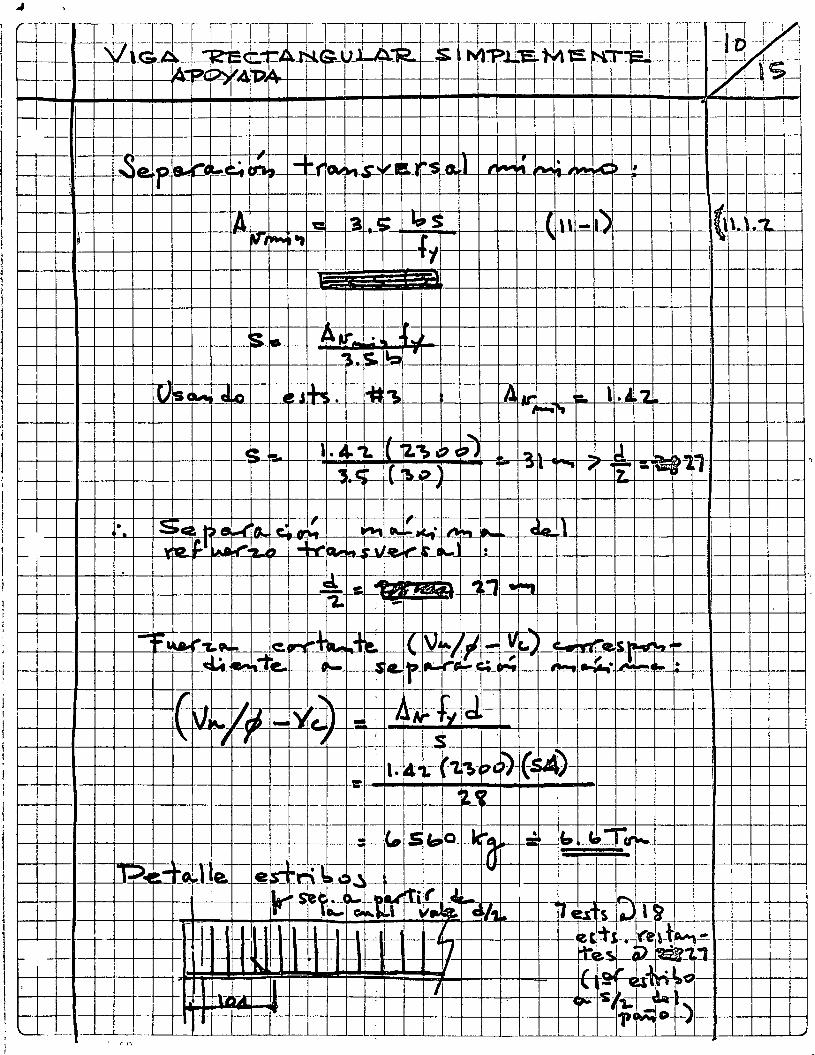
'\.
i!H-1--H++t---+-1--WUD--P-·,.~~ .. , _r-v'-.. -," ..... -,,L ,,, 1
, '' -'¡.. 1• jn---t-++--t--+-LJ · ·-r .-........ , .... -:aJ:=Iillt: •· íítf-HH-f4-++l~+¡¡ttUD
·.-
'Z. , •
,.
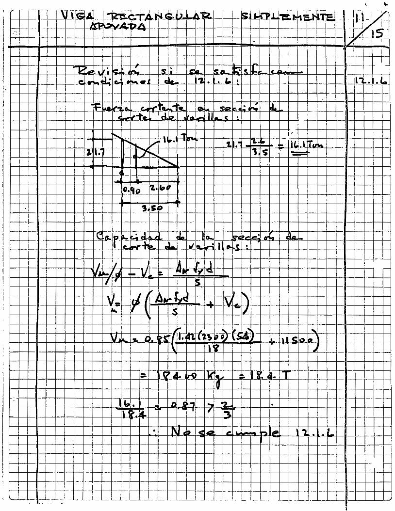
,... - --~---¡ r-\'' --- s¡ l 1 ,-- , -e: ~---T n.· ,¡,. -~ '~- ~ M-:2 .W-.i r-h ii.~T:el -~~ '-- -A! __ t_::R'i!. :TA- -<~ -¡ 1 1 1 1 1
~EE-1--- 1 ~ 1-- ---- -~~1)4 -¡ -
1 +- l --f-f--- 1 1 l--
1 1 1 '
1- ! ¡ -
l· J
-~ ~~ -"-¡,• ~- -, s __ ¡_ a.. ls_l ~ ~S- ¡.¡;. l#
~--·- f--,_. F--
~ 1-r el. 1 "'l_ ~ 1.:1 ~-!'_L._ la ~ ,_~,..._~
~;[]··~ • • • --- --
--1--~ 1~-f---1 ' 1
-~, ~ ~ .. ~-~ _ la e ~. ~. ~ ~ 1 i 1 ~Z:---~ dt: .... C2 --
1 ll.a!.foool IJ le 1
c-"~te.~ 1 .. .
~' --l 1 1 1
'~· ,__
¡¡. .1; ~' -1 -
1~~ 11" ~ r.j ..._ ' 1. ' 1
2. '· 1--· 1 . .¡ A ¡¡¡¡¡¡¡ ~ - ---41 f"o,~
"
~ -j 1
---1 '1 .~~~-Q
··¡1.-; .,,. ., 1~50 !
l i;:1:;1~[u ~.. ~ 1 -
tl~f rwo .... ~,_ cia. 1 a... ,_.
11' ... ... 1
1~ ~ ~ ~t.. 4CI. ,.; l. ,J.t • 1--1 1----
í 1--- -1--
! "~1¡~ ~ r l .-
·~ IV:. :. · ~ ""/ IQ.
1 '{' ¡¡¡;· ¡:)
• ¡, l. 1 '1
r/k. ""-~~ 1 ¡A~f~tt ..L ~ -= 1---- -j-¡ - -~ - "T .._.
f-- - -T
lYWo)-f~ 1 r 1)- ' vj L. ~ ''• . f-SC~ ~-;1t -~
...___ ,_. !: 12 ., ,\
\1 U'l ' ~
1 ---- 2-4 ... In: )( ia ·:. 1 • • 1- 1 lrf --
1 l - -- ~-~'- ~ 1 ~, ~· 2.- • .
¡¡ ~~ • .. 1 ¡::¡ --.
• 1' IJ ti ~ < ~ ,. . P- 1~ , &
r¡__ -'
t--
~---1--1 1 ---_e --~----- --- ~--- 1 --1--1---- ---- 1 1 =l_T- +-- --, ' ' __ ~___l __ _ ______ L ____ ; -- '--- ____ ¡ -- 1, ________ _j_ __ L. l__ - __ l - - _!_ -- ___ j_ _ _L
' . ' -- -
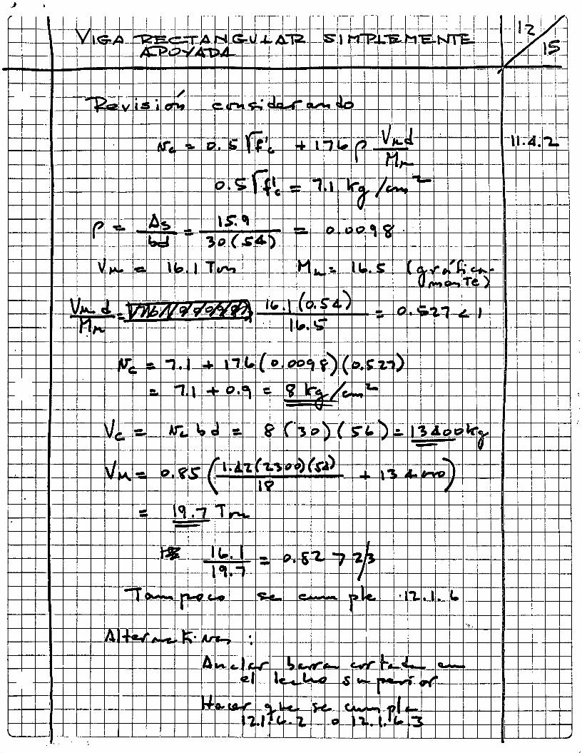
-,, _,---,-..,--,---,1--,-,---,----,--,---,---,--,--,-,--,-,--,--,--.---r---,.-,-"--,--.,-,-....,--,-----¡--.---,----,----.lc--r---.-Jir-, --r--r........ 1
1 ~ ':lt -¡¡. 1 ~ " ., J rt·-----~--t-:-:-:::~+=_:__,_;=-_:_,-~::~:~.::=: 1
l--+---1--+-f--!f-+-+-t-+--t--+ ......... -rr -~ ~~ --~ ~ ..J.,~ .,.111 , ~+---+---~l---+-1---1--11--
f-+-t----t--t---t-+-l--t--1,~ ... --r_l-¡;~-"-1 ~ ~ n ~r -r~ .--1--1--+---l-+--+--+-1--l--+--1--t--+--ll·--
¡ r-r"D r-r ~--~ J~ r-=r ..... ~1 'í J..l"?--...,¡-...,. -~-~~--1--t-+-t--+-+--+--+--t-+-t--t---t-1
1--+--1--+--t-,1-+--+-+-l-+-+-+-t--+--+--+-t--+----t-t--t-t--r-:---, ~-~ ... ~ J) • .. 1-r" .r-'1 ~ ! 'ti 1--+-~~-a~~~~-+-+--~-~-+-~-r~~---~~~-1-1---+~ ·'~.
~~---~-¡
lA
~--·rt-~ F·:.n---+-+-~-+:-~-+·1:n-~~--~-.., c. .,. . •!lr_!'!'!s .. +--t ·~=--+--+-.,+=r.J=-+---+--+-+---1f-+-t-+-•--+-+--i r------l--1-+-+-+---+-+--t--t--1-
-~ =1·----r-~-+--+-t--t--t--t--1--t--t-__ -t_-1 , :
t 1 .L .. ~-1
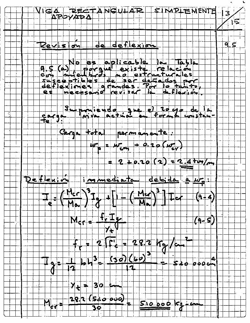
1--+---+--1-1---+---+--+-t-+--+--t--+-+-1-+-- ----- - 1-·--t---t--t--+-+-+-+--t--+--+---l-+--+--+-f--+-~-1-+--+~~
1--t--t--ll¡-+--+-+-+--+--+-t-~,-lt-~--- -3·tl·-!-lll~ -~.:-J--1 ---11--t--t-+-lr-t--+--+--f-+-+---l-+--' -+-_¡__f--+-i
1--+---+--1-'--+---+--l-!-+-+--+--t-+-- -+-~--f---t---t-.!:-+--+-+--+-+-l-+-+-+-+-~f--+---+--t--1, --f----i-1 -+' -
~---+--+--•-+-+--+--~~ -+--t--f1;~; '\ ~~S~L-.:~~~)1-t-~-+-+-t-+--+--t-r----+---t-+-11---+---+--+-la-+--l--+-+-1 1-+---+-11-+--+--~¡M¡ ~ : ~ 0 1 ~-+_JI~S~+'~-0~---~-o~-o~-e~>--!-~--~.4~~fU-~~...J-.... _J__U-!I-+-+--+--+-I 1-+-t--•--+--+--r--+-t-t--+--+-+--+---+--f"-,- -+--1-, IT " '--'-__J__·I----'---'--'-- _l__j_ ___ - LL_¡__¡__J - J_ _ _L ·.-'--1.--'---'---'-.L T - 1 __ __L.--L__J__..L.........J. L__¡_--11-..J.__J'----.l_--1......'
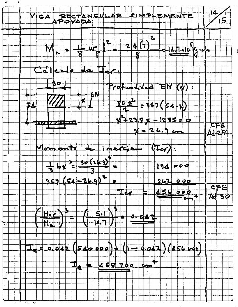
l
i ! 1
1 - .
-~· da •' -~¡:-·e!» '·s ¡·p f-1-,-=+~-+-a __ Lr.~-+--+--1---1--l---+-+--•-+-+---t 1!---!--,:-+--+--+---+-+--+---+---+-
1-+--+-+-+-t ~ . .:! ¡:Le rL ,Cil . :7 1-•l )~ :t:l :o c:un:~:v~ )-+-"'"'-+~ 1'---tl---+-0' Cl+-+11--+-~-L. .... -,._._-+--t---l

!
1 '
_¡ i
1
1 1
;
' 1
cr=t=t
to~l
lr:l' -
rt-t-,
t-t-H,
-+,~!-
+ 1++~~~-
-·+l-i
t=, ++
;++~
=++~
~~=r
=rrr
:c¡'
Jt:It J·
:r 1:r:,~ ¡--
__ --~-
--T
-+-t
-+--
+-_-
r+,,_
-----~ 1f--+__
_L_-~~
~-+-+:
-+-t--
+--l--
-l'~ -
L-'
1 1
1 1
1 r
----
"f ·-
· -r--r+-t--t--+-+-+--t-+-t--l---1----:~
-r--+
-¡-
-t--
-t--
-t--
t-r-
+-+
¡ -+
--t-
+--
-t.:.
..-LI
-1---
-t-r -
-t--
!r-
r----
--
'-----
--L-__
,____¡
____¡_
__i__l
_~~.J_
jL..l_
_L_Lj_
j___L.
Ll_j__
LLl __ ,¿f
tlr .JL
L-I
_L
J_j_
[IIJ
iro
:n
1 ,
1 1
, ---¡-
~---~-
~=~ __ ,
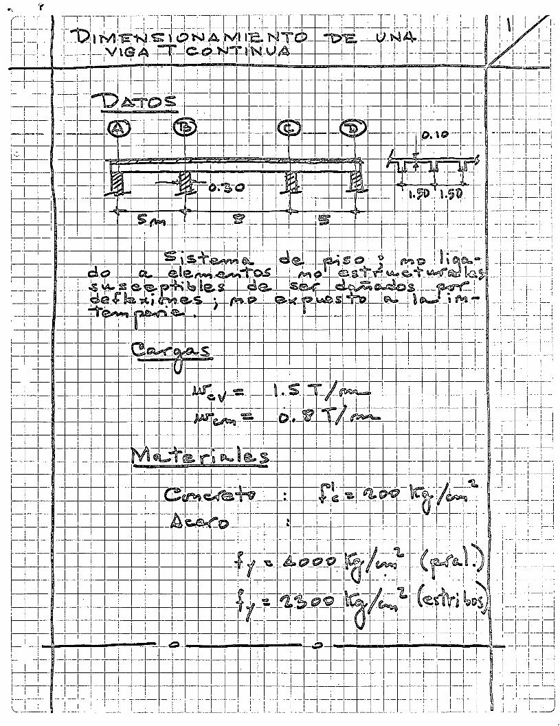
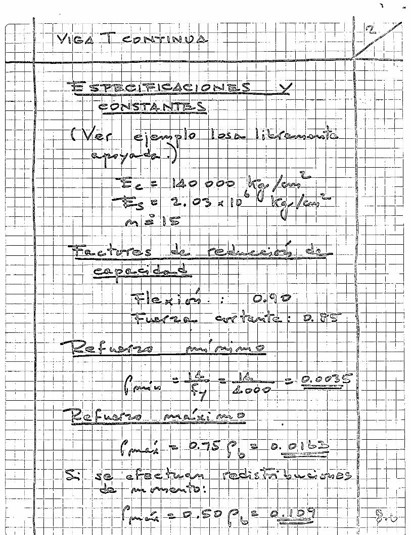
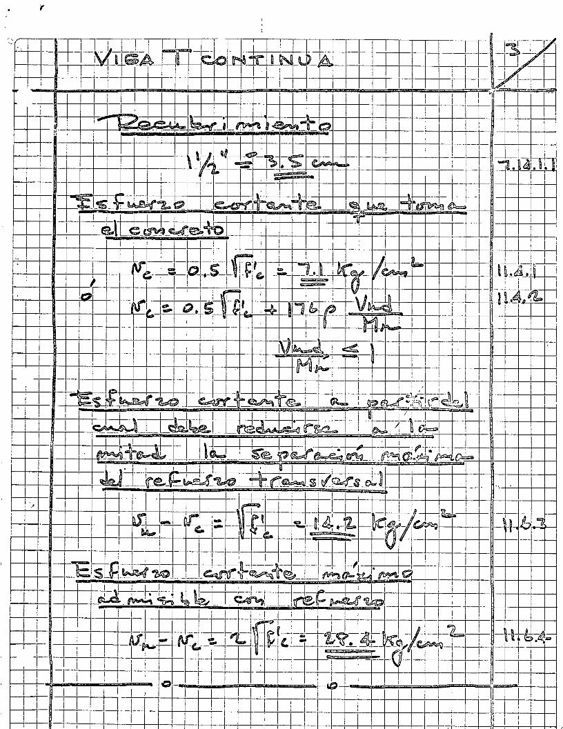
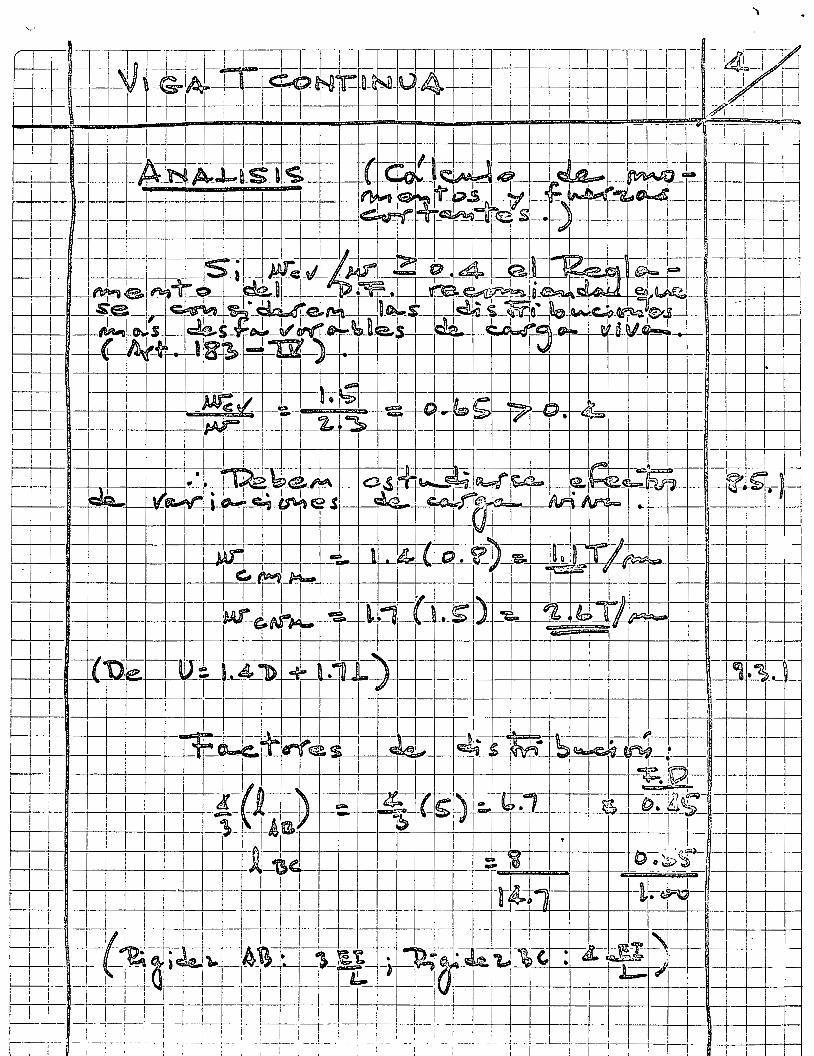
-~+-r~-~~-~--~-~~-
1 L--~+~
'
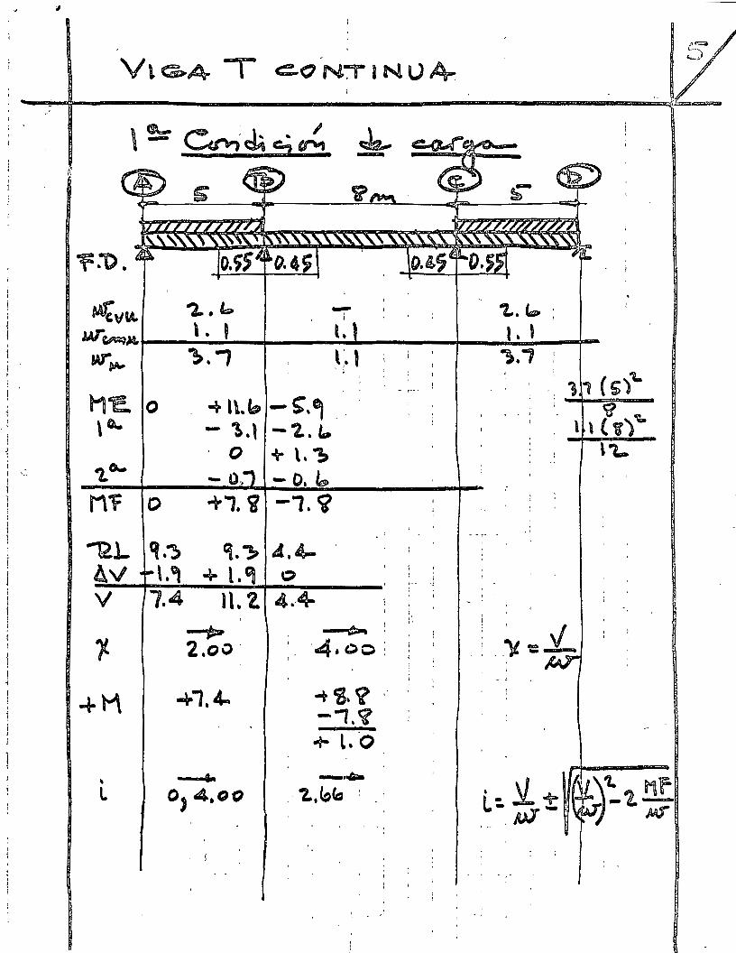
1 •
1
y:;o.
~\1~ "2...~
w-~~ \ . ' w-~ ~ . ., ! ' l M1:. -+ l\..b o
\c.. - \.l o
-.: ~o-- t).
Mf o +1. i
"'12L q,~ '}. ~ AV \.G¡ ..... \." y 1.4 1\.2.
~ 1- 2.oo ·
+M -+1, 4-
\ • L o, 4.oo
' í
~ ¡
l.
Lt ' 1 ¡
'
-S".~ •'. i
-"2.. ~ + \. ~ -o.~
-1. ~
A.4-' o '
4.-4-~
1
' ·4.oo:
-+ cg. <l -1.~ + L.·o
-·· '-z. b~ 1 ' .
' 1
' ' '
' . 1
: '
: ' : ·--:
1
,.
' ' - '
"L.~ ;
L' ,.,-, :
' . : 1, ( 5),_
· · : , , r,) oq.
\1.-
' ''
) ' . 1 . 'V - V
. ' . _¡¡. --1
- "
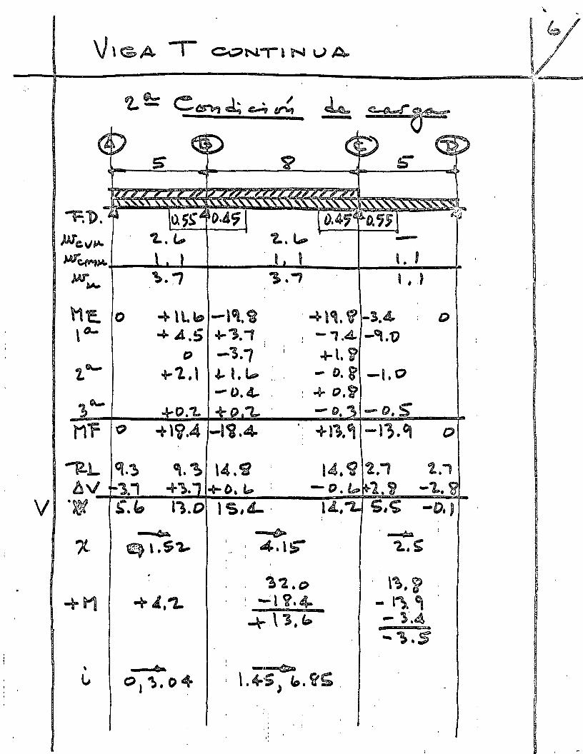
\¡ ~
1 ~,6/
\J\GA 1 ~NilN \.JA. /
--~------------------------------~,./
)Jle-v~ W"'~
w~
l1a o \o-
t"'-
~
M'F Q
'"12-L q.~
b\1 '3.1 V ·~ ~.b
?..~
' l ' ---Ll
-a.\ Lb -lot. ca -+ A .S .a- "l. 1
o -"3.1 + 1. , \ .&- l. lP :_ '
~. ~ '". ~ ' +~. +O, 4P ~
11.0 l s.L..
' ~ l~. V -3.4 ; D ! -, .4. _,.1) ~\.V
- o.&' -1. o : .,._ o.S? --o. -o. S
·: + 11. ~ - r~~. ct
l4. CJ 2., 1., - C). fp l.~ -"L.~
~~.C) -:1 V.4-
\~. ~ - l~. e¡
~ \ '3, b -l·.4 -~.s
1
1
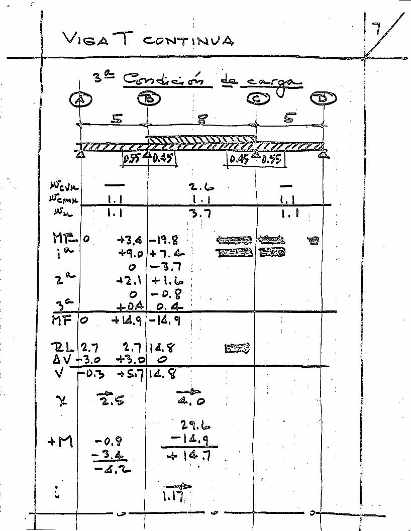
! ' 1
'
,_
-
,. 11
14Tc.~~ )Afc,~,._ »1.,._
Hf!. ,~
"L. ;e:.
Ml=
tl..L. llv v )!.
+M
' L
-1.1 Ll
o -+"3.4 +Gi.P
()
-'l.\ o o A
o -+ 14. ~
1.; 1..1 "3.«' --~-~.o
O:?> -+S•1 -e-' -a..-.;
-0.9 - -s.~ -4.'1-
1
. ¡
1...t- -l . 1 l.l ~., 1 • 1
í ' :
' ' ,
-l~.c¡ : ~kiil ~ +1. 4-
l
~~ tw• :
-~.1 1 ¡
: '
+Lb.; -D. S1 /
:
o. ,
-I¿,GJ ' 1
}
lA. <l ~ o
lA. <¡'
6a 4.Q
'~ 1,.~
-l¿.~
4- \~ :1 --: ..
-~~ \,\1: :
' ¡ ~ .,p ~
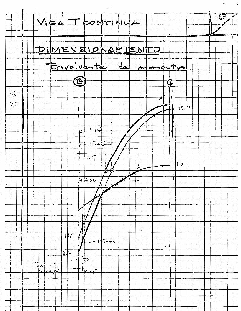
~-+--!-' -+1 -+1-+-----+-l-' _ _¡_l --1-l-r-t-1--~--I_L!.--1+ --TI 1 __ _j _ ____¡_i -+! _Ll_L+_L__L _ _J_l_ l-+--+--t---+-t--r--t-'--t--t-!-+-----+--+--+--+--t-+--+-+--+--+--+-+---1---l---l·--}--+--f---I-H-.Ll_, J_L ! i '---+--+--r-t--t--r--t---t--t-l-+-----it---+--t--+--t-+--+--+--+--+-+-l----1--+--l--+---l-l----l--+-+-¡ Lj i 1 1 ¡ : ' l -1 ' 1 1
~-+--+-+-+-+-+--+---+----t--+--11--+---+--+--+---~-_¡.._._-+---~--J--+-I -l----1--l---+---~--.1·---1---~---+-·L;_ '--~~ _ -+-L -1--t---1--+---+-·1--+--+' -+--1-1 j ¡
: -·~-+---+---+--+--+--+--+-1--lt---+--+--+-+---l--l---l--+-1--+--l--+--+-+---+L-11 W+ : ; 1---t--t--t-+_--+-r-_-+-,_ _-:_-+-t--+-t-_-:_--+-+--+-+_-tt,-+--+-:-:~=::~:=-:_:~.~~-+-~-+-if-o~_t::,__ cV: '\"<= ~h-t-j_¡~ 1---t-~lt---~~~f~~-~J~~~~--+--~---1-~~~=~ .---·~~ 1
1
¡ ¡ 1
-¡..,¡ lL ~ 1 ~-¡c--f ~t--~~ 1 1 ffil¡ .~ 1¡
[-+---+-+--t--i' -t-+--t--1---4~-+--t---+-!-t--t-+-~-1--i-~ 1/ ~J;'j 1 \ 1 1
~~~~~~~~~:-~~r-~~~·{ ' 1
~++~~+--+~++~~4--+~~~~+41/~~V~+~----~~~--+-~~~-B~I~ l---t-~r--+--+-+--+-+--l-+~-f---l---+--t-~-l--+-+---l-+-~-l~~'f7· --e-~--+--+-----1--+-t---+--+--+-!
"" v v_ 1 1 -. 1 ~---=2' -"" J, .. q .. z--e> ~
\ .,
1\-v 1¡' ~~-+-r-+~+--+~~-n~~·~'~--+--+-+-+--+-+-+--~-~-+--J-+4-~-+--+--+--+--+-+-m-L-r
~-+-t--+~+--+~~-H'~lt--··~--+--+-+---l-+-t---1-~---l--+--~l-4-~-+--+--+--+--+-+-g ~~~ IJ 1 !
~\

..

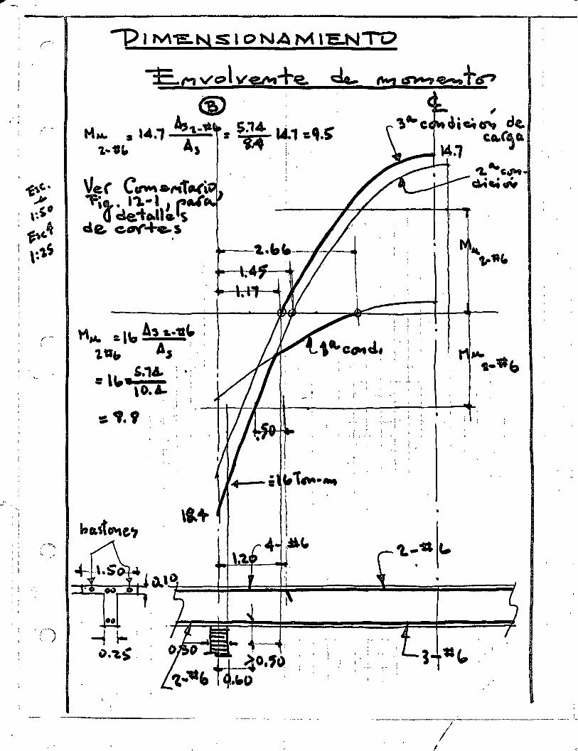
1
--------------------! ____ _ '
... ' 1
1'
'· ' ' ', . ' -,· ' ! . 1
1 • ' 1 1 • j
r 1 • ; • 4--; ~ . ~ -' '
1 ' "
,l ' ¡ ' ¡ 1
-·r . ..,' --\ ~ 1 1
., ' .
1 :
1
'-•
+1\
l
1 .l
',~.(1
: -; r-
! ~ .:, ·o' ' aata . :. : "VL., -,
:. , e, .,At : , ... , ~v ~~~ -w~
_ . .,,. . .,._ .....
. ; e 16·1.
.s·L·-• .~ t:A • \' L••t e .,u v• .. ~· ?L"S • -.·1.'V r .-..
.el)
(' '
"-.. -'.
? 1
. 1 l ' 1
', '
' 1
r. 1 ' -,
! ,'

..... '
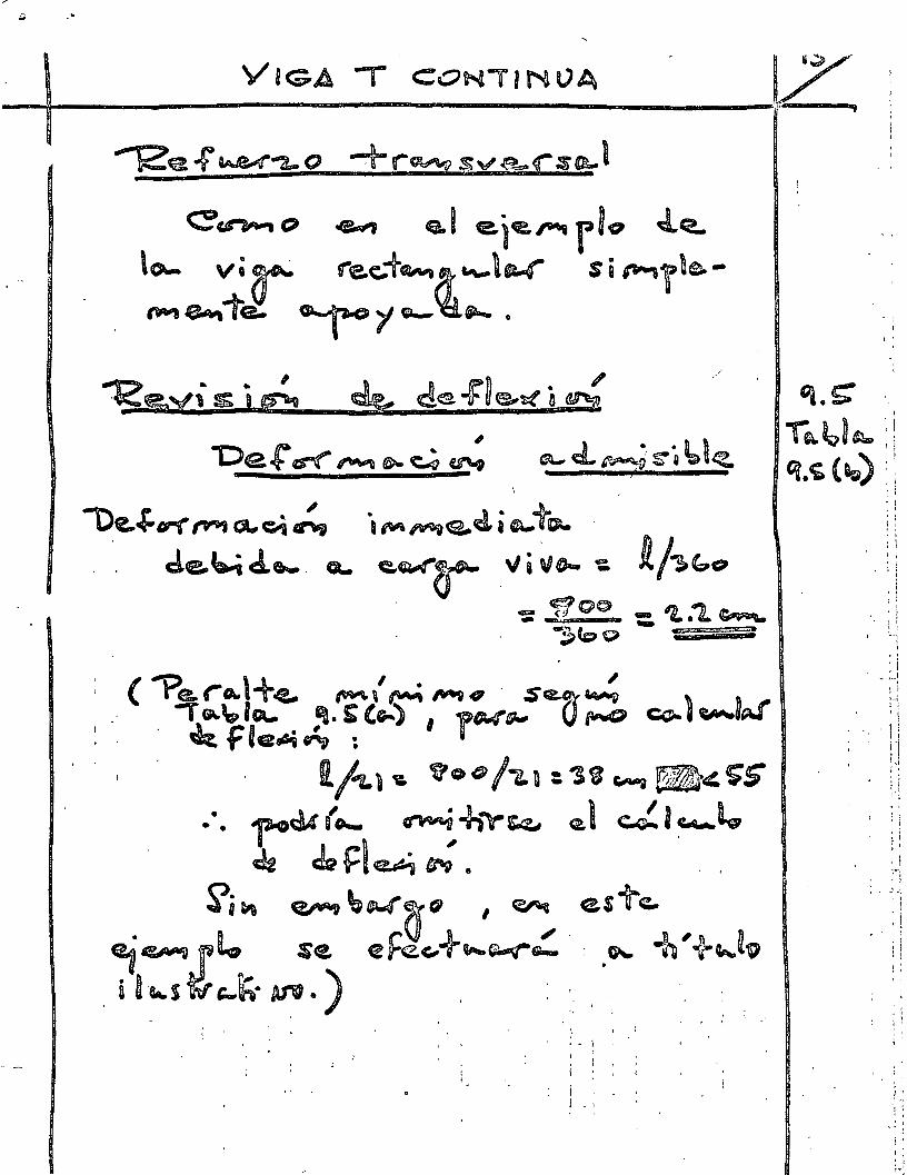
(,\
l\
,<f
':)
t.
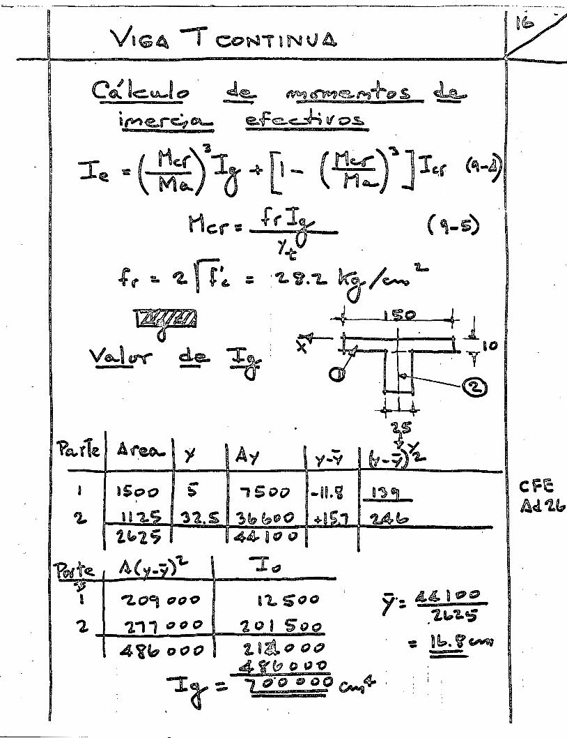
-
J
a '~' 1 \\
¡d c-1
-:.t
., ~ f-1. :!
-------~
----.
·'' ,.
·~
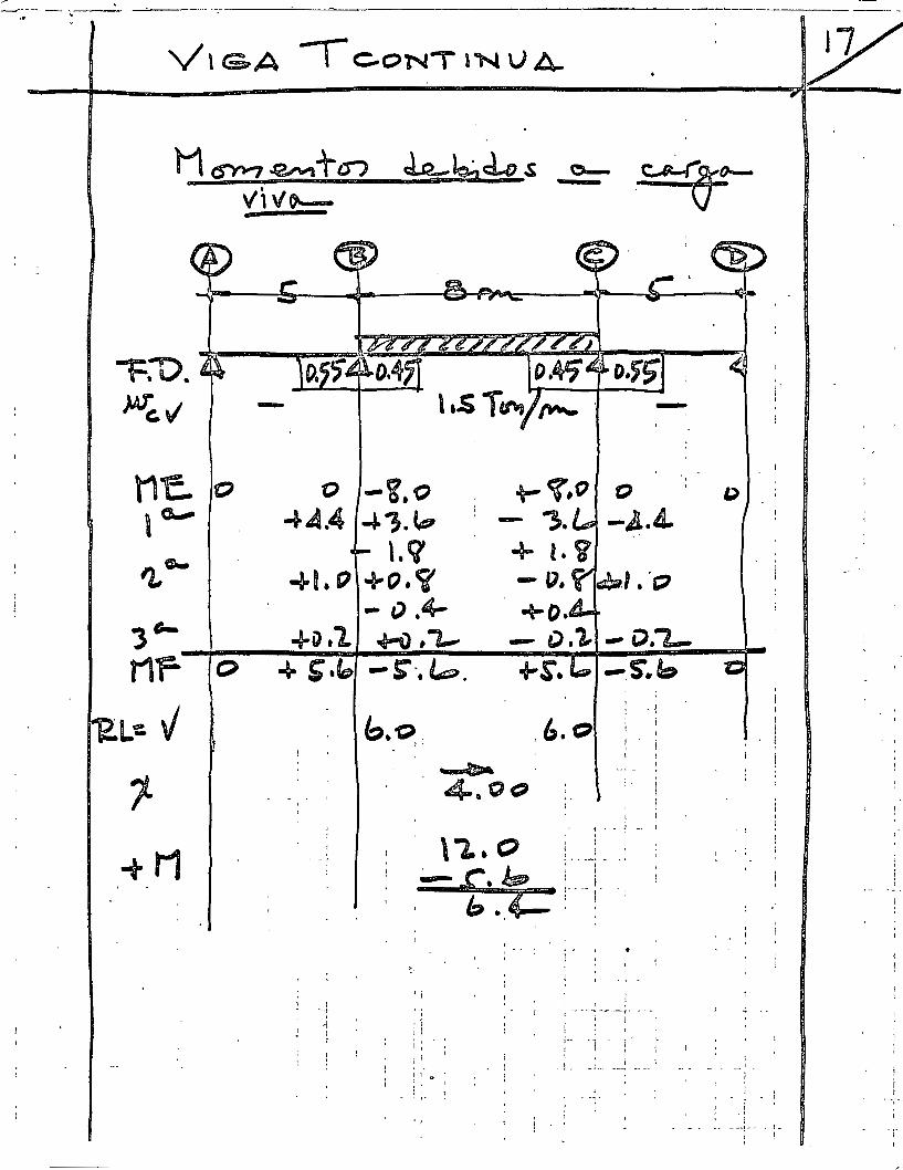
1
1 -
/C
1
i l -: ---:---.. . --
' ' 1' ' ' ! ( ¡ . t --'
: 1
' -~--
1
. ~. ~
' ' 1
; --~-· i-----; ~--; -l l
t ' ¡ ! ;
, 0
1 l -' 1 1
' ' ' 1' ' -~ '
1 ! t 1 ; -, '' --.. -·! : '
1
.. +
1-
, 1 ; l '-----¡-------~-~--1
1 1
-. -i
' 1 ' 1 1
' .. 1
1 1 1 1 ~ f
'
! 1
!-r--I
¡ ; :::!'. e¡ -1
·¡---·; ~ .,... __ ( \ --, ..-1 '
: -. ;----¡ o . t. \ --f --•
1
1
-i
1:3 .• ,.
., 1
' 1
:o·q
·~'·.S-")• S + ...,_,M l.'Oi" _,.o -A'tt+ ~·lth '\ ~ ·t 1-,,.,.,..
o·~-o
w+-t
/' -=-1'
~w -11t
-o 'ti
___,\ o -;J. U
-----------~-~--------~--------~-------~ --'\ ---__ :_-__ _ ........
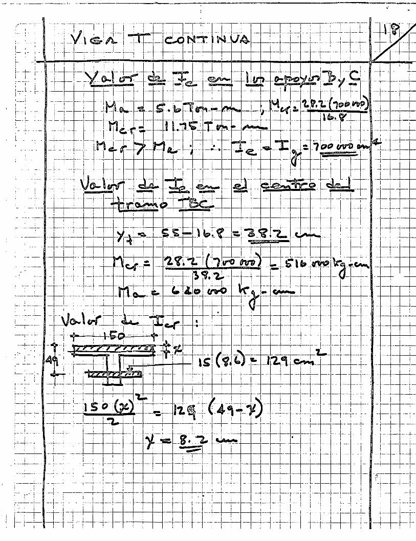
f~·:-
;-:·
-¡-·
; 1
1 l--T·T··r··-¡-·-¡--T--~
r··:
·:;.
ir
·:··¡
r ·¡
'-
--
' ,-
-,-
----,
• -,
-r-
·,'·
T·T
-1---
:-¡---
-r--
-,--
-1
~-:
\
-----
-¡---\.
~~----¡
--·r-·-
1¡----!
---¡-
··r·--¡--
-¡ --¡
--¡ -
t --,
. --t-
-! -¡
-1 .
¡-1
¡ '
' ! -1,
. r' -_
·,:
!·,:_-·.·1
: .
!.---_
.·, __ -_-
1! ..
• ·, -
1 '
' '
-·-
-1---,.
: -. ·.'-
-r,·
---_-
t : __
-_. -_ 1,--
--~ _·_;
---
----
;,-·
-¡.·
---.
-1,
·----
--!1-
---1,,
·, --
~-·,
-, .• ,---
-•. -
f -
--,,-
!"
1 ·¡'
·---¡
-¡--
_¡!_
!, --¡
-. -
--
-_ . .
....
--
--.
--
.. -
--: ..
--
-.
' '
' '
' '
' '
' !
: '
' '
' !
: '
i
•.
f '

.~
-.,.-,.:--=----___;¡__--,-·---·
Vigas Continuas y Losas Reforzadas
en una Dirección
Empleando el DRU
9.1 TIPOS DE CONSTRUCCION
9
La mayor parte de los miembros de concreto reforzado son estáticamente indeterminados, porque son partes de estructuras monolíticas. Sin embargo, parece que se tiene la impresión equivocada de ignorar muchas formas de construcciones precoladas que están formando ·una parte importante del mercado actual, que varían desde canales para pisos estáticamente determinados, secciones de doble T, y de otras formas, a sistemas en los que se combinan las unidades precoladas con trabes coladas en el lugar o con losas, para formar construcciones prácticamente monolíticas o compuestas. Con frecuencia, los elementos precolados son también preesforzados.
La forma más usual en la construcción' de edificios consiste en losas que se cuelan monolíticamente en los piSQs de los entramados que trasmiten las cargas de los pisos a las columnas. La vista en planta de un piso de éstos, en la Fig. 9.1a, permite dars~ cuenta que estas losas están apoyadas en los cuatro lados y que podrían proyectarse convenientemente empleando refuerzo en dos direcciones por los métodos del Cap. 11.
Cuando una losa tiene una longitud mayor del doble de la anchura, generalmente se proyecta como losa continua reforzada en una dirección, pero añadiendo acero especial para los momentos negativos en dirección transversal a las trabes, como se dijo en el Art. 906e. • Cuando se proyecta una de estas losas para soportar una
• Debido a que encuen!Tan mb sencillo el refuerzo en una dirección. mucho> ln¡;eDieros proyectan as! todos los tableros. excepto los que son casi cuadrados.
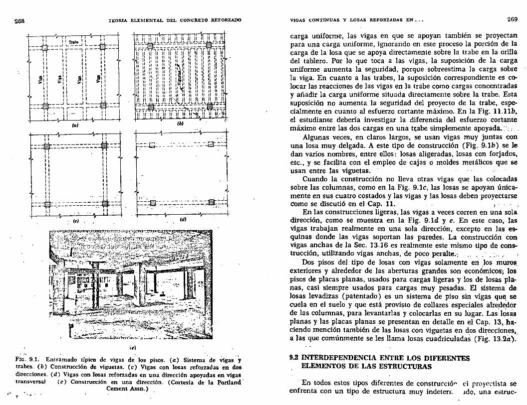
TEORIA ELEMENTAL DEL CONCRETO REFORZADO
. 11 \ITr&bell r 11
---t!-+--.J L __ _¡ L--~----*----, r---, r---w---11 :: 1: 1 11 11 11 1 ¡. ll 11 11 1 11 11 11 : 11 1 1 1 1 11 ... 1 11 ""1
.§11 .!!'1 1 JI 1 .:1'1 ""•' >1, ~>'11 >1
11 11 1 1 1 11 11 11 1 11 11 1 1 1 11 11 1 1 1
==*==~ ~::::; ~=:.-$:.:. 1 l_ 1 l. •• 1 1 1 1 11 11 1 -1 1 1
• (a'
,. ~ ·J --~------------JJ.-- _::·r~·-- _::.- _._ -_-_._ -_ _-_.-~_::, --~-----------~-- ~
' 11 1 - 1 11 • 1 1 1 1 11 1 11 1 1 1 1 1 1 1 11 • 1 1 11 • 1 11 1
1 11 4 • 1 • -- J,l _. ' ; '. ' - • ' ' -~ ::-M-:::.::..::_:·_-_:._:::-::f¡t:.:.j ==·----·_:_:_-~:..-_:::.:: .. ~·;.= -w-- -- 11 '. - -' . .• ----
1 l-l "' ' ._ .. \r 1 1 • • . ' 1
(ci (d'
íe\
Fic. 9.1. Entramado típico de vigas de los pisos. (a) Sistema de VIgas. y trabes. (b) Construcción de viguetas. (e) Vigas con losas reforzadas en dos direcciones. (d) Vigas con losas reforzadas en una dirección apoyadas en vigas transversa) (e) Construcción en una dirección. ( Cortesia de la Portland-
Cement Assn.) --. . ...
VIGAS CONTINUAS Y LOSAS REFORZADAS EN •.• 269
carga uniforme, las vigas en que se apoyan también se proyectan para una carga uniforme, ignorando en este proceso la porción de la carga de la losa que se apoya directamente sobre la trabe en la orilla del tablero. Por lo que toca a las vigas, la suposición de la carga uniforme aumenta la seguridad, porque sobreestima la carga sobre la viga. En cuanto a las trabes, la suposición correspondiente es colocar las reacciones de las vigas en la trabe como cargas concentradas y añadir la c'arga uniforme situada directamente sobre la trabe. Esta suposición no aumenta la seguridad del proyecto de la trabe, especialmente en cuanto al esfuerzo cortante máximo. En la Fig. ll.llb, el estudiante debería investigar la diferencia del esfuerzo cortante máximo entre las dos cargas en una t:tabe simplemente apoyada.:·: , .
Algunas veces, en claros largos, se usan vigas muy juntas con una losa muy delgada. A este tipo de construcción (Fig. 9.1b) se le dan varios nombres, entre ellos: losas aligeradas, losas con forjados, etc., y se facilita con el empleo de cajas o moldes metálicos que se usan entre las viguetas. ·
Cuando la construcción no lleva otras vigas que las colocadas sobre las columnas, como en la Fig. 9.lc, las losas se apoyan únicamente en sus cuatro costados y las vigas y las losas deben proyectarse como se discutió en el Cap. 11.. : - . . ,
En las construcciones ligeras, las vigas a veces corren en una sola dirección, como se muestra en la Fig. 9.1d y e. En este caso, las vigas trabajan realmente en una sola dirección, excepto en las esquinas donde las vigas soportan las paredes. La construcción con vigas anchas de la Sec. 13.16 es realmente este mismo tipo de construcción, utilizando vigas anchas, de poco peralte.; ... , . · . : .. _,
Dos pisos del tipo de losas con vigas solamente en los muros_ exteriores y alrededor de las aberturas grandes son económicos; los pisos de placas planas, usados para cargas ligeras y los de losas planas, casi siempre usados para cargas muy pesadas. El sistema de losas levadizas (patentado) es un sistema de piso sin vigas que, se cuela en el suelo y que está provisto de collares especiales alrededor de las columnas, para levantarlas y colocarlas en su lugar. Las' l¿sas planas y las placas planas se presentan en detalle en el Cap. 13, haciendo mención también de las losas con viguetas en d_os di~eq:iones,, a las que comúnmente se les llama losas cuadriculadas (Fig. 13.2a).
9.2 INTERDEPENDE.""JCIA ENTRE LOS DIFERENTES ELEMENTOS DE LAS ESTRUCTURAS
· En todos estos tipos diferentes de construcciór el proyectista se enfrenta con un tipo de estructura muy indeterr. .1do, una estruc-
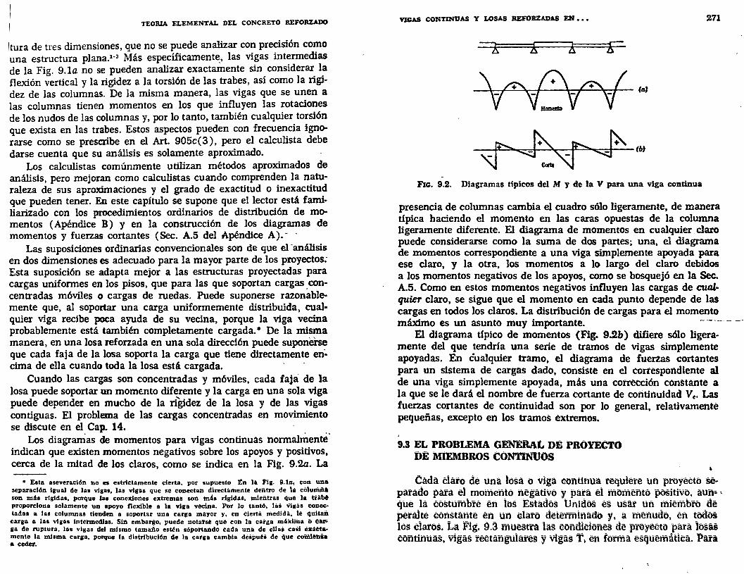
TEOlUA ELEMENTAL DEL CONCRETO REFORZADO
tura de tres dimensiones, que no se puede analizar co? pre~isión co~o una estructura plana.l-3 Más específicamente_, las VI~as mt~rmedias de la Fig. 9.la no se pueden analizar exactamente sm, cons1derar. 1~ flexión vertical y la rigidez a la torsión de las trabes, as1 como la ngi
dez de las columnas. De la misma manera, las vigas que se unen a las columnas tienen momentos en los que influyen las rotaciones de los nudos de las columnas y, por lo tanto, también cualquier torsión que exista en las trabes. Estos aspectos pueden con frecue~cia ignorarse como se prescribe en el Art. 905c ( 3), pero el calculista debe darse cuenta que su análisis es solamente aproximado.
Los calculistas comúnmente utilizan métodos aproximados de análisis, pero mejoran como calculistas cuando comprend~n la n~turaleza de sus aproximaciones y el grado de exactitud o mexactitud que pueden tener. En este capítulo se supone que el lector está familiarizado con los procedimientos ordinarios de distribución de momentos (Apéndice B) y en la construcción de los diagramas de momentos y fuerzas cortantes (Sec. A.5 del Apéndice A).- ·
Las suposiciones ordinarias convencionales son de que el-análisis en dos dimensiones es adecuado para la mayor parte de los proyectos: Esta suposición se adapta mejor a las estructuras proyectadas para cargas uniformes en los pisos, que para las que soportan cargas _concentradas móviles o cargas de ruedas. Puede suponerse razonablemente que, al soportar una carga uniformemente distribuida, cualquier viga recibe poca ayuda de su vecina, porque la viga vecina probablemente está también completamente cargada. • De la mi~a manera, en una losa reforzada en una sola dirección puede suponerse que cada faja de la losa soporta la carga que tiene directamente en'-cima de ella cuando toda la losa está cargada. · -
Cuando las cargas son concentradas y móviles, cada faja de la losa puede soportar un momento diferente y la carga en una sola viga puede depender en mucho de la ri~dez de la losa y de las vigas contiguas. El problema de las cargas concentradas en movimiento se discute en el Cap. 14. . ..
Los diagramas de momentos para vigas continuas normalmente indican que existen momentos negativos sobre los apoyos y positivos, cerca de la mitad de los claros, como se indica en la Fig. 9.2a. La
• Esta aseveración no es estrictamente cierta, por supuesto '!n la Fl(l. 9.1a, con una separación Igual de lea vi11as, las vigas que se conectoú'l dlrecumente dentro de la cólulñii• son mAs rlgldas, porque 1u conexiones extremas son mé.s rl(lidall, mientras qué la trabe proporciona solamente un apoyo flexible a la vi11a vecina. Por lo tantó, latí Vigaé coóectadas a las columnas tienden a soportar una carga mayor y, en élértil medida, lé qultaii
carga a las vigas Intermedias. Sin embargo, puede notar&é qUé con la car¡!a mllldma ó e• ga de ruptura, las vl¡¡as del mlsmo tamaño estén sóportaildó Uda uüá de éllai caiil éilliétamente la misma carga, porque la distribUción de la catga cambia déiipuéi de qué comli!ilia a ceder.
VIGAS CONTJNUAS Y LOSAS REFOBZADAS EN. •. 271
(al
Flc:. 9.2. Diagramas tipicos del M y de la V para una viga continua
presencia de columnas cambia el cuadro sólo ligeramente, de manera típica haciendo el momento en las caras opuestas de la columna ligeramente diferente. El diagrama de momentos en cualqui~ .claro puede considerarse como la suma de dos partes; una, el diagrama de momentos correspondiente a una viga simplemente apoyada para ese claro, y la otra, los momentos a lo largo del claro debidos a los momentos negativos de los apoyos, como se bosquejó en la Sec. A.5. Como en estos momentos negativos influyen las cargas de cualquier claro, se sigue que el momento en cada punto depende de las cargas en todos los claros. La distribución de cargas para el momento máximo es un asunto muy importante. - -- ---- --
El diagrama ti pico de momentos (Fig. 9.2&) difiere sólo ligeramente del que tendría una serie de tramos de Vigas simplemente apoyadas. En cualquier tramo, el diagrama de fuerzas cortantes para un sistema de cargas dado, consiste en el correspondiente al de una viga simplemente apoyada, m~s una corrección constante a la que se le dará el nombre de fuerza cortante de corttitmidad Ve. Las fuerzas cortantes de continuidad son por lo general, relativamente pequeñas, excepto en los tramos extremos.
9.3 EL PROBLEMA GENERAL DE PROYECTo l)E MlEMBROS CONTINUOS
Cada élaro de una losa o viga continua requleré uñ proyééto separado para el momento ñégativo y para él momento positivo. áti!i• , qué la costumbre en los Estados Unidos es usM' un !fiiembro _<lé peralte constante en un dáró determinado y,_ a ménu<lo, en ~ódóS los daros. La Fig. g,3 muestra las eonditioñes <le proyeéto p~a ~sü eontifiuas, vigas reetanguláfés y vigáS 1\ en fonña esquematiea. Pua
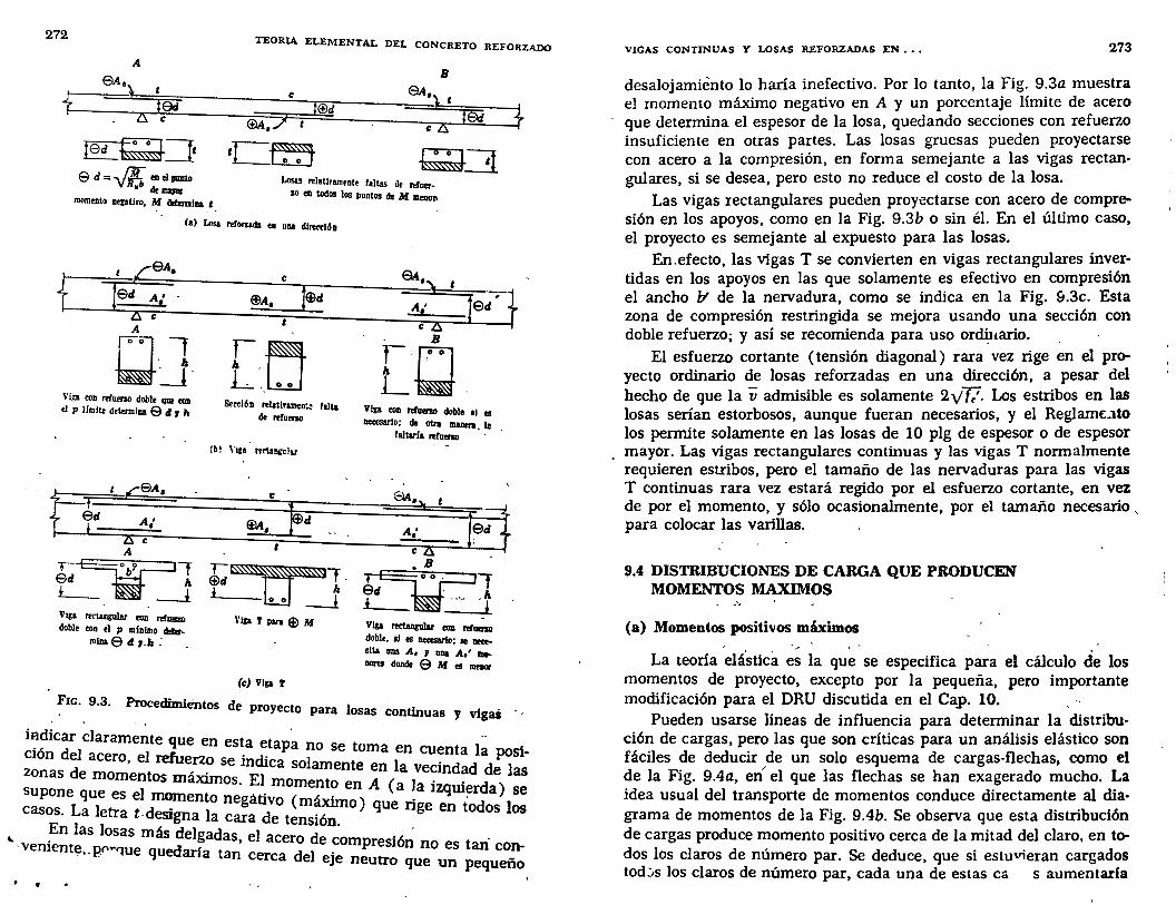
272 TEORIA ELEMENTAL DEL CONCRETO REFORZADO
f l9d ZS e
I§C~=tf
e t®d
ct>A,::I t
B
9A,) t
cLS l9d
e d = ..¡¡;, ea ei111DJ10 .. de
momento nepUro, M ~~!termina a Losas relaUramente faltas de !~!fuer
zo en todos los puntos de M meDOfl
fa) Losa reforzada en una dire«ión
Viga eon rerueno doble qur CUII
el p lfmite determina e tf J h
Vtga rectangular eon rehem• doble ton el p mfnlmo cltllr
mlna8 dr-h:
e
r_~ L._ld
s. .. ión relatlnmen~ falta de refueno
e
'u~· $d 1. l h
o o -l Vtga T para $ M
(e) Vip t
B
[Q Vip eon rerueno doble al 01 netesarlo; de otra manen. le
faltar!& refueno
• B .
?d~1 Vtga rertangular 1:011 !!faeno doble, si e1 netesarlo; se neeesita una A, 1 una A,' meDOrel donde 6 M 01 menor
Fic. 9.3. Procedimiéntos de proyecto 1 para osas continuas y vigai · ,
iHdicar claramente que e t · -· . , d 1 n es a etapa no se toma en cuenta la posi
cwn e acero el refuerzo s · di 1 -zonas d ' , . e m ca so amente en la vecindad de las
e momentos maXImos. El momento en A (a 1 . . d ) supone que es el momento negátivo (m , . ) . a lzqw~r a se casos. La letra t designa 1 d ~o que nge en todos los
a cara e tenswn. En las losas más delgada 1 ·
"'. veniente,- P~" .. '1ue quedarl t s, e acero de ~ompresión no es tan· con-. . a an cerca del eJe neutro que un pequeño
,
VIGAS CONTINUAS Y LOSAS REFORZADAS EN ••• 273
desalojamiento lo haría inefectivo. Por lo tanto, la Fig. 9.3a muestra el momento máximo negativo en A y un porcentaje límite de acero que determina el espesor de la losa, quedando secciones con refuerzo insuficiente en otras partes. Las losas gruesas pueden proyectarse con acero a la compresión, en forma semejante a las vigas rectangulares, si se desea, pero esto no reduce el costo de la losa.
Las vigas rectangulares pueden proyectarse con acero de compresión en los apoyos, como en la Fig. 9.3b o sin él. En el último caso, el proyecto es semejante al expuesto para las losas.
En.efecto, las vigas T se convierten en vigas rectangulares invertidas en los apoyos en las que solamente es efectivo en compresión el ancho b' de la nervadura, como se indica en la Fig. &.3c. Esta zona de compresión restringida se mejora usando una sección con doble refuerzo; y así se recomienda para uso ordi:uario.
El esfuerzo cortante (tensión diagonal) rara vez rige en el proyecto ordinario de losas reforzadas en una dirección, a pesar del hecho de que la v admisible es solamente 2y'f/. Los estribos en las losas serian estorbosos, aunque fueran necesarios, y el Reglamc.1to los permite solamente en las losas de 10 plg de espesor o de espesor mayor. Las vigas rectangulares continuas y las vigas T normalmente requieren estribos, pero el tamaño de las nervaduras para las vigas T continuas rara vez estará regido por el esfuerzo cortante, en vez de por el momento, y sólo ocasionalmente, por el tamaño necesario, para colocar las varillas.
9.4 DISTRIBUCIONES DE CARGA QUE PRODUCEN MOMENTOS MAXIMOS
(a) Momentos positivos máximos
La teoría elástica e~ la que se especifica para el cálculo de los momentos de proyecto, excepto por la pequeña, pero importante modificación para el DRU discutida en el Ca_p. 10.
Pueden usarse líneas de influencia para determinar la distribución de cargas, pero las que son críticas para un análisis elástico son fáciles de deducir de un solo esquema de cargas-flechas, como el de la Fig. 9.4a, en el que las flechas se han exagerado mucho. La idea usual del transporte de momentos conduce directamente al diagrama de momentos de la Fig. 9.4b. Se observa que esta distribución de cargas produce momento positivo cerca de la mitad del claro, en todos los claros de número par. Se deduce, que si estuvieran cargados tod:.s los claros de número par, cada una de estas ca s aumentarla
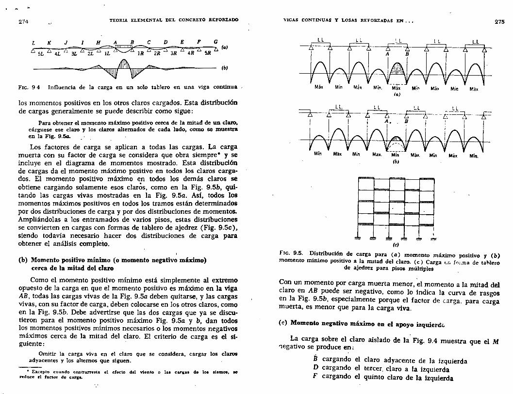
274 TEORIA ELEMENTAL DEL CONCRETO REFORZADO
Fxc. 9 4 Influencia de la carga en un solo tablero en una viga continua
los momentos positivos en los otros claros cargados. Esta distribución de cargas generalmente se puede describir como sigue:
Para obtener el momento máximo positivo cerea de la mitad de un claro, cárguese ese claro y los claros alternados de cada lado, como se muestra en la Fig. 9.54.
Los factores de carga se aplican a todas las cargas. La carga muerta con su factor de carga se considera que obra siempre• y se incluye en el diagrama de momentos mostrado. Esta distribución de cargas da el momento máximo positivo en todos los claros cargados. El momento positivo máximo en todos los demás claros se obtiene cargándo solamente esos claros, como en la Fig. 9.5b, quitando las cargas vivas mostradas en la Fig. 9.5a. Así, todos los momentos máximos positivos en todos los tramos están determinados por dos distribuciones de carga y por dos distribuciones de momentos. Ampliándolas a los entramados de varios pisos, estas distribuciones se convierten en cargas con formas de tablero de ajedrez (Fig. 9.5c), siendo todavía necesario hacer dos distribuciones de carga para obtener el análisis completo.
(b) Momento positivo mínimo (o momento negativo máximo) cerca de la mitad del claro
Como el momento positivo mínimo está simplemente al extremo opuesto de la carga en que el momento positivo es máximo en la viga AB, todas las cargas vivas de la Fig. 9.5a deben quitarse, y las cargas vivas, con su factor de carga, deben colocarse en los otros claros, como en la Fig. 9.5b. Debe advertirse que las dos cargas que ya se discutieron para el momento positivo máximo Fig. 9.5a y b, dan todos los momentos positivos mínimos necesarios o los momentos negativos máximos cerca de la mitad del claro. El criterio de carga es el siguiente:
Omitir la carga viva en el claro que se considera, cargar los claros adyacentes y los alternos que siguen.
• Eicepto cuando contrarresta el efecto del viento o 181 car1as de loa sismos, ee reduce el factor de CaJ'IrL
VIGAS CONTINUAS Y LOSAS REFORZADAS EN •• , 275
L L L L '- L ! !. L.L -s:==J::, s:==2::. ¡;-·==t. ¡;;=-=¿ ¡;-==¿
~· Máx Min Má~ Min. Máx Mi" MáJ Mír. Plá•
(a)
L L L L !..L L.L
~-L-K---t t F -¿----i;=-~--~
/~ IÍ\r r l. r ! : ! , rr~
Mín M!lx Min Max. Min Máx. Mln Máx Min. (bJ
"""""""' -
""""""'"'
- ---............... ¡,_ J
!
,k 1
~~~ 11<~ ~~ ll'~ (e}
fJc. 9.5. Distribución de carga para (a) momento máximo positivo y (b) momento minimo positivo a la IDltad del claro. (e) Carga u; fr,; :na de ta hiero
de ajedrez para pisos múltiples
Con un momento por carga muerta menor, el momento a la mitad del claro en AB puede ser negativo, como lo indica la curva de rasgos en la Fig. 9.5b, especialmente porque el factor de car~a. para carga muerta, es menor que para la carga víva. ·
(e) Momento negativo máximo en el apoyo izquierd<.
La carga sobre el claro aislado de la Fig. 9.4 muestra que el M '1egativo se produce en:
B cargando el claro adyacente de la izquierda D cargando el tercer. claro a la izquierda F cargando el quinto claro de la izquierda
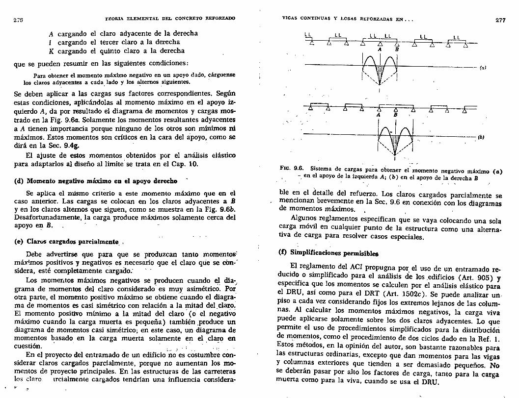
276 TEORIA ELEMENTAL DEL CONCRETO REFORZADO
A cargando el claro adyacente de la derecha I cargando el tercer claro a la derecha K cargando el quinto claro a la derecha
que se pueden resumir en las siguientes condiciones:
Para obtener el momento máximo negativo en un apoyo dado, cárguense los claros ad~acentes a cada. lado y los a}temos .siguientes.
Se deben aplicar a las cargas sus factores correspondientes. Según estas condiciones, aplicándolas al momento máximo en el apoyo izquierdo A, da por resultado el diagrama de momentos y cargas mostrado en la Fig. 9.6a. Solamente los momentos resultantes adyacentes a A tienen importancia porque ninguno de los otros son mínimos ni máximos. Estos momentos son críticos en la cara del apoyo, como se dirá en la Sec. 9.4g.
El ajuste de estos momentos obtenidos por el análisis elástico para adaptarlos al diseño al límite. se trata en el Cap. 10.
(d) Momento negativo máximo en el apoyo derecho
Se aplica el mismo criterio a este momento máximo que en el caso anterior. Las cargas se colocan en los claros adyacentes a B y en los claros alternos que siguen, como se muestra en la Fig. 9.6b. Desafortunadamente, la carga produce máximos solamente cerca del apoyo el? B.
(e) Claros cargados parcialmente, ,
Debe advertirse que para que se produzcan tanto momentos~ máximos positivos y negativos es necesario que el claro que se eón-· sidera, esté completamente cargado:
Los momer1tos máximos negativos se producen cuando el; día-_, grama de momentos del claro considerado· es muy asimétrico. Por_ otra parte, el momento positivo máximo se obtiene· éuando el diagrama de momentos es casi simétrico con relación a la mitad del_claro: El momento positivo mínimo a la mitad del claro · (o. el negativo máximo cuando la carga muerta es pequeña) también ,produce un diagrama de momentos casi simétrico; en este caso, un diagrama de momentos basado en la carga muerta solamente en el claro en cuestión. · · · , J _, •• •• • • • ,~ • •
En el proyecto del entramado de un edificio no es costumbre considerar claros cargados parcialmente, porque no aumentan los momentos de proyecto principales. En las estructuras de las carreteras los claro~ trcialmente cargados tendrían una influencia considera-
VIGAS CONTINUAS Y LOSAS REFORZADAS EN , , ,
' .
LL
=z-
,' '
Ll LL [; zs ¿
A B
P11
A B
1
LL LL
~E is-
---- (a,l
--------~~·~1 ~------(b}
!
277
F1c. 9.6. Sistema de cargas pa~a obtener et' momento negativo máximo (cz) -. en el apoyo de la izquierda A; ( b) en el apoyo de la derecha B
ble e1_1 el detalle del refuerzo. Los claros cargados parcialmente se menciOnan brevemente en la Sec. 9.6 en conexión con los diagramas de momentos máximos.
Algunos reglamentos especifican que se vaya colocando una sola carga móvil en cualquier punto de la estructura como una alternativa de carga para resolver casos especiales.
(f) Simplüicaciones permisibles
El reglamento del ACI propugna por el uso de un entramado reducid~. o simplificado para el análisis de los .edificios ( Art. 905) y especifica que los momentos se calculen por el análisis elástico para el DRU, así como para el DRT (Art. 1502c). Se puede analizar un, piso a cada vez considerando fijos los extremos lejanos de las columnas. Al calcular los momentos máximos negativos, la carga viva pued: aplicarse solamente sobre los dos claros adyacentes. Lo que penmte el uso de procedimientos simplificados para la distribución de ~amentos, como el procedimiento de dos ciclos dado en la Ref. 1. Estos métodos, en la opinión del autor, son bastante razonables para las estructuras ordinarias, excepto que dan momentos para las vigas Y columnas exteriores que tienden a ser demasiado pequeños. No se deberán pasar por alto los factores de carga, tanto para la carga muerta como para la viva, cuando se usa el DRU.
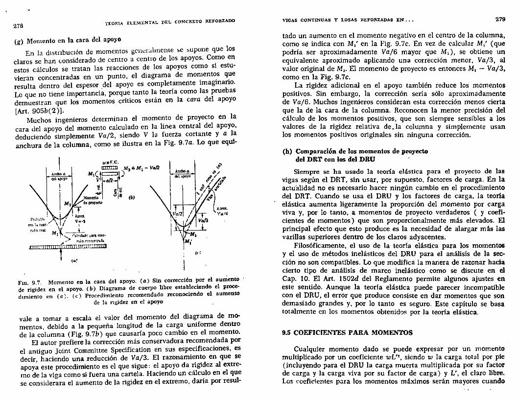
¡\
278 T:EORIA :ELEMENTAL DEL CONCRETO REFORZADO
(g) Momento en la cara del apoyo
En la dtstnbuctón de momentos gener:thnente !>e !>upone que los claros se han considerado de centro a centro de los apoyos. Co~o en estos cálculos se tratan las reacciones de los apoyos como si estuvieran concentradas en un punto, el diagrama de mo~1ent~s q~e resulta dentro del espesor _del apoyo es complet,amente 1magmano. Lo que no tiene importancia, porque tanto la teona como las pruebas demuestran que los momentos críticos están en la cara del apoyo [Art. 905b(2)].
Muchos ingenieros determinan el momento de proyecto en la cara del apoyo del momento calculado en la línea central del apoyo, deduciendo simplemente Va/2, siendo V la fuerza cortante Y a 1~ anchura de la columna, como se ilustra en la Fig. 9.7a. Lo que eqw-
wxF.C. IIII!I:Jl M 2 .:. M 1 - Va/2
Anebo tt M 1 (~.tc::::::Jj ) delapoyo r
. e f2 l M2 :o:~ ~~ (b)
. ,. i 1 Apla.
\ / V~·2 \( ' roóo real M ____ }_ 1 ! '":> •'r.lc~ ¡.ara rur-~ ,/ r1 úl- (":)'N"trtl'll.ih
~~l~!l~i'~IIT!IITIIIT!I~I~ll1~CTIVniTD~,~
..... {d
A ;>rOL
Vtt16
FIG. 9.7. Momento en la cara del apoyo. (a) Sin corrección por el aumento de rigidez en el apoyo. ( b) Diagrama de cuerpo libre estableciendo el proceduniento en (a). (e) Procedimiento recomendado reconociendo el aumento
de la ngidez en el apoyo
vale a tomar a escala el valor del momento del diagrama de momentos, debido a la pequeña longitud de la carga uniforme dentro de la columna (Fig. 9.7b) que causaría poco cambio en el momento.
El autor prefiere la corrección más conservadora recomendada por el antiguo Joint Committee Specification en sus especificaciones, es decir haciendo una reducción de Va/3. El razonamiento en que se apoy~ este procedimiento es el que sigue: el apoyo da rigidez al extremo de la viga como si fuera una cartela. Haciendo un cálculo en el que se considerara el aumento de la rigidez en el extremo, daría por resul-
VIGAS CONTINUAS Y LOSAS REFORZADAS EN ••• 279
tado un aumento en el momento negativo en el centro de la columna, como se indica con M/ en la Fig. 9.7c. En vez de calcular M/ (que podría ser aproximadamente Va/6 mayor que M1), se obtiene un equivalente aproximado aplicando una corrección menor, Va/3, al valor original de M1 • El momento de proyecto es entonces M1 - Va/3, como en la Fig. 9.7c.
La rigidez adicional en el apoyo también reduce los momentos positivos. Sin embargo, la corrección sería sólo aproximadamente de Vaj6. Muchos ingenieros consideran esta corrección menos cierta que la de la cara de la columna. Reconocen la menor precisión del cálculo de los momentos positivos, que son siempre sensibles a los valores de la rigidez relativa de .la columna y simplemente usan los momentos positivos originales sin ninguna corrección.
(h) Comparación de los momentos de proyecto del DRT con los del DRU
Siempre se ha usado la teoría elástica para el proyecto de las vigas según el DRT, sin usar, por supuesto, factores de carga. En la actu'alidad no es necesario hacer ningún cambio en el procedimiento del DRT. Cuando se usa el DRU y los factores de carga, la teoría elástica aumenta ligeramente la proporción del momento por carga viva y, por lo tanto, a momentos de proyecto verdaderos ( y coeficientes de momentos) que son proporcionalmente más elevados. El principal efecto que esto produce es la necesidad de alargar más las varillas superiores dentro de los claros adyacentes.
Filosóficamente, el uso de la teoría elástica para los momentos y el uso de métodos inelásticos del DRU para el análisis de la sección no son compatibles. Lo que modifica la manera de razonar hacia cierto tipo de análisis de marco inelástico como se discute en el Cap. 10. El Art. 1502d del Reglamento permite algunos ajustes en este sentido. Aunque la teoría elástica puede parecer incompatible con el DRU, el error que produce consiste en dar momentos que son demasiado grandes y, por lo tanto es seguro. Este capítulo se basa totalmente en los momentos obtenidos por la teoría elástica.
9.5 COEFICIENTES PARA MOMENTOS
Cualquier momento dado se puede expresar por un momento multiplicado por un coeficiente wL'2
, siendo w la carga total por pie (incluyendo para el DRU la carga muerta multiplicada por su factor de carga y la carga viva por su factor de carga) y L', el claro libre. Los coeficientes para los momentos máximos serán mayores cuando
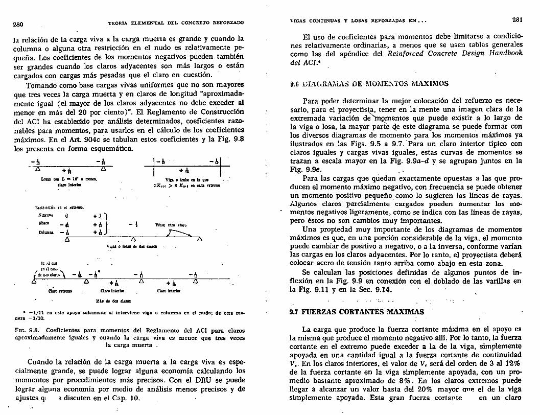
280 TEORIA ELEMENTAL DEL CONCRETO REFORZADO
la relación de la carga viva a la carga muerta es grande y cuando la columna o alguna otra restricción en el nudo es relativamente pequeña. Los coeficientes de los momentos negativos pueden también ser grandes cuando los claros adyacentes son más largos o están cargados con cargas más pesadas que el claro en cuestión. · _
Tomando como base cargas vivas uniformes que no son mayores que tres veces la carga muerta y en claros de longitud "aproximadamente igual (el mayor de los claros adyacentes no debe exceder al menor en más del 20 por ciento)". El Reglamento de Construcción del ACI ha establecido por análisis determinados, coeficientes razonables para momentos, para usarlos en el cálculo de los coeficientes máximos. En el Art. 904c se tabulan estos coeficientes y la Fig. 9.8 los presenta en forma esquemática.
-ls -ll zs +t. zs
Losas to~~ L = 10' o menos, claro ll!ierW
&estmd6n en el enr-,
Nliii'U'" o + ,\1 Abato -t. +le J Columna -t. +¡\
15.
+t. Vlp o trabe e11 la que
IK,ol > 8 Kont e11 rada ntrtme
V b.'lt otro tlaru
zs \'¡¡;u o losas de dus danll
1& .>.1 que
1 en el as..
l de wt claru. \
. Claromnmo
2S l +a. Claro IDUrtor
M b de dos claras
-h -fi +/¡ zs
Claro lnúrtor
• -1/11 en este apoyo solamente si interviene viga o columna en el nudo; de otra ma. nera -1/10.
Fxc. 9,8. Coeficientes para momentos del Reglamento del ACI para claros aproximadamente iguales y cuando la carga viva es menor que tres veces
la carga muerta _
Cuando la relación de la carga muerta a la carga viva es especialmente grande, se puede lograr alguna economía calculando los momentos por procedimientos más precisos. Con el DRU se puede lograr alguna economía por medio de análisis menos precisos y de ajustes q1 ~discuten en el Cap. 10.
VIGAS CONTINUAS Y LOSAS REFORZADAS EN , , , 281
El uso de coeficientes para momentos debe limitarse a condiciones relativamente ordinarias, a menos que se usen tablas generales como las del apéndice del Reinforced Concrete Design Handbook del ACI.•
Para poder determinar la mejor colocación del refuerzo es necesario, para el proyectistf., tener en la mente una imagen clara de la extremada variación de 'l-nementos que puede existir a lo largo de la viga o losa, la mayor parte Q.e este diagrama se puede formar con los diversos diagramas de momento para los momentos máximos ya ilustrados en las Figs. 9.5 a 9.7. 'Para un claro interior típico con claros iguales y cargas vivas iguales, estas curvas de momentos se trazan a escala mayor en la Fig. 9.9a-d y se agrupan juntos en la Fig. 9.9e. _
Para las cargas que qúedan exactamente opuestas a las que producen el momento máximo negativo, con frecuencia se puede obtener un momento positivo pequeño_ como lo sugieren las lineas de rayas. iJgunos claros parcialmente cargados pueden aumentar los momentos negativos ligeramente, como se indica con las líneas de rayas, pero éstos no son cambios muy importantes.
Una propiedad muy importante de los diagramas de momentos máximos es que, en una porción considerable de la viga, el momento puede cambiar de positivo a negativo, o a la inversa, conforme varían las cargas en los claros adyacentes. Por lo tanto, el proyectista deberá colocar acero de tensión tanto arriba como abajo en esta zona.
Se calculan las posiciones definidas de algunos puntos de inflexión en la Fig. 9.9 en conexión con el doblado de las varillas en la Fig. 9.11 y en la Sec. 9.14.
9.7 FUERZAS CORTJ\1\'TES MAXIMAS
La carga que produce la fuerza cortante máxima en el apoyo es la misma que produce el momento negativo alli. Por lo tanto, la fuerza cortante en el extremo puede exceder a la de la viga, simplemente apoyada en una cantidad igual a la fuerza cortante de continuidad Ve. En los claros interiores, el valor dé V., será del orden de 3 al 12% de la fuerza cortante en la viga simplemente apoyada, con un promedio bastante aproximado de 8%. En los claros extremos puede llegar a alcanzar un valor hasta del 20% mayor one el de la viga simplemente apoyada. Esta gran fuerza cortapte en un , claro
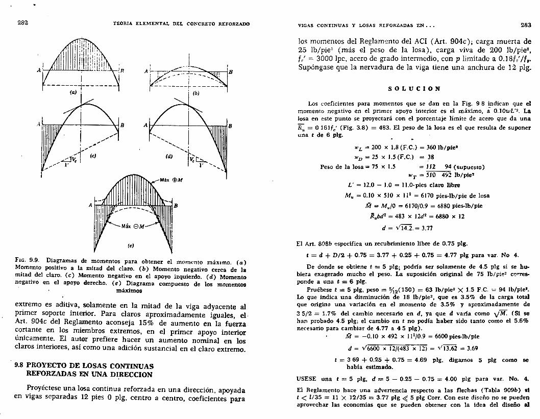
282 TEORIA ELEMENTAL DEL CONCRETO REFORZADO
' ' 1 _¡
A~~-~-S- :----, ' t -, -----t- -----~
(b)
Mtlx @M
Máx 8M
(el
FIG. 9.9. Diagramas de momentos para obtener el momento máx1mo. {a) Momento positivo a la mitad del claro. (b) Momento negativo cerca de }a mitad del claro. (e) Momento negativo en t:l apoyo izquierdo. (d) Momento negativo en el apoyo derecho. (e) Diagrama compuesto de los momentos
máximos
ex~emo es aditiva, solamente en la mitad de la viga adyacente al pnmer soporte interior. Para claros aproximadamente iguales, el, Art. 904c del Reglamento aconseja 15% de aumento en la fuerza ~o~ante en los miembros extremos, en el primer apoyo interior urucamente. El autor prefiere hacer un aumento nominal en los claros interiores, así como una adición sustancial en el claro extremo.
9.8 PROYECTO DE LOSAS CONTINUAS REFORZADAS EN UNA DIRECCION
'
~royéctese una losa continua reforzada en una dirección, apoyada en VIgas separadas 12 pies O plg, centro a centro, coeficientes para
VIGAS CONTINUAS Y LOSAS REFORZADAS EN , . , 283
los momentos del Reglamento del ACI (Art. 904c); carga muerta de 25 lb/pie~ (más el peso de la losa), carga viva de 200 lb/pie2 ,
fr' = 3000 lpc, acero de grado intermedio, con p limitado a 0.18f / /f11•
Supóngase que la nervadura de la viga tiene una anchura de 1:2 plg.
SOLUCION
Los coeficientes para momentos que se dan en la Fig. 9 8 indican que el momento negativo en el pnmer apoyo interior es el máximo, a 0.10u,L'2 • La losa en este punto se proyectará con el porcentaje límite de acero que da una
R,. = O 16lfc' (Fig. 3.8) = 483. El peso de lá losa es el que resulta de suponer una t de 6 plg.
"'L = 200 X 1.8 (F.C.) = 360 lb/pie'
WJ) = 25 X 1.5 (F.C.) = ~8 Peso de la losa= 75 x 1.5 = 112 94 (supuesto)
WT = 5J0 492 lb/pie2
L' = 12.0 - 1.0 = 11.0-pies claro libre
M,. = 0.10 x 510 x 11 2 = 6170 pies-lb/pie de losa
!VI= Mu/0 = 6170/0.9 = 6880 pies-lb/pie
Rubd2 = 483 X 12d2 = 6880 X 12
d = ,/14.2. = 3.77
El Art. 808b ~specüica un recubrimiento libre de 0.75 plg.
t = d + D/2 + 0.75 = 3.77 + 0.25 + 0.75 = 4.77 plg para var. No 4.
De donde se obtiene t = 5 plg; podrla ser solamente de 4.5 plg si se hubiera exagerado mucho el peso. La suposición original de 75 lb/¡:ie2 ct::~rres
ponde a una t = 6 plg. Pruébese t = 5 plg, peso = ~2(150) = 63 lb/pie2 X 1.5 F.C. = 94 lb/pie1•
Lo que indica una disminución de lB lb/pie2 , que es 3.5% de la carga total que origina una variación en el momento de 3.5% y aproximadamente de
3 5/2 = 1.7% del cambio necesario en d, ya que d varia como y M. (Si se han probado 4.5 plg; el cambio en t no pod[a haber sido tanto como el 5.6% necesario para cambiar de 4.77 a 4 5 plg).
!VI = -0.10 x 492 x 11 2/0.9 = 6600 pies-lb/pie
d = V6600 X 12/(483 X 12) = \1 13.62 = 3.69
t = 3 69 + 0.2.5 + 0.75 = 4.69 plg, digamos 5 plg como se babia estimado.
USESE una t = 5 plg, d = 5 - 0.25 - 0.75 = 4.00 plg para var. No. 4.
El Reglamento hace una advertencia respecto a las flechas (Tabla 909&) si t < l/35 = ll X 12/35 = 3.77 plg ~ 5 plg Corr. Con este diseño no se pueden aprovechar las economias que se pueden obtener con la idea del diseño al
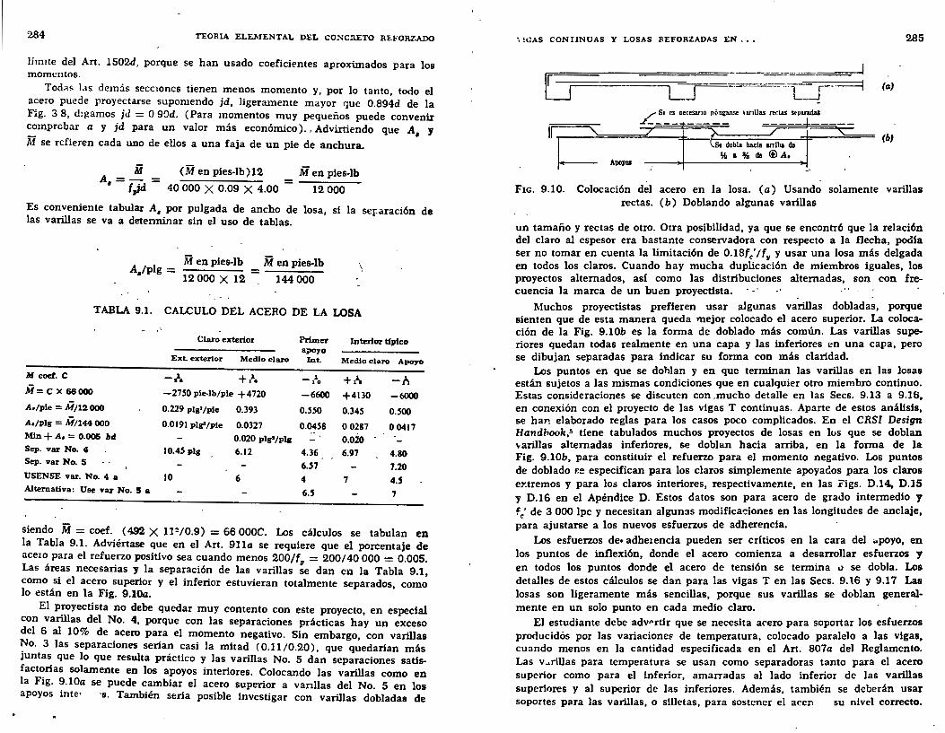
284 TEORIA ELEMENTAL DEL CO!-IC!\ETO REFORZADO
límite del Art. 1502d, porque se han usado coeficientes aproximados para los momentos.
Todils las dcm:ís secc10nes tienen menos momento y, por lo tanto, todo el acero puede proyectarse supomendo jd, ligeramente mayor que 0.894d de la Fig. 3 8, d:gamos jd = O 90d. (Para momentos muy pequeños puede convenir ~mprcbar a Y jd para un valor m:ís económico). , Advirtiendo que A, y
M se refieren cada uno de ellos a una faja de un pie de anchura.
M A=-=
• fJd
(M en píes-lb)12
40 000 X 0.09 X 4.00
M en pies-lb ------
12 000
Es conveniente tabular A, por pulgada de ancho de losa, si la se¡:aración de las varillas se va a determinar sin el uso de tablas.
1 M en píes-lb M en pies-lb
A /p g = = ' 12 000 X 12 144 000
\
TABLA 9.1. CALCULO DEL ACERO DE LA LOSA
Claro exterior Primer Interior típico apoyo
ExL exterior Medio claro In t. Medio claro Apoyo
M coef. e -l. +,J.. -lo +.\ -f. M= ex 66000 -2750 pie-lb/pie +4720 -6600 +4130 -6000 A./pie = M/12 000 0.229 plg'/ple 0.393 0.550 0.345 0.500 A./plg = M/144 000 0.0191 plg'/pie 0.0327 0.0458 o 0287 00417 Min + A, = 0.005 bd 0.020 plg2/plg 0.020 Sep. var No. 4 10.45 plg 6.12 4.36 6.97 4.80 Sep. var No. S 6.57 7.20 USENSE var. No. 4 a 10 6 4 7 4.5 Alternativa: Use var No. 5 a 6.5 7
siendo M= coef. (4.92 X 1P/0.9) = 66 OOOC. Los cálculos se tabulan en la Tabla 9.1. Adviértase que en el Art. 9lla se requiere que el porcentaje de ace1o para el refue.rzo positivo sea cuando menos 200/fu = 200/40 000 = 0.005. Las áreas necesanas y la separación de las varillas se dan en la Tabla 9.1, como .si el acero superior y el inferior estuvieran totalmente separados, como lo estan en la Fig. 9.104.
El p~oyectista no debe quedar muy contento con este proyecto, en especial con varillas del No. 4, porque con las separaciones prácticas hay un exceso del 6 al 10% de acero para el momento negativo. Sin embargo, con varillas ~o. 3 las separaciones serian casi la mitad ( 0.11/0.20), que quedarían más JUntas que lo que resulta práctico y las varillas No. 5 dan separaciones satisfactorias solamente en Jos apoyos interiores. Colocando las varillas como en la Fig. 9.10a se puede cambiar el acero superior a vanllas del No. 5 en los apoyos inte• ·s. También sería posible investigar con varillas dobladas de
•, !GAS CONflNUAS Y LOSAS REFORZADAS EN ••• 285
LJ L L__j (a)
~(b} 11
1~ APCI)'OS
F1c. 9.10. Colocación del acero en la losa. (a) Usando solamente varillas rectas. ( b) Doblando algunas varillas
un tamaño y rectas de otro. Otra posibilidad, ya que se encontró que la relación del claro al espesor era bastante conservadora con respecto a la flecha, pocUa ser no tomar en cuenta la limitación de 0.18fc'lf11 y usar una losa más delgada en todos los claros. Cuando hay mucha duplicación de miembros iguales, los proyectos alternados, asi como las distribuciones alternadas, son con frecuencia la marca de un buen proyectista.
Muchos proyectistas prefieren usar algunas varillas dobladas, porque sienten que de esta manera queda mejor colocado el acero superior. La colocación de la Fig. 9.10b es la forma de doblado más común. Las varillas superiores quedan todas realmente en una capa y las inferiores en una capa, pero se dibujan separadas para indicar su forma con más claridad.
Los puntos en que se dohlan y en que terminan las varillas en las losas está., sujetos a las mismas condiciones que en cualquier otro miembro continuo. Estas consideraciones se discuten con .mucho detalle en las Secs. 9.13 a 9.16, en conexión con el proyecto de las vigas T continuas. Aparte de estos análisis, se han elaborado reglas para los casos poco complicados. En el CRSI Design Handbook,5 tiene tabulados muchos proyectos de losas en los que se doblan \oarillas alternadas inferiores, se doblan hacia arriba, en la forma de la Fig. 9.10b, para constituir el refuerzo para el momento negativo. Los puntos de doblado r.e especifican para los claros simplemente apoyados para los claros e:r.tremos y para los claros interiores, respectivamente, en las i'ígs. D.14., D.15 y D.16 en el Apéndice D. Estos datos son para acero de grado intermedio y fe' de 3 000 lpc y necesitan algunas modificaciones en las longitudes de anclaje, para ajustarse a los nuevos esfuerzos de adherencia.
Los esfuerzos de• adhe1encia pueden ser críticos en la cara del :.poyo, en los puntos de inflexión, donde el acero comienza a desarrollar esfuerzos y en todos los puntos donde el acero de tensión se termina .., se dobla. Los detalles de estos cálculos se dan para las vigas T en las Secs. 9.1.6 y 9.17 Las losas son ligeramente más sencillas, porque sus varillas se doblan generalmente en un solo punto en cada medio claro.
El estudiante debe adv"'rtir que se necesita acero para soportar los esfuerzos producidós por las variacioneF de temperatura, colocado paralelo a las vigas, cuando menos en la cantidad especificada en el Art. 807a del Reglamento. Las v ... rillas para temperatura se usan como separadoras tanto para el acero superior como para el inferior, amarradas al lado inferior de las varillas superiores y al superior de las inferiores. Además, también se deberán usar soportes para las varillas, o silletas, para sostener el acei'\ su nivel correcto.
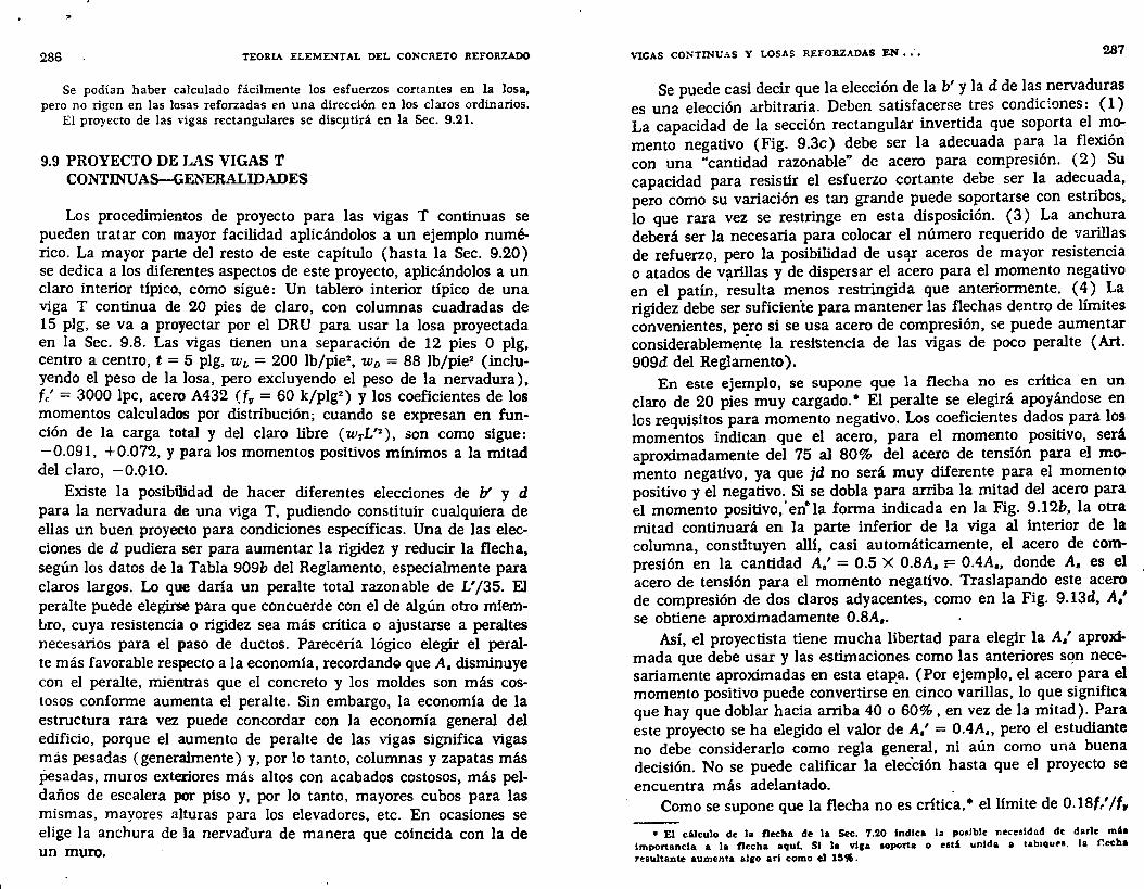
"
286 TEORIA ELEMENTAL DEL CONCRETO REFORZADO
Se podían haber calculado fácilmente los esfuerzos cortantes en la Josa, pero no rigen en las losas reforzadas en una dirección en los claros ordinarios.
El pro)'ecto de las vigas rectangulares se discptirá en la Sec. 9.21.
9.9 PROYECTO DE LAS VIGAS T CONTINUAS-GENERALIDADES
Los procedimientos de proyecto para las vigas T continuas se pueden tratar con mayor facilidad aplicándolos a un ejemplo numérico. La mayor parte del resto de este capítulo (hasta la Sec. 9.20) se dedica a los diferentes aspectos de este proyecto, aplicándolos a un claro interior típico, como sigue: Un tablero interior típico de una viga T continua de 20 pies de claro, con columnas cuadradas de 15 plg, se va a proyectar por el DRU para usar la losa proyectada en la Sec. 9.8. Las vigas tienen una separación de 12 pies O plg, centro a centro, t = 5 plg, wL = 200 lb/pie2 , w 0 = 88 lb/pie2 (incluyendo el peso de la losa, pero excluyendo el peso de la nervadura), fe' = 3000 lpc, acero A432 (f11 = 60 k/plg2
) y los coeficientes de los momentos calculados por distribución; cuando se expresan en función de la carga total y del claro libre ( wTL'2 ), son como sigue: -0.091, + 0.072, y para Jos momentos positivos mínimos a la mitad del claro, -0.010.
Existe la posibilidad de hacer diferentes elecciones de b' y d para la nervadura de una viga T, pudiendo constituir cualquiera de ellas un buen proyecto para condiciones específicas. Una de las elecciones de d pudiera ser para aumentar la rigidez y reducir la flecha, según los datos de la Tabla 909b del Reglamento, especialmente para claros largos. Lo que daría un peralte total razonable de L' /35. EJ peralte puede elegirse para que concuerde con el de algún otro miemLro, cuya resistencia o rigidez sea más crítica o ajustarse a peraltes necesarios para el paso de duetos. Parecería lógico elegir el peralte más favorable respecto a la economía, recordandg que A, disminuye con el peralte, mientras que el concreto y los moldes son más costosos conforme aumenta el peralte. Sin embargo, la economía de la estructura rara vez puede concordar con la economía general del edificio, porque el aumento de peralte de las vigas significa vigas más pesadas (generalmente) y, por lo tanto, columnas y zapatas más pesadas, muros exteriores más altos con acabados costosos, más peldaños de escalera por piso y, por lo tanto, mayores cubos para las mismas, mayores alturas para los elevadores, etc. En ocasiones se elige la anchura de la nervadura de manera que coincida con la de un muro.
VIGAS COJ:-;TINUAS Y LOSAS REFORZADAS EN •• -. 287-
Se puede casi decir que la elección de la b' y la d de las nervaduras es una elección arbitraria. Deben satisfacerse tres condic~ones: ( 1) La capacidad de la sección rectangular invertida que soporta el momento negativo (Fig. 9.3c) debe ser la adecuada para la flexión con una "cantidad razonable" de acero para compresión. (2) Su capacidad para resistir el esfuerzo cortante debe ser la adecuada, pero como su variación es tan grande puede soportarse con estribos, lo que rara vez se restringe en esta disposición. (3) La anchura deberá ser la necesaria para colocar el número requerido de varillas de refuerzo, pero la posibilidad de us~ aceros de mayor resistencia o atados de v~rillas y de dispersar el acero para el momento negativo en el patín, resulta menos restringida que anteriormente. ( 4) La rigidez debe ser suficien'te para mantener las flechas dentro de límites convenientes, pero si se usa acero de compresión, se puede aumentar considerablemente la resiStencia de las vigas de poco peralte (Art. 909d del Reglamento).
En este ejemplo, se supone que la flecha no es critica en un claro de 20 pies muy cargado. • El peralte se elegirá apoyándose en los requisitos para momento negativo. Los coeficientes dados para los momentos indican que el acero, para el momento positivo, será aproximadamente del 75 al 80% del acero de tensión para el momento negativo, ya que jd no será muy diferente para el momento positivo y el negativo. Si se dobla para arriba la mitad del acero para el momento positivo,' ene la forma indicada en la Fig. 9.12b, la otra mitad continuará en la parte inferior de la viga al interior de la columna, constituyen allí, casi automáticamente, el acero de compresión en la cantidad A.' = 0.5 X 0.8A, r= 0.4A,, donde A. es el acero de tensión para el momento negativo. Traslapando este acero de compresión de dos claros adyacentes, como en la Fig. 9.13d, A,' se obtiene aproximadamente 0.8A,.
Así, el proyectista tiene mucha libertad para elegir la A,' aproximada que debe usar y las estimaciones como las anteriores sqn necesariamente aproximadas en esta etap_a. (Por ejemplo, el acero para el momento positivo puede convertirse en cinco varillas, lo que significa que hay que doblar hacia arriba 40 o 60%, en vez de la mitad). Para este proyecto se ha elegido el valor de A.' = 0.4A., pero el estudiante no debe considerarlo como regla general, ni aún como una buena decisión. No se puede calificar la elección hasta que el proyecto se encuentra más adelantado. .
Como se supone que la flecha no es crítica,• el límite de 0.18(//f,
• El c6lculo de la flecha de la Sec. 7.20 Indica la poaible necesidad de darle mb importancia a la flecha aquf. SI la viga soporta o e&t' unida a 1abaqure. la r.ccha 7esultante aumenta al1o arl como el 15~.
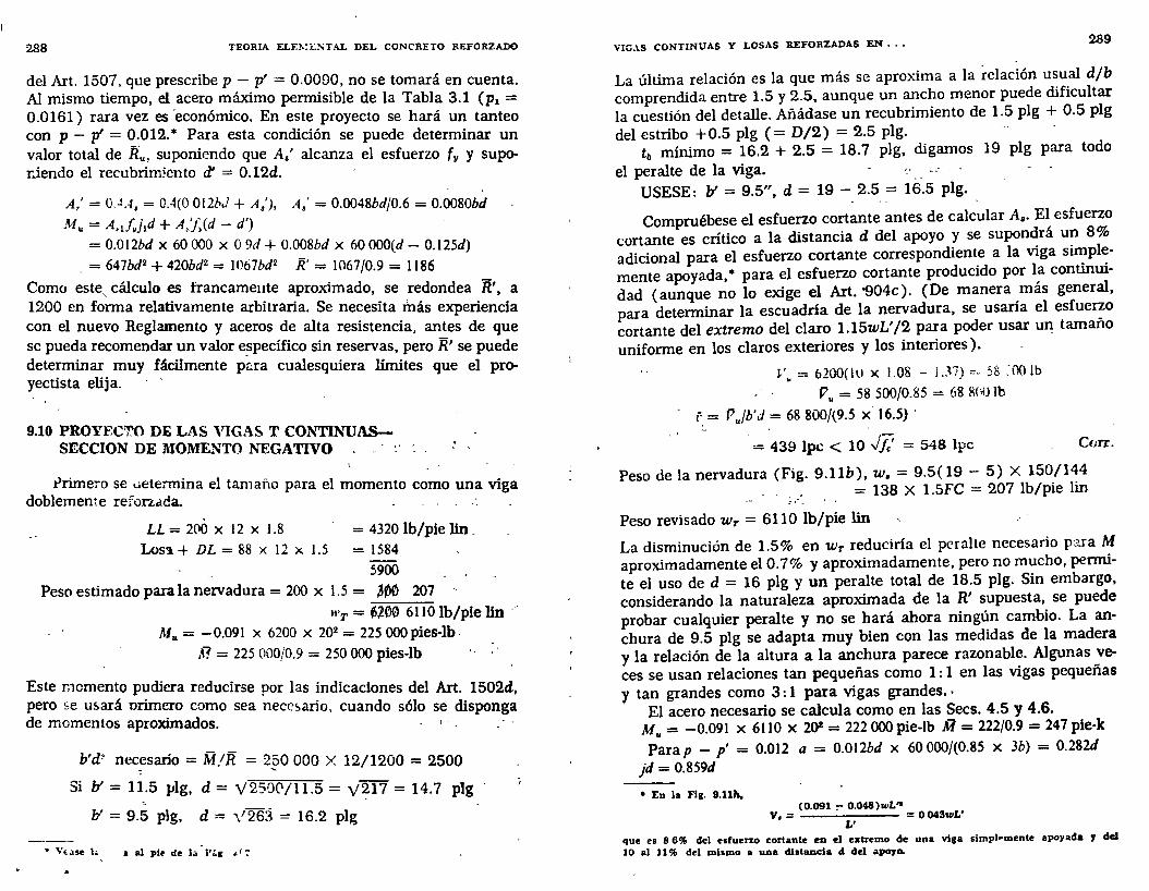
288 TEORIA ELE!\!<:::.;TA.L DEL CONCRETO REFORZADO
del Art. 1507, que prescribe p- p' = 0.0090, no se tomará en cuenta. Al mismo tiempo, el acero máximo permisible de la Tabla 3.1 (pl = 0.0161) rara vez es 'económico. En este proyecto se hará un tanteo con p - p' = 0.012. • Para esta condición se puede determinar un valor total de R .. , suponiendo que As' alcanza el esfuerzo (11 y suporiendo el recubrimiento ~ = 0.12d.
A; = O . .!A, = 0.4(0 012b,í + A/), A.' = 0.0048bdf0.6 = 0.0080bd
M,. = A,J11jld + A,'j~(d - d')
= 0.012bd X 60 000 X O 9d + 0.008bd X 60 OOO(d- 0.125d)
= 647bd2 + 420bd2 = W67bd 2 R' = 1067/0.9 = 1186
Como este, cálculo es francameute aproximado, se redondea R'. a 1200 en forma relativamente arbitraria. Se necesita inás experiencia con el nuevo Reglamento y aceros de alta resistencia, antes de que se pueda recomendar un valor e_specífico sin reservas, pero R' se puede determinar muy fácilmente p~ra cualesquiera límites que el proyectista elija.
9.10 PROYECTO DE LAS VIGA~ T COI\TTINUASSECCION DE MOMENTO NEGATIVO
.t>rimero se ..aetennina el tamaño para el momento como una viga doblemente refonada. - _ ..
LL = 200 X 12 X 1.8 = 4320 lb/pie lin _ Los1. + DL = 88 X 12 X 1.5 = 1584
5900
Peso estimado para la nervadura= 200 x 1.5 = ~00 207
WT = ~~00 6110 lb/pie lin .M,.= -0.091 X 6200 X 202 = 225 OOOpies-lb ·
A? = 225 000/0.9 = 250 000 pies-lb
Este memento pudiera reducirse por las indicaciones del Art. 1502d, pero se u5.ará orimero como sea nece~ario, cuando sólo se disponga de momentos aproximados. ' -
b'd~ necesario = M/R = 2§0 000 X 12/1200 = 2500
Si b' = 11.5 }Jlg, d = \12500/11.5 = y~17 = 14.7 plg --
b' = 9.5 p1g, d = \1 263 = 16.2 plg
• v~ase h & al plr de la "r:.g ~' 7
VIG.\S CONTINUAS Y LOSAS REFORZADAS EN · .• 289
La última relación es la que más se aproxima a la relación usual d/b comprendida entre 1.5 y 2.5. aunque un ancho menor puede dificultar la cuestión del detalle. Añádase un recubrimiento de 1.5 plg + 0.5 plg del estribo +0.5 plg ( = D/2) = 2.5 plg. -
tb mínimo = 16.2 + 2.5 = 18.7 plg. digamos 19 plg para todo el peralte de la viga. __ --
USESE: b' = 9.5", d = 19 - 2.5 = 16.5 plg.
Compruébese el esfuerzo cortante antes de calcular A,. El esfuerzo cortante es crítico a la distancia d del apoyo y se supondrá un 8% adicional para el esfuerzo cortante correspondiente a la viga sin_lpl~mente apoyada, • para el esfuerzo cortante producido por 1~ continUIdad (aunque no lo exige el Art. '904c). (De manera ,mas general, para determinar la escuadría de la nervadura, se usana el esfue~o cortante del extremo del claro 1.15wL'/2 para poder usar un tamano uniforme en los claros exteriores y los interiores).
V~ = 6200(ltJ x 1.08 - J.37) =- 58 :00 lb
V .. = 58 500/0.85 = 68 l\('ll lb
r. = P .. /b'J = 68 800/(9.5 x 16.5) ·
= 439 lpc < 10 J¡: = 548 lpc Cürr.
Peso de la nervadura (Fig. 9.llb), w. = 9.5( 19 - 5) X 150/144 __ ; ,.-_ = 138 X 1.5FC = 207 lb/pie lin
Peso revisado Wr = 6110 lb/pie lin
La disminución de 1.5% en Wr reduciría el peralte necesario p:J.ra M aproximadamente el 0.7% y aproximadamente, pero no mucho, permite el uso de d = 16 plg y un peralte total de 18.5 plg. Sin embargo, considerando la naturaleza aproximada de la R' supuesta, se puede probar cualquier peralte y no se hará ahora ningún cambio. La anchura de 9.5 plg se adapta muy bien con las medidas de la madera y la relación de la altura a la anchura parece razonable. Algunas veces se usan relaciones tan pequeñas como 1 : 1 en las vigas pequeñas y tan grandes como 3: 1 para vigas grandes. · - El acero necesario se calcula como en las Secs. 4.5 y 4.6.
M u= -0.091 x 6110 x 2()2 = 222 000 pie-lb ~ = 222/0.9 = 247 pie-k Parap - p' = 0.012 a = 0.012bd x 60 000/(0.85 x 3b) = 0.282d
jd = 0.859d
• En la Fig. 9.11h. (0.091 ~ 0.048)wL"
Ve= =O 043wL' L'
que ea 8 6% del esfuerzo cortante en d extremo de una viga slmph•mente apoyada J dd 10 al 11% del mismo a una diataucla d del 81'070.

1\
290 TEORIA ELEMENTAL DEL CONCRETO REFORZADO
ft?l = (0.012 X 9.5 X 16~5)60 000(0.859 X 16.5)/12 000 = 133.3 k-pie Ji71 = M- ft71 = 247- 133.3 = 113.7 k-pie
133 3 X 12 A,1 =
60 O
859 = 1.88plg2 (0 plbd= 0.012 X 9.5 X 16.5 = 1.88)
X . X 16.5
113.7 X 12 = 1.62 l 2
60(16.5- 2.5) p g
A, total negativa = 3.50 p1g2
e= a/0.85 = 0.282 X 16.5/0.85 = 5.47 plg f.; = 0.003(5.47- 2.5)/5.47= 0.00163. J.:= _29 X 103
X 0.00163 = 47._3 k/plg2)
A.'= 113.7 X 12 = 2 . 2~ l 2
(47.3 - 0.85 X 3)(16.5 - 2.5) p g
Debido a f.' ~{11• esta A,' es considerablemente mayor que 0.4A,. que originalmente se había elegido como objetivo. Un examen del cálculo de R' indica que un f.' inferior en el segundo término del cálculo de M,. reduciría R' entre 100 y 150 unidades. Una revisión de las dimensiones de la viga puede hacerse con esta intensión, pero no sería difícil completar esta área tan grande A,'. Por lo tanto, no se revisará.
9.11 PROYECTO DE LAS VIGAS T COJ'PfiNUASpARA EL MOMENTO POSITIVO
- .
El peralte total de 19 plg ya elegido para el momento negativo fija el peralte efectivo a la mitad del claro. Para una capa de acero. (Fig. 9.11d).
~positiva = 19 plg - .1.5 plg recubrinúento - 0.5 plg estribo - 0.5 plg (para D/2) = 16.5 plg_
jd de tanteo = 16.5 - t/2 = 14.0 plg, o 0.9d = 14.85 plg. Usesc un valor mayor.
M = +0.072 X 6110 X 202 = 176 000 pies-lb
R ~ 176 000/0 o= 195 500pies-lb
A d tanteo = Al = 195 500 X 12 = 2 plg• • e J,jd 60 000 X 14.85 ·64
VIGAS CONTINUAS Y LOSAS REFORZADAS EN •••
r2 !:1-
~-OUO o
L :r165.
---..19.5. 1-(aJ
b = L/4 = 60'"-USE b = b'+ 16t = 115+80 =91.5• b = sep ,~gu = 144.
. ~u·=- + Gd= 1662"'
_l
(p)
(h} (i}
¡-f +-f ~OD1wJ.•0
00192wL·'gi:~l:' (jJ
2.91
Ir)
Fic. 9.11. Croquis de proyecto para las vtgas,T continuas. (a) Peralte su· puesto para el momento negativo. (b) Peso estimado, área sombreada. (e) Triángulo de deformaciones para el cálculo de f,'. (d) Peralte supuesto para el momento positivo. (e) Posición del P l. con momento máximo positivo M. ( f) Altura actual al acero superior según se elija. (g) Peralte actual al acero inferior como se eliJa. (h) Situación .. exacta .. del P.l. con momento negativo máximo M. (i) Situación aproximada del P.l. con momento negativo máximo
M. (j) Momento positivo mfnimo cerca de la mitad del claro
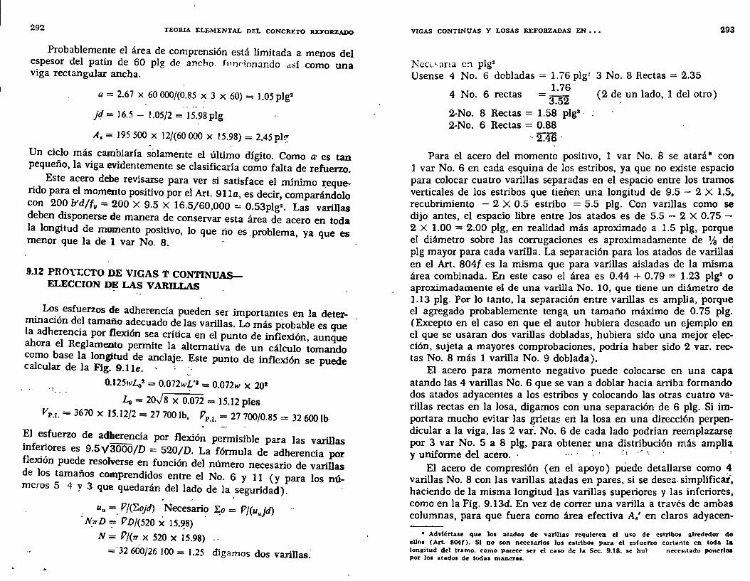
292 TEORIA ELEMENTAL DEL CONCRETO REFORZADO
Probablemente el área de comprensión está limitada a menos del espesor del patín de 60 plg de ancho. ftulrionando dSÍ corno una viga rectangdlar ancha.
a = 2.67 X 60 000/(0.85 ~ 3 X 60) = 1.05 plg2
N= 16.5- !.05/2 = 15.98plg
A,= 195 500 X 12/(60000 X 15.98) = 2.45pl~ .. .
Un ciclo más cambiaría sólamente el último dígito. Corno a• es tan pequeño, la viga evidentemente se clasificaría como falta de refuerzo. . Este acero debe revisarse para ver si satisface el mínimo :r:eque
ndo para el momento positivo por el Art. 911a, es decir, comparándolo con 200 b'd/f11 = 200 X 9.5 X 16.5/60,000 = 0.53plg2 • Las varillas deben disponerse de manera de conservar esta área de acero en toda la longitud de momento positivo, lo que ño es .problema, ya que es menor que la de 1 var No. 8. -
9.12 PROYECTO DE VIGAS T CONTINUASELECCION ~~ LAS VARILLAS
. Lo~, esfuerzos de adherencia pueden ser importantes en la determmacwn d~l tamaño adecuado de las varillas. Lo más probable es que la adherencia por flexión sea crítica en el punto de inflexión, aunque ahora el Reglamento permite la alternativa de un cálculo tomando como base la longitud de anclaje. Este punto de inflexión se puede calcular de la Fig. 9.lle. --
0.125wL02 = 0.012w~'2 = 0.072w x 201
Lo= 20Js x 0.072 = 15.12 pies vP.r. = 3670 x 15.12/2 = 21100 lb, PP.I. = 21700/0.85 = 32 600 lb
El esfuerzo de adherencia por flexión permisible para las varillas infe~ores es 9.5y3000/D = 520/D. La fórmula de adherencia por flexwn puede resolverse en función del número necesario de varillas de los tamaños comprendidos entre el No. 6 y 11 (y para los números 5 4 y 3 que quedarán. del la~o de la .seguridad).
uu =. Pj('f..ojd) Necesario ~o= Pf(uujd) NrrD =;= PD/(520 X 15.~8) .
N= Pj(1T X 520 X 15.98)
=·32 600/26 100 = 1.25 digamos dos varillas:
VIGAS CONTINUAS Y LOSAS REFORZADAS EN , , •
Nccv,ana c:1 pJgz Usense 4 No. 6 dobladas = 1.76 plg" 3 No. 8 Rectas = 2.35
1.76 4 No. 6 rectas -3.52 2-No. 8 Rectas = 1.58 plg11 •
2-No. 6 Rectas = 0.88 ·, 2.46.
(2 de un lado, 1 del otro)
293
Para el acero del momento positivo, 1 var No. 8 se atará • con 1 var No. 6 en cada esquina de los estribos, ya que no existe espacio para colocar cuatro varillas separadas en el espacio entre los tramos verticales de los estribos que tienen una longitud de 9.5 - 2 X 1.5, recubrimiento - 2 X 0.5 estribo = 5.5 plg. Con varillas corno se dijo antes, el espacio libre entre los atados es de 5.5 - 2 X O. 75 -2 X 1.00 = 2.00 plg, en realidad más aproximado a 1.5 plg, porque el diámetro sobre las corrugaciones es aproximadamente de % de plg mayor para cada varilla. La separación para los atados de varillas en el Art. 804f es la misma que para varillas aisladas de la misma área combinada. En este caso el área es 0.44 + O. 79 = 1.23 pJgz o aproximadamente el de una varilla No. 10, que tiene un diám~tro de 1.13 plg. Por lo tanto, la separación entre varillas es amplia, porque el agregado probablemente teng~ un tamaño máximo de O. 75 plg. (Excepto en el caso en que el autor hubiera deseado un ejemplo en el que se usaran dos varillas dobladas, hubiera sido una mejor elección, sujeta a mayores comprobaciones, podría haber sido 2 var. rectas No. 8 más 1 varilla No. 9 doblada).
El acero para momento negativo puede colocarse en una capa atando las 4 varillas No. 6 que se van a doblar hacia arriba formando dos atados adyacentes a los estribos y colocando las otras cuatro varillas rectas en la losa, digamos con una separación de 6 plg. Si importara mucho evitar las grietas erl la losa en una dirección perpendicular a la viga, las 2 vai. No. 6 de cada lado podrían reemplazars~ por 3 var No. 5 a 8 plg, para obtener una distribución más amplia y uniforme del acero. · · ··' · ' '- · '
El acero de compresión (en el apoyo) puede detallarse como ~ varillas No. 8 con las varillas atadas en pares, si se desea. simplificar~ haciendo de la misma longitud las varillas superiores y las inferiores, como en la Fig. 9.13d. En vez de correr una varilla a través de ambas columnas, para que fuera como área efectiva A.' en claros adyacen-
• Adviértase que loa atados de varillas requieren el uso de estribos alrededor de eUns ( Art. 804(). SI no son necesarios los estribos para el esfuerzo cortante en toda la longitud del tramo, <"omo parecr ser el caso de la Sec. 9.18. se hut neceolladu ponerloa por loe atados de todas maneras.
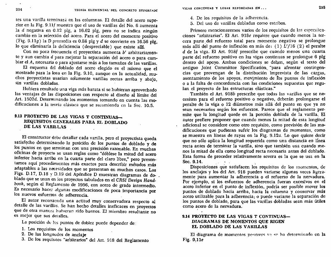
294 TEORIA ELEMENTAL- DEL CO!'lCRETO REFORZADC
tes una varilla terminará en las columnas. El detalle del acero superior en la Fig. 9.llf muestra que el uso de varillas del No. 6 aumenta la d negativa en 0.12 plg, a 16.62 plg, pero no se indica ningún cambio en la sele-cción del acero. Para el acero del momento positivo (Fig. 9.1lg) la D promedia es 0.88 plg y d se convierte en 16.56 plg, lo que eliminaría la deficiencia (despreciable) que existe allí.
Con no poca frecuencia el proyectista aumenta b' arbitrariament~ y aun cambia d para mejorar la separación del acero o para cambiar el A, necesaria o para ajustarse más a los tamaños de las varillas.
El esquema del doblado del acero elegido es el mismo que el mostrado para la losa en la Fig. 9.10, aunque en la actualidad, muchos proyectistas usarían solamente varillas rectas arriba y abajo sin varillas dobladas. - '
Hubiera resultado una viga más barata si se hubieran aprovechado las ventajas de las disposiciones con respecto al diseño al límite del Art. 1502d. Determmando los momentos tomando en cuenta las modificaciones a la teoría elástica que se recomienda en la Sec. 10.5.
9.13 PROYECTO DE LAS VIGAS T CONTINUASREQUISITOS GENERALES PARA EL DOBLADO DE LAS VARILLAS
. El constructor debe detallar cada vanlla, pero el proyectista queda sattsfE!cho determinando la posición de los puntos de doblado y de los puntos en que terminan con una precisión razonable. En muchas oficinas de proyecto se usan reglas como "dóblese la mitad del acero inferior hacia aniba en la cuarta parte del claro libre," pero presentamos aquí proceclirmcntos más exactos para describir métodos más a~aptables a las necesidades que se presentan en muchos casos. Las F1gs. D.17, D.18 y 0.19 del Apéndice D muestran diagramas de doblado que se usan en los proyectos tabulados en el CRSI Design Handbook, según el Reglamento de 1956, con acero de grado intermedio. Es necesario hace; algunas modificaciones de poca importancia por los nuevos esfuerzos de adherencia. .
El autor reco~ienda una actitud muy conservadora respecto al detalle de las varillas. Se han hecho detalles ineficaces en proyectos que de otra mam:ra huh1erar! sido buenos. El miembro resultante no es mejor que sus detalles.
La posición d<: !os puntos de doblez puede depender de:
l. Los requisitos de los momentos 2. De las longnudcs de anclaje 3. De los requisitos "arbitrarios" del Art. 918 del Reglamento
VIGAS CONTINUAS Y LOSAS REFORZADAS EN ••• 295
4. De los requisitos de la adherencia. 5. Del uso de varillas dobladas como estribos.
Primero mencionaremos varios de los requisitos de las cspeclfícaciones "arbitrarias". El Art. 918e requiere que cuando menos la tercera parte. del refuerzo total para momento negativo se prolongue más allá del punto de inflexión en más de: ( 1 ) L' 116 ( 2) el peralte d de la viga. El Art. 918f prescribe que cuando menos una cuarta parte del refuerzo positivo en las vigas continuas se prolongue 6 plg dentro del apoyo. Ambas condicione~ se deb.en, según el texto del antiguo Joint Committee Specificatióa_ "para afrontar contingencias que provengan de la distribución Imprevista de las cargas, asentamiento de los apoyos, movimiento de !Os puntos de inflexión o a la falta de concordancia con las condiciones supuestas que regulan el proyecto de las estructuras elásticas."
También el Art. 918b prescribe que todas las varillas que se necesiten para el refuerzo positivo o negativo, deberán prolongarse el peralte de la viga o 12 diámetros más allá del punto en que ya no sean necesarios según los esfuerzos. Parece que el reglamento permite que la longitud quede en la porción doblada de la varilla._' El autor prefiere proponer que cuando menos la mitad de esta longitud adicional se considere como otro requisito, como previsión de las modificaciones que pudieran sufrir los diagramas de momentos, como se muestra en líneas de rayas en la Fig. 9.12a. Lo que quiere decir que no sólo aplica la longitud requerida como una distancia en lÍnea recta antes de terminar la varilla, sino que también usa cuando menos la mitad de ella como longitud recta necesaria antes del doblado. Esta forma de proceder relativamente severa es la que se usa en la Sec. 9.14. ,
Disposiciones que satisfacen l~s requisitos de los momentos, de los anclajes y los del Art. 918 pueden variarse algunas veces ligeramente para aumentar la adherencia o el refuerzo de la nervadura. Por ejemplo, si los esfuerzos de adherencia fueran excesivos en el acero inferior en el punto de inflexión, podría ser posible mover los puntos de doblado hacia arriba, hacia la columna y conservar más acero utilizable para la adherencia; o puede variarse la separación de los puntos de doblado, para que las varillas dobladas sean más útiles como acero de la nervadura.
9.14 PROYECTO DE LAS VIGAS T CONTINUASDIAGRAMAS DE MOMENTOS QUE RIGEN EL DOBLADO DE LAS VARILLAS
El diagrama de momentos pO"I~Jvoc; v:~ "!' ha determinarlo en la Fig. 9,11e
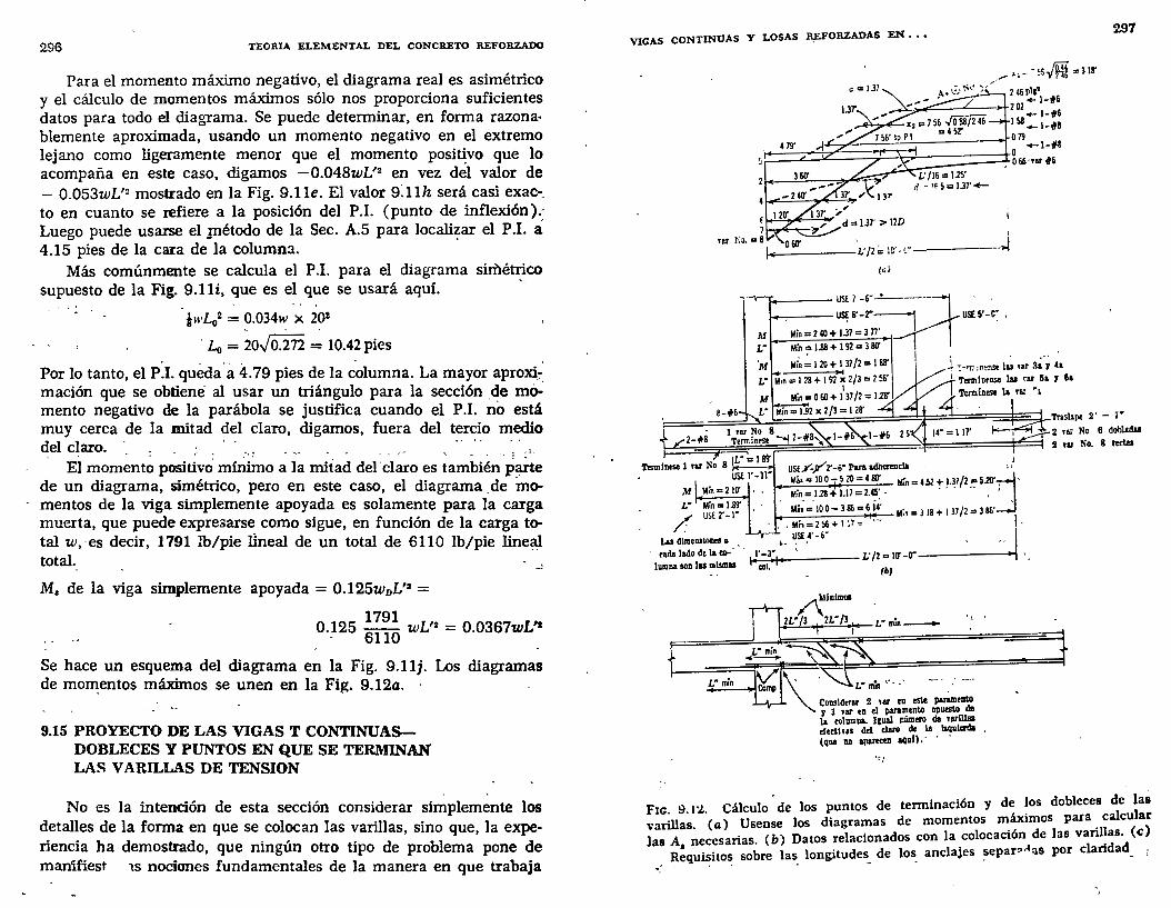
296 TEORIA ELEMENTAL DEL CONCRETO REFORZADO
Para el momento máximo negativo, el diagrama real es asimétrico y el cálculo de momentos máximos sólo nos proporciona suficientes datos para todo el diagrama. Se puede determinar, en forma razonablemente aproximada, usando un momento negativo en el extremo lejano como ligeramente menor que el momento posi~vo que lo acompaña en este caso, digamos - 0.048wL'2 en vez del valor de - 0.053wL'2 mostrado en la Fig. 9.1le. El valor 9:1lh será casi exac-_ to en cuanto se refiere a la posición del P.l. (punto de inflexión).; Luego puede usarse el Jllétodo de la Sec. A.5 para locali~ar el P.l. á 4.15 pies de la cara de la columna.
Más comúnmente se calcula el P .1. para el diagrama simétrico supuesto de la Fig. 9.11i, que es el que se usará aquí.
lwL02 = 0.034w X 202
' - -· L0 = 20J0.212 = 10.42 pies
Por lo tanto, el P~l. quecta'a 4.79 pies de la columna. La mayor aproxi;-, mación que se obtiene· al usar un triángulo para la sección .de me>-: mento negativo de la parábola se justifica cuando el P.I. no está muy cerca de la mitad del claro, digamos, fuera del tercio medio del claro. ·_ ·-
l~. ~ - - ~- ~ - ,_
El momento positivo mínimo a la mitad del' claro es también p~e de un diagrama, simétrico, pero en este caso, el diagrama . de momentos de la viga simplemente apoyada es solamente para la carga muerta, que puede expresarse como sigue, en función de la carga total w,·es decir, 1791 lb/pie lineal de un total de 6110 lb/pie linea:I total.
M, de la viga simplemente apoyada = 0.125woL'2 =
0.~25 ~~~~ wL'2 = 0.0367wL'1
Se hace un esquema del diagrama en la Fig. 9.1lj. Los diagramas de mo~entos máximos se unen en la Fi~. 9.12a. ·
9.15 PROYECTO DE LAS VIGAS T CONTINUASDOBLECES Y PUNTOS EN QUE SE TERMINAN LAS V ARILL.L\S DE TENSION
No es la intención de esta sección considerar simplemente los detalles de la forma en que se colocan las varillas, sino que, la experiencia ha demostrado, que ningún otro tipo de problema pone de manifiest 1s nociones fundamentales de la manera en que trabaja
VIGAS CONTINUAS Y LOSAS JI,EFORZADAS EN • • •
' 1+-----L'/2 ':le' -t ·---
(ao
__ ..¡
~-e,----~:~~~ . TI·~---- u~ r-~- , . Mín=240+ 1~7=377' ,
Mín = 1.88 + 1 92 = 3 80'
l ~ '!•'T.•,nenst 1~ nr 8~·; (a
1 Term 1 nense laa rar 3a 1 61 Termlntit la nz "•
297
~==~~~~~~~~~~==~~~======:==f~1-~u~ 2·-•· 2 ra; No 6 dob!Mal 2 ru No. 8 rectas
uSE.T'-Y2'-6' rara adherencia - ,! Má• = 10 O- 5 20 = 4 so: Min = U1 ~ ~-~7/2 .':' S.20'~, , ' Min = 118 + 1.17 = 2.45 • ,
lolá;- =· 10 O- 3 85 = 6 ii Min = 3 18 + 1 37/2 = 3 86' ' / , Min = 2 ~ + 11' = ,., ·
Lu dlmeDlllODf!U •. ~Sf ~· • ó' • · } '• · cad&ladodtla-·'· 1'-3' L'/Zalrt-rr-----+i..j
lumna aon lu mlsmU col. (1>)
'C,•
FIG. 9.11.. Cálculo 'de los puntos de tenninación y de Jos dobleces de las varillas. (a) Usense los diagramas de momentos máximos para. calcular )as A, necesarias. ( b) Datos relacionados con la colocación de las varillas. (e:)
·.' Requisitos_ sobre las_ longitudes_ de los anclajes ~epar:-~as por claridad_ :
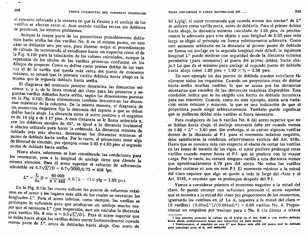
298 TEORIA I"LEMENT AL DEL CONCRETO REFORZADO
el c_oncreto reforzado y la manera en que la flexión y el anclaje de las vanllas se afectan entre sí. Aun usando varillas rectas sin dobleces se presentan los ~ismos problemas.
, Aun~ue la. mayor parte de los proyectistas probablemente doblanan hacia arn~a las dos varillas No. 6 en el mismo punto, en este ~aso_ se doblaran un~ por una, para ilustrar mejor el procedimiento
e c~lculo. Se recomienda al estudiante hacer un esquema como el de !: FI~--~.12b para ~a tabulación de los valores calculados, aunque la . pe?cwn de los títulos de las varillas provocan confusión en los
d~bujos de proyec_to. Como se define como primer doblez de las varill ... J _el de la varilla que queda más cerca del punto de momento m~o, se notará que la primera varilla doblada hacia abajo es ia misma q~e la segunda doblada hacia arriba.
. El diagrama del n;omento positivo determina las, distancias mírumas X¡ Y_ X2 de la lmea central del claro para las primeras y segundas _vanll~s dobladas hacia arriba, según las dimensiones puestas ~~la Fig_. 9.12b. Estas dimensiones también determinan las distan-
s máximas de la columna. De la misma manera el dia ama de ~~sb:;:o~e~tos ne_gativos_ fija la distancia del soport~ a que ~e deben
d r acia abaJo. La ~stancia entre el acero positivo y el negativo es ~ 14 plg o de 1.17 pies. A esta distancia se le llama ordenada y con o~ dob~e~es usuales de 45~, es igual a la distancia horizontaÍ o abscisa utilizada para. hacer la ordenada. La distancia mínima de doblado más esta abscisa, determinan las distancias minimas al pun_to de doblado ~~cia arriba. Por lo tanto, el proyectista tiene al o de libertad de elecoon; por ejemplo, entre 2.45 y 4 80 . 1 g punto de doblado hacia arriba. · pies a segundo
Hasta ahora, solamente se han considerado las condi . los mom t 1 . cwnes para
. en o~, pero a a longitud de anclaje tiene que dársele la rms~~ atención. Para el acero superior el esfuerzo de adherencia admisible es 6.7Vfc' ID = 6.7y3000/0.75 = 488 lpc.
L" = ]!!_ D- = 60 000 ~ _ .. 4u 4 x 488 X O.,:> -": :!3 O plg = 1._92 pit:s
En la Fig. 9.12c las cruces indican los puntos de esfuerzos máxi;nos. en el acero Y los lugares más allá de los cuales se necesitan las ongitudes L". Para el acero inferior, como siempre las varillas se
prolongan lo_ suficiente para que produzcan un anciaje much _ yor que :1 necesario L" (por inspección, aun sin calcular la dis~a:: para vanllas No. 8 con u= 9 5,,-f 'ID) p 1 .
d bl h . . . v e • ara e acero supenor que se o a acia abaJo, las varillas deben correr horizontalmente cuando menos parte de L". ant_es de doblarlas hada abajo. Con acero de
VIGAS CONTINUAS Y LOSAS REFORZADAS EN ••• 299
60 k/plg~. el autor recomienda que cuando menos dos tercios• de L" se utilicen como varilla recta, antes de doblarla. Para el primer doblez hacia abajo, la distancia mínima calculada de 1.28 pies, es precisamente la adecuada para este objeto y una longitud de 0.55 pies más larga se eligió al principio en forma relativamente arbitraria. Como este aumento arbitrario en la distancia al primer punto de doblado no forma un anclaje en la segunda longitud más difícil, la siguiente longitud L" puede medirse con seguridad desde la distancia mínima permisible (para momento) al punto del primer doblez, hacia abajo. t Lo que da el mínimo para anclaje al segundo punto de doblado hacia abajo como 1.28 pies + 1.92 X% = 2.56 pies.
En este ejemplo los dos puntos de doblado pueden satisfacer fácilmente todos los requisitos. Cuando un proyectista trata de doblar hacia arriba muchas varillas, lo que se acusa por las distancias necesarias que exceden de las distancias máximas disponibles. Esta condición indica que se ha elegido una forma de doblado incorrecta para ese miembro. Cuando, como en este ejemplo, existe una variación entre mínimo y máximo, lo que es una indicación de que el proyectista puede elegir arbitrariamente. También puede significar que se pudieran doblar más varillas si fuera necesario.
Para cualquiera de las 6 varillas No. 6 del acero superior que no se doblan hacia abajo, el anclaje necesario debe ser cuando menos de 1.88 + L" = 3.80 pies. Sin embargo, si se cortan algunas varillas dentro de la distancia al P.l. para el momento máximo negativo, debe satisfacerse la condición relativamente estricta del Art. 918c. Hasta que se conozca más con respecto al efecto de cortar las varillas en las zonas de tensión de las vigas, el autor prefiere prolongar estas varillas cuando menos hasta el P.l. que se produce con la mayor carga. Por lo tanto, no cortará ninguna varilla a una distancia menor que aproximadamente 4.79 pies del apoyo. No todas las varillas pueden cortarse ni aun en este P.I. El momento minimo a la mitad del claro requiere que algo se quede a todo lg largo del claro y el Art. 918b, e requiere que se prolongue después del P.I.
Vamos a considerar primero el momento negativo a la mitad del claro. Se puede obtener con suficiente precisión el acero superior que se necesita a la mitad del claro pcr proporciones de los momentos, ignorando los cambios en jd. La A. negativa a la mitad del claro = (8 varillas) (O.OlwL'z)/(0.091wL'~) = 0.66 varillas No. 6. Proporcionan un empalme por traslape para 1 No. 6 (la última u octava
• Los ganchos est;indar &e valúan en 19 k/plg• en el Art. 918h J una varilla doblada bada abajo, probablemente tenga una capacidad un poco mayor.
t Teóricamente. el requisito es una L• que Uegue mib allA del punto real de doblado pero calculado para el f• real reducido
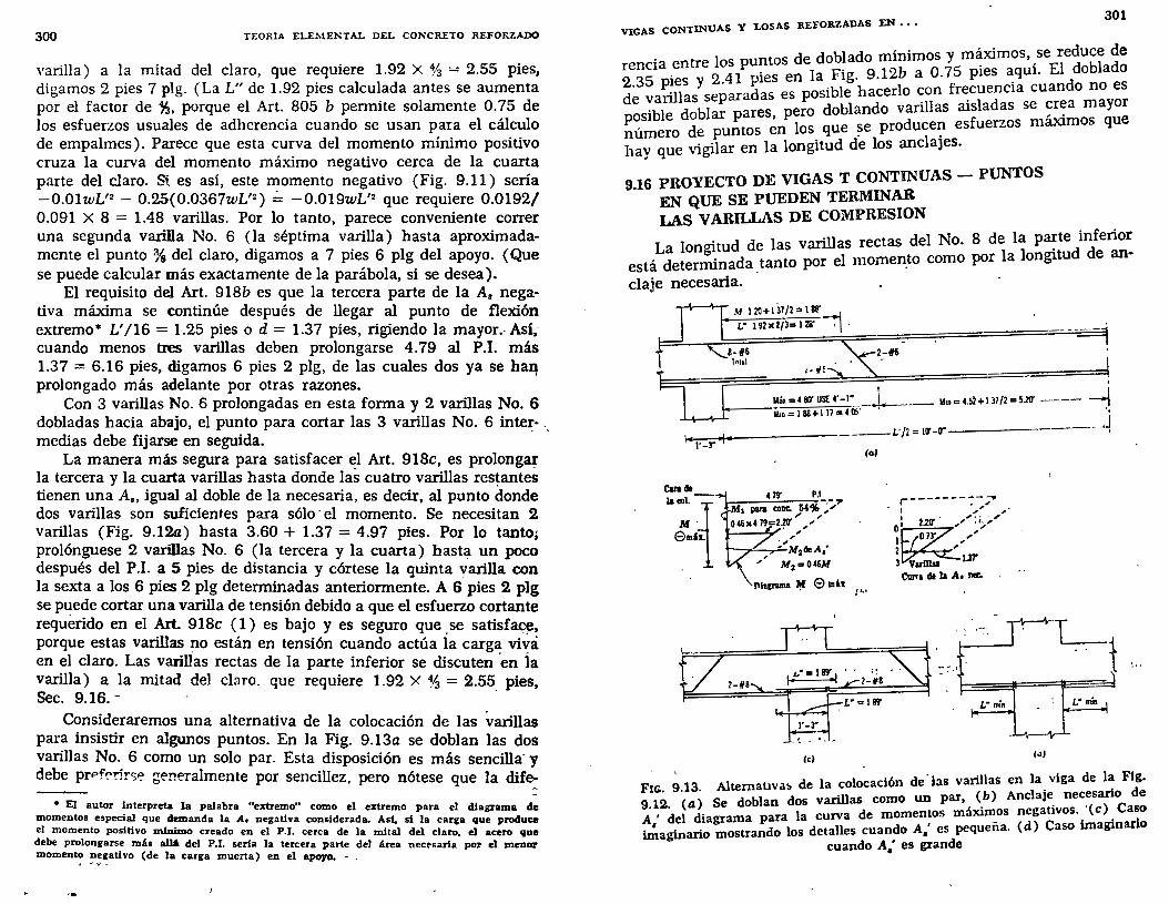
300 TEORIA ELEMENTAL DEL CONCRETO REFORZADO
varilla) a la mitad del claro, que requiere 1.92 X % = 2.55 pies, digamos 2 pies 7 plg. (La L" de 1.92 pies calculada antes se aumenta por el factor de ~. porque el Art. 805 b permite solamente O. 75 de los esfuerzos usuales de adherencia cuando se usan para el cálculo de empalmes). Parece que esta curva del momento mínimo positivo cruza la curva del momento máximo negativo cerca de la cuarta parte del claro. Si es así, este momento negativo (Fig. 9.11) sería -0.01wL'2 - 0.25(0.0367wL'2 ) ~ -0.019wL'2 que requiere 0.0192/ 0.091 X 8 = 1.48 varillas. Por lo tanto, parece conveniente correr una segunda varilla No. 6 (la séptima varilla) hasta aproximadamente el punto %del claro, digamos a 7 pies 6 plg del apoyo. (Que se puede calcular más exactamente de la parábola, si se desea). ·
El requisito del Art. 918b es que la tercera parte de la A. negativa máxima se continúe después de llegar al punto de flexión extremo• L'/16 = 1.25 pies o d = 1.37 pies, rigiendo la mayor.- Así,cuando menos tres varillas deben prolongarse 4.79 al P.l. más 1.37 = 6.16 pies, digamos 6 pies 2 plg, de las cuales dos ya se h~ prolongado más adelante por otras razones.
Con 3 varillas No. 6 prolongadas en esta forma y 2 varillas No. 6 dobladas hacia abajo, el punto para cortar las 3 varillas No. 6 inter- -. medias debe fijarse en seguida.
La manera más segura para satisfacer el Art. 918c, es prolongar la tercera y la cuarta varillas hasta donde las cuatro varillas res~antes tienen una A., igual al doble de la necesaria, es decir, al punto donde dos varillas son suficientes para sólo· el momento. Se necesitan 2 varillas (Fig. 9.12a) hasta 3.60 + 1.37 = 4.97 pies. Por lo tanto; prolónguese 2 varillas No. 6 (la tercera y la cuarta) hast~ un poco después del P.I. a 5 pies de distancia y córtese la quinta varilla con la sexta a los 6 pies 2 plg determinadas anteriormente. A 6 pies 2 plg se puede cortar una varilla de tensión debido a que el esfuerzo cortante requerido en el Art. 918c ( 1) es bajo y es seguro que. se satisfac;~, porque estas varillas no están en tensión cuando actúa la carga viva en el claro. Las varillas rectas de la parte inferior se discuten ·en Ía varilla) a la mitad del cl:1ro. que requiere 1.92 X % = 2.55 pies, Sec. 9.16.- ·
Consideraremos una alternativa de la colocación de las variiias para insistir en algunos puntos. En la Fig. 9.13a se doblan las dos varillas No. 6 como un solo par. Esta disposición es más sencilla· y debe prPf?!'irse ge!'!eralmente por sencillez, pero nótese que la dife:
• El autor interpreta la palabra uelrtremo" como el extremo para el diagrama de momentos especial que demanda la A. negativa considerada. Asf. st la carga que produce el momento positivo mfnimo creado en el P.I. cerca de la mita! del claro, el acero que debe prolongarse más aiH del P.I. seria la tercera parte del área neceoaria por el menor momento negativo (de la carga muerta) en el apoyo. -.. ... ... ~
VIGAS CONTINUAS y LOSAS REFORZADAS EN • • • 301
rencia entre los puntos de doblado minimos y5m~ximos, _se~e~~~fa~~ 2 35 . 2 41 pies en la Fig. 9.12b a 0.7 pies aqUl. d · va~~~sy separadas es posible hacerlo con frecuencia cuando no es ~sible doblar pares, pero doblando varillas aisladas se ~r~a mayor ~úmero de puntos en los que ~e produce':l esfuerzos max1mos que hay que vigilar en la longitud de los anclaJeS.
9.16 PROYECTO DE VIGAS T CONTINUAS - PUNTOS EN QUE SE PUEDEN TERMINAR LAS VARilLAS DE COMPRESION
La longitud de las varillas rectas del No. 8 de la p~te inferior está determinada tanto por el momen_to como por la long¡tud de an· claje necesaria.
..,-\~\-r 1\f 1 2ll + 1 37/2 "' 1 ~
1'-T
L" 192X2/3=128'
8-f6 l•ul
2-~
l-IlE . Mú=4811"Ust:4"-l" __ l_ __ J!on=U~+I37/2=S.20' ----- ---4 Moo = 1 88 + 1 17 = 4 0!:' • ·,
L'/Z= ur-rr---------- -·~ (t>l
r---------~ 1 ",,,, , 1 • ,. C" • ,
0, 22~ ,' -~,
1~73' ,"' 2 " 3 var111a1 ur
Cuna de la A • na:.
- ........ - .. -1<1 Co1J
FIG ~ 13 Altemat1vat. de la colo~ación de "l:ls varillas en la viga de la Ftg.
9 12, ·(a) Se doblan dos varillas como un par, (b) Anclaje. necesario de A • del diagrama para la curva de momentos máximos negativos .. '(e). Caso ~aginario mostrando los detalles cuando A,' es pequeña. (d) Caso unagmarlo
cuando A.' es grande

•
302. TEORIA ELEMENTAL DEL CONCRETO REFORZADO
Como se necesitan más de dos varillas en cada cara de la columna, son necesarias las varillas de ambas vigas adyacentes. Una l.J'o. 8 debe atravesar la columna y prolongarse la longitud de anclaje más allá de la cara más lejana. Esta prolongación debe comprobarse para ver si tiene la longitud necesaria para el momento, para lo cual se requiere un diagrama de momentos para el acero de compresión. En la Sec. 9.10 se obtuvo el valor de M1 sin acero de compresión de 133.3 k-pies, que es 133.3/247 = 0.54 del M total. Por lo tanto, el diagrama de momentos negativos puede dividirse, como se muestra en la Fig. 9.13b, con solamente 2.20 pies (más una distancia d) sin necesitar acero de compresión. Las dos varillas No. 8 que corren a lo largo de todo el claro pueden ser suficientes para el mismo menos en 0.73 + 1.37 = 2.10 pies adyacentes al apoyo. Esta longitud en este ejemplo rige sobre la longitud L" más corta que se determina en el párrafo siguiente y requiere que se prolongue una varilla de cada lado a través de la columna y 2.10 pies más allá de la cara lejana, como se indica en la Fig. 9.12b. No es necesaria una de las varillas de cada lado más allá de la cara de la columna y puede simplemente prolongarse la longitud L" dentro de la columna y cortarse.
El proyecto de A.' en la Sec. 9.10 se basa en f,' = 47.3 k/plg1 ,
que, con el esfuerzo permisible de adherencia [Art. 1801c(3)] en compresión de 13v'fc' se requiere
L" = f,'D/4u = 47 300 X 1.00/( 4 X 13y3000) = 16.6 plg = 1.39 pies
Además, es necesario tomar en cuenta otras circunstancias, porque para la separación transversal, se requiere que las varillas No. 8 se aten en grupos de dos dentro de la columna• y, generalmente, se considera que esto reduce el perímetro. El análisis exacto es difícil, porque la superficie expuesta es invariable. Como un margen razonable para esta complicación, L" simplemente se alargará 6 plg más a los 1.89 pies. Se espera que la varilla que continúa a través de la columna mantenga su esfuerzo al cruzar la columna y que necesite su L" más allá de la cara lejana de la columna. La otra, al prolongarse L" más allá de la cara cercana, se prolonga ligeramente más allá del lado lejano de la columna, pero esta prolongación dentro del claro siguiente, donde no se necesita, puede con toda razón ignorarse en el análisis de ese claro. - .
Con mucha frecuencia la colocación del acero de compresión puede ser más sencilla. Si se han necesitado 4 varillas No. 8, ambas varillas de un lado podían haber terminado en un punto, como en la Fig. 9.13d. Este punto debe también satisfacer los requisitos de momento y de longitud de anclaje. Todavía hubiera resultado más senci1la la colocación
• O colocar el acero en dos CapaL
VIGAS CONTINUAS Y LOSAS REFORZADAS EN •• • 303
si solamente se hubieran necesitado 2 varillas No. 8 para A,' como se muestra en la Fig. 9.13c. Entonces no hubiera sido necesario el acero adicional de compresión del claro adyacente y sólo es necesario prolongar, dentro de la columna, la distancia L". Entonces el diagrama de momentos no tiene aplicación para determinar la longitud de estas varillas rectas inferiores, porque automáticamente se usa toda la A.' en toda la longitud del diagrama de momento negativo.
Como anteriormente, para los atados de varillas dentro de la columna, deberá usarse la longitud L" de 1.89 pies. Otra forma de considerar este armado pudiera ser traslapando varillas como empalmes en compresión, que requieren 24D = 2.00 pies de traslape. En las columnas gruesas, la diferencia entre los dos procedimientos pudiera ser notable; aquí la diferencia es pequeña. El autor no le considera importancia a la capacidad horizontal de compresión cerca de la mitad de la columna (donde probablemente el peralte efectivo aumenta) y considera L" de la cara de entrada como el aspecto de importancia crítica.
9.1 'Z PROl.'ECTO DE VIGAS T CONTINUAS-ADHERENCIA POR FLEXION EN EL ACERO DE TENSION
En la Fig. 9.14 se marcan los puntos de esfuerzos máximos de adherencia por flexión. Se llama la atención al Art. 180la que dice que las varillas dobladas no más de d/3 del acero longitudinal, pueden contarse en el perímetro. Por lo tanto, los esfuerzos críticos de adherencia por flexión en el acero superior se calcularán a una distancia d/3 más allá de los puntos de doblado y, precisamente, más allá de los puntos de corte. Aunque el Reglamento no lo exige en los claros interiores, el autor continuarla usando el esfuerzo cortante correspondiente a una viga simplemente apoyada aumentado en 0.08wL' /2 = 4880 lb para representar el corte debido a la continuidad, cuando se trate de acero determinado por el momento negativo. Se usará la Ec. 6.3 para comprobación.
En el punto 1 (varillas superiores):
VI = 1.0811'L'/2 = 1.08 X 6110 X 20/2 = 65 700 lh.
P, = 65 700/0.85 = 77 300 lb
Ec. t1.4. Mín N= Pf(QJJ.'-rr x 0.9d) = 77 300/(6.7 X .)3000 X 3.14 X 0.9 X 16.62)
= 4.53 varillas < 8 rorr.

304 TEORIA ELEMENTAL DEL CONCRETO REFORZADO
1 E , 7' -6• ---------- ---
,_)¡..-Ji...-.-*---- s· -o·--- - ~ 1
4.50 - 1.17 ;, 3.33' 0.46' 1 -j Termmar -..'1 Terminar 2 Terminar • 2 ranllas
® ®
------ L'/2 = 10'-0"------ -~ - -
FIC. 9.14. Lugares en los que se debe comprobar la adherencia por tteXIón
_ -Es evidente que las siete varillas en el punto 2 y las 6 del punto 3_ son adecuadas. porque V será menor en estos casos. El punt~- 4 queda en el punto de ínflexión y lleva tensión en las varillas solamente cuando el diagrama de momentos varía. En cualquier caso, las cuatro varillas restantes son adecuadas porque V no puede ser mayor del 55 o 60% del máximo en el punto 1 y, por lo tanto, la N necesaria no puede ser mayor de 55 o 60% de 4.53 .. Eri ·tos· puntos 5 y 6 existe tensión solamente cuando la carga viva queda fuera del claro y V es evidentemente demasiado pequeña para darle importancia. .
Las · varillas inferiores están a- la tensión máxima cuando· '}á
carga es simétrica, lo que anula el esfuerzo cortante producido por continuidad.· La fuerza cortante aumenta hacia el apoyo y ·el número de varillas disminuye; por lo tanto, el lugar peor está en· el punto de ínflexión para momento máximo positivo (a. la izquierda de este punto 7 las varillas están en compresión y las relaciones. de adherencia por .flexión del Cap. 6 se aplican solamente para las varillas _en tensi_Ó;ft).
V7 = 61 10 x 7.56 = 46 200 Ib, P = 46_200/0.85 = 54 300 lb
N= PJ(QJ1}7T X 0.9d} -.
=54 300/(9.SJ3ooo x 3.14 x 0.9 x 16.56) = 2.24varillas > 2reales . . . Según la experiencia del autor, en este punto siempre ha sido crítica si la adherencia constituye un problema en algún lugar. Porque resultaría muy molesto a esta etapa poner tres varillas, investigar si la última varilla doblada puede ayudar aquí. Se dobló arriba de 3.0 pies del apoyo, pero se puede contar hasta que esté a d/3 = 0.46 del acero superior. n'lr lo tanto, están disponibles tres varillas a 2.54 pies del
•
VIGAS CONTINUAS Y LOSAS REFORZADAS EN • •·• 305
apoyo 0 7.46 pies de la mitad del claro. Que está t~n ce_rca del_ pun~o de inflexión que se puede despreciar esta pequena diferencia. ~m embargo, el punto de doblado se puede mover ha~ia el apoyo (Fig. 9.12b) sin más complicaciones. Por lo tanto, revisese el punto de doblado hacia arriba a 3 pies O plg, a 2 pies 6 plg de la columna, lo que todavía satisface el valor mínimo de 2.45 pies. -
9.18 PROYECTO DE VIGAS T CONTINUAs-ESTRIBOS
Como. en 1~ Sec. 9.12 se ~ligieron atados de varillas, son necesarios los estribos hasta la mitad de la viga para satisfacer el Art. 804f del Reglamento. Sin embargo, ~os es.tribos s~ consideran como una cuestión del proyecto por esfuerzo cortante.
Bajo el efecto de las cargas que producen los momentos _máximos, la viga está sujeta a una fuerza cortante en el extrem~ Igual a la de una viga simplemente apoyada wL' /2 = 61 000 lb, mas u~a fuerza cortante por contínuidad, que de nuevo _supondreml?s Ig_u~. ,a 0.08wL' /2 0 4880 lb,· actuando amba_s en el extremo ~ a la nutad del claro como- se muestra con líneas de rayas en la Fig. 9.15~. La fuerza cortante a la mitad del claro será mayor cuando se ~UI~e la carga viva de la mitad izquierda del claro. E:ta carga. produ~rrá _una fuerza cortante por continuidad más pequena, que se despreciará. Esta fuerza cortante en la viga ·simplemente apoyada será de. 4320 x 10 x 5/20 = 10 800 lb. En la Fig., _9.15a la linea ~ena se us:n-á como diagrama de fuerzas· cortantes máximas para ·proyectar los estribos. Con b' = 9.5 plg y d = 16.62 plg en ~1 extremo, la fuerza cortante crítica está a la distancia d 'del apoy~; · '-
= 66 000/0.85 = 495 ipc ' d' 9.5 X 16.62
'; . ies = 10 S00/0·85 = 81-lpc L¡u p 9.5 X 16.56
La pend!Cnte del diagrama de ves (495- 81 )/120 =345 lpc/ plg. El esfuerzo cortante crítico está a 16.5 plg del apoyo Y es de 495 - 3.45 x 16.6 = 438 lpc. En la Fig. 9.15b está dibujada la curva del esfuerzo cortante. Los estribos se necesitan en la longitud L., donde ves mayor de 2yf/; además de una longitud adicional igual a d = 16.6 plg, según el Art. 1702. Por lo tanto, los estribos son necesarios a lo largo de todo el claro, porque Lr + d = 112 + 16.6 = 128.6 plg > 10 pies. Así queda satisfecho au•-'Tláticamente el
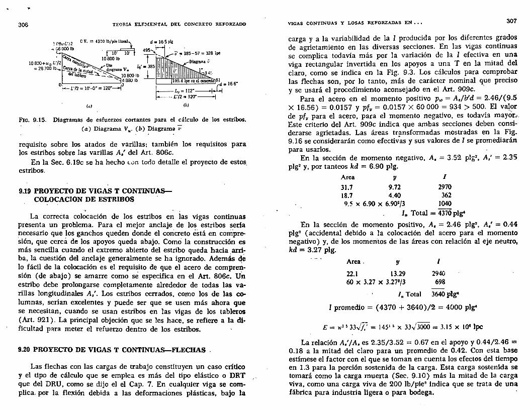
...
306 TEORIA ELE:\iENTAL DEL CONCRETO REFORZADO
! 09u·L'/2 _. G6000 lb
10800 lb ....__ _____ ____,4 880 lb
0~r·n = 1o--o· = 120"--l.>
d = 16 5 Plt
'-----'----=-----' d = 16 6" Lv= 112" .¡.(¡ L'/2 = 120"----\
(b)
Fic. 9.15. Diagramas de esfuerzos cortantes para el cálculo de los estribos.
(a) Diagrama V,.. (b) Diagrama 'i7
requisito sobre los atados de varillas; también los requisitos para los estribos sobre las varillas A,' del Art. 806c.
En la Sec. 6.19c se ha hecho (.un tono detalle el proyecto de estos_ estribos.
9.19 PROYECTO DE VIGAS T CONTINUASCOLOCACION DE ESTRIBOS
La correéta colocación de los estribos en las vigas continuas presenta un problema. Para el mejor anclaje de los estribos seria necesario que los ganchos queden donde el concreto éstá en compresión, que cercá de los apoyos queda abajo. Como la construcción es más sencilla cuando el extremo abierto del estribo queda hacia. arri~ ha, la cuestión del anclaje generalmente se ha ignorado. Además de lo fácil de la colocación es el requisito de que el acero de comprensión (de abajo) se amarre como sé especifica en el Art. 806c. Un estribo debe prolongarse completamente alrededor de todas las varillas longitudinales A,'. Los estribos cerrados, como los de las columnas, serían excelentes y puede ser que se usen más ahora que se necesitan, cuando se usan estribos en las vigas de los tableros (Art. 921 ). La principal objeción que se les hace, se refiere a la dificultad para meter el refuerzo dentro de los estribos.
9.20 PROYECTO DE VIGAS T CONTINUAS-FLECHAS .
Las flechas con las cargas de trabajo constituyen un caso crítico y el tipo de cálculo que se emplea es más del tipo elástico o DRT , que del DRU, como se dijo el el Cap. 7. En cualquier viga se complica. por la flexión debida a las deformaciones plásticas, bajo la
VIGAS CONTINUAS Y LOSAS REFORZADAS EN ••• 307
carga y a la variabilidad de la 1 producida por los diferentes grados de agrietamiento en las diversas secciones. En las vigas continuas se complica todavía más por la variación de la 1 efectiva en una viga rectangular invertida en los apoyos a una T en la mitad del claro, como se indica en la Fig. 9.3. Los cálculos para comprobar las flechas son, por lo tanto, más de carácter nominal que preciso y se usará el procedimiento aconsejado en el Art. 909c. ,
Para el acero en el momento positivo Pw = A,fb'd = 2.46/(9.5 X 16.56) = 0.0157 y p{11 = 0.0157 X 60 000 = 934 > 500. El V~?r de p{11 para el acero, para el momento negativo, es todavía mayor.'. Este criterio del Art. 909c indica que ambas secciones deben considerarse agrietadas. Las áreas tr~nsformadas mostradas en la Fig. 9.16 se considerarán como efectivas y sus valores de 1 se promediarán para usarlos.
En la sección de momento negativo, A. = 3.52 plg2, A,' = 2.35
plg2 y, por tanteos kd = 6.90 plg.
Area y 1
31.7 9.72 2970 18.7 4.40 362 9.5 X 6.90 X 6.902/3 1040
In Total = 4370 plgt
En la seccwn de momento positivo, A, = 2.46 plg=, A,' = 0.44 plg2 (accidental debido a la colocación del acero para el momento negativo) y, de los momen-tos de las áreas con relación al eje neutro, kd = 3.27 plg.
Area _ y 1
22.1 13.29 2940 60 X 3.27 X 3.272/3 698
In Total 3640pl~
1 promedio = ( 4370 + 3640)/2 = 4000 plgt
¡- ¡---E= w1 ~ 33v/,' = 1451 ~ x 33v 3000 = 3.15 X JOS lpc
La relación A,'/A. es 2.35/3.52 = 0.67 en el apoyo y 0.44/2.46 = 0.18 a la mitad del claro para un promedio de 0.42. Con esta base estímese el factor con el que se toman en cuenta los efectos del tiempo en 1.3 para la porción sostenida de la carga. Esta carga sostenida se tomará como la carga muerta (Sec. 9.10) más la mitad de la carga Viva, como una carga viva de 200 lb/pie: indica que se trata de una fábrica para industria ligera o para bodega.
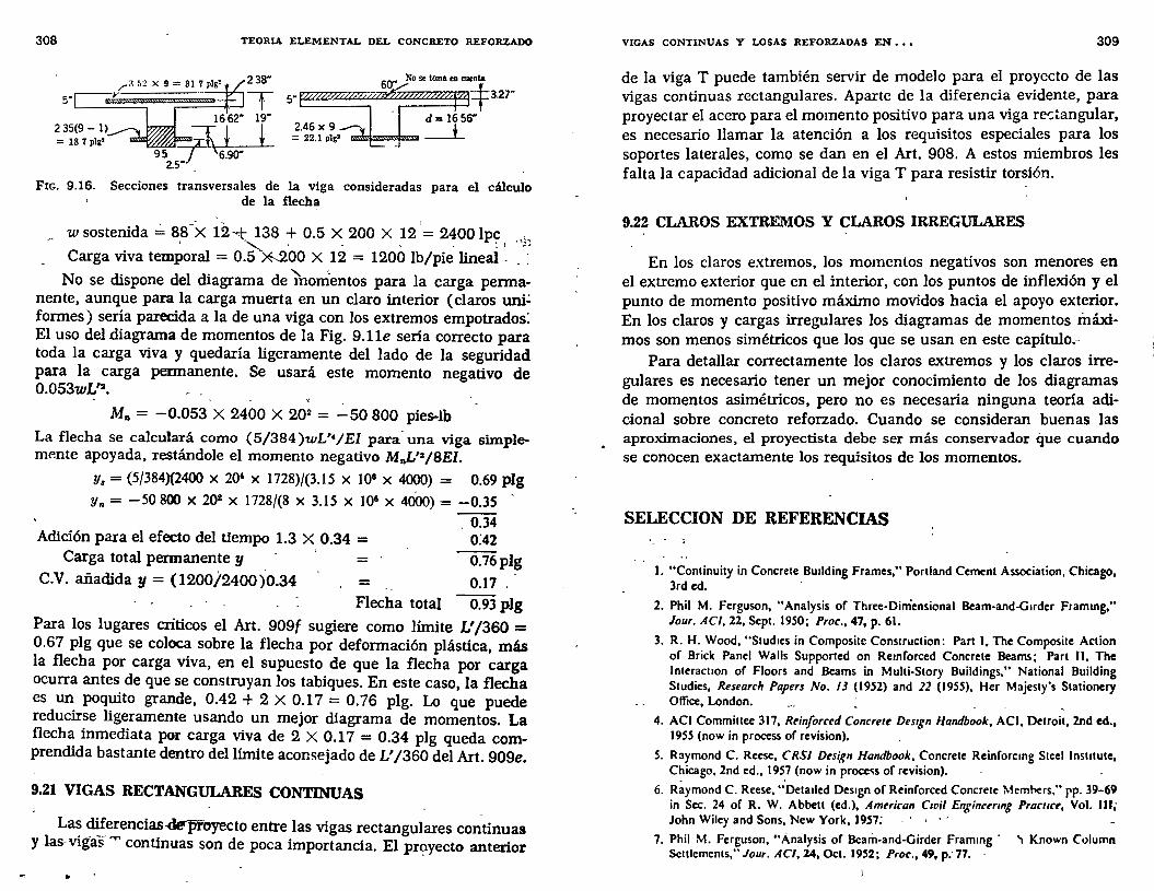
308 TEORIA ELEMENTAL DEL CONCRETO REFORZADO
2.46 X 9 = 22.1 plg'
FIG. 9.16. Secciones transversales de la viga consideradas para el cálculo de la flecha
w sostenida~ 88-X 12--.t 138 + 0.5 X 200 X 12 '= 2400 lpc ' .. ~ ' , - • ~ 1 ·'b
Carga viva temporal = 0.5 ~00 X 12 = 1200 lb/pie lineal .
No se dispone del diagrama de fuomentos para la carga permanente, aunque para la carga muerta en un claro interior (claros un1.: formes) sería parecida a la de una viga con los extremos empotrados: El uso del diagrama de momentos de la Fig. 9.11e sería correcto para toda la carga viva y quedaría ligeramente del lado de la seguridad para la carga permanente. Se usará este momento negativo de 0.053wL'2•
M"= -0.053 X 2400 X 202 = -50 800 pies-lb
La flecha se calculará como (5/384)wL'•JEI para· una viga simplemP.nte apoyada, restándole el momento negativo MnL'2/8EI.
y, = (5/384){2400 X 20' X 1728)/(3.15 X 108 X 4000) = 0.69 plg y,.= -50800 X 202 X 1728/(8 X 3.15 X 108 X 400o) = -0.35
Adición para el efecto del tiempo 1.3 X 0.34 = Carga total permanente y =
C.V. añadida y= (1200/2400)0.34 =
0.34 0:42
0.76plg
0.17 o
Flecha total 0.93 plg Para los lugares críticos el Art. 909f sugiere como límite L' /360 = 0.67 plg que se coloca sobre la flecha por deformación plástica, más la flecha por carga viva, en el supuesto de que la flecha por carga ocurra antes de que se construyan los tabiques. En este caso, la flecha es un poquito grande, 0.42 + 2 X 0.17 = O. 76 plg. Lo que puede reducirse ligeramente usando un mejor diagrama de momentos. La flecha inmediata por carga viva de 2 X 0.17 = 0.34 plg queda comprendida bastante dentro del límite aconsejado de L' /360 del Art. 909e.
9.21 VIGAS RECTANGULARES CONTINUAS
Las di_ferencias-.c:Jerpfoyecto entre las vigas rectangulares continuas y las- vigas 'T" continuas son de poca importancia. El pr~yecto anterior
..
VIGAS CONTINUAS Y LOSAS REFORZADAS EN ••• 309
de la viga T puede también servir de modelo para el proyecto de las vigas continuas rectangulares. Aparte de la diferencia evidente, para proyectar el acero para el momento positivo para una viga re-:~angular, es necesario llamar la atención a los requisitos especiales para los soportes laterales, como se dan en el Art. 908. A estos miembros les falta la capacidad adicional de la viga T para resistir torsión.
9.22 CLAROS EXTREMOS Y CLAROS IRREGULARES
En los claros extremos, los momentos negativos son menores en el extremo exterior que en el interior, con los puntos de inflexión y el punto de momento positivo máximo movidos hacia el apoyo exterior. En los claros y cargas irregulares los diagramas de momentos máximos son menos simétricos que los que se usan en este capítulo,,
Para detallar correctamente los claros extremos y los claros irregulares es necesario tener un mejor conocimiento de los diagramas de momentos asimétricos, pero no es necesaria ninguna teoría adicional sobre concreto reforzado. Cuando se consideran buenas las aproximaciones, el proyectista debe ser más conservador que cuando se conocen exactamente los requisitos de los momentos.
SELECCION DE REFERENCIAS '- - ~
l. "Continuity in Concrete Building Frames," Portland Cement Association, Chicago, Jrd ed.
2. Phil M. Ferguson, "Analysis of Three-Diniensional Beam-and-Guder Frammg," Jour. ACI, 22, Sept. 1950; Proc., 47, p. 61.
3. R. H. Wood, "Stud1es in Composite Construction: Part 1, The Composite Action of Brick Panel Walls Supponed on Remforced Concrete Beams; Part 11, The lnteracuon of Floors and Beams in Multi-Story Buildings," National Building Studies, Research Papers No. 13 (1952) and 22 (1955), Her Majesty's Stationery Office, London. ·
4. ACI Committee 317, Reinforced Concrete Des1gn Handbook, ACI, Detroit, 2nd ed., 1955 (now in process of revision).
S. Raymond C. Reese, CRSJ Design Handbook, Concrete Reinforcmg Stcel lnstnute, Chicago, 2nd ed., 1957 (now in proce~s of revision).
6. Ráymond C. Reese, .:DetaJied Des1gn of Reinforced Concrete Meml-.ers," pp. 39-69 in Sec. 24 of R. W. Abbett (ed.), American Civil Enginurmg Pracllce, Vol. 111; John Wiley and Sons, New York, 1957: . · ·
7. Phil M. Ferguson, "Ánalysis of Beam-and-Girder Frammg · '1 Known Column Settlements," Jour. AC/,24, Oct. 1952; Proc., 49, p:77 .
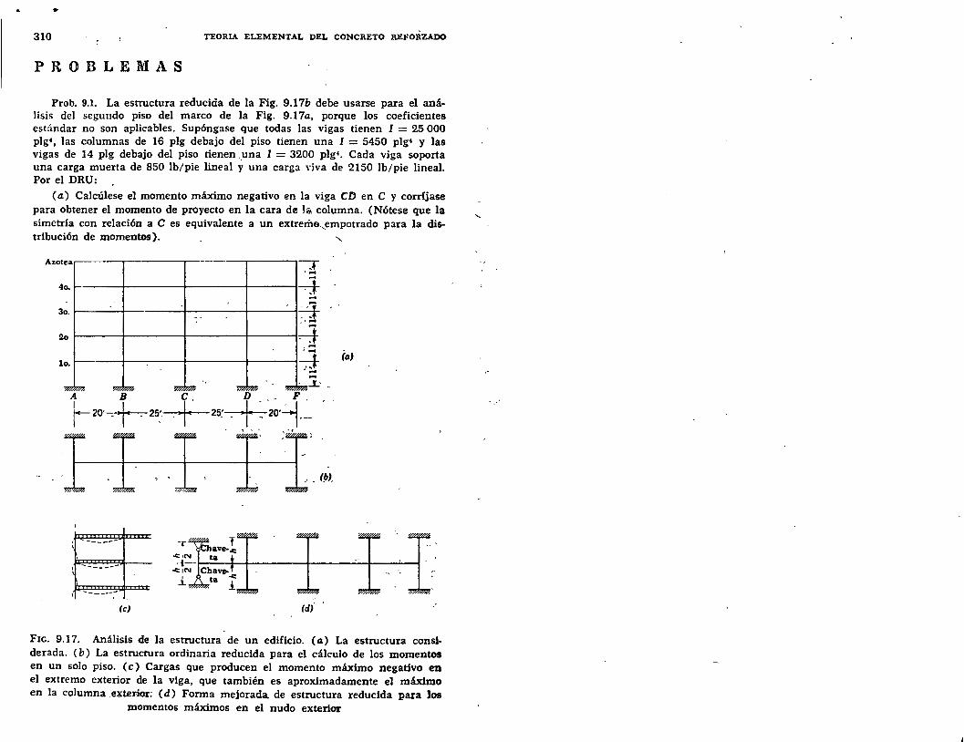
•
310 TEORIA ELEMENTAL DEL CONCRETO REFORZADO
PROBLEMAS
Prob. 9.1. La estructura reducida de la Fig. 9.17b debe usarse para el análisis del segundo piso del marco de la Fig. 9.17a, porque los coeficientes estándar no son aplicables. Supóngase que todas las vigas tienen 1 = 25 000 plg•, las columnas de 16 plg debajo del piso tienen una 1 = 5450 plg• y las vigas de 14 plg debajo del piso tienen -.una 1 = 3200 plg•. Cada viga soporta una carga muerta de 850 lb/pie lineal y una carga \'iva de 2150 lb/pie lineal. Por el DRU:
(a) Calcúlese el momento máximo negativo en la viga en en C y corríjase para obtener el momento de proyecto en la cara dl!l la columna. (Nótese que la simetría con relación a C es equivalente a un extrerila,empotrado para la dis-tribución de momentos). "
Azotea """T .... 4o. 4 ... 3o. 4 - --2o ~ .... . ...
(a) lo. -i-
1 -------\
______ ...
(e}
FIG. 9.17. Análisis de la estructura de un edificio. (a) La estructura considerada. ( b) La estructura ordinaria reducida para el cálculo de los momentos en un solo piso. (e) Cargas que producen el momento máximo negativo en el extremo exterior de la viga, que también es aproximadamente el máximo en la columna _exterior; (d) Fonna mejorada de estructura reducida para los
momentos máximos en el nudo exterior

..
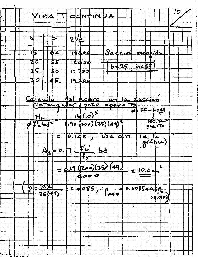
-..J~l A .:::S J. )I:.J ,e ~
-------,----------------,----------r---, -i --¡ ---,---, --r-;--T-1--¡-r] 1---4-~l--l--f-+-+-+--+-+-+-+---1-t--+-t----+---1----r------~--!-L ~-t-1-r -t----~--:--,
: -r---irl : 1
~--+-----4-l-----+-----+-+-+--+-+-+-----1---+-l-+---1~-t-+--~' +-+-+--+-t--+--t--1--t--t--t--t--t--t-----1--
~~~-~~~~-+4-~~~-b-~t~~~~~-~~-+--~~4-~~
~-+--i-------+----11-i------+---+-~'""'~l/ +--+-b-+--+-+--+---'tl_ e; ~! ,l-r-~ !C' -1 ~!----t--t---+---+----+-11-t---+--1 ~ -¡1)/ 1 ~~~+-1~1~~~~~~~.:~,~~,~~4-~~--~-t--t--t--~~-,-~---+-+-+---1~--+-+-~-t-+-~-+--~-~~
~~ 1 /jiilr ~ L ¡o ~== ·(1:1 : ~-r ·a = \---
1
. ~ .
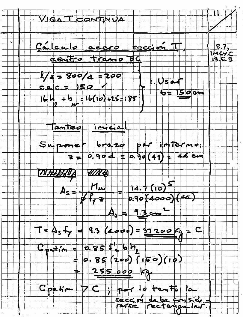
. 1-+--+--1---+~+-- !-- --- ¡_ -+--+--i-1--l--l--l----l--l--+--t---+---t-+--l--1-4--+--+---l-+------t-+-t--4--l-- -- ~-4-+--+----l
,
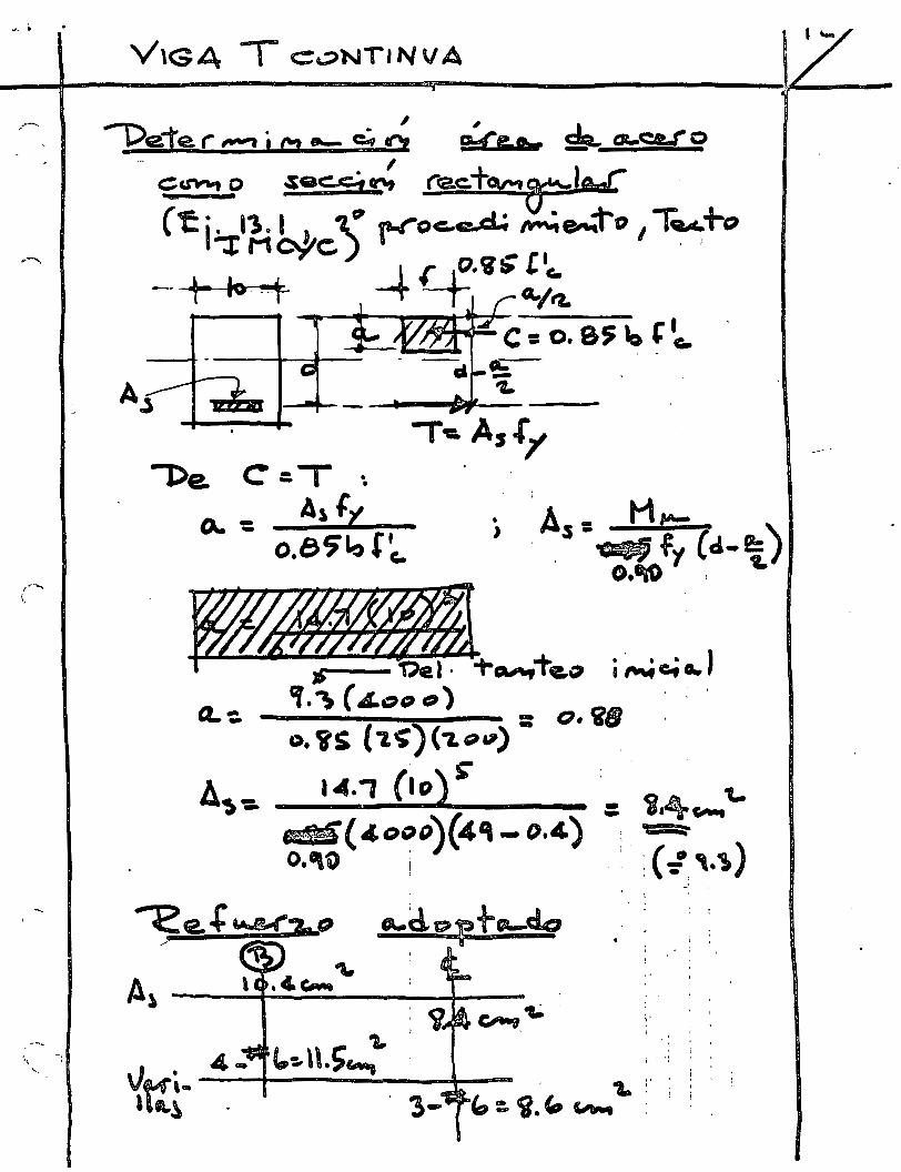
V\G4 T c:oNTINVA
j ..
1
' '
.. . A,. ---t-------4---~ .
~

<{
tn ->
f 1
+ • -• r-1
-
---------
--.
-
•' ,_ c:::a(
' .
. '

.--------
----~,_._
->--~•--'""-'
---·-----
~
-.. "~---
~.,._ -
.. .__ -
-~...,.. _
_ _
•
4: :> z ...... 1-z o ú
<l trJ ->
1
Í)'
"----.
---
...... --. ------. -----
_ _. __ ---~
----.---~-
~-.....----~ ··-------
....... _
~
~
. -' _,
• •
a o
---
•.
(
___ .._ ___ -
-~ ----------------~ ----- -
-------
~--------__ _. _____ -
--'
u ,..
--
u
( / /

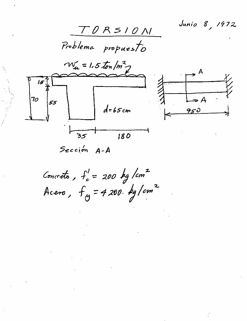
\ \
' \
e, '
( '
' " / 1
~' ¡'
1
7o 5'5
T () A :5 1 O 1\1
?roblernr;.. fropu-e~fo
'l-3.5
5 . f e c. CI.D'l'\ A-A
' J8D
Cuncr.e/i; 1 -F~ -=: :zoo }; /cm :t.
/+e~ 1 f (J ;: 1 ;l.fJ(J. 7/ ~:t.
J,..nlo 8 19 7 ;¿ .1
A
1 ·~ 1
1 1 1 1 1 1 1 1 ~
! 1 1 1 /' 1 ; 1
1 1
,, 1
\1 \_~
1 1 1 1 1 1 1 1 1 1 1 1 1 1 1 1 1 1 1 1 1 1 1 1 1 1 1 1
J
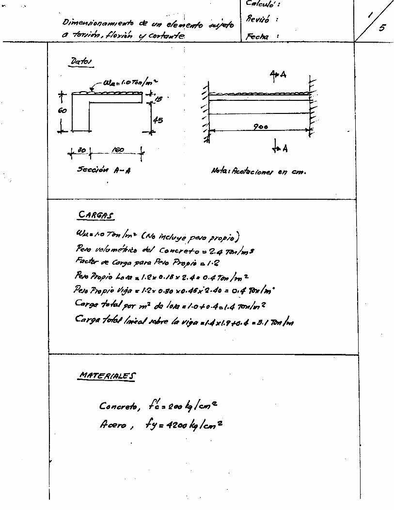
- '. C•lcu/0 ':
1 1 - -
Rew),J i . ' o [),;,~,~;,l)eu,,eNril e:#! v~ e~..,e..,n, ~~ 5 ' o *~,:~, sf'/gJr¡¡,k y C41,.h.y'e reekt :
--'
~q,b.l
_ fal.ce f.~r,;~~/~n"" tA r ,. '
t j:' ,.. >--- -i
"' ~-
GD \ ~ ' / ~·· 1 /i 9ee 1€ / ¡...- ~
~ ~A ~-t---~~t
Sc • ' eec¡~lll A-s4 M.~ 1 ~ele,~ e, cm. 1 .
CII!Ui'R.r
tUA. /·o r,., 4.. {No ,;,el~ y e ,PNtJ /~~;~~) ~~ v~/u,e?f~ tk/ Co~>rc~~-1-o = '2.4 ?i'H/_,1 ñl~ ~ C41':¡a ?"l't!l _R._,o ~ ..... ,» A 1·2
~ ,_o)"lo ¿,4:1 & ¡.~)t o./8,.. z.4• o.t~ r-1~ ~ P~~~ J>~r~p/o Yljt~ c- 1·'2..- Cl·ltJ wfJ.4~k:'2.#'/o = o'~" ?bl.-, • Corg~ 7-"-1 ?tJY "'2 flq lt~M, /.o .¡.,.4o.l·4 ?D>r/.., 'Z
Ce~r,pitTtnW ~a/~¿, l',.;¿t •/.1/x/.,,.tl·" a!I./1Att/,.,
M,fTeR/AJ.E" .J -Ct~,cre-ltJ, lt :J ~e/0 "'1 C#J ,_
/fef!!n;., ly:: 4'l~~~e.?~·
¡,.
1
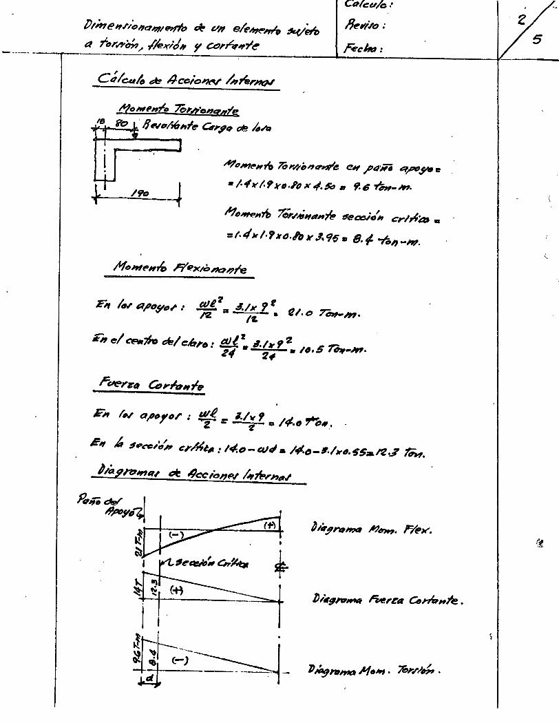
lJtlne,.l't'c,a,1~~ ~ VIl eii!"Ao7("'~ .1cV~ t:1 rt~l'htm, .f/exldll y Cd,r~~"~'~
.AfcMI'n~ 7CoJ-h'oJIIq«fe
.,..,t--fb-llfo' IJN~/JÓh-1~ C,;,q o~!! ¡{,A:J
C4Picu~ .•
IJ~ 1'/Jt:J :
r:ech:l:
"'?(1JI'1t-H1& ~,..,l'b"'1Q"~t! e~ ;'lffiii ~~J* e
•J.tf1t'/.,Jrt1•PIJXII/.~ • 9.8 ~-.M.
= 1· 4" 1· '1 xtJ.tftJ r .1. 96 • 8. 1- -r." -m.
F, ¡., ap~y~.l' •• .J!L!~ a 4./x 1 t e1. o reJIII-M· 12 /'L •
E, e/ ~¡h, tk/ t:.ltl'tJ: al/~ ;4,¡,, 2 ~~.G ~-M· Zt/ ~ti •
¡;;-~ ¡,.., 01'"/'tll' : ~< = 1./;, o /~.tJ rt,..,.
~~ J, ~.,.c-e,:,~ CI'A~t~: 14.D-aJtla l~tJ-I./Nt1.55:ai*ZJ ~.
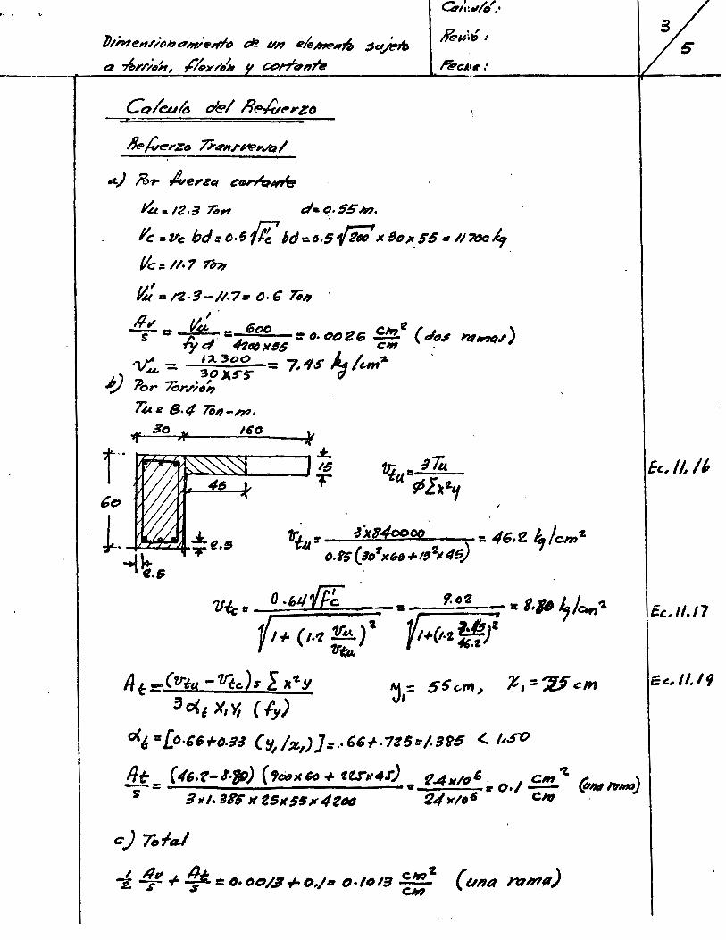
.. '
b/me,~;()ht:'-'lf/~,.;t) oe un 1?/e~~~~ :$e.tftlft
Q ~I'I';IJH, ~ ..... ,.¡,~ CCffcrHñ
fk.,(,.e,.zo á-cr~t.I"~I'.ID/
A.) .ñ>~ ~el'za t!"O"~~
14. 12.a 7iJ, d•I!J. 55_.,,
/'e ctl'e bd:o.t;li[' ;de.D.5fj;l JC8t1Jf_55•/l?col,
tlcal/·7 rn,
fl: • t"Z·'5-I/.7e O·~ 'Ttlh
,/¡,., u.'' 6 ~ -s e: .¡y~ = 4-t 00 = fJ, t>D 2 S ClrJ ( tJitJs IV,.,q./') ~1158 e, .
·V: - 1 ~ 3oo : 7. 4S J, .. /un2. , """ - 30 )1.5"'5"' " (]
í) .il'or 7órcl';.,~ Uc. 8·4 70'1-h?·
IGO
¡-· tl;;z~~~~:r----, 18 trj. = B ~ r a ~lk'"'f
~o
L. ~~a* tt .~ ~~.$
7Jic fl. o .t,J/{[[ • -: 1/1 .¡. ( I·'Z 1&:,.) "l y ; 'lrQ.c.
A t=-(tr.¿.H -'lltc.).rl ~*l !1
'o<~ X,~ ( ly) ~,= 5~ c.m"
o(/: =lo·G6-i'D-~:1 (~1 /:;r.1))=··'~+·7Z5:r¡.gg5 <¡,S'()
flt: (4,.t-8·tp) ( 'Ci~HSIJ ole fU114r) • f4N/tl' ir O•/ E!!!. 'l ~lklflrlnll) s a,,. ar6 Jf t51l5~11'4t"" ~4Jr/(Js Chl ·
fe.,//,¡¡,
éc, 1/./7
Ee., /1.19
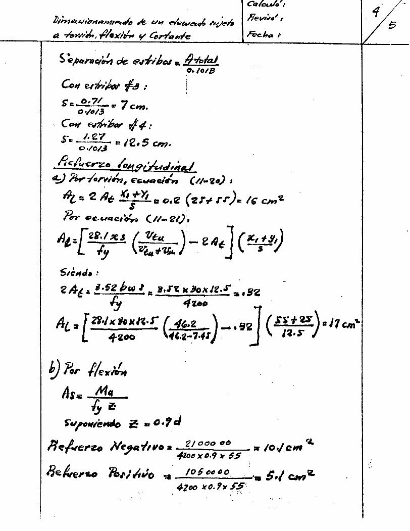
~,n,.,t?u./,'6nRntl~ ~ u, eor'eeu~ ,.~en a ~.,-y4(,, #.xl~ y Ci,,..,tq,,e
Co, e,?,,.¡,.. {-4 .· $r:. o,?/ .., -= ., cm.
C•/()/,3
e (Hf eJ~:6~ vi ti .· r I·'Z7 n S ., ~ -- e: 1 ,. Ch1•
Oo/C/..1
./i~~€r'""Z.o., h~~t'&J~;,...; ~ ~ -/.,.,;.tn 1 E'GA~Qc/h ( //• 'l. t~) 1 .
.9¿, = 2 li.¡; Ki .¡..)í e: o,2 ( 2r~ rr )e /~cm Y. S .
?trr 6"~c.IG1Ct~ (//- ~/)',
At :-.[2e.1 ~ s ( -v~4( ) _ e 4~] (~t., .,. 9, l /y V~ "1&c, _ S '/
s,é,J. : . -
2 A-i A t1 ~sz PtAJ 1 ~ ,.r~ H 8()}( Jt • .r a f B2 o
lj "/tAO o '
A¿ • [ZB" K loMJ".r ( tt/,.2 -) _, 921 ( ~s +u)= J7 cm ... 4f-2.oo 'fC.2-_7·4t . j I~·S"
") ?o,. 1/erl,!,. A-s~ tYit~
(y~ StJ /'•111ellf!Jo &! ar D • '/ J
Rt:.;.,ere. Ne_, • .¡,,o a 2/ oco ~t:J ~ /0·/ C!llf r.¡, ttf.totJ )( IJ,t¡ ~ 5.S
'
/if4~e,-w 11,¡.¡/uJo ~ /05 tJt1 IJO. · ~-S,/ ·CMr¿ 4ZDD JttJ. ?)1 .F~<
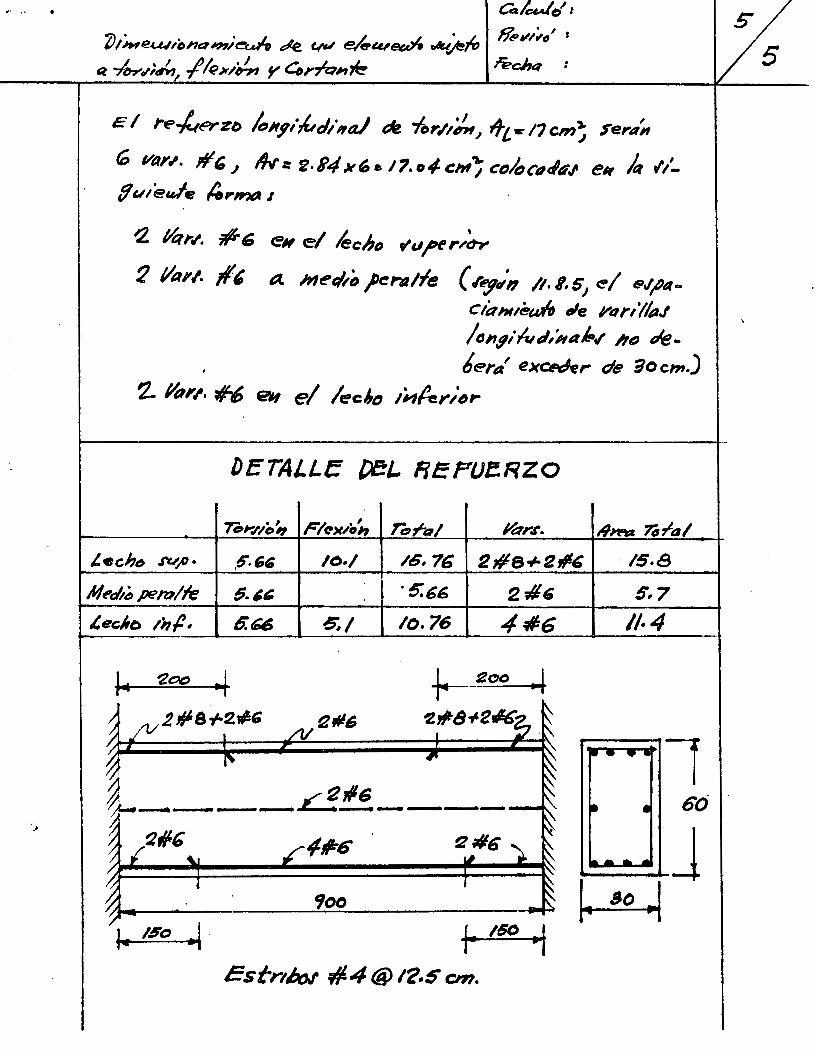
rl~ '. •
~/h'leu.!úJna~??~·~ e:te. ~ e~c:u~ ~)!"" a ~ol;¿, ./lex/~ y 41",1Qh~
Cak..dt/t & ,~;,., 1 1
E 1 re-ker Zb hlf~/tltrJ/,a) ~ -fc,,..,,~, ~l w: 11 cm~ S"ertt',
tó Val'tl. ;¡, J ~ = 2· i4 x(, e 1?. o4- c:M~ cDit:Jct~ri~J e~r k V'l(/u/eule ¡e,W?IA 1
~ t1:tl'tt. #GJ eH el leciJD t'cJ~r,;,.,
2 tia,/. #' a hlet:/~(J 1eralfe ( .r~t/H /1. t, 51 ~1 e.J~a
CÚthlteun Je Vt1,.,'//aJ /tJI'I.filut:l/ha~" 1/t:J "'e-6era' e)(C/Pthr de iO cm.)
~ ¿~p,,, #-6 01 e/ lec~., 1~/er/"~
~------------------------t--
DETAJ.LE {)el- FieFUI!RZO
7C • ' 01'.1'10'1 Flt->t~¡,J, n:,r-a¡ ~,..t'. t9nt::& ?tria 1
/. echt!J ru_,o • ,6'.~G /0·/ /6,76 2#8+2~& ·15-8
Neel!t> pe~/le 5-~~ . 5:61!, 2-4&
l,e~;J,o ti1.P- 6." 6,/ 10.76 4:/1:6
1• /60~. r /60 ~
Estrt/:w' #4@ 1'/.5 cm.
5,7
11·4
r-- .... l ~ •
--·. J ~

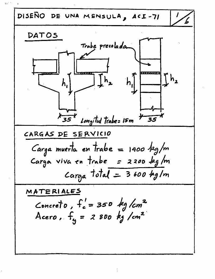
¡.... •
DI~ENO DE VNA ME"'SUL.A 1 Ac.I-71
DATOS
'
~ARGAS PE SE~VICIO
Caraa. mwtr-fQ. e~ trAhe. = I400 ~/m Ctil r» .,_ V 1 V A 't' M .trAbe : .:l :liJ 0 ,¡,. ~ lwa
¿a~a. t o t-.( ~ 3 600 -P-1 /wa
M Ir lE Rl ALE .S
Co11crefo , .f: == 350 )t~ k, a.
Acero, f~ :: ~ BDD ~J /ctt~2..
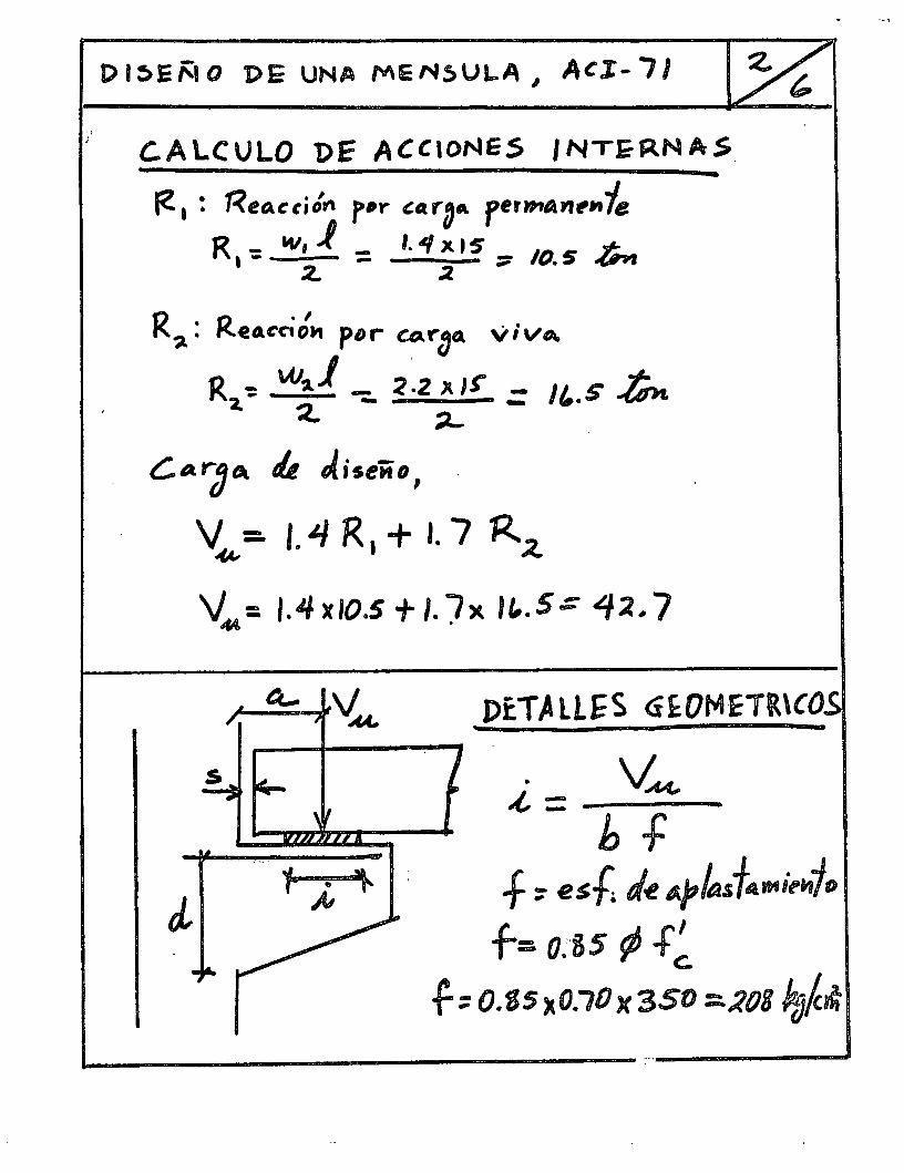
·i
'
t> 1 :)J: ~~O 'DE UNA ME N~UL.A 1 Ac.t- 71
C. A LCULO 'Dr ACCIONES 1 NT~~N AS
te 1 : 'Reo.ccitfl'l f>"Y t:Ar"DA flffi'I/ArlrMie
R ': 'V, J = l. 4 X 15' - Ir' .tP ~ ' 2. .2 - "'· _, Q'P1
R~: Retu:cit., pDr urbo. ViVtA.
R ~ w,_ 1 - 2 .2 x 1 t" - 11 ~ ~ 2.. 2. - ;L. - ... __, -(~H.
C.Argt~t. l.t Jiseiio, .
V~: 1.4 R, + 1. 7 R..-t
V 44 = 1. 4 )( 10.5 + l. J X , , • 5 .:: ~ ~, 7
DETALLES <i~OMETR\CO
. V~ ¿{, = ----bf
.,.. ;., .,_ f ::- e $-h J~ Afias f~trt~i~•i/o
f= 0~85 t/J .f~ f.::O.S5l(O.t0x3SO =-~08 Po~~
~--------------- --.----__.#
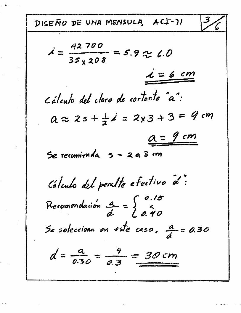
J)l~ENO 'J)i: VNA MENSULA, ~tc.r-)/
. 42. 700 ~ = = S.9 ~t. O
35 X 2..0 8 • _,[, = 6 cm
cé.lcu.lo JJ ckrfJ tJÚ cortnfe "'a.'':
a.~ ;'l S + -}) = :l)l3 ~ 3 ::::: t¡ cW7
t/\.: 9 cm
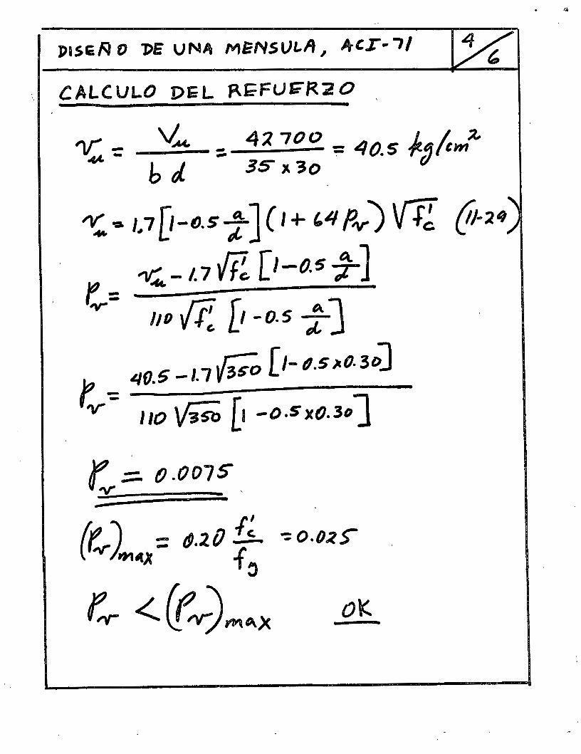
PI SER O l>E UNA Mi?NSt)t..lt, }rCI• "7/ u , CALCULO DEL ~~Fur:::-R20 -
.,... - V.M. - 4;? 700 - 40 L 1 ~ .,.c. - h rJ. - 35" "3o ,.. . 5 f(~tem
~-a 1.1 [1-ttsj-J ( 1 + '4 Pv) Vfi {11-~4~ ~ = -v:.. -l. 1 Re [1-0.5 7] 'V" liD .¡¡;_ D -0.5 ; J
r. ':: 40.5-1.1~ [1-/?.5)10.30]
'V" 110 \li5b [! -o.sxo.l~J
r :::::. (}.007S ~ ' -
. ~
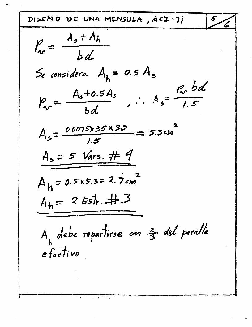
,._ .
e.,.btL /.S
~ '()nsi/trA Ah= 0.5 As
Jo -=- As+o.5A.s . A = r-v bd. . ~ · · s
A _ O.Oo1S~3SX30 _ r-2 z. ~ - - .., . .,., em
J.~
A~;;; S ~t"S. # 4 . 1..
Ah~ 05"Y.S.3= ~. 7eWJ
-Ah::- :? &s1r. ~_3
-Ah J~be rfpaffirse ~ 1- «J JH,.jt
ef.eTivfJ
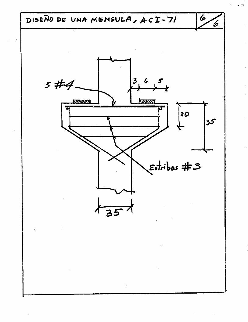
•~ • •'"!
1)15EÑO T>li UNA- /YIEMSULA., A-CI-7/
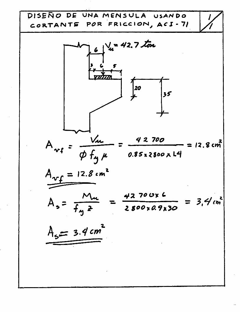
P15EÑO DE UNA MENSULA usANDo c.o~TANTJ8 POR FRlC.CION~ ACl• 7/
v'M-______ = rp f,,.
A-v-¡ = 12.8 , .... ~. -;;: ..
~ A~= .f r
. Aj
A~::= 3.4 cm-z.
--
q 2. 7DD 2. ____ .......,._ : /2. i CWl
o.rs .. ~ soo }\ L~
.¡. ~ 7fJ "~ '
2, 1 D 0 , (). 1/ 1. 30

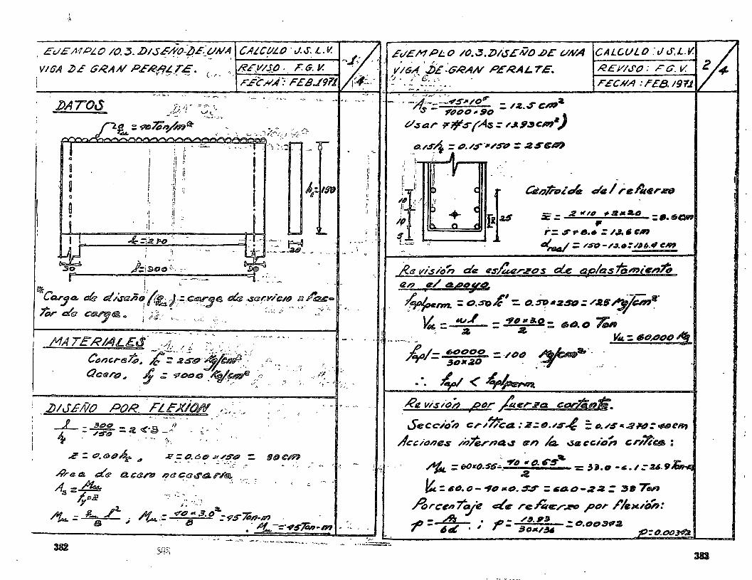
-
-- ,.. ~---- "" "= ~
MA TERIALEtS- :-'J.. / ¿ te' --- - .-"-~ "'-- - -~- - =,
c~nCI'"t!l~~ k;-~SO :&)~.~.-: /~ r; _
C/cqr~" 1 ,: .PODC :~;{~El d,:O " ~ --.:, -<< :: -~-- , .J¡ ' ./ ~~
! .lJIJ'EÑO POR --FLEX)()N r_), _ ;~ •'
- '
,¿< = o, 6)0ñi" di 2 = ¿)_ 6~ P/$'tt# = "' ~ . .: ·.·.;_¡ e
.;9raa .:::(q
A:s :..&r 4pJP t:t can;~ '!'u~aor~ r.l'~ -.~. ,
L. ./a. ,Af--"4 = s ,;
-'<"';: .. _ - -
-.. ,, ... ~-'e: C-
' ;
~ ~ ~ 1 11
--
[
i
-Cstn~~·d,e d'4 1 re/Ji*,.~
;e .:: 2 ~ "' ~ ~,. &o : •· 1601 . , r: S rtJ •• :: I.J. ti eM
dnJ4/ :: /S"t::- /./1. o: .I.U.4' CN?
J€a 1/l.s /o'ñ á~ ~s/:uzrzo s de c!2.olas famien~ ¡
tZn ~/ t2.4~JV9-
~rm.. ;;;50¡{': D. :ir?112Sel.: /.IS .,~~~-14 = ~,/' : OVIJ:. s.q: tb~. O ~
~ .... ~ , a "'-: 16opotJ 1! _Át,/- 6e#DDD : -/l'JtJ
"T' ~DM/lD ;r·-- __ _ . . ~ < 4Jpe¡~
Re v/.s/oá ¡PtJr #er.l'a t:orJtinti.
Secc:-/oñ cr.1~a: 2.:tJ.,-s~ :: "·"~·aN:<118t:W~ Áccione.s /nl'érAa..s an k \Se ccu:1'ñ cr/7;-ca, :
~ .. ~ =t10~t().55.-_ ~IJ ~().~$' : 3J.IJ -.s.I':U.9~
"::61J.()-.,IJ1Ct:J.SS :t;ao-.z~= ~II'TN'I ArC'eni"cy~ ~e re~er..I!!'D p~:~r I'".I!''ÍJñ: 41 - A\- • ~ = /~. I!J - t!J.t:Jt:J3?:1. r - ~,& · ' ' 3D6V~ .-. _,.,. 7V:: (J. DO .:rvA
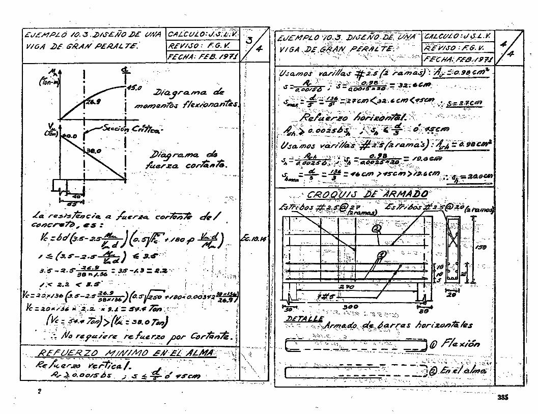
Ec/EHPLd /t/ . .3 . .ZH&S'EÑO J)E VAIA
VIvA .2)E. G'RAH PERALTé.
CALCVLO:.)..';JfJ..-:·v_~ --~-\'-- . ·- d I?Ei//SO: F. G. ~ ;/ 4-
1
FECIIA: FEB. /97f
. 2Jia.~ra.h7a. ~ 1 '""menl'ó.r 1'/ex~D/lanti.s. ..
rSt~~-0~ e,:*~--. • - -- 1 -~ -
'8.0 -. . • · ,., ~-:- · _L 1 .v'-'D;j ra.P'Q. Qf/!1
l'uer za corZint.. .... -; ,_
~ f
á' ~ r, ~ t
.,., ~ ... ~·•.:}
1
,...,)\.:. --··
-..... " -' ~~ _,,_.. <•TI"' ' ~. - "
Et/E M PL O '/0. ~- ./)/JL Nti.'fij:'~i/iv'A-- -CAL CI/L-0 :.e/ eJ. L. Y. ' 1 . . ' ' • :i~~' "'' '"' ' ,.::. -~---' ' -- ' ,- ' -
VIGA . .J)&,G;:¿(1W .PF.RA¿'i":E:i-- ... ilF'YIJ-o :F.G. v. ' ·-:~· -.-\:<.-·-;:- ·"',;:.""-: .. ,~~-·-:-:.: .. ~.,o". FECHA:rE8.</9'F~
. _,_.,... - - ~ ~ - ~ ~
'f!.sa.moJ'·. r~-,.)1/Q...s-' ?¡¡:2~s(:i j-~:Jha'.i)': ::A,;.-5,:0.9~ cm .. · _ &··}· ·-;·.:--....~,--.:l~A1s-·~=---- ~ e _ _ __ · ú-4-DO/S"d ~ ts-aoeu5'~~.:ul;,~-~~--· ~'~- · -·- .. :-: · ; "<. ~::- t:l--:,;J~6 ._,.- . - -/ • - -
.. ú~-- s _ sr ·-;2~-cm........_;sa.·.~cm(.,S:~,·._~-S·=-R·'lCIV'I_
' ' o·~~;~-~:;;~', A~>-~~#~741.· ~-~:·, '. • -'~:, .' • '0 ~_.::·~.' ' -,! :;,_ ' :·-:.. -. ;,--· '":':~-- • ----" --~-----· el ,
,:_ ~,_,·-,, o. tii:J:zsiJ~~-- ,•\:··~ -~'--., :::.~;:-;-u-cm i "',, .. ~ --~· --- -~·-·' '"""~- . -- .......... ....._~~ ............. ~"" ~-J. ~ • • .qi.':
! t/ .sa. ~o.1 ~i:i.r,-í/a·-s>~j¡~s (2 r~;;,~ o/ F?,.;,~= "i.-;a t:m' ' ..;: : .Ak.A .-.. ,,:'e-, - tJ. lB - -~- "- 11{,1:/,S'i; --. ·.r ~ --t:~,~t:nz.S•-20-- /ti.<JCM
--·~ ·>' ~ ·.,_r :;:... ' " - ... ' "· '"'' t'--: :"i:---~. _ t:f(. _ '~" - •r. ',. • ~-- 1c\
i-. -T:_- ~ -.,.~.!"'s-e, >/~or,em.c¡:·""6.":--::ZAti-UI . ' ~-_::::':::.·.~·-·-- ~ .... :: .. "-··"' .. :..':!:-' .
G, 'I#SfJ '
; ~ :.: ¡.; .. .,.1
,_;-,J.,
.... § ..
--- --- > ·- ..... ·- " - ----- '-'"' ... -
385

Vi mtnSIO na.m i~n/Ó CÚ Un e/em-enlo ~ujelA
o. fo,..,;o'n , Ffexi(,.. (j cor 1anfe.
J' 30 ( t
~~~---' ¡.16" V .u.
~= fjJ bd
R<f!fu-triD fr?Jn?$ versJ
tt.) !IJr ~free. qJrf....-J
~= /1,3~
Ve.~bd '11;:: -os VfJ.
Vt + ( '1í;f 11 )'2. ¡,~ 1f4A..
--
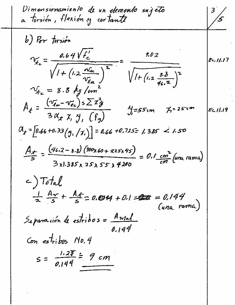
Vim~slnuunílnlo dt un e/im~ s{,lj ¿¡¡, OL -for-5¡¡.. 1 11~/{ j ¡,. 1} ClJI' t-::/J
As-t--::.. 0.1114-f. + O,J ;;4 fJ == (J,/4~ ) (u. n,a_ ~"-.
5.~.;QI'YéA.ci~ IJ. .eslri Lo .s ~ A 1-td_ 0,J44
éc...l/.1'1
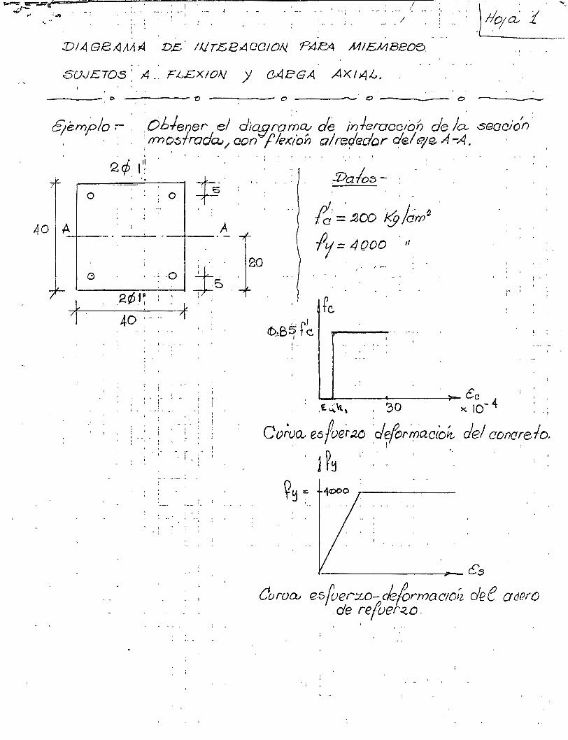
~~~.~~~~. ~~-~---~_-----------: ~:----.-.~~~~~----~------:_~~.~~-~~----~~; J~~ i. ~
..V/4GB-<lt111J4 DL. IIJTEeAOC!ON. P4.eA MIEMBeOS. . . .
SUJETOS' A-· F¿EX!ON j C4PGA AXI~L. '-· ---eo -----v ---- o ____ ,__· o ---~ o -------
E¡émplo ;- :- ;o6-lener el d;?!lro~a: de in feroce/oh de la seacion: . · : ; · rrno~frada.; / con 'f le;cron al rep'edor c(el e¡ e A -A.
' . Q cfi. ¡'~ ..
O ¡O
40 A-1---
1 '
- ¡ _, -' ¡ ¡
- l - - - ~
' .
' f '
: 1
t ~ 1-
l 1
'
• ... r ' ' ~ . - . - - .. '
' ' ' : 1 l 1 ¡ : ' : ' ' (
--- ·-- r.
: - l
' ' 1 ! - :
1
A
- ; ' -¡ - . - -
/Da/o::!>-
f~: , :óOD J9 /dm.~ ly = 4000 'll
' --' - '
~---- ----
~------------~éc ,E. ~'fl, ' 30 X. 10- 4
... '
cv;ua., e6/ver:zo .d~formact'oft. del concrelo. ' ' J ~~ : ._.
~~ ~
t1uroD..J
.. ' 1
•--~~~------~-c3
es(uer:-Lo-de/ormo.c;oíz dee Odf?í() .de re(uer:¿o .
. ,_

l) Ca\cu)o: ck la_ ca.r;3CL a.xio.,t mdx,'ma.; d<2. oompre'ó\O~ : '- -1
'p V = ( b) ( 1;) (o. B 5 f ~) + A '!j ~ j . - ·-- ----- -·-' .
'
~ . ' . ~ - -- - - -- - -.- - - . - . - . 1 • ¡ \ ¡ ;
: = (4o)( 4o) (o. es)( 2ooY-+ ( ~.oq)(4) (4oaq) ~ ~- : ~ : : . --'"
= .2·1 2 SOO + .81) 1 2.0 = 3S 3.J~~D~- ~8·· -~ .. _;
2) CaJcu\o de~ ~~(L aX:ta.J rr0~\m~ de ~eV\S\o~ ·:
Sólo {ra.loa..ta. ·ee..~cero. d~r%üer~o. : · _ .. ·:, ~ .. ?u= (A~) ( f!1) = 4( s.or) (4000): SI) l W
' ' '
?:>) 'ResieAe,Vlef0. ~ óarjet- p.xia.l ·};! ~omeV\+o · f [€1(ioooVI+e c.on uoa... t2KCev")'tr lC\Óo?
1
OUCll'4 Uter(U . . _. . : . . r l - t • : • • • - - •
SupoYi~O ' : : :C.= e,s C'M· :_ ;
o 0o ' · · a..= o.8:s a-.-::; ~.e~)('2.s) = 2 t. 125 c. m.
' - '
: '
, .. . ' ,
- -----
v~ ,
' F~--~----'--· - -..!$ -'
5 ' 0-=21 2S ~e -
' ~~ / c.G.
·'---t--~~ ----
-~
Qj) ·- ' -
t:5[ : ·~-- 1
o 00~ ' o ssf~
\s --
(a.) ; (b) '' -- : (9)
.:De . \o_ ~ {g . , lo.) - . 1
Q.ao~ ~ €..s' · ~ 25 20
e~-= o. ooe4 > o. oo :2; ~ 5. ~~=- 4 oco · K)c 2
o.co3tés =-~ :¡ E~= o.oot2 '( O· 00'2.. ~5 lO
lCl/.:> fl)~f~ OC~lJO..V)te.s SOV1 ~ Ts = A.s ~:> = 2(5.01) ( 2J4oo) = 2 4 4bO ~~. C~==A1~ fs' = -2(6.01-) (4oOO)= -Ll05cóO ~g, Ce=- (O.fOS)(200) (~\.2~)(40) .=-152> 300 \!j
=='/ Pu = Ts +C~ +Ce. = - 10<J) 400 ~g. e e OfflP• ')
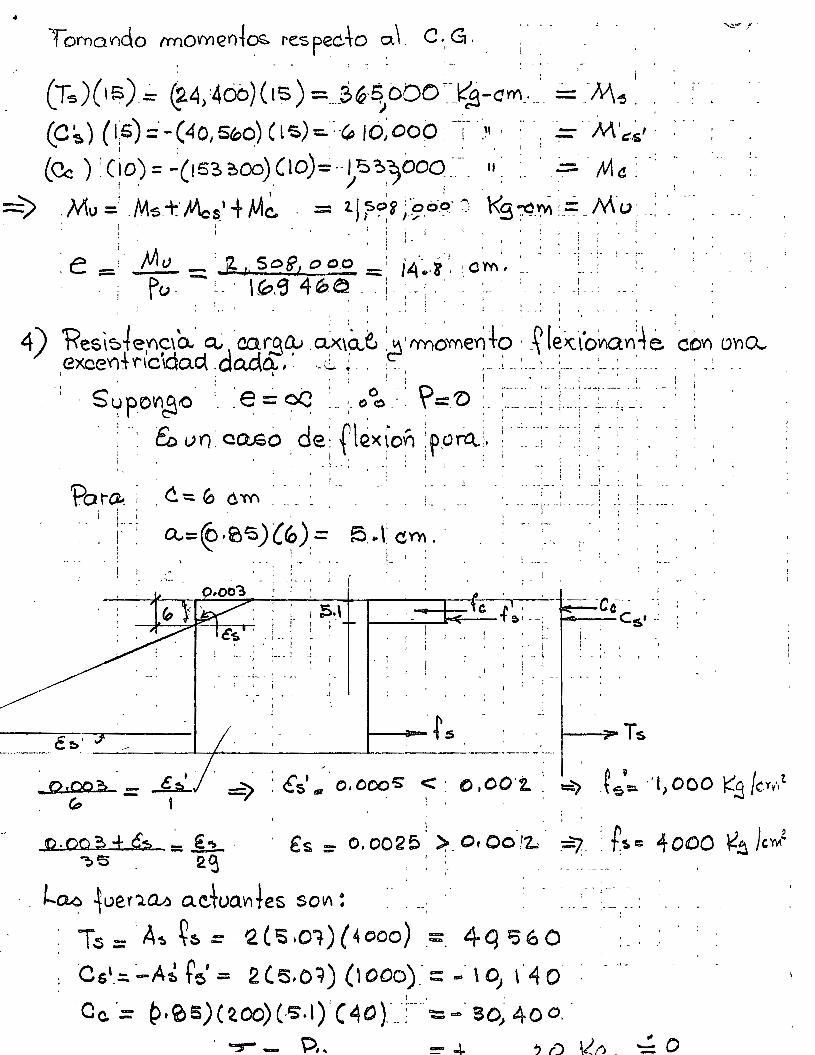
..
i . . .
' -·-ce-·- ., . : Cs• .: i.
1 1 • • 1 ' 1 J t •
.. 1 ! : ·~- ', :- .. -; -: -
1
•- .. ;_ . ; - r-
1 ' 1 : . . - . '
' '
'
. . 1 .
Q,OOp - ~ - (;:, - ' -~ : és'. ·o. ooo'S. e;:= · o ,oo·t ~ =) -~tf3'=- ··1> oc o f(-9 /crv,t 1 '
; .
Q.OO ?> ± é:2 = !~- . ~'5 2<j
. és = o.o02P1
)_Or00-12- -=7-: f~= 40100 ~~}c'r'i· ¡ •
l~ iuer'l~ a.etua"'tes sol/\! . - --- -- --
; j \
Ts:::: 'A~~~=. Q(S.01)(4ooo) .=. 4q ~60 ·es'_=. ~A~ t~' = 2(5,0~) (\OOo)_-:: -· \ D; \.4 o· : C c. . = p ' ~ 5) ( ~ 00) (-S'· l) , ( 4 O ). -.. -:-- .. · = ..... S O) 4 O o . .
. ...,-- P, ..

J
J
J
J
J
J J
J
J
J
J
J
J
J
J
J
J
J
J
J
J
J
J
J
J
J J
J
J
J J
J
J
J
J
J
J
J
J
J
J
J
J
,¡ .. J
J
J
J
J
J
J J
J
' J
J
J
J
J
J
J
J
J
J
J
J
1

- --- ---~----1- ---f---- ¡---- -- ---- r---v-:=~v---rr - f--- -- ---- -----~----- --- -·--- ---- --;-·------- -------- r-· ( J.r2.
.t ¡.-J 1 1 '-~t----:-t-+~1:.i4.JL«j; ~~ flh,;M-~~~~~~-~~~=t-~-f-Ll~1~~xt!U:J.f~=t-i-¡---¡¡¡¡·¡--t-·--+---+--t-- ---- - .. ~ -- - . -+ '. ·, '..11 r ; ~ ' ' ' \. !"
··.:.¡_· --1--l---l---l--t--+--~---t--+--+-+-+--t-t-11~11--1-
·--+--¡---- -- --. - -- ----¡---¡--- - .. --·- --1 -- ---- --·--- --- --.------ ---------..:¡---------·-- ----- ··-- ----.------ ---
, .. ' -V 1~ ' j \ ' t '
------- 3-J -~~ --- --l·--1r--t-- --- --¡----¡----- l- 5-)' t,... -- --~- ---- - ---r--- ---- --- . -- r--- ---
r- \
!ij---+--t--t--t--t--~~~!--+-4~---4~-l~r--1f-l-r-t--r-li+~,¡v~-:-r---¡LJ= --~-.___._~_¡_ -- -- L_l__j__L_L__J__L--l--l~~.l---1----1-~-+--+--+---l-t---t-
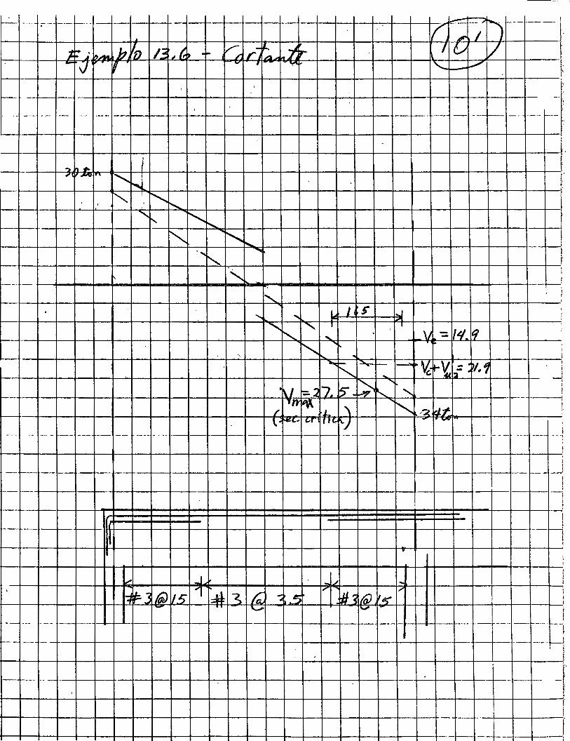
~ -~-- -----1----- ---¡-¡--r--t-+-+-~--+-1--J
- 1 1
-: 1 : i -{
' ! i '
14. Sistemas de piso
1 4. 1 1 nt roducc i ón
Las estructuras de edificios de concreto están formadas por di
versos elementos que generalmente trabajan como un conjunto ya
que dichas estructuras suelen ser continuas o monol iticas. Los
elementos clásicos que constituyen una estructura son las losas,
las trabes y las columnas, aunque en algunas estructuras sólo
existen losas y columnas. Estos elementos han sido estudiados . '
en forma aislada en los capttulos anteriores de este texto. En
este cap1tulo se estudiarán dichos elementos trabajando en con
junto.
Ha sido costumbre anal izar las estructuras, por carga vertical,
suponiendo que 1 as cargas se td:tnsm i ten a 1 as 1 osas, 1 as cua 1 es
las transmiten a las trabes, y éstas, a su vez, las transmiten
a las columnas. O bien, cuando no existen trabes, suponiendo
que las losas transmiten directamente las cargas a las columnas.
Por lo que se refiere a fuerzas horizontales, tales como-fuerzas
de viento o sismo, se supone generalmente que son resistidas por
la estructura formada por trabes y columnas.
En realidad, tanto las cargas verticales como las horizontales
son resistidas por los tres elementos estructurales trabajando
en conjunto. Por ejemplo, en el caso de fuerzas horizontales,
la contribución de las losas es importante; no es posible aislar
las trabes de las losas ya que ambas tra~ajan simultáneamente
bajo la acción de las fuerzas horizontalesa En e1 caso de car-
- 2 -
gas verticales, se ha demostrado que la-distribución de momen
tos flexionantes en las losas depende de la relación de rigi
deces entre losas, trabes y columnas; la distribución de -momen
tos en dos sistemas de piso iguales entre sf resulte diferente
si las columnas de uno de los sistemas son diferentes de las
~lumnas del otro sistema. Esto se debe al distinto grado de
restricción en ambos sistemas de piso.
Por otra parte)ha sido-costumbre considerar como sistemas dife
rentes a los constituidos por losas apoyadas sobre trabes y por
losas apoyadas directamente sobre columnas. Como consecuencia
de esto, los métodos de análisis y diseño de ambos sistemas di
fieren en sus principios. La razón es de origen histórico.
Las losas apoyadas sobre columnas se empezaron a construir antes
de que se conocieran métodos de análisis, sobre una base comple
tamente emptrica. Los métodos.que se han usado hasta la fecha
son, por lo tanto, de naturaleza emptrica. En cambio, las losas
apoyadas sobre trabes se empezaron a construir cuando ya se di~
ponia de métodos matemáticos de análisis. Actualmente, se usan
modificaciones de dichos métodos que toman en cuenta las carac
teristicas especiales del concreto reforzado. Ahora se recono
ce que en realidad los dos sistemas de piso trabajan en la mis
ma forma.
Recientemente se han desarrol·lado métodos de análisis de estru~
turas de concreto que consideran, por una parte,· él 'trabajo en
conjunto de los elementos estructurales, y por otra, el hecho
de que los sistemas de piso act~an en la misma forma cualquie-
- 3 -
ra que sea la rigidez a flexión de las trabes. De esta manera,
cuando las losas están apoyadas sobre muros rigidos, se consi
dera que lo están sobre trabes ~e rigide~ a flexión infinita, y
cuando están apoyadas directamente sobre columnas, se considera
que el sistema de piso tiene trabes de rigidez a flexión nula.
Dentro de estos dos casos ltmite, puede haber trabes de cualquier
rigidez.
14.2 Estudios experimentales de sistemas de piso. Principales
Variables.
Los elementos de concreto reforzado estudiados en capttulos an
teriores han sido elementos isostáticos, en los cuales se han
supuesto conocidas las acciones internas. Los sistemas de piso
son, por el contrario, elementos altamente hiperestáticos en
los que la determinación de tales acciones es un problema com
plejo. En la sección 12.3 se !ndicó cómo pueden determinarse
los momentos flexionantes en losas aisladas apoyadas sobre el~
mentes infinitamente rfgidos. Sin embargo, la distribución de
momentos flexionantes en sistemas de 'piso depende, no solamen
te de las caractertsticas propias de la losa, sino también de
los otros elementos que constituyen la estructura, como las trg
bes y las columnas. La distribución de momentos es importante,
porque, en general, es necesario conocer dichos momentos para ~
diseñar los aementos estructurales. Por esta razón» se ha es
tudiado dicha distribución tanto en forma experimental como
analftica.
- 4 -
El número de ensayes real izados· en estructuras formadas por
losas, trabes y columnas es escaso. La serie más extensa es
la realizada en la Universidad de 111inois 14• 1- 14•6
entre
lo~ afios 1960 y 1963, que incluyó el ensaye de especrmenes
como el mostrado esquemáticamente en la Fig. 14.1. Los
resultados de estos ensayes, en combinación con estudios an~
1 fticos, han permitido desarrollar métodos de diseño que _toman
en cuenta el efecto de las variables más importantes sobre el
compotamiento de las estructuras.
Para estudiar la distribución de momentos flexionantes, consl
dérese que en la estructura mostrada en la Fig. 14.2, se ais
la la franja de losa comprendida entre los ejes A' y B'. Si
se supone que los momentos flexionantes son uniformes a lo an
cho de la franja resultante, puede considerarse a esta franja
como una viga contfnua con una distribución de momentos flexiQ
nantes como la mostrada en la"Fig. 14.3 en forma cualitativa.
Si la losa tiene una carga uniformemente distribufda, ~, la
viga continua de la Fig. 14.3 tiene una carga por unidad de
longitud de un valor wf2, donde~2 es el ancho d~ la franja
entre los ejes A' y B'. En cada uno de los claros de la viga
continua, se debe cumplir la siguiente ecuación de equilibrio.
(14.1)
donde:
M0
=Momento estático total·= Momento positivo en el centro del
claro, más_el promedio de los momentos negativos en los
extremos.
\
- 5 -
wi2 = Carga por unidad de longitud
~ 1 =Longitud del claro considerado
Por ejemplo, en el claro 2-3:
Mo = M(-)2 +M(-}3+ M(+} 2
(14.2}
En realidad, los momentos flexionantes no son uniformes a lo
ancho de la franja considerada en la Fig. 14.2. A lo largo
del eje de columnas, B~ los momentos son mayores que a lo laL
go de los ejes A1 y 81• Esto se debe a que el sistema es más
rfgido a lo largo del eje B por la presencia de vigas y porque
el efecto de restricción de las columnas es máximo en estos
ejes y va disminuyendo hacia los extremos de la franja.
La distribución cuantitativa de momentos a lo largo y a loan
cho de las franjas de losa depende de las caracterfsticas de
los elementos que forman la estructura (columnas, vigas y lo
sas) y del tipo de carga aplicada. En las siguientes secciones
se describe la influencia de estas variables.
14.2.1 Influencia de las columnas
Las columnas influyen sobre la distribución· de momentos en la
losa por la restricción que ejercen sobre las vigas y la losa,
o sea, por el empotramiento parcial que proporcionan a estos
elementos estructurales.
Considérese nuevamente la distribución de momentos a lo largo
de la franja A1 - 8 1 mostrada en la Fig. 14.3. Si la rigidez
f1exionante de las columnas es grande en comparación con la ri-
gidez flexionante de vigas y losa, la restricción de las colum-
- l

- 6 -
nas en Jos extremos de la viga continua es grande y Jos mamen
tos flexionantes en estos extremos son relativamente grandes*.
En cambio, si la rigidez flexionante de las columnas es peque
ña en comparación con la de vigas y tosa, la restricción y tos
momentos flexionantes en los extremos también son pequeños. En
la Fig. 14.4 se comparan cualitativamente estos casos: la Fig.
14.4-a corresponde al primer caso mencionado y la Fig. 14.4~b,
al segundo caso. Teóricamente, si la rigidez flexionante de
las columnas es nula, los momentos en Jos extremos de la viga
continua son nulos. Este caso, que se muestra en la Fig.
14.4-c, puede presentarse cuando las columnas no son mono] fti
cas ni están unidas rfgidamente a las vigas y a la losa.
La rigidez flexionante de las columnas influye también sobre
el valor de los momentos ftexionantes en otras secciones de la
viga conttnua de la Fig. 14.3. Los momentos positivos en Jos
claros extremos (1-2 y 3-4) son mayores mientras menores sean
Jos momentos en Jos extremos de la viga continua. Por Jo tan
to, son mayores mientras menor sea la rigidez flexionante de
las columnas. Esto s~ debe a que la Ec. 14.2 debe cumplirse
por condiciones de equilibrio, y al disminuir uno de los mamen
tos negativos necesariamente debe aumentar el momento positivo,
ya que el momento estático total permanece constante. La in
fluencia de la rigidez flexionante de l~columrtas sobre los
momentos negativos y positivos en claros interiores, como el
claro 2-3 de la Fig. 14.3, es menor que sobre los momentos de
*Se supone en este capitulo, que el lector está familiarizado
con el análisis elemental de estructuras hiperestáticas.
- 7 -
los claros extremos, siempre que la carga de la losa esté
uniformemente distribufda enmdos los claros. Cuando la
carga no está uniformemente distribufda en todos los claros,
la influencia de la rigidez flexionante de las columnas es
también importante sobre los momentos en claros interiores. '
Este caso se anal izará en la Sec. 14.2.4, que trata del efecto
del tipo de carga.
14.2.2 Efecto de la rigidez flexionante de las vigas
La rigidez flexionante de las vigas, comparada con la rigidez
flexionante de la ~osa, influye en la distribución de momentos
a lo ancho de la franja. Si las vigas· son de peralte grande
en comparación con el peralte de la losa,. un gran porcentaje
del momento total en una sección transversal es resistido por
las vigas y un porcentaje pequeño por la losa. En losas pla
nas, en las que no existen vigas, todo el momento es resistí-. do por la losa. Dentro de estos dos casos, el peralte de la
viga puede ser de cualquier valor y el momento total se distrl Iet.
buye entre la viga yAlosa de acuerdo con su rigidez flexionan-
te.
14.2.3 Efecto de la rigidez torsionante de las vigas
La rigidez torsionante de las vigas proporciona~un empotramien
to parcial a las losas. Su efecto es especialmente importante
en los bordes del sistema de piso, y en tableros interiores
cuando un tablero se encuentra cargado y el tablero adyacente
descargado. En el primer casop aumentan los momentos negativos
- 8 -
en la losa mientras mayor sea la rigidez torsionante. El se
gundo caso se anal iza al estudiar el efecto del tipo de carga
(Secc. 14.2.4).
Para que en un sistema de piso exista el efecto de la rigidez
torsionante de las vigas, es necesario que éstas sean monol ftl
cas con la losa y con las columnas. Si no se cumple la prime
ra condición, las vi~as no pueden restringir o empotrar a la
losa, y no pueden desarrollarse momentos flexionantes en la lo
sa en los bordes del sistema de piso. Si la viga no es monoll
tica con las columnas, no pueden desarrollarse en ella momentos
torsionantes pues girarfa 1 ibremente en sus extremos.
14.2.4 Influencia del tipo de carga
En un sistema de piso, no necesariamente se encuentran cargados
siempre todos los tableros. Es frecuente, por ejemplo, en el
caso de bodegas, que algunos tableros soporten carga viva y otros
no.
Asf como en vigas continuas existen combinacion~s de carga con
las cuales los momentos en ciertas secciones son mayores que
los correspondientes a carga unifo~me en todos los claros de la
viga, también en sistemas de piso existen combinaciones desfavo
rables de carga. S in embargo, la carga muerta, ,.que siempre es . '
considerable en sistemas de piso, actúa uniformemente en todos
los tableros. El incremento de momentos, respecto a Jos prodg
cidos por carga uniforme en todos los tableros, depende de la
relación de carga viva a carga muerta. Mientras mayor sea esta
relación, mayor es el incremento. En la Fig. 14.5 se presentan
- 9 -
combinaciones de carga con las cuales se obtienen momentos
po5itivos y negativos m§ximos.
El efecto de combinaciones desfavorables de carga está relaciQ
nado en f~rma importante con la rigidez flexionante de las co
lumnas y con la rigidez torsionante de las vigas. Un incremen
to de estas rigideces aumenta el empotramiento de un tablero
de losa dado y por consiguiente este tablero es menos sensible
a las condiciones de carga de tableros vecinos.
14.2.5 Comentarios sobre los efectos de las variables
En los párrafos anteriores se han se"alado las principales
variables que influyen en el comportamiento de sistemas de piso,
sin incluir los efectos de las propiedades de los materiales,
como resistencia del concretog porcentaje de refuerzo y 1 tmite
de fluencla del acero, ni el efecto de la forma de las losas.
Se ve que el número de variaoles es considerable y que el efec
to de algunas está relacionada con el efecto de otras;por ejem
plo, el efecto del tipo de carga está relacionado con el efecto
de las rigideces de columnas y trabes. Esto hace que el trata
miento riguroso de los sistemas de piso sea un problema muy com
plejo y que sea necesario recurrir a procedimientos simplifica
dos que tomen en cuentaJ~manera aproximada el efecto de las
principales variables.
También se deduce del estudio de las variables, que en general
no es suficiente considerar a la losa como un elemento aislado,
sino que es necesario tomar en cuenta su interacción con los
otros elementos estructurales para estudiar adecuadamente su
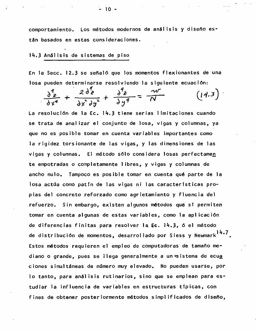
- 1 o -
comportamiento. Los métodos modernos de análisis y diseño es
tán basados en estas consideraciones.
14.3 Análisis de sistemas de piso
En la Secc. 12.3 se señaló que los momentos flexionantes de una
losa pueden determinarse resolviendo la siguiente ecuación: l
2d~ d~& o "".r ;ver Q_4,3) + ·:a.+ - N -
d -¡.4 d~"&. Jv J ~1 La resolución de la Ec. 14.3 tiene serias 1 imitaciones cuando
se trata de anal izar el conjunto de losa, vigas y columnas, ya
que no es posible tomar en cuenta variables importantes como
la rigidez torsionante de las vigas, y las dimensiones de las
vigas y columnas. El método sólo considera losas perfectamen
te empotradas o completamente 1 ibres, y vigas y columnas de
ancho nulo. Tampoco es posible tomar en cuenta qué parte de la
losa act~a como pattn de las vigas ni las caracterfsticas pro
pias del concreto reforzado como agrietamiento y fluencia del
refuerzo. Sin embargo, existen algunos mé~odos que sf permiten
tomar en cuenta algunas de estas variables, como la aplicación
de diferencias finitas para resolver la Ec. 14.3, 6 el método
de distribución de momentos, desarrollado por Siess y Newmark14•7•
Estos métodos requieren el empleo de computadoras de tamaño me
diano o grande, pues se llega generalmente a un~istema de ecu~
ciones simultáneas de namero muy elevado. No pueden usarse, por
lo tanto, para análisis rutinarios, sino que se emplean para es
tudiar la influencia de variables en estructuras ttpicas, con
fines de obtener posteriormente métodos simp1 ificados de diseño,
- 1 1 -
y para comparar los resultados experimentales con resultados
anal Tticos y deducir de ahf la influencia del tipo de material.
Los métodos de análisis mencionados anteriormente se han usado
para determinar la distribución de momentos flexionantes en e~
tructuras del tipo mostrado en la Figo 14ol y estas distribuciQ
nes se han comparado con las obtenidas en ensayes 14.8.
La concordancia entre momentos analTticos y experimentales es
buena, en general, por lo cual se han podido desarrollar méto
dos de diseño a partir de análisis teóricos. Ha quedado demo~
trado que los resultados de análisis de losas ideales de material
elástico, homog~neo e isotrópico, son ,aplicables a losas de con
creto reforzado, si se hacen ciertas modificaciones indicadas
por los resultados experimentaleso Las modificaciones más im
portantes consisten en tomar en cuenta que el efecto de cargas
parciales es menos importante.en estructuras de concreto refor
zado que en estructuras ideales, y que los momentos negativos
en estructuras reales son 1 igeramente menores que en estructuras
ideales y los positivos son 1 igeramente mayores.
Esto último puede deberse a que la losa se agrieta en las zonas
de momento negativo antes que en las zonas de momento positivo,
por ser mayores los momentos negativos, y como consecuencia ~ o' los momentos se redistribuyen de las zonas de momento negat1vo
a las zonas de momento positivoo
14.4 Dimensionamiento de sistemas de piso
El método que se presenta a continuación para el dimensionamien

- 12 -
to de sistemas de piso se conoce con el nombre de método de
la estructura equivalente, debido a que se basa en el prin
.cipio de sustituir a la estructura tridimensional, constitul
da por el sistema de pfso, por un marco bidimensional equlvg
lente, constituido por columnas y trabes. El método es siml
lar al presentado en el Reglamento ACI 1941 y ediciones si--
guientes, pero con modificaciones que 'Se le han hecho parn
. 1 1 1 d 1 b .d 14.9 y 10 ajustar os momentos ca cu a os a os o ten1 os en ensayes.
El método consiste en los pasos que se mencionan a continua
ción en forma resumida y que se describen con detalle más
adelante.
a) Idealización de la estructura tridimensional en marcos
bidimensionales constituidos por columnas y trabes.
b) Determinación de' 1 as rigideces de 1 os e 1 ementos que
forman los marcos.
e) Análisis estructural de los marcos.
d) Distribución de los momentos flexionantes y fuerzas COL
tantes obtenidos en el análisis entre 'Jos elementos que
forman la estructura tridimensional.
e) Dimensionamiento de los elementos de" la estructura.
14.4.1 Idealización de la estructura
- 13 -
En el método de la estructura equivalente se hace una simpl ifl
cación que consiste en ideal izar 1~ estructu~a por una serie
de marcos en dos direcciones, como los que se muestran en las
. ~rea~ rayadas de la Fig. 14.6 •
Las columnas~de bs marcos equivalentes son iguales a las co
lumnas de la estructura modificadas de tal manera que, además
de la columna propiamente dicha, incluyen a la trabe perpendl
cular a la dirección del marco equivalente, como se muestra en
la Fig. 14.7. Esta modificación se hace para tomar en cuenta
el efecto de restricción por torsión que ejercen las trabes
sobre la losa (Sec. 14.2.3)o En, sistemas de piso sin trabes,
se supone que existe una trabe cuyo peralte es igual al de la
losa y cuyo ancho es igual al de la columna, capitel o ábaco
en la dirección del marco equivalente. En sistemas de piso
con trabes, ·se supone que las trabes transversales, son tra
bes T o L cuyo ancho del patfn es igual a la proyección de la
trabe por arriba o por abajo de la losa, pero no mayor que
cuatro veces el espesor de la losa.
En Al caso de Josas apoyadas sobre vigas, las trabes de los V
marcos equivalentes están formadas por las vigas de la estruc
tura y los tramos de losa comprendidos entre los ejes centra
les de los tableros; las vi~as y la losa en conjunto constity
yen una trábe equivalente cuyas caracterfsticas se definen co
mo se indica en la Sec. 14.4.2. En el caso de Josas apoyadas
- 14 -
sobre columnas, las trabe~ de los marcos están formadas por
los tramos de losa comprendidos entre los ejes centrales de
los tableros. La manera de transformar los tramos de losa
en trabes equivalentes se Indica también en la Secc. 14.4.2.
14.4.2 Determinación de las rigideces de los elementos
Para calcular las rigideces se consideranúnicamente seccio-
nes gruesas de concreto sin agrietar y sin tomar en cuenta
el acero de refuerzo. A continuación se presentan por sepa
rado los métodos de cálculo de rigideces de trabes y columnas
en sistemas de piso sin trabes y con trabes. Se presenta
únicamente la forma de calcular los valores de 1/EI, ya que
a partir de estos valores pueden calcularse las rigideces 1
tomando en cuenta las longitudes de los claros y las condiciQ
nes de restricción en los extremos de columnas y trabes. En ~ todos 1 os ca sos, e 1 va 1 or de E es e 1 de 1 ~f t » de e 1 as ti e i-
dad del concreto, Ec.
a) Trabes del marco equivalente en sistemas de piso s'in vigas
El caso_. más general de estos sistemas se muestra en la
Fig. 14.8-a, la cual representa un sistema que incl~ye lo
sas, ábaco y capitel.
El momento de inlPrcia de la sección A-A es el de una sec
ción rectangular.
El de la sección B-B, se calcula como el de la sección T
mostrada en la Fig. 14.8-c.
La sección CC mostrada en la Fig. 14.8-d es de peralte
variable; sin embargo por simplicidad se supone que el
momento de·inercia1 del eje de la columna al extremo del
- 15 -
capite~ es constante~ e igual al momento de inercia~n la 2
sección del ábaco dividido entre el factor (1-cz/lz) , don-
de c 2 y 12 son las dimensiones del capitel y del claro en
dirección transversal a la del marco equivalente considera-
do. La distribución de valores de 1/EI a lo largo del cla
ro se muestra en la Fig. 14.8-~. En las Tablas 14.1-y 14.2
se presentan constantes de distribución de momentos calcug.Mj-e;-ror€
ladQS con los criterios para placas planas y losas planas
sin capiteles.
b) Trabes del marco equivalente en sistemas de piso con vigas
En estos sistemas el valor de EI es constante en todo el
claro. El valor deJ: se calcula sumando el momento de ineL
cia de una trabe T y el de una sección rectangular, como se
muestra en la Fig. 14.9. Los patines de la trabe T tienen
un ancho igual a la proyección del alma de trabe por arriba .
o por abajo de los patines, sin exceder cuatro veces el es-
pesor de la losa, y el ancho de la sección rectangular es
igual al ancho promedio de los claros transversales, 12 ,
menos el ancho del patfn de la trabe T.
e) Columnas del marco equivalente
Se mencionó anteriormente que 1a columna equivalente está
formada por la columna y una trabe que trabaja~a toraión
restringiendo a la losa, Fig. 14.7. Para calcular la ri-
gidez de este elemento compuesto, se parte de la hipótesis
de que su flexibilidad, o sea, el recfproco de su rigidez, \
es igual a la suma de las flexibilidades a flexión de los
- 16 -
tramos de columna y por arriba y por abajo del nivel de
piso y de la flexibilidad a torsión de la trabe. Esta
consideración, obtenida con base en los ensayes mencion~
dos anteriormente, puede expresarse mediante la siguiente
ecuación:
1 -- + (14.4)
donde
Kec = rigidez de la columna equivalente, en momento por
unidad de rotación.
:E Kc = suma de las rigideces a flexión de los tramos de
columna comprendidos entre el nivel de piso consi
derado y los niveles superior e inferior.
Kt = rigidez a torsión de la trabe •
. Para calcular la rigidez K de cada columna, se supone que el
e valor de 1 es constante e igual al de la sección gruesa de ca
da columna entre la cara superior de la losa y la base del e~
pitel del nivel superior, que 1 es infinito a lo alto de la 12
sa, y~rfa 1 inealmen.te entre los dos valores anteriores a lo
" alto del capitel. En la Fig. 14.10 se presenta la variación
en los valores de 1/EI de una columna de acuerdo con los cri-S!.'
terios anteriores. Para calcular las rigide,ese considera
que la altura de las columnas se mide centro~ centro de las
losas, como se muestra en la Fig. 14.10 •
.S La rigidez tor~ionante, Kt, de la trabe unida a la columna,
Fig. 14.7, puede calcularse con la siguiente ecuación14.10 ~
- 17 -
( 14. 5)
donde
Ecs = módulo de elasticidad del concreto de la losa
c::::E(l-Oo63 ~)x;y (14.6)
x =dimensión total menor de una sección transver-
sal rectangular
y =dimensión total mayor de una sección transver
sal rectangular
La suma que aparece en la ecuación 14.6 se refiere a los rec
tángulos en que puede descomponerse la sección T o L de la
trabe de la Fig. 14o7
A partir de los valores de Kc y Kt se calcula la rigidez de
la columna equivalente, K , con la ecuación 14.4. ec
14.4.3 Análisis estructural de los marcos
Una vez calculadas las rigideces de las trabes y columnas de
la estructura equivalente, se efectúa el análisis estructural
por los procedimientos usuales para marcos bidimensionales, El
análisis por carga vertical puede efectuarse aislando 'Cada uno
de los pisos y suponiendo que las columnas de los entrepisos
superior e inferior están empotradas en sus eXtremos opuestos.
En el análisis por carga horizontal (viento o sis~o) deben
considerarsé los marcos completos.
Cuando la intensidad de la carga viva no excede de las tres cuaL
tas partes de la intensidad de la carga muerta, o cuando todos
los tableros de la losa se encuentran cargados simultáneamente J
- 18 -
el análisis estructural se efectúa suponiendo que todos los
tableros están cargados. Cuando no se cumplen estas condi
ciones, el momento pos~ivo máximo en un claro dado se cale~
la suponiendo que el claro está cargado con las tres cuar
tas partes de la carga viva y con la carga muerta total, y
que los claros adyacentes están cargados únicamente con la
carga muerta. El momento negativo máximo en un nudo dado
se calcula suponiendo que los dos claros adyacentes al nudo
están cargados con las tres cuartas partes de la carga viva
total, y Jos claros siguientes están descargados. En la
Fig. 14.11 se ilustra las condiciones desfavorables de car
ga descritas anteriormente y la simplificación de la estru~ • tura que puede hacerse para efectos de cálculo por carga
vertical.
En nudos interiores, la sección crftica por momento negati
vo esti local izada en las ca~as de las columnas, pero a una
distancia no mayor de 0.1751, del centrode la columna. En
apoyos exteriores con capitele~, la sección crttica por mo
mento negativo está local izada a la mitad de la distancia
entre la cara de la columna y el extremo del capitel. La
sección crttica por momento positivo se considera siempre
al centro del claro.
14.4.4 Distribución de momentos flexionantes y fuerzas cortantes
Los momentos flexionantes y fuerzas cortantes obtenidos median
te el análisis descrito en la sección anterior corresponden
a las trabes y columnas del marco equivalente. Es necesario
- 19 -
distribuir estos momentos y fuerzas cortantes entre los ele
mentos del sistema de piso.
Puesto que las trabes del marco equivalente representan a
las franjas del sistema de piso mostradas en la Flg. 14.6,
los momentos y cortantes deben distribuirse entre los ele
mentos comprendidos en dichas franjas. Para hacer esta di~
tribución, la franja de piso se divide en una franja de co
lumna y una o dos medias franjas centrales, como se indica
en la Fig. 14.12. La franja de columnas incluye-las vigas, en
caso de que existan.
Una vez hecha la división en franjas señalada anteriormente,
se distribuyen los momentos obtenidos en el análisis estruc
tural entre la franja de columnas y las franjas centrales de
la manera siguiente. Se calculan los momentos e~ las franjas
de columnas multiplicando los momentos por los porcentajes . mostrados en la tabla 14~. Después se distribuyen los mo-
mentes de las franjas de columna entre las vigas, si existen,
y los tramos de losa, de acuerdo con lo que se indica en la
tabla 14.~; si no existen vigas, todo el momento de las fran
jas de columnas es resistido por la losa. Por último, se cal
culan los momentos en las franjas centrales restando los mo
mentos de las franjas de columnas de los momentos totales. \'
La distribución de .momentos en las tablas 143 y 14.4está
hecha en base a la relación de claros (1 211 1) y a factores que
involucran las rigideces a flexión de trabes y losas y la rigl
dez a torsión de las trabes de borde.
- 20 -1
Se ha visto anteriormente que estos parámetros son los que
más inf~luyen en el comportamiento de sistemas de piso. Los d, {J~
factores - - que aparecen en las tablas se definen
de la siguiente manera:
~~=relación entre la rigidez a flexión de la sección de
la viga y la rigidez a flexión de los tramos de losa
de la franja de columnas. La viga debe considerarse
de sección T o L, como se muestra en la Fig. 14.9.
Puede expresarse como ( Ecb.l b/Ecs 1 s) , donde Ecb es e 1
módulo de elasticidad del concreto de la viga; lb ,
el· momento de inercia~de la viga; Ecs , el módulo de
elasticidad del concreto de la losa; ls , el momento
de inercia de la losa.
~ t = relación entre la rigidez a torsión de la sección tran~ versal de la viga de borde y la rigidez a flexión de
El
un tramo de losa cuy.o ancho es igual al claro centro a
centro de apoyos de la viga de borde. Se expresa co-
mo (EcbC/2Ecsls). El término C se define en la ec. 14.6
y los otros términos ya han sido también definidos.
Í~lJs se hace de la
"""'""'~._,;;,.; es i gua 1 o manera.
mayor que 1 .O, se calcula a partir de áreas tributarias de lQ
sa del imitadas por lfneas a 45• trazadas a partir de las es
quinas de los tableros y por lfneas para'lelas a los lados laL ·O...
gos de los tableros. Cuando ~ 1 es igual~cero, se supone que
las vigas no reciben carga. Para valores intermedios de~ 1
- 21 -
se interpreta 1 inealmente.
Los momentos flexionantes de diseño en las columnas son los
mismos que los obtenidos en las columnas equivalentes • . .1.(
~~~
Las trabes de la estructura, especialmente las de borde, ajo la acción de momentos
torsionantes debidos a la restricción que proporcionan a las losas. Estos momentos
pueden calcularse distribuyendo los momentos de las columnas equivalentes entre
las columnas y las trabes, Fig. 14.7, proporcionalmente a sus rigideces Kc y Kt.
Obsérvese que el momento en las columnas es el momento total en las columnas
equivalentes, ya que los momentos torsionantes en las trabes9e transmiten a las colum-
nas como momentos flexionantes.
14.4.5 Dimensionamiento de los elementos de estructura.
Una vez obtenidas las acciones internas (momentos flexionantes, fuerzas cortantes
y momentos torsionantes) en los miembros estructurales, se procede al dimensiona-
miento de los mismos siguiendo los métddos descritos en capítulos anteriores de este
texto. En el caso de losas apoyadas directamente sobre columnas y sujetas a cargas
horizontales, debe considerarse el problema de la transmisión de momento flexionante
de la losa a la columna. Para que el comportamiento de la estructura sea más eficiente
a este respecto, se recomienda concent~ar el refuermo de flesión necesario para
resistir las fuerzas horizontales en una franja de losa localizada sobre el eje de co-
lumnas y cuyo ancho sea igual al ancho de la columna más el gr9sor de la losa. Deben
revisarse los esfuerzos cortantes por penetración tomando en cuenta las cargas verticales
y los momentos producidos por las fuerzas horizontales.
REFERENCIAS:
14.1 Hatcher, D. S.; Sozen, M. A.;~ Siess, C. P., "Testofa Reinforced Concrete Flat
Plate," Proceedings, ASCE, V. 91, ST5, Oct. 1965, pp. 205-231.
14.2 Guralnick, S. A., ~ Fraugh, R. W ., "Laboratory Study of a Forty-Five-Foot
Square Flat Plate Structure," ACI Joumal, Proceedings V. 60, No. 9, Sept. 1963,
pp • 11 07- 1185 .
14.3 Hatcher, D. S.; Sozen, M. A.; ~Siess, C. P., "Testofa Reinforced Concrete Flat
Slab," Proceedings, ASCE, V. 95, ST6, Jun. 1969, pp. 1051-1072.
14.4 Jirsa, J. O.; Sozen, M. A.;~ Siess, C. P., "Test of a Flat Slab Reinforced with
Welded Wire Fabric," Proceedings, ASCE, V. 92, ST3, Jun. 1966, pp. 199-224.
14.5 Gamble, W. l.; Sozen, M. A.;~ Siess, C. P., "Test of a Two-Way Reinforced
Floor Slab," Proceedings, ASCE, V. 95, ST6 Jun. 1969, pp. 1073-1096.
14.6 Vanderbilt, M. D.; Sozen, M. A.;~ Siess, C. P., "Tests of a Modified Reinforced
' Concrete Two-Way Slab," Proceedings 1 ASGE 1 V. 95,,ST6, Jun. 1969, pp.
1
1097-1116.
14.7 C. P. Siess y N. M. Newmark 1 "Rational Analysis and Design ofTwo-Way Concrete
Slabs" 1 ACI Joumal, Abril, 1950.
14.8 "Measured~eoretical Bending Moments in Reinforced Concrete Floor Slabs," Civil
Engineering Studies 1 Structural Research Series No. 2461 University of lllinois,
Jun. 1962
14.9 Corley, W. G.; Sozen 1 M. A.; y Siess, C. P., "The Equivalent-Frame Analysis for
Reinforced Concrete Slabs 1 " Civil Engineering Studies, Structural Research Series
No. 218, University of lllinois 1 Jun. 1961.
14.10 Corley, W. G. 1 y Jirsa,, J. O., "Equivalent Frame Analysis for Slab Design, 11 ACI
Journal, ProceedingsV. 67,No. 11, Nov. 1970, pp. 875-884.
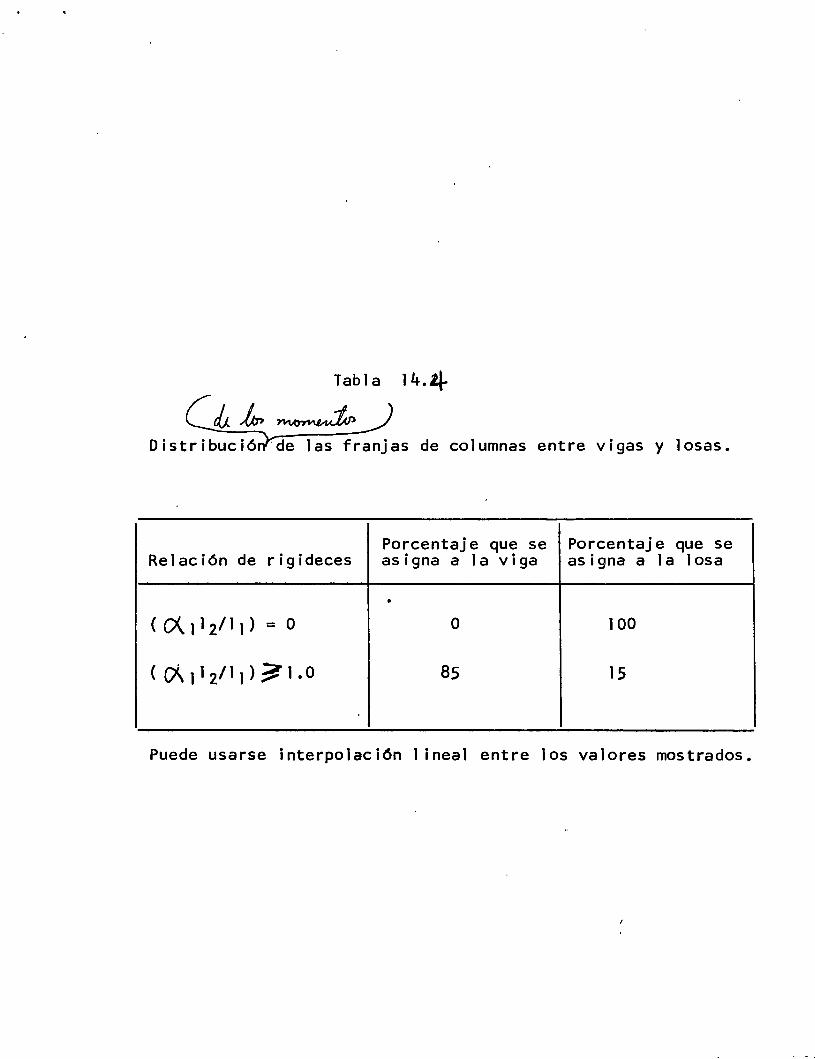
Tabla 14.4
Distribució 'de las franjas de columnas entre vigas y losas.
Porcentaje que se Porcentaje que se Relación de rigideces asigna a la viga asigna a la losa
•
( 0\ ¡1 2/11 ) = o o 100
( C/Í\ ¡1 2/11 ) ? 1. o 85 15
Puede usarse interpolación 1 ineal entre los valores mostrados.
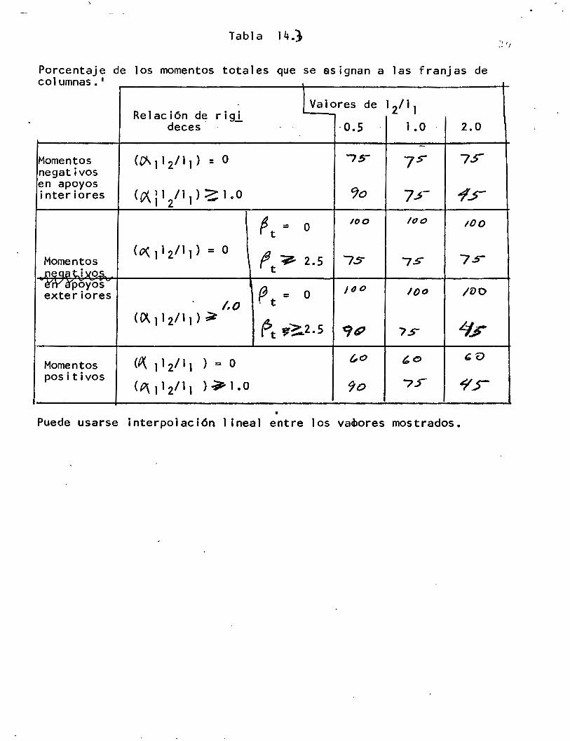
Tabla 14.} :~ 11
Porcentaje de los momentos totales que se asignan a las franjas de 1 1 co umnas.
Relación de rigl Valores de 1211 1
de ces -0.5 1.0 2.0
Momentos (O\ 11 2/ 11 ) = o '75"" 7s- 7.5" negativos en apoyos
(i?\112/11) ~ 1.0 '1o 7~- "'/.F interiores
~ t = o lOO /00 lOO
(0\1 12111) = o ft9 Momentos 2.5 75 7S 7.s-
neaati~os. · é'"rY a"poyos
(J = o J tJ o lOO /DO exteriores t .. o - t
(Ol.ll2/11}~ ~t ~~2.5 '91? L:J; 7.>
(~ 11 2/ 11 ) = o (,o 'o bu Momentos positivos
(P\1 12/ 11 ) ? 1.0 'Jo 7.> "YF
• Puede usarse interpolación 1 ineal entre los va~ores mostrados.
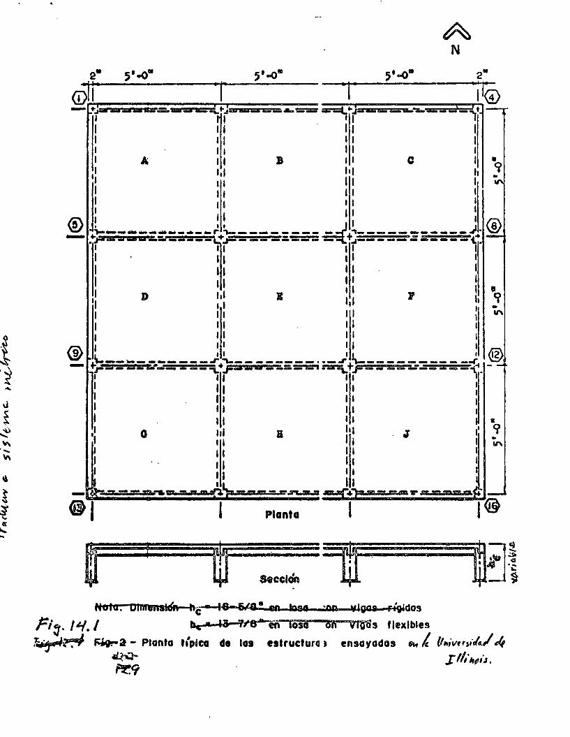
A N
2. 5'...0. 5'..0111 5'-o• 2.
@r ·r ·¡· ·¡ r@ - +-rw:a:awAiiif.:..wu m"'-+-¡'"'w-== .... ===- =-=l¡ .. '( ... mrm-a--.. -¡•
1 .~: . : l : 1 1 1 1 1 1 1 A 11 B 11 C 1 •
,1 '" hl h <j 1 1 1 1 1 ll 1 11 11 1 1 1 1 1 1 1 1 11 1
® .L ________ .. __ )l_ ________ _ _;+~-----------) ® - TUWUU&~=:a--~~----=---¡¡----~-----~¡-
,1 D lal B : 11 71 t ·~
1 1 1 1 -1 11 11 : "' 1 11 1 1 1 1 1 1 1 1 1 ® 1 11 11 1
9 J....._ __________ .)+!,_ ________ , __ )+~----------.{. ® - rr--------- =--""L .r=----=---·~ r-- --:.r--=--1}--: :: ;: ~1 1 1 1 1 1 1 1 1 1 1 1 1 1 11 1 1 •
,l G 111 B 1111 . J 1' '?
1 11 1 1 ~ 1 11 11 1 1 1 1 1 1 1 1 1 1 1 1 1
1 11 - --"~- - •• n - ~ :::~;.c:::::;.;:•:.;=::;;:=:::;=n:;=:;=~~,
1 -
Planta
Se celen
Hola. OlmeusiÓR h~-8 614-• en toso "N! vigas rt~dos
ri:¡. ¡¿.,¡./ be. ¡¡. 91'8---eñloso oi'í vrolis flexibles
~~ ~a - Planta t(plca de las estructura 1 ensayadas "" ¿ IJ,.ivtrsr·lc./ 4 ~ I 11,-~t,ú. Pr.9
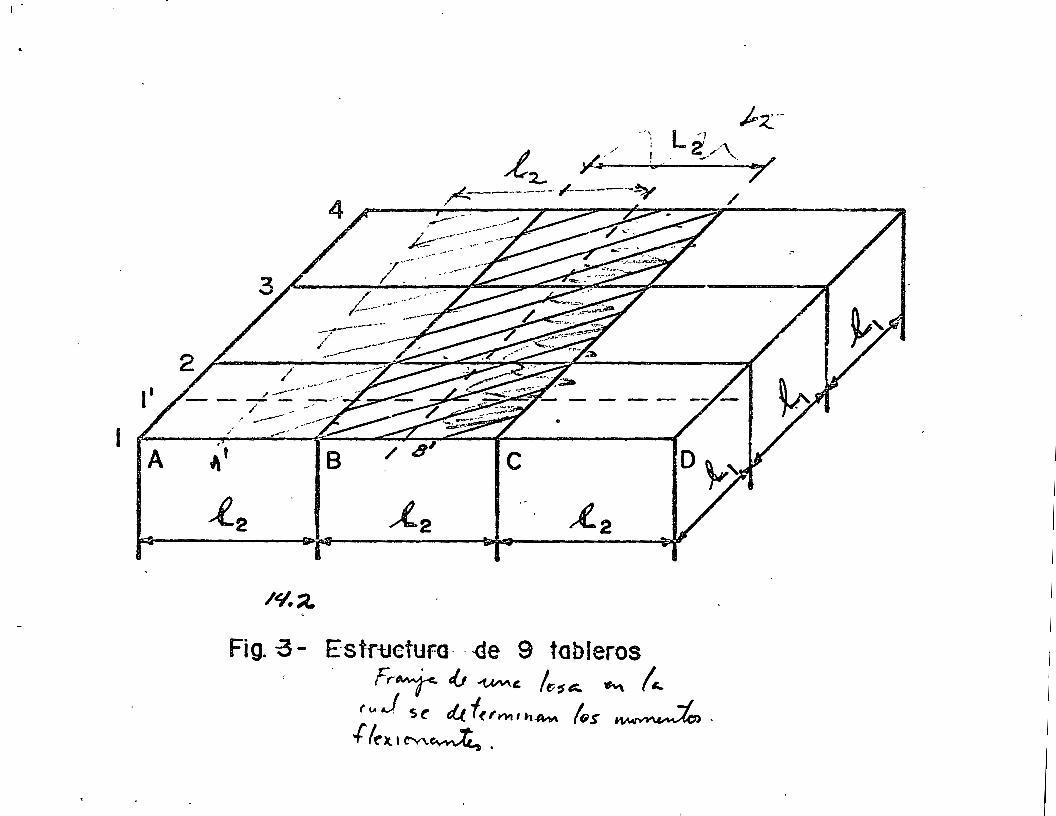
¡.
1
Fig. -a- Estr-uctura- --de 9 tobleros F,-~ I..J -'UN\' /t/1t::. ~ (.._
(uJ S( d.t.f(fwtlh~ /(;$ ~. + lt )t 1 t"'v\.~ •
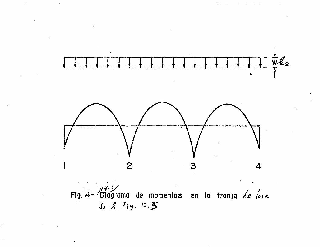
1 J. 1 1 1 1 1 1 1 1 1 1 J 1 1 1 ¡ 1> 1 = t.e 2
1 2 3 4
' """' ... -
Fig . .4:.. ~ama de moment~s en la franja Le lcs .,_ k fe_ ¡: 1 <] • I"J, 5
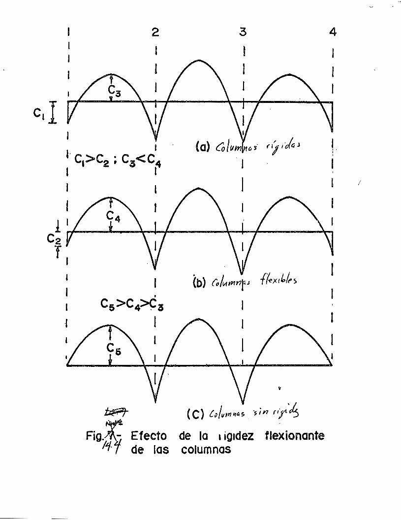
2 3
1 t l 1
c,I 1 1· 1
CI>C2 ; Ca<C4 '~'~J
1 l
!1 c2 T,
1
·1
l
t
(b) rolwmnrJ f(~x,lo/t,~
• Cs>C4~3 1
1
"
~ ( C) Cv/vrn~r~As _ ·sin ''r·~
Fig. r Efecto de la t ig1dez flexiononte í1~ de las columnas
4
1
1
1
L 1 '
1
1
1
1
1
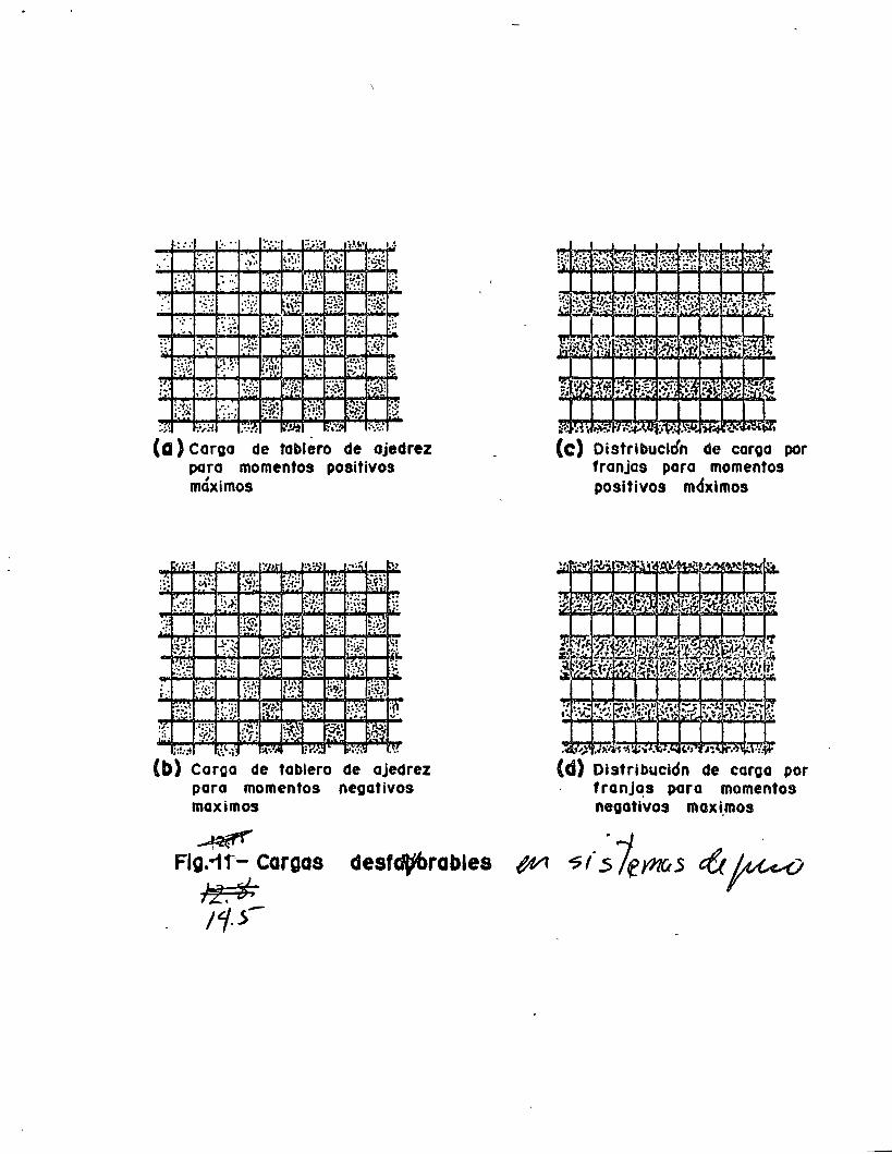
~=·· .~.:-~ ; .. ::-: ])! ~··'.:!' ;· .. ~ ...
(a) Carga de tablero de ajedrez para momentos positivos
... :;·
•" •.·.
•·
, . maxtmos
.•. ~: ;~.··.·
.:.:·< .. ~.
.:[!o .. ,, .. . •'
IT. O!' ·-:'·
j:!::' ~',\..; :I,•:IJI :r.1.: '••:\' 1.~~
(b) Carga de tablero de ajedrez poro momentos negativos maximos
~ Flg.1f- cargas
} 11:. if, 11·5-
desf.rables
o:·· a\ ~. r'~' ::.v.r~:·"~ ¡.\~ ;i:., ,_ ... , ....... ~,
(e) Distribución de caroa por franjas paro momentos positivos mdxlmos
Distribución de caroa por franjas paro momentos negativos maxi.mos
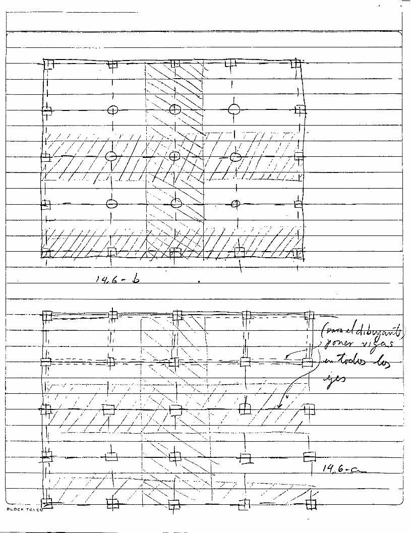
------,.-----.--,--..
( \ dl.
¡ ~\ -qp r,
\ '
' !
\, '•
~·. \
¡· 1
• ¡
\ •
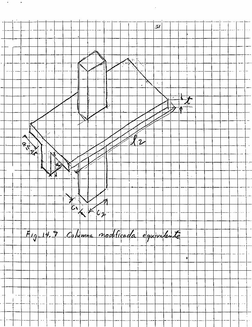
---- ---¡--- -+----1---+--1---+--1--4---- ---- -- __,_, _________ . __ : _____ ------4---j----f---¡---..L--+- --:--- --+--
____ ~------- ---- ---'--- -.~------~----- -- -----1---- ---f----Z- '---1 _j_ --~----- ----
J 1~ -/ \ " \ l -!--+--t--t----t--t--t---t--:.;J~I+---E--t--H'-t----t-l----t--t--1---J'!'or-f--:--H----!-..--l--l--l---1--1----l----\----v ¡ l>r:~--~~
- ~-- --- f-- -
-- -- -- --- --- --- ----- !'¿~K-~ c.-,.--- --~---- ---¡-- --- --- ---+-- _J __ I---+---1--- ---- --- - --- --
-r_,--~+-,_-r-+~~+-+-~-r-+~-~+-~-r-+~--~+-~-+~~~~4-~-~-
~~+f---t-f-----~~-:~c-L;: tJ:=J.,!V-... -.. :·+~--:I--_J..L--I~bLI-kl4f-1Mr.u'.q.ll~t:._:_r11~1nu.'.va~~f~~~ Pit;u~liut!l.t_ :t " "'l~-t-1 ~~,~,~~"ts-f---+¡-+--+-l--+--+----+---+---
-+--+-l-+--4--!--+--+--·t--J--t--J--+--t--~+--i--t--+---1f--+--t--+--+--+-l--+---l--l---- ---
___ ¡.-- --+----+---+--- ---1---- ---1-~---1---~-- ___ _l_~--1--- -- >--f-·--l---1f-+---+---~-l---+---+-- --- -
---~~-+_,--~+-~-r~~r-+-+-~~-+~~--~+-~-+-4~~+-4-~-+-4--~~-~ ·-t-t--t--+-+--t--+---+---+--1f--t---l--+--l---+---+-~~+--l---l---l--+--+-+-_j-
! 1 1 -~-r-+~,-+-+--r-+-4--~+-4-~-+-4--~+-4-~-+-4--~+-~~-+~--~+-~-
1
- -- -- -- ----- - --- --- -- -- ---- - -1--- ----- --- ---- --1-- --- ---- 1- --- --- --- --f----1- -- -- -- - - -- -
1 1 --~ -- ----:--- --- ---- 1 --1----- ---- -------------1-- ------1-------1---- -- J - --- -¡-
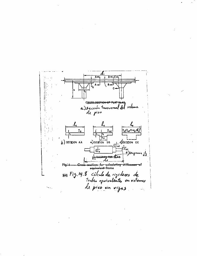
\''' ': '¡ '
i 11 !:: 1 ' 11 '
1 11' :¡ 1'
i¡' 1.,
' ol 1'
1 1
' ''
1 L
h
Cftft'!S SEC1'101G Of'=f!t;;m' SLAB:
b) SEC[.ION A A
1-
' !
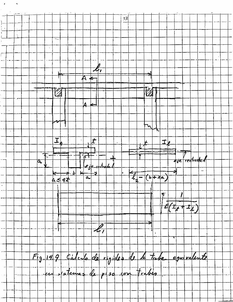
-f-----+--+--+--l--t--+--t--1·-r----l--1---1---+--t--~t-+--+-t--+--t---i----t------t------,__ --
------l---+--~-+---1--t-·--1r-+--'-'t--¡ ... ~~7i.a ~ "~ ,-J 'V~ ~> 4? ~-.:---~f-"'-----·------
-------------· -----t--1----iZ.W ~---f-----r---·r -·---------------· ·------
~-+-+~~~~~~~4-~~~~A~_¡~~~~~~~~~~~J~~~t~tJ¡--¡-r-r --+--+--+--f7'~r_J-~')_~I-vlf-f-'11-f-¡,'(J-1---4- vr---'~!j-f--f-~-f-~##f-1--1+'....:.... (/(/ ,,+l'_"'-t,j41-+IU--t~-J-t'"-' ~~J y-7'--j-.J-t-----f b'_"·~(OT:JTI-r-r---
--+--4--l-+-+---i-+-~"-+-t-+-+-t--t-+-+-t-t--t---t-r--r-t----t-t--rl-r--r-----r-----·-----·-t--+--+-t---t--1---t--·-tr··-+-_,-+--t--+-+--1,¡ .. !k.~-+--·-1----
-~ --¡------1--+-----·-
1 _u.. --f-----------r---r------+--+-·---;t----·-1--+--l ---------------.. ---------------------1--------
~~~-+-+-+-+~-4~--~~~+-+-+-~4-,_~~~~~-T-T---t-t~~-
f-++-+++-t--+~1/~--oft,o:...:J· ..,.91_: Cf~t )tt--=-f~#,.::t-J--1·--t--t--l=I=""'~-Jq-::·~~~b*>~· '¡-¡¡¡lll ··- 1 ~ " 1 v-. .,.. J'l q ··
lí 7t~f r"' e r:F'-1-+-+--i---l---f-+-1~-+---1--t--t--t-·¡--
----------+--1--l--·--· ----------------·-----------
--1----+-t-1---+--+---l--t--i-----+--l--'-1-----1r---t--t--r----1---+--t-----1---f--t---+--+--+--t-_,-·-
-_.!._-__ __¡__ ___ ~_ :__-~l_-___ -+~~-t-f-----1-_-_--+-+---~l----4+ -_-_ ++--_-~:_-1;_-_-+:~-~=~~=~==+-__ -_ -11-f-_-_-+_--~t~-_-_;r-__ -+-+ -__ -_ tr---t--J_ -_-___ i_-__ -_1-_1_ -__ -__ r __ -:-¡_
i t~
__ ¡___J _ _J__ _ _¡___¡_ _ __j___+-, --_-1----+-+--t--1---t-----:7--·-tt--t--+-, -+-i¡--L, ~-+-_ -+-. -1--t--!---·l---:: __ +-=::: __ -¡,----t-
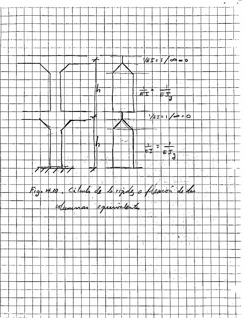
---~ i --- ~-· -~ --~ ----- ---¡-~ ~- ---r---~,_ -1--- __ __. __ t----;:-- ---~----~ --t---+--1--- --~---r -- -- ---,-- 1
-~-~~---r--~---~~-4--~--+--+--+--~-+--ll--~--4--+--~--+--+--+--l-~~~---
. - - --- - --- -- . --- --- --- - --- ---- --- -t----1-- -- --- -1---1-··-- ·-~~---- -~-· 1--·---~ ~- -~ -- ,. ___
..,~-
11 ' 1
V ,.
. ___.
~ - - !--, - ....... .--. -.::;;-. ~J --
i -1 ' ~---
¿' ' ' '
--t---1-------- ---- --~r----- ' ··\- - ' ' ' ' ,-·- ;,, ,• ·-~~--~..:.....·-+-f---t---1--'--
/~o 14~-lt) el¡ lcw.'•' t:"~- .L ,,..;,_~ r. z.:'¡,hl~~:,:.~ l,¿
/
.. .. :
--- 1---- ---- --- - -- --- - - --- --+---1---+--+---¡_...-~--t____:-1-..:- -- -----lf-----1-----!---·---t--+--~--1-
--- --1--- ---j----j- ----- ------1------ 1--- --1-----1--+--,;__ ---1-- __:.:..__ ~-- ----1---1----
-- l--!--·-1--- --- t-. - --- - -+----+---1----+-----l---1---1---1----+--~ --+-----+---1---4---+---+--+----1---t--+--!--
- -¡- --+--!----+--1 ____ ¡_ -¡
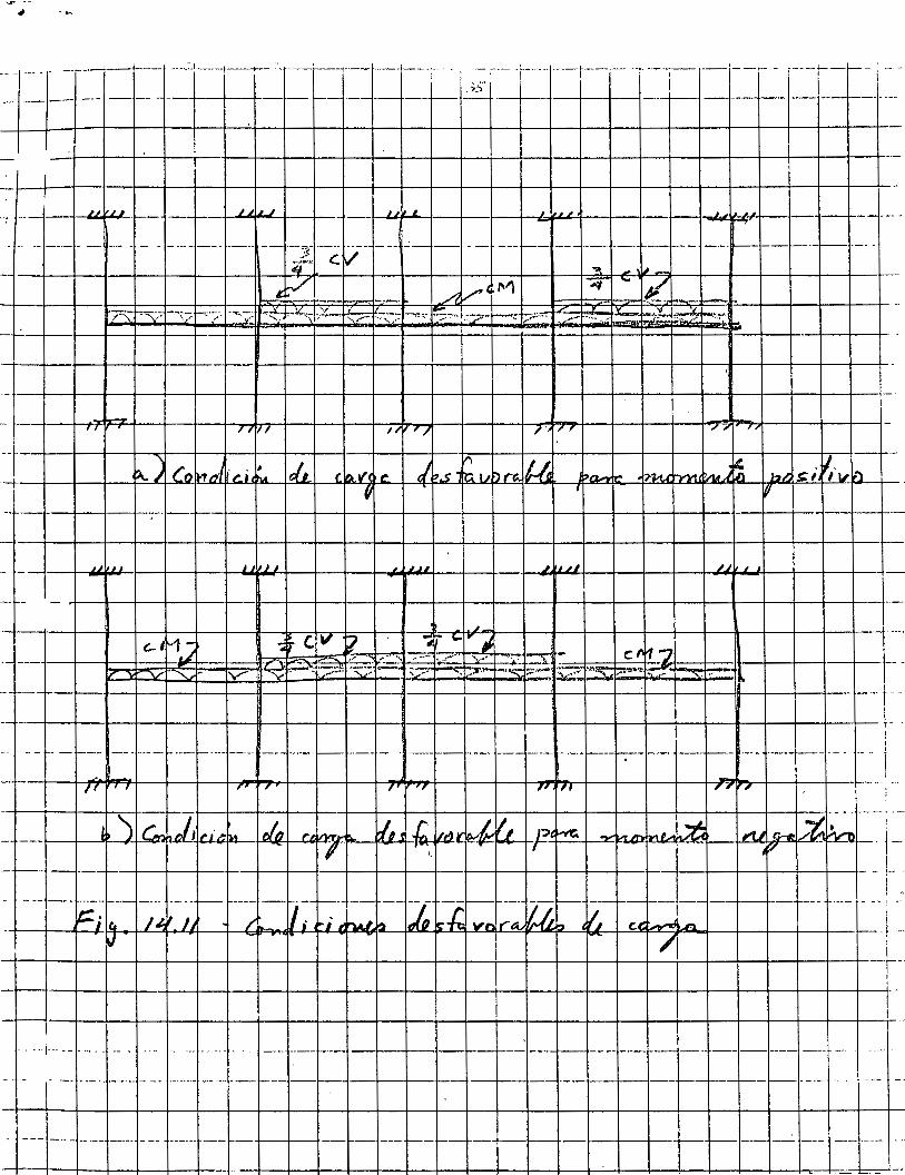
--- .... - -------1---- __ :.L.---t---r---:_---t----t------f---¡--·--' -:-- .:.. ... ----[---~------- ----, - --'----- -----¡--¡-- ¡ ---' 1 ~-;- ' 1
- -- --- -- - - 1-- ----1-- -- f---1_:_:_ - ----1--1- --!---- -- -- ---- ...
1 1
-.- -- ----t~Lw'-~0+-'L•--'~+--
TI 1 1 ., , , -.,. 1 , r
- ---+--+-4---f----l--+--+--+---+--+--+---t--+--f----l--~-+-+---t--+---lf----l--~-+--+--+---t---t-+
1 J 1 1 1 ~~
----1·--t--t~~~~~~M~~~~~~-::ivr~i-~-~~:f~=-'~-~-v~~~~.:?~~~-~*~§-~··p,§··~~-~~~~~~,~!.~-~ .. ~~~~-~~~~-~bs,~~~~~~~~~-~?~~~~l~r-i--i·--t-~~: -----r--r--r--r--+--+--+-~--+--+--+--+--~-+--~-+--+--+--+--+--+--+--+-~--+--+--+--r----r~-
1
------ -------- ··--1-------- --+--~---~--- -· ·- ----------- -1---+---1--·f---4-- --¡----------
- -1' , ,, , , ., 7' r1T ,, .,
1 ) [ Cn , j,t-lt"-I'··~+!M-+1-~( IJ-+--t---+---1-~-r 1-+ ~--+.C.I_-,.,, ... 1-l¿--t-~-+--J'?-+lk----11--......... +-L..--""+,..,-. "-+·---l ~-+-l"t-tJ+!J-«--+i/--[,·v-+';._'_ ~ f V
!
. !--! - r---r- ---+--t--t--t--t---+--+--t--t--l--4-+-t--+-+--+-+--4--l---l--+--+--+--l--+--l- - !- .. 1 ! 'J
- ------ --------- ---- ---- f-- ----- ·-1---- -- --¡--F --1--- --· í/-f--- -- ¡- ---+---+-- --- ---- -- i ·-·
+--f---{-~_..¡:iq'le.!J--J-...4/~' .:;+if...JJ.:Jlr J ___:_H/~~~(-/1-;· ~-¡f...J· ~¡..Mo"f#t...:~_4JZitMU!(g_.;i~CJ.· .h~v~f'l! r..t!·· ~411/4.~Ú.~b~•~~~~W..J:C.~t:~~~-..n.a--l---f---l---l--l---1-- .11 __
~ - 1 ~ -71 1
--r··
.... .-¡- ..... ·-···.-. -·-- -- ... -- .. ·---- -- ------- --1---1----1--~---1--1----1----------- -------·-- ---
¡· -- ..... -----¡---- ·------ -- --- . - t--- -r-· '--1-~---~--~ --1---f----+---i---~- -1---1---1---1--.- ·-
-·--·- ---- --+--+-~- -- --- ~- r-- - --- - --+--f----+----1--- --- - - ... - -- ·---
1 1
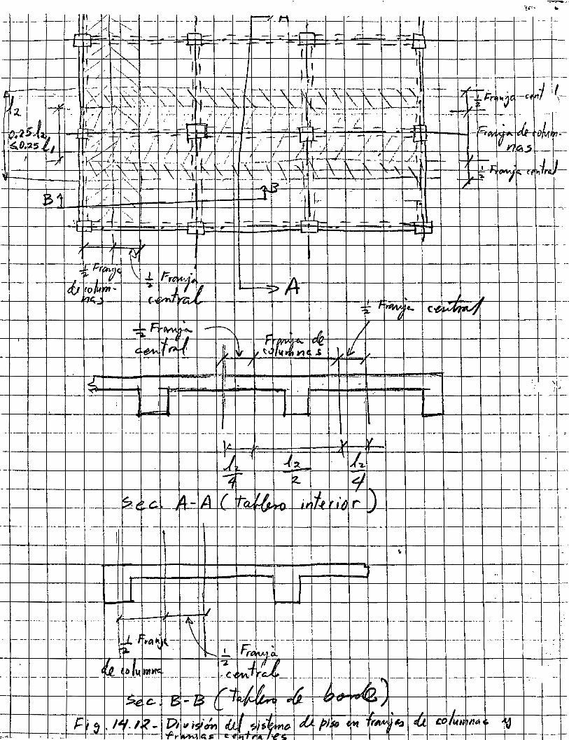
1,/ -< t'-, - ----- -- --- - --+-----1--j----------- -----J L /1( "-- -------------- ------- _t-- -~-b - ' , '- - -....:::' - -·-h- - -- 1 - - ¡-. -~
'
--¡---¡--¡-_ ---- ----~---__ ---r--- -~---------- --~-------- --~------ ___ -+--+---#·· ~· ~--L-1-L -_-r-· __ ---~----------- -- -------- ---+--+--~---- ---------- --- T \¡. ,.., lv
~=~=~=~=~=~~=~=~=~::::t::::t:J::·r:~:;~~=!..~:!~'\~~~~~::~::::~~~~=~=~=~1 =~=~-~---- -t---+---1----+--- +--+--+---l-+-+--+--+-3_r ~ 4 -- ----1--+--+--l
~ ~' e ~ -1 A (=-" 1tn1a...---t~-:-":-t L.W\-r-ú+~ f.--t-.,~-,~·~.·-r-.,..~)-+--+---+--+--+---l--+-- f--- -- - -
-- "'t--\vY¡<~ov-~~~--4''t...~_~lo"'td--i--+-+--f--~--1--l----l-- ---- -
-- f------- ------1-- - ----+--- f-.-- --r----t--+---t--+----+--+--!-~1-----1-- ---f- ---f-- --------- --
1 __ ,_¡-¡-~~~-r~~~~~-+~~~+-~~-+-+~~~+--L 1 ---
-~¡-¡-~~~-r~¡~+r~~~~~~~~~-+-+~~4-+-+-++-++H-HFRlF:F=+FF:::t=t:::W~+=t:=W-___J_U-j__j__j" _J~l- __ ~-r-¡--t-r-i-~~~-r~t-+-~,/-r-t-~-4--~~-+--~~-+--~~-+--~~~--~----_-- __ -_-_ ~~--~ -~~~ ~= ----- -~:~f: ~~· .)~ ! 't---.. ___ ---.- -~r-e fv.-··~~-~ j -·t-._:::------- ---- --- --- ---- ----- -- -¡--
··:: _, "" ' \ " rr. - ----¡ 1 ' . ---- ----j--1---- -- -- , - (i _o.. '
Related Documents