Edvantage Science AP ® CHEMISTRY 1 Big Idea 1 and 2 Order your own copy now Chapter 6 www.edvantagescience.com

Welcome message from author
This document is posted to help you gain knowledge. Please leave a comment to let me know what you think about it! Share it to your friends and learn new things together.
Transcript

Pantone 356
c = 95
m =
0y =
100k =
27
r = 0
g = 133
b = 63
Hex =
# 00553F
Pantone 662
c = 100
m =
71y =
0k =
18
r = 0
g = 75
b = 145
Hex =
# 004B91
Edvan
tage Scien
ce AP®C
HEM
ISTRY
1
H������������
����
�������������
����
��
�����������
�����
���������������
�����
���������������
�����
��������������
�����
����������
�����
�����
���������������
����
��
��������������
�����
��������������
�����
�����������
�����
�����
��������������
�����
��������������
�����
���������������
�����
�������������
�����
���������������
�����
����������������
�����
��
�������������
�����
Rf
������������������
����
��������������
�����
��
������������
�����
����������������
�����
Db
������������
����
�������
��������
�����
��
����������
�����
�����
���������������
�����
Sg
���������������
����
��
��������������
�����
Tc�����������������
�����
���������������
�����
Bh
������������
����
�����������
�����
�����������
������
�����
��
������
������
�����
Hs
������������
����
�������������
�����
���������������
�����
���������������
�����
Mt
���������������
����
��
�����������
�����
�����������������
�����
����������������
�����
Ds
������������
�����
����
�������������
�����
��������
������
�����
������
������
�����
Rg
����������������
����
�����������
�����
������
���������
�����
Hg
�������
������
�����
Cn
����������������
����
�����������
������
�����
��
�������������
�����
��������������
�����
���������������
�����
�����������
���������
�����
��������������
������
�����
��
���������
������
�����
��������������
�����
Pm����
�����������
�����
Np
���������������
�����
����������
������
�����
Pu���������
�����
�����
����������������
�����
Am
���������
�����
�����
��
����������������
�����
Cm������
�����
������
���������������
�����
Bk
��������������
������
��
����������������
�����
Cf
����������������
������
��
�������
������
�����
Es�����������
�����
������
��������������
�����
Fm�������
�����
�������
���������������
�����
Md
�����������
�����
�������
��
���������������
�����
No
�������������
�������
�����������
����
������������
����
N�������������
����
O�����������
����
F�������������
����
Ne����
�����
���
��
��������
�����
�����
���������
�����
�����
����������������
�����
�������������
�����
Cl
�������������
�����
Ar�����
�����
���
��
������������
�����
��
���������
�����
�����
��
������������
�����
����������
�����
�����
Br
�������
�����
�����
Kr
������������
������
��������������
�����
�����������
�����
�������
���������
�����
�����������������
�����
�������������
�����
Xe�����
������
������
����������������
�����
������������
�����
������
���������
�����
����������
�����
�����
��
�������������
�����
Rn�����
�����
�������
Uuq
����������������
����U
up�����������
�����
����U
uh����������
�����
����
Uus
����������������
����U
uo����������
�����
����
Uut
��������������
����
He������
����
��
������������
����������
����
�����������
����
��������
������
�
�����������������
������
����������
���
����������������
�����
Lr���
������������
����
H������������
����
1
2
34
56
78
910
11
12
13
14
15
16
17
18
1234567
67
Gro
up
Period
Transition Elements
�����Gas
LiquidSynthetic
Based on
carbon-12
Edvantage Science AP® CHEMISTRY 1Big Idea 1 and 2
Order your own copy now
Chapter
6www.edvantagescience.com

Pantone 356c = 95m = 0y = 100k = 27
r = 0g = 133b = 63Hex = # 00553F
Pantone 662c = 100m = 71y = 0k = 18
r = 0g = 75b = 145Hex = # 004B91
AP Chemistry 1Copyright © 2014, Edvantage Interactive
All rights reserved. No part of this publication may be reproduced or transmitted in any form or by any means, or stored in a database or retrieval system, without the prior written permission of Edvantage Interactive.
Please contact publisher for ISBN
Reprint Aug 2015
Care has been taken to trace ownership of copyright material contained in this text. The publishers will gladly accept any information that will enable them to rectify any reference or credit in subsequent printings.
Vice-President of Marketing: Don FranklinDirector of Publishing: Yvonne Van RuskenveldDesign and Production: Donna LindenbergProofreading: Eva van EmdenEditorial Assistance: Rhys SandnerIndex: Noeline BridgePhotos: p. 33, K. Jung; p. 34, Bureau international des poids et mesures (BIPM)
The AP Big Ideas at the beginning of each chapter are quoted from AP Chemistry: Course and Exam Description, revised edition, effective Fall 2013, published by the College Board, New York, NY. Advanced Placement, AP, and College Board are registered trademarks of the College Board.
QR Code — What Is This?The image to the right is called a QR code. It’s similar to bar codes on various products and contains information that can be useful to you. Each QR code in this book provides you with online support to help you learn the course material. For example, find a question with a QR code beside it. If you scan that code, you’ll see the answer to the question explained in a video created by an author of this book. You can scan a QR code using an Internet-enabled mobile device. The program to scan QR codes is free and available at your phone’s app store. Scanning the QR code above will give you a short overview of how to use the codes in the book to help you study. Note: We recommend that you scan QR codes only when your phone is connected to a WiFi network. Depending on your mobile data plan, charges may apply if you access the information over the cellular network. If you are not sure how to do this, please contact your phone provider or us at: [email protected]
COPIES OF THIS BOOK MAY BE OBTAINED BY CONTACTING:
Edvantage Interactive
E-MAIL:[email protected]
TOLL-FREE FAX:866.275.0564
TOLL-FREE CALL: 866.422.7310
Authors
Cheri SmithYale Secondary
School District 34 Abbotsford
Gary DavidsonSchool District 22 Vernon
Megan RyanWalnut Grove Secondary School District 35 Langley
Chris TothSt. Thomas More Collegiate
Burnaby
Program ConsultantLionel Sandner
Edvantage Interactive
© Edvantage Interactive 2014 Chapter 6 Patterns in Chemistry 305
6 Relationships and Patterns in Chemistry
By the end of this chapter, you should be able to do the following:
• Describe the development of the modern periodic table• Draw conclusions about the similarities and trends in the properties of elements, with reference to the periodic table• Justify chemical and physical properties in terms of electron population• Demonstrate knowledge of various types of chemical bonding• Apply understanding of bonding to create formulae and Lewis structures
By the end of this chapter you should know the meaning of the following key terms:
• alkali metals• alkaline earth metals• atomic radius• covalent bonding• electrical conductivity• electron dot diagram• halogens• ionic bonding• ionization energy• Lewis structure• melting point• metal• metalloid• mole• noble gases• non-metal• polarity• transition metals• valence electrons
This chapter focuses on the following AP Big Ideas from the College Board:
Big Idea 1: The chemical elements are fundamental building materials of matter, and all matter can be understood in terms of arrangements of atoms. These atoms retain their identify in chemical reactions.Big Idea 2: Chemical and physical properties of materials can be explained by the structure and the arrangement of atoms, ions, or molecules and the forces between them.
AP Chemistry students get better grades with Edvantage Science. Good luck with your course! www.edvantagescience.com
306 Chapter 6 Patterns in Chemistry © Edvantage Interactive 2014
6.1 The Development of the Periodic Table
Warm Up1. Can you suggest the meaning of the word “periodic” in the term “periodic table”?
2. On what basis are the elements arranged in the modern periodic table?
3. What is true about chemical elements that appear in the same vertical column in the table?
Discovering an Elemental Order
Science in general and chemistry in particular exist because our human species has always had an insatiable desire to make sense of the world around us. We have relentlessly sought to explain nature’s phenomena, to solve her mysteries, and to discover her order and logic by deciphering the events and objects we encounter.
One of the most important and successful examples of such efforts is the development of the periodic table of the elements. This single document is arguably more valuable to chemists, and perhaps even society itself, than any piece of equipment, wonder drug, or process ever invented.
The periodic table had its beginnings in the early part of the 1800s. By 1817, 52 elements had been discovered. Although some had been known since ancient times, many new elements were being discovered using the energy available from the electric battery invented by Volta in 1800. Researchers saw the need to organize those elements and the enormous amount of information gathered about them into some kind of meaningful form. German scientist Johann Dobereiner noticed similarities within several groups of three elements such as chlorine, bromine, and iodine, which he called “triads.” These similarities gave chemists some evidence that an organizational scheme was at least possible.
In 1857, English chemist William Odling proposed that the elements could be divided into groups based on their chemical and physical properties. Many of those groups actually resemble the vertical columns in the periodic table today.
In 1862, French geologist Alexandre-Emile de Chancourtois arranged the elements by increasing atomic mass. He noted that elements with similar properties seemed to occur at regular intervals. He devised a spiral graph with the elements arranged onto a cylinder such that similar elements lined up vertically. When his paper was published, however, it was largely ignored by chemists. Unfortunately, de Chancourtois had left out the graph, which made the paper hard to understand. As well, he had written the paper from a geologist’s rather than from a chemist’s perspective.
In 1864, English chemist John Newlands noticed that similar properties seemed to repeat every eighth element in much the same way that the notes of a musical scale repeat every eighth tone. Newlands called this the “law of octaves” and it resulted in several similar elements being grouped together, but with limited success.
The Periodic LawThe most successful organization of the elements was arrived at independently and almost at the same time by the German chemist Julius Lothar Meyer and the Russian chemist Dmitri Ivanovich Mendeleev. The chemical community, however, ultimately awarded Mendeleev the majority of the credit.
In a paper submitted to the Russian Chemical Society in March 1869, Mendeleev arranged the elements into a periodic table and proposed the periodic law, which can be stated as follows:
AP Chemistry students get better grades with Edvantage Science. Good luck with your course! www.edvantagescience.com
© Edvantage Interactive 2014 Chapter 6 Patterns in Chemistry 307
If elements are arranged in order of increasing atomic mass, a pattern can be seen in which similar properties recur on a regular or periodic basis.
Notice that this is called a “law” rather than a “theory.” Theories attempt to explain why relationships or phenomena exist, whereas laws simply identify that they exist. We will see if we can supply the “why” by the end of this section.
Dmitri Mendeleev received most of the credit for several reasons. First, Mendeleev’s work was published a year before Meyer’s. Second, Mendeleev chose to concentrate on the chemical properties of the elements, while Meyer focused mainly on physical properties. Third, and most importantly, Mendeleev chose to leave several blank spaces in his table where he predicted as-yet-undiscovered elements with specific properties would eventually be placed. Because he had arranged similar elements vertically in his table, the location of those blank spaces effectively identified the properties that those elements would have upon being discovered. When the elements were eventually discovered, the predictions turned out to be extremely accurate.
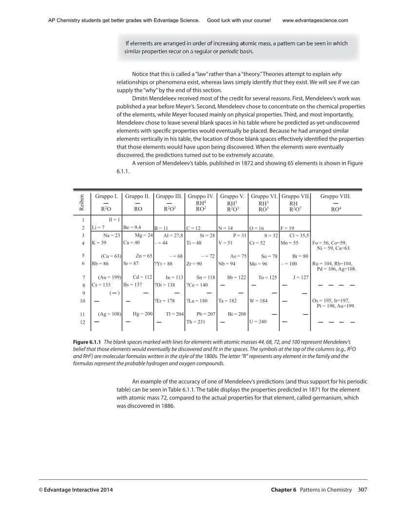
A version of Mendeleev’s table, published in 1872 and showing 65 elements is shown in Figure 6.1.1.
Gruppo I. Gruppo II. Gruppo III. Gruppo IV. Gruppo V. Gruppo VI. Gruppo VII. Gruppo VIII.nebieR R2O RO R2O3 RO2
RH4
R2O3RH3
RO3RH3
R2O7RH
RO4
Il = 1
Li = 7
K = 39
Rb = 86
Cs = 133
Na = 23
(Cu = 63)
(Ag = 108)
( )
(Au = 199)
1
2
3
4
5
6
7
8
9
10
11
12
Be = 9,4
Ca = 40
Sr = 87
Bs = 137
Mg = 24
Zn = 65
Hg = 200
Cd = 112
B = 11
– = 44
?Yt = 88
?Di = 138
Al = 27,8
– = 68
Tl = 204
In = 113
?Er = 178
C = 12
Ti = 48
Zr = 90
?Ce = 140
Si = 28
– = 72
Pb = 207
Sn = 118
?La = 180
Th = 231
N = 14
V = 51
Nb = 94
P = 31
As = 75
Bi = 208
Sb = 122
Ta = 182
O = 16
Cr = 52
Mo = 96
S = 32
So = 78
U = 240
To = 125
W = 184
F = 19
Mn = 55
– = 100
Cl = 35,5
Br = 80
J = 127
Fo = 56, Co=59,Ni = 59, Cu=63.
Ru = 104, Rh=104,Pd = 106, Ag=108.
Os = 195, Ir=197,Pt = 198, Au=199.
Figure 6.1.1 The blank spaces marked with lines for elements with atomic masses 44, 68, 72, and 100 represent Mendeleev’s belief that those elements would eventually be discovered and fit in the spaces. The symbols at the top of the columns (e.g., R2O and RH2) are molecular formulas written in the style of the 1800s. The letter “R” represents any element in the family and the formulas represent the probable hydrogen and oxygen compounds.
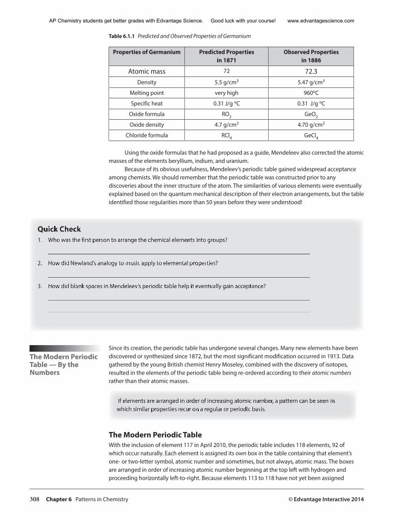
An example of the accuracy of one of Mendeleev’s predictions (and thus support for his periodic table) can be seen in Table 6.1.1. The table displays the properties predicted in 1871 for the element with atomic mass 72, compared to the actual properties for that element, called germanium, which was discovered in 1886.
AP Chemistry students get better grades with Edvantage Science. Good luck with your course! www.edvantagescience.com
308 Chapter 6 Patterns in Chemistry © Edvantage Interactive 2014
Table 6.1.1 Predicted and Observed Properties of Germanium
Properties of Germanium Predicted Properties in 1871
Observed Properties in 1886
Atomic mass 72 72.3Density 5.5 g/cm3 5.47 g/cm3
Melting point very high 960oC
Specific heat 0.31 J/g oC 0.31 J/g oC
Oxide formula RO2 GeO2
Oxide density 4.7 g/cm3 4.70 g/cm3
Chloride formula RCl4 GeCl4
Using the oxide formulas that he had proposed as a guide, Mendeleev also corrected the atomic masses of the elements beryllium, indium, and uranium.
Because of its obvious usefulness, Mendeleev’s periodic table gained widespread acceptance among chemists. We should remember that the periodic table was constructed prior to any discoveries about the inner structure of the atom. The similarities of various elements were eventually explained based on the quantum mechanical description of their electron arrangements, but the table identified those regularities more than 50 years before they were understood!
Quick Check1. Who was the first person to arrange the chemical elements into groups?
_______________________________________________________________________________________
2. How did Newland’s analogy to music apply to elemental properties?
_______________________________________________________________________________________
3. How did blank spaces in Mendeleev’s periodic table help it eventually gain acceptance?
_______________________________________________________________________________________
_______________________________________________________________________________________
The Modern Periodic Table — By the Numbers
Since its creation, the periodic table has undergone several changes. Many new elements have been discovered or synthesized since 1872, but the most significant modification occurred in 1913. Data gathered by the young British chemist Henry Moseley, combined with the discovery of isotopes, resulted in the elements of the periodic table being re-ordered according to their atomic numbers rather than their atomic masses.
If elements are arranged in order of increasing atomic number, a pattern can be seen in which similar properties recur on a regular or periodic basis.
The Modern Periodic TableWith the inclusion of element 117 in April 2010, the periodic table includes 118 elements, 92 of which occur naturally. Each element is assigned its own box in the table containing that element’s one- or two-letter symbol, atomic number and sometimes, but not always, atomic mass. The boxes are arranged in order of increasing atomic number beginning at the top left with hydrogen and proceeding horizontally left-to-right. Because elements 113 to 118 have not yet been assigned
AP Chemistry students get better grades with Edvantage Science. Good luck with your course! www.edvantagescience.com
© Edvantage Interactive 2014 Chapter 6 Patterns in Chemistry 309
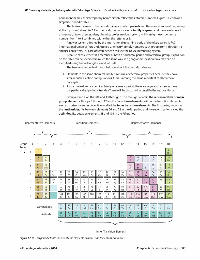
permanent names, their temporary names simply reflect their atomic numbers. Figure 6.1.2 shows a simplified periodic table.
The horizontal rows in the periodic table are called periods and these are numbered beginning at the top from 1 down to 7. Each vertical column is called a family or group and these are labeled using one of two schemes. Many chemists prefer an older system, which assigns each column a number from 1 to 8 combined with either the letter A or B.
A newer system adopted by the international governing body of chemistry called IUPAC (International Union of Pure and Applied Chemistry) simply numbers each group from 1 through 18 and uses no letters. For ease of reference, we will use the IUPAC numbering system.
Because each element is a member of both a horizontal period and a vertical group, its position on the table can be specified in much the same way as a geographic location on a map can be identified using lines of longitude and latitude.
The two most important things to know about the periodic table are:
1. Elements in the same chemical family have similar chemical properties because they have similar outer electron configurations. (This is among the most important of all chemical concepts.)
2. As we move down a chemical family or across a period, there are regular changes in these properties called periodic trends. (These will be discussed in detail in the next section.)
Groups 1 and 2 on the left, and 13 through 18 on the right contain the representative or main group elements. Groups 3 through 12 are the transition elements. Within the transition elements are two horizontal series collectively called the inner transition elements. The first series, known as the lanthanides, fits between elements 56 and 72 in the 6th period and the second series, called the actinides, fits between elements 88 and 104 in the 7th period.
��
���
����
���
����
����
����
���
����
����
����
����
����
����
���
����
����
����
�����
���
����
����
�����
����
����
���
�����
����
����
����
�����
����
����
����
�����
����
����
����
�����
����
����
����
�����
����
����
����
�����
����
����
����
�����
��
����
����
����
����
������
��
����
����
����
����
������
��
���
����
����
����
������
��
���
����
����
����
������
��
����
����
���
����
������
���
����
����
����
����
����
������
����
����
����
����
����
����
����
���
����
����
����
����
����
����
����
����
����
����
����
����
����
����
����
�����
����
�����
����
�����
����
�����
����������������������� ������������������� �����������������������
�������������������������
�����������
���������
� � � � � � � � � �� �� �� �� �� �� �� �� ��
�
�
�
�
�
�
�
�����������
Figure 6.1.2 This periodic table shows only the element’s symbols and their atomic numbers.
AP Chemistry students get better grades with Edvantage Science. Good luck with your course! www.edvantagescience.com
310 Chapter 6 Patterns in Chemistry © Edvantage Interactive 2014
Consider the periodic table in Figure 6.1.2. The first distinction among the elements relating to their properties that we will discuss is their classification as metals, non-metals, or metalloids. The “staircase” line descending from group 13 down to group 16 separates metals on the left side from non-metals on the right.
About three-quarters of the elements are metals, including some main group elements and all of the transition and inner transition elements. Properties of metals include:
• solids at room temperature, except for mercury, which is a liquid• generally shiny or lustrous when freshly cut or polished• good conductors of heat and electricity• generally malleable, which means they can be rolled or hammered into thin sheets• generally ductile, which means they can be rolled or stretched into wires • generally flexible as thin sheets or wires• during chemical changes, tending to give up electrons relatively easily to form cations
The non-metals are located in the upper right portion of the table. Properties of non-metals include:
• usually gases or brittle solids at room temperature, except for liquid bromine• solid non-metals ranging in appearance from dull or lustrous and translucent to opaque• poor conductors of heat and electricity• during chemical changes, tending to gain electrons from metals to form anions or share electrons
with other non-metals.
Along the staircase line are several metalloids (also called semi-metals), including the elements boron, silicon, germanium, arsenic, antimony, tellurium, and polonium. These solid elements are semiconductors, which mean they are poor electrical conductors at room temperature, but become better conductors at higher temperatures. This is opposite to how metal conductivity varies with temperature. Metals become less conductive as temperature increases.
As we move right-to-left across a period and down a chemical family, the elements become more metallic. These changes involve both physical and chemical properties, and those and other trends will be discussed in the next section.
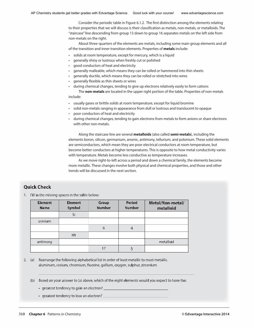
Quick Check1. Fill in the missing spaces in the table below:
Element Name
ElementSymbol
GroupNumber
PeriodNumber
Metal/Non-metal/metalloid
Si
osmium
6 4Mt
antimony metalloid
17 5
2. (a) Rearrange the following alphabetical list in order of least metallic to most metallic.aluminum, cesium, chromium, fluorine, gallium, oxygen, sulphur, zirconium
__________________________________________________________________________________
(b) Based on your answer to (a) above, which of the eight elements would you expect to have the:
• greatest tendency to gain an electron? __________________________________
• greatest tendency to lose an electron? __________________________________
AP Chemistry students get better grades with Edvantage Science. Good luck with your course! www.edvantagescience.com
© Edvantage Interactive 2014 Chapter 6 Patterns in Chemistry 311
A Closer Look at the Periodic Table
It is the number and type of outermost electrons that are primarily responsible for an atom’s chemistry. The members of a chemical family have similar numbers and types of outermost electrons. The outermost electrons that participate in chemical bonding are known as valence electrons. We will be discussing chemical bonding in more detail in a later section. For now, this section will introduce some families in the periodic table and the corresponding electron arrangements that will influence the bonding behaviour of their elements.
Group 1 — The Alkali Metals
Alkali metals are located on the far left side of the periodic table. This group includes lithium, sodium, potassium, rubidium, cesium, and the rare and radioactive francium. Alkali metals are all soft, silvery solids and the most reactive of all metals. The name of the group is based on the fact that the oxide compounds of the alkali metals dissolve in water to produce strongly basic solutions. They all corrode rapidly in air to a dull gray appearance, react vigorously with water to produce hydrogen gas, and readily form compounds with non-metals.
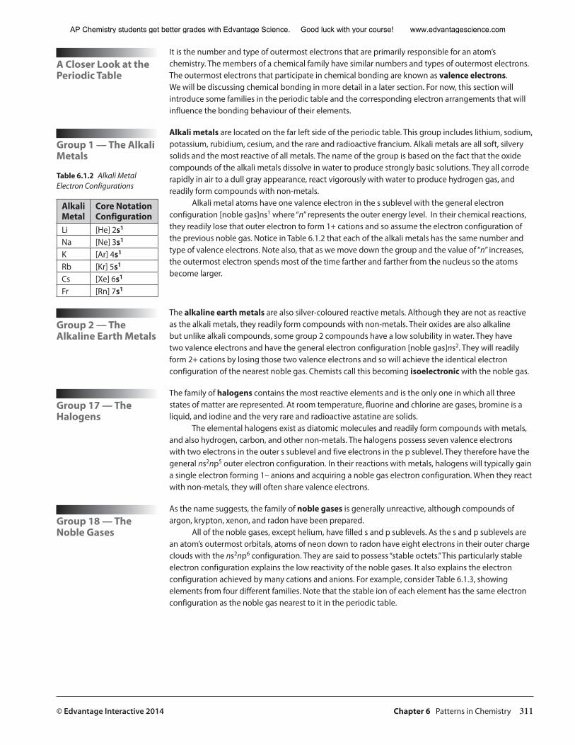
Alkali metal atoms have one valence electron in the s sublevel with the general electron configuration [noble gas]ns1 where “n” represents the outer energy level. In their chemical reactions, they readily lose that outer electron to form 1+ cations and so assume the electron configuration of the previous noble gas. Notice in Table 6.1.2 that each of the alkali metals has the same number and type of valence electrons. Note also, that as we move down the group and the value of “n” increases, the outermost electron spends most of the time farther and farther from the nucleus so the atoms become larger.
Group 2 — The Alkaline Earth Metals
The alkaline earth metals are also silver-coloured reactive metals. Although they are not as reactive as the alkali metals, they readily form compounds with non-metals. Their oxides are also alkaline but unlike alkali compounds, some group 2 compounds have a low solubility in water. They have two valence electrons and have the general electron configuration [noble gas]ns2. They will readily form 2+ cations by losing those two valence electrons and so will achieve the identical electron configuration of the nearest noble gas. Chemists call this becoming isoelectronic with the noble gas.
Group 17 — The Halogens
The family of halogens contains the most reactive elements and is the only one in which all three states of matter are represented. At room temperature, fluorine and chlorine are gases, bromine is a liquid, and iodine and the very rare and radioactive astatine are solids.
The elemental halogens exist as diatomic molecules and readily form compounds with metals, and also hydrogen, carbon, and other non-metals. The halogens possess seven valence electrons with two electrons in the outer s sublevel and five electrons in the p sublevel. They therefore have the general ns2np5 outer electron configuration. In their reactions with metals, halogens will typically gain a single electron forming 1– anions and acquiring a noble gas electron configuration. When they react with non-metals, they will often share valence electrons.
Group 18 — The Noble Gases
As the name suggests, the family of noble gases is generally unreactive, although compounds of argon, krypton, xenon, and radon have been prepared.
All of the noble gases, except helium, have filled s and p sublevels. As the s and p sublevels are an atom’s outermost orbitals, atoms of neon down to radon have eight electrons in their outer charge clouds with the ns2np6 configuration. They are said to possess “stable octets.” This particularly stable electron configuration explains the low reactivity of the noble gases. It also explains the electron configuration achieved by many cations and anions. For example, consider Table 6.1.3, showing elements from four different families. Note that the stable ion of each element has the same electron configuration as the noble gas nearest to it in the periodic table.
Table 6.1.2 Alkali Metal Electron Configurations
AlkaliMetal
Core NotationConfiguration
Li [He] 2s1
Na [Ne] 3s1
K [Ar] 4s1
Rb [Kr] 5s1
Cs [Xe] 6s1
Fr [Rn] 7s1
AP Chemistry students get better grades with Edvantage Science. Good luck with your course! www.edvantagescience.com
312 Chapter 6 Patterns in Chemistry © Edvantage Interactive 2014
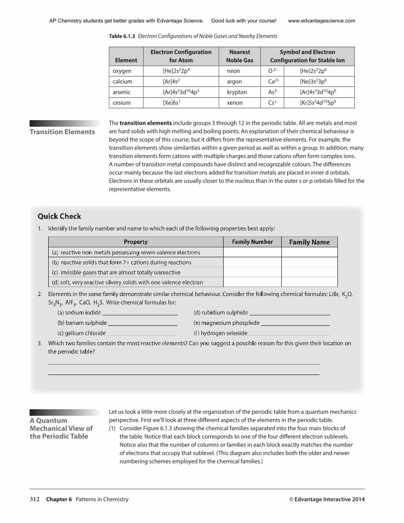
Table 6.1.3 Electron Configurations of Noble Gases and Nearby Elements
ElementElectron Configuration
for AtomNearest
Noble GasSymbol and Electron
Configuration for Stable Ion
oxygen [He]2s22p4 neon O 2– [He]2s22p6
calcium [Ar]4s2 argon Ca2+ [Ne]3s23p6
arsenic [Ar]4s23d104p3 krypton As3- [Ar]4s23d104p6
cesium [Xe]6s1 xenon Cs+ [Kr]5s24d105p6
Transition ElementsThe transition elements include groups 3 through 12 in the periodic table. All are metals and most are hard solids with high melting and boiling points. An explanation of their chemical behaviour is beyond the scope of this course, but it differs from the representative elements. For example, the transition elements show similarities within a given period as well as within a group. In addition, many transition elements form cations with multiple charges and those cations often form complex ions. A number of transition metal compounds have distinct and recognizable colours. The differences occur mainly because the last electrons added for transition metals are placed in inner d orbitals. Electrons in these orbitals are usually closer to the nucleus than in the outer s or p orbitals filled for the representative elements.
Quick Check1. Identify the family number and name to which each of the following properties best apply:
Property Family Number Family Name(a) reactive non-metals possessing seven valence electrons
(b) reactive solids that form 2+ cations during reactions
(c) invisible gases that are almost totally unreactive
(d) soft, very reactive silvery solids with one valence electron
2. Elements in the same family demonstrate similar chemical behaviour. Consider the following chemical formulas: LiBr, K2O,Sr3N2, AlF3, CaO, H2S. Write chemical formulas for:
(a) sodium iodide _________________________ (d) rubidium sulphide ___________________________
(b) barium sulphide _______________________ (e) magnesium phosphide _______________________
(c) gallium chloride _______________________ (f ) hydrogen selenide ___________________________
3. Which two families contain the most reactive elements? Can you suggest a possible reason for this given their location on the periodic table?
__________________________________________________________________________________________
__________________________________________________________________________________________
A Quantum Mechanical View of the Periodic Table
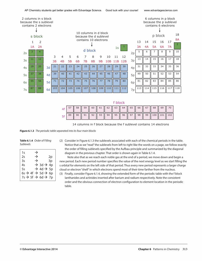
Let us look a little more closely at the organization of the periodic table from a quantum mechanics perspective. First we’ll look at three different aspects of the elements in the periodic table. (1) Consider Figure 6.1.3 showing the chemical families separated into the four main blocks of
the table. Notice that each block corresponds to one of the four different electron sublevels. Notice also that the number of columns or families in each block exactly matches the number of electrons that occupy that sublevel. (This diagram also includes both the older and newer numbering schemes employed for the chemical families.)
AP Chemistry students get better grades with Edvantage Science. Good luck with your course! www.edvantagescience.com
© Edvantage Interactive 2014 Chapter 6 Patterns in Chemistry 313
1
3
11
19
37
55
87
4
12
20
38
56
88
21
39
22
40
72
104
23
41
73
105
24
42
74
106
25
43
75
107
26
44
76
108
27
45
77
109
28
46
78
110
29
47
79
111
30
48
80
112
5
13
31
49
81
113
6
14
32
50
82
114
7
15
33
51
83
115
8
16
34
52
84
116
9
17
35
53
85
117
2
10
18
36
54
86
118
57
89
58
90
59
91
60
92
61
93
62
94
63
95
64
96
65
97
66
98
67
99
68
100
69
101
70
102
1 2
3 4 5 6 7 8 9 10 11 12
13 14 15 16 17
18
1s
2s
3s
4s
5s
6s
7s
71
103
4f
5f
3d
4d
5d
6d
2p
3p
4p
5p
6p
7p
1A 2A
3B 4B 5B 6B 7B 8B 9B 10B 11B 12B
3A 4A 5A 6A 7A
8A
f block
s block
d block
p block
14 columns in f block because the f sublevel contains 14 electrons
2 columns in s blockbecause the s sublevelcontains 2 electrons
10 columns in d blockbecause the d sublevelcontains 10 electrons
6 columns in p blockbecause the p sublevelcontains 6 electrons
Figure 6.1.3 The periodic table separated into its four main blocks
(2) Consider in Figure 6.1.3 the sublevels associated with each of the chemical periods in the table. Notice that as we “read” the sublevels from left to right like the words on a page, we follow exactly the order of filling sublevels specified by the Aufbau principle and summarized by the diagonal diagram in the previous chapter. That order is shown again in Table 6.1.4.
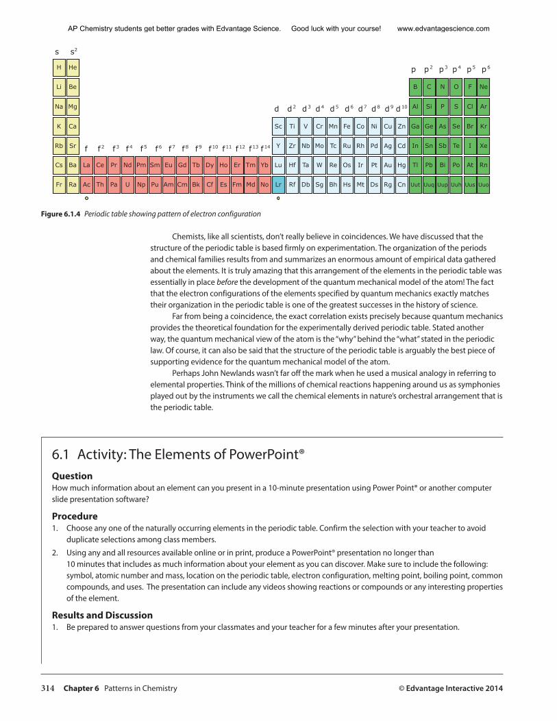
Note also that as we reach each noble gas at the end of a period, we move down and begin a new period. Each new period number specifies the value of the next energy level as we start filling the s orbital for elements on the left side of that period. Thus every new period represents a larger charge cloud or electron “shell” in which electrons spend most of their time farther from the nucleus.(3) Finally, consider Figure 6.1.4, showing the extended form of the periodic table with the f block
lanthanides and actinides inserted after barium and radium respectively. Note the consistent order and the obvious connection of electron configuration to element location in the periodic table.
1s ‡2s ‡ 2p3s ‡ 3p4s ‡ 3d ‡ 4p5s ‡ 4d ‡ 5p6s ‡ 4f ‡ 5d ‡ 6p7s ‡ 5f ‡ 6d ‡ 7p
Table 6.1.4 Order of Filling Sublevels
AP Chemistry students get better grades with Edvantage Science. Good luck with your course! www.edvantagescience.com
314 Chapter 6 Patterns in Chemistry © Edvantage Interactive 2014
H
Li
Na
K
Rb
Cs
Fr
Be
Mg
Ca
Sr
Ba
Ra
Sc
Y
Ti
Zr
Hf
Rf
V
Nb
Ta
Db
Cr
Mo
W
Sg
Mn
Tc
Re
Bh
Fe
Ru
Os
Hs
Co
Rh
Ir
Mt
Ni
Pd
Pt
Ds
Cu
Ag
Au
Rg
Zn
Cd
Hg
Cn
B
Al
Ga
In
Tl
Uut
C
Si
Ge
Sn
Pb
Uuq
N
P
As
Sb
Bi
Uup
O
S
Se
Te
Po
Uuh
F
Cl
Br
I
At
Uus
He
Ne
Ar
Kr
Xe
Rn
Uuo
La
Ac
Ce
Th
Pr
Pa
Nd
U
Pm
Np
Sm
Pu
Eu
Am
Gd
Cm
Tb
Bk
Dy
Cf
Ho
Es
Er
Fm
Tm
Md
Yb
No
Lu
Lr
s s2
f 2f f 3 f 4 f 5 f 6 f 7 f 8 f 9 f 10 f 11 f 12 f 13 f 14
d2d d3 d4 d5 d6 d7 d8 d9 d10
p2p p3 p4 p5 p6
Figure 6.1.4 Periodic table showing pattern of electron configuration
Chemists, like all scientists, don’t really believe in coincidences. We have discussed that the structure of the periodic table is based firmly on experimentation. The organization of the periods and chemical families results from and summarizes an enormous amount of empirical data gathered about the elements. It is truly amazing that this arrangement of the elements in the periodic table was essentially in place before the development of the quantum mechanical model of the atom! The fact that the electron configurations of the elements specified by quantum mechanics exactly matches their organization in the periodic table is one of the greatest successes in the history of science.
Far from being a coincidence, the exact correlation exists precisely because quantum mechanics provides the theoretical foundation for the experimentally derived periodic table. Stated another way, the quantum mechanical view of the atom is the “why” behind the “what” stated in the periodic law. Of course, it can also be said that the structure of the periodic table is arguably the best piece of supporting evidence for the quantum mechanical model of the atom.
Perhaps John Newlands wasn’t far off the mark when he used a musical analogy in referring to elemental properties. Think of the millions of chemical reactions happening around us as symphonies played out by the instruments we call the chemical elements in nature’s orchestral arrangement that is the periodic table.
6.1 Activity: The Elements of PowerPoint® QuestionHow much information about an element can you present in a 10-minute presentation using Power Point® or another computer slide presentation software?
Procedure1. Choose any one of the naturally occurring elements in the periodic table. Confirm the selection with your teacher to avoid
duplicate selections among class members.
2. Using any and all resources available online or in print, produce a PowerPoint® presentation no longer than 10 minutes that includes as much information about your element as you can discover. Make sure to include the following: symbol, atomic number and mass, location on the periodic table, electron configuration, melting point, boiling point, common compounds, and uses. The presentation can include any videos showing reactions or compounds or any interesting properties of the element.
Results and Discussion1. Be prepared to answer questions from your classmates and your teacher for a few minutes after your presentation.
AP Chemistry students get better grades with Edvantage Science. Good luck with your course! www.edvantagescience.com
© Edvantage Interactive 2014 Chapter 6 Patterns in Chemistry 315
6.1 Review Questions
1. What is the most important thing to know about the periodic table?
2. What significant modification to the periodic table occurred just before World War I?
3. Why do elements in the same chemical family have similar chemical properties?
4. (a) Where are the most metallic elements located on the periodic table?
(b) Where are the most non-metallic elements located on the periodic table?
5. Consider the properties listed for eight different elements. Match each element on the left to its property on the right by writing the element’s chemical symbol next to its property.
Element Properties Symbol
(a) chlorine found in carbohydrates and an elemental gas in 21% of the atmosphere
(b) silver soft conductor that reacts explosively with water producing H2 gas
(c) neon less than 30 g of this solid radioactive nonconductor exists on Earth
(d) cesium waxy yellow solid non-metal found in match heads, fertilizers, and detergents
(e) oxygen blue-gray metalloid used extensively in the computer industry
(f ) phosphorus very reactive green gas used in the trenches in World War I
(g) silicon shiny solid that is the best conductor of heat and electricity
(h) astatine invisible unreactive gas used in lasers and some electric street signs
6. Six different elemental properties are listed below corresponding to family numbers 1, 2, 6, 14, 17, and 18 in the periodic table. Write the appropriate family number next to each of the properties listed below. Each family number may be used only once.
Element Properties Family Number
unreactive gas used in electric street signs and comprising 0.93% of the atmosphere
shiny multivalent solid, good conductor, forms coloured compounds
soft silvery solid, good conductor, reacts vigorously with water
gray-white metalloid predicted by Mendeleev and discovered in 1886
reactive metal present in bones and teeth possessing two valence electrons
yellow-green gaseous non-metal and the most reactive of all the elements
AP Chemistry students get better grades with Edvantage Science. Good luck with your course! www.edvantagescience.com
316 Chapter 6 Patterns in Chemistry © Edvantage Interactive 2014
7. State four properties of elements classified as metals.
8. State four properties of elements classified as non-metals.
9. State a general rule for predicting the ion charges of many of the representative or main group elements.
10. Use your answer to question 8 above and write the formulas for the stable ions of the following:
(a) Be _______________________ (e) Ga ______________________
(b) Te _______________________ (f ) Se _______________________
(c) Cs _______________________ (g) In _______________________
(d) Ra ______________________
11. Identify three properties of the elements belonging to each of the following chemical families:(a) alkali metals
(b) alkaline earth metals
(c) halogens
(d) noble gases
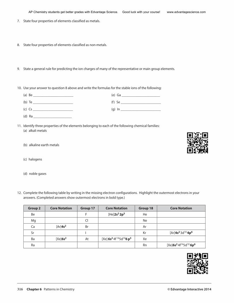
12. Complete the following table by writing in the missing electron configurations. Highlight the outermost electrons in your answers. (Completed answers show outermost electrons in bold type.)
Group 2 Core Notation Group 17 Core Notation Group 18 Core Notation
Be F [He]2s2 2p5 He
Mg Cl Ne
Ca [Ar]4s2 Br Ar
Sr I Kr [Ar]4s2 3d10 4p6
Ba [Xe]6s2 At [Xe] 6s2 4f 145d106 p5 Xe
Ra Rn [Xe]6s2 4f145d10 6p6
AP Chemistry students get better grades with Edvantage Science. Good luck with your course! www.edvantagescience.com
© Edvantage Interactive 2014 Chapter 6 Patterns in Chemistry 317
6.2 Periodic Trends — Regular Changes in Elemental Properties
Warm Up1. What attractive force is responsible for holding the cloud of electrons in place in atoms?
________________________________________________________________________________________
2. What effect would a strengthening of that force have on the sizes of atoms?
________________________________________________________________________________________
3. What might cause a strengthening of that force?
________________________________________________________________________________________
4. What might contribute to a weakening of that force?
________________________________________________________________________________________
Periodic TrendsAll of the chemical and physical behaviour of the elements is really a result of their electron configurations. In the last section, we discussed how similar outer-electron configurations explained the similar properties of elements within the chemical families of the periodic table. We will now concentrate on a second key concept associated with the organization of the elements in the table.
As we move across a period or down a chemical family, there are regular changes in elemental properties.
These consistent and predictable changes in elemental properties are known as periodic trends. Identifying and explaining them can be a great benefit when describing chemical interactions between atoms.
Periodic Trends in Atomic Size
In the quantum mechanical model, the outer boundaries of an atom depend on the size of a charge cloud in which electrons spend approximately 90% of their time. This means that the sizes of individual atoms cannot be determined in the same way as we might, for example, measure the size of objects such as marbles or grapefruits. In these cases, the object’s boundaries are hard and definite, unlike those of atoms.
However, we can estimate the sizes of atoms based on how close they get to one another when bonds form between them. This can be done by measuring the distance between the nuclei of identical adjacent atoms in an element sample and dividing that distance by two.
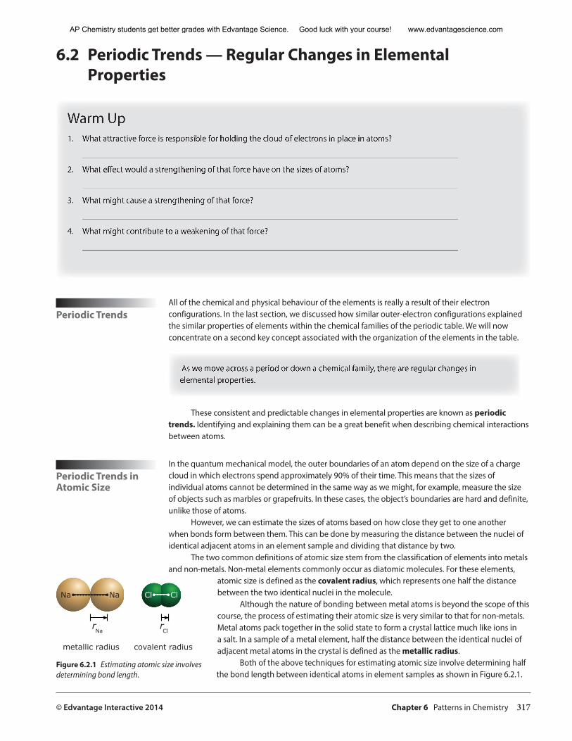
The two common definitions of atomic size stem from the classification of elements into metals and non-metals. Non-metal elements commonly occur as diatomic molecules. For these elements,
atomic size is defined as the covalent radius, which represents one half the distance between the two identical nuclei in the molecule.
Although the nature of bonding between metal atoms is beyond the scope of this course, the process of estimating their atomic size is very similar to that for non-metals. Metal atoms pack together in the solid state to form a crystal lattice much like ions in a salt. In a sample of a metal element, half the distance between the identical nuclei of adjacent metal atoms in the crystal is defined as the metallic radius.
Both of the above techniques for estimating atomic size involve determining half the bond length between identical atoms in element samples as shown in Figure 6.2.1.
NaNa Cl Cl
rNa
rCl
metallic radius covalent radius
Figure 6.2.1 Estimating atomic size involves determining bond length.
AP Chemistry students get better grades with Edvantage Science. Good luck with your course! www.edvantagescience.com
318 Chapter 6 Patterns in Chemistry © Edvantage Interactive 2014
Factors Influencing Atomic and Ionic Size
Let’s consider for a moment what might influence the size of an atom. Because an atom’s volume is really the result of a cloud of electrons, this question is really the same as asking: What affects the size of an atom’s electron cloud? Seen from that perspective, it makes sense that two opposing factors influence atomic size:
1. The number of energy levels present. As the number of energy levels (n) increases, the probability that outer electrons will spend more time further from the nucleus increases and so the atoms become larger.
2. The amount of nuclear charge “felt” or “seen” by the outer electrons. As this effective nuclear charge increases, the outer electron cloud is pulled closer to the nucleus and the atom becomes smaller. Chemists use the symbol “Zeff” to refer to the effective nuclear charge.
Of these two opposing factors, the one that predominates as we move across a period or down a chemical family will most influence how the sizes of those atoms change.
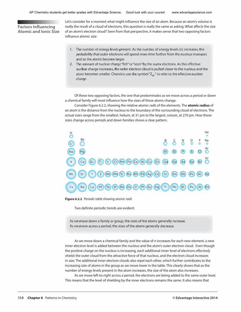
Consider Figure 6.2.2, showing the relative atomic radii of the elements. The atomic radius of an atom is the distance from the nucleus to the boundary of the surrounding cloud of electrons. The actual sizes range from the smallest, helium, at 31 pm to the largest, cesium, at 270 pm. How those sizes change across periods and down families shows a clear pattern.
Cs Ba La Hf Ta W Re Os Ir Pt Au Hg Tl Pb Bi Po At Rn
Rb Sr Y Z Nb Mo Tc Ru Rh Pd Ag Cd In Sn Sb Po At Xe
K Ca Sc Ti V Cr Mn Fe Co Ni Cu Zn Ga Ge As Se BrKr
Na Mg
Li
H
Be
Al Si P S ClAr
NeB C N O F
He
Figure 6.2.2 Periodic table showing atomic radii
Two definite periodic trends are evident:
As we move down a family or group, the sizes of the atoms generally increase.As we move across a period, the sizes of the atoms generally decrease.
As we move down a chemical family and the value of n increases for each new element, a new inner electron level is added between the nucleus and the atom’s outer electron cloud. Even though the positive charge on the nucleus is increasing, each additional inner level of electrons effectively shields the outer cloud from the attractive force of that nucleus, and the electron cloud increases in size. The additional inner electron clouds also repel each other, which further contributes to the increasing size of atoms in the group as we move lower in the table. This clearly shows that as the number of energy levels present in the atom increases, the size of the atom also increases.
As we move left-to-right across a period, the electrons are being added to the same outer level. This means that the level of shielding by the inner electrons remains the same. It also means that
AP Chemistry students get better grades with Edvantage Science. Good luck with your course! www.edvantagescience.com
© Edvantage Interactive 2014 Chapter 6 Patterns in Chemistry 319
the added electrons are ineffective at shielding each other from the increasing positive charge on the nucleus. The result is that Zeff on those outer electrons increases and the charge cloud is pulled closer and closer to the nucleus so the size of the atom decreases.
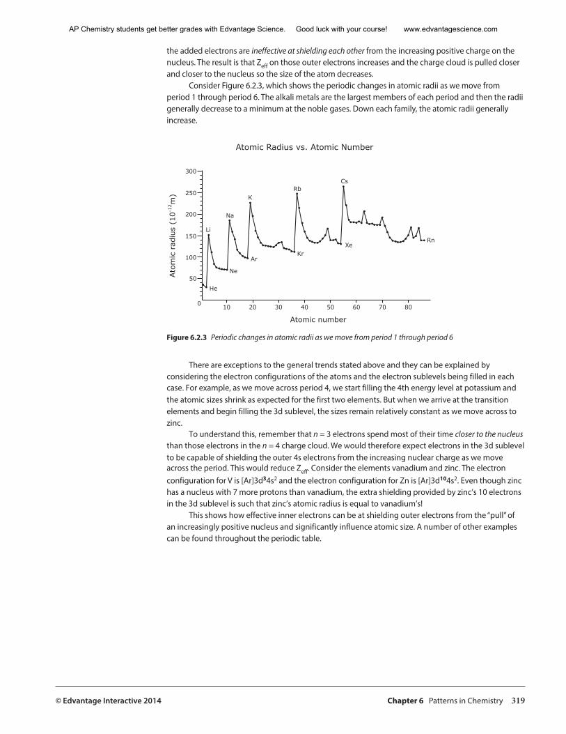
Consider Figure 6.2.3, which shows the periodic changes in atomic radii as we move from period 1 through period 6. The alkali metals are the largest members of each period and then the radii generally decrease to a minimum at the noble gases. Down each family, the atomic radii generally increase.
Ato
mic
rad
ius
(10-1
2 m)
0
50
100
150
200
250
300
Atomic number
10 20 30 40 50 60 70 80
Atomic Radius vs. Atomic Number
Rn
Cs
Xe
Rb
KrAr
Ne
He
Li
Na
K
Figure 6.2.3 Periodic changes in atomic radii as we move from period 1 through period 6
There are exceptions to the general trends stated above and they can be explained by considering the electron configurations of the atoms and the electron sublevels being filled in each case. For example, as we move across period 4, we start filling the 4th energy level at potassium and the atomic sizes shrink as expected for the first two elements. But when we arrive at the transition elements and begin filling the 3d sublevel, the sizes remain relatively constant as we move across to zinc.
To understand this, remember that n = 3 electrons spend most of their time closer to the nucleus than those electrons in the n = 4 charge cloud. We would therefore expect electrons in the 3d sublevel to be capable of shielding the outer 4s electrons from the increasing nuclear charge as we move across the period. This would reduce Zeff. Consider the elements vanadium and zinc. The electron configuration for V is [Ar]3d34s2 and the electron configuration for Zn is [Ar]3d104s2. Even though zinc has a nucleus with 7 more protons than vanadium, the extra shielding provided by zinc’s 10 electrons in the 3d sublevel is such that zinc’s atomic radius is equal to vanadium’s!
This shows how effective inner electrons can be at shielding outer electrons from the “pull” of an increasingly positive nucleus and significantly influence atomic size. A number of other examples can be found throughout the periodic table.
AP Chemistry students get better grades with Edvantage Science. Good luck with your course! www.edvantagescience.com

320 Chapter 6 Patterns in Chemistry © Edvantage Interactive 2014
Quick Check1. Which of the two opposing factors that influence atomic size predominates as we move across a chemical period? What is
the general result?
________________________________________________________________________________________
2. Which of the two opposing factors that influence atomic size predominates as we move down a chemical family? What is the general result?
________________________________________________________________________________________
3. In general, is “effective shielding” most evident going across a period or down a family? How can you tell?
________________________________________________________________________________________
Forces Affecting Ion Size
The same forces that influence the sizes of atoms also influence the sizes of ions and in the same way. Let’s consider these forces and rank the following species in order of size from largest to smallest: Al3+
, F−, Mg2+, N3-, Na+, Ne, O2–. Note that all of the ions have 10 electrons and are therefore isoelectronic with neon. Since each
species has the same number of electrons, we can assume that the amount of shielding is also the same for each. This means that the attractive force from each nucleus is the only factor influencing the size of each species. The greater the number of protons present, the stronger the attractive force on the electron cloud and therefore the smaller the atom or ion. This tells us that ranking the species in order of atomic number (positive charge on the nucleus) will also represent the order of decreasing size. Therefore, the answer is:
N3– > O2– > F− > Ne > Na+ > Mg2+ > Al3+
Periodic Trends in Ionization Energy
Ionization energy (IE) is defined as the minimum energy required to remove an electron from a gaseous atom or ion. The term is often used to mean the “first” ionization energy (IE1) whereby a neutral atom becomes a 1+ cation according to the following equation:
atom (g) + IE1 ➝ ion + (g) + e–
Ionization energy tells us how strongly an atom holds onto its outermost electrons. This is an important property because an element with a low IE1 will be more likely to lose electrons and form cations during chemical changes. A high IE1 might signal an element’s tendency to gain electrons and form anions or perhaps not forms ions at all.
We might expect that a large atom, whose outer electrons are held less tightly, would have a lower IE1 than a smaller atom whose outer electrons are held much more strongly. Said another way, as atomic size decreases, ionization energy should increase. This is, in fact, the general trend, as shown in Figure 6.2.4.
AP Chemistry students get better grades with Edvantage Science. Good luck with your course! www.edvantagescience.com
© Edvantage Interactive 2014 Chapter 6 Patterns in Chemistry 321
)lo
m/Jk( ygre
nE
noitazi
noI
Atomic number10 18 36 54 86
0
500
1000
1500
2000
2500
Period2
Period3
Period4
Period5
Period6
Rn
Tl
Xe
Cs
Cd
Kr
Rb
ZnAsBr
Ar
Cl
PS
Si
AlNa
K
OC
MgB
Li
H
He
Ne
F
N
Be
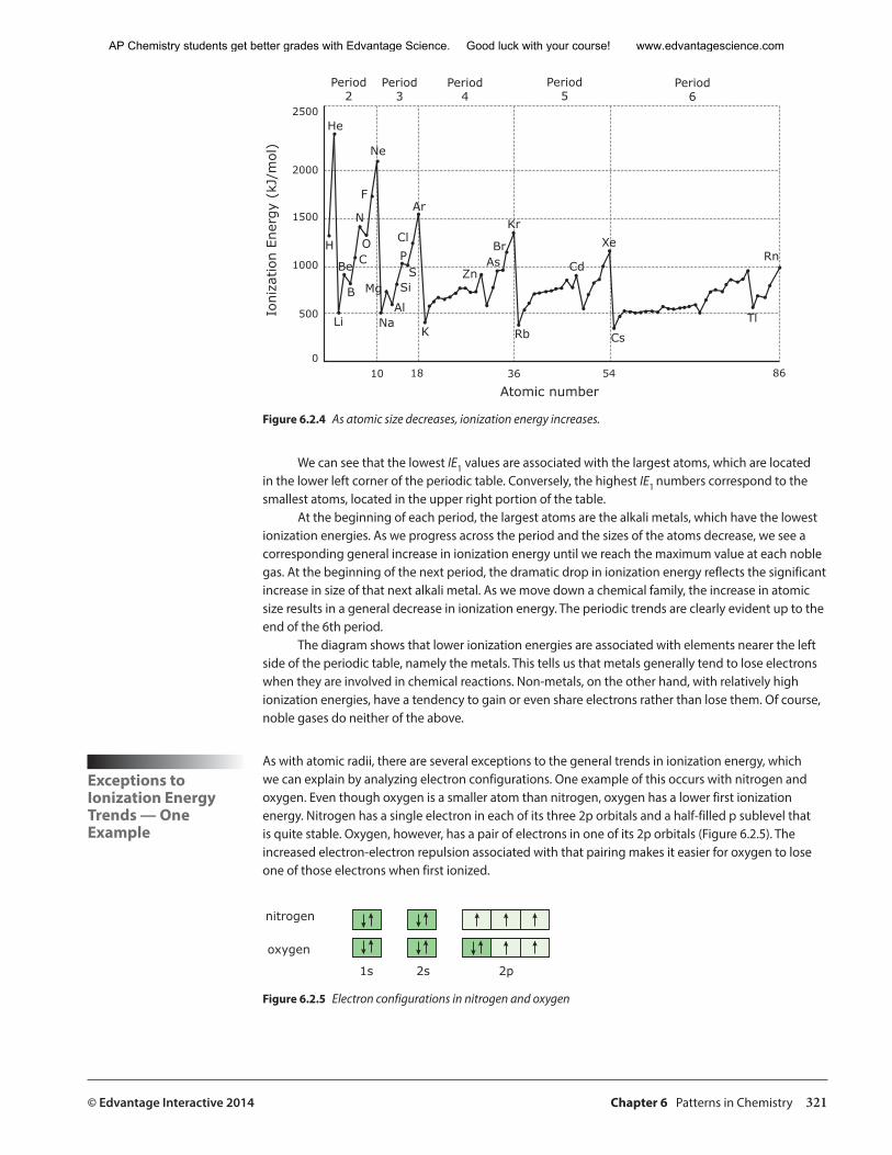
Figure 6.2.4 As atomic size decreases, ionization energy increases.
We can see that the lowest IE1 values are associated with the largest atoms, which are located in the lower left corner of the periodic table. Conversely, the highest IE1 numbers correspond to the smallest atoms, located in the upper right portion of the table.
At the beginning of each period, the largest atoms are the alkali metals, which have the lowest ionization energies. As we progress across the period and the sizes of the atoms decrease, we see a corresponding general increase in ionization energy until we reach the maximum value at each noble gas. At the beginning of the next period, the dramatic drop in ionization energy reflects the significant increase in size of that next alkali metal. As we move down a chemical family, the increase in atomic size results in a general decrease in ionization energy. The periodic trends are clearly evident up to the end of the 6th period.
The diagram shows that lower ionization energies are associated with elements nearer the left side of the periodic table, namely the metals. This tells us that metals generally tend to lose electrons when they are involved in chemical reactions. Non-metals, on the other hand, with relatively high ionization energies, have a tendency to gain or even share electrons rather than lose them. Of course, noble gases do neither of the above.
Exceptions to Ionization Energy Trends — One Example
As with atomic radii, there are several exceptions to the general trends in ionization energy, which we can explain by analyzing electron configurations. One example of this occurs with nitrogen and oxygen. Even though oxygen is a smaller atom than nitrogen, oxygen has a lower first ionization energy. Nitrogen has a single electron in each of its three 2p orbitals and a half-filled p sublevel that is quite stable. Oxygen, however, has a pair of electrons in one of its 2p orbitals (Figure 6.2.5). The increased electron-electron repulsion associated with that pairing makes it easier for oxygen to lose one of those electrons when first ionized.
nitrogen
oxygen
1s 2s 2p
Figure 6.2.5 Electron configurations in nitrogen and oxygen
AP Chemistry students get better grades with Edvantage Science. Good luck with your course! www.edvantagescience.com
322 Chapter 6 Patterns in Chemistry © Edvantage Interactive 2014
This reminds us that the repulsive forces between electrons, as well as the attractive forces affecting them from the nucleus, have a role to play in determining properties such as size and ionization energy.
Studying ionization energies allows us to do more than predict which elements might tend to lose or gain electrons during chemical changes. Investigating ionization energies also helps us identify which electrons are likely to be associated with those changes.
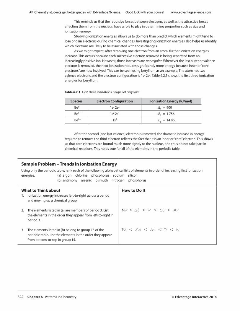
As we might expect, after removing one electron from an atom, further ionization energies increase. This occurs because each successive electron removed is being separated from an increasingly positive ion. However, those increases are not regular. Whenever the last outer or valence electron is removed, the next ionization requires significantly more energy because inner or “core electrons” are now involved. This can be seen using beryllium as an example. The atom has two valence electrons and the electron configuration is 1s2 2s2. Table 6.2.1 shows the first three ionization energies for beryllium.
Table 6.2.1 First Three Ionization Energies of Beryllium
Species Electron Configuration Ionization Energy (kJ/mol)
Beo 1s2 2s2 IE1 = 900
Be1+ 1s2 2s1 IE2 = 1 756
Be2+ 1s2 IE3 = 14 860
After the second (and last valence) electron is removed, the dramatic increase in energy required to remove the third electron reflects the fact that it is an inner or “core” electron. This shows us that core electrons are bound much more tightly to the nucleus, and thus do not take part in chemical reactions. This holds true for all of the elements in the periodic table.
Sample Problem – Trends in Ionization Energy Using only the periodic table, rank each of the following alphabetical lists of elements in order of increasing first ionization energies. (a) argon chlorine phosphorus sodium silicon
(b) antimony arsenic bismuth nitrogen phosphorus
What to Think about1. Ionization energy increases left-to-right across a period
and moving up a chemical group.
2. The elements listed in (a) are members of period 3. List the elements in the order they appear from left-to-right in period 3.
3. The elements listed in (b) belong to group 15 of the periodic table. List the elements in the order they appear from bottom-to-top in group 15.
How to Do It
Na < Si < P < Cl < Ar
Bi < Sb < As < P < N
AP Chemistry students get better grades with Edvantage Science. Good luck with your course! www.edvantagescience.com
© Edvantage Interactive 2014 Chapter 6 Patterns in Chemistry 323
Practice Problems — Trends in Ionization Energy1. Using only the periodic table, rank the following alphabetical list of elements in order of decreasing first ionization energy.
aluminum argon cesium magnesium rubidium silicon sodium sulphur
2. Using the periodic table, write the correct number in the space after each statement below:
Members of this chemical family have the highest IE1 in their period. ________
Members of this chemical family have the lowest IE1 in their period. ________
Members of this chemical period have the highest IE1 in their family. ________
Members of this chemical period have the lowest IE1 in their family. ________
3. The nature of the 2s sublevel is such that 2s electrons have a higher probability of being found closer to the nucleus than electrons in the 2p sublevel. Consider this and the following electron configurations:
beryllium: 1s2 2s2 boron: 1s2 2s2 2p1
Suggest a reason why boron’s first ionization energy is less than beryllium’s, even though boron is a smaller atom.
___________________________________________________________________________________________
An Introduction to Electronegativity
Our discussions so far have focused on the electron configurations, properties, and periodic trends associated with individual atoms of the elements. This has been directed towards an eventual understanding of how these atoms behave when they form chemical bonds.
Chemical bonding begins when the valence electrons in a region of space between two atoms are attracted by or “shared” between the adjacent nuclei. Each nucleus exerts an influence on those electrons, which ultimately determine the nature of the resulting bond.
To begin to describe this effect and the nature of the resulting bonds, let’s look at an elemental property associated with bonded atoms. It is one of the most important properties in chemical bonding.
Electronegativity is defined as the relative ability of a bonded atom to attract shared electrons to itself. Atoms with relatively high electronegativities (EN) tend to pull bonded electrons closer to their nuclei. Atoms with lower EN values have their bonded electrons pulled further away. As we’ll see in section 6.3, this will dictate not only the nature of the chemical bonds that form, but also the properties of the compounds containing those bonds.
We might expect that smaller atoms would have higher EN values since their nuclei would be closer to bonded electrons than the nuclei of larger atoms. We might also expect that larger atoms would therefore tend to have lower EN values. This is indeed the case, and because atomic size shows periodic trends, we shouldn’t be surprised that electronegativity does as well. In fact, the general trends in electronegativity are similar to those seen in ionization energy.
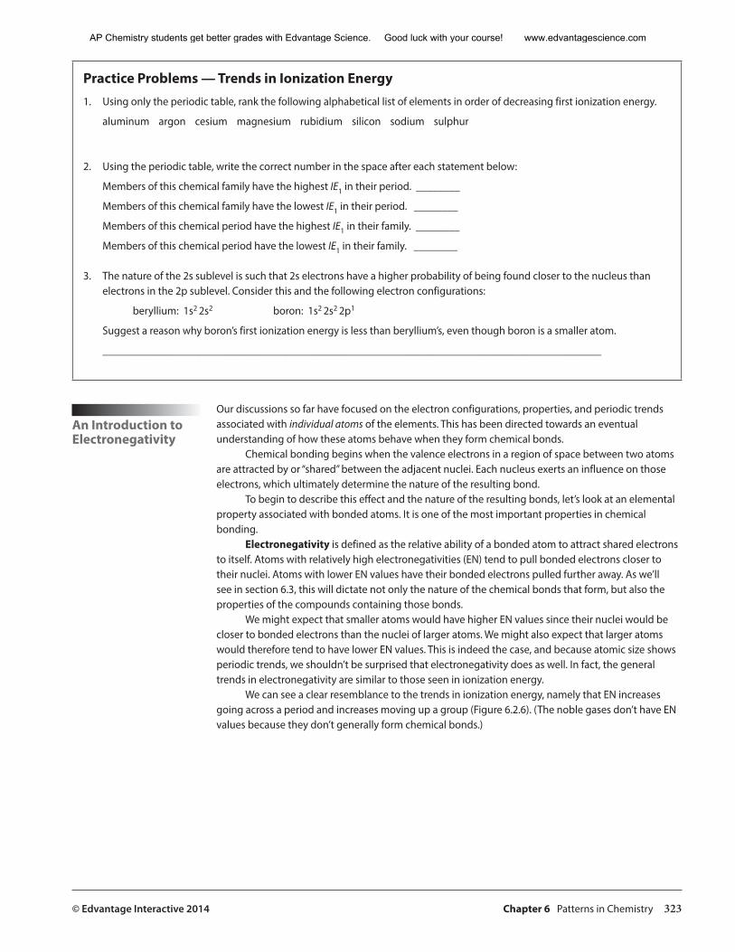
We can see a clear resemblance to the trends in ionization energy, namely that EN increases going across a period and increases moving up a group (Figure 6.2.6). (The noble gases don’t have EN values because they don’t generally form chemical bonds.)
AP Chemistry students get better grades with Edvantage Science. Good luck with your course! www.edvantagescience.com
324 Chapter 6 Patterns in Chemistry © Edvantage Interactive 2014
����
�����
�����
����
�����
�����
�����
�����
�����
�����
�����
�����
�����
�����
����
�����
�����
�����
����
�����
�����
�����
�����
����
�����
��
�����
�����
�����
�����
�����
�����
�����
�����
�����
�����
�����
�����
�����
�����
�����
�����
�����
�����
�����
�����
�����
�����
�����
�����
����
�� �����
�����
�����
�����
�����
�����
�����
�����
�����
����
����
����
����
����
��
�����
�����
����
����
�����
��
�����
�����
�����
�����
�����
��
�����
�����
�����
�����
����
��
�����
�����
�����
�����
�����
��
��
Increasing EN
Increasing EN
Figure 6.2.6 Periodic table showing trends in electronegativity
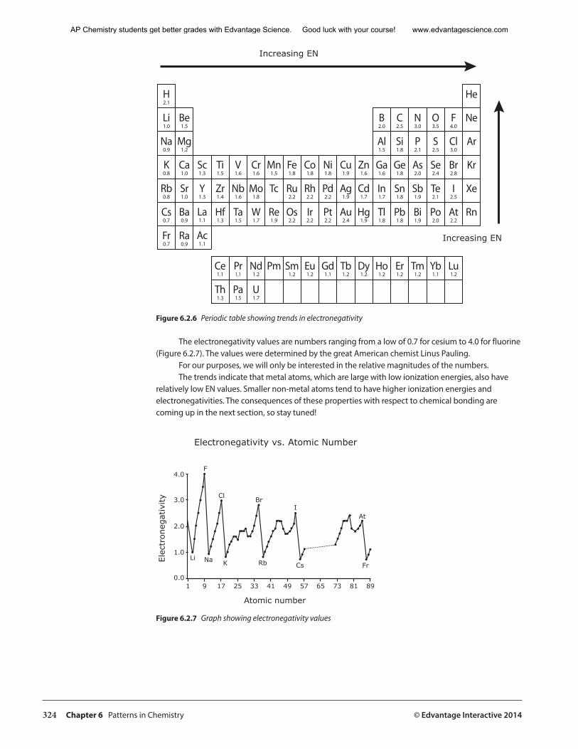
The electronegativity values are numbers ranging from a low of 0.7 for cesium to 4.0 for fluorine (Figure 6.2.7). The values were determined by the great American chemist Linus Pauling.
For our purposes, we will only be interested in the relative magnitudes of the numbers. The trends indicate that metal atoms, which are large with low ionization energies, also have
relatively low EN values. Smaller non-metal atoms tend to have higher ionization energies and electronegativities. The consequences of these properties with respect to chemical bonding are coming up in the next section, so stay tuned!
Elec
tron
egat
ivity
Atomic number
1 9 17 25 33 41 49 57
Electronegativity vs. Atomic Number
65 73 81 890.0
1.0
2.0
3.0
4.0
Li
F
Cl
Na K
Br
Rb
I
Cs
At
Fr
Figure 6.2.7 Graph showing electronegativity values
AP Chemistry students get better grades with Edvantage Science. Good luck with your course! www.edvantagescience.com
© Edvantage Interactive 2014 Chapter 6 Patterns in Chemistry 325
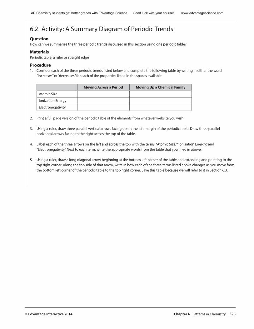
6.2 Activity: A Summary Diagram of Periodic TrendsQuestion How can we summarize the three periodic trends discussed in this section using one periodic table?
Materials Periodic table, a ruler or straight edge
Procedure1. Consider each of the three periodic trends listed below and complete the following table by writing in either the word
“increases” or “decreases” for each of the properties listed in the spaces available.
Moving Across a Period Moving Up a Chemical Family
Atomic Size
Ionization Energy
Electronegativity
2. Print a full page version of the periodic table of the elements from whatever website you wish.
3. Using a ruler, draw three parallel vertical arrows facing up on the left margin of the periodic table. Draw three parallel horizontal arrows facing to the right across the top of the table.
4. Label each of the three arrows on the left and across the top with the terms: “Atomic Size,” “Ionization Energy,” and “Electronegativity.” Next to each term, write the appropriate words from the table that you filled in above.
5. Using a ruler, draw a long diagonal arrow beginning at the bottom left corner of the table and extending and pointing to the top right corner. Along the top side of that arrow, write in how each of the three terms listed above changes as you move from the bottom left corner of the periodic table to the top right corner. Save this table because we will refer to it in Section 6.3.
AP Chemistry students get better grades with Edvantage Science. Good luck with your course! www.edvantagescience.com
326 Chapter 6 Patterns in Chemistry © Edvantage Interactive 2014
6.2 Review Questions
1. What is meant by the term “periodic trends”?
2. Why is it difficult to measure the sizes of individual atoms?
3. Two of the elemental properties discussed in this section show similar trends when moving across a period and up a chemical family. Identify these and the trend observed.
4. One of the three properties discussed shows periodic trends when moving across a period or up a family opposite to the other two properties. Identify this property and the trend observed.
5. Briefly explain why fluorine is a smaller atom than lithium. Consider which factor is predominating across a period.
6. Where are the largest atoms located on the periodic table?Where are the smallest atoms located on the periodic table?
7. The attraction of electrons to the nucleus and repulsion of the electrons between each other both influence the size of an atom or ion. Use this to complete the following statements. (a) A cation will always be ________________ (smaller or
larger) than its parent neutral atom because of _________________ (increased or decreased) attraction of the outer electrons for the nucleus and _________________ (increased or decreased) repulsion of the electrons for each other.
(b) An anion will always be ________________ (smaller or larger) than its parent neutral atom because of _________________ (increased or decreased) attraction of the outer electrons for the nucleus and _________________ (increased or decreased) repulsion of the electrons for each other.
8. What role do inner or core electrons play in determining atomic size and ionization energy?
9. Complete the following table by filling in the words “lower left” or “upper right” in the appropriate spaces.
Where on Periodic Table Elements Show:
Largest atomic radii
Smallest atomic radii
Lowest ionization energy
Highest ionization energy
Lowest electronegativity
Highest electronegativity
AP Chemistry students get better grades with Edvantage Science. Good luck with your course! www.edvantagescience.com
© Edvantage Interactive 2014 Chapter 6 Patterns in Chemistry 327
10. Consider the first two ionization energies for lithium:
IE1 = 519 kJ/mol IE2 = 7 285 kJ/mol
Explain why lithium’s second ionization energy is more than 10 times its first.
11. Elements with low ionization energies tend to have relatively low electronegativities. What might this indicate about how they will behave when reacting with high IE and EN elements?
12. Elements with high ionization energies tend to have relatively high electronegativities. What might this indicate about how they will behave when reacting with low IE and EN elements?
13. What do you think might occur if two non-metal atoms, each with high EN and IE values reacted together? (Hint: Will either have a tendency to give away electrons?)
14. Write the electron configuration for nickel and zinc. Use these to explain why an atom of zinc is larger than an atom of nickel.
AP Chemistry students get better grades with Edvantage Science. Good luck with your course! www.edvantagescience.com
328 Chapter 6 Patterns in Chemistry © Edvantage Interactive 2014
6.3 Spectroscopy: The Interaction of Matter and Electromagnetic Radiation
The Interaction of Light and Matter
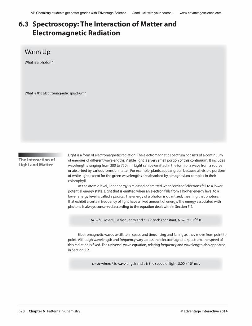
Light is a form of electromagnetic radiation. The electromagnetic spectrum consists of a continuum of energies of different wavelengths. Visible light is a very small portion of this continuum. It includes wavelengths ranging from 380 to 750 nm. Light can be emitted in the form of a wave from a source or absorbed by various forms of matter. For example, plants appear green because all visible portions of white light except for the green wavelengths are absorbed by a magnesium complex in their chlorophyll.
At the atomic level, light energy is released or emitted when “excited” electrons fall to a lower potential energy state. Light that is emitted when an electron falls from a higher energy level to a lower energy level is called a photon. The energy of a photon is quantized, meaning that photons that exhibit a certain frequency of light have a fixed amount of energy. The energy associated with photons is always conserved according to the equation dealt with in Section 5.2.
∆E = hν where ν is frequency and h is Planck’s constant, 6.626 x 10⁻³⁴ Js
Electromagnetic waves oscillate in space and time, rising and falling as they move from point to point. Although wavelength and frequency vary across the electromagnetic spectrum, the speed of this radiation is fixed. The universal wave equation, relating frequency and wavelength also appeared in Section 5.2.
c = λν where λ is wavelength and c is the speed of light, 3.00 x 10⁸ m/s
Warm UpWhat is a photon?
What is the electromagnetic spectrum?
AP Chemistry students get better grades with Edvantage Science. Good luck with your course! www.edvantagescience.com
© Edvantage Interactive 2014 Chapter 6 Patterns in Chemistry 329
������ ������ ������
�������������
��������� ������� ����� ������� ������� ���� ��� �����
�����������
������ ��� ��� ��
�������������������������������
���������������������
������������������������ ������������
������
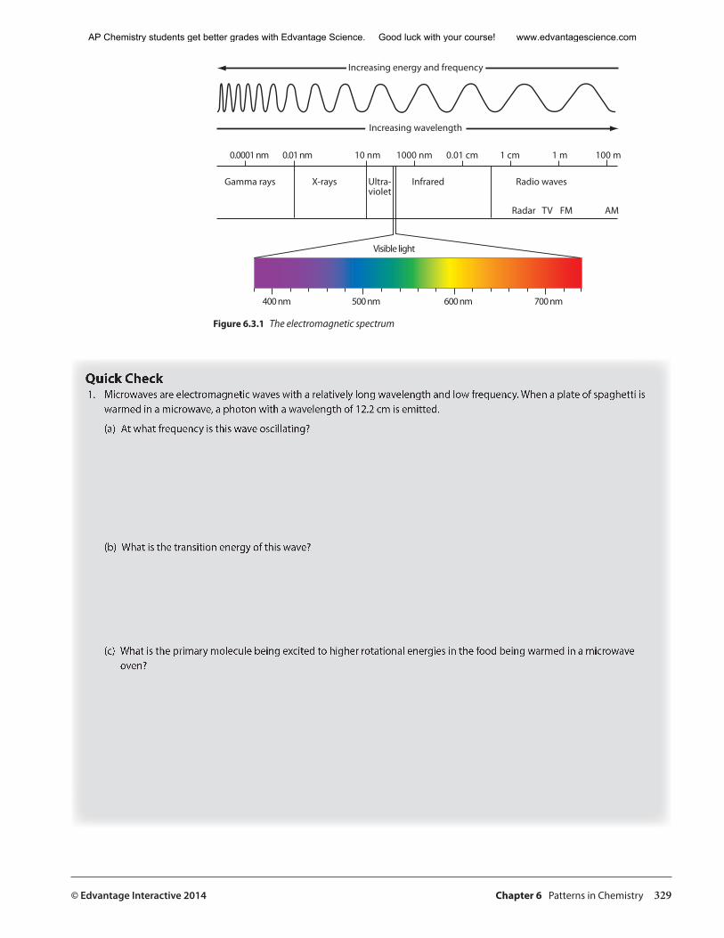
Figure 6.3.1 The electromagnetic spectrum
Quick Check 1. Microwaves are electromagnetic waves with a relatively long wavelength and low frequency. When a plate of spaghetti is
warmed in a microwave, a photon with a wavelength of 12.2 cm is emitted.
(a) At what frequency is this wave oscillating?
(b) What is the transition energy of this wave?
(c) What is the primary molecule being excited to higher rotational energies in the food being warmed in a microwave oven?
AP Chemistry students get better grades with Edvantage Science. Good luck with your course! www.edvantagescience.com

330 Chapter 6 Patterns in Chemistry © Edvantage Interactive 2014
SpectroscopyVarious regions of the electromagnetic spectrum may be used to help us probe matter with the assistance of a variety of different instruments in a process called spectroscopy We will look at the following types of spectroscopy below:• nuclear magnetic resonance• infrared spectroscopy• ultraviolet and visible-light spectroscopy• X-rays: photoelectron spectroscopy
Nuclear Magnetic Resonance
The longest waves in the electromagnetic spectrum are called radio waves. The wavelengths of such waves vary from just below a metre to infinity. As can be seen by applying the equation above, wavelength (λ) and frequency (ν) are reciprocally related. Since these waves have such long wavelengths, they oscillate at very low frequencies, from hundreds of megahertz down to tens of kilohertz. Superimposed on the pattern of these waves is a field of electromagnetic push-pull forces that is relatively low in energy. When radio frequency irradiation interacts with matter, there is no effect on electrons as their orbitals are separated by more energy than a radio wave can deliver. Radio waves cannot impact the position of the nucleus of an atom or the bonds in a molecule either. The matter continues to vibrate and rotate unchanged. Radio waves can, however, cause a change in nuclear spin. Nuclear spin is caused by the angular momentum of neutrons and protons and is analogous to electron spin as discussed in Section 5.5. The combination of spin and charge of the nucleus creates a magnetic moment. This means that a “nuclear magnet” behaves like a quantum mechanical compass needle that may align either up or down with an applied magnetic field. By placing the nuclei of a sample in a magnetic field and supplying just enough radio frequency energy to reorient the spins, each time a spin flips we observe a nuclear magnetic resonance (NMR). The internal magnetic fields within a molecule differ at each chemically distinct site.
Each signal (peak) or group of signals in an NMR spectrum is due to the nuclear spin change of a hydrogen atom in a distinct environment within a molecule.
An NMR spectrum can help reveal the structure of a molecule, by showing the bonding pattern. This is commonly used in the identification of organic compounds. For example, in organic compounds, NMR indicates whether a molecule contains carbon atoms that have one, two, or three hydrogen atoms attached, whether the molecule contains double or triple bonds or exists as a cis or trans isomer (see Section 8.1). Nuclear magnetic resonance imaging can even produce visual images of the human brain.
Analytical work typically involves connecting an NMR spectrometer to a computerized bank of spectra of millions of different compounds. The unknown compound can thus be compared with the spectra of millions of known standards. The analytical chemist can then quickly and accurately identify a sample.
The recognition of functional groups and other compound characteristics following the observation of an NMR spectrum is far beyond what is required in a course such as AP Chemistry. However, spectroscopy is interesting and it is important to be aware that many different types of spectroscopy exist and may be used to help us understand more about the structure and function of various types of matter.
AP Chemistry students get better grades with Edvantage Science. Good luck with your course! www.edvantagescience.com
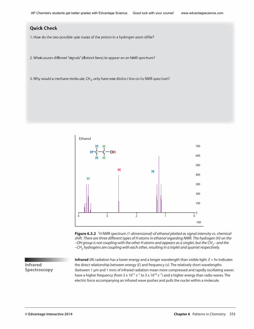
© Edvantage Interactive 2014 Chapter 6 Patterns in Chemistry 331
Quick Check
1. How do the two possible spin states of the proton in a hydrogen atom differ?
2. What causes different “signals” (distinct lines) to appear on an NMR spectrum?
3. Why would a methane molecule, CH4, only have one distinct line on its NMR spectrum?
���
���
���
���
���
���
���
�
����
� �� �� �� �� �
�
�
�
�
��
��� ��
�
�������
Figure 6.3.2 1H NMR spectrum (1-dimensional) of ethanol plotted as signal intensity vs. chemical shift. There are three different types of H atoms in ethanol regarding NMR. The hydrogen (H) on the –OH group is not coupling with the other H atoms and appears as a singlet, but the CH3– and the –CH2 hydrogens are coupling with each other, resulting in a triplet and quartet respectively.
Infrared Spectroscopy
Infrared (IR) radiation has a lower energy and a longer wavelength than visible light. E = hν indicates the direct relationship between energy (E) and frequency (ν). The relatively short wavelengths (between 1 µm and 1 mm) of infrared radiation mean more compressed and rapidly oscillating waves have a higher frequency (from 3 x 10¹¹ s–1 to 3 x 10¹⁴ s–1) and a higher energy than radio waves. The electric force accompanying an infrared wave pushes and pulls the nuclei within a molecule.
AP Chemistry students get better grades with Edvantage Science. Good luck with your course! www.edvantagescience.com
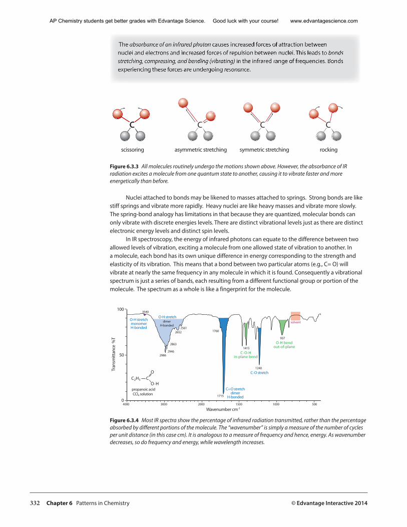
332 Chapter 6 Patterns in Chemistry © Edvantage Interactive 2014
The absorbance of an infrared photon causes increased forces of attraction between nuclei and electrons and increased forces of repulsion between nuclei. This leads to bonds stretching, compressing, and bending (vibrating) in the infrared range of frequencies. Bonds experiencing these forces are undergoing resonance.
�� �� �� �
���������� ��������������������� �������������������� �������
Figure 6.3.3 All molecules routinely undergo the motions shown above. However, the absorbance of IR radiation excites a molecule from one quantum state to another, causing it to vibrate faster and more energetically than before.
Nuclei attached to bonds may be likened to masses attached to springs. Strong bonds are like stiff springs and vibrate more rapidly. Heavy nuclei are like heavy masses and vibrate more slowly. The spring-bond analogy has limitations in that because they are quantized, molecular bonds can only vibrate with discrete energies levels. There are distinct vibrational levels just as there are distinct electronic energy levels and distinct spin levels.
In IR spectroscopy, the energy of infrared photons can equate to the difference between two allowed levels of vibration, exciting a molecule from one allowed state of vibration to another. In a molecule, each bond has its own unique difference in energy corresponding to the strength and elasticity of its vibration. This means that a bond between two particular atoms (e.g., C= O) will vibrate at nearly the same frequency in any molecule in which it is found. Consequently a vibrational spectrum is just a series of bands, each resulting from a different functional group or portion of the molecule. The spectrum as a whole is like a fingerprint for the molecule.
���
���� ���� ����
����
��������
����
��������
����
����
���
����
����
�������
���� ���� ���
��
�
���������������
����������������������������
�����������
���������������������������
���� ��
���������������
��������������
��������������
�����������
��������������������
������������������
����
�����
����
����
Figure 6.3.4 Most IR spectra show the percentage of infrared radiation transmitted, rather than the percentage absorbed by different portions of the molecule. The “wavenumber” is simply a measure of the number of cycles per unit distance (in this case cm). It is analogous to a measure of frequency and hence, energy. As wavenumber decreases, so do frequency and energy, while wavelength increases.
AP Chemistry students get better grades with Edvantage Science. Good luck with your course! www.edvantagescience.com
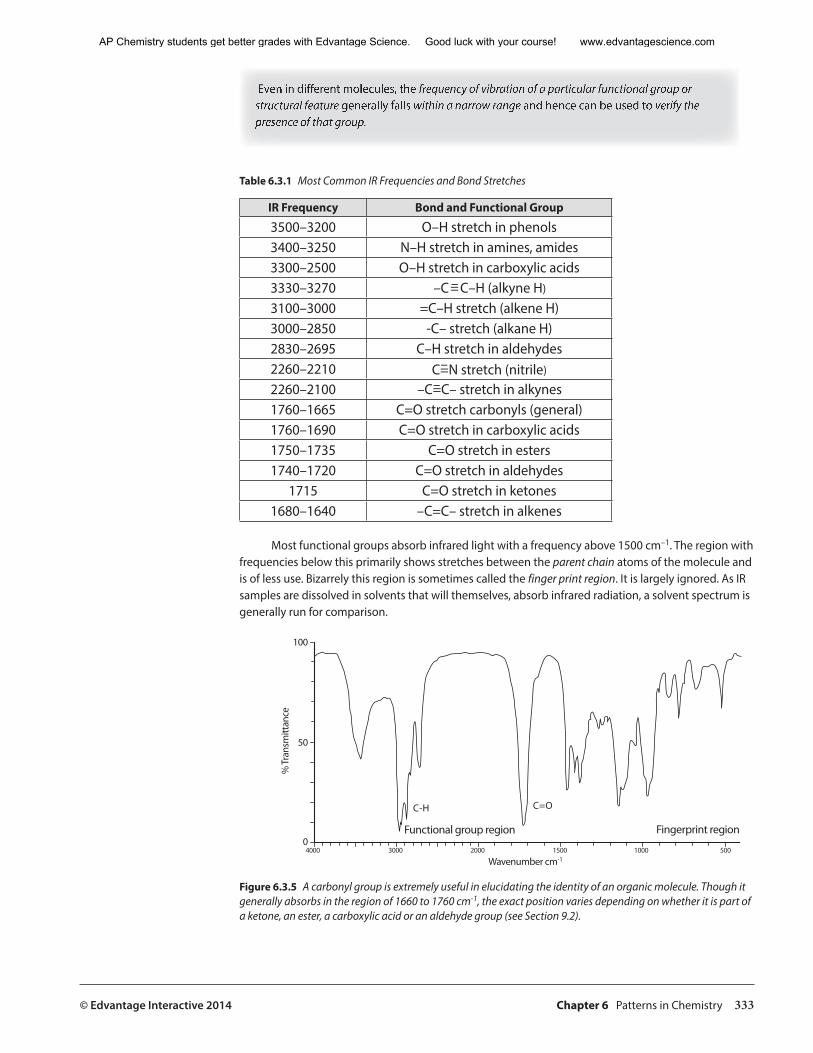
© Edvantage Interactive 2014 Chapter 6 Patterns in Chemistry 333
Even in different molecules, the frequency of vibration of a particular functional group or structural feature generally falls within a narrow range and hence can be used to verify the presence of that group.
Table 6.3.1 Most Common IR Frequencies and Bond Stretches
IR Frequency Bond and Functional Group
3500–3200 O–H stretch in phenols3400–3250 N–H stretch in amines, amides3300–2500 O–H stretch in carboxylic acids3330–3270 –C=C–H (alkyne H)
3100–3000 =C–H stretch (alkene H)3000–2850 -C– stretch (alkane H)2830–2695 C–H stretch in aldehydes2260–2210 C=N stretch (nitrile)
2260–2100 –C=C– stretch in alkynes1760–1665 C=O stretch carbonyls (general)1760–1690 C=O stretch in carboxylic acids1750–1735 C=O stretch in esters1740–1720 C=O stretch in aldehydes
1715 C=O stretch in ketones1680–1640 –C=C– stretch in alkenes
Most functional groups absorb infrared light with a frequency above 1500 cm–1. The region with frequencies below this primarily shows stretches between the parent chain atoms of the molecule and is of less use. Bizarrely this region is sometimes called the finger print region. It is largely ignored. As IR samples are dissolved in solvents that will themselves, absorb infrared radiation, a solvent spectrum is generally run for comparison.
���
���� ���� ���� ���� ���� ���
��
�
���������������
����������������������� ������������������
��� ���
�������
����
����
Figure 6.3.5 A carbonyl group is extremely useful in elucidating the identity of an organic molecule. Though it generally absorbs in the region of 1660 to 1760 cm-1, the exact position varies depending on whether it is part of a ketone, an ester, a carboxylic acid or an aldehyde group (see Section 9.2).
–
––
AP Chemistry students get better grades with Edvantage Science. Good luck with your course! www.edvantagescience.com

334 Chapter 6 Patterns in Chemistry © Edvantage Interactive 2014
Quick Check
1. What group might be indicated by the farthest left band in the IR spectrum in Figure 6.3.5?
2. Rank the following N to N bonds in order of increasing vibrational frequency: N-N, N=N, NΞN. Which will absorb infrared photons with the longest wavelength?
Ultraviolet and Visible-Light Spectroscopy
Visible and ultraviolet (UV) radiation are above infrared in terms of energy and below in terms of wavelength. Infrared radiation whose photon energies are below the red region of visible light gives way to visible red light at wavelengths between 800 and 700 nm. This is the region of the electromagnetic spectrum within which human beings perceive colour. The visible light portion of the spectrum extends from above 700 to just below 400 nm. The sum of all of these wavelengths makes up so-called white light. Wavelengths below 400 extending down to around 10 nm are associated with EMR (electromagnetic radiation) having energy above that of the violet portion of the visible range. For that reason, this portion of the spectrum is called ultraviolet. It is also the region within which photons may affect the most weakly held electrons, the so-called valence electrons. They may be excited out of their energy levels, and chemical bonding may be affected. The behaviour of these valence electrons is to a large extent governed by Coulomb’s law.
F =
kQ1Q2 r2
This relationship between the force (F) on two charged objects, the charges (Q1 and Q2), and the distance between them (r) was determined in 1785 by French physicist Charles-Augustin de Coulomb. The law is sometimes referred to as the inverse square law for obvious reasons, and it resembles Newton’s law of universal gravitation. The law shows that as the charge on one or both objects, such as a nucleus and an electron, increases, so does the force of attraction. It also shows that as the distance between an electron and the nucleus increases, the force of attraction decreases. This law can, and should (particularly in an AP course) be used to explain most of the atomic and ionic trends in the periodic table. This is a wonderful time to return to Section 6.2 and review those trends through the application of Coulomb’s law.
The valence electrons have the greatest r value and are screened most effectively from the charge on the nucleus. The reduced charge experienced by the valence electrons is sometimes referred to as Zeff or the effective nuclear charge. Z represents the atomic number, which is, effectively, the number of protons.
Zeff = Z – number of screening electrons
AP Chemistry students get better grades with Edvantage Science. Good luck with your course! www.edvantagescience.com
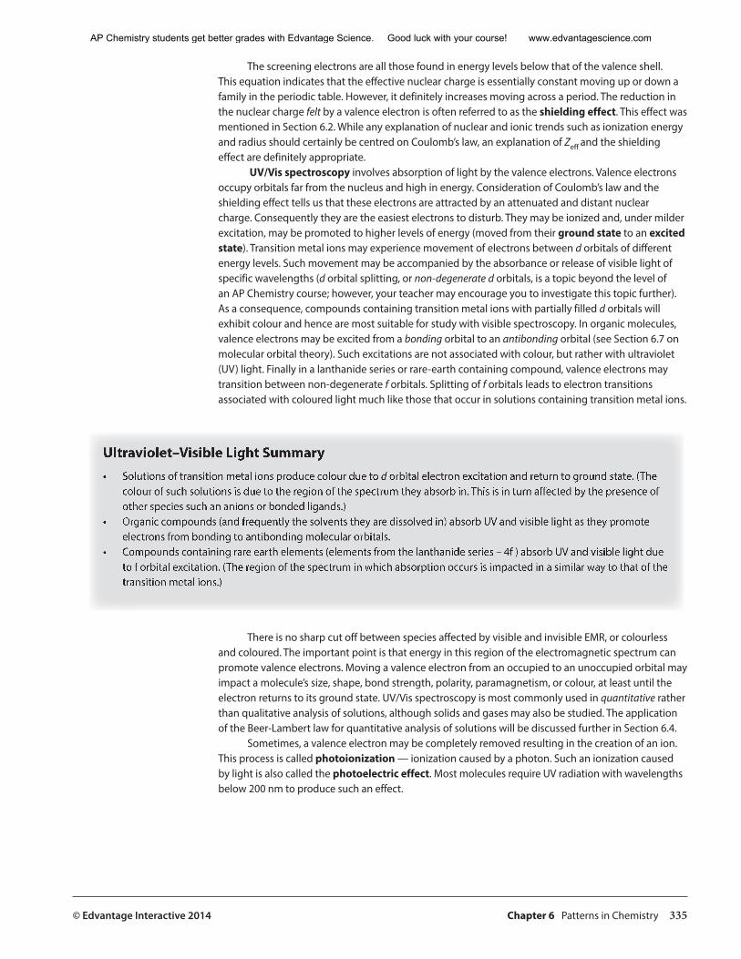
© Edvantage Interactive 2014 Chapter 6 Patterns in Chemistry 335
The screening electrons are all those found in energy levels below that of the valence shell. This equation indicates that the effective nuclear charge is essentially constant moving up or down a family in the periodic table. However, it definitely increases moving across a period. The reduction in the nuclear charge felt by a valence electron is often referred to as the shielding effect. This effect was mentioned in Section 6.2. While any explanation of nuclear and ionic trends such as ionization energy and radius should certainly be centred on Coulomb’s law, an explanation of Zeff and the shielding effect are definitely appropriate.
UV/Vis spectroscopy involves absorption of light by the valence electrons. Valence electrons occupy orbitals far from the nucleus and high in energy. Consideration of Coulomb’s law and the shielding effect tells us that these electrons are attracted by an attenuated and distant nuclear charge. Consequently they are the easiest electrons to disturb. They may be ionized and, under milder excitation, may be promoted to higher levels of energy (moved from their ground state to an excited state). Transition metal ions may experience movement of electrons between d orbitals of different energy levels. Such movement may be accompanied by the absorbance or release of visible light of specific wavelengths (d orbital splitting, or non-degenerate d orbitals, is a topic beyond the level of an AP Chemistry course; however, your teacher may encourage you to investigate this topic further). As a consequence, compounds containing transition metal ions with partially filled d orbitals will exhibit colour and hence are most suitable for study with visible spectroscopy. In organic molecules, valence electrons may be excited from a bonding orbital to an antibonding orbital (see Section 6.7 on molecular orbital theory). Such excitations are not associated with colour, but rather with ultraviolet (UV) light. Finally in a lanthanide series or rare-earth containing compound, valence electrons may transition between non-degenerate f orbitals. Splitting of f orbitals leads to electron transitions associated with coloured light much like those that occur in solutions containing transition metal ions.
Ultraviolet–Visible Light Summary• Solutions of transition metal ions produce colour due to d orbital electron excitation and return to ground state. (The
colour of such solutions is due to the region of the spectrum they absorb in. This is in turn affected by the presence of other species such an anions or bonded ligands.)
• Organic compounds (and frequently the solvents they are dissolved in) absorb UV and visible light as they promote electrons from bonding to antibonding molecular orbitals.
• Compounds containing rare earth elements (elements from the lanthanide series – 4f ) absorb UV and visible light due to f orbital excitation. (The region of the spectrum in which absorption occurs is impacted in a similar way to that of the transition metal ions.)
There is no sharp cut off between species affected by visible and invisible EMR, or colourless and coloured. The important point is that energy in this region of the electromagnetic spectrum can promote valence electrons. Moving a valence electron from an occupied to an unoccupied orbital may impact a molecule’s size, shape, bond strength, polarity, paramagnetism, or colour, at least until the electron returns to its ground state. UV/Vis spectroscopy is most commonly used in quantitative rather than qualitative analysis of solutions, although solids and gases may also be studied. The application of the Beer-Lambert law for quantitative analysis of solutions will be discussed further in Section 6.4.
Sometimes, a valence electron may be completely removed resulting in the creation of an ion. This process is called photoionization — ionization caused by a photon. Such an ionization caused by light is also called the photoelectric effect. Most molecules require UV radiation with wavelengths below 200 nm to produce such an effect.
AP Chemistry students get better grades with Edvantage Science. Good luck with your course! www.edvantagescience.com
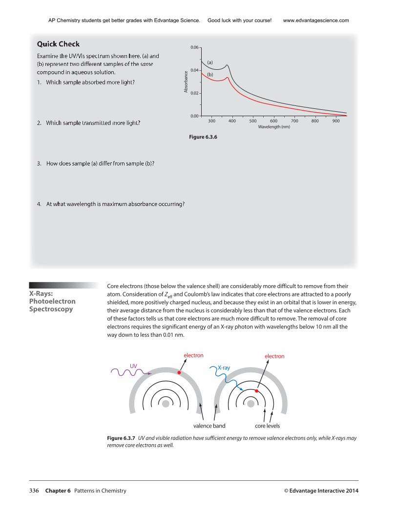
336 Chapter 6 Patterns in Chemistry © Edvantage Interactive 2014
Quick CheckExamine the UV/Vis spectrum shown here. (a) and (b) represent two different samples of the samecompound in aqueous solution.
1. Which sample absorbed more light?
2. Which sample transmitted more light?
3. How does sample (a) differ from sample (b)?
4. At what wavelength is maximum absorbance occurring?
����
����
����
����
���������������
���
����
���
� ���� ���� ���� ���� ���� ���� ���
���
���
Figure 6.3.6
X-Rays:PhotoelectronSpectroscopy
Core electrons (those below the valence shell) are considerably more difficult to remove from their atom. Consideration of Zeff and Coulomb’s law indicates that core electrons are attracted to a poorly shielded, more positively charged nucleus, and because they exist in an orbital that is lower in energy, their average distance from the nucleus is considerably less than that of the valence electrons. Each of these factors tells us that core electrons are much more difficult to remove. The removal of core electrons requires the significant energy of an X-ray photon with wavelengths below 10 nm all the way down to less than 0.01 nm.
������������ �����������
�������� ��������
�������
Figure 6.3.7 UV and visible radiation have sufficient energy to remove valence electrons only, while X-rays may remove core electrons as well.
AP Chemistry students get better grades with Edvantage Science. Good luck with your course! www.edvantagescience.com
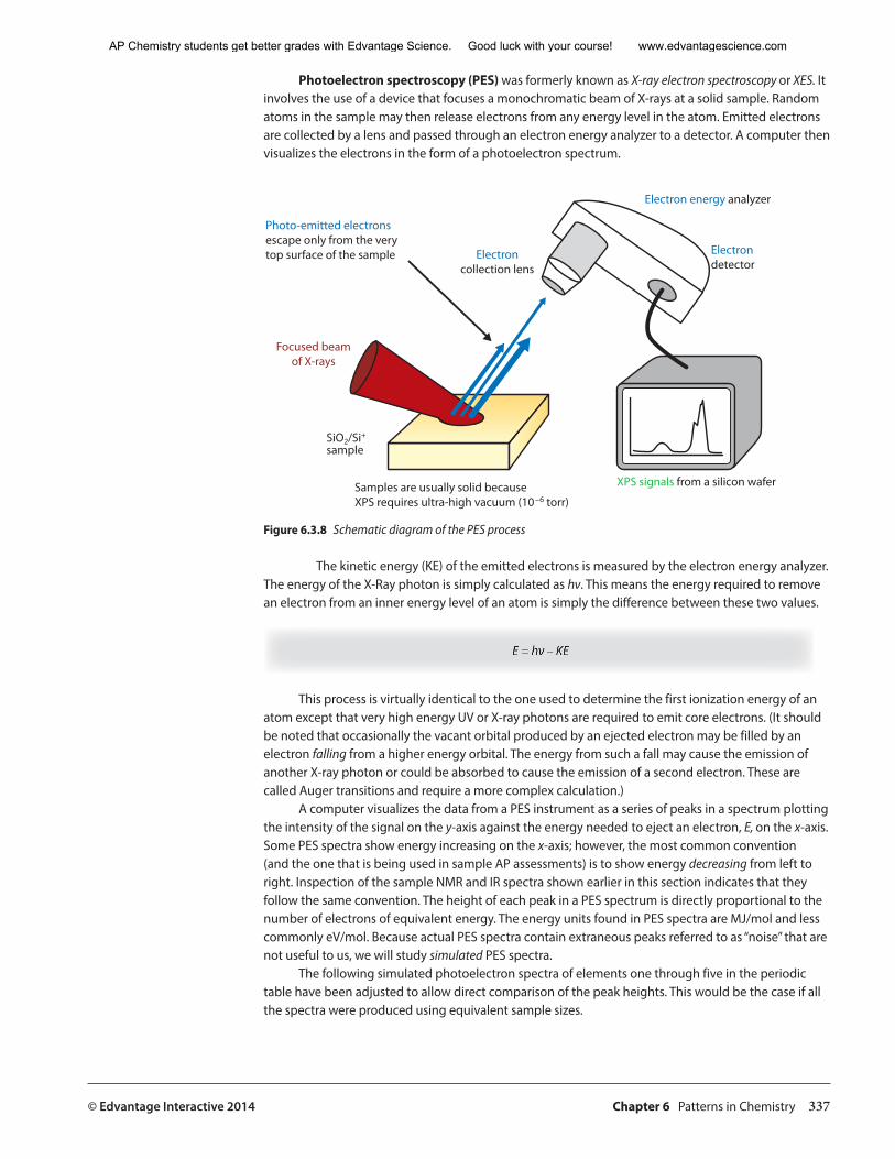
© Edvantage Interactive 2014 Chapter 6 Patterns in Chemistry 337
Photoelectron spectroscopy (PES) was formerly known as X-ray electron spectroscopy or XES. It involves the use of a device that focuses a monochromatic beam of X-rays at a solid sample. Random atoms in the sample may then release electrons from any energy level in the atom. Emitted electrons are collected by a lens and passed through an electron energy analyzer to a detector. A computer then visualizes the electrons in the form of a photoelectron spectrum.
���������������������������������������������������������������������������
���������������������������������������������������������������������������
��������������
��������������������������������
�����������������������
���������������������
������������������������
�����������������
Figure 6.3.8 Schematic diagram of the PES process
The kinetic energy (KE) of the emitted electrons is measured by the electron energy analyzer. The energy of the X-Ray photon is simply calculated as hν. This means the energy required to remove an electron from an inner energy level of an atom is simply the difference between these two values.
E = hν – KE
This process is virtually identical to the one used to determine the first ionization energy of an atom except that very high energy UV or X-ray photons are required to emit core electrons. (It should be noted that occasionally the vacant orbital produced by an ejected electron may be filled by an electron falling from a higher energy orbital. The energy from such a fall may cause the emission of another X-ray photon or could be absorbed to cause the emission of a second electron. These are called Auger transitions and require a more complex calculation.)
A computer visualizes the data from a PES instrument as a series of peaks in a spectrum plotting the intensity of the signal on the y-axis against the energy needed to eject an electron, E, on the x-axis. Some PES spectra show energy increasing on the x-axis; however, the most common convention (and the one that is being used in sample AP assessments) is to show energy decreasing from left to right. Inspection of the sample NMR and IR spectra shown earlier in this section indicates that they follow the same convention. The height of each peak in a PES spectrum is directly proportional to the number of electrons of equivalent energy. The energy units found in PES spectra are MJ/mol and less commonly eV/mol. Because actual PES spectra contain extraneous peaks referred to as “noise” that are not useful to us, we will study simulated PES spectra.
The following simulated photoelectron spectra of elements one through five in the periodic table have been adjusted to allow direct comparison of the peak heights. This would be the case if all the spectra were produced using equivalent sample sizes.
AP Chemistry students get better grades with Edvantage Science. Good luck with your course! www.edvantagescience.com
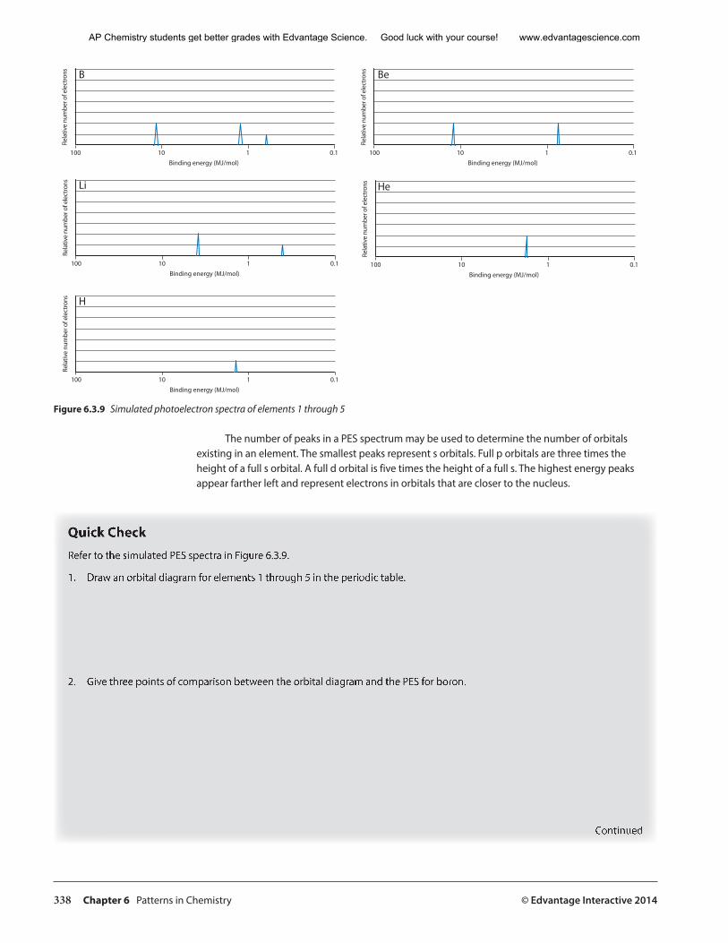
338 Chapter 6 Patterns in Chemistry © Edvantage Interactive 2014
�����������������������
�������
����
���
������
������
��
� ���� ��� �� ���
�����������������������
�������
����
���
������
������
��
� ���� ��� �� ���
�����������������������
�������
����
���
������
������
��
� ���� ��� �� ���
�����������������������
�������
����
���
������
������
��
� ���� ��� �� ���
�����������������������
�������
����
���
������
������
��
� ���� ��� �� ���
B Be
Li He
H
Figure 6.3.9 Simulated photoelectron spectra of elements 1 through 5
The number of peaks in a PES spectrum may be used to determine the number of orbitals existing in an element. The smallest peaks represent s orbitals. Full p orbitals are three times the height of a full s orbital. A full d orbital is five times the height of a full s. The highest energy peaks appear farther left and represent electrons in orbitals that are closer to the nucleus.
Quick Check Refer to the simulated PES spectra in Figure 6.3.9.
1. Draw an orbital diagram for elements 1 through 5 in the periodic table.
2. Give three points of comparison between the orbital diagram and the PES for boron.
Continued
AP Chemistry students get better grades with Edvantage Science. Good luck with your course! www.edvantagescience.com
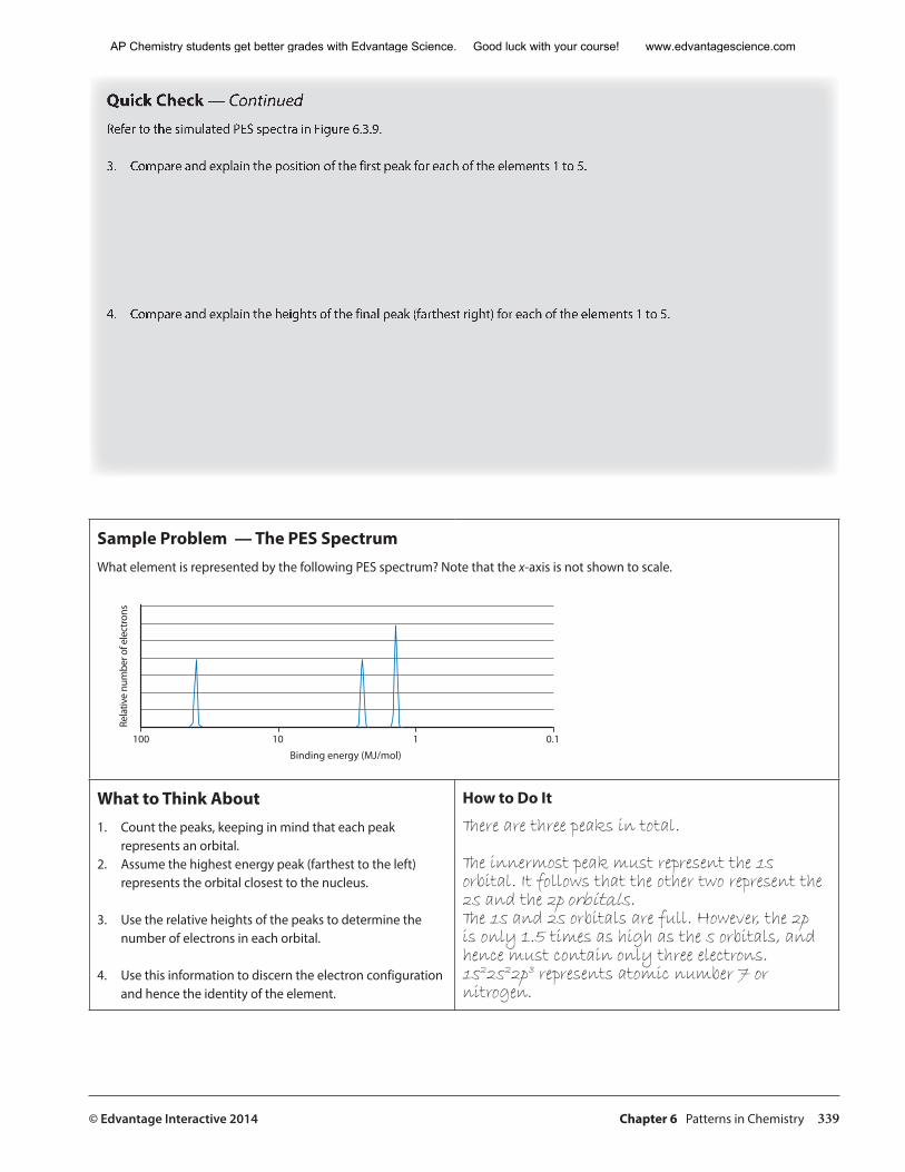
© Edvantage Interactive 2014 Chapter 6 Patterns in Chemistry 339
Quick Check — Continued Refer to the simulated PES spectra in Figure 6.3.9.
3. Compare and explain the position of the first peak for each of the elements 1 to 5.
4. Compare and explain the heights of the final peak (farthest right) for each of the elements 1 to 5.
Sample Problem — The PES SpectrumWhat element is represented by the following PES spectrum? Note that the x-axis is not shown to scale.
�����������������������
�������
����
���
������
������
��
� ���� ��� �� ���
What to Think About1. Count the peaks, keeping in mind that each peak
represents an orbital.2. Assume the highest energy peak (farthest to the left)
represents the orbital closest to the nucleus.
3. Use the relative heights of the peaks to determine the number of electrons in each orbital.
4. Use this information to discern the electron configuration and hence the identity of the element.
How to Do It
There are three peaks in total.
The innermost peak must represent the 1s orbital. It follows that the other two represent the 2s and the 2p orbitals.The 1s and 2s orbitals are full. However, the 2p is only 1.5 times as high as the s orbitals, and hence must contain only three electrons.1s22s22p3 represents atomic number 7 or nitrogen.
AP Chemistry students get better grades with Edvantage Science. Good luck with your course! www.edvantagescience.com
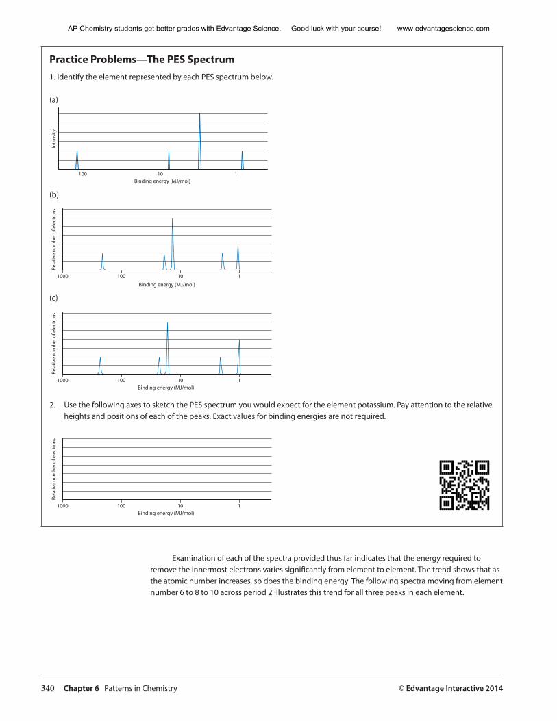
340 Chapter 6 Patterns in Chemistry © Edvantage Interactive 2014
Practice Problems—The PES Spectrum 1. Identify the element represented by each PES spectrum below.
(a)
�����������������������
������
���
� ���� ��� �
(b)
�������
����
���
������
������
��
� ����� ���� ��� �
�����������������������
(c)
�����������������������
�������
����
���
������
������
��
� ����� ���� ��� �
2. Use the following axes to sketch the PES spectrum you would expect for the element potassium. Pay attention to the relative heights and positions of each of the peaks. Exact values for binding energies are not required.
�����������������������
�������
����
���
������
������
��
� ����� ���� ��� �
Examination of each of the spectra provided thus far indicates that the energy required to remove the innermost electrons varies significantly from element to element. The trend shows that as the atomic number increases, so does the binding energy. The following spectra moving from element number 6 to 8 to 10 across period 2 illustrates this trend for all three peaks in each element.
AP Chemistry students get better grades with Edvantage Science. Good luck with your course! www.edvantagescience.com
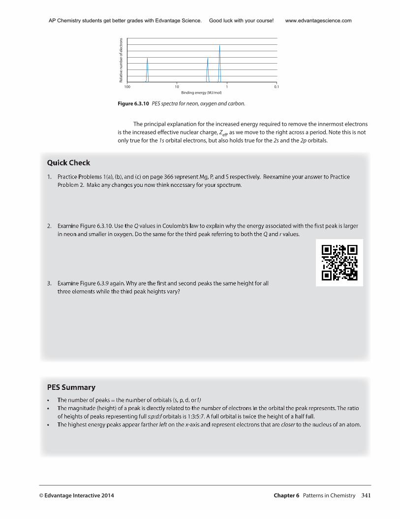
© Edvantage Interactive 2014 Chapter 6 Patterns in Chemistry 341
�����������������������
�������
����
���
������
������
��
� ���� ��� �� ���
Figure 6.3.10 PES spectra for neon, oxygen and carbon.
The principal explanation for the increased energy required to remove the innermost electrons is the increased effective nuclear charge, Zeff, as we move to the right across a period. Note this is not only true for the 1s orbital electrons, but also holds true for the 2s and the 2p orbitals.
Quick Check
1. Practice Problems 1(a), (b), and (c) on page 366 represent Mg, P, and S respectively. Reexamine your answer to Practice Problem 2. Make any changes you now think necessary for your spectrum.
2. Examine Figure 6.3.10. Use the Q values in Coulomb’s law to explain why the energy associated with the first peak is larger in neon and smaller in oxygen. Do the same for the third peak referring to both the Q and r values.
3. Examine Figure 6.3.9 again. Why are the first and second peaks the same height for all three elements while the third peak heights vary?
PES Summary• The number of peaks = the number of orbitals (s, p, d, or f)• The magnitude (height) of a peak is directly related to the number of electrons in the orbital the peak represents. The ratio
of heights of peaks representing full s:p:d:f orbitals is 1:3:5:7. A full orbital is twice the height of a half full.• The highest energy peaks appear farther left on the x-axis and represent electrons that are closer to the nucleus of an atom.
AP Chemistry students get better grades with Edvantage Science. Good luck with your course! www.edvantagescience.com
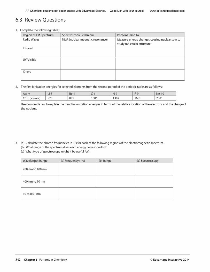
342 Chapter 6 Patterns in Chemistry © Edvantage Interactive 2014
6.3 Review Questions
1. Complete the following table:
Region of EM Spectrum Spectroscopic Technique Photons Used ToRadio Waves NMR (nuclear magnetic resonance) Measure energy changes causing nuclear spin to
study molecular structure.Infrared
UV/Visible
X-rays
2. The first ionization energies for selected elements from the second period of the periodic table are as follows:
Atom Li-3 Be-4 C-6 N-7 F-9 Ne-101st IE (kJ/mol) 520 899 1086 1302 1681 2081
Use Coulomb’s law to explain the trend in ionization energies in terms of the relative location of the electrons and the charge of the nucleus.
3. (a) Calculate the photon frequencies in 1/s for each of the following regions of the electromagnetic spectrum.(b) What range of the spectrum does each energy correspond to?(c) What type of spectroscopy might it be useful for?
Wavelength Range (a) Frequency (1/s) (b) Range (c) Spectroscopy
700 nm to 400 nm
400 nm to 10 nm
10 to 0.01 nm
AP Chemistry students get better grades with Edvantage Science. Good luck with your course! www.edvantagescience.com
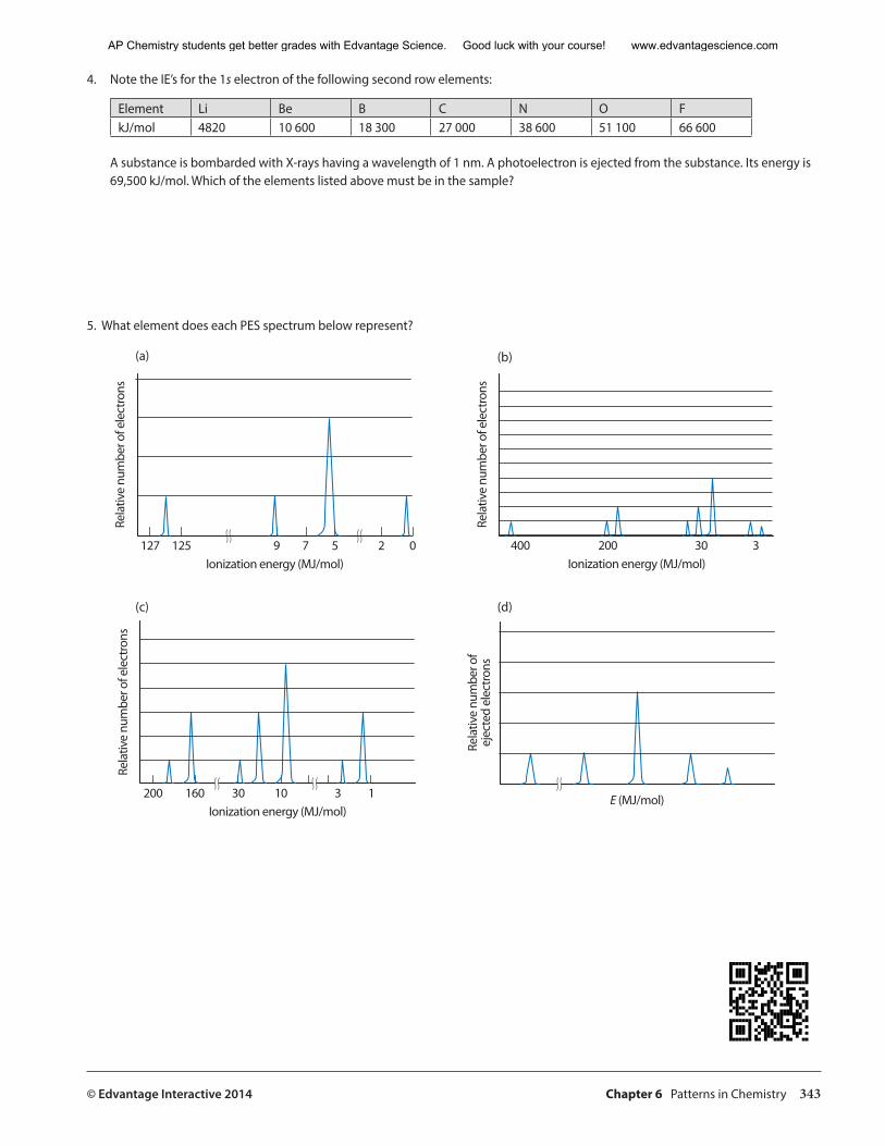
© Edvantage Interactive 2014 Chapter 6 Patterns in Chemistry 343
4. Note the IE’s for the 1s electron of the following second row elements:
Element Li Be B C N O FkJ/mol 4820 10 600 18 300 27 000 38 600 51 100 66 600
A substance is bombarded with X-rays having a wavelength of 1 nm. A photoelectron is ejected from the substance. Its energy is 69,500 kJ/mol. Which of the elements listed above must be in the sample?
5. What element does each PES spectrum below represent?
��������������������������
�������
����
���
������
������
��
� ���� ���� �� �� �� �� ���������������������������
�������
����
���
������
������
��
� ���� ���� ��� �
��������������������������
�������
����
���
������
������
��
� ���� ���� ��� ��� �� � ����������
�������
����
���
�����
����
��������
����
�
(b)(a)
(d)(c)
AP Chemistry students get better grades with Edvantage Science. Good luck with your course! www.edvantagescience.com
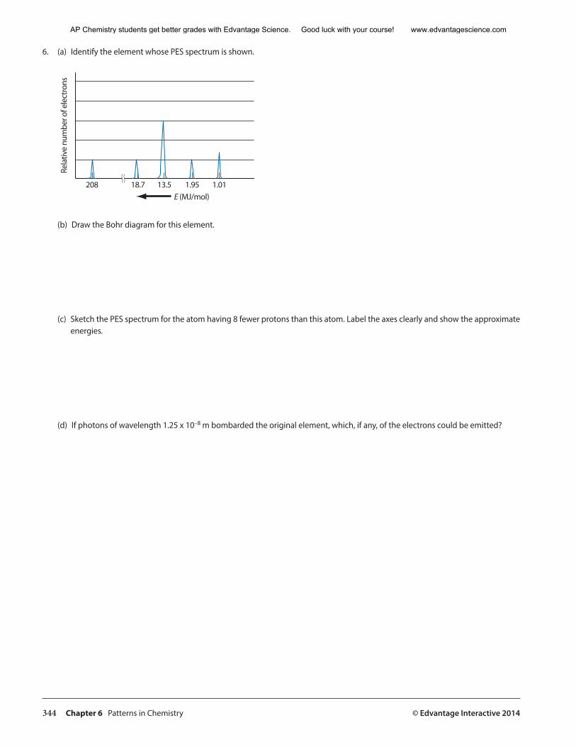
344 Chapter 6 Patterns in Chemistry © Edvantage Interactive 2014
6. (a) Identify the element whose PES spectrum is shown.
����������
�������
����
���
������
������
��
� ���� ����� ����� ����� ����
(b) Draw the Bohr diagram for this element.
(c) Sketch the PES spectrum for the atom having 8 fewer protons than this atom. Label the axes clearly and show the approximate energies.
(d) If photons of wavelength 1.25 x 10⁻⁸ m bombarded the original element, which, if any, of the electrons could be emitted?
AP Chemistry students get better grades with Edvantage Science. Good luck with your course! www.edvantagescience.com
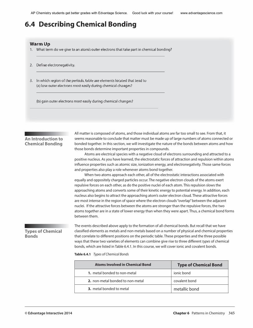
© Edvantage Interactive 2014 Chapter 6 Patterns in Chemistry 345
6.4 Describing Chemical Bonding
Warm Up 1. What term do we give to an atom’s outer electrons that take part in chemical bonding?
____________________________________________________________________
2. Define electronegativity.____________________________________________________________________
3. In which region of the periodic table are elements located that tend to (a) lose outer electrons most easily during chemical changes?____________________________________________________________________
(b) gain outer electrons most easily during chemical changes?____________________________________________________________________
An Introduction to Chemical Bonding
All matter is composed of atoms, and those individual atoms are far too small to see. From that, it seems reasonable to conclude that matter must be made up of large numbers of atoms connected or bonded together. In this section, we will investigate the nature of the bonds between atoms and how those bonds determine important properties in compounds.
Atoms are electrical species with a negative cloud of electrons surrounding and attracted to a positive nucleus. As you have learned, the electrostatic forces of attraction and repulsion within atoms influence properties such as atomic size, ionization energy, and electronegativity. Those same forces and properties also play a role whenever atoms bond together.
When two atoms approach each other, all of the electrostatic interactions associated with equally and oppositely charged particles occur. The negative electron clouds of the atoms exert repulsive forces on each other, as do the positive nuclei of each atom. This repulsion slows the approaching atoms and converts some of their kinetic energy to potential energy. In addition, each nucleus also begins to attract the approaching atom’s outer electron cloud. These attractive forces are most intense in the region of space where the electron clouds “overlap” between the adjacent nuclei. If the attractive forces between the atoms are stronger than the repulsive forces, the two atoms together are in a state of lower energy than when they were apart. Thus, a chemical bond forms between them.
Types of Chemical Bonds
The events described above apply to the formation of all chemical bonds. But recall that we have classified elements as metals and non-metals based on a number of physical and chemical properties that correlate to different positions on the periodic table. These properties and the three possible ways that these two varieties of elements can combine give rise to three different types of chemical bonds, which are listed in Table 6.4.1. In this course, we will cover ionic and covalent bonds.
Table 6.4.1 Types of Chemical Bonds
Atoms Involved in Chemical Bond Type of Chemical Bond
1. metal bonded to non-metal ionic bond
2. non-metal bonded to non-metal covalent bond
3. metal bonded to metal metallic bond
AP Chemistry students get better grades with Edvantage Science. Good luck with your course! www.edvantagescience.com
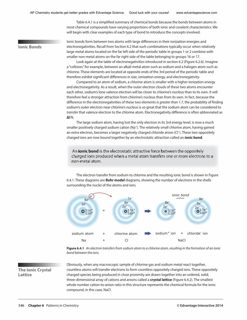
346 Chapter 6 Patterns in Chemistry © Edvantage Interactive 2014
Table 6.4.1 is a simplified summary of chemical bonds because the bonds between atoms in most chemical compounds have varying proportions of both ionic and covalent characteristics. We will begin with clear examples of each type of bond to introduce the concepts involved.
Ionic BondsIonic bonds form between two atoms with large differences in their ionization energies and electronegativities. Recall from Section 6.2 that such combinations typically occur when relatively large metal atoms located on the far left side of the periodic table in groups 1 or 2 combine with smaller non-metal atoms on the far right side of the table belonging to groups 16 or 17.
Look again at the table of electronegativities introduced in section 6.2 (Figure 6.2.6). Imagine a “collision,” for example, between an alkali metal atom such as sodium and a halogen atom such as chlorine. These elements are located at opposite ends of the 3rd period of the periodic table and therefore exhibit significant differences in size, ionization energy, and electronegativity.
Compared to an atom of sodium, a chlorine atom is smaller with a higher ionization energy and electronegativity. As a result, when the outer electron clouds of these two atoms encounter each other, sodium’s lone valence electron will be closer to chlorine’s nucleus than to its own. It will therefore feel a stronger attraction from chlorine’s nucleus than from its own. In fact, because the difference in the electronegativities of these two elements is greater than 1.7, the probability of finding sodium’s outer electron near chlorine’s nucleus is so great that the sodium atom can be considered to transfer that valence electron to the chlorine atom. Electronegativity difference is often abbreviated as ∆EN.
The large sodium atom, having lost the only electron in its 3rd energy level, is now a much smaller positively charged sodium cation (Na+). The relatively small chlorine atom, having gained an extra electron, becomes a larger negatively charged chloride anion (Cl–). These two oppositely charged ions are now bound together by an electrostatic attraction called an ionic bond.
An ionic bond is the electrostatic attractive force between the oppositely charged ions produced when a metal atom transfers one or more electrons to a non-metal atom.
The electron transfer from sodium to chlorine and the resulting ionic bond is shown in Figure 6.4.1. These diagrams are Bohr model diagrams, showing the number of electrons in the shells surrounding the nuclei of the atoms and ions.
2e-8e-
e-
11p+
12n0+
2e-8e-
7e-
17p+
18n0
2e-8e-
11p+
12n0
2e-8e-
8e-
17p+
18n0
ionic bond
+
+
+sodium atom chlorine atom sodium+ ion chloride- ion
Na Cl NaCl
Figure 6.4.1 An electron transfers from sodium atom to a chlorine atom, resulting in the formation of an ionic bond between the ions.
The Ionic Crystal Lattice
Obviously, when any macroscopic sample of chlorine gas and sodium metal react together, countless atoms will transfer electrons to form countless oppositely charged ions. These oppositely charged species being produced in close proximity are drawn together into an ordered, solid, three-dimensional array of cations and anions called a crystal lattice (Figure 6.4.2). The smallest whole number cation-to-anion ratio in this structure represents the chemical formula for the ionic compound, in this case, NaCl.
AP Chemistry students get better grades with Edvantage Science. Good luck with your course! www.edvantagescience.com
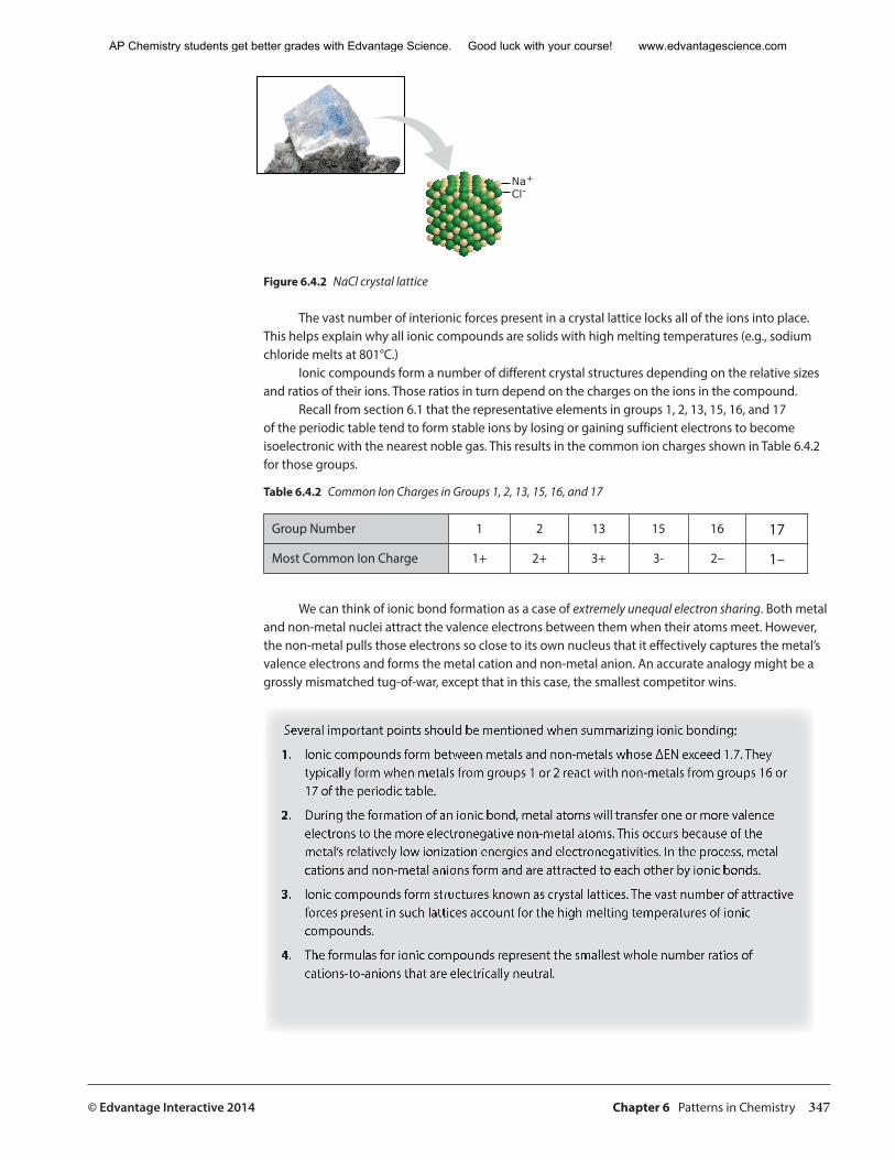
© Edvantage Interactive 2014 Chapter 6 Patterns in Chemistry 347
Na+Cl-
Figure 6.4.2 NaCl crystal lattice
The vast number of interionic forces present in a crystal lattice locks all of the ions into place. This helps explain why all ionic compounds are solids with high melting temperatures (e.g., sodium chloride melts at 801°C.)
Ionic compounds form a number of different crystal structures depending on the relative sizes and ratios of their ions. Those ratios in turn depend on the charges on the ions in the compound.
Recall from section 6.1 that the representative elements in groups 1, 2, 13, 15, 16, and 17 of the periodic table tend to form stable ions by losing or gaining sufficient electrons to become isoelectronic with the nearest noble gas. This results in the common ion charges shown in Table 6.4.2 for those groups.
Table 6.4.2 Common Ion Charges in Groups 1, 2, 13, 15, 16, and 17
Group Number 1 2 13 15 16 17
Most Common Ion Charge 1+ 2+ 3+ 3- 2– 1–
We can think of ionic bond formation as a case of extremely unequal electron sharing. Both metal and non-metal nuclei attract the valence electrons between them when their atoms meet. However, the non-metal pulls those electrons so close to its own nucleus that it effectively captures the metal’s valence electrons and forms the metal cation and non-metal anion. An accurate analogy might be a grossly mismatched tug-of-war, except that in this case, the smallest competitor wins.
Several important points should be mentioned when summarizing ionic bonding:
1. Ionic compounds form between metals and non-metals whose ∆EN exceed 1.7. They typically form when metals from groups 1 or 2 react with non-metals from groups 16 or 17 of the periodic table.
2. During the formation of an ionic bond, metal atoms will transfer one or more valence electrons to the more electronegative non-metal atoms. This occurs because of the metal’s relatively low ionization energies and electronegativities. In the process, metal cations and non-metal anions form and are attracted to each other by ionic bonds.
3. Ionic compounds form structures known as crystal lattices. The vast number of attractive forces present in such lattices account for the high melting temperatures of ionic compounds.
4. The formulas for ionic compounds represent the smallest whole number ratios of cations-to-anions that are electrically neutral.
AP Chemistry students get better grades with Edvantage Science. Good luck with your course! www.edvantagescience.com
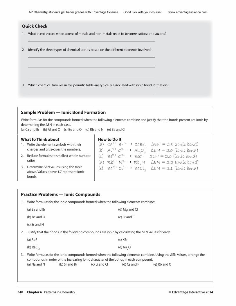
348 Chapter 6 Patterns in Chemistry © Edvantage Interactive 2014
Quick Check1. What event occurs when atoms of metals and non-metals react to become cations and anions?
________________________________________________________________________
2. Identify the three types of chemical bonds based on the different elements involved.
________________________________________________________________________
________________________________________________________________________
________________________________________________________________________
3. Which chemical families in the periodic table are typically associated with ionic bond formation?
________________________________________________________________________
Sample Problem — Ionic Bond FormationWrite formulas for the compounds formed when the following elements combine and justify that the bonds present are ionic by determining the ∆EN in each case.(a) Ca and Br (b) Al and O (c) Be and O (d) Rb and N (e) Ba and Cl
What to Think about1. Write the element symbols with their
charges and criss-cross the numbers.
2. Reduce formulas to smallest whole number ratios
3. Determine ∆EN values using the table above. Values above 1.7 represent ionic bonds.
How to Do It(a) Ca2+ Br1– ➝ CaBr2 ∆EN = 1.8 (ionic bond)(b) Al3+ O2– ➝ Al2O3 ∆EN = 2.0 (ionic bond)(c) Be2+ O2– ➝ BeO ∆EN = 2.0 (ionic bond)(d) Rb1+ N3– ➝ Rb3N ∆EN = 2.2 (ionic bond)(e) Ba2+ Cl1– ➝ BaCl2 ∆EN = 2.1 (ionic bond)
Practice Problems — Ionic Compounds1. Write formulas for the ionic compounds formed when the following elements combine:
(a) Ba and Br (d) Mg and Cl
(b) Be and O (e) Fr and F
(c) Sr and N
2. Justify that the bonds in the following compounds are ionic by calculating the ∆EN values for each.
(a) RbF (c) KBr
(b) RaCl2 (d) Na2O
3. Write formulas for the ionic compounds formed when the following elements combine. Using the ∆EN values, arrange the compounds in order of the increasing ionic character of the bonds in each compound.(a) Na and N (b) Sr and Br (c) Li and Cl (d) Cs and F (e) Rb and O
AP Chemistry students get better grades with Edvantage Science. Good luck with your course! www.edvantagescience.com
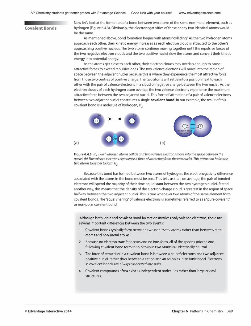
© Edvantage Interactive 2014 Chapter 6 Patterns in Chemistry 349
Covalent BondsNow let’s look at the formation of a bond between two atoms of the same non-metal element, such as hydrogen (Figure 6.4.3). Obviously, the electronegativities of these or any two identical atoms would be the same.
As mentioned above, bond formation begins with atoms “colliding.” As the two hydrogen atoms approach each other, their kinetic energy increases as each electron cloud is attracted to the other’s approaching positive nucleus. The two atoms continue moving together until the repulsive forces of the two negative electron clouds and the two positive nuclei slow the atoms and convert their kinetic energy into potential energy.
As the atoms get close to each other, their electron clouds may overlap enough to cause attractive forces to exceed repulsive ones. The two valence electrons will move into the region of space between the adjacent nuclei because this is where they experience the most attractive force from those two centres of positive charge. The two atoms will settle into a position next to each other with the pair of valence electrons in a cloud of negative charge between the two nuclei. As the electron clouds of each hydrogen atom overlap, the two valence electrons experience the maximum attractive force between the two adjacent nuclei. This force of attraction of a pair of valence electrons between two adjacent nuclei constitutes a single covalent bond. In our example, the result of this covalent bond is a molecule of hydrogen, H2
+1
1e
+1
1e
+1 +12e(a) (b)
+ +electron cloud
(negative)
Figure 6.4.3 (a) Two hydrogen atoms collide and two valence electrons move into the space between the nuclei. (b) The valence electrons experience a force of attraction from the two nuclei. This attraction holds the two atoms together to form H2.
Because this bond has formed between two atoms of hydrogen, the electronegativity difference associated with the atoms in the bond must be zero. This tells us that, on average, the pair of bonded electrons will spend the majority of their time equidistant between the two hydrogen nuclei. Stated another way, this means that the density of the electron charge cloud is greatest in the region of space halfway between the two adjacent nuclei. This is true whenever two atoms of the same element form covalent bonds. The “equal sharing” of valence electrons is sometimes referred to as a “pure covalent” or non-polar covalent bond.
Although both ionic and covalent bond formation involves only valence electrons, there are several important differences between the two events:
1. Covalent bonds typically form between two non-metal atoms rather than between metal atoms and non-metal atoms.
2. Because no electron transfer occurs and no ions form, all of the species prior to and following covalent bond formation between two atoms are electrically neutral.
3. The force of attraction in a covalent bond is between a pair of electrons and two adjacent positive nuclei, rather than between a cation and an anion as in an ionic bond. Electrons in covalent bonds are always associated into pairs.
4. Covalent compounds often exist as independent molecules rather than large crystal structures.
AP Chemistry students get better grades with Edvantage Science. Good luck with your course! www.edvantagescience.com
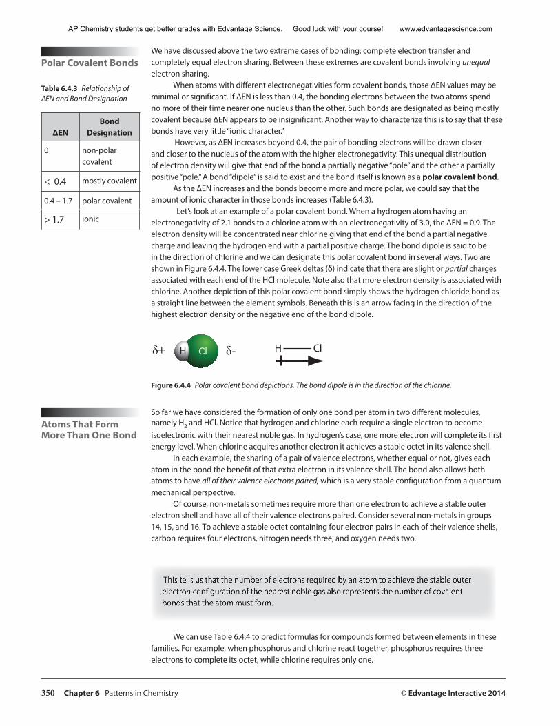
350 Chapter 6 Patterns in Chemistry © Edvantage Interactive 2014
Polar Covalent Bonds
We have discussed above the two extreme cases of bonding: complete electron transfer and completely equal electron sharing. Between these extremes are covalent bonds involving unequal electron sharing.
When atoms with different electronegativities form covalent bonds, those ∆EN values may be minimal or significant. If ∆EN is less than 0.4, the bonding electrons between the two atoms spend no more of their time nearer one nucleus than the other. Such bonds are designated as being mostly covalent because ∆EN appears to be insignificant. Another way to characterize this is to say that these bonds have very little “ionic character.”
However, as ∆EN increases beyond 0.4, the pair of bonding electrons will be drawn closer and closer to the nucleus of the atom with the higher electronegativity. This unequal distribution of electron density will give that end of the bond a partially negative “pole” and the other a partially positive “pole.” A bond “dipole” is said to exist and the bond itself is known as a polar covalent bond.
As the ∆EN increases and the bonds become more and more polar, we could say that the amount of ionic character in those bonds increases (Table 6.4.3).
Let’s look at an example of a polar covalent bond. When a hydrogen atom having an electronegativity of 2.1 bonds to a chlorine atom with an electronegativity of 3.0, the ∆EN = 0.9. The electron density will be concentrated near chlorine giving that end of the bond a partial negative charge and leaving the hydrogen end with a partial positive charge. The bond dipole is said to be in the direction of chlorine and we can designate this polar covalent bond in several ways. Two are shown in Figure 6.4.4. The lower case Greek deltas (δ) indicate that there are slight or partial charges associated with each end of the HCl molecule. Note also that more electron density is associated with chlorine. Another depiction of this polar covalent bond simply shows the hydrogen chloride bond as a straight line between the element symbols. Beneath this is an arrow facing in the direction of the highest electron density or the negative end of the bond dipole.
ClH�+ �� � ��
Atoms That Form More Than One Bond
Figure 6.4.4 Polar covalent bond depictions. The bond dipole is in the direction of the chlorine.
So far we have considered the formation of only one bond per atom in two different molecules, namely H2 and HCl. Notice that hydrogen and chlorine each require a single electron to become isoelectronic with their nearest noble gas. In hydrogen’s case, one more electron will complete its first energy level. When chlorine acquires another electron it achieves a stable octet in its valence shell.
In each example, the sharing of a pair of valence electrons, whether equal or not, gives each atom in the bond the benefit of that extra electron in its valence shell. The bond also allows both atoms to have all of their valence electrons paired, which is a very stable configuration from a quantum mechanical perspective.
Of course, non-metals sometimes require more than one electron to achieve a stable outer electron shell and have all of their valence electrons paired. Consider several non-metals in groups 14, 15, and 16. To achieve a stable octet containing four electron pairs in each of their valence shells, carbon requires four electrons, nitrogen needs three, and oxygen needs two.
This tells us that the number of electrons required by an atom to achieve the stable outer electron configuration of the nearest noble gas also represents the number of covalent bonds that the atom must form.
We can use Table 6.4.4 to predict formulas for compounds formed between elements in these families. For example, when phosphorus and chlorine react together, phosphorus requires three electrons to complete its octet, while chlorine requires only one.
∆ENBond
Designation
0 non-polar covalent
< 0.4 mostly covalent
0.4 – 1.7 polar covalent
> 1.7 ionic
Table 6.4.3 Relationship of ∆EN and Bond Designation
AP Chemistry students get better grades with Edvantage Science. Good luck with your course! www.edvantagescience.com
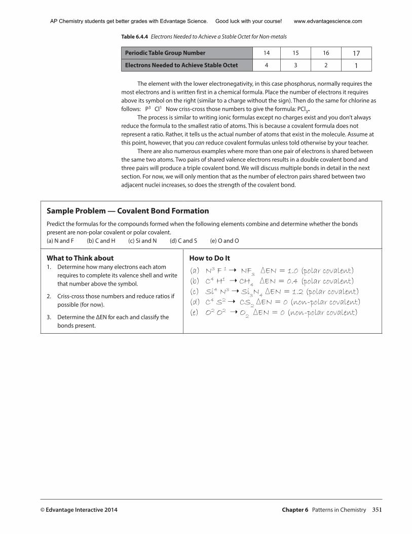
© Edvantage Interactive 2014 Chapter 6 Patterns in Chemistry 351
Table 6.4.4 Electrons Needed to Achieve a Stable Octet for Non-metals
Periodic Table Group Number 14 15 16 17
Electrons Needed to Achieve Stable Octet 4 3 2 1
The element with the lower electronegativity, in this case phosphorus, normally requires the most electrons and is written first in a chemical formula. Place the number of electrons it requires above its symbol on the right (similar to a charge without the sign). Then do the same for chlorine as follows: P3 Cl1 Now criss-cross those numbers to give the formula: PCl3.
The process is similar to writing ionic formulas except no charges exist and you don’t always reduce the formula to the smallest ratio of atoms. This is because a covalent formula does not represent a ratio. Rather, it tells us the actual number of atoms that exist in the molecule. Assume at this point, however, that you can reduce covalent formulas unless told otherwise by your teacher.
There are also numerous examples where more than one pair of electrons is shared between the same two atoms. Two pairs of shared valence electrons results in a double covalent bond and three pairs will produce a triple covalent bond. We will discuss multiple bonds in detail in the next section. For now, we will only mention that as the number of electron pairs shared between two adjacent nuclei increases, so does the strength of the covalent bond.
Sample Problem — Covalent Bond FormationPredict the formulas for the compounds formed when the following elements combine and determine whether the bonds present are non-polar covalent or polar covalent.(a) N and F (b) C and H (c) Si and N (d) C and S (e) O and O
What to Think about1. Determine how many electrons each atom
requires to complete its valence shell and write that number above the symbol.
2. Criss-cross those numbers and reduce ratios if possible (for now).
3. Determine the ∆EN for each and classify the bonds present.
How to Do It
(a) N3 F 1 ➝ NF3 ∆EN = 1.0 (polar covalent)(b) C4 H1 ➝ CH4 ∆EN = 0.4 (polar covalent) (c) Si4 N3 ➝ Si3N4 ∆EN = 1.2 (polar covalent)(d) C4 S2 ➝ CS2 ∆EN = 0 (non-polar covalent)(e) O2 O2 ➝ O2 ∆EN = 0 (non-polar covalent)
AP Chemistry students get better grades with Edvantage Science. Good luck with your course! www.edvantagescience.com
352 Chapter 6 Patterns in Chemistry © Edvantage Interactive 2014
Practice Problems — Comparing Types of Chemical Bonds1. Consider the ∆EN values and pair up the elements Al, Cl, N, and Na to write the formula for the types of compounds identified
below. Justify each choice by showing the appropriate ∆EN value next to each formula. (a) A compound with an ionic bond
(b) A compound with a polar covalent bond
(c) A compound with a non-polar covalent bond
2. Calculate the ∆EN values for the bonds in the following compounds. Then arrange the compounds in order from those containing bonds in which the electrons are shared most equally to those in which the electrons are shared most unequally.
(a) H2O (b) PCl3 (c) CI4 (d) SiO2 (e) AlN
3. Complete the following table:
Elements Present Formula ∆EN ValueNature of
BondsAtom Possessing Greater
Electron Density
C and S
B and Cl
Al and O
N and I
Ca and F
The Strength of Ionic vs. Covalent Bonds
Remember that ionic compounds are solids at room temperature and have high melting points. This results from the vast number of interionic forces locking all of the ions together in place in the crystal lattice. As mentioned earlier, the common ionic compound NaCl melts at 801°C.
Covalent compounds, however, usually exist as individual molecules and in any of the three states of matter: solid, liquid, or gas. We shouldn’t conclude from this, however, that covalent bonds are any weaker than ionic bonds. Consider, for example, the molecule methane, CH4, the main component of natural gas.
Although the melting point of methane (–182°C) is very low compared to sodium chloride, this physical property does not reflect the strength of the C – H bonds in methane or indicate that the bonds are weak compared to those in NaCl.
This is because no chemical bonds are broken when methane or any molecular covalent compound melts. Instead, weak intermolecular forces between the molecules are overcome. The result is that molecules are separated from each other rather than breaking the bonds between the atoms within those molecules.
The energy required to separate the bonded carbon and hydrogen atoms within the molecules from each other is far more than that required to simply pull the molecules apart. In the final section
AP Chemistry students get better grades with Edvantage Science. Good luck with your course! www.edvantagescience.com
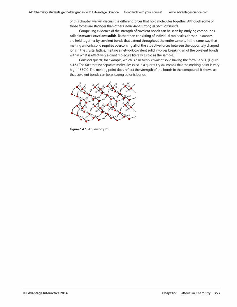
© Edvantage Interactive 2014 Chapter 6 Patterns in Chemistry 353
of this chapter, we will discuss the different forces that hold molecules together. Although some of those forces are stronger than others, none are as strong as chemical bonds.
Compelling evidence of the strength of covalent bonds can be seen by studying compounds called network covalent solids. Rather than consisting of individual molecules, these substances are held together by covalent bonds that extend throughout the entire sample. In the same way that melting an ionic solid requires overcoming all of the attractive forces between the oppositely charged ions in the crystal lattice, melting a network covalent solid involves breaking all of the covalent bonds within what is effectively a giant molecule literally as big as the sample.
Consider quartz, for example, which is a network covalent solid having the formula SiO2 (Figure 6.4.5). The fact that no separate molecules exist in a quartz crystal means that the melting point is very high: 1550°C. The melting point does reflect the strength of the bonds in the compound. It shows us that covalent bonds can be as strong as ionic bonds.
Figure 6.4.5 A quartz crystal
AP Chemistry students get better grades with Edvantage Science. Good luck with your course! www.edvantagescience.com
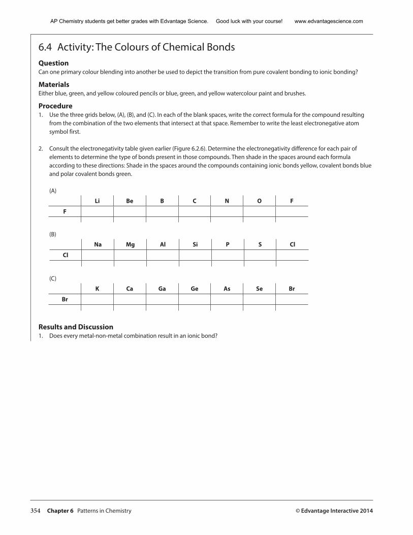
354 Chapter 6 Patterns in Chemistry © Edvantage Interactive 2014
6.4 Activity: The Colours of Chemical Bonds QuestionCan one primary colour blending into another be used to depict the transition from pure covalent bonding to ionic bonding?
MaterialsEither blue, green, and yellow coloured pencils or blue, green, and yellow watercolour paint and brushes.
Procedure1. Use the three grids below, (A), (B), and (C). In each of the blank spaces, write the correct formula for the compound resulting
from the combination of the two elements that intersect at that space. Remember to write the least electronegative atom symbol first.
2. Consult the electronegativity table given earlier (Figure 6.2.6). Determine the electronegativity difference for each pair of elements to determine the type of bonds present in those compounds. Then shade in the spaces around each formula according to these directions: Shade in the spaces around the compounds containing ionic bonds yellow, covalent bonds blue and polar covalent bonds green.
(A)
Li Be B C N O F
F
(B)
Na Mg Al Si P S Cl
Cl
(C)
K Ca Ga Ge As Se Br
Br
Results and Discussion1. Does every metal-non-metal combination result in an ionic bond?
AP Chemistry students get better grades with Edvantage Science. Good luck with your course! www.edvantagescience.com
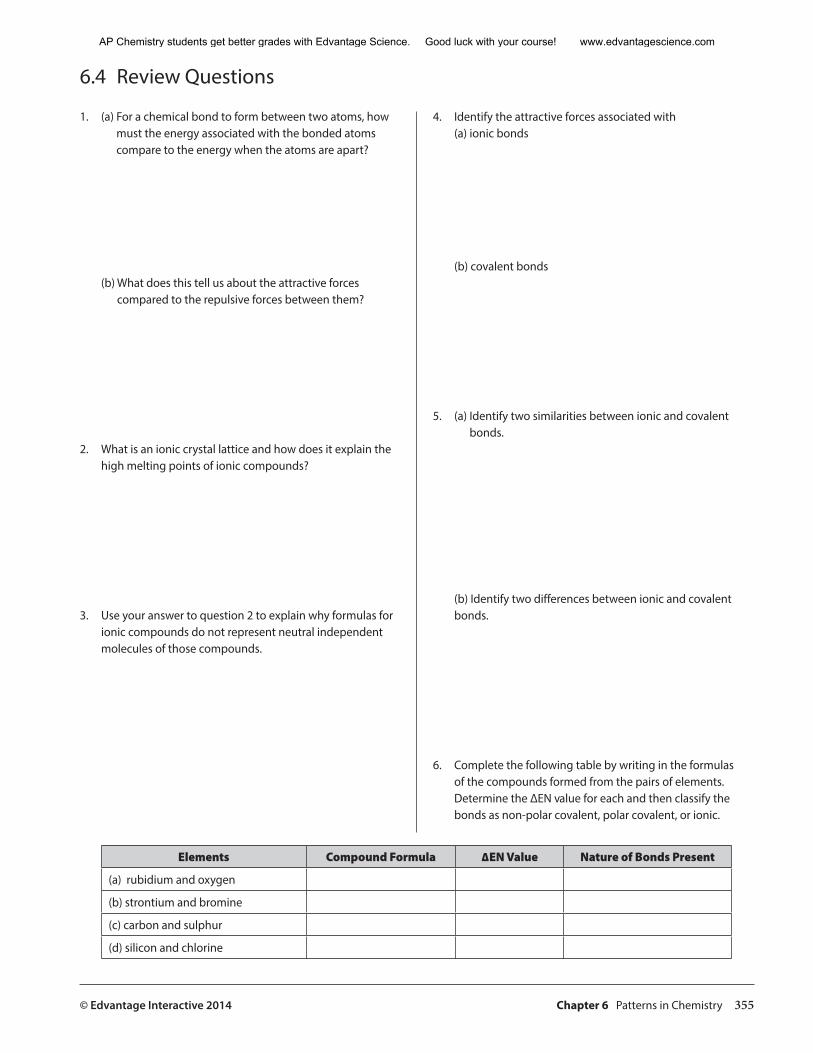
© Edvantage Interactive 2014 Chapter 6 Patterns in Chemistry 355
6.4 Review Questions
1. (a) For a chemical bond to form between two atoms, how must the energy associated with the bonded atoms compare to the energy when the atoms are apart?
(b) What does this tell us about the attractive forces compared to the repulsive forces between them?
2. What is an ionic crystal lattice and how does it explain the high melting points of ionic compounds?
3. Use your answer to question 2 to explain why formulas for ionic compounds do not represent neutral independent molecules of those compounds.
4. Identify the attractive forces associated with (a) ionic bonds
(b) covalent bonds
5. (a) Identify two similarities between ionic and covalent bonds.
(b) Identify two differences between ionic and covalent bonds.
6. Complete the following table by writing in the formulas of the compounds formed from the pairs of elements. Determine the ∆EN value for each and then classify the bonds as non-polar covalent, polar covalent, or ionic.
Elements Compound Formula ∆EN Value Nature of Bonds Present
(a) rubidium and oxygen
(b) strontium and bromine
(c) carbon and sulphur
(d) silicon and chlorine
AP Chemistry students get better grades with Edvantage Science. Good luck with your course! www.edvantagescience.com
356 Chapter 6 Patterns in Chemistry © Edvantage Interactive 2014
7. Magnesium is a metal and sulphur is a non-metal. Compare the ∆EN value for these elements in the compound MgS to the ∆EN value for the non-metals hydrogen and oxygen in water, H2O. Which of the two compounds possesses a greater amount of ionic character in its bonds?
8. Glucose is a covalent compound with the molecular formula C6H12O6. This and many other covalent formulas aren’t reduced to the smallest whole-number ratios of atoms in the compound. Why not?
9. Many covalent compounds have much lower melting points than ionic compounds. Why does this not mean that covalent bonds are weaker than ionic bonds?
10. Diamond is a form of pure carbon containing only covalent bonds. It is the hardest substance known and has a melting point of about 3550°C. What name do we give to this type of covalent substance? Suggest a reason for its very high melting point.
11. Consider the nature of the covalent bonds present in HCl and in N2. Which substance would you expect to have the higher melting point? Give a reason for your answer.
AP Chemistry students get better grades with Edvantage Science. Good luck with your course! www.edvantagescience.com
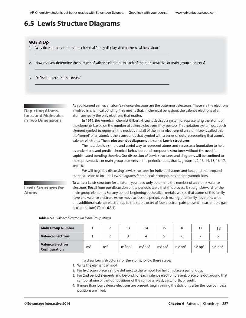
© Edvantage Interactive 2014 Chapter 6 Patterns in Chemistry 357
6.5 Lewis Structure Diagrams
Warm Up1. Why do elements in the same chemical family display similar chemical behaviour?
_________________________________________________________________________
2. How can you determine the number of valence electrons in each of the representative or main group elements?_________________________________________________________________________
3. Define the term “stable octet.”_________________________________________________________________________
Depicting Atoms, Ions, and Molecules in Two Dimensions
As you learned earlier, an atom’s valence electrons are the outermost electrons. These are the electrons involved in chemical bonding. This means that, in chemical behaviour, the valence electrons of an atom are really the only electrons that matter.
In 1916, the American chemist Gilbert N. Lewis devised a system of representing the atoms of the elements based on the number of valence electrons they possess. This notation system uses each element symbol to represent the nucleus and all of the inner electrons of an atom (Lewis called this the “kernel” of an atom). It then surrounds that symbol with a series of dots representing that atom’s valence electrons. These electron dot diagrams are called Lewis structures.
The notation is a simple and useful way to represent atoms and serves as a foundation to help us understand and predict chemical behaviours and compound structures without the need for sophisticated bonding theories. Our discussion of Lewis structures and diagrams will be confined to the representative or main group elements in the periodic table, that is, groups 1, 2, 13, 14, 15, 16, 17, and 18.
We will begin by discussing Lewis structures for individual atoms and ions, and then expand that discussion to include Lewis diagrams for molecular compounds and polyatomic ions.
Lewis Structures for Atoms
To write a Lewis structure for an atom, you need only determine the number of an atom’s valence electrons. Recall from our discussion of the periodic table that this process is straightforward for the main group elements. For any period, beginning at the alkali metals, we see that atoms of this family have one valence electron. As we move across the period, each main group family has atoms with one additional valence electron up to the stable octet of four electron pairs present in each noble gas (except helium) (Table 6.5.1).
Table 6.5.1 Valence Electrons in Main Group Atoms
Main Group Number 1 2 13 14 15 16 17 18
Valence Electrons 1 2 3 4 5 6 7 8
Valence Electron Configuration
ns1 ns2 ns2 np1 ns2 np2 ns2 np3 ns2 np4 ns2 np5 ns2 np6
To draw Lewis structures for the atoms, follow these steps:1. Write the element symbol.2. For hydrogen place a single dot next to the symbol. For helium place a pair of dots.3. For 2nd period elements and beyond: for each valence electron present, place one dot around that
symbol at one of the four positions of the compass: west, east, north, or south. 4. If more than four valence electrons are present, begin pairing the dots only after the four compass
positions are filled.
AP Chemistry students get better grades with Edvantage Science. Good luck with your course! www.edvantagescience.com
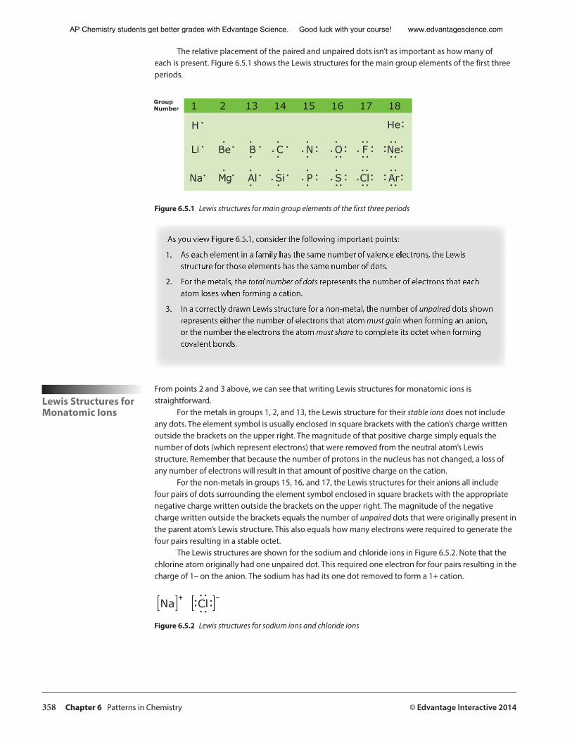
358 Chapter 6 Patterns in Chemistry © Edvantage Interactive 2014
The relative placement of the paired and unpaired dots isn’t as important as how many of each is present. Figure 6.5.1 shows the Lewis structures for the main group elements of the first three periods.
GroupNumber 1
HeH
Li
Na
Be
Mg
B
Al
C
Si
N
P
O
S
F
Cl Ar
Ne
2 13 14 15 16 17 18
Figure 6.5.1 Lewis structures for main group elements of the first three periods
As you view Figure 6.5.1, consider the following important points:
1. As each element in a family has the same number of valence electrons, the Lewis structure for those elements has the same number of dots.
2. For the metals, the total number of dots represents the number of electrons that each atom loses when forming a cation.
3. In a correctly drawn Lewis structure for a non-metal, the number of unpaired dots shown represents either the number of electrons that atom must gain when forming an anion, or the number the electrons the atom must share to complete its octet when forming covalent bonds.
Lewis Structures for Monatomic Ions
From points 2 and 3 above, we can see that writing Lewis structures for monatomic ions is straightforward.
For the metals in groups 1, 2, and 13, the Lewis structure for their stable ions does not include any dots. The element symbol is usually enclosed in square brackets with the cation’s charge written outside the brackets on the upper right. The magnitude of that positive charge simply equals the number of dots (which represent electrons) that were removed from the neutral atom’s Lewis structure. Remember that because the number of protons in the nucleus has not changed, a loss of any number of electrons will result in that amount of positive charge on the cation.
For the non-metals in groups 15, 16, and 17, the Lewis structures for their anions all include four pairs of dots surrounding the element symbol enclosed in square brackets with the appropriate negative charge written outside the brackets on the upper right. The magnitude of the negative charge written outside the brackets equals the number of unpaired dots that were originally present in the parent atom’s Lewis structure. This also equals how many electrons were required to generate the four pairs resulting in a stable octet.
The Lewis structures are shown for the sodium and chloride ions in Figure 6.5.2. Note that the chlorine atom originally had one unpaired dot. This required one electron for four pairs resulting in the charge of 1– on the anion. The sodium has had its one dot removed to form a 1+ cation.
Na Cl� �
Figure 6.5.2 Lewis structures for sodium ions and chloride ions
AP Chemistry students get better grades with Edvantage Science. Good luck with your course! www.edvantagescience.com
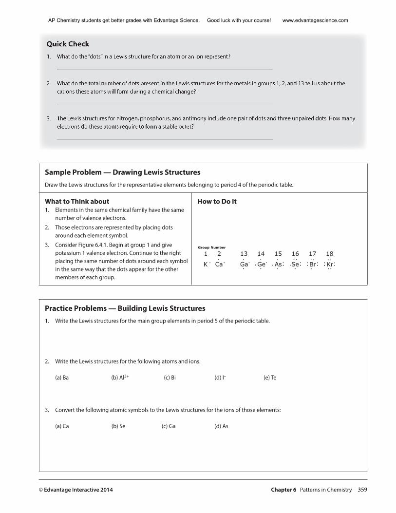
© Edvantage Interactive 2014 Chapter 6 Patterns in Chemistry 359
Quick Check1. What do the “dots” in a Lewis structure for an atom or an ion represent?
_________________________________________________________________________
2. What do the total number of dots present in the Lewis structures for the metals in groups 1, 2, and 13 tell us about the cations these atoms will form during a chemical change?
_________________________________________________________________________
3. The Lewis structures for nitrogen, phosphorus, and antimony include one pair of dots and three unpaired dots. How many electrons do these atoms require to form a stable octet?
_________________________________________________________________________
Sample Problem — Drawing Lewis StructuresDraw the Lewis structures for the representative elements belonging to period 4 of the periodic table.
What to Think about1. Elements in the same chemical family have the same
number of valence electrons.
2. Those electrons are represented by placing dots around each element symbol.
3. Consider Figure 6.4.1. Begin at group 1 and give potassium 1 valence electron. Continue to the right placing the same number of dots around each symbol in the same way that the dots appear for the other members of each group.
How to Do It
Group Number
1
K Ca Ga As Kr
2 13 14 15 16 17 18
Ge Se Br
Practice Problems — Building Lewis Structures1. Write the Lewis structures for the main group elements in period 5 of the periodic table.
2. Write the Lewis structures for the following atoms and ions.
(a) Ba (b) Al3+ (c) Bi (d) I– (e) Te
3. Convert the following atomic symbols to the Lewis structures for the ions of those elements:
(a) Ca (b) Se (c) Ga (d) As
AP Chemistry students get better grades with Edvantage Science. Good luck with your course! www.edvantagescience.com
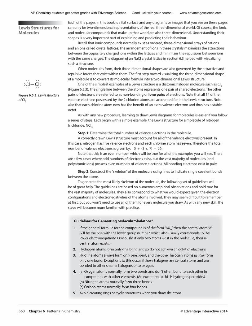
360 Chapter 6 Patterns in Chemistry © Edvantage Interactive 2014
Lewis Structures for Molecules
Each of the pages in this book is a flat surface and any diagrams or images that you see on these pages can only be two-dimensional representations of the real three-dimensional world. Of course, the ionic and molecular compounds that make up that world are also three-dimensional. Understanding their shapes is a very important part of explaining and predicting their behaviour.
Recall that ionic compounds normally exist as ordered, three-dimensional arrays of cations and anions called crystal lattices. The arrangement of ions in these crystals maximizes the attractions between the oppositely charged ions within the lattices and minimizes the repulsions between ions with the same charges. The diagram of an NaCl crystal lattice in section 6.3 helped with visualizing such a structure.
When molecules form, their three-dimensional shapes are also governed by the attractive and repulsive forces that exist within them. The first step toward visualizing the three-dimensional shape of a molecule is to convert its molecular formula into a two-dimensional Lewis structure.
One of the simplest examples of a Lewis structure is a diatomic halogen molecule such as Cl2 (Figure 6.5.3). The single line between the atoms represents one pair of shared electrons. The other pairs of electrons are referred to as non-bonding or lone pairs of electrons. Note that all 14 of the valence electrons possessed by the 2 chlorine atoms are accounted for in the Lewis structure. Note also that each chlorine atom now has the benefit of an extra valence electron and thus has a stable octet.
As with any new procedure, learning to draw Lewis diagrams for molecules is easier if you follow a series of steps. Let’s begin with a simple example: the Lewis structure for a molecule of nitrogen trichloride, NCl3.
Step 1: Determine the total number of valence electrons in the molecule. A correctly drawn Lewis structure must account for all of the valence electrons present. In
this case, nitrogen has five valence electrons and each chlorine atom has seven. Therefore the total number of valence electrons is given by: 5 + (3 x 7) = 26.
Note that this is an even number, which will be true for all of the examples you will see. There are a few cases where odd numbers of electrons exist, but the vast majority of molecules (and polyatomic ions) possess even numbers of valence electrons. All bonding electrons exist in pairs.
Step 2: Construct the “skeleton” of the molecule using lines to indicate single covalent bonds between the atoms.
To generate the most likely skeleton of the molecule, the following set of guidelines will be of great help. The guidelines are based on numerous empirical observations and hold true for the vast majority of molecules. They also correspond to what we would expect given the electron configurations and electronegativities of the atoms involved. They may seem difficult to remember at first, but you won’t need to use all of them for every molecule you draw. As with any new skill, the steps will become more familiar with practice.
Guidelines for Generating Molecule “Skeletons”
1. If the general formula for the compound is of the form “AXn,” then the central atom “A” will be the one with the lower group number, which also usually corresponds to the lower electronegativity. Obviously, if only two atoms exist in the molecule, then no central atom exists.
2. Hydrogen atoms form only one bond and so do not achieve an octet of electrons.
3. Fluorine atoms always form only one bond, and the other halogen atoms usually form only one bond. Exceptions to this occur if those halogens are central atoms and are bonded to other smaller halogens or to oxygen.
4. (a) Oxygen atoms normally form two bonds and don’t often bond to each other in compounds with other elements. (An exception to this is hydrogen peroxide.)
(b) Nitrogen atoms normally form three bonds.(c) Carbon atoms normally form four bonds.
5. Avoid creating rings or cyclic structures when you draw skeletons.
Cl Cl
Figure 6.5.3 Lewis structure of Cl2
AP Chemistry students get better grades with Edvantage Science. Good luck with your course! www.edvantagescience.com
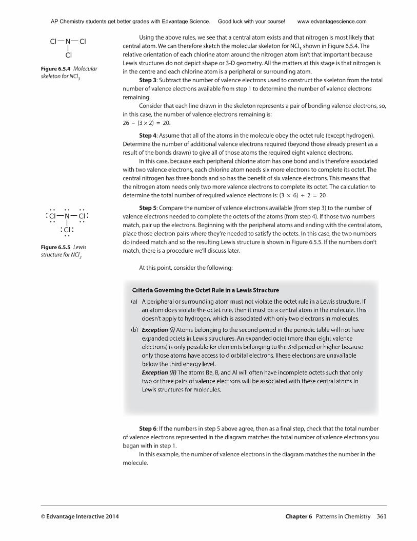
© Edvantage Interactive 2014 Chapter 6 Patterns in Chemistry 361
Using the above rules, we see that a central atom exists and that nitrogen is most likely that central atom. We can therefore sketch the molecular skeleton for NCl3 shown in Figure 6.5.4. The relative orientation of each chlorine atom around the nitrogen atom isn’t that important because Lewis structures do not depict shape or 3-D geometry. All the matters at this stage is that nitrogen is in the centre and each chlorine atom is a peripheral or surrounding atom.
Step 3: Subtract the number of valence electrons used to construct the skeleton from the total number of valence electrons available from step 1 to determine the number of valence electrons remaining.
Consider that each line drawn in the skeleton represents a pair of bonding valence electrons, so, in this case, the number of valence electrons remaining is: 26 – (3 × 2) = 20.
Step 4: Assume that all of the atoms in the molecule obey the octet rule (except hydrogen). Determine the number of additional valence electrons required (beyond those already present as a result of the bonds drawn) to give all of those atoms the required eight valence electrons.
In this case, because each peripheral chlorine atom has one bond and is therefore associated with two valence electrons, each chlorine atom needs six more electrons to complete its octet. The central nitrogen has three bonds and so has the benefit of six valence electrons. This means that the nitrogen atom needs only two more valence electrons to complete its octet. The calculation to determine the total number of required valence electrons is: (3 × 6) + 2 = 20
Step 5: Compare the number of valence electrons available (from step 3) to the number of valence electrons needed to complete the octets of the atoms (from step 4). If those two numbers match, pair up the electrons. Beginning with the peripheral atoms and ending with the central atom, place those electron pairs where they’re needed to satisfy the octets. In this case, the two numbers do indeed match and so the resulting Lewis structure is shown in Figure 6.5.5. If the numbers don’t match, there is a procedure we’ll discuss later.
At this point, consider the following:
Criteria Governing the Octet Rule in a Lewis Structure
(a) A peripheral or surrounding atom must not violate the octet rule in a Lewis structure. If an atom does violate the octet rule, then it must be a central atom in the molecule. This doesn’t apply to hydrogen, which is associated with only two electrons in molecules.
(b) Exception (i) Atoms belonging to the second period in the periodic table will not have expanded octets in Lewis structures. An expanded octet (more than eight valence electrons) is only possible for elements belonging to the 3rd period or higher because only those atoms have access to d orbital electrons. These electrons are unavailable below the third energy level. Exception (ii) The atoms Be, B, and Al will often have incomplete octets such that only two or three pairs of valence electrons will be associated with these central atoms in Lewis structures for molecules.
Step 6: If the numbers in step 5 above agree, then as a final step, check that the total number of valence electrons represented in the diagram matches the total number of valence electrons you began with in step 1.
In this example, the number of valence electrons in the diagram matches the number in the molecule.
Cl N Cl
Cl
Figure 6.5.4 Molecular skeleton for NCl3
Cl N Cl
Cl
Figure 6.5.5 Lewis structure for NCl3
AP Chemistry students get better grades with Edvantage Science. Good luck with your course! www.edvantagescience.com
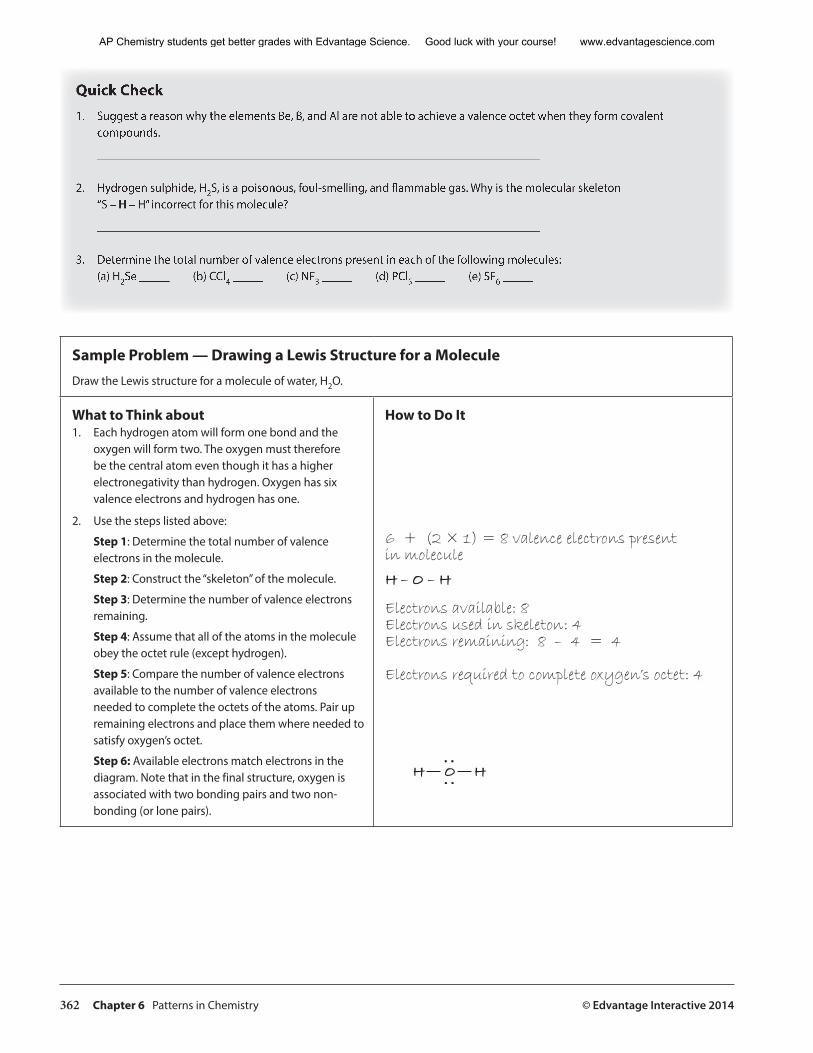
362 Chapter 6 Patterns in Chemistry © Edvantage Interactive 2014
Quick Check1. Suggest a reason why the elements Be, B, and Al are not able to achieve a valence octet when they form covalent
compounds.
_________________________________________________________________________
2. Hydrogen sulphide, H2S, is a poisonous, foul-smelling, and flammable gas. Why is the molecular skeleton “S – H – H” incorrect for this molecule?
_________________________________________________________________________
3. Determine the total number of valence electrons present in each of the following molecules:(a) H2Se _____ (b) CCl4 _____ (c) NF3 _____ (d) PCl5 _____ (e) SF6 _____
Sample Problem — Drawing a Lewis Structure for a MoleculeDraw the Lewis structure for a molecule of water, H2O.
What to Think about1. Each hydrogen atom will form one bond and the
oxygen will form two. The oxygen must therefore be the central atom even though it has a higher electronegativity than hydrogen. Oxygen has six valence electrons and hydrogen has one.
2. Use the steps listed above:
Step 1: Determine the total number of valence electrons in the molecule.
Step 2: Construct the “skeleton” of the molecule.
Step 3: Determine the number of valence electrons remaining.
Step 4: Assume that all of the atoms in the molecule obey the octet rule (except hydrogen).
Step 5: Compare the number of valence electrons available to the number of valence electrons needed to complete the octets of the atoms. Pair up remaining electrons and place them where needed to satisfy oxygen’s octet.
Step 6: Available electrons match electrons in the diagram. Note that in the final structure, oxygen is associated with two bonding pairs and two non-bonding (or lone pairs).
How to Do It
6 + (2 × 1) = 8 valence electrons present in molecule
H – O – H
Electrons available: 8 Electrons used in skeleton: 4 Electrons remaining: 8 – 4 = 4
Electrons required to complete oxygen’s octet: 4
� � �
AP Chemistry students get better grades with Edvantage Science. Good luck with your course! www.edvantagescience.com
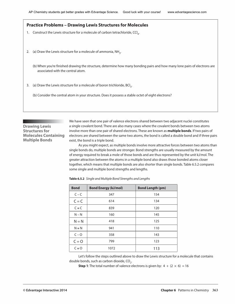
© Edvantage Interactive 2014 Chapter 6 Patterns in Chemistry 363
Practice Problems – Drawing Lewis Structures for Molecules1. Construct the Lewis structure for a molecule of carbon tetrachloride, CCl4.
2. (a) Draw the Lewis structure for a molecule of ammonia, NH3.
(b) When you’re finished drawing the structure, determine how many bonding pairs and how many lone pairs of electrons are associated with the central atom.
3. (a) Draw the Lewis structure for a molecule of boron trichloride, BCl3.
(b) Consider the central atom in your structure. Does it possess a stable octet of eight electrons?
Drawing Lewis Structures for Molecules Containing Multiple Bonds
We have seen that one pair of valence electrons shared between two adjacent nuclei constitutes a single covalent bond. There are also many cases where the covalent bonds between two atoms involve more than one pair of shared electrons. These are known as multiple bonds. If two pairs of electrons are shared between the same two atoms, the bond is called a double bond and if three pairs exist, the bond is a triple bond.
As you might expect, as multiple bonds involve more attractive forces between two atoms than single bonds do, multiple bonds are stronger. Bond strengths are usually measured by the amount of energy required to break a mole of those bonds and are thus represented by the unit kJ/mol. The greater attraction between the atoms in a multiple bond also draws those bonded atoms closer together, which means that multiple bonds are also shorter than single bonds. Table 6.5.2 compares some single and multiple bond strengths and lengths.
Table 6.5.2 Single and Multiple Bond Strengths and Lengths
Bond Bond Energy (kJ/mol) Bond Length (pm)
C – C 347 154
C = C 614 134
C ≡ C 839 120
N – N 160 145
N = N 418 125
N ≡ N 941 110
C – O 358 143
C = O 799 123
C ≡ O 1072 113
Let’s follow the steps outlined above to draw the Lewis structure for a molecule that contains double bonds, such as carbon dioxide, CO2.
Step 1: The total number of valence electrons is given by: 4 + (2 × 6) = 16
AP Chemistry students get better grades with Edvantage Science. Good luck with your course! www.edvantagescience.com
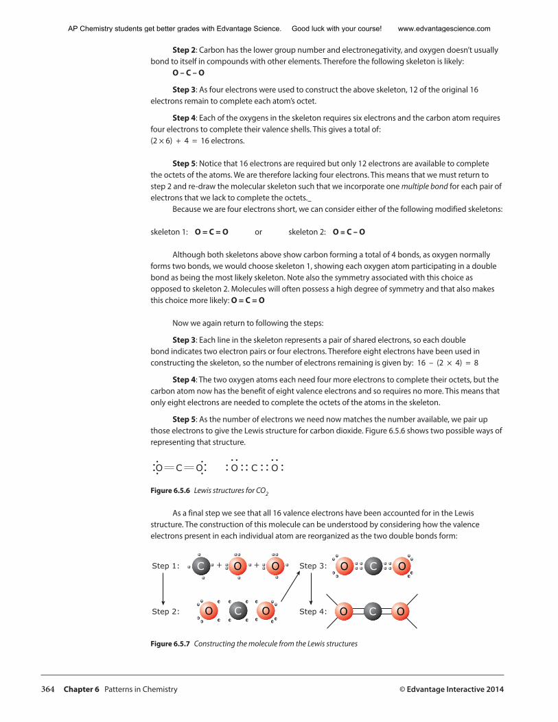
364 Chapter 6 Patterns in Chemistry © Edvantage Interactive 2014
Step 2: Carbon has the lower group number and electronegativity, and oxygen doesn’t usually bond to itself in compounds with other elements. Therefore the following skeleton is likely:
O – C – O
Step 3: As four electrons were used to construct the above skeleton, 12 of the original 16 electrons remain to complete each atom’s octet.
Step 4: Each of the oxygens in the skeleton requires six electrons and the carbon atom requires four electrons to complete their valence shells. This gives a total of: (2 × 6) + 4 = 16 electrons.
Step 5: Notice that 16 electrons are required but only 12 electrons are available to complete the octets of the atoms. We are therefore lacking four electrons. This means that we must return to step 2 and re-draw the molecular skeleton such that we incorporate one multiple bond for each pair of electrons that we lack to complete the octets.
Because we are four electrons short, we can consider either of the following modified skeletons:
skeleton 1: O = C = O or skeleton 2: O ≡ C – O
Although both skeletons above show carbon forming a total of 4 bonds, as oxygen normally forms two bonds, we would choose skeleton 1, showing each oxygen atom participating in a double bond as being the most likely skeleton. Note also the symmetry associated with this choice as opposed to skeleton 2. Molecules will often possess a high degree of symmetry and that also makes this choice more likely: O = C = O
Now we again return to following the steps:
Step 3: Each line in the skeleton represents a pair of shared electrons, so each double bond indicates two electron pairs or four electrons. Therefore eight electrons have been used in constructing the skeleton, so the number of electrons remaining is given by: 16 – (2 × 4) = 8
Step 4: The two oxygen atoms each need four more electrons to complete their octets, but the carbon atom now has the benefit of eight valence electrons and so requires no more. This means that only eight electrons are needed to complete the octets of the atoms in the skeleton.
Step 5: As the number of electrons we need now matches the number available, we pair up those electrons to give the Lewis structure for carbon dioxide. Figure 6.5.6 shows two possible ways of representing that structure.
O OC O OC
Figure 6.5.6 Lewis structures for CO2
As a final step we see that all 16 valence electrons have been accounted for in the Lewis structure. The construction of this molecule can be understood by considering how the valence electrons present in each individual atom are reorganized as the two double bonds form:
O CC O OO
C OO OO
Step 1: Step 3:
Step 2: Step 4: C
� �
Figure 6.5.7 Constructing the molecule from the Lewis structures
AP Chemistry students get better grades with Edvantage Science. Good luck with your course! www.edvantagescience.com
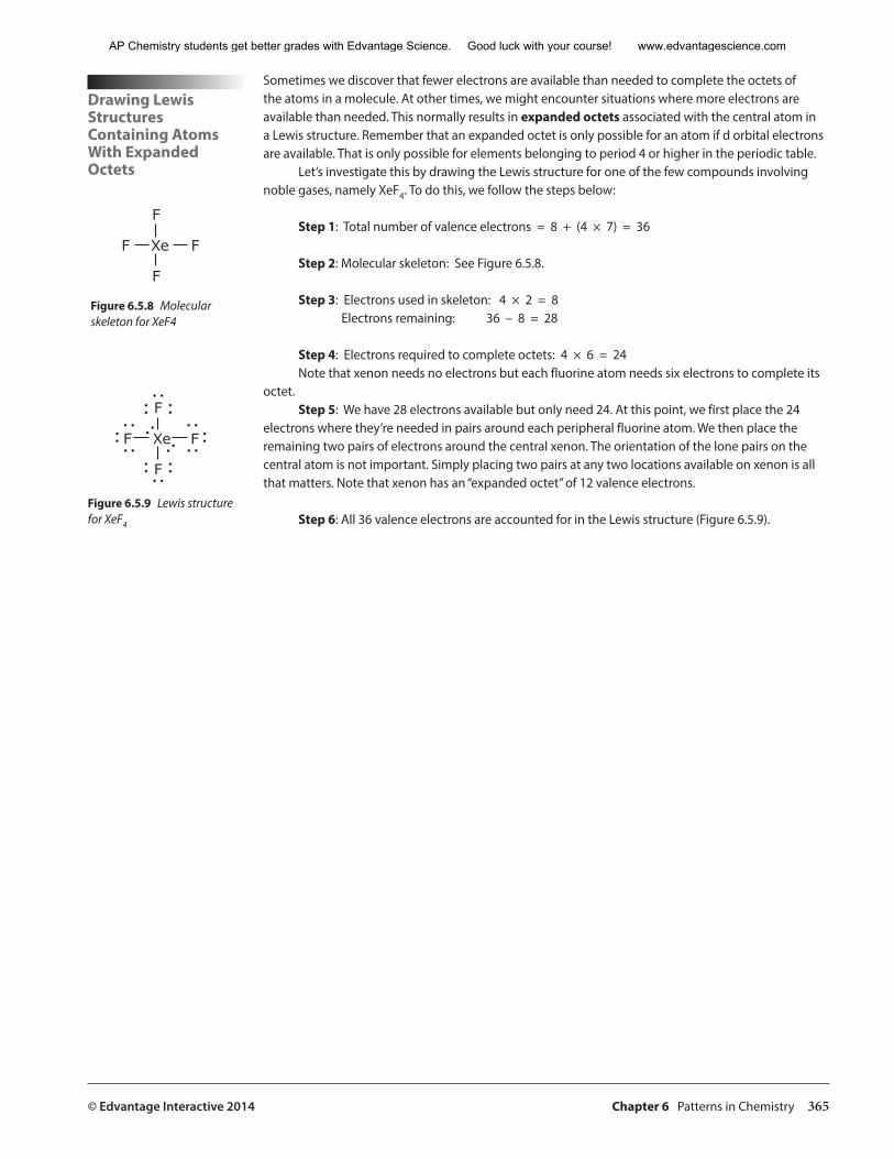
© Edvantage Interactive 2014 Chapter 6 Patterns in Chemistry 365
Drawing Lewis Structures Containing Atoms With Expanded Octets
Sometimes we discover that fewer electrons are available than needed to complete the octets of the atoms in a molecule. At other times, we might encounter situations where more electrons are available than needed. This normally results in expanded octets associated with the central atom in a Lewis structure. Remember that an expanded octet is only possible for an atom if d orbital electrons are available. That is only possible for elements belonging to period 4 or higher in the periodic table.
Let’s investigate this by drawing the Lewis structure for one of the few compounds involving noble gases, namely XeF4. To do this, we follow the steps below:
Step 1: Total number of valence electrons = 8 + (4 × 7) = 36
Step 2: Molecular skeleton: See Figure 6.5.8.
Step 3: Electrons used in skeleton: 4 × 2 = 8 Electrons remaining: 36 – 8 = 28
Step 4: Electrons required to complete octets: 4 × 6 = 24 Note that xenon needs no electrons but each fluorine atom needs six electrons to complete its
octet.Step 5: We have 28 electrons available but only need 24. At this point, we first place the 24
electrons where they’re needed in pairs around each peripheral fluorine atom. We then place the remaining two pairs of electrons around the central xenon. The orientation of the lone pairs on the central atom is not important. Simply placing two pairs at any two locations available on xenon is all that matters. Note that xenon has an “expanded octet” of 12 valence electrons.
Step 6: All 36 valence electrons are accounted for in the Lewis structure (Figure 6.5.9).
F
F
Xe
F
F
Figure 6.5.8 Molecular skeleton for XeF4
F
F
Xe
F
F
Figure 6.5.9 Lewis structure for XeF4
AP Chemistry students get better grades with Edvantage Science. Good luck with your course! www.edvantagescience.com
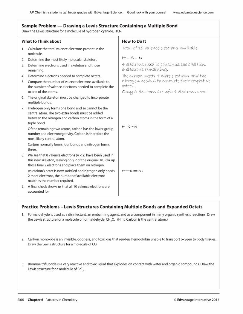
366 Chapter 6 Patterns in Chemistry © Edvantage Interactive 2014
Sample Problem — Drawing a Lewis Structure Containing a Multiple Bond Draw the Lewis structure for a molecule of hydrogen cyanide, HCN.
What to Think about
1. Calculate the total valence electrons present in the molecule.
2. Determine the most likely molecular skeleton.
3. Determine electrons used in skeleton and those remaining.
4. Determine electrons needed to complete octets.
5. Compare the number of valence electrons available to the number of valence electrons needed to complete the octets of the atoms.
6. The original skeleton must be changed to incorporate multiple bonds.
7. Hydrogen only forms one bond and so cannot be the central atom. The two extra bonds must be added between the nitrogen and carbon atoms in the form of a triple bond.
Of the remaining two atoms, carbon has the lower group number and electronegativity. Carbon is therefore the most likely central atom.
Carbon normally forms four bonds and nitrogen forms three.
8. We see that 8 valence electrons (4 × 2) have been used in this new skeleton, leaving only 2 of the original 10. Pair up those final 2 electrons and place them on nitrogen.
As carbon’s octet is now satisfied and nitrogen only needs 2 more electrons, the number of available electrons matches the number required.
9. A final check shows us that all 10 valence electrons are accounted for.
How to Do ItTotal of 10 valence electrons available
H – C – N 4 electrons used to construct the skeleton, 6 electrons remaining. The carbon needs 4 more electrons and the nitrogen needs 6 to complete their respective octets.Only 6 electrons are left: 4 electrons short
H – C ≡ N
� � �
Practice Problems – Lewis Structures Containing Multiple Bonds and Expanded Octets1. Formaldehyde is used as a disinfectant, an embalming agent, and as a component in many organic synthesis reactions. Draw
the Lewis structure for a molecule of formaldehyde, CH2O. (Hint: Carbon is the central atom.)
2. Carbon monoxide is an invisible, odorless, and toxic gas that renders hemoglobin unable to transport oxygen to body tissues. Draw the Lewis structure for a molecule of CO.
3. Bromine trifluoride is a very reactive and toxic liquid that explodes on contact with water and organic compounds. Draw the Lewis structure for a molecule of BrF3.
AP Chemistry students get better grades with Edvantage Science. Good luck with your course! www.edvantagescience.com
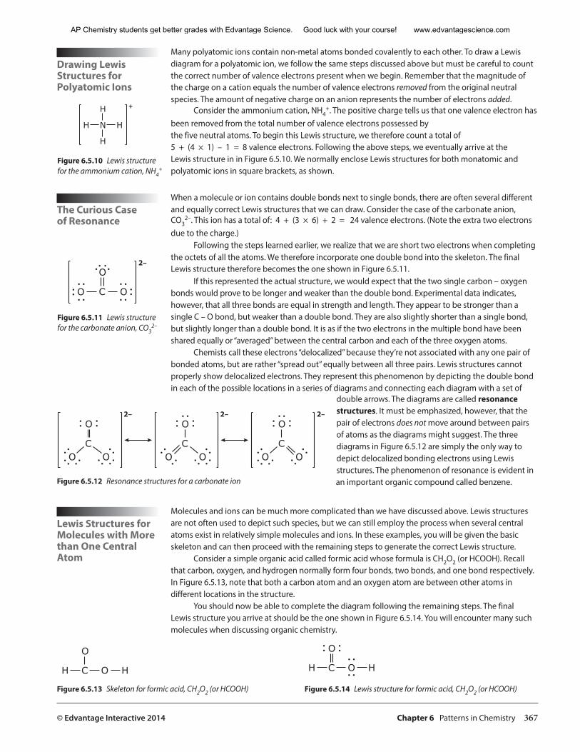
© Edvantage Interactive 2014 Chapter 6 Patterns in Chemistry 367
Drawing Lewis Structures for Polyatomic Ions
The Curious Case of Resonance
Many polyatomic ions contain non-metal atoms bonded covalently to each other. To draw a Lewis diagram for a polyatomic ion, we follow the same steps discussed above but must be careful to count the correct number of valence electrons present when we begin. Remember that the magnitude of the charge on a cation equals the number of valence electrons removed from the original neutral species. The amount of negative charge on an anion represents the number of electrons added.
Consider the ammonium cation, NH4+. The positive charge tells us that one valence electron has
been removed from the total number of valence electrons possessed by the five neutral atoms. To begin this Lewis structure, we therefore count a total of 5 + (4 × 1) – 1 = 8 valence electrons. Following the above steps, we eventually arrive at the Lewis structure in in Figure 6.5.10. We normally enclose Lewis structures for both monatomic and polyatomic ions in square brackets, as shown.
When a molecule or ion contains double bonds next to single bonds, there are often several different and equally correct Lewis structures that we can draw. Consider the case of the carbonate anion, CO3
2–. This ion has a total of: 4 + (3 × 6) + 2 = 24 valence electrons. (Note the extra two electrons due to the charge.)
Following the steps learned earlier, we realize that we are short two electrons when completing the octets of all the atoms. We therefore incorporate one double bond into the skeleton. The final Lewis structure therefore becomes the one shown in Figure 6.5.11.
If this represented the actual structure, we would expect that the two single carbon – oxygen bonds would prove to be longer and weaker than the double bond. Experimental data indicates, however, that all three bonds are equal in strength and length. They appear to be stronger than a single C – O bond, but weaker than a double bond. They are also slightly shorter than a single bond, but slightly longer than a double bond. It is as if the two electrons in the multiple bond have been shared equally or “averaged” between the central carbon and each of the three oxygen atoms.
Chemists call these electrons “delocalized” because they’re not associated with any one pair of bonded atoms, but are rather “spread out” equally between all three pairs. Lewis structures cannot properly show delocalized electrons. They represent this phenomenon by depicting the double bond in each of the possible locations in a series of diagrams and connecting each diagram with a set of
double arrows. The diagrams are called resonance structures. It must be emphasized, however, that the pair of electrons does not move around between pairs of atoms as the diagrams might suggest. The three diagrams in Figure 6.5.12 are simply the only way to depict delocalized bonding electrons using Lewis structures. The phenomenon of resonance is evident in an important organic compound called benzene.
Lewis Structures for Molecules with More than One Central Atom
Molecules and ions can be much more complicated than we have discussed above. Lewis structures are not often used to depict such species, but we can still employ the process when several central atoms exist in relatively simple molecules and ions. In these examples, you will be given the basic skeleton and can then proceed with the remaining steps to generate the correct Lewis structure.
Consider a simple organic acid called formic acid whose formula is CH2O2 (or HCOOH). Recall that carbon, oxygen, and hydrogen normally form four bonds, two bonds, and one bond respectively. In Figure 6.5.13, note that both a carbon atom and an oxygen atom are between other atoms in different locations in the structure.
You should now be able to complete the diagram following the remaining steps. The final Lewis structure you arrive at should be the one shown in Figure 6.5.14. You will encounter many such molecules when discussing organic chemistry.
H
O
C O H H
O
C O H
Figure 6.5.13 Skeleton for formic acid, CH2O2 (or HCOOH) Figure 6.5.14 Lewis structure for formic acid, CH2O2 (or HCOOH)
H
H
N
H
H
+
Figure 6.5.10 Lewis structure for the ammonium cation, NH4
+
O
C OO
2–
Figure 6.5.11 Lewis structure for the carbonate anion, CO3
2–
O
CO O
��O
CO O
��O
CO O
��
Figure 6.5.12 Resonance structures for a carbonate ion
AP Chemistry students get better grades with Edvantage Science. Good luck with your course! www.edvantagescience.com
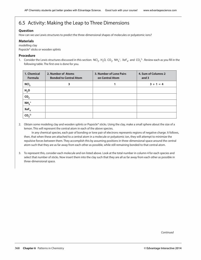
368 Chapter 6 Patterns in Chemistry © Edvantage Interactive 2014
6.5 Activity: Making the Leap to Three Dimensions QuestionHow can we use Lewis structures to predict the three-dimensional shapes of molecules or polyatomic ions?
Materialsmodelling clayPopsicle® sticks or wooden splints
Procedure1. Consider the Lewis structures discussed in this section: NCl3, H2O, CO2, NH4
+, XeF4, and CO32–. Review each as you fill in the
following table. The first one is done for you.
1. ChemicalFormula
2. Number of Atoms Bonded to Central Atom
3. Number of Lone Pairson Central Atom
4. Sum of Columns 2 and 3
NCl3 3 1 3 + 1 = 4
H2O
CO2
NH4+
XeF4
CO32–
2. Obtain some modeling clay and wooden splints or Popsicle® sticks. Using the clay, make a small sphere about the size of a lemon. This will represent the central atom in each of the above species. In any chemical species, each pair of bonding or lone pair of electrons represents regions of negative charge. It follows, then, that when these are attached to a central atom in a molecule or polyatomic ion, they will attempt to minimize the repulsive forces between them. They accomplish this by assuming positions in three-dimensional space around the central atom such that they are as far away from each other as possible, while still remaining bonded to that central atom.
3. To represent this, consider each molecule and ion listed above. Look at the total number in column 4 for each species and select that number of sticks. Now insert them into the clay such that they are all as far away from each other as possible in three-dimensional space.
Continued
AP Chemistry students get better grades with Edvantage Science. Good luck with your course! www.edvantagescience.com
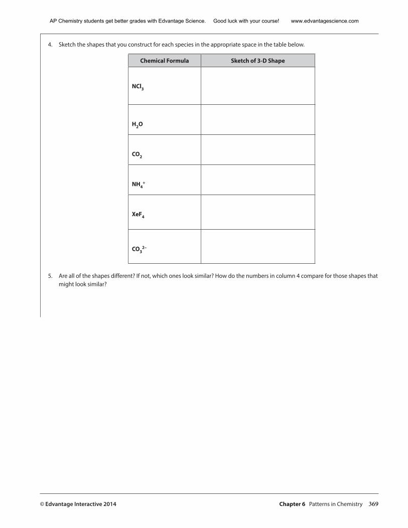
© Edvantage Interactive 2014 Chapter 6 Patterns in Chemistry 369
4. Sketch the shapes that you construct for each species in the appropriate space in the table below.
Chemical Formula Sketch of 3-D Shape
NCl3
H2O
CO2
NH4+
XeF4
CO32–
5. Are all of the shapes different? If not, which ones look similar? How do the numbers in column 4 compare for those shapes that might look similar?
AP Chemistry students get better grades with Edvantage Science. Good luck with your course! www.edvantagescience.com
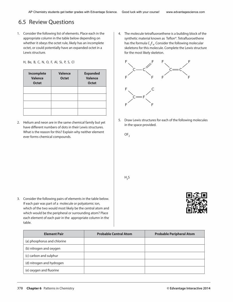
370 Chapter 6 Patterns in Chemistry © Edvantage Interactive 2014
6.5 Review Questions
1. Consider the following list of elements. Place each in the appropriate column in the table below depending on whether it obeys the octet rule, likely has an incomplete octet, or could potentially have an expanded octet in a Lewis structure.
H, Be, B, C, N, O, F, Al, Si, P, S, Cl
IncompleteValence
Octet
ValenceOctet
Expanded Valence
Octet
2. Helium and neon are in the same chemical family but yet have different numbers of dots in their Lewis structures. What is the reason for this? Explain why neither element ever forms chemical compounds.
3. Consider the following pairs of elements in the table below. If each pair was part of a molecule or polyatomic ion, which of the two would most likely be the central atom and which would be the peripheral or surrounding atom? Place each element of each pair in the appropriate column in the table.
Element Pair Probable Central Atom Probable Peripheral Atom
(a) phosphorus and chlorine
(b) nitrogen and oxygen
(c) carbon and sulphur
(d) nitrogen and hydrogen
(e) oxygen and fluorine
4. The molecule tetrafluoroethene is a building block of the synthetic material known as Teflon®. Tetrafluoroethene has the formula C2F4. Consider the following molecular skeletons for this molecule. Complete the Lewis structure for the most likely skeleton.
F
CC
F
F F
F
CC
F
F F
C
FC
F
F F
5. Draw Lewis structures for each of the following molecules in the space provided.
OF2
H2S
AP Chemistry students get better grades with Edvantage Science. Good luck with your course! www.edvantagescience.com
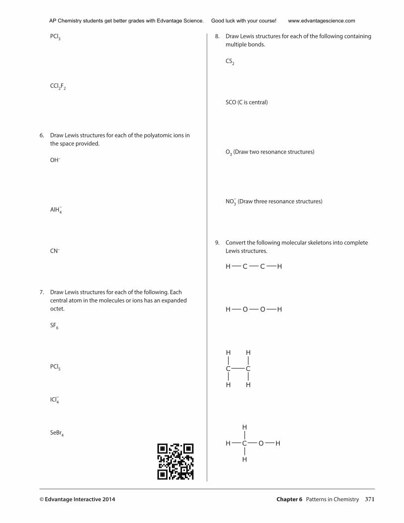
© Edvantage Interactive 2014 Chapter 6 Patterns in Chemistry 371
PCl3
CCl2F2
6. Draw Lewis structures for each of the polyatomic ions in the space provided.
OH–
AlH4–
CN–
7. Draw Lewis structures for each of the following. Each central atom in the molecules or ions has an expanded octet.
SF6
PCl5
ICl4–
SeBr4
8. Draw Lewis structures for each of the following containing multiple bonds.
CS2
SCO (C is central)
O3 (Draw two resonance structures)
NO3– (Draw three resonance structures)
9. Convert the following molecular skeletons into complete Lewis structures.
H C C H
H O O H
H
C
H
H
C
H
H
H
C O H
H
AP Chemistry students get better grades with Edvantage Science. Good luck with your course! www.edvantagescience.com
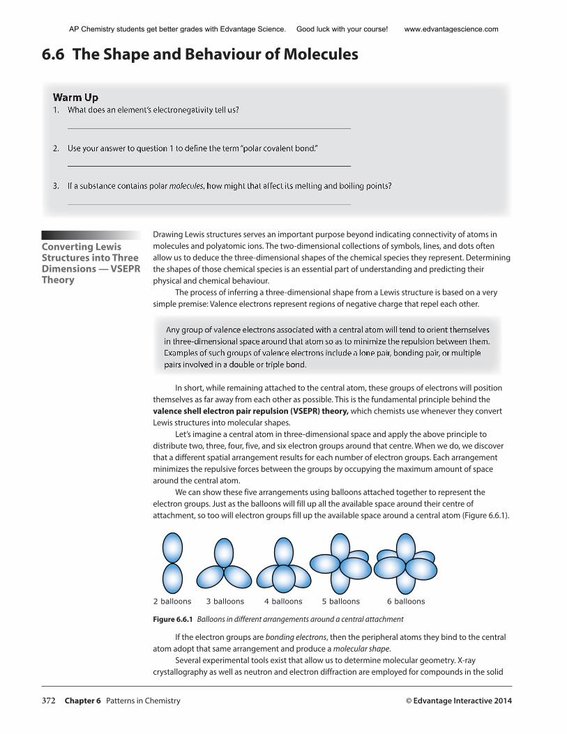
372 Chapter 6 Patterns in Chemistry © Edvantage Interactive 2014
6.6 The Shape and Behaviour of Molecules
Warm Up1. What does an element’s electronegativity tell us?
___________________________________________________________________
2. Use your answer to question 1 to define the term “polar covalent bond.”
___________________________________________________________________
3. If a substance contains polar molecules, how might that affect its melting and boiling points?
___________________________________________________________________
Converting Lewis Structures into Three Dimensions — VSEPR Theory
Drawing Lewis structures serves an important purpose beyond indicating connectivity of atoms in molecules and polyatomic ions. The two-dimensional collections of symbols, lines, and dots often allow us to deduce the three-dimensional shapes of the chemical species they represent. Determining the shapes of those chemical species is an essential part of understanding and predicting their physical and chemical behaviour.
The process of inferring a three-dimensional shape from a Lewis structure is based on a very simple premise: Valence electrons represent regions of negative charge that repel each other.
Any group of valence electrons associated with a central atom will tend to orient themselves in three-dimensional space around that atom so as to minimize the repulsion between them. Examples of such groups of valence electrons include a lone pair, bonding pair, or multiple pairs involved in a double or triple bond.
In short, while remaining attached to the central atom, these groups of electrons will position themselves as far away from each other as possible. This is the fundamental principle behind the valence shell electron pair repulsion (VSEPR) theory, which chemists use whenever they convert Lewis structures into molecular shapes.
Let’s imagine a central atom in three-dimensional space and apply the above principle to distribute two, three, four, five, and six electron groups around that centre. When we do, we discover that a different spatial arrangement results for each number of electron groups. Each arrangement minimizes the repulsive forces between the groups by occupying the maximum amount of space around the central atom.
We can show these five arrangements using balloons attached together to represent the electron groups. Just as the balloons will fill up all the available space around their centre of attachment, so too will electron groups fill up the available space around a central atom (Figure 6.6.1).
2 balloons 3 balloons 4 balloons 5 balloons 6 balloons
Figure 6.6.1 Balloons in different arrangements around a central attachment
If the electron groups are bonding electrons, then the peripheral atoms they bind to the central atom adopt that same arrangement and produce a molecular shape.
Several experimental tools exist that allow us to determine molecular geometry. X-ray crystallography as well as neutron and electron diffraction are employed for compounds in the solid
AP Chemistry students get better grades with Edvantage Science. Good luck with your course! www.edvantagescience.com
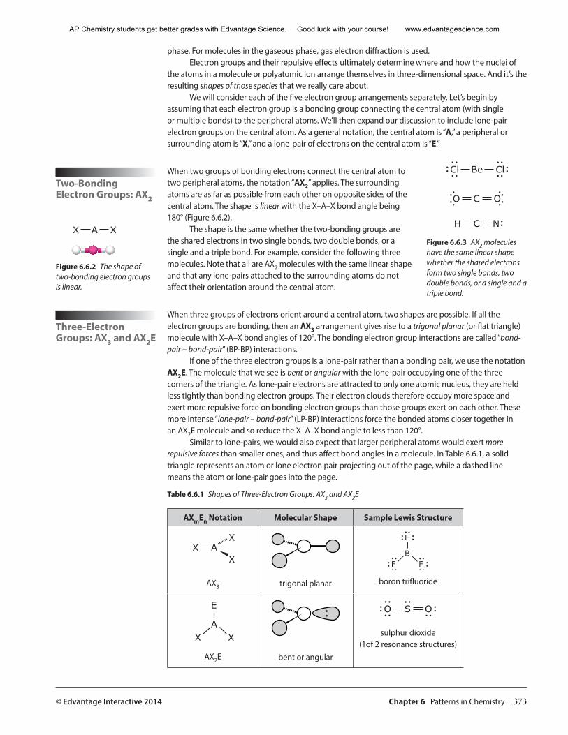
© Edvantage Interactive 2014 Chapter 6 Patterns in Chemistry 373
phase. For molecules in the gaseous phase, gas electron diffraction is used.Electron groups and their repulsive effects ultimately determine where and how the nuclei of
the atoms in a molecule or polyatomic ion arrange themselves in three-dimensional space. And it’s the resulting shapes of those species that we really care about.
We will consider each of the five electron group arrangements separately. Let’s begin by assuming that each electron group is a bonding group connecting the central atom (with single or multiple bonds) to the peripheral atoms. We’ll then expand our discussion to include lone-pair electron groups on the central atom. As a general notation, the central atom is “A,” a peripheral or surrounding atom is “X,” and a lone-pair of electrons on the central atom is “E.”
Two-Bonding Electron Groups: AX2
When two groups of bonding electrons connect the central atom to two peripheral atoms, the notation “AX2” applies. The surrounding atoms are as far as possible from each other on opposite sides of the central atom. The shape is linear with the X–A–X bond angle being 180° (Figure 6.6.2).
The shape is the same whether the two-bonding groups are the shared electrons in two single bonds, two double bonds, or a single and a triple bond. For example, consider the following three molecules. Note that all are AX2 molecules with the same linear shape and that any lone-pairs attached to the surrounding atoms do not affect their orientation around the central atom.
Three-Electron Groups: AX3 and AX2E
When three groups of electrons orient around a central atom, two shapes are possible. If all the electron groups are bonding, then an AX3 arrangement gives rise to a trigonal planar (or flat triangle) molecule with X–A–X bond angles of 120°. The bonding electron group interactions are called “bond-pair – bond-pair” (BP-BP) interactions.
If one of the three electron groups is a lone-pair rather than a bonding pair, we use the notation AX2E. The molecule that we see is bent or angular with the lone-pair occupying one of the three corners of the triangle. As lone-pair electrons are attracted to only one atomic nucleus, they are held less tightly than bonding electron groups. Their electron clouds therefore occupy more space and exert more repulsive force on bonding electron groups than those groups exert on each other. These more intense “lone-pair – bond-pair” (LP-BP) interactions force the bonded atoms closer together in an AX2E molecule and so reduce the X–A–X bond angle to less than 120°.
Similar to lone-pairs, we would also expect that larger peripheral atoms would exert more repulsive forces than smaller ones, and thus affect bond angles in a molecule. In Table 6.6.1, a solid triangle represents an atom or lone electron pair projecting out of the page, while a dashed line means the atom or lone-pair goes into the page.
Table 6.6.1 Shapes of Three-Electron Groups: AX3 and AX2E
AXmEn Notation Molecular Shape Sample Lewis Structure
X AX
X
AX3 trigonal planar
F
BF F
boron trifluoride
E
AX X
AX2E bent or angular
O OS
sulphur dioxide(1of 2 resonance structures)
Be Cl
O OC
H C N
Cl
Figure 6.6.3 AX2 molecules have the same linear shape whether the shared electrons form two single bonds, two double bonds, or a single and a triple bond.
X A X
X A X
Figure 6.6.2 The shape of two-bonding electron groups is linear.
AP Chemistry students get better grades with Edvantage Science. Good luck with your course! www.edvantagescience.com
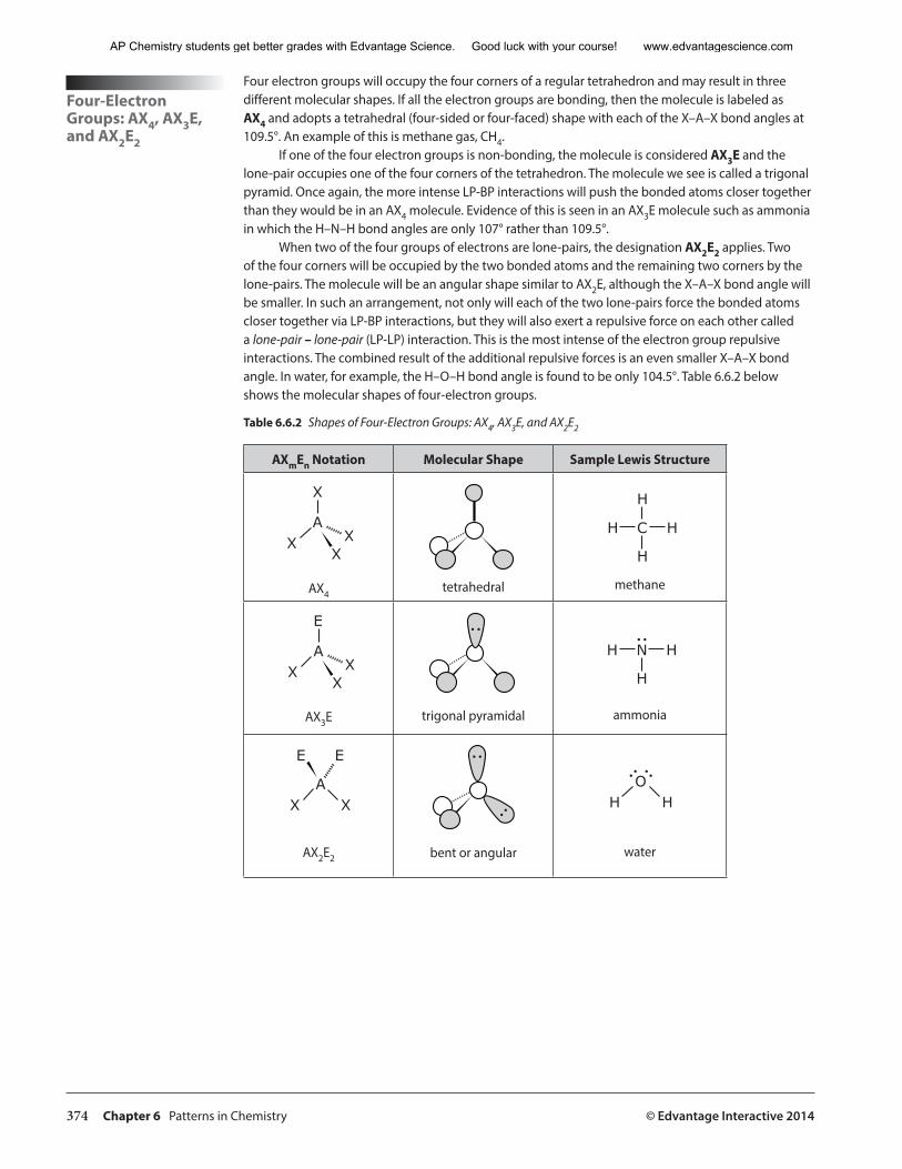
374 Chapter 6 Patterns in Chemistry © Edvantage Interactive 2014
Four-Electron Groups: AX4, AX3E, and AX2E2
Four electron groups will occupy the four corners of a regular tetrahedron and may result in three different molecular shapes. If all the electron groups are bonding, then the molecule is labeled as AX4 and adopts a tetrahedral (four-sided or four-faced) shape with each of the X–A–X bond angles at 109.5°. An example of this is methane gas, CH4.
If one of the four electron groups is non-bonding, the molecule is considered AX3E and the lone-pair occupies one of the four corners of the tetrahedron. The molecule we see is called a trigonal pyramid. Once again, the more intense LP-BP interactions will push the bonded atoms closer together than they would be in an AX4 molecule. Evidence of this is seen in an AX3E molecule such as ammonia in which the H–N–H bond angles are only 107° rather than 109.5°.
When two of the four groups of electrons are lone-pairs, the designation AX2E2 applies. Two of the four corners will be occupied by the two bonded atoms and the remaining two corners by the lone-pairs. The molecule will be an angular shape similar to AX2E, although the X–A–X bond angle will be smaller. In such an arrangement, not only will each of the two lone-pairs force the bonded atoms closer together via LP-BP interactions, but they will also exert a repulsive force on each other called a lone-pair – lone-pair (LP-LP) interaction. This is the most intense of the electron group repulsive interactions. The combined result of the additional repulsive forces is an even smaller X–A–X bond angle. In water, for example, the H–O–H bond angle is found to be only 104.5°. Table 6.6.2 below shows the molecular shapes of four-electron groups.
Table 6.6.2 Shapes of Four-Electron Groups: AX4, AX3E, and AX2E2
AXmEn Notation Molecular Shape Sample Lewis Structure
X
AX X
X
AX4tetrahedral
H
H
C
H
H
methane
E
AX X
X
AX3E trigonal pyramidal
H N
H
H
ammonia
E
AX
E
X
AX2E2 bent or angular
OH H
water
AP Chemistry students get better grades with Edvantage Science. Good luck with your course! www.edvantagescience.com
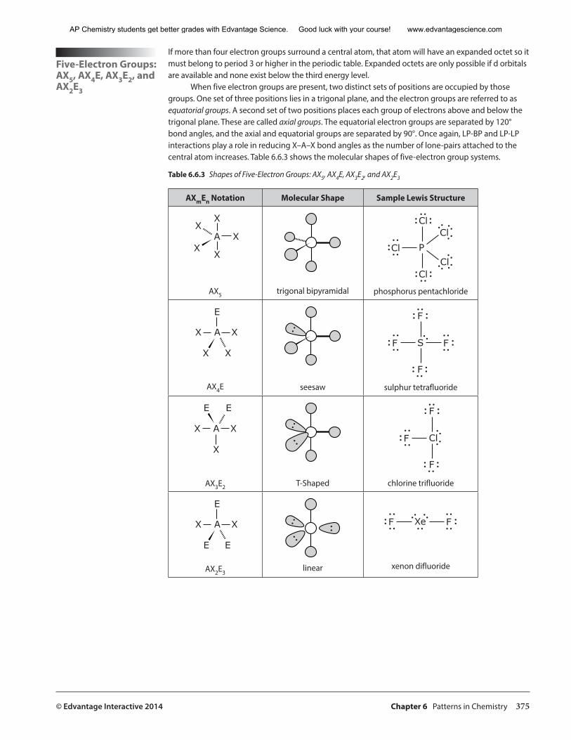
© Edvantage Interactive 2014 Chapter 6 Patterns in Chemistry 375
Five-Electron Groups: AX5, AX4E, AX3E2, and AX2E3
If more than four electron groups surround a central atom, that atom will have an expanded octet so it must belong to period 3 or higher in the periodic table. Expanded octets are only possible if d orbitals are available and none exist below the third energy level.
When five electron groups are present, two distinct sets of positions are occupied by those groups. One set of three positions lies in a trigonal plane, and the electron groups are referred to as equatorial groups. A second set of two positions places each group of electrons above and below the trigonal plane. These are called axial groups. The equatorial electron groups are separated by 120° bond angles, and the axial and equatorial groups are separated by 90°. Once again, LP-BP and LP-LP interactions play a role in reducing X–A–X bond angles as the number of lone-pairs attached to the central atom increases. Table 6.6.3 shows the molecular shapes of five-electron group systems.
Table 6.6.3 Shapes of Five-Electron Groups: AX5, AX4E, AX3E2, and AX2E3
AXmEn Notation Molecular Shape Sample Lewis Structure
X
A
X
XX
X
AX5 trigonal bipyramidal
Cl
P
Cl
Cl
Cl
Cl
phosphorus pentachloride
X A X
E
X X
AX4E seesaw
F
S
F
F F
sulphur tetrafluoride
X A X
X
EE
AX3E2 T-Shaped
F
Cl
F
F
chlorine trifluoride
X A X
E
E E
AX2E3linear
XeF F
xenon difluoride
AP Chemistry students get better grades with Edvantage Science. Good luck with your course! www.edvantagescience.com
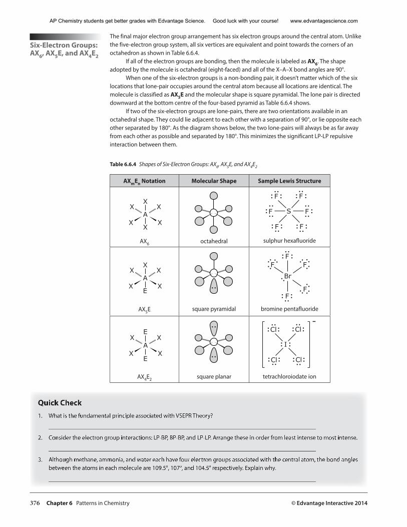
376 Chapter 6 Patterns in Chemistry © Edvantage Interactive 2014
Six-Electron Groups: AX6, AX5E, and AX4E2
The final major electron group arrangement has six electron groups around the central atom. Unlike the five-electron group system, all six vertices are equivalent and point towards the corners of an octahedron as shown in Table 6.6.4.
If all of the electron groups are bonding, then the molecule is labeled as AX6. The shape adopted by the molecule is octahedral (eight-faced) and all of the X–A–X bond angles are 90°.
When one of the six-electron groups is a non-bonding pair, it doesn’t matter which of the six locations that lone-pair occupies around the central atom because all locations are identical. The molecule is classified as AX5E and the molecular shape is square pyramidal. The lone pair is directed downward at the bottom centre of the four-based pyramid as Table 6.6.4 shows.
If two of the six-electron groups are lone-pairs, there are two orientations available in an octahedral shape. They could lie adjacent to each other with a separation of 90°, or lie opposite each other separated by 180°. As the diagram shows below, the two lone-pairs will always be as far away from each other as possible and separated by 180°. This minimizes the significant LP-LP repulsive interaction between them.
Table 6.6.4 Shapes of Six-Electron Groups: AX6, AX5E, and AX4E2
AXmEn Notation Molecular Shape Sample Lewis Structure
X
A
X
X
X
X
X
AX6 octahedral
F
SF F
F
FF
sulphur hexafluoride
X
A
E
X
X
X
X
AX5E square pyramidal
F
Br
F
F
F
F
bromine pentafluoride
E
A
E
X
X
X
X
AX4E2 square planar
Cl
I
Cl
ClCl
-
tetrachloroiodate ion
Quick Check1. What is the fundamental principle associated with VSEPR Theory?
________________________________________________________________________________________
2. Consider the electron group interactions: LP-BP, BP-BP, and LP-LP. Arrange these in order from least intense to most intense.
________________________________________________________________________________________
3. Although methane, ammonia, and water each have four electron groups associated with the central atom, the bond angles between the atoms in each molecule are 109.5°, 107°, and 104.5° respectively. Explain why.
________________________________________________________________________________________
AP Chemistry students get better grades with Edvantage Science. Good luck with your course! www.edvantagescience.com
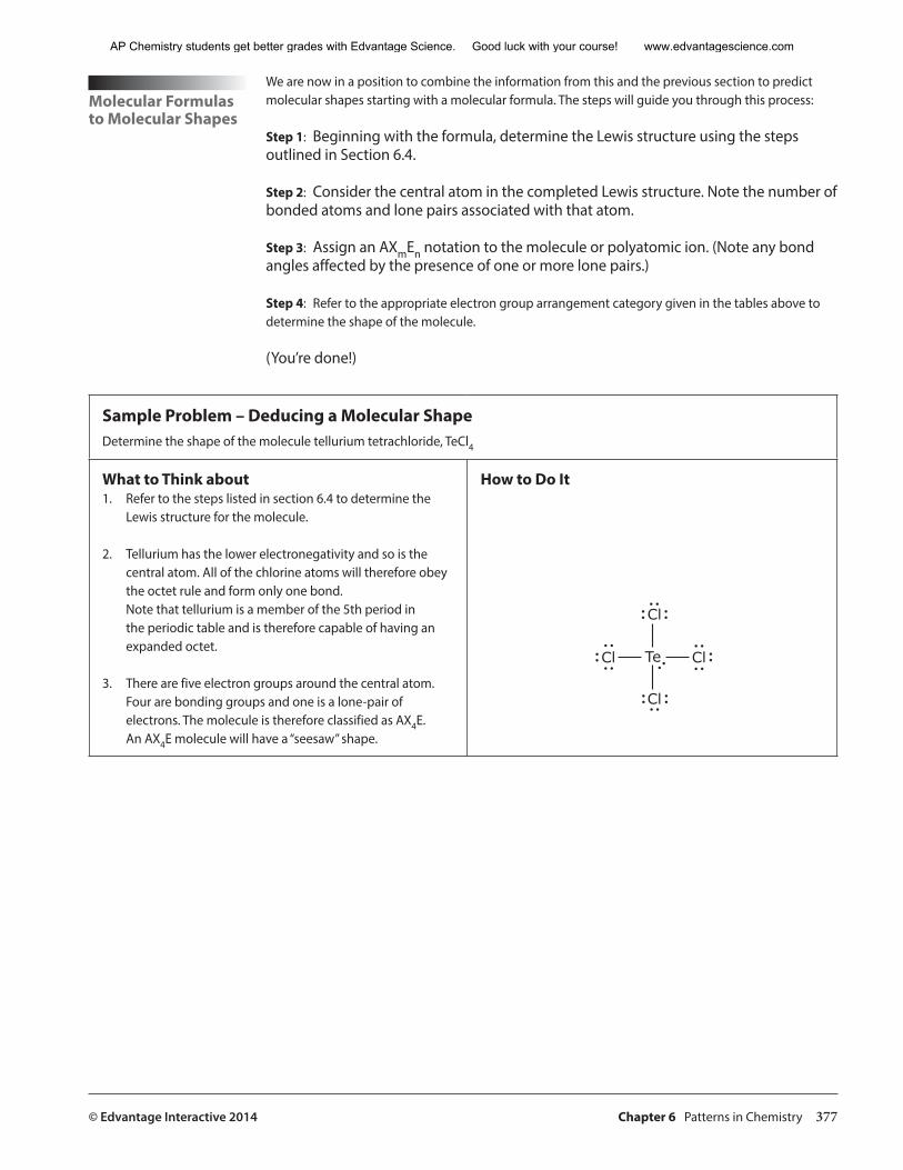
© Edvantage Interactive 2014 Chapter 6 Patterns in Chemistry 377
Molecular Formulas to Molecular Shapes
We are now in a position to combine the information from this and the previous section to predict molecular shapes starting with a molecular formula. The steps will guide you through this process:
Step 1: Beginning with the formula, determine the Lewis structure using the steps outlined in Section 6.4.
Step 2: Consider the central atom in the completed Lewis structure. Note the number of bonded atoms and lone pairs associated with that atom.
Step 3: Assign an AXmEn notation to the molecule or polyatomic ion. (Note any bond angles affected by the presence of one or more lone pairs.)
Step 4: Refer to the appropriate electron group arrangement category given in the tables above to determine the shape of the molecule.
(You’re done!)
Sample Problem – Deducing a Molecular ShapeDetermine the shape of the molecule tellurium tetrachloride, TeCl4
What to Think about1. Refer to the steps listed in section 6.4 to determine the
Lewis structure for the molecule.
2. Tellurium has the lower electronegativity and so is the central atom. All of the chlorine atoms will therefore obey the octet rule and form only one bond.Note that tellurium is a member of the 5th period in the periodic table and is therefore capable of having an expanded octet.
3. There are five electron groups around the central atom. Four are bonding groups and one is a lone-pair of electrons. The molecule is therefore classified as AX4E. An AX4E molecule will have a “seesaw” shape.
How to Do It
Cl
Te
Cl
Cl Cl
AP Chemistry students get better grades with Edvantage Science. Good luck with your course! www.edvantagescience.com
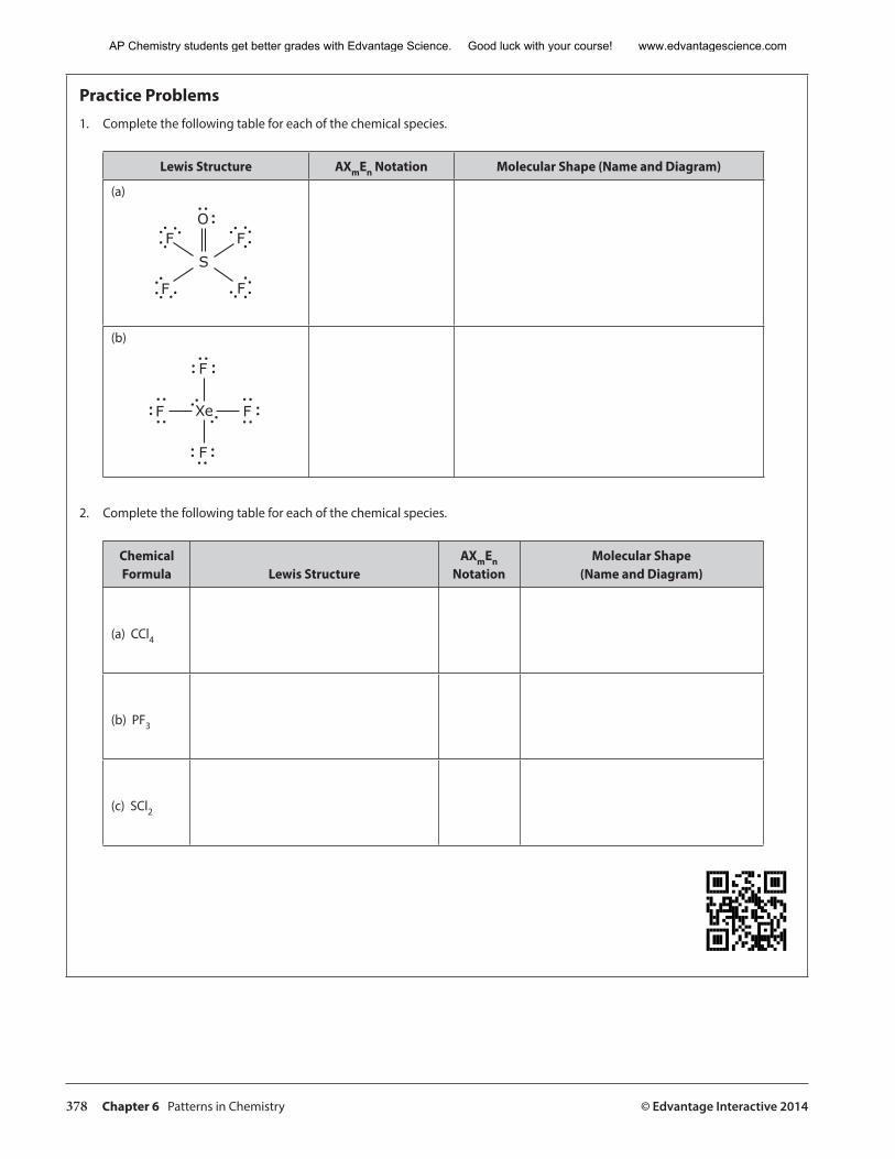
378 Chapter 6 Patterns in Chemistry © Edvantage Interactive 2014
Practice Problems1. Complete the following table for each of the chemical species.
Lewis Structure AXmEn Notation Molecular Shape (Name and Diagram)
(a)
FS
F
F
O
F
(b)
F
Xe
F
F F
2. Complete the following table for each of the chemical species.
Chemical Formula Lewis Structure
AXmEn Notation
Molecular Shape(Name and Diagram)
(a) CCl4
(b) PF3
(c) SCl2
AP Chemistry students get better grades with Edvantage Science. Good luck with your course! www.edvantagescience.com
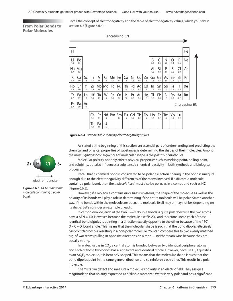
© Edvantage Interactive 2014 Chapter 6 Patterns in Chemistry 379
From Polar Bonds to Polar Molecules
Recall the concept of electronegativity and the table of electronegativity values, which you saw in section 6.2 (Figure 6.6.4).
����
�����
�����
����
�����
�����
�����
�����
�����
�����
�����
�����
�����
�����
����
�����
�����
�����
����
�����
�����
�����
�����
����
�����
��
�����
�����
�����
�����
�����
�����
�����
�����
�����
�����
�����
�����
�����
�����
�����
�����
�����
�����
�����
�����
�����
�����
�����
�����
����
�� �����
�����
�����
�����
�����
�����
�����
�����
�����
����
����
����
����
����
��
�����
�����
����
����
�����
��
�����
�����
�����
�����
�����
��
�����
�����
�����
�����
����
��
�����
�����
�����
�����
�����
��
��
Increasing EN
Increasing EN
Figure 6.6.4 Periodic table showing electronegativity values
As stated at the beginning of this section, an essential part of understanding and predicting the chemical and physical properties of substances is determining the shapes of their molecules. Among the most significant consequences of molecular shape is the polarity of molecules.
Molecular polarity not only affects physical properties such as melting point, boiling point, and solubility, but also influences a substance’s chemical reactivity in both synthetic and biological processes.
Recall that a chemical bond is considered to be polar if electron-sharing in the bond is unequal enough due to the electronegativity differences of the atoms involved. If a diatomic molecule contains a polar bond, then the molecule itself must also be polar, as in a compound such as HCl (Figure 6.6.5).
However, if a molecule contains more than two atoms, the shape of the molecule as well as the polarity of its bonds will play a role in determining if the entire molecule will be polar. Stated another way, if the bonds within the molecule are polar, the molecule itself may or may not be, depending on its shape. Let’s consider an example of each.
In carbon dioxide, each of the two C==O double bonds is quite polar because the two atoms have a ∆EN = 1.0. However, because the molecule itself is AX2 and therefore linear, each of those identical bond dipoles is pointing in a direction exactly opposite to the other because of the 180° O – C – O bond angle. This means that the molecular shape is such that the bond dipoles effectively cancel each other out resulting in a non-polar molecule. You can compare this to two evenly matched tug-of-war teams pulling in opposite directions on a rope — neither team wins because they are equally strong.
In water, just as in CO2, a central atom is bonded between two identical peripheral atoms and each of those two bonds has a significant and identical dipole. However, because H2O qualifies as an AX2E2 molecule, it is bent or V-shaped. This means that the molecular shape is such that the bond dipoles point in the same general direction and so reinforce each other. This results in a polar molecule.
Chemists can detect and measure a molecule’s polarity in an electric field. They assign a magnitude to that polarity expressed as a “dipole moment.” Water is very polar and has a significant
Figure 6.6.5 HCl is a diatomic molecule containing a polar bond.
ClH�+ ��
electron density
AP Chemistry students get better grades with Edvantage Science. Good luck with your course! www.edvantagescience.com
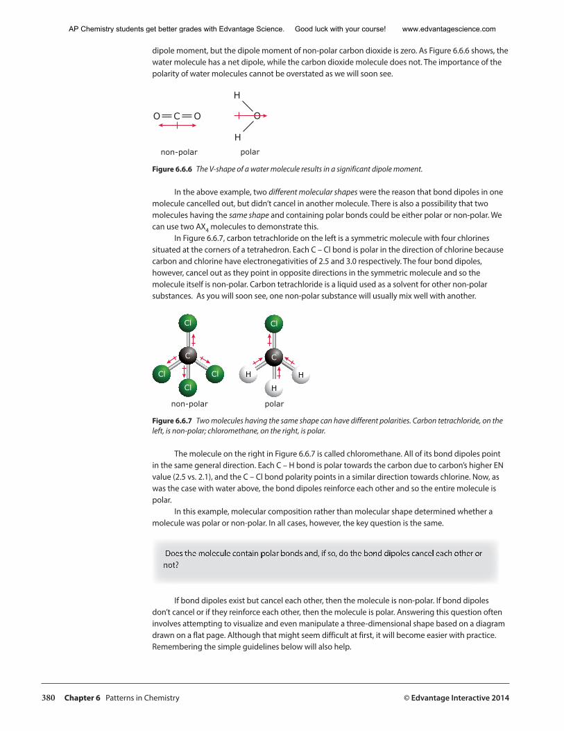
380 Chapter 6 Patterns in Chemistry © Edvantage Interactive 2014
dipole moment, but the dipole moment of non-polar carbon dioxide is zero. As Figure 6.6.6 shows, the water molecule has a net dipole, while the carbon dioxide molecule does not. The importance of the polarity of water molecules cannot be overstated as we will soon see.
O OC O
H
Hnon-polar polar
Figure 6.6.6 The V-shape of a water molecule results in a significant dipole moment.
In the above example, two different molecular shapes were the reason that bond dipoles in one molecule cancelled out, but didn’t cancel in another molecule. There is also a possibility that two molecules having the same shape and containing polar bonds could be either polar or non-polar. We can use two AX4 molecules to demonstrate this.
In Figure 6.6.7, carbon tetrachloride on the left is a symmetric molecule with four chlorines situated at the corners of a tetrahedron. Each C – Cl bond is polar in the direction of chlorine because carbon and chlorine have electronegativities of 2.5 and 3.0 respectively. The four bond dipoles, however, cancel out as they point in opposite directions in the symmetric molecule and so the molecule itself is non-polar. Carbon tetrachloride is a liquid used as a solvent for other non-polar substances. As you will soon see, one non-polar substance will usually mix well with another.
Cl Cl
Cl
Cl
Cl
C C
H
H
H
non-polar polar
Figure 6.6.7 Two molecules having the same shape can have different polarities. Carbon tetrachloride, on the left, is non-polar; chloromethane, on the right, is polar.
The molecule on the right in Figure 6.6.7 is called chloromethane. All of its bond dipoles point in the same general direction. Each C – H bond is polar towards the carbon due to carbon’s higher EN value (2.5 vs. 2.1), and the C – Cl bond polarity points in a similar direction towards chlorine. Now, as was the case with water above, the bond dipoles reinforce each other and so the entire molecule is polar.
In this example, molecular composition rather than molecular shape determined whether a molecule was polar or non-polar. In all cases, however, the key question is the same.
Does the molecule contain polar bonds and, if so, do the bond dipoles cancel each other or not?
If bond dipoles exist but cancel each other, then the molecule is non-polar. If bond dipoles don’t cancel or if they reinforce each other, then the molecule is polar. Answering this question often involves attempting to visualize and even manipulate a three-dimensional shape based on a diagram drawn on a flat page. Although that might seem difficult at first, it will become easier with practice. Remembering the simple guidelines below will also help.
AP Chemistry students get better grades with Edvantage Science. Good luck with your course! www.edvantagescience.com
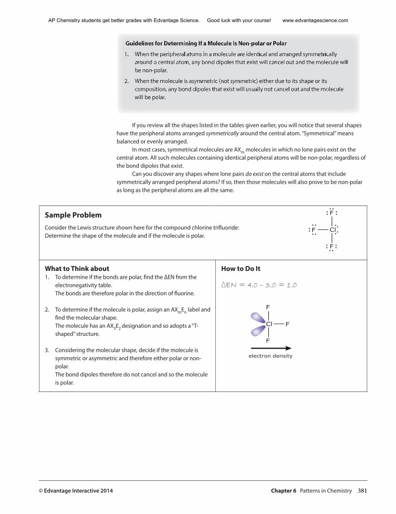
© Edvantage Interactive 2014 Chapter 6 Patterns in Chemistry 381
Guidelines for Determining If a Molecule Is Non-polar or Polar
1. When the peripheral atoms in a molecule are identical and arranged symmetrically around a central atom, any bond dipoles that exist will cancel out and the molecule will be non-polar.
2. When the molecule is asymmetric (not symmetric) either due to its shape or its composition, any bond dipoles that exist will usually not cancel out and the molecule will be polar.
If you review all the shapes listed in the tables given earlier, you will notice that several shapes have the peripheral atoms arranged symmetrically around the central atom. “Symmetrical” means balanced or evenly arranged.
In most cases, symmetrical molecules are AXm molecules in which no lone pairs exist on the central atom. All such molecules containing identical peripheral atoms will be non-polar, regardless of the bond dipoles that exist.
Can you discover any shapes where lone pairs do exist on the central atoms that include symmetrically arranged peripheral atoms? If so, then those molecules will also prove to be non-polar as long as the peripheral atoms are all the same.
Sample ProblemConsider the Lewis structure shown here for the compound chlorine trifluoride: Determine the shape of the molecule and if the molecule is polar.
What to Think about1. To determine if the bonds are polar, find the ∆EN from the
electronegativity table. The bonds are therefore polar in the direction of fluorine.
2. To determine if the molecule is polar, assign an AXmEn label and find the molecular shape. The molecule has an AX3E2 designation and so adopts a “T-shaped” structure.
3. Considering the molecular shape, decide if the molecule is symmetric or asymmetric and therefore either polar or non-polar.The bond dipoles therefore do not cancel and so the molecule is polar.
How to Do It
∆EN = 4.0 – 3.0 = 1.0
F
Cl
F
F
F
Cl
F
F
electron density
AP Chemistry students get better grades with Edvantage Science. Good luck with your course! www.edvantagescience.com
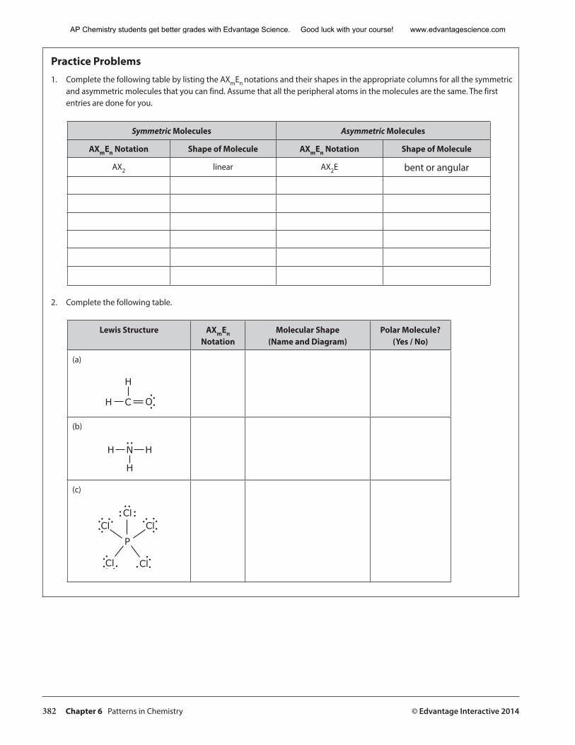
382 Chapter 6 Patterns in Chemistry © Edvantage Interactive 2014
Practice Problems1. Complete the following table by listing the AXmEn notations and their shapes in the appropriate columns for all the symmetric
and asymmetric molecules that you can find. Assume that all the peripheral atoms in the molecules are the same. The first entries are done for you.
Symmetric Molecules Asymmetric Molecules
AXmEn Notation Shape of Molecule AXmEn Notation Shape of Molecule
AX2 linear AX2E bent or angular
2. Complete the following table.
Lewis Structure AXmEn Notation
Molecular Shape (Name and Diagram)
Polar Molecule?(Yes / No)
(a)
OH C
H
(b)
H N
H
H
(c)
Cl
P
Cl
ClCl
Cl
AP Chemistry students get better grades with Edvantage Science. Good luck with your course! www.edvantagescience.com
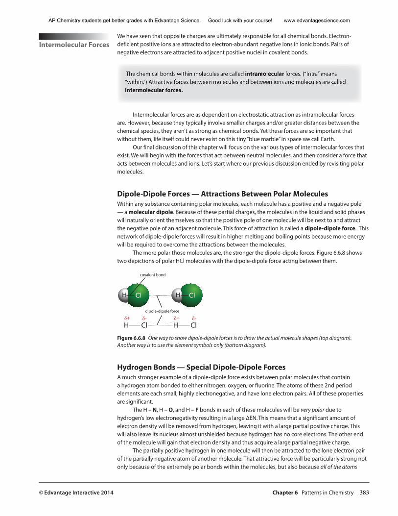
© Edvantage Interactive 2014 Chapter 6 Patterns in Chemistry 383
Intermolecular Forces
We have seen that opposite charges are ultimately responsible for all chemical bonds. Electron-deficient positive ions are attracted to electron-abundant negative ions in ionic bonds. Pairs of negative electrons are attracted to adjacent positive nuclei in covalent bonds.
The chemical bonds within molecules are called intramolecular forces. (“Intra” means “within.”) Attractive forces between molecules and between ions and molecules are called intermolecular forces.
Intermolecular forces are as dependent on electrostatic attraction as intramolecular forces are. However, because they typically involve smaller charges and/or greater distances between the chemical species, they aren’t as strong as chemical bonds. Yet these forces are so important that without them, life itself could never exist on this tiny “blue marble” in space we call Earth.
Our final discussion of this chapter will focus on the various types of intermolecular forces that exist. We will begin with the forces that act between neutral molecules, and then consider a force that acts between molecules and ions. Let’s start where our previous discussion ended by revisiting polar molecules.
Dipole-Dipole Forces — Attractions Between Polar Molecules Within any substance containing polar molecules, each molecule has a positive and a negative pole — a molecular dipole. Because of these partial charges, the molecules in the liquid and solid phases will naturally orient themselves so that the positive pole of one molecule will be next to and attract the negative pole of an adjacent molecule. This force of attraction is called a dipole-dipole force. This network of dipole-dipole forces will result in higher melting and boiling points because more energy will be required to overcome the attractions between the molecules.
The more polar those molecules are, the stronger the dipole-dipole forces. Figure 6.6.8 shows two depictions of polar HCl molecules with the dipole-dipole force acting between them.
ClH ClH
H Cl H Cl�+ �� �+ ��
dipole-dipole force
covalent bond
Figure 6.6.8 One way to show dipole-dipole forces is to draw the actual molecule shapes (top diagram). Another way is to use the element symbols only (bottom diagram).
Hydrogen Bonds — Special Dipole-Dipole Forces A much stronger example of a dipole-dipole force exists between polar molecules that contain a hydrogen atom bonded to either nitrogen, oxygen, or fluorine. The atoms of these 2nd period elements are each small, highly electronegative, and have lone electron pairs. All of these properties are significant.
The H – N, H – O, and H – F bonds in each of these molecules will be very polar due to hydrogen’s low electronegativity resulting in a large ∆EN. This means that a significant amount of electron density will be removed from hydrogen, leaving it with a large partial positive charge. This will also leave its nucleus almost unshielded because hydrogen has no core electrons. The other end of the molecule will gain that electron density and thus acquire a large partial negative charge.
The partially positive hydrogen in one molecule will then be attracted to the lone electron pair of the partially negative atom of another molecule. That attractive force will be particularly strong not only because of the extremely polar bonds within the molecules, but also because all of the atoms
AP Chemistry students get better grades with Edvantage Science. Good luck with your course! www.edvantagescience.com
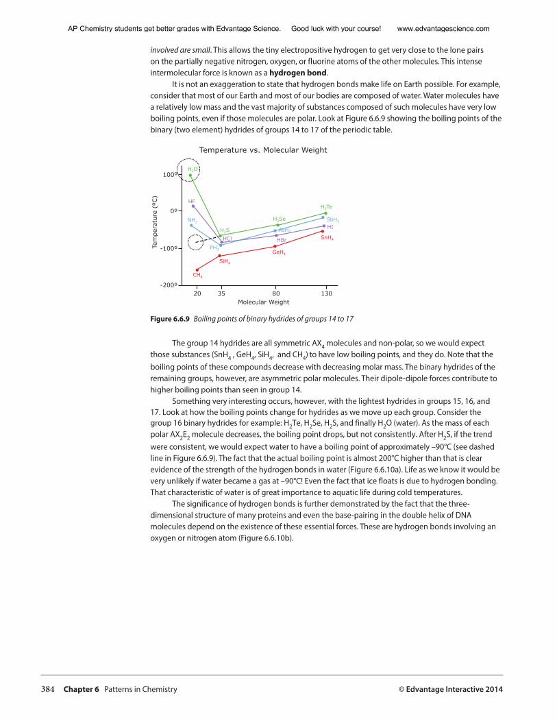
384 Chapter 6 Patterns in Chemistry © Edvantage Interactive 2014
involved are small. This allows the tiny electropositive hydrogen to get very close to the lone pairs on the partially negative nitrogen, oxygen, or fluorine atoms of the other molecules. This intense intermolecular force is known as a hydrogen bond.
It is not an exaggeration to state that hydrogen bonds make life on Earth possible. For example, consider that most of our Earth and most of our bodies are composed of water. Water molecules have a relatively low mass and the vast majority of substances composed of such molecules have very low boiling points, even if those molecules are polar. Look at Figure 6.6.9 showing the boiling points of the binary (two element) hydrides of groups 14 to 17 of the periodic table.
Molecular Weight
)Cº( er
utarep
meT
20 35 80 130-200º
-100º
0º
100ºH2O
H2S
H2Se
H2TeHF
HCl
HI
HBr
NH3
PH3
SbH3
AsH3
CH4
SiH4
GeH4
SnH4
Temperature vs. Molecular Weight
Figure 6.6.9 Boiling points of binary hydrides of groups 14 to 17
The group 14 hydrides are all symmetric AX4 molecules and non-polar, so we would expect those substances (SnH4 , GeH4, SiH4, and CH4) to have low boiling points, and they do. Note that the boiling points of these compounds decrease with decreasing molar mass. The binary hydrides of the remaining groups, however, are asymmetric polar molecules. Their dipole-dipole forces contribute to higher boiling points than seen in group 14.
Something very interesting occurs, however, with the lightest hydrides in groups 15, 16, and 17. Look at how the boiling points change for hydrides as we move up each group. Consider the group 16 binary hydrides for example: H2Te, H2Se, H2S, and finally H2O (water). As the mass of each polar AX2E2 molecule decreases, the boiling point drops, but not consistently. After H2S, if the trend were consistent, we would expect water to have a boiling point of approximately –90°C (see dashed line in Figure 6.6.9). The fact that the actual boiling point is almost 200°C higher than that is clear evidence of the strength of the hydrogen bonds in water (Figure 6.6.10a). Life as we know it would be very unlikely if water became a gas at –90°C! Even the fact that ice floats is due to hydrogen bonding. That characteristic of water is of great importance to aquatic life during cold temperatures.
The significance of hydrogen bonds is further demonstrated by the fact that the three-dimensional structure of many proteins and even the base-pairing in the double helix of DNA molecules depend on the existence of these essential forces. These are hydrogen bonds involving an oxygen or nitrogen atom (Figure 6.6.10b).
AP Chemistry students get better grades with Edvantage Science. Good luck with your course! www.edvantagescience.com
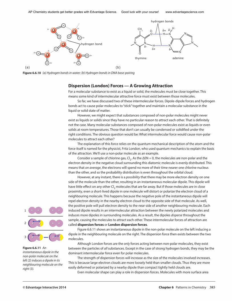
© Edvantage Interactive 2014 Chapter 6 Patterns in Chemistry 385
O
O O
OOH
H
HH
H
H
H H
H
H
hydrogen bond
�
� �
�
�
(a) (b)
NN
NN
NN
N
H
H
H
O
O
�
�
adeninethymine
hydrogen bonds
���
Figure 6.6.10 (a) Hydrogen bonds in water; (b) Hydrogen bonds in DNA base-pairing
Dispersion (London) Forces — A Growing AttractionFor a molecular substance to exist as a liquid or solid, the molecules must be close together. This means some kind of intermolecular attractive force must exist between those molecules.
So far, we have discussed two of these intermolecular forces. Dipole-dipole forces and hydrogen bonds act to cause polar molecules to “stick” together and maintain a molecular substance in the liquid or solid state of matter.
However, we might expect that substances composed of non-polar molecules might never exist as liquids or solids since they have no particular reason to attract each other. That is definitely not the case. Many molecular substances composed of non-polar molecules exist as liquids or even solids at room temperatures. Those that don’t can usually be condensed or solidified under the right conditions. The obvious question would be: What intermolecular force would cause non-polar molecules to attract each other?
The explanation of this force relies on the quantum mechanical description of the atom and the force itself is named for the physicist, Fritz London, who used quantum mechanics to explain the basis of the attraction. We’ll use a non-polar molecule as an example.
Consider a sample of chlorine gas, Cl2. As the ∆EN = 0, the molecules are non-polar and the electron density in the negative cloud surrounding this diatomic molecule is evenly distributed. This means that on average, the electrons will spend no more of their time nearer one chlorine nucleus than the other, and so the probability distribution is even throughout the orbital cloud.
However, at any instant, there is a possibility that there may be more electron density on one side of the molecule than the other, resulting in an instantaneous molecular dipole. This dipole will have little effect on any other Cl2 molecules that are far away. But if those molecules are in close proximity, even a short-lived dipole in one molecule will distort or polarize the electron cloud of a neighbouring molecule. This happens because the negative pole of the instantaneous dipole will repel electron density in the nearby electron cloud to the opposite side of that molecule. As well, the positive pole will pull electron density to the near side of another neighbouring molecule. Each induced dipole results in an intermolecular attraction between the newly polarized molecules and induces more dipoles in surrounding molecules. As a result, the dipoles disperse throughout the sample, causing the molecules to attract each other. These intermolecular forces of attraction are called dispersion forces or London dispersion forces.
Figure 6.6.11 shows an instantaneous dipole in the non-polar molecule on the left inducing a dipole in the neighbouring molecule on the right. The dispersion force then exists between the two molecules.
Although London forces are the only forces acting between non-polar molecules, they exist between the particles of all substances. Except in the case of strong hydrogen bonds, they may be the dominant intermolecular force even for polar molecules.
The strength of dispersion forces will increase as the size of the molecules involved increases. This is because large electron clouds are more loosely held than smaller clouds. Thus they are more easily deformed or polarized by a nearby dipole than compact tightly held clouds are.
Even molecular shape can play a role in dispersion forces. Molecules with more surface area
1
2
3
Figure 6.6.11 An instantaneous dipole in the non-polar molecule on the left (2) induces a dipole in its neighbouring molecule on the right (3).
AP Chemistry students get better grades with Edvantage Science. Good luck with your course! www.edvantagescience.com
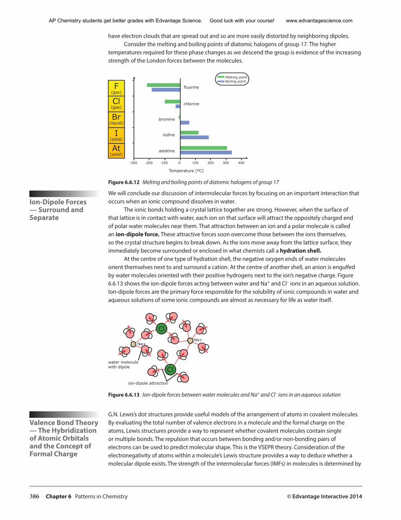
386 Chapter 6 Patterns in Chemistry © Edvantage Interactive 2014
have electron clouds that are spread out and so are more easily distorted by neighboring dipoles. Consider the melting and boiling points of diatomic halogens of group 17. The higher
temperatures required for these phase changes as we descend the group is evidence of the increasing strength of the London forces between the molecules.
F(gas)
Cl(gas)
Br(liquid)
I(solid)
At(solid)
-300 -200 -100 0 100 200 300 400
fluorine
chlorine
bromine
iodine
astatine
Temperature (ºC)
Melting pointBoiling point
Figure 6.6.12 Melting and boiling points of diatomic halogens of group 17
Ion-Dipole Forces — Surround and Separate
We will conclude our discussion of intermolecular forces by focusing on an important interaction that occurs when an ionic compound dissolves in water.
The ionic bonds holding a crystal lattice together are strong. However, when the surface of that lattice is in contact with water, each ion on that surface will attract the oppositely charged end of polar water molecules near them. That attraction between an ion and a polar molecule is called an ion-dipole force. These attractive forces soon overcome those between the ions themselves, so the crystal structure begins to break down. As the ions move away from the lattice surface, they immediately become surrounded or enclosed in what chemists call a hydration shell.
At the centre of one type of hydration shell, the negative oxygen ends of water molecules orient themselves next to and surround a cation. At the centre of another shell, an anion is engulfed by water molecules oriented with their positive hydrogens next to the ion’s negative charge. Figure 6.6.13 shows the ion-dipole forces acting between water and Na+ and Cl– ions in an aqueous solution. Ion-dipole forces are the primary force responsible for the solubility of ionic compounds in water and aqueous solutions of some ionic compounds are almost as necessary for life as water itself.
Cl
Cl
Na+Na+
ion-dipole attraction
water moleculewith dipole
Figure 6.6.13 Ion-dipole forces between water molecules and Na+ and Cl– ions in an aqueous solution
Valence Bond Theory — The Hybridization of Atomic Orbitals and the Concept of Formal Charge
G.N. Lewis’s dot structures provide useful models of the arrangement of atoms in covalent molecules. By evaluating the total number of valence electrons in a molecule and the formal charge on the atoms, Lewis structures provide a way to represent whether covalent molecules contain single or multiple bonds. The repulsion that occurs between bonding and/or non-bonding pairs of electrons can be used to predict molecular shape. This is the VSEPR theory. Consideration of the electronegativity of atoms within a molecule’s Lewis structure provides a way to deduce whether a molecular dipole exists. The strength of the intermolecular forces (IMFs) in molecules is determined by
AP Chemistry students get better grades with Edvantage Science. Good luck with your course! www.edvantagescience.com
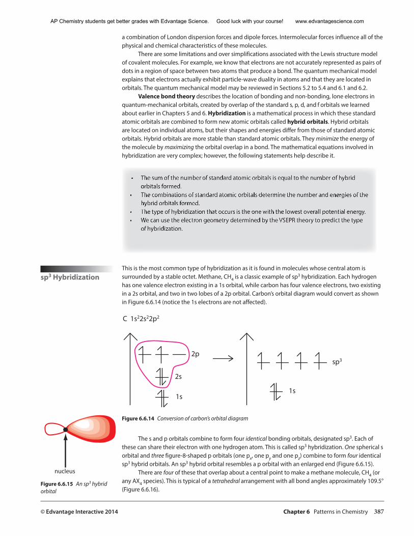
© Edvantage Interactive 2014 Chapter 6 Patterns in Chemistry 387
a combination of London dispersion forces and dipole forces. Intermolecular forces influence all of the physical and chemical characteristics of these molecules.
There are some limitations and over simplifications associated with the Lewis structure model of covalent molecules. For example, we know that electrons are not accurately represented as pairs of dots in a region of space between two atoms that produce a bond. The quantum mechanical model explains that electrons actually exhibit particle-wave duality in atoms and that they are located in orbitals. The quantum mechanical model may be reviewed in Sections 5.2 to 5.4 and 6.1 and 6.2.
Valence bond theory describes the location of bonding and non-bonding, lone electrons in quantum-mechanical orbitals, created by overlap of the standard s, p, d, and f orbitals we learned about earlier in Chapters 5 and 6. Hybridization is a mathematical process in which these standard atomic orbitals are combined to form new atomic orbitals called hybrid orbitals. Hybrid orbitals are located on individual atoms, but their shapes and energies differ from those of standard atomic orbitals. Hybrid orbitals are more stable than standard atomic orbitals. They minimize the energy of the molecule by maximizing the orbital overlap in a bond. The mathematical equations involved in hybridization are very complex; however, the following statements help describe it.
• The sum of the number of standard atomic orbitals is equal to the number of hybrid orbitals formed.
• The combinations of standard atomic orbitals determine the number and energies of the hybrid orbitals formed.
• The type of hybridization that occurs is the one with the lowest overall potential energy. • We can use the electron geometry determined by the VSEPR theory to predict the type
of hybridization.
sp3 HybridizationThis is the most common type of hybridization as it is found in molecules whose central atom is surrounded by a stable octet. Methane, CH4 is a classic example of sp3 hybridization. Each hydrogen has one valence electron existing in a 1s orbital, while carbon has four valence electrons, two existing in a 2s orbital, and two in two lobes of a 2p orbital. Carbon’s orbital diagram would convert as shown in Figure 6.6.14 (notice the 1s electrons are not affected).
������������
��
��
��
���
��
Figure 6.6.14 Conversion of carbon’s orbital diagram
The s and p orbitals combine to form four identical bonding orbitals, designated sp3. Each of these can share their electron with one hydrogen atom. This is called sp3 hybridization. One spherical s orbital and three figure-8-shaped p orbitals (one px, one py and one pz) combine to form four identical sp3 hybrid orbitals. An sp3 hybrid orbital resembles a p orbital with an enlarged end (Figure 6.6.15).
There are four of these that overlap about a central point to make a methane molecule, CH4 (or any AX4 species). This is typical of a tetrahedral arrangement with all bond angles approximately 109.5° (Figure 6.6.16).
�������
Figure 6.6.15 An sp3 hybrid orbital
AP Chemistry students get better grades with Edvantage Science. Good luck with your course! www.edvantagescience.com
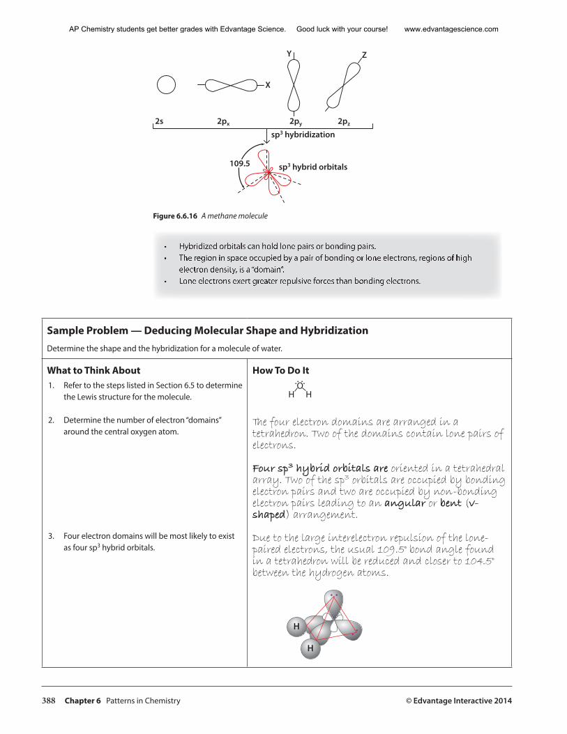
388 Chapter 6 Patterns in Chemistry © Edvantage Interactive 2014
�� ��� ��� ���
�
�
�
�����������������
����� �������������������
Figure 6.6.16 A methane molecule
• Hybridized orbitals can hold lone pairs or bonding pairs.• The region in space occupied by a pair of bonding or lone electrons, regions of high
electron density, is a “domain”.• Lone electrons exert greater repulsive forces than bonding electrons.
Sample Problem — Deducing Molecular Shape and HybridizationDetermine the shape and the hybridization for a molecule of water.
What to Think About1. Refer to the steps listed in Section 6.5 to determine
the Lewis structure for the molecule.
2. Determine the number of electron “domains” around the central oxygen atom.
3. Four electron domains will be most likely to exist as four sp3 hybrid orbitals.
How To Do It
� ��
The four electron domains are arranged in a tetrahedron. Two of the domains contain lone pairs of electrons.
Four sp3 hybrid orbitals are oriented in a tetrahedral array. Two of the sp3 orbitals are occupied by bonding electron pairs and two are occupied by non-bonding electron pairs leading to an angular or bent (v-shaped) arrangement.
Due to the large interelectron repulsion of the lone-paired electrons, the usual 109.5° bond angle found in a tetrahedron will be reduced and closer to 104.5° between the hydrogen atoms.
�
�
AP Chemistry students get better grades with Edvantage Science. Good luck with your course! www.edvantagescience.com
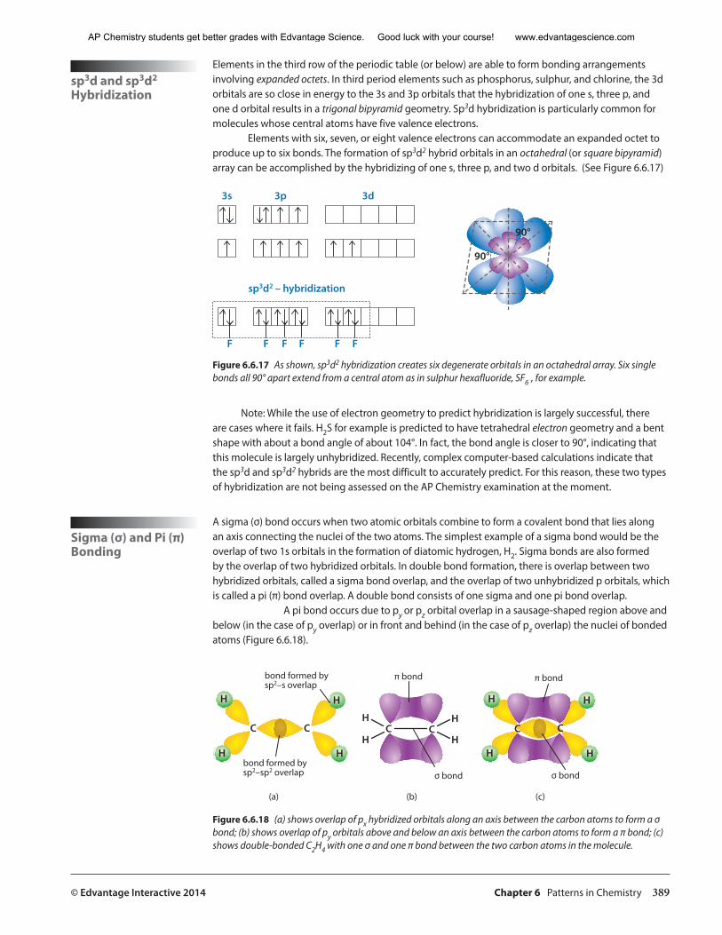
© Edvantage Interactive 2014 Chapter 6 Patterns in Chemistry 389
sp3d and sp3d2 Hybridization
Elements in the third row of the periodic table (or below) are able to form bonding arrangements involving expanded octets. In third period elements such as phosphorus, sulphur, and chlorine, the 3d orbitals are so close in energy to the 3s and 3p orbitals that the hybridization of one s, three p, and one d orbital results in a trigonal bipyramid geometry. Sp3d hybridization is particularly common for molecules whose central atoms have five valence electrons.
Elements with six, seven, or eight valence electrons can accommodate an expanded octet to produce up to six bonds. The formation of sp3d2 hybrid orbitals in an octahedral (or square bipyramid) array can be accomplished by the hybridizing of one s, three p, and two d orbitals. (See Figure 6.6.17)
���
���
�� �� ��
���������������������
� � � � � �
Figure 6.6.17 As shown, sp3d2 hybridization creates six degenerate orbitals in an octahedral array. Six single bonds all 90° apart extend from a central atom as in sulphur hexafluoride, SF6 , for example.
Note: While the use of electron geometry to predict hybridization is largely successful, there are cases where it fails. H2S for example is predicted to have tetrahedral electron geometry and a bent shape with about a bond angle of about 104°. In fact, the bond angle is closer to 90°, indicating that this molecule is largely unhybridized. Recently, complex computer-based calculations indicate that the sp3d and sp3d2 hybrids are the most difficult to accurately predict. For this reason, these two types of hybridization are not being assessed on the AP Chemistry examination at the moment.
Sigma (σ) and Pi (π) Bonding
A sigma (σ) bond occurs when two atomic orbitals combine to form a covalent bond that lies along an axis connecting the nuclei of the two atoms. The simplest example of a sigma bond would be the overlap of two 1s orbitals in the formation of diatomic hydrogen, H2. Sigma bonds are also formed by the overlap of two hybridized orbitals. In double bond formation, there is overlap between two hybridized orbitals, called a sigma bond overlap, and the overlap of two unhybridized p orbitals, which is called a pi (π) bond overlap. A double bond consists of one sigma and one pi bond overlap.
A pi bond occurs due to py or pz orbital overlap in a sausage-shaped region above and below (in the case of py overlap) or in front and behind (in the case of pz overlap) the nuclei of bonded atoms (Figure 6.6.18).
�
� �
�
��
�
� �
�
�� ���
� �
�
������������������������������
����������������������������
������
������ ������
������
��� ��� ���
Figure 6.6.18 (a) shows overlap of px hybridized orbitals along an axis between the carbon atoms to form a σ bond; (b) shows overlap of py orbitals above and below an axis between the carbon atoms to form a π bond; (c) shows double-bonded C2H4 with one σ and one π bond between the two carbon atoms in the molecule.
AP Chemistry students get better grades with Edvantage Science. Good luck with your course! www.edvantagescience.com
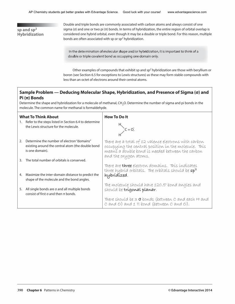
390 Chapter 6 Patterns in Chemistry © Edvantage Interactive 2014
sp and sp2 Hybridization
Double and triple bonds are commonly associated with carbon atoms and always consist of one sigma (σ) and one or two pi (π) bonds. In terms of hybridization, the entire region of orbital overlap is considered one hybrid orbital, even though it may be a double or triple bond. For this reason, multiple bonds are often associated with sp or sp2 hybridization.
In the determination of molecular shape and/or hybridization, it is important to think of a double or triple covalent bond as occupying one domain only.
Other examples of compounds that exhibit sp and sp2 hybridization are those with beryllium or boron (see Section 6.5 for exceptions to Lewis structures) as these may form stable compounds with less than an octet of electrons around their central atoms.
Sample Problem — Deducing Molecular Shape, Hybridization, and Presence of Sigma (σ) and Pi (π) BondsDetermine the shape and hybridization for a molecule of methanal, CH2O. Determine the number of sigma and pi bonds in the molecule. The common name for methanal is formaldehyde.
What To Think About1. Refer to the steps listed in Section 6.4 to determine
the Lewis structure for the molecule.
2. Determine the number of electron “domains” existing around the central atom (the double bond is one domain).
3. The total number of orbitals is conserved.
4. Maximize the inter-domain distance to predict the shape of the molecule and the bond angles.
5. All single bonds are σ and all multiple bonds consist of first σ and then π bonds.
How To Do It
�
������
There are a total of 12 valence electrons with carbon occupying the central position in the molecule. This means a double bond is needed between the carbon and the oxygen atoms.
There are three electron domains. This indicates three hybrid orbitals. The orbitals should be sp2 hybridized.
The molecule should have 120.5° bond angles and should be trigonal planar.
There should be 3 σ bonds (between C and each H and C and O) and 1 π bond (between C and O).
AP Chemistry students get better grades with Edvantage Science. Good luck with your course! www.edvantagescience.com
© Edvantage Interactive 2014 Chapter 6 Patterns in Chemistry 391
Practice Problems—Deducing Molecular Shape, Hybridization, and Presence of Sigma (σ) and Pi (π) Bonds1. Draw Lewis structures for each of the following species.
a) CH4 b) H3O+ c) OF2 d) HCN e) SF6 f ) SOF4
2. State the shape and the central atom hybridization for each of the structures.
3. Label each molecule as polar or non-polar.
AP Chemistry students get better grades with Edvantage Science. Good luck with your course! www.edvantagescience.com
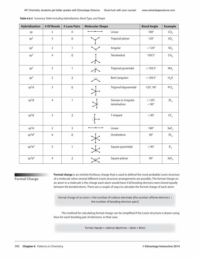
392 Chapter 6 Patterns in Chemistry © Edvantage Interactive 2014
Table 6.6.5 Summary Table Including Hybridization, Bond Type, and Shape
Hybridization # Of Bonds # Lone Pairs Molecular Shape Bond Angle Example
sp 2 0 Linear 180° CO2
sp2 3 0 Trigonal planar 120° SO3
sp2 2 1 . . Angular < 120° SO2
sp3 4 0 Tetrahedral 109.5° CH4
sp3 3 1 . . Trigonal pyramidal < 109.5° NH3
sp3 2 2 . . . . Bent (angular) < 109.5° H2O
sp3d 5 0 Trigonal bipyramidal 120°, 90° PCl5
sp3d 4 1. .
Seesaw or irregular tetrahedron
< 120°, < 90°
SF4
sp3d 3 2....
T-shaped < 90° CF3
sp3d 2 3 Linear 180° XeF2
sp3d2 6 0 Octahedron 90° SF8
sp3d2 5 1. .
Square pyramidal < 90° IF5
sp3d2 4 2. .. . Square planar 90° XeF4
Formal ChargeFormal charge is an entirely fictitious charge that is used to defend the most probable Lewis structure of a molecule when several different Lewis structure arrangements are possible. The formal charge on an atom in a molecule is the charge each atom would have if all bonding electrons were shared equally between the bonded atoms. There are a couple of ways to calculate the formal charge of each atom.
formal charge of an atom = the number of valence electrons [the number of lone electrons + the number of bonding electron pairs]
This method for calculating formal charge can be simplified if the Lewis structure is drawn using lines for each bonding pair of electrons. In that case:
formal charge = valence electrons – (dots + lines)
AP Chemistry students get better grades with Edvantage Science. Good luck with your course! www.edvantagescience.com
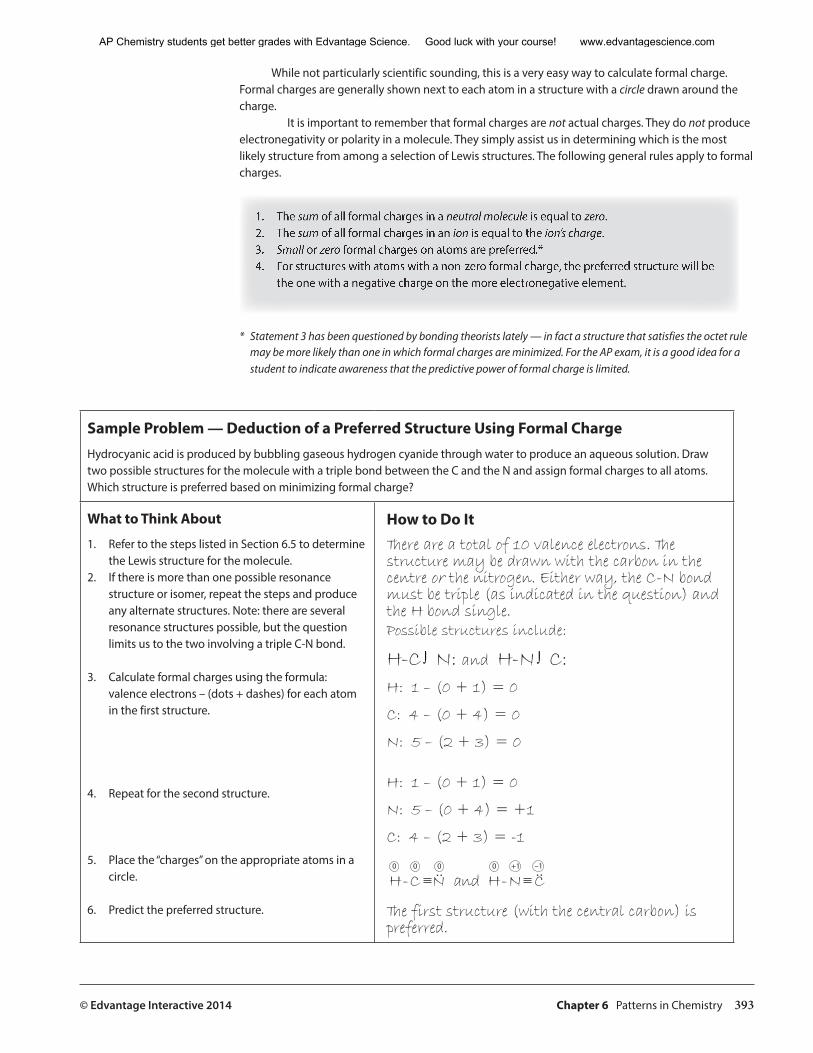
© Edvantage Interactive 2014 Chapter 6 Patterns in Chemistry 393
While not particularly scientific sounding, this is a very easy way to calculate formal charge. Formal charges are generally shown next to each atom in a structure with a circle drawn around the charge.
It is important to remember that formal charges are not actual charges. They do not produce electronegativity or polarity in a molecule. They simply assist us in determining which is the most likely structure from among a selection of Lewis structures. The following general rules apply to formal charges.
1. The sum of all formal charges in a neutral molecule is equal to zero.2. The sum of all formal charges in an ion is equal to the ion’s charge.3. Small or zero formal charges on atoms are preferred.*4. For structures with atoms with a non-zero formal charge, the preferred structure will be
the one with a negative charge on the more electronegative element.
* Statement 3 has been questioned by bonding theorists lately — in fact a structure that satisfies the octet rule may be more likely than one in which formal charges are minimized. For the AP exam, it is a good idea for a student to indicate awareness that the predictive power of formal charge is limited.
Sample Problem — Deduction of a Preferred Structure Using Formal ChargeHydrocyanic acid is produced by bubbling gaseous hydrogen cyanide through water to produce an aqueous solution. Draw two possible structures for the molecule with a triple bond between the C and the N and assign formal charges to all atoms. Which structure is preferred based on minimizing formal charge?
What to Think About
1. Refer to the steps listed in Section 6.5 to determine the Lewis structure for the molecule.
2. If there is more than one possible resonance structure or isomer, repeat the steps and produce any alternate structures. Note: there are several resonance structures possible, but the question limits us to the two involving a triple C-N bond.
3. Calculate formal charges using the formula: valence electrons – (dots + dashes) for each atom in the first structure.
4. Repeat for the second structure.
5. Place the “charges” on the appropriate atoms in a circle.
6. Predict the preferred structure.
How to Do ItThere are a total of 10 valence electrons. The structure may be drawn with the carbon in the centre or the nitrogen. Either way, the C-N bond must be triple (as indicated in the question) and the H bond single.Possible structures include:
H-C ∫ N: and H-N ∫ C:H: 1 – (0 + 1) = 0
C: 4 – (0 + 4) = 0
N: 5 – (2 + 3) = 0
H: 1 – (0 + 1) = 0
N: 5 – (0 + 4) = +1
C: 4 – (2 + 3) = -1
������������������������ � �� ��
The first structure (with the central carbon) is preferred.
AP Chemistry students get better grades with Edvantage Science. Good luck with your course! www.edvantagescience.com
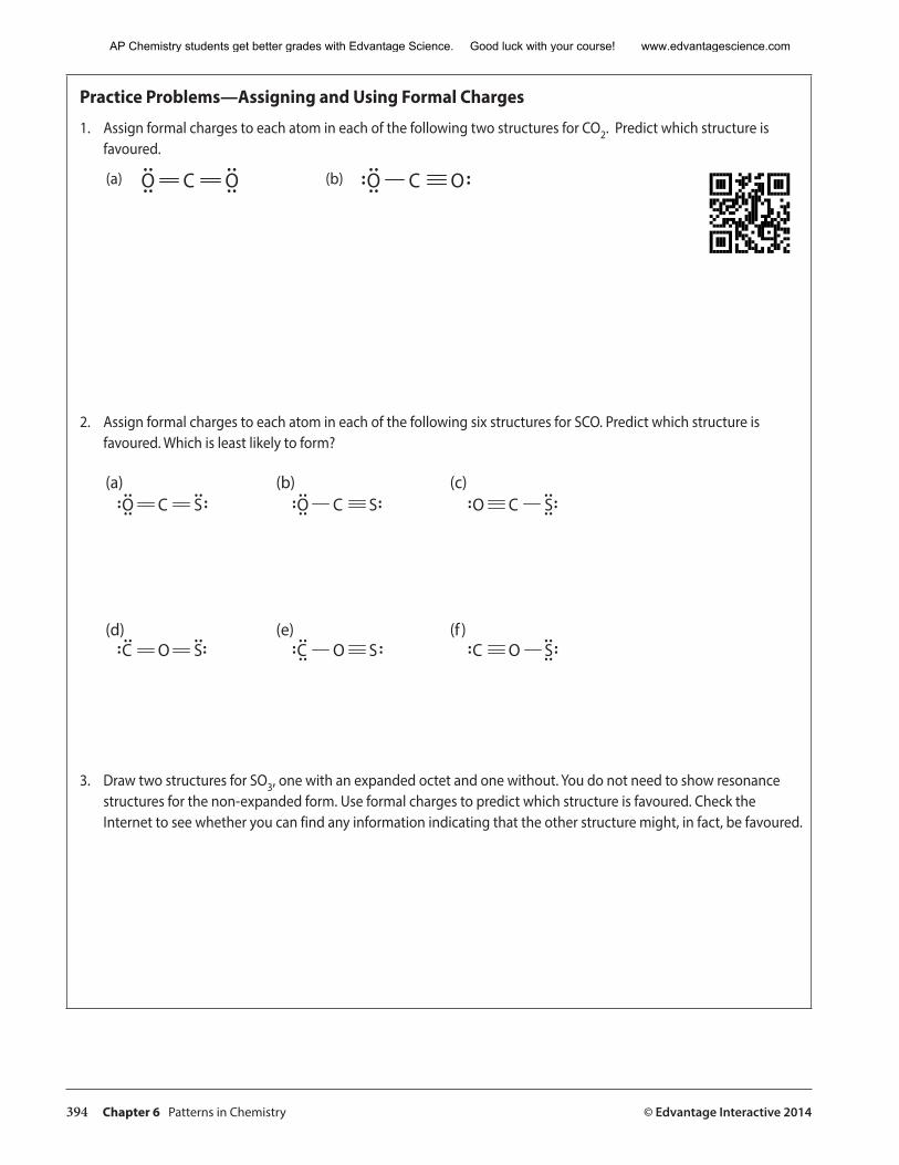
394 Chapter 6 Patterns in Chemistry © Edvantage Interactive 2014
Practice Problems—Assigning and Using Formal Charges
1. Assign formal charges to each atom in each of the following two structures for CO2. Predict which structure isfavoured.
� � � � � ���� ���
2. Assign formal charges to each atom in each of the following six structures for SCO. Predict which structure isfavoured. Which is least likely to form?
� � �� � � � � �
� � �� � � � � �
��� ��� ���
��� ��� �� �
3. Draw two structures for SO3, one with an expanded octet and one without. You do not need to show resonancestructures for the non-expanded form. Use formal charges to predict which structure is favoured. Check theInternet to see whether you can find any information indicating that the other structure might, in fact, be favoured.
AP Chemistry students get better grades with Edvantage Science. Good luck with your course! www.edvantagescience.com
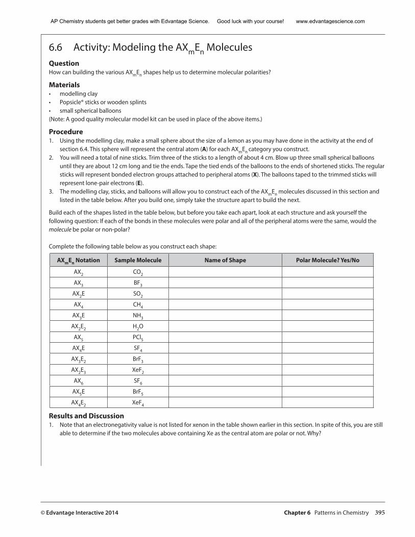
© Edvantage Interactive 2014 Chapter 6 Patterns in Chemistry 395
6.6 Activity: Modeling the AXmEn Molecules QuestionHow can building the various AXmEn shapes help us to determine molecular polarities?
Materials• modelling clay• Popsicle® sticks or wooden splints• small spherical balloons(Note: A good quality molecular model kit can be used in place of the above items.)
Procedure1. Using the modelling clay, make a small sphere about the size of a lemon as you may have done in the activity at the end of
section 6.4. This sphere will represent the central atom (A) for each AXmEn category you construct.2. You will need a total of nine sticks. Trim three of the sticks to a length of about 4 cm. Blow up three small spherical balloons
until they are about 12 cm long and tie the ends. Tape the tied ends of the balloons to the ends of shortened sticks. The regular sticks will represent bonded electron groups attached to peripheral atoms (X). The balloons taped to the trimmed sticks will represent lone-pair electrons (E).
3. The modelling clay, sticks, and balloons will allow you to construct each of the AXmEn molecules discussed in this section and listed in the table below. After you build one, simply take the structure apart to build the next.
Build each of the shapes listed in the table below, but before you take each apart, look at each structure and ask yourself the following question: If each of the bonds in these molecules were polar and all of the peripheral atoms were the same, would the molecule be polar or non-polar?
Complete the following table below as you construct each shape:
AXmEn Notation Sample Molecule Name of Shape Polar Molecule? Yes/No
AX2 CO2
AX3 BF3
AX2E SO2
AX4 CH4
AX3E NH3
AX2E2 H2O
AX5 PCl5AX4E SF4
AX3E2 BrF3
AX2E3 XeF2
AX6 SF6
AX5E BrF5
AX4E2 XeF4
Results and Discussion1. Note that an electronegativity value is not listed for xenon in the table shown earlier in this section. In spite of this, you are still
able to determine if the two molecules above containing Xe as the central atom are polar or not. Why?
AP Chemistry students get better grades with Edvantage Science. Good luck with your course! www.edvantagescience.com
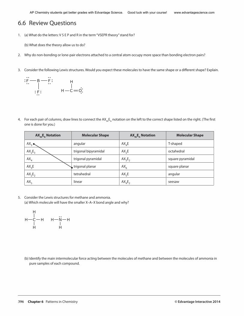
396 Chapter 6 Patterns in Chemistry © Edvantage Interactive 2014
6.6 Review Questions
1. (a) What do the letters: V S E P and R in the term “VSEPR theory” stand for?
(b) What does the theory allow us to do?
2. Why do non-bonding or lone-pair electrons attached to a central atom occupy more space than bonding electron pairs?
3. Consider the following Lewis structures. Would you expect these molecules to have the same shape or a different shape? Explain.
B
F
F F
H OC
H
4. For each pair of columns, draw lines to connect the AXmEn notation on the left to the correct shape listed on the right. (The first one is done for you.)
AXmEn Notation Molecular Shape AXmEn Notation Molecular Shape
AX3 angular AX4E T-shaped
AX2E3 trigonal bipyramidal AX2E octahedral
AX4 trigonal pyramidal AX3E2 square pyramidal
AX3E trigonal planar AX6 square planar
AX2E2 tetrahedral AX5E angular
AX5 linear AX4E2 seesaw
5. Consider the Lewis structures for methane and ammonia. (a) Which molecule will have the smaller X–A–X bond angle and why?
H
H
C
H
H H N
H
H
(b) Identify the main intermolecular force acting between the molecules of methane and between the molecules of ammonia in pure samples of each compound.
AP Chemistry students get better grades with Edvantage Science. Good luck with your course! www.edvantagescience.com
© Edvantage Interactive 2014 Chapter 6 Patterns in Chemistry 397
6. Assume that all of the peripheral atoms are the same for each AXmEn category listed below and complete the following table. (Note that two different bond angles exist in an AX5 molecule.)
AXmEn Category AX2 AX3 AX4 AX5 AX2E3 AX6 AX4E2
X–A–X Bond Angle
7. Consider the following group 17 binary hydrides: HI, HBr, HCl, and HF. Which should have the highest boiling point and why?
8. The industrial production of ammonia, NH3, from H2 and N2 is called the Haber process, named for Fritz Haber, the German chemist who developed it just before World War I. During the process, in a gaseous mixture of all three substances, NH3 must be separated from H2 and N2. This is done by cooling the gaseous mixture so as to condense only the NH3. This leaves the elemental nitrogen and hydrogen as gases to be recycled and produce more ammonia. Why does only the ammonia liquefy upon cooling, but not the H2 or N2?
9. Identify two examples of how hydrogen bonding between molecules makes life on Earth possible.
10. Iodine is a non-polar diatomic molecule, yet its molecules have enough attraction for each other that the element exists as a solid at room temperature. Identify the attractive force and explain why it is strong enough to keep the molecules of I2 attached to each other even at room temperature.
11. Ionic compounds such as NaCl have very high melting points because a great deal of energy is required to overcome the many attractive forces between the oppositely charged ions in an ionic crystal lattice. NaCl melts at 801°C, yet its ions will readily separate from each other at room temperature when the solid is added to water. Explain this by discussing the predominant force that allows an ionic compound to dissolve in water.
AP Chemistry students get better grades with Edvantage Science. Good luck with your course! www.edvantagescience.com
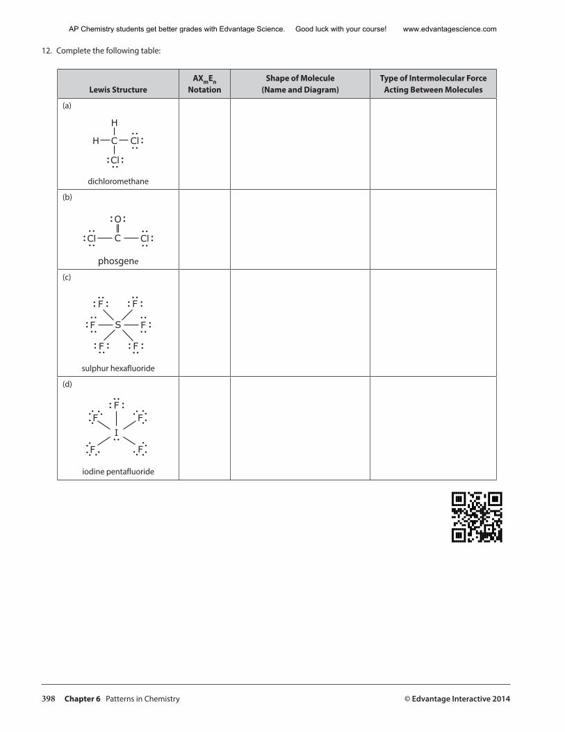
398 Chapter 6 Patterns in Chemistry © Edvantage Interactive 2014
12. Complete the following table:
Lewis StructureAXmEn
NotationShape of Molecule
(Name and Diagram)Type of Intermolecular Force
Acting Between Molecules
(a)
H
H
C
Cl
Cl
dichloromethane
(b)
CCl Cl
O
phosgene
(c)
F
SF F
F
FF
sulphur hexafluoride
(d)
FI
F
FF
F
iodine pentafluoride
AP Chemistry students get better grades with Edvantage Science. Good luck with your course! www.edvantagescience.com
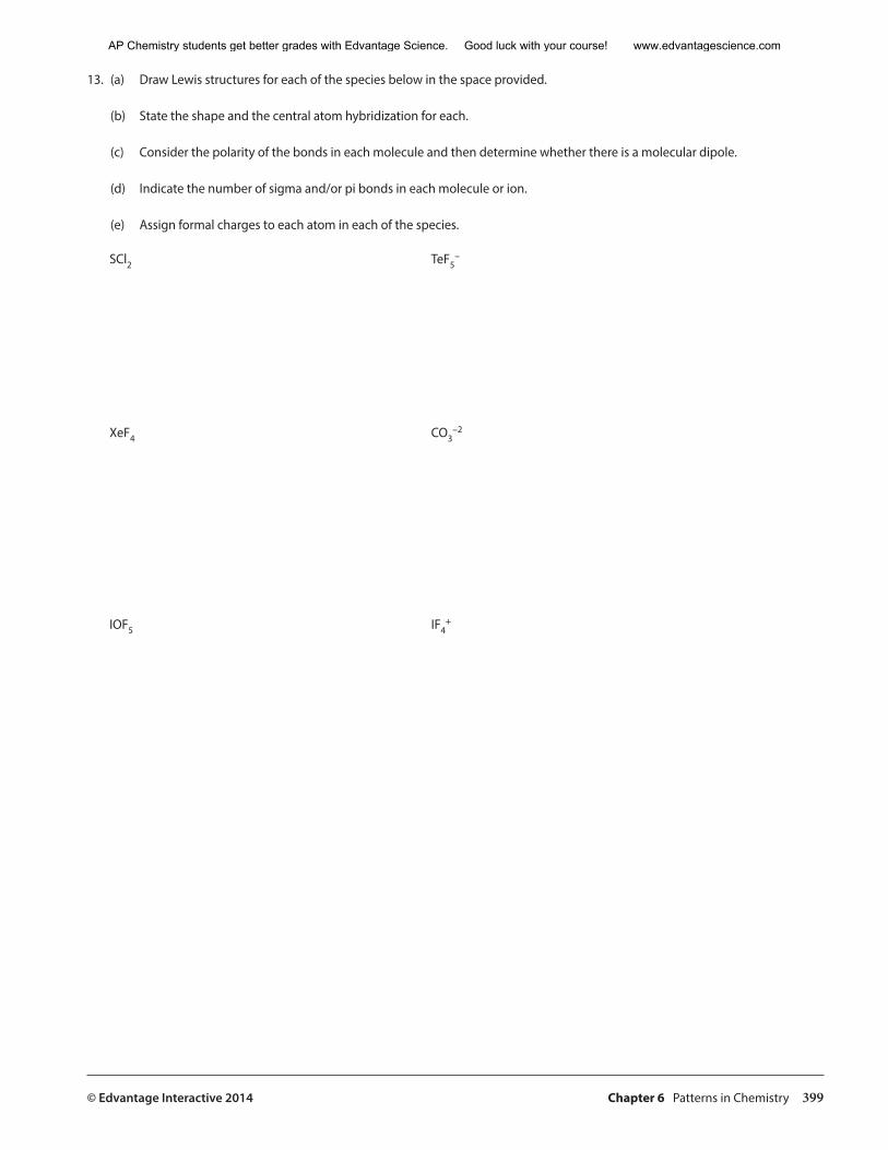
© Edvantage Interactive 2014 Chapter 6 Patterns in Chemistry 399
13. (a) Draw Lewis structures for each of the species below in the space provided.
(b) State the shape and the central atom hybridization for each.
(c) Consider the polarity of the bonds in each molecule and then determine whether there is a molecular dipole.
(d) Indicate the number of sigma and/or pi bonds in each molecule or ion.
(e) Assign formal charges to each atom in each of the species.
SCl2 TeF5−
XeF4 CO3−2
IOF5 IF4+
AP Chemistry students get better grades with Edvantage Science. Good luck with your course! www.edvantagescience.com
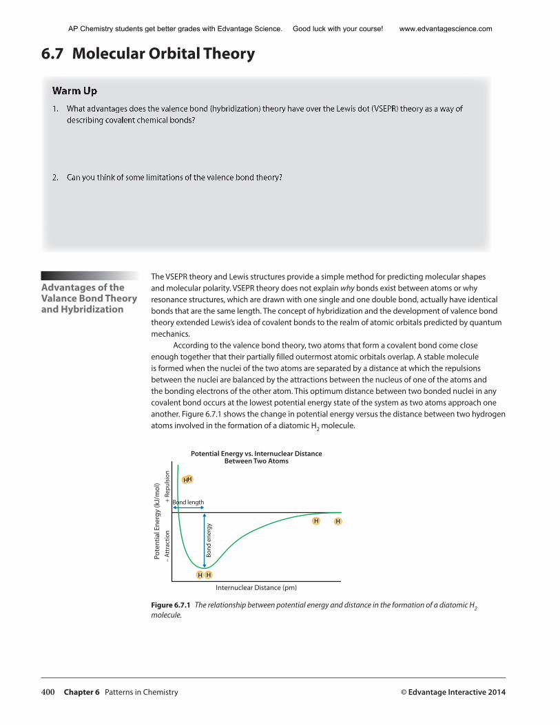
400 Chapter 6 Patterns in Chemistry © Edvantage Interactive 2014
6.7 Molecular Orbital Theory
Warm Up1. What advantages does the valence bond (hybridization) theory have over the Lewis dot (VSEPR) theory as a way of
describing covalent chemical bonds?
2. Can you think of some limitations of the valence bond theory?
Advantages of the Valance Bond Theory and Hybridization
The VSEPR theory and Lewis structures provide a simple method for predicting molecular shapes and molecular polarity. VSEPR theory does not explain why bonds exist between atoms or why resonance structures, which are drawn with one single and one double bond, actually have identical bonds that are the same length. The concept of hybridization and the development of valence bond theory extended Lewis’s idea of covalent bonds to the realm of atomic orbitals predicted by quantum mechanics.
According to the valence bond theory, two atoms that form a covalent bond come close enough together that their partially filled outermost atomic orbitals overlap. A stable molecule is formed when the nuclei of the two atoms are separated by a distance at which the repulsions between the nuclei are balanced by the attractions between the nucleus of one of the atoms and the bonding electrons of the other atom. This optimum distance between two bonded nuclei in any covalent bond occurs at the lowest potential energy state of the system as two atoms approach one another. Figure 6.7.1 shows the change in potential energy versus the distance between two hydrogen atoms involved in the formation of a diatomic H2 molecule.
������������������������������������������������������������
��������������������������
����
�������
����
�������
���
�����
������
������������
����
����
���
�����������
��
� �
� �
Figure 6.7.1 The relationship between potential energy and distance in the formation of a diatomic H2 molecule.
AP Chemistry students get better grades with Edvantage Science. Good luck with your course! www.edvantagescience.com
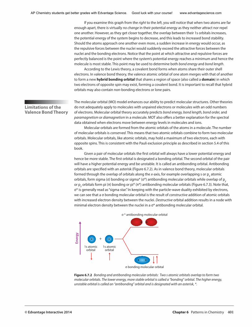
© Edvantage Interactive 2014 Chapter 6 Patterns in Chemistry 401
If you examine this graph from the right to the left, you will notice that when two atoms are far enough apart, there is virtually no change in their potential energy as they neither attract nor repel one another. However, as they get closer together, the overlap between their 1s orbitals increases, the potential energy of the system begins to decrease, and this leads to increased bond stability. Should the atoms approach one another even more, a sudden increase in energy would occur, as the repulsive forces between the nuclei would suddenly exceed the attractive forces between the nuclei and the bonding electrons. Notice that the point at which attractive and repulsive forces are perfectly balanced is the point where the system’s potential energy reaches a minimum and hence the molecule is most stable. This point may be used to determine both bond energy and bond length.
According to the Lewis theory, a covalent bond forms when atoms share their outer shell electrons. In valence bond theory, the valence atomic orbital of one atom merges with that of another to form a new hybrid bonding orbital that shares a region of space (also called a domain) in which two electrons of opposite spin may exist, forming a covalent bond. It is important to recall that hybrid orbitals may also contain non-bonding electrons or lone pairs.
Limitations of the Valence Bond Theory
The molecular orbital (MO) model enhances our ability to predict molecular structures. Other theories do not adequately apply to molecules with unpaired electrons or molecules with an odd numbers of electrons. Molecular orbital theory accurately predicts bond energy, bond length, bond order, and paramagnetism or diamagnetism in a molecule. MOT also offers a better explanation for the spectral data obtained when electrons move between energy levels in molecules and ions.
Molecular orbitals are formed from the atomic orbitals of the atoms in a molecule. The number of molecular orbitals is conserved. This means that two atomic orbitals combine to form two molecular orbitals. Molecular orbitals, like atomic orbitals, may hold a maximum of two electrons, each with opposite spins. This is consistent with the Pauli exclusion principle as described in section 5.4 of this book.
Given a pair of molecular orbitals the first orbital will always have a lower potential energy and hence be more stable. The first orbital is designated a bonding orbital. The second orbital of the pair will have a higher potential energy and be unstable. It is called an antibonding orbital. Antibonding orbitals are specified with an asterisk (Figure 6.7.2). As in valence bond theory, molecular orbitals formed through the overlap of orbitals along the x-axis, for example overlapping s or px atomic orbitals, form sigma (σ) bonding or sigma* (σ*) antibonding molecular orbitals while overlap of py or pz orbitals form pi (π) bonding or pi* (π*) antibonding molecular orbitals (Figure 6.7.3). Note that, σ* is generally read as “sigma star.” In keeping with the particle-wave duality exhibited by electrons, we can see that a σ bonding molecular orbital is the result of constructive addition of atomic orbitals with increased electron density between the nuclei. Destructive orbital addition results in a node with minimal electron density between the nuclei in a σ* antibonding molecular orbital.
���������������������������������
���������������������������
�����������������
�����������������
�
������
Figure 6.7.2 Bonding and antibonding molecular orbitals: Two s atomic orbitals overlap to form two molecular orbitals. The lower energy, more stable orbital is called a “bonding” orbital. The higher energy, unstable orbital is called an “antibonding” orbital and is designated with an asterisk, *.
AP Chemistry students get better grades with Edvantage Science. Good luck with your course! www.edvantagescience.com
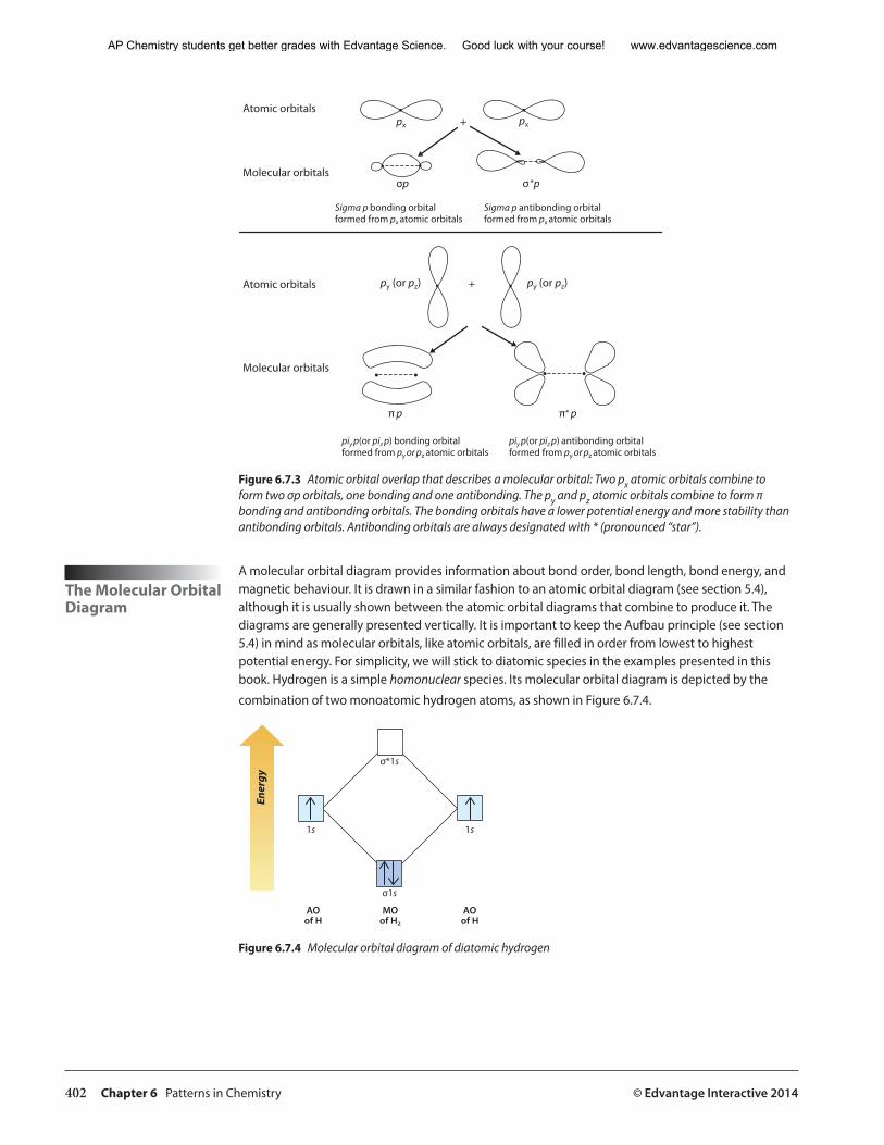
402 Chapter 6 Patterns in Chemistry © Edvantage Interactive 2014
���������������
������������������
���������������
������������������
��
���������� ����������
��� ����
�� ���
�
�
��
������������������������������������������������������
����������������������������������������������������������
��������������������������������������������������������������������
������������������������������������������������������������������������
Figure 6.7.3 Atomic orbital overlap that describes a molecular orbital: Two px atomic orbitals combine to form two σp orbitals, one bonding and one antibonding. The py and pz atomic orbitals combine to form π bonding and antibonding orbitals. The bonding orbitals have a lower potential energy and more stability than antibonding orbitals. Antibonding orbitals are always designated with * (pronounced “star”).
The Molecular Orbital Diagram
A molecular orbital diagram provides information about bond order, bond length, bond energy, and magnetic behaviour. It is drawn in a similar fashion to an atomic orbital diagram (see section 5.4), although it is usually shown between the atomic orbital diagrams that combine to produce it. The diagrams are generally presented vertically. It is important to keep the Aufbau principle (see section 5.4) in mind as molecular orbitals, like atomic orbitals, are filled in order from lowest to highest potential energy. For simplicity, we will stick to diatomic species in the examples presented in this book. Hydrogen is a simple homonuclear species. Its molecular orbital diagram is depicted by the
combination of two monoatomic hydrogen atoms, as shown in Figure 6.7.4.
������
�� ��
���
����
������
�������
������
Figure 6.7.4 Molecular orbital diagram of diatomic hydrogen
AP Chemistry students get better grades with Edvantage Science. Good luck with your course! www.edvantagescience.com
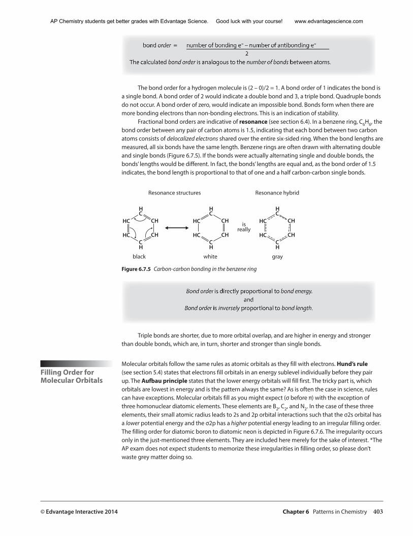
© Edvantage Interactive 2014 Chapter 6 Patterns in Chemistry 403
bond order = number of bonding e– – number of antibonding e–
2The calculated bond order is analogous to the number of bonds between atoms.
The bond order for a hydrogen molecule is (2 – 0)/2 = 1. A bond order of 1 indicates the bond is a single bond. A bond order of 2 would indicate a double bond and 3, a triple bond. Quadruple bonds do not occur. A bond order of zero, would indicate an impossible bond. Bonds form when there are more bonding electrons than non-bonding electrons. This is an indication of stability.
Fractional bond orders are indicative of resonance (see section 6.4). In a benzene ring, C6H6, the bond order between any pair of carbon atoms is 1.5, indicating that each bond between two carbon atoms consists of delocalized electrons shared over the entire six-sided ring. When the bond lengths are measured, all six bonds have the same length. Benzene rings are often drawn with alternating double and single bonds (Figure 6.7.5). If the bonds were actually alternating single and double bonds, the bonds’ lengths would be different. In fact, the bonds’ lengths are equal and, as the bond order of 1.5 indicates, the bond length is proportional to that of one and a half carbon-carbon single bonds.
��������������������
����� ����� ����
���������
����������������
�
�
�
�
����
����
�
�
�
�
����
����
�
�
�
�
����
����
Figure 6.7.5 Carbon-carbon bonding in the benzene ring
Bond order is directly proportional to bond energy.and
Bond order is inversely proportional to bond length.
Triple bonds are shorter, due to more orbital overlap, and are higher in energy and stronger than double bonds, which are, in turn, shorter and stronger than single bonds.
Filling Order for Molecular Orbitals
Molecular orbitals follow the same rules as atomic orbitals as they fill with electrons. Hund’s rule (see section 5.4) states that electrons fill orbitals in an energy sublevel individually before they pair up. The Aufbau principle states that the lower energy orbitals will fill first. The tricky part is, which orbitals are lowest in energy and is the pattern always the same? As is often the case in science, rules can have exceptions. Molecular orbitals fill as you might expect (σ before π) with the exception of three homonuclear diatomic elements. These elements are B2, C2, and N2. In the case of these three elements, their small atomic radius leads to 2s and 2p orbital interactions such that the σ2s orbital has a lower potential energy and the σ2p has a higher potential energy leading to an irregular filling order. The filling order for diatomic boron to diatomic neon is depicted in Figure 6.7.6. The irregularity occurs only in the just-mentioned three elements. They are included here merely for the sake of interest. *The AP exam does not expect students to memorize these irregularities in filling order, so please don’t waste grey matter doing so.
AP Chemistry students get better grades with Edvantage Science. Good luck with your course! www.edvantagescience.com
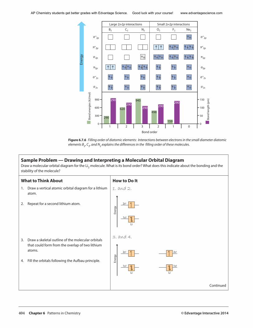
404 Chapter 6 Patterns in Chemistry © Edvantage Interactive 2014
������������������������ ������������������������
�� �� �� �� �� ���
hihi hihi
hi
hihihihihihi
hihi hihi
hi
hi hi hi
hi hi hi
hi hi hihi hi hi
hi hi hi
h h
h h
� �� �� �� �� �� �
����
����
�����������
���
����
�����
�����
��
����������
���
���
���
�
���
���
��
�
���
������
��� ������
���
���
���
���
����
����
���
���
����
���
����
����
���
���
����
���
����
��
Figure 6.7.6 Filling order of diatomic elements: Interactions between electrons in the small diameter diatomic elements B2, C2, and N2 explains the differences in the filling order of these molecules.
Sample Problem — Drawing and Interpreting a Molecular Orbital DiagramDraw a molecular orbital diagram for the Li2 molecule. What is its bond order? What does this indicate about the bonding and the stability of the molecule?
What to Think About
1. Draw a vertical atomic orbital diagram for a lithium atom.
2. Repeat for a second lithium atom.
3. Draw a skeletal outline of the molecular orbitals that could form from the overlap of two lithium atoms.
4. Fill the orbitals following the Aufbau principle.
How to Do It
1. and 2.
����
��
���
���
��
3. and 4.
����
��
���
���
��
���
���
��
Continued
AP Chemistry students get better grades with Edvantage Science. Good luck with your course! www.edvantagescience.com
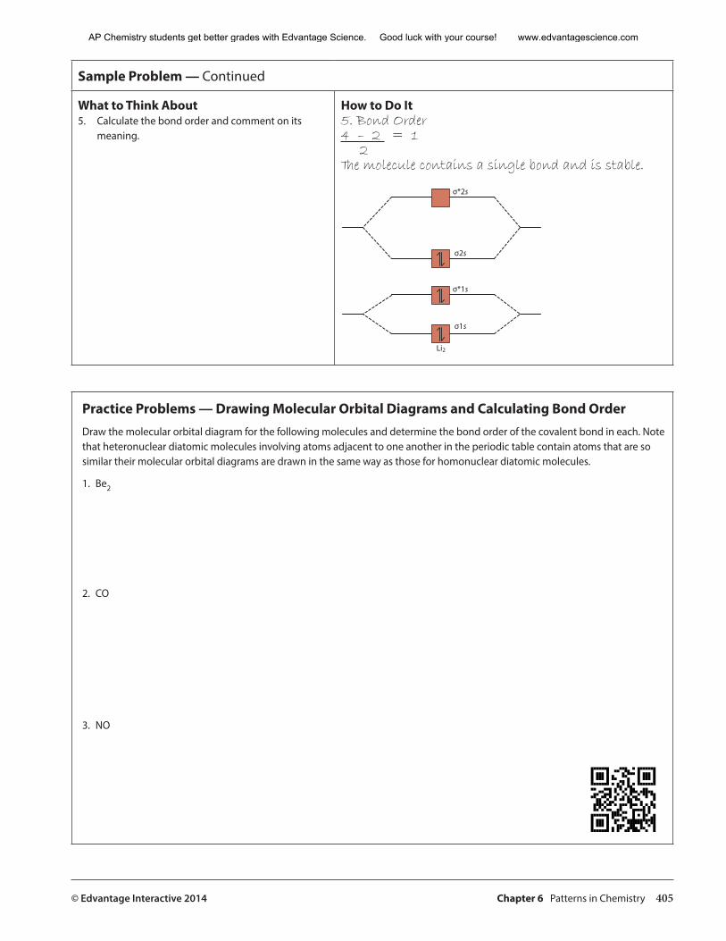
© Edvantage Interactive 2014 Chapter 6 Patterns in Chemistry 405
Sample Problem — Continued
What to Think About5. Calculate the bond order and comment on its
meaning.
How to Do It5. Bond Order4 – 2 = 1 2The molecule contains a single bond and is stable.
����
���
����
���
���
Practice Problems — Drawing Molecular Orbital Diagrams and Calculating Bond OrderDraw the molecular orbital diagram for the following molecules and determine the bond order of the covalent bond in each. Note that heteronuclear diatomic molecules involving atoms adjacent to one another in the periodic table contain atoms that are so similar their molecular orbital diagrams are drawn in the same way as those for homonuclear diatomic molecules.
1. Be2
2. CO
3. NO
AP Chemistry students get better grades with Edvantage Science. Good luck with your course! www.edvantagescience.com
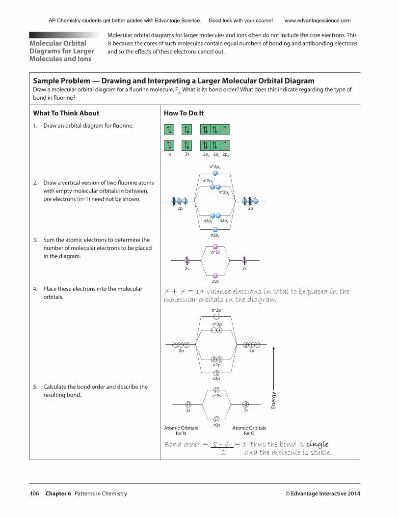
406 Chapter 6 Patterns in Chemistry © Edvantage Interactive 2014
Molecular Orbital Diagrams for Larger Molecules and Ions
Molecular orbital diagrams for larger molecules and ions often do not include the core electrons. This is because the cores of such molecules contain equal numbers of bonding and antibonding electrons and so the effects of these electrons cancel out.
Sample Problem — Drawing and Interpreting a Larger Molecular Orbital DiagramDraw a molecular orbital diagram for a fluorine molecule, F2. What is its bond order? What does this indicate regarding the type of bond in fluorine?
What To Think About
1. Draw an orbital diagram for fluorine.
2. Draw a vertical version of two fluorine atoms with empty molecular orbitals in between.ore electrons (n=1) need not be shown.
3. Sum the atomic electrons to determine the number of molecular electrons to be placed in the diagram.
4. Place these electrons into the molecular orbitals.
5. Calculate the bond order and describe the resulting bond.
How To Do It
�� �� ��� ��� ���
�����
����
���
����
�� ��
�� ��
�����
����
�����
����
7 + 7 = 14 valence electrons in total to be placed in the molecular orbitals in the diagram
����
����
���
�� ��
�� ��
����
���
���
����
��
���������������������
���������������������
Bond order = 8 – 6 = 1 thus the bond is single2 and the molecule is stable.
AP Chemistry students get better grades with Edvantage Science. Good luck with your course! www.edvantagescience.com
© Edvantage Interactive 2014 Chapter 6 Patterns in Chemistry 407
Molecular orbital diagrams for ions are drawn in the same way as uncharged molecules except that electrons are added or removed from the molecular orbitals to account for the ion’s charge.
Quick Check 1. Draw a Lewis diagram of the ions NO– and NO+.
2. Draw MO diagrams of the ions NO– and NO+.
3. Calculate the bond order for the uncharged molecule and each of the ions. Compare types of bond, their strengths and their lengths for the two ions.
4. How do the bonds predicted by the Lewis structures compare to those predicted by MO theory?
ParamagnetismOne of the first problems that surfaced with the valence bond theory was its inability to properly predict paramagnetism. Substances that are paramagnetic are attracted to a magnetic field. Substances that are not paramagnetic are diamagnetic. Diamagnetic substances are weakly repelled by a magnetic field.
Paramagnetic substances are attracted to a magnetic field due to the presence of unpaired electrons in their electronic configuration.
AP Chemistry students get better grades with Edvantage Science. Good luck with your course! www.edvantagescience.com

408 Chapter 6 Patterns in Chemistry © Edvantage Interactive 2014
Quick Check1. Draw a Lewis structure for O2 gas.
2. Draw a molecular orbital diagram for O2 gas.
3. Which of the species in the Practice Problems on page 405 are diamagnetic? What about the ions in the Quick Check on page 407?
Molecular Models: A Summary
In sections 6.3 through 6.6, we have examined a variety of models that describe the bonding that occurs in covalent molecules. Lewis structures provide a foundation for understanding covalent bonds. VSEPR and valence bond theory explain how electrons in hybridized orbitals repel one another to produce different molecular geometries. Molecular orbital theory provides more insight into the stability of covalent bonds. The behaviour of coordination compounds containing partially filled d-orbital electrons require yet another bonding theory called crystal field theory in which the normally degenerate d orbitals split into different energies depending on the spatial orientation of these orbitals. Movement of electrons between these different energy d orbitals manifests a variety of beautiful colours in coordination compounds. It is important to remember that all of these descriptions of the bonding in molecules and ions are models. No model is perfect, but each has something to contribute to our understanding of chemical bonding.
AP Chemistry students get better grades with Edvantage Science. Good luck with your course! www.edvantagescience.com
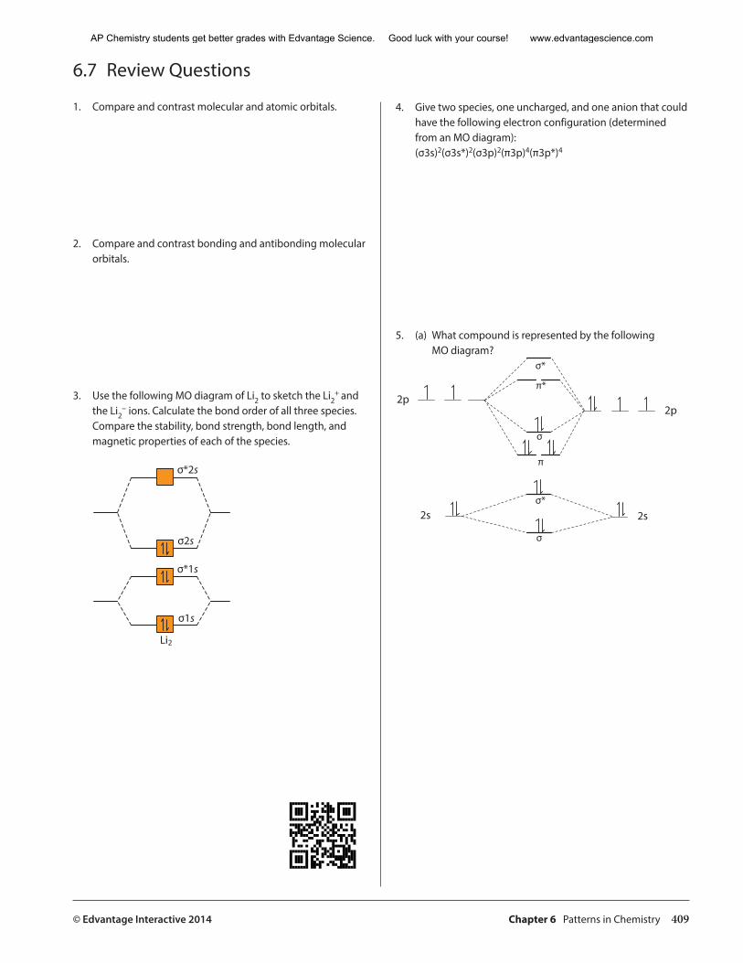
© Edvantage Interactive 2014 Chapter 6 Patterns in Chemistry 409
6.7 Review Questions
1. Compare and contrast molecular and atomic orbitals.
2. Compare and contrast bonding and antibonding molecular orbitals.
3. Use the following MO diagram of Li2 to sketch the Li2+ and
the Li2− ions. Calculate the bond order of all three species.
Compare the stability, bond strength, bond length, and magnetic properties of each of the species.
����
����
���
���
���
4. Give two species, one uncharged, and one anion that could have the following electron configuration (determined from an MO diagram):
(σ3s)2(σ3s*)2(σ3p)2(π3p)4(π3p*)4
5. (a) What compound is represented by the following MO diagram?
��
��
��
��
��
��
�
�
�
��
AP Chemistry students get better grades with Edvantage Science. Good luck with your course! www.edvantagescience.com
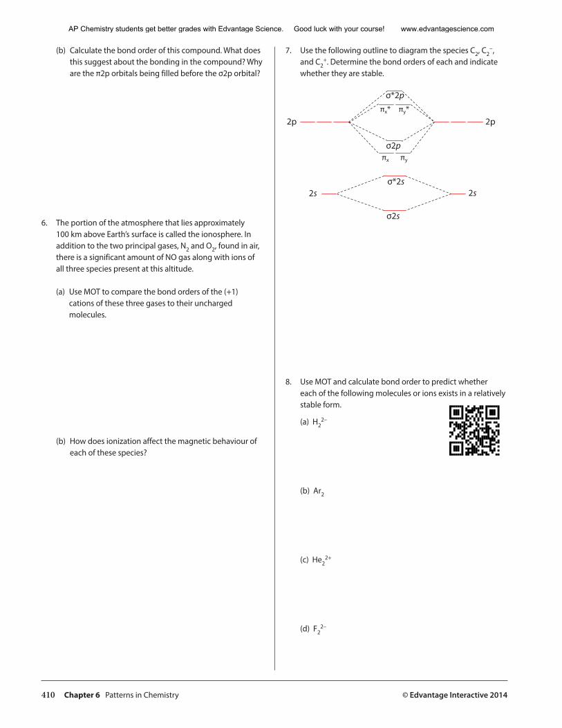
410 Chapter 6 Patterns in Chemistry © Edvantage Interactive 2014
(b) Calculate the bond order of this compound. What does this suggest about the bonding in the compound? Why are the π2p orbitals being filled before the σ2p orbital?
6. The portion of the atmosphere that lies approximately 100 km above Earth’s surface is called the ionosphere. In addition to the two principal gases, N2 and O2, found in air, there is a significant amount of NO gas along with ions of all three species present at this altitude.
(a) Use MOT to compare the bond orders of the (+1) cations of these three gases to their uncharged molecules.
(b) How does ionization affect the magnetic behaviour of each of these species?
7. Use the following outline to diagram the species C2, C2−,
and C2+. Determine the bond orders of each and indicate
whether they are stable.
�� ��
�� ��
���
����
����
���
��� ���
�� ��
8. Use MOT and calculate bond order to predict whether each of the following molecules or ions exists in a relatively stable form.
(a) H22–
(b) Ar2
(c) He22+
(d) F22–
AP Chemistry students get better grades with Edvantage Science. Good luck with your course! www.edvantagescience.com
Related Documents