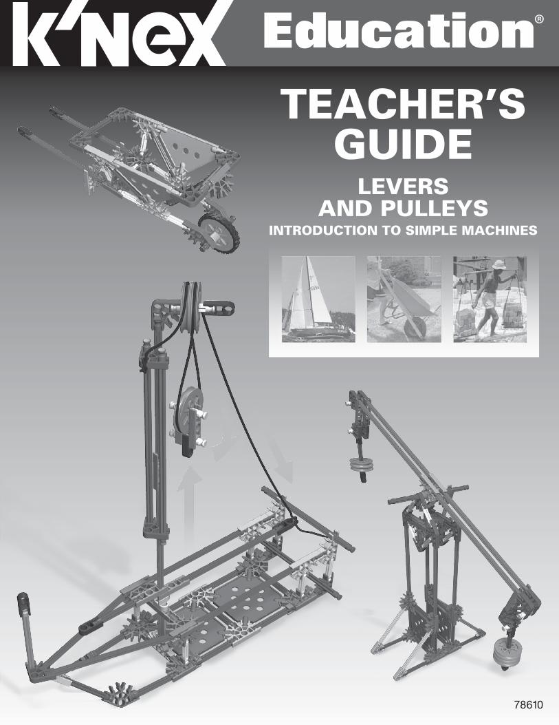
78610 TEACHER’S GUIDE LEVERS AND PULLEYS INTRODUCTION TO SIMPLE MACHINES Education ®

Welcome message from author
This document is posted to help you gain knowledge. Please leave a comment to let me know what you think about it! Share it to your friends and learn new things together.
Transcript
78610
TEACHER’SGUIDE
LEVERS AND PULLEYS
INTRODUCTION TO SIMPLE MACHINES
Education®

INTRODUCTION�TO�SIMPLE�MACHINES
www.knexeducat ion.com
LEVERS AND PULLEYSTeacher’s Guide
V3-8/14©2014 K’NEX Limited Partnership Group and its licensors.
K’NEX Limited Partnership GroupP.O. Box 700Hatfield, PA 19440-0700
K’NEX Education is a registered trademark of K’NEX Limited Partnership Group.Protected by International Copyright. All rights reserved.
Visit our website at www.knexeducation.comEmail: [email protected]: 1-888-ABC-KNEX (Toll Free)
A NOTE ABOUT SAFETY:Safety is of primary concern in science and technology classrooms. It is recommended that you develop a set of rules that governs the safe, proper use of K’NEX in your classroom. Safety, as it relates to the use of the Rubber Bands should be specifically addressed.
CAUTIONS:Students should not overstretch or overwind their Rubber Bands. Overstretching and overwinding can cause the Rubber Band to snap and cause personal injury. Any wear and tear or deterioration of Rubber Bands should be reported immediately to the teacher. Teachers and students should inspect Rubber Bands for deterioration before each experiment.
Caution students to keep hands and hair away from all moving parts. Never put fingers in moving Gears or other moving parts.
Education®
WARNING:CHOKING HAZARD – Small parts. Not for children under 3 years.
ATTENTION :RISQUE D’ÉTOUFFEMENT – Pièces de petite taille. Ne convient pas aux enfants de moins de 3 ans.
Introduction:
1
OVERVIEWThis Teacher’s Guide has been developed to support you as your students investigate the K’NEX Introduction to Simple Machines: Levers and Pulleys set. In conjunction with the K’NEX materials and individual Student Journals, the information and resources included here can be used to build your students’ understanding of scientific concepts and channel their inquiries into active and meaningful learning experiences.
K’NEX INTRO TO SIMPLE MACHINES: Levers and Pulleys. As part of a series, this K’NEX construction set is designed to introduce students to the scientific concepts associated with two types of Simple Machines – levers and pulleys. Students are provided with the opportunity to acquire skills using a hands-on, inquiry-based approach to information and concepts. Working cooperatively, students are encouraged to interact with each other as they build, investigate, discuss, and evaluate scientific principles in action.
TEACHER’S GUIDE. Designed as a resource for the teacher, this guide provides a glossary of key terms and definitions, includes an overview of the concepts associated with levers and pulleys, identifies student objectives for each unit, and offers plans and scripts to successfully present each simple machine model and its associated activities. Most of the units can be completed in 30-45 minutes. There are also extension activities that can be used to explore the concepts more deeply. We recommend that teachers review their curriculum and science education standards to identify which of the activities provided in this guide best meet their needs.
STUDENT JOURNALS. It is expected that students will always have journals available for recording information. They should be encouraged to enter initial thoughts at the start of an inquiry – what they “think” will happen. These initial thoughts may be amended, based on their ongoing inquiry and analysis, until the students feel comfortable about drawing conclusions. Their journal entries will help make a connection between the models they have built, the experiments they have conducted, and how this information is applied to the real-world machines they use on a regular basis. The journals will also provide students with a place to practice making drawings and diagrams of systems. Finally, the journals will serve as a method of assessment for the Simple Machines unit. Journal Checklists are also included in the Teacher’s Guide for each model and it’s associated inquiry activities.
TABLE OF CONTENTS
Levers ..................................................................................................................................................... 3-38
Objectives ............................................................................................................................................................... 3
Key Terms & Definitions .................................................................................................................................... 3-4
Key Concepts ..................................................................................................................................................... 4-11
Seesaw ............................................................................................................................................................. 13-20
Balance ............................................................................................................................................................ 21-25
Wheelbarrow ................................................................................................................................................... 27-30
Hockey Stick ................................................................................................................................................... 31-34
Scissors ............................................................................................................................................................ 35-38
Pulleys .................................................................................................................................................. 39-60
Objectives ............................................................................................................................................................. 39
Key Terms & Definitions ................................................................................................................................. 39-40
Key Concepts ................................................................................................................................................... 40-42
Flag Pole .......................................................................................................................................................... 43-47
Sailboat ............................................................................................................................................................ 49-53
Block and Tackle ............................................................................................................................................. 54-60
LEVERS�AND�PULLEYS
www.knexeducat ion.com Education®
2
Wheels & AxlesLeversBackground Information
3
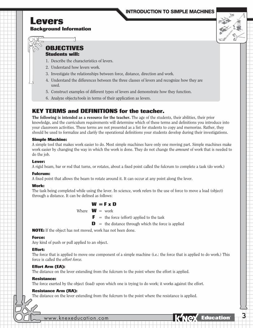
KEY TERMS and DEFINITIONS for the teacher. The following is intended as a resource for the teacher. The age of the students, their abilities, their prior knowledge, and the curriculum requirements will determine which of these terms and definitions you introduce into your classroom activities. These terms are not presented as a list for students to copy and memorize. Rather, they should be used to formalize and clarify the operational definitions your students develop during their investigations.
Simple Machine: A simple tool that makes work easier to do. Most simple machines have only one moving part. Simple machines make work easier by changing the way in which the work is done. They do not change the amount of work that is needed to do the job.
Lever: A rigid beam, bar or rod that turns, or rotates, about a fixed point called the fulcrum to complete a task (do work.)
Fulcrum: A fixed point that allows the beam to rotate around it. It can occur at any point along the lever.
Work: The task being completed while using the lever. In science, work refers to the use of force to move a load (object) through a distance. It can be defined as follows:
W = F x D Where W = work
F = the force (effort) applied to the task
D = the distance through which the force is applied
NOTE: If the object has not moved, work has not been done.
Force: Any kind of push or pull applied to an object.
Effort: The force that is applied to move one component of a simple machine (i.e.: the force that is applied to do work.) This force is called the effort force.
Effort Arm (EA): The distance on the lever extending from the fulcrum to the point where the effort is applied.
Resistance: The force exerted by the object (load) upon which one is trying to do work; it works against the effort.
Resistance Arm (RA): The distance on the lever extending from the fulcrum to the point where the resistance is applied.
INTRODUCTION�TO�SIMPLE�MACHINES
www.knexeducat ion.com
OBJECTIVESStudents will:1. Describe the characteristics of levers.
2. Understand how levers work.
3. Investigate the relationships between force, distance, direction and work.
4. Understand the differences between the three classes of levers and recognize how they are used.
5. Construct examples of different types of levers and demonstrate how they function.
6. Analyze objects/tools in terms of their application as levers.
Education®

4
Friction: The force caused when 2 surfaces rub together as an object moves.
Mechanical Advantage (MA): A mathematical calculation that indicates how many times the simple machine multiplies the effort force. For a lever it can be calculated using the following formula:
Length of Effort Arm (EA)
Length of Resistance Arm (RA) Mechanical Advantage is always expressed as a number without a unit. For example: MA = 2.
Load: The object (weight) moved or the resistance that is overcome with a lever. The load exerts a force (resistance) against the lever. For example: the weight of a heavy object to be moved or a piece of paper that is resisting the cutting action of the scissor blades.
KEY CONCEPTSThe following summarizes some of the key concepts associated with levers and is offered here as a resource for the teacher. You may find some of this information helpful as you prepare your classroom activities using the K’NEX Intro to Simple Machines: Levers and Pulleys set.
A lever pivots on one fixed point – up and down, or side to side.
To use a lever, effort is applied to the effort arm in the form of a push or pull. The lever then transfers this force to overcome a resistance or to move a load.
A lever can make work easier in the following ways:
Increasing the force being applied. •Thisoccurswhentheeffortarmoftheleverislongerthantheresistancearm.Asmalleffortforce,
applied over a long distance, is multiplied by the machine to move a load through a small distance. What is lost in distance moved is gained in force.
= MA
Small effort force
Long distance
Lever
Small distance
Large force exerted on load
Fulcrum
EffortEffort Arm
Resistance Arm
Fulcrum
Resistance/Load
The key parts of a Class 1 lever
INTRODUCTION�TO�SIMPLE�MACHINES
888-ABC-KNEXEducation®

5
Changing the direction of a force.
•Whenthefulcrumislocatedbetweentheeffortforce and the resistance, (a 1st. Class lever – see below,) the lever always reverses the direction of the effort force.
•Examples:
- Pushing down on one side of a seesaw results in the opposite side moving upwards and allows one child to easily lift another.
- Pushing down on a lever lifts the lid on a can of paint. It is easier to push down than to pull up to raise the lid.
•Thelongertheeffortarmofthelever,themorethelevermultipliestheeffortforce.
•Examples:
- Opening a soft drink bottle with a bottle opener.
- Pulling a nail out of a piece of wood with a claw hammer.
- Moving a load of sand with a wheelbarrow.
Load/Resistance pushed up
Fulcrum
Effort pushes down
LEVERS�
www.knexeducat ion.com Education®
6
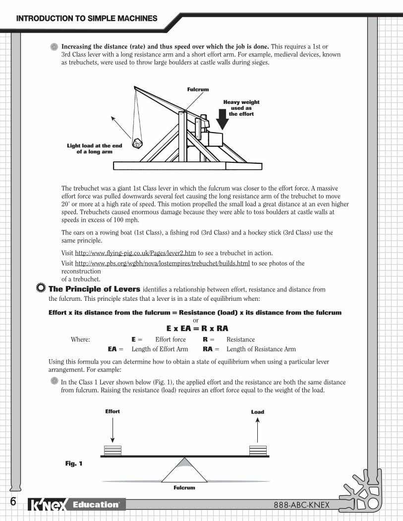
Light load at the end of a long arm
Heavy weight used as
the effort
Fulcrum
Increasing the distance (rate) and thus speed over which the job is done. This requires a 1st or 3rd Class lever with a long resistance arm and a short effort arm. For example, medieval devices, known as trebuchets, were used to throw large boulders at castle walls during sieges.
The trebuchet was a giant 1st Class lever in which the fulcrum was closer to the effort force. A massive effort force was pulled downwards several feet causing the long resistance arm of the trebuchet to move 20’ or more at a high rate of speed. This motion propelled the small load a great distance at an even higher speed. Trebuchets caused enormous damage because they were able to toss boulders at castle walls at speeds in excess of 100 mph.
The oars on a rowing boat (1st Class), a fishing rod (3rd Class) and a hockey stick (3rd Class) use the same principle.
Visit http://www.flying-pig.co.uk/Pages/lever2.htm to see a trebuchet in action.
Visit http://www.pbs.org/wgbh/nova/lostempires/trebuchet/builds.html to see photos of the reconstruction of a trebuchet.
The Principle of Levers identifies a relationship between effort, resistance and distance from the fulcrum. This principle states that a lever is in a state of equilibrium when:
Effort x its distance from the fulcrum = Resistance (load) x its distance from the fulcrum or
E x EA = R x RAWhere: E = Effort force R = Resistance EA = Length of Effort Arm RA = Length of Resistance Arm
Using this formula you can determine how to obtain a state of equilibrium when using a particular lever arrangement. For example:
In the Class 1 Lever shown below (Fig. 1), the applied effort and the resistance are both the same distance from fulcrum. Raising the resistance (load) requires an effort force equal to the weight of the load.
Effort
Fig. 1
Load
Fulcrum
INTRODUCTION�TO�SIMPLE�MACHINES
888-ABC-KNEXEducation®
7
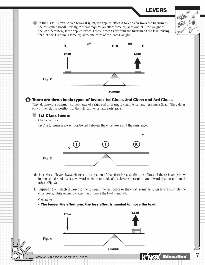
In the Class 1 Lever shown below (Fig. 2), the applied effort is twice as far from the fulcrum as the resistance (load). Raising the load requires an effort force equal to one-half the weight of the load. Similarly, if the applied effort is three times as far from the fulcrum as the load, raising that load will require a force equal to one-third of the load’s weight.
Effort Load
Fulcrum
Fig. 2
2M 1M
Fig. 3
RE F
Fig. 4
There are three basic types of levers: 1st Class, 2nd Class and 3rd Class.They all share the common components of a rigid rod or beam, fulcrum, effort and resistance (load). They differ only in the relative positions of the fulcrum, effort and resistance.
1st Class levers Characteristics:
(a) The fulcrum is always positioned between the effort force and the resistance.
(b) This class of lever always changes the direction of the effort force, so that the effort and the resistance move in opposite directions: a downward push on one side of the lever can result in an upward push or pull on the other. (Fig. 3)
(c) Depending on which is closer to the fulcrum, the resistance or the effort, some 1st Class levers multiply the effort force, while others increase the distance the load is moved.
Generally:• Thelongertheeffortarm,thelesseffortisneededtomovetheload.
Effort Load
Fulcrum
LEVERS�
www.knexeducat ion.com Education®
8
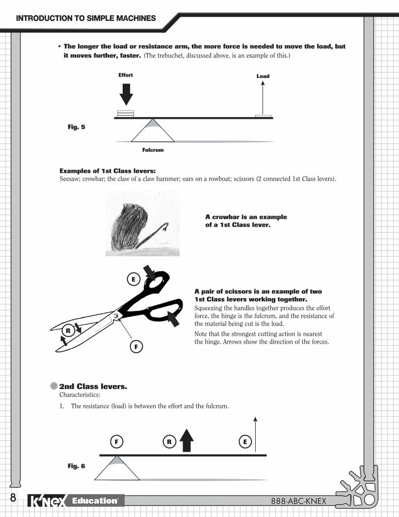
• Thelongertheloadorresistancearm,themoreforceisneededtomovetheload,but it moves further, faster. (The trebuchet, discussed above, is an example of this.)
Fig. 5
Effort Load
Fulcrum
Examples of 1st Class levers:Seesaw; crowbar; the claw of a claw hammer; oars on a rowboat; scissors (2 connected 1st Class levers).
A pair of scissors is an example of two 1st Class levers working together.Squeezing the handles together produces the effort force, the hinge is the fulcrum, and the resistance of the material being cut is the load.
Note that the strongest cutting action is nearest the hinge. Arrows show the direction of the forces.
A crowbar is an example of a 1st Class lever.
Fig. 6
R EF
2nd Class levers.Characteristics:
1. The resistance (load) is between the effort and the fulcrum.
R
E
F
INTRODUCTION�TO�SIMPLE�MACHINES
888-ABC-KNEXEducation®
9
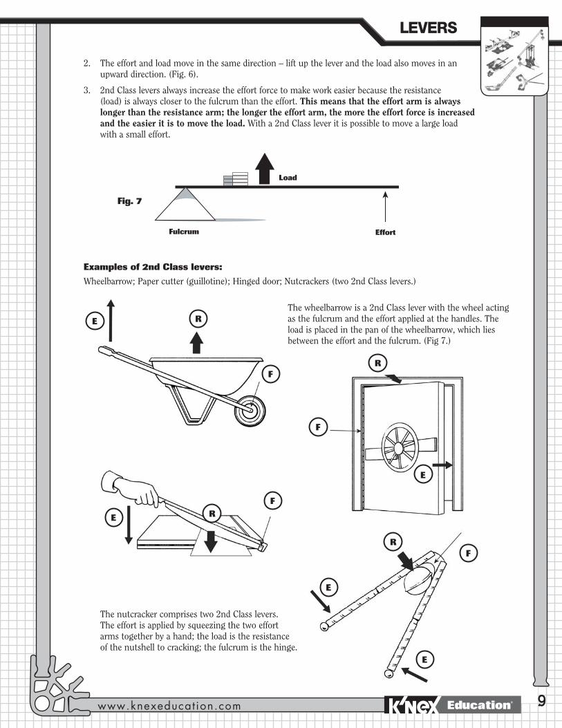
Fig. 7
Effort
Load
Fulcrum
Examples of 2nd Class levers:
Wheelbarrow; Paper cutter (guillotine); Hinged door; Nutcrackers (two 2nd Class levers.)
The wheelbarrow is a 2nd Class lever with the wheel acting as the fulcrum and the effort applied at the handles. The load is placed in the pan of the wheelbarrow, which lies between the effort and the fulcrum. (Fig 7.)
The nutcracker comprises two 2nd Class levers. The effort is applied by squeezing the two effort arms together by a hand; the load is the resistance of the nutshell to cracking; the fulcrum is the hinge.
R
R
R
R
E
E
E
E
E
F
F
F
F
2. The effort and load move in the same direction – lift up the lever and the load also moves in an upward direction. (Fig. 6).
3. 2nd Class levers always increase the effort force to make work easier because the resistance (load) is always closer to the fulcrum than the effort. This means that the effort arm is always longer than the resistance arm; the longer the effort arm, the more the effort force is increased and the easier it is to move the load. With a 2nd Class lever it is possible to move a large load with a small effort.
LEVERS�
www.knexeducat ion.com Education®
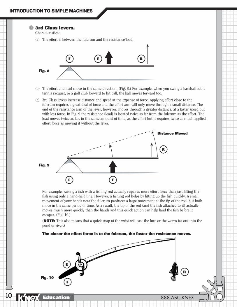
Fig. 8
REF
Fig. 9
Fig. 10
R
EF
R
E
F
10
3rd Class levers.Characteristics:
(a) The effort is between the fulcrum and the resistance/load.
(b) The effort and load move in the same direction. (Fig. 8.) For example, when you swing a baseball bat, a tennis racquet, or a golf club forward to hit ball, the ball moves forward too.
(c) 3rd Class levers increase distance and speed at the expense of force. Applying effort close to the fulcrum requires a great deal of force and the effort arm will only move through a small distance. The end of the resistance arm of the lever, however, moves through a greater distance, at a faster speed but with less force. In Fig. 9 the resistance (load) is located twice as far from the fulcrum as the effort. The load moves twice as far, in the same amount of time, as the effort but it requires twice as much applied effort force as moving it without the lever.
For example, raising a fish with a fishing rod actually requires more effort force than just lifting the fish using only a hand-held line. However, a fishing rod helps by lifting up the fish quickly. A small movement of your hands near the fulcrum produces a large movement at the tip of the rod, but both move in the same period of time. As a result, the tip of the rod (and the fish attached to it) actually moves much more quickly than the hands and this quick action can help land the fish before it escapes. (Fig. 10.)
(NOTE: This also means that a quick snap of the wrist will cast the lure or the worm far out into the pond or river.)
The closer the effort force is to the fulcrum, the faster the resistance moves.
Distance Moved
INTRODUCTION�TO�SIMPLE�MACHINES
888-ABC-KNEXEducation®
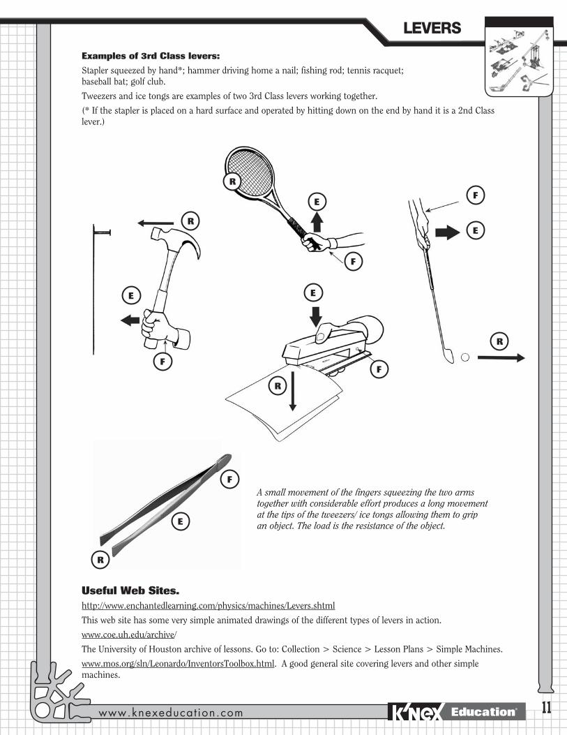
Examples of 3rd Class levers:
Stapler squeezed by hand*; hammer driving home a nail; fishing rod; tennis racquet; baseball bat; golf club.
Tweezers and ice tongs are examples of two 3rd Class levers working together.
(* If the stapler is placed on a hard surface and operated by hitting down on the end by hand it is a 2nd Class lever.)
Useful Web Sites.http://www.enchantedlearning.com/physics/machines/Levers.shtml
This web site has some very simple animated drawings of the different types of levers in action.
www.coe.uh.edu/archive/
The University of Houston archive of lessons. Go to: Collection > Science > Lesson Plans > Simple Machines.
www.mos.org/sln/Leonardo/InventorsToolbox.html. A good general site covering levers and other simple machines.
11
A small movement of the fingers squeezing the two arms together with considerable effort produces a long movement at the tips of the tweezers/ ice tongs allowing them to grip an object. The load is the resistance of the object.
R
E
F
R
F
E
R
F
E
R
F
E
R
F
E
LEVERS�
www.knexeducat ion.com Education®

12
The Seesaw: An example of a 1st Class lever.
The Seesaw
13
PROCEDUREIntroduction
If this is their first introduction to simple machines you may want to demonstrate the concept of work by having 3 or 4 students pushing as hard as they can against a wall in the classroom for 1 minute. Then ask another group of 3 or 4 students to each push a book across his or her desktop. Ask the rest of the class to decide who was doing ‘work.’
Following this, provide the students with background information on the concepts of work, force, effort, resistance, and load (See Key Terms and Key Concepts on Page 3 of this Guide.) Ask them to then identify where the effort force came from and what represented the load or resistance for both activities.
Ask them if the wall or the books moved. Explain that although the group pushing against the wall exerted a great deal of energy or force, the wall itself didn’t move and from a scientific point of view, no work was done. The group pushing the books, however, applied their effort over a distance – the books moved across the desks – and so work was done. Students should record their observations in their journals.
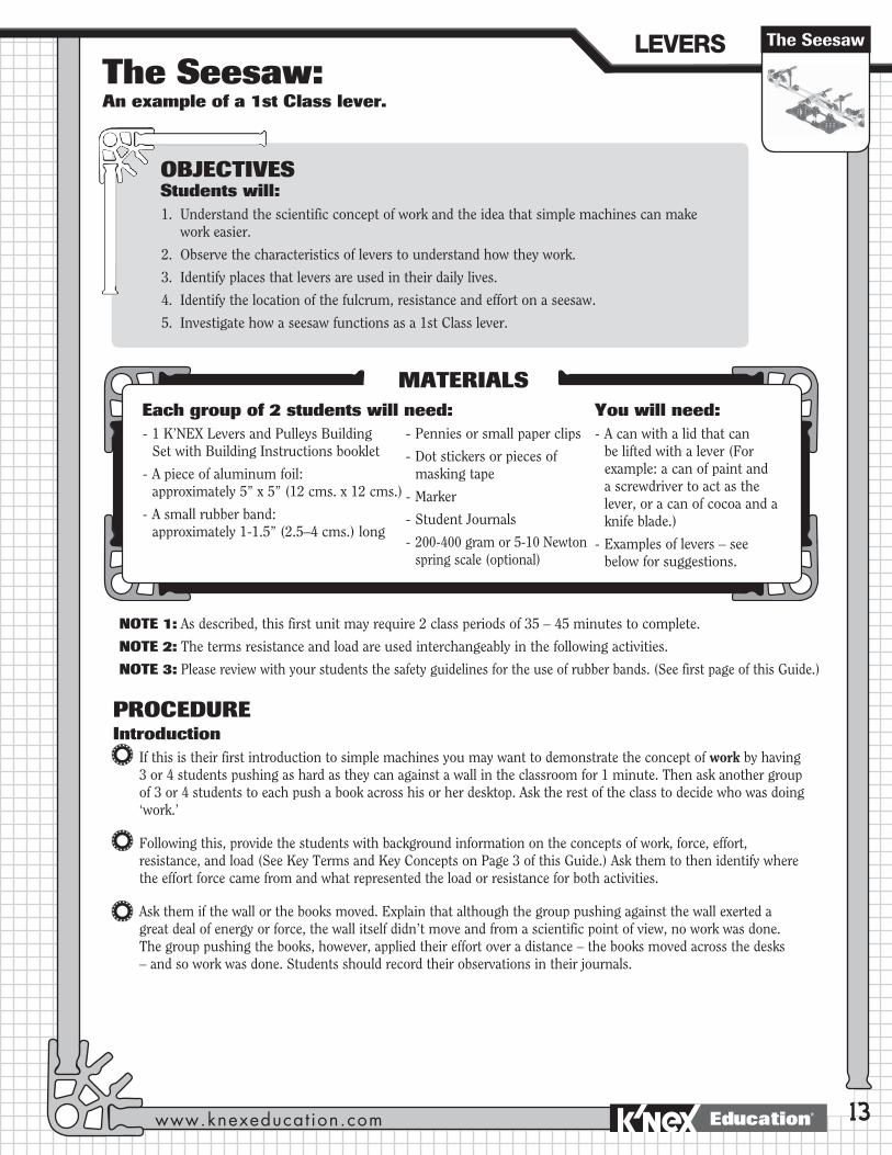
OBJECTIVESStudents will:1. Understand the scientific concept of work and the idea that simple machines can make
work easier.
2. Observe the characteristics of levers to understand how they work.
3. Identify places that levers are used in their daily lives.
4. Identify the location of the fulcrum, resistance and effort on a seesaw.
5. Investigate how a seesaw functions as a 1st Class lever.
MATERIALSEach group of 2 students will need: - 1 K’NEX Levers and Pulleys Building
Set with Building Instructions booklet
- A piece of aluminum foil: approximately 5” x 5” (12 cms. x 12 cms.)
- A small rubber band: approximately 1-1.5” (2.5–4 cms.) long
- Pennies or small paper clips
- Dot stickers or pieces of masking tape
- Marker
- Student Journals
- 200-400 gram or 5-10 Newton spring scale (optional)
You will need:- A can with a lid that can
be lifted with a lever (For example: a can of paint and a screwdriver to act as the lever, or a can of cocoa and a knife blade.)
- Examples of levers – see below for suggestions.
NOTE 1: As described, this first unit may require 2 class periods of 35 – 45 minutes to complete.
NOTE 2: The terms resistance and load are used interchangeably in the following activities.
NOTE 3: Please review with your students the safety guidelines for the use of rubber bands. (See first page of this Guide.)
LEVERS�
www.knexeducat ion.com Education®
14
Explain to the students that they will be investigating an example of a simple machine – the lever – to understand how it can help make work easier. Provide a definition of a simple machine if the students have not previously been introduced to the concept. (See Page 2 of the Guide.)
Discuss how levers are probably one of the oldest machines known – they were perhaps used in prehistoric times by people wanting to move large boulders or even to get mammoths out of pit traps. Explain that if we know what to look for we will find levers being used everywhere. We even have levers in our bodies – our arms and legs function as levers.
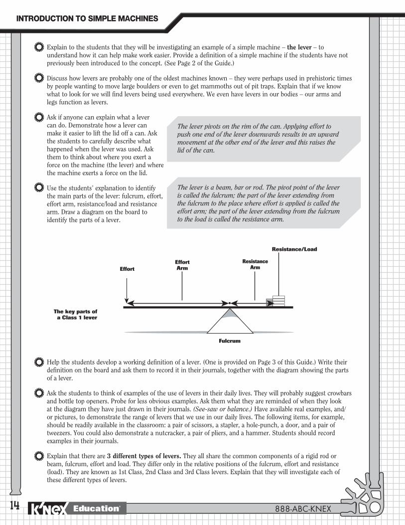
Ask if anyone can explain what a lever can do. Demonstrate how a lever can make it easier to lift the lid off a can. Ask the students to carefully describe what happened when the lever was used. Ask them to think about where you exert a force on the machine (the lever) and where the machine exerts a force on the lid.
Use the students’ explanation to identify the main parts of the lever: fulcrum, effort, effort arm, resistance/load and resistance arm. Draw a diagram on the board to identify the parts of a lever.
Help the students develop a working definition of a lever. (One is provided on Page 3 of this Guide.) Write their definition on the board and ask them to record it in their journals, together with the diagram showing the parts of a lever.
Ask the students to think of examples of the use of levers in their daily lives. They will probably suggest crowbars and bottle top openers. Probe for less obvious examples. Ask them what they are reminded of when they look at the diagram they have just drawn in their journals. (See-saw or balance.) Have available real examples, and/or pictures, to demonstrate the range of levers that we use in our daily lives. The following items, for example, should be readily available in the classroom: a pair of scissors, a stapler, a hole-punch, a door, and a pair of tweezers. You could also demonstrate a nutcracker, a pair of pliers, and a hammer. Students should record examples in their journals.
Explain that there are 3 different types of levers. They all share the common components of a rigid rod or beam, fulcrum, effort and load. They differ only in the relative positions of the fulcrum, effort and resistance (load). They are known as 1st Class, 2nd Class and 3rd Class levers. Explain that they will investigate each of these different types of levers.
The lever pivots on the rim of the can. Applying effort to push one end of the lever downwards results in an upward movement at the other end of the lever and this raises the lid of the can.
The lever is a beam, bar or rod. The pivot point of the lever is called the fulcrum; the part of the lever extending from the fulcrum to the place where effort is applied is called the effort arm; the part of the lever extending from the fulcrum to the load is called the resistance arm.
EffortEffort Arm
Resistance Arm
Fulcrum
Resistance/Load
The key parts of a Class 1 lever
INTRODUCTION�TO�SIMPLE�MACHINES
888-ABC-KNEXEducation®

15
Suggest that they search the Internet for additional information about levers. (Recommend that they enter the key words: Simple Machines into a search engine such as Google or visit http://www.professorbeaker.com and search for ‘lever’.)
Explain that the students will investigate the SEESAW as an example of a lever. If the school playground has a seesaw, begin your introduction to the activity by gathering the students around it, asking them to identify the component parts and then explaining how it works. It is something that they use for fun, but ask them how they think a seesaw can help make work easier.
This can be can demonstrated by taking a chair or stool outside with you and asking if there is anyone who believes that they could lift you up if you were sitting on it.
Next, ask one of the smaller students in the class to sit at one end of the seesaw and suggest that they try to lift you from the ground. You should sit on the opposite side of the seesaw at the end. Ask the students for suggestions as to how lifting you off the ground can be accomplished and then try these. If locating you closer to the fulcrum is not suggested then offer this as an option to the class. The class should realize that with the help of a simple machine – a lever – one of the smaller members of the class was able to carry out the job on his/her own. The seesaw (an example of a lever) has made the work of lifting a load easier.
The Seesaw
Class IdeaYou may find it useful to create a word wall composed of the words and terms the students may need when discussing their investigations and findings, as well as when making labeled drawings and written descriptions. Words could be written on cards with descriptors on the back.
The students should realize that it is unlikely that anyone in the class would be able to do this on his/her own.
Some levers can help to lift heavy loads with a small amount of applied effort force.
Building ActivityOrganize the class into teams of 2 students and distribute 1 K’NEX Levers and Pulleys Building Set to EACH group.
Ask them to open up the materials and locate the Building Instructions booklet. If the class has not used K’NEX building materials before, draw their attention to the building tips page, particularly the information concerning the gray connectors. It is crucial that the students grasp the building concept at this stage so that frustrations are avoided later.
Provide some basic guidelines for maintaining all the pieces in the set for future use.
Remind them that they will need about 5 minutes at the end of the class period for cleaning up the materials.
Explain that they are going to build a model of a seesaw – an example of a lever. They will then use the model to investigate (i) how a lever can help them do work and (ii) identify the class of lever to which it belongs.
Invite the students to build the SEESAW model (Pages 2-3 of the Building Instructions booklet.) We recommend that one student build Steps 1-3 and the other, Steps 4-8. The parts should then be assembled, as shown, to form the completed seesaw. (Alternatively, you can ask each pair of students to decide themselves how to build the model within a 10-minute time frame – this will give them opportunity to work cooperatively and will necessarily require a division of labor.)
LEVERS�
www.knexeducat ion.com Education®

16
Building Tips:•MakesurethestudentslookatthebackpageoftheBuildingInstructionsbooklettounderstandhowto
join the two gray connectors.
•Whenjoiningthepurpleconnectorstothewhiteconnectorandthegreenconnector(STEP5)werecommend that the short green rods be inserted into the gray connectors FIRST. It is then much easier to snap them into the white and green connectors.
•Ifyourstudents’seesawsdon’tbalancewhenconstructed,askthemtocheckthatalltherodsarefirmly in position in the connectors and that all the parts are lined up/orientated exactly as shown in the building instructions.
Inquiry Activity: How does a lever help you do work?Distribute stickers or tape to each group and ask the students to recall the 3 main components of the lever. (Fulcrum, effort, resistance/load). Ask them to write abbreviations for these on a sticker or a piece of tape. Put them to one side for later.
F - Fulcrum L - Load E - Effort
Remind the students to make notes and drawings of their observations as they work through the activities. They will use these to summarize their findings about this class of lever.
ß Provide each group with a piece of foil filled with pennies or paper clips and a rubber band. Remind the class about rubber band safety procedures. Use the following script to help the students explore the function of the lever.
Steps1. (a) Feel the load: Lay your hand flat on the desk with your palm facing up. Put the foil package in the palm of
your hand and lift it up from the desk. Take turns doing this. Explain that the foil package represents the load or resistance.
(b) Is the load heavy? Could you feel the weight of the load in your hand?
2. (a) Use the lever: Now place the load on one end of the seesaw. Secure it using a rubber band. What happens to the end of the seesaw with the load attached to it? Push down on the empty seat to lift the load.
(b) Did it feel easier, more difficult or just the same to lift the load this time?
(c) In which direction did you apply your effort (push)?
(d) In which direction did the load move?
(e) How did these directions differ from when you moved the load in your hand?
Students should consider the weight of the load in their hands. This provides an opportunity to introduce the students to the idea that weight is also a force. The effect of using a weight is the same as pushing down with a finger.
Students should notice:
•Thewayinwhichoneendoftheseesawgoesdownwhentheloadisattachedbut will not move again until they push the other end (apply an effort.)
•Liftingtheloadwasneithereasiernorharderusingtheseesaw–thefulcrumwas in the middle and you need the same amount of effort to lift the load, with or without the seesaw.
•NOTE: Some students may feel it was easier to move the load using the seesaw than without it. Discuss how they might be able to develop a fair test to check out their ideas. They could come up with different ideas for measuring the load and effort. These could include using non-statutory measurements such as the number of paper clips in the load and in the effort needed to raise it, or using force meters. [See: Extending the Idea.]
•Theypusheddown on the end of the seesaw and the load moved up. From this they can conclude that the seesaw changed the direction of the effort force.
INTRODUCTION�TO�SIMPLE�MACHINES
888-ABC-KNEXEducation®

17
3. Ask the students to take their labels and place them in the appropriate locations on their model to identify the fulcrum, resistance and effort. Add two more labels with arrows to show in which direction the effort moves and in which direction the load moves.
4. Making lifting easier: Ask the students to rebuild the seesaw so that the fulcrum is closer to one of the ends. Draw a sketch on the board to demonstrate the new arrangement.
5. Ask the students to predict, giving reasons, if this modification to the seesaw will make any difference to the effort they need to apply to raise the load. Ask them to test their predictions – they can use the following process or they can be encouraged to develop their own test:
(a) Place the load on the seat of the short arm.
(b) Push down on the empty seat to lift the load.
(c) What do you notice?
(d) Compared to when the fulcrum was in the middle, is it now easier or harder to lift the load?
(e) What do you notice about the distance that the effort end moves in comparison to the load end?
6. (a) Place the load on the seat of the long arm.
(b) Push down on the empty seat to lift the load.
(c) What do you notice?
(d) Compared to when the fulcrum was in the middle, is it now easier or harder to lift the load?
(e) Compared to when the load was on the short arm, is it now easier or harder to lift it?
The use of the directional arrows may help the students visualize what is happening in their model when they record their observations and make labeled diagrams.
Students should notice that it is easier to lift the load when it is closer to the fulcrum. They should notice that the effort arm moves further than the resistance arm but very little effort needs to be applied to lift the load at the end of the resistance arm.
Students should notice that it is harder to lift the load when it sits on the side furthest from the fulcrum. This demonstratesanotherfunctionoflevers–theycanbeusedto increase [multiply] or decrease movements depending on which end of the lever is used as the effort.
They can either work out for themselves how to make this modification to the design or they can be told to replace the yellow rods on one side of the seesaw with (i) blue rods and/or (ii) white rods.
The Seesaw
RE F
LEVERS�
www.knexeducat ion.com Education®
18
7. Ask the students to check the Building Instructions booklet to discover to which class of lever the seesaw belongs.
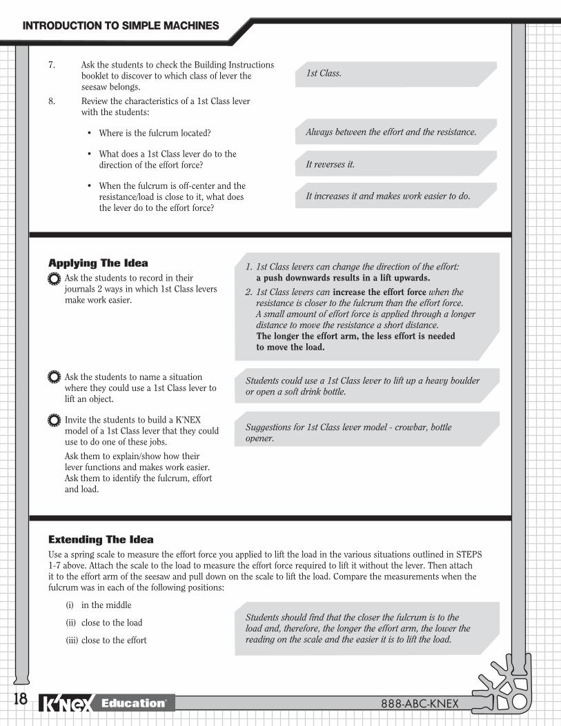
8. Review the characteristics of a 1st Class lever with the students:
• Whereisthefulcrumlocated?
• Whatdoesa1stClassleverdotothe direction of the effort force?
• Whenthefulcrumisoff-centerandtheresistance/load is close to it, what does the lever do to the effort force?
Applying The IdeaAsk the students to record in their journals 2 ways in which 1st Class levers make work easier.
Ask the students to name a situation where they could use a 1st Class lever to lift an object.
Invite the students to build a K’NEX model of a 1st Class lever that they could use to do one of these jobs.
Ask them to explain/show how their lever functions and makes work easier. Ask them to identify the fulcrum, effort and load.
1. 1st Class levers can change the direction of the effort: a push downwards results in a lift upwards.
2. 1st Class levers can increase the effort force when the resistance is closer to the fulcrum than the effort force. A small amount of effort force is applied through a longer distance to move the resistance a short distance. The longer the effort arm, the less effort is needed to move the load.
Extending The IdeaUse a spring scale to measure the effort force you applied to lift the load in the various situations outlined in STEPS 1-7 above. Attach the scale to the load to measure the effort force required to lift it without the lever. Then attach it to the effort arm of the seesaw and pull down on the scale to lift the load. Compare the measurements when the fulcrum was in each of the following positions:
(i) in the middle
(ii) close to the load
(iii) close to the effort
1st Class.
Always between the effort and the resistance.
It reverses it.
It increases it and makes work easier to do.
Suggestions for 1st Class lever model - crowbar, bottle opener.
Students could use a 1st Class lever to lift up a heavy boulder or open a soft drink bottle.
Students should find that the closer the fulcrum is to the load and, therefore, the longer the effort arm, the lower the reading on the scale and the easier it is to lift the load.
INTRODUCTION�TO�SIMPLE�MACHINES
888-ABC-KNEXEducation®
19
JOURNAL CHECK: 4 Definition and labeled diagram of a lever.
4 Examples of levers.
4 Findings from experiments.
4 Ways in which levers make work easier.
The Seesaw
NOTES:
__________________________________________________________________________________________________
__________________________________________________________________________________________________
__________________________________________________________________________________________________
__________________________________________________________________________________________________
__________________________________________________________________________________________________
__________________________________________________________________________________________________
__________________________________________________________________________________________________
__________________________________________________________________________________________________
__________________________________________________________________________________________________
__________________________________________________________________________________________________
__________________________________________________________________________________________________
__________________________________________________________________________________________________
__________________________________________________________________________________________________
__________________________________________________________________________________________________
__________________________________________________________________________________________________
__________________________________________________________________________________________________
__________________________________________________________________________________________________
__________________________________________________________________________________________________
__________________________________________________________________________________________________
__________________________________________________________________________________________________
__________________________________________________________________________________________________
LEVERS�
www.knexeducat ion.com Education®
20
The Balance: An example of a 1st Class lever.
The Balance
21
PROCEDUREIntroduction
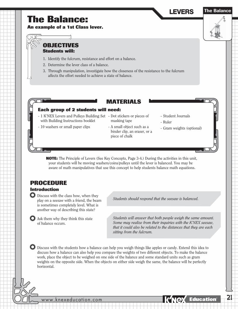
Discuss with the class how, when they play on a seesaw with a friend, the beam is sometimes completely level. What is another way of describing this state?
Ask them why they think this state of balance occurs.
Discuss with the students how a balance can help you weigh things like apples or candy. Extend this idea to discuss how a balance can also help you compare the weights of two different objects. To make the balance work, place the object to be weighed on one side of the balance and some standard units such as gram weights on the opposite side. When the objects on either side weigh the same, the balance will be perfectly horizontal.
OBJECTIVESStudents will:
1. Identify the fulcrum, resistance and effort on a balance.
2. Determine the lever class of a balance.
3. Through manipulation, investigate how the closeness of the resistance to the fulcrum affects the effort needed to achieve a state of balance.
MATERIALSEach group of 2 students will need: - 1 K’NEX Levers and Pulleys Building Set
with Building Instructions booklet
- 10 washers or small paper clips
- Dot stickers or pieces of masking tape
- A small object such as a binder clip, an eraser, or a piece of chalk
- Student Journals
- Ruler
- Gram weights (optional)
NOTE: The Principle of Levers (See Key Concepts, Page 3-4.) During the activities in this unit, your students will be moving washers/coins/pulleys until the lever is balanced. You may be aware of math manipulatives that use this concept to help students balance math equations.
Students should respond that the seesaw is balanced.
Students will answer that both people weigh the same amount. Some may realize from their inquiries with the K’NEX seesaw, that it could also be related to the distances that they are each sitting from the fulcrum.
LEVERS�
www.knexeducat ion.com Education®

22
Balances can also be used to make it easier to carry a heavy load. Students should look at the photo on Page 4 of the K’NEX Building Instructions booklet. Ask them why it might be easier to carry a load in this way.
Ask the students to draw a picture of something that is balanced or describe in their journals a situation where a balance is used.
Explain that they will build a model of a balance to continue their investigation into levers. A balance is another example of a lever and they will investigate to which class of lever it belongs. They will also observe what happens when they move the positions of the load and the effort on the lever.
Inquiry Activity: How do we balance a balance?Ask the students to use stickers or tape to identify and label the parts of the balance.
F - Fulcrum L - Load E - Effort
Ask the students to which class of lever the balance belongs and why. They should write their answer, together with a drawing of the labeled balance, in their journals.
Use the following script to help the students discover how to balance the balance.
Steps
1. (a) Remove the gray trays (gray pulley wheels) from the model. Push the red and orange hangers to the end of the balance arms. Once the two arms are stationary, observe and describe, using the correct vocabulary, what the model is doing.
(b) What happens when one end of the model is given a small push/ has a force applied? Explain your observations.
Students should be helped to understand that the large load is split into two equal parts so that the weight of the load is evenly distributed and balanced across the man’s shoulders.
The balance will not move because the forces acting on either arm are equal.
When a force is applied to one side, the balance moves because the forces acting on it are unequal. The movement of the balance arm will be in the same direction as the applied force.
Building ActivityOrganize the class into teams of 2 (maximum 3) students and distribute 1 K’NEX Levers and Pulleys Building Set to EACH group.
Invite the students to build the BALANCE model (Pages 4-5 of the Building Instructions booklet.) We recommend that one student build Steps 1-2 and the other, Steps 3-7. The parts should then be assembled, as shown, to form the completed balance.
Discuss with the students the similarities between the K’NEX Balance model and the Seesaw model investigated in the previous lesson.
INTRODUCTION�TO�SIMPLE�MACHINES
888-ABC-KNEXEducation®

23
(c) Discuss with the students how this activity demonstrates that an object will remain stationary, or at rest, until a force acts on it.
2. (a) Replace the hanging trays (gray pulleys) so that there are two (2) pulleys on one side and one (1) pulley on the other. Push both of the hanging trays (gray pulleys) to the end of the balance arms.
(b) What happens to the balance? Why does this happen?
3. Ask the students what they have to do to balance the forces in the model.
4. Ask the students to go back to their unbalanced model with 2 pulleys on one side and 1 pulley on the other. Ask them to find a different way to balance the model without adding or removing pulleys. Offer the following suggestions if necessary:
(a) Slide the hanging trays, one at a time, closer to the center.
(b) What happens?
(c) Why does this happen?
5. Distribute a table template for the students to record their results from the next set of activities (Steps 6-8.) Remind them that they should also make drawings of their models.
The Balance
Students should notice that the tray with two gray pulleys goes down while the other side goes up. This is because the two pulleys on one side are heavier than the one pulley on the other side. They should be helped to understand that this is the result of unbalanced forces in action.
Students may either add or remove a gray pulley to one or other side in order to equalize the weights on both sides. The students should be encouraged to discuss their observations in terms of balanced and unbalanced forces.
Students should notice that the balance arms become level when they move the tray with two pulleys closertothecenter while leaving the other tray at the end. This is because the load is closer to the fulcrum so it requires less effort to balance it.
Remind the students that in their previous activity with the seesaw they discovered that a small amount of effort applied a long distance from the fulcrum can lift a heavier load closer to the fulcrum.
Effort Arm Load/Resistance Arm
Number of Distance from fulcrum Object Distance from fulcrum washers/paperclips (weight)
LEVERS�
www.knexeducat ion.com Education®

24
6. (a) Change the balance so that there is one pulley on each hanging tray. Make sure each tray is the same distance from the fulcrum. Measure that distance and record it in the table.
(b) Place a small object on the load tray. Use washers or small paper clips as the weights on the other tray. Add washers or paper clips to the effort tray until the balance is level.
(c) Count how many washers/paperclips it takes to balance the balance. Record your result in the table.
7. (a) Move the load closer to the fulcrum. Balance the load by changing the amount of the effort force (weight). Record the measurements in the table.
(b) What do you notice about the length of the effort arm and the length of the resistance (load) arm?
(c) Did you add or remove weight? Why?
(d) Repeat this, moving the load and balancing it again. Record the measurements in the table.
(e) Make a drawing of the balance in your journals to show the positions of the fulcrum, effort and load and the directions in which the forces are acting.
8. (a) Move the effort closer to the fulcrum. Balance the load by changing the amount of the effort force. Record the measurements in the table.
(b) What do you notice about the length of the effort arm and the length of the resistance (load) arm?
(c) Did you add or remove weight? Why?
(d) Repeat this, moving the effort and balancing the load again. Record the measurements in the table.
(e) Make a sketch of the balance in your journals to show the positions of the fulcrum, effort and load and the directions in which the forces are acting.
Applying The IdeaDiscuss the results of the experiments with the whole class. Their investigation involved balancing the forces acting on the model and demonstrated that when balanced, the forces on one side must equal the forces on the opposite side.
Ask the students to record in their journals the processes they used to balance the system. They should understand that two factors are involved in balancing the lever:
1. The weight (force) of the load and the effort.
2. The distances of the effort and the load from the fulcrum.
Challenge the students to establish a general rule for balancing a lever and write it in their journals. They should understand from their inquiries that the closer the load is to the fulcrum the less effort is needed to move it. Encourage them to include a reference to the lengths of the effort arm and resistance arm. (See 7b and 8b above.)
Students can put the blue rod through the washers or paper clips so that they do not fall off the tray.
Students will need to removeweight to balance the load since it requires lesseffort when the load is close to the fulcrum and the effort arm is longer than the resistance arm.
Students will need to addweight to balance the load since it requires moreeffortforce when it is applied close to the fulcrum and the effort arm is shorter than the resistance arm.
INTRODUCTION�TO�SIMPLE�MACHINES
888-ABC-KNEXEducation®

25
The Balance
JOURNAL CHECK: 4 Explanation of how to balance the balance.
4 Labeled diagram of the balance identifying fulcrum, effort, load and the directions in which the forces are acting.
4 Completed table with results of their balance experiments.
4 General rule for balancing a lever.
NOTE: You may want to present the activity on a pair of scissors next (see Page 35.) A pair of scissors serves as an example of two connected 1st Class levers.
Extending The Idea
1. Use gram weights and a ruler to determine the mathematical relationship involved in balancing the lever. Balance the lever with gram weights on both hanging trays. Use the ruler to measure the distances of the load and the effort from the fulcrum when the lever is balanced.
The Principle of Levers states that for a lever to be balanced:
Effort x its distance from the fulcrum = Resistance (load) x its distance from the fulcrum or
E x EA = R x RA
Where: E = Effort force R = Resistance EA = Length of Effort Arm RA = Length of Resistance Arm
NOTE: In order to simplify the activity, ignore the units.
2. Students could be set the task of applying the Principle of Levers to find the weight of an unknown object using only one 10g weight.
NOTES:
__________________________________________________________________________________________________
__________________________________________________________________________________________________
__________________________________________________________________________________________________
__________________________________________________________________________________________________
__________________________________________________________________________________________________
__________________________________________________________________________________________________
__________________________________________________________________________________________________
__________________________________________________________________________________________________
LEVERS�
www.knexeducat ion.com Education®

26
The Wheelbarrow: An example of a 2nd Class lever.
The Wheelbarrow
27
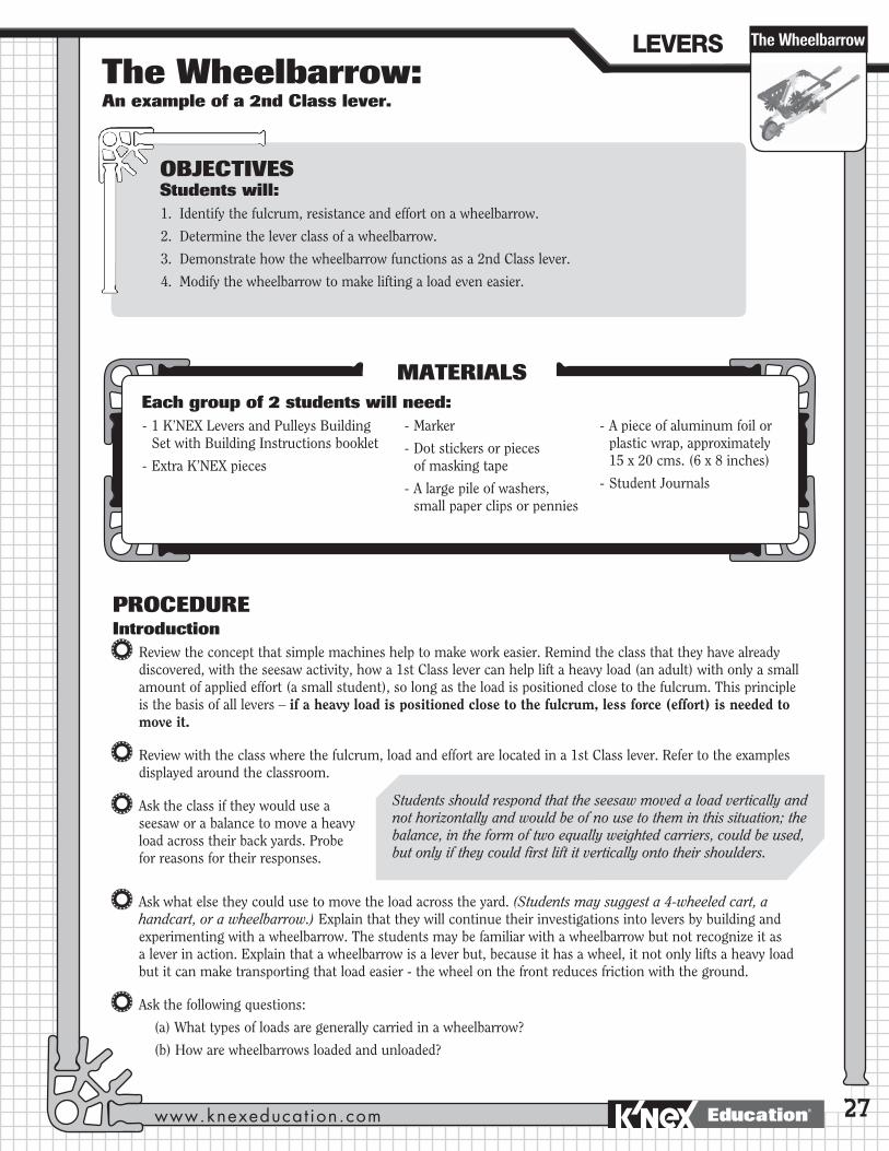
PROCEDUREIntroduction
Review the concept that simple machines help to make work easier. Remind the class that they have already discovered, with the seesaw activity, how a 1st Class lever can help lift a heavy load (an adult) with only a small amount of applied effort (a small student), so long as the load is positioned close to the fulcrum. This principle is the basis of all levers – if a heavy load is positioned close to the fulcrum, less force (effort) is needed to move it.
Review with the class where the fulcrum, load and effort are located in a 1st Class lever. Refer to the examples displayed around the classroom.
Ask the class if they would use a seesaw or a balance to move a heavy load across their back yards. Probe for reasons for their responses.
Ask what else they could use to move the load across the yard. (Students may suggest a 4-wheeled cart, a handcart, or a wheelbarrow.) Explain that they will continue their investigations into levers by building and experimenting with a wheelbarrow. The students may be familiar with a wheelbarrow but not recognize it as a lever in action. Explain that a wheelbarrow is a lever but, because it has a wheel, it not only lifts a heavy load but it can make transporting that load easier - the wheel on the front reduces friction with the ground.
Ask the following questions:
(a) What types of loads are generally carried in a wheelbarrow?
(b) How are wheelbarrows loaded and unloaded?
OBJECTIVESStudents will:1. Identify the fulcrum, resistance and effort on a wheelbarrow.
2. Determine the lever class of a wheelbarrow.
3. Demonstrate how the wheelbarrow functions as a 2nd Class lever.
4. Modify the wheelbarrow to make lifting a load even easier.
MATERIALSEach group of 2 students will need: - 1 K’NEX Levers and Pulleys Building
Set with Building Instructions booklet
- Extra K’NEX pieces
- Marker
- Dot stickers or pieces of masking tape
- A large pile of washers, small paper clips or pennies
- A piece of aluminum foil or plastic wrap, approximately 15 x 20 cms. (6 x 8 inches)
- Student Journals
Students should respond that the seesaw moved a load vertically and not horizontally and would be of no use to them in this situation; the balance, in the form of two equally weighted carriers, could be used, but only if they could first lift it vertically onto their shoulders.
LEVERS�
www.knexeducat ion.com Education®
28
Building ActivityOrganize the class into teams of 2 (maximum 3) students and distribute 1 K’NEX Levers and Pulleys Building Set to EACH group.
Invite the students to build the WHEELBARROW model (Pages 6-7 of the Building Instructions booklet.) We recommend that one student build Steps 1-2 and the other, Steps 3-4. The parts should then be assembled, as shown, to form the completed wheelbarrow.
BUILDING TIP: Add gray spacers to the axle, one on either side of the wheel. This will provide greater stability as the wheelbarrow carries its load.
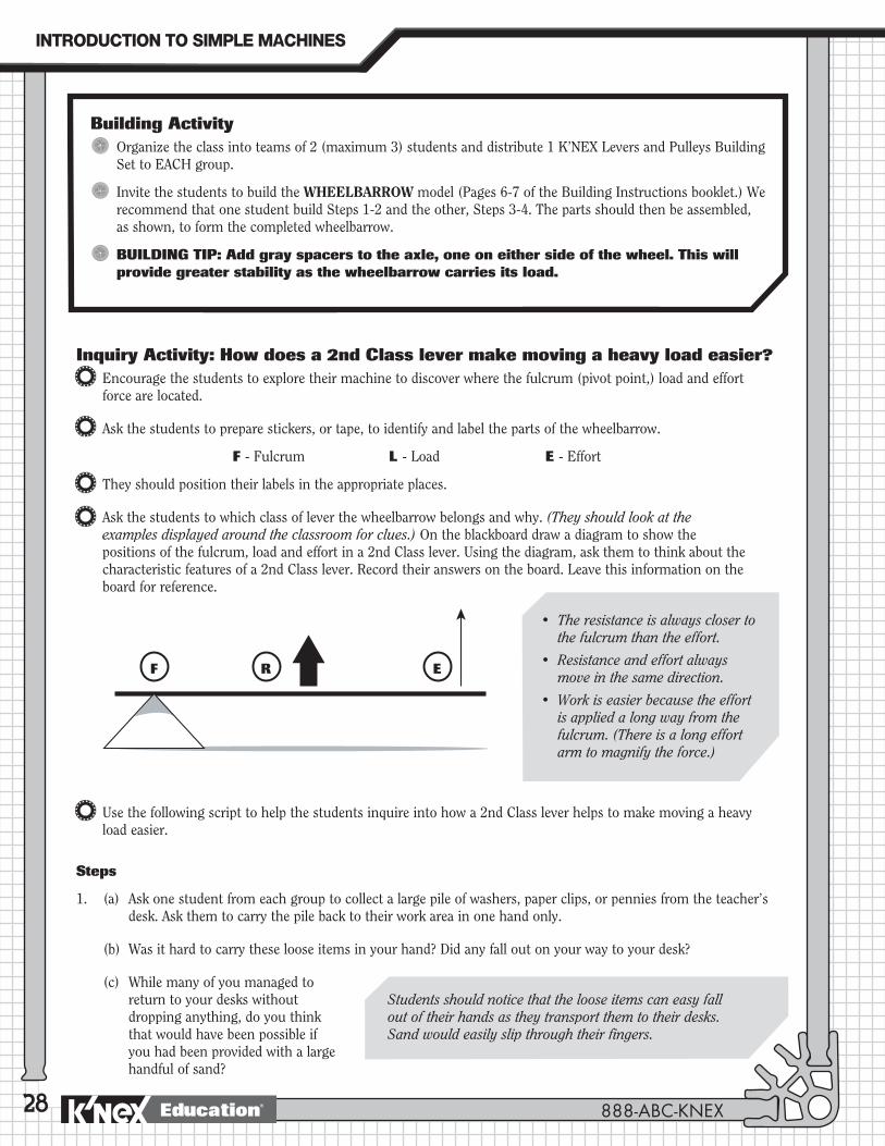
R EF
• Theresistanceisalwaysclosertothe fulcrum than the effort.
• Resistanceandeffortalwaysmove in the same direction.
• Workiseasierbecausetheeffortis applied a long way from the fulcrum. (There is a long effort arm to magnify the force.)
Inquiry Activity: How does a 2nd Class lever make moving a heavy load easier?Encourage the students to explore their machine to discover where the fulcrum (pivot point,) load and effort force are located.
Ask the students to prepare stickers, or tape, to identify and label the parts of the wheelbarrow.
F - Fulcrum L - Load E - Effort
They should position their labels in the appropriate places.
Ask the students to which class of lever the wheelbarrow belongs and why. (They should look at the examples displayed around the classroom for clues.) On the blackboard draw a diagram to show the positions of the fulcrum, load and effort in a 2nd Class lever. Using the diagram, ask them to think about the characteristic features of a 2nd Class lever. Record their answers on the board. Leave this information on the board for reference.
Use the following script to help the students inquire into how a 2nd Class lever helps to make moving a heavy load easier.
Steps
1. (a) Ask one student from each group to collect a large pile of washers, paper clips, or pennies from the teacher’s desk. Ask them to carry the pile back to their work area in one hand only.
(b) Was it hard to carry these loose items in your hand? Did any fall out on your way to your desk?
(c) While many of you managed to return to your desks without dropping anything, do you think that would have been possible if you had been provided with a large handful of sand?
Students should notice that the loose items can easy fall out of their hands as they transport them to their desks. Sand would easily slip through their fingers.
INTRODUCTION�TO�SIMPLE�MACHINES
888-ABC-KNEXEducation®
29
2. (a) Give each group a sheet of aluminum foil or plastic wrap.
(b) Line the tray of the K’NEX wheelbarrow with the aluminum foil or plastic wrap. Fill the tray with the pile of washers, paper clips, or pennies. Then use the wheelbarrow to lift, move, and dump the load. Make sure you dump the load over the front of the wheelbarrow, not the side.
(c) What did you notice about moving the pile of material with the wheelbarrow? What kinds of loads would be easiest to move in a wheelbarrow and why?
(d) Imagine that you have to provide someone who has never used a wheelbarrow with precise instructions for its use. In your journals record step-by-step what they need to do.
3. (a) An even heavier load needs to be moved. What changes could be made to your present design to allow it to move this heavier load without increasing the effort needed to lift the handles? Using extra K’NEX pieces, change your wheelbarrow to make it easier to lift the load. (Students may need some help with this; ask them what they know, from their inquiries so far, about making a load easier to move.)
(b) What did you do to your model to make it easier to lift the load?
(c) Why did you choose to do that?
Applying The Idea
Review with the class the characteristics of a 2nd Class lever:
(a) Where is the fulcrum located?
(b) Do the effort and resistance (load) move in opposite directions, as is the case with a 1st Class lever?
(c) What happens when the effort is applied to the lever a long way from the fulcrum?
Students should notice that it is easier to move the loose pile in the wheelbarrow because it is collected in one place and all they have to do is lift the handle to move it. The wheelbarrow can be used to move many different loads, but is particularly useful for moving loose, heavy loads like sand or bricks.
The wheelbarrow is a 2nd class lever so to make lifting easier, the students should lengthenthewheelbarrow’shandles. This will move the effort even further from the fulcrum and make it easier to lift the load.
No. Effort and resistance always move in the same direction. Liftuptheleverandtheloadalsomovesupwards.
Students should include: place objects in the wheelbarrow - apply effort to lift the handles and the supports so that the wheelbarrowpivotsonthewheel–thisliftstheloadatthesametime–applyefforttopushthewheelbarrowforward–the wheel helps overcome friction as the wheelbarrow travels over the ground - apply more effort to raise the handles higher todumpouttheload–lowerthehandlesofthewheelbarrowso the supports rest on the ground.
The Wheelbarrow
At one end of the lever, closer to the load than the effort.
It increases the force and makes work easier.
LEVERS�
www.knexeducat ion.com Education®

30
Ask the students to record in their journals the reasons why the wheelbarrow is a 2nd Class lever and how this helps make lifting heavy loads easier. They should include diagrams and sketches.
Using K’NEX, invite the students to build another example of a 2nd Class lever. Ask them to explain how the machine works and why it is a 2nd Class lever.
Suggestions for 2nd Class lever model - door, paper cutter, joystick.
Students should understand that the effort is further from the fulcrum than the load and that thelongertheeffortarm,themoretheeffortforceismultiplied. This makes it possible to move a large load with a small input of effort.
Extending The IdeaUsing the library and Internet, investigate a travois and find out how Native Americans on the Great Plains used this tool to move heavy loads. Explain that not all cultures use the wheel to help move heavy loads.
Explain how a travois is like a wheelbarrow. You may want to visit this web site for information: http://www.encyclopedia.com/html/t1/travois.asp
Likeawheelbarrow,atravoisisadeviceusedtotransportaload. It consists of a pair of long poles hitched to a horse or dog. The load is strapped across the poles. The animal pulls the load as it walks while the ends of the poles drag on the ground. The travois is like a wheelbarrow, without the wheel; it is pulled instead of pushed.
JOURNAL CHECK:
4 Identification of the wheelbarrow as a 2nd Class lever.
4 Characteristics of a 2nd Class lever, with diagrams.
4 Reasons why a 2nd Class lever makes work easier.
INTRODUCTION�TO�SIMPLE�MACHINES
888-ABC-KNEXEducation®

The Hockey Stick: An example of a 3rd Class lever.
Hockey Stick
31
PROCEDUREIntroduction
Explain to the students that they have one more Class of lever to investigate: A 3rd Class lever. Ask the students to recall the ways in which the other two classes of levers help to make work easier – changing the direction of a force and increasing a force.
Explain that to move an object using a 3rd Class lever actually requires more effort than if you were to simply move it without the lever. Ask why we might want to use this kind of lever if it requires a large input of effort.
Probe for ideas about other things that a lever might be able to do. Help the students discover that we can use levers to not only make moving/lifting objects easier but to move them further, faster with the same amount of applied effort force.
Ask the class for situations where they might want to move something very quickly over a long distance and where they would be prepared to exert a great deal of effort for a short time to accomplish this goal. (If necessary, provide a hint about sports activities.)
Explain that a number of pieces of equipment that they use or have seen used at sporting events are 3rd Class levers. People use them because they are prepared to use a lot of effort for a short time to make the ball or puck move far and fast. Ask for some examples of such equipment.
Have a display of sports equipment available – either the actual items or pictures of them. (Suggestions: ice hockey stick, baseball bat, tennis racquet, golf club, lacrosse stick, field hockey stick.) Encourage the students to create a collage with pictures of 3rd Class levers used as sports equipment.
Explain that the students will build a hockey stick to investigate the characteristics of a 3rd Class lever.
OBJECTIVESStudents will:1. Identify the fulcrum, resistance, and effort on a hockey stick
2. Determine the lever class of a hockey stick.
3. Demonstrate how the hockey stick functions as a 3rd Class lever.
4. Through measurements, demonstrate how a 3rd Class lever can increase distance and speed at the expense of force.
MATERIALSEach group of 2 students will need: - 1 K’NEX Levers and Pulleys
Building Set with Building Instructions booklet
- Marker
- Measuring tape
- Dot stickers or pieces of masking tape
- Small Post-It notes
- Student Journals
You will need:- Examples of sports equipment
such as: ice hockey stick, baseball bat, golf club, tennis racquet, field hockey stick, and lacrosse stick. (Check with your Physical Education Department.)
LEVERS�
www.knexeducat ion.com Education®

32
Inquiry Activity: How does a 3rd Class lever help to move a load faster and further?
The students should explore their machine to discover where the fulcrum (pivot point,) load, and effort force are located. Ask the students to look at the photo on Page 8 of the Building Instructions booklet and observe the position of the hockey player’s hands. Then use the model stick to hit small balls of paper. (They should take turns doing this.) Remind the students to check that their hands are positioned in the same locations on their stick as those of the player in the photo.
Ask:
(a) Which hand acts as the fulcrum? (Top hand)
(b) Which hand provides the effort? (Bottom hand)
(c) Where is the load? (The puck)
Ask the students to prepare stickers or tape to identify and label the parts of the hockey stick.
F - Fulcrum L - Load E - Effort
Discuss where the stickers should be positioned. Draw a diagram on the blackboard and ask the students to include a sketch of the labeled hockey stick in their journals. The students should also add a sentence to explain how a 3rd Class lever is different from a 2nd Class lever.
Steps
1. (a) Taketurnstodothis. Use only one hand for this experiment. Hold your hockey stick with the top of the stick in your hand and your fingers on the top purple connector. Lay your arm on your desk so the inside of your arm lines up with the edge of the desk.
Note: It may be difficult for students to realize that their wrist is the fulcrum: their wrist provides the pointofrotation–justlikeadoorhinge.
The effort is closer to the fulcrum than is the resistance/load.
Building ActivityOrganize the class into teams of 2 (maximum 3) students and distribute 1 K’NEX Levers and Pulleys Building Set to EACH group.
Invite the students to build the HOCKEY STICK model (Page 8 of the Building Instructions booklet.)
INTRODUCTION�TO�SIMPLE�MACHINES
888-ABC-KNEXEducation®

33
(b) Without moving your arm, bend your wrist away from the desk so that the hockey stick also moves away from the edge of the desk. Pay attention to the distance your wrist and the hockey stick move.
(c) What do you notice?
2. Distribute measuring tapes and ask the students to repeat the experiment in Step 1 using the following process:
(a) Hold your hand at the end of the stick with your fingers on the top purple connector. Your fingers are acting as the effort force. Repeat Step 1(b) but this time your partner should measure the distance from the edge of the desk to where you are holding the top purple connector in your hand. Then the distance from the edge of the desk to the yellow connector on the hockey stick should be measured.
(b) What do you notice? Record your measurements.
3. Using both hands, try hitting the ball of paper again with the stick. What do you notice about the distance it travels and speed it moves?
Hockey Stick
Students should notice that for a small movement of their wrist, the hockey stick quickly moves through a long distance.
NOTE: Some students may find it difficult to understand why the end of the hockey stick moves further and faster than the wrist - they will think that because they are connected they must move at the same speed.
You may want to demonstrate the different sspeed of movement in the following way. Ask two students to hold onto either end of a long hockey stick or broom handle. They should both face in the same direction. Student A represents the wrist and Student B represents the end of the hockey stick. Ask them to turn through a quarter (1/4) of a circle. The other students should note their starting point. As they turn the student who represents the end of the hockey stick will have to move quickly in order to keep up with the student representing the wrist of the hockey player. That student (B) will also have moved further than the student who is the “wrist”.
Distances moved
Student A = Wrist
Student B = End of Hockey Stick
Students should notice a significant difference between the two measurements. Depending on the flexibility of their wrists, the distance the end of the hockey stick moved could be four times greater than the distance their wrists moved.
Students should notice that it moves both further and faster than their hands.
Make sure the students retrieve the balls of paper at, or before, clean up time.
LEVERS�
www.knexeducat ion.com Education®
34
JOURNAL CHECK:
4 Identification of a hockey stick as a 3rd Class lever.
4 Labeled diagram of a hockey stick.
4 Measurements and explanation about how a hockey stick helps the players in a hockey game.
Extending The Idea
1. Using the library and Internet, investigate some of the 3rd Class levers used in sports such as baseball/softball bats, tennis racquets, golf clubs, fishing rods. How do the designs of different types of sporting equipment meet the needs of the players? What do the players need to do to meet the objectives of the game? The following web site, for example, has information on baseball bats: http://exn.ca/stories/2000/10/13/55.asp
2. Students should build a K’NEX model of one of the pieces of sports equipment they have researched. They should explain/show how the lever works and helps to complete the task. The fulcrum, effort and load should be identified.
3. If possible, show video clips of athletes using these types of equipment so that students may observe the 3rd Class levers in action.
Applying The IdeaAsk the students to write in their journals what their measurements suggest about how a hockey stick helps the players in a hockey game.
Explain that the ice hockey player in the photograph on Page 8 of the K’NEX Building Instructions booklet needs an improved design for his stick to help him score more goals. He knows that he isn’t hitting the puck fast enough but he doesn’t know whether he should buy a longer or shorter stick. Your task is to provide evidence, by modifying and testing your hockey stick, which may help him make a decision. Report your findings to the class.
The students should extend the length of the stick. A stationary puck needs a great amount of force applied to move it from a stationary position to high speed in a short time period. A longer stick makes the head of the stickmovemuchfasterthantheplayer’shands–theoptionalexperimenton Page 33 using a broom handle or hockey stick rotated through 90 degrees demonstrates this. A disadvantage of the longer stick is that with the load (puck) further from the fulcrum it requires more effort to hit it, and it may also be more difficult to control the head movement.
A shorter stick needs less effort to move the load because it is closer to the fulcrum, provides greater control over the head movement but the hitting head and, therefore, the puck won’t move as quickly.
NOTE: You could also demonstrate this concept by having 1 student use a broom with a long handle and another using a broom with a short handle to sweep over an area.
They should explain that the stick moves much further and faster than their hands. This helps them move the puck quickly across the ice, although because of the position of the effort close to the fulcrum, they must apply a large amount of effort to move even a small load.
INTRODUCTION�TO�SIMPLE�MACHINES
888-ABC-KNEXEducation®
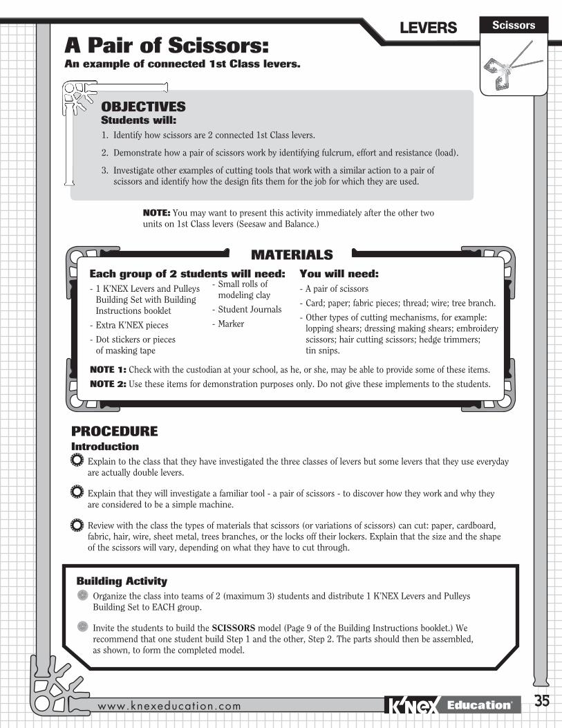
A Pair of Scissors: An example of connected 1st Class levers.
Scissors
35
PROCEDUREIntroduction
Explain to the class that they have investigated the three classes of levers but some levers that they use everyday are actually double levers.
Explain that they will investigate a familiar tool - a pair of scissors - to discover how they work and why they are considered to be a simple machine.
Review with the class the types of materials that scissors (or variations of scissors) can cut: paper, cardboard, fabric, hair, wire, sheet metal, trees branches, or the locks off their lockers. Explain that the size and the shape of the scissors will vary, depending on what they have to cut through.
OBJECTIVESStudents will:1. Identify how scissors are 2 connected 1st Class levers.
2. Demonstrate how a pair of scissors work by identifying fulcrum, effort and resistance (load).
3. Investigate other examples of cutting tools that work with a similar action to a pair of scissors and identify how the design fits them for the job for which they are used.
MATERIALSEach group of 2 students will need: - 1 K’NEX Levers and Pulleys
Building Set with Building Instructions booklet
- Extra K’NEX pieces
- Dot stickers or pieces of masking tape
- Small rolls of modeling clay
- Student Journals
- Marker
NOTE: You may want to present this activity immediately after the other two units on 1st Class levers (Seesaw and Balance.)
NOTE 1: Check with the custodian at your school, as he, or she, may be able to provide some of these items.
NOTE 2: Use these items for demonstration purposes only. Do not give these implements to the students.
You will need:- A pair of scissors
- Card; paper; fabric pieces; thread; wire; tree branch.
- Other types of cutting mechanisms, for example: lopping shears; dressing making shears; embroidery scissors; hair cutting scissors; hedge trimmers; tin snips.
Building ActivityOrganize the class into teams of 2 (maximum 3) students and distribute 1 K’NEX Levers and Pulleys Building Set to EACH group.
Invite the students to build the SCISSORS model (Page 9 of the Building Instructions booklet.) We recommend that one student build Step 1 and the other, Step 2. The parts should then be assembled, as shown, to form the completed model.
LEVERS�
www.knexeducat ion.com Education®
36
Demonstrate this to the class with either your own model or an actual pair of scissors.
Yes. The scissors have a hinge or fulcrum about which each blade rotates.
The resistance of the paper or card to the cutting blades.
Inquiry Activity: How do scissors function as connected 1st Class levers?Steps
1. (a) Ask one member of the team to hold the model of the pair of scissors out in front of them so that the blades are in a horizontal position (parallel to the floor.) They should then hold just one of the handles and allow one half of the scissors to swing freely like a seesaw.
(b) Ask the class to name a scientific concept that is used to make the scissors work. Provide a clue: they have been examining levers, so is the lever at work in the pair of scissors?
(c) Ask them to identify where the fulcrum is located, where the effort is applied (the handles) and what acts as the load.
(d) If necessary, help the students identify the two levers at work in the pair of scissors.
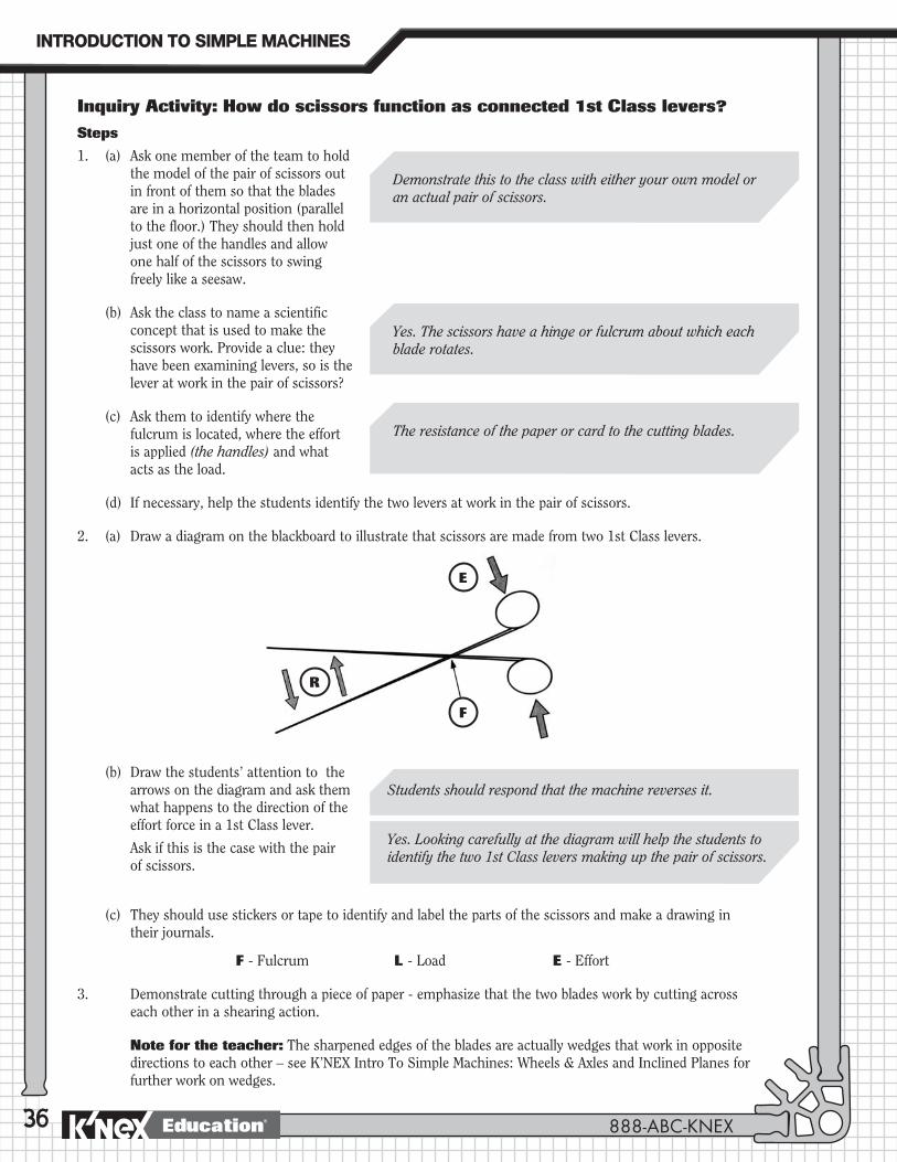
2. (a) Draw a diagram on the blackboard to illustrate that scissors are made from two 1st Class levers.
(b) Draw the students’ attention to the arrows on the diagram and ask them what happens to the direction of the effort force in a 1st Class lever.
Ask if this is the case with the pair of scissors.
(c) They should use stickers or tape to identify and label the parts of the scissors and make a drawing in their journals.
F - Fulcrum L - Load E - Effort
3. Demonstrate cutting through a piece of paper - emphasize that the two blades work by cutting across each other in a shearing action.
Note for the teacher: The sharpened edges of the blades are actually wedges that work in opposite directions to each other – see K’NEX Intro To Simple Machines: Wheels & Axles and Inclined Planes for further work on wedges.
Students should respond that the machine reverses it.
Yes.Lookingcarefullyatthediagramwillhelpthestudentstoidentify the two 1st Class levers making up the pair of scissors.
R
E
F
INTRODUCTION�TO�SIMPLE�MACHINES
888-ABC-KNEXEducation®
37
Use the following script to direct the students’ inquiry into how scissors work and why they are an example of two connected levers.
4. (a) Put a piece of modeling clay (approximately 10 cms. x 3 cms.) lengthwise between the blades of your scissors and squeeze as if you were cutting through paper.
(b) What do you notice about the depth of the indentation made by the blades?
•Wherewastheindentationdeepest?
•Whatdoesthistellyouaboutthe cutting action of the scissors?
(c) When would you want to cut near the fulcrum? When would you want to cut near the blade tips?
(d) Record your findings in your journal.
5. Using what you know about 1st Class levers, why is there a difference in cutting power along the blades of the scissors?
6. (a) Show the students a selection of other cutting tools that have a similar cutting action to scissors. (Examples: lopping shears; dressing making shears; embroidery scissors; hair cutting scissors; hedge trimmers; tin snips.)
(b) Discuss how all the cutting tools are based on the same basic design, but that the design has been modified to meet a particular need.
(c) Ask the following questions about each example:
•Whatatypeofmaterialisthisdesigned to cut?
•Wouldscissorsbeabletocutthese materials? If not, why not?
•Howdoesthedesignofthedifferent cutting tools allow them to cut materials that scissors cannot?
Students should notice that the indentation in the clay is deepest closest to the fulcrum. From this observation they should understand that the cutting power of the scissors is greatest nearest the fulcrum and decreases as you move further away.
The students should state that when the resistance is close to the fulcrum less effort force is needed to move it, while further away you need to apply more effort to move the same load. Cutting near the fulcrum is easier than cutting near the blade tips. If required, draw a diagram on the board to reinforce the concept.
They should understand that they would want to cut near the fulcrum when cutting something thick and cut near the tips when making smaller cuts or cutting thin materials.
Where possible, attempt to cut the materials the students suggest with the tool under discussion. This will demonstrate its effectiveness, or otherwise.
Students should see that cutting tools with short blades and long handles are used to cut materials like wire or thick branches–thesearedifficultthingstocutthroughandrequirea great amount of effort. The handles are long to increase the squeezing force (effort) while the short blades mean that the load is near the fulcrum (hinge,) where the cutting forces are greatest. By comparison, scissors for hair cutting tend to have long blades and short handles because the main need to is to makelongstraightcuts–onlyasmallcuttingforceisneededto cut through hair.
ScissorsLEVERS�
www.knexeducat ion.com Education®
38
Applying The IdeaExplain in your journals (i) why scissors are considered to be connected (or double) levers and (ii) how they work. Include a labeled drawing to illustrate your explanation.
Make labeled drawings of different cutting tools indicating the position of the fulcrum, effort and load. Add notes to describe how the design of the cutting tools fit them for the jobs for which they are used.
Modify your K’NEX scissors model design so that it has a much stronger cutting or gripping action. Test the revised model on the modeling clay. Make labeled drawings of the new design and write a description of how the design works and how the modifications have made the cutting action stronger.
Extending The IdeaInvestigate other connected levers and build them using K’NEX. Explain how double levers help do work based on their class. For example, a nutcracker is a 2nd Class connected lever. A large amount of force is required to break the nut’s hard shell. So much so, it’s almost impossible to do it by hand. It is best to use a 2nd Class connected lever to ensure that the machine, rather than your hand, increases the applied effort.
Concluding Activities for the Unit on LeversSuggest that students search the Internet for additional information about levers. Recommend that they enter the key words: Simple Machines into a search engine such as Google or visit http://www.professorbeaker.com and search for ‘lever’.
Working in pairs, students should look carefully at the examples of levers present in the classroom, (or at pictures displayed around the classroom,) and then group the levers based upon where they think the fulcrum, effort, and resistance are located. They should consider precisely where they would exert a force on the machine and where the machine exerts a force on something else. Their ideas should be recorded in their journals.
Ask the class to think of ways in which our lives would be different without the use of this simple machine. Encourage them to consider the ways in which levers make our work easier every day.
Building ChallengeYour class has been invited to a local orchard for apple picking. The orchard, however, does not have enough ladders for everyone to use. Your challenge is to design a tool that can be used by someone standing on the ground to remove apples without bruising them or having them hit anyone. Using K’NEX and other materials design and build a lever that will help remove and collect the apples from the trees. Explain how your tool is a lever and how it solves the problem.
JOURNAL CHECK:
4 Explanation of where scissors have the most cutting power.
4 Explanation, with labelled diagram, of how scissors are an example of a double 1st Class lever.
4 Description of how the shape of the scissors affects the job it can perform.
4 Explanation of how the design of other types of cutting tools fit them for them for their jobs.
INTRODUCTION�TO�SIMPLE�MACHINES
888-ABC-KNEXEducation®
Wheels & AxlesPulleysBackground Information
39
KEY TERMS and DEFINITIONS for the teacher. The following is intended as a resource for the teacher. The age of the students, their abilities, their prior knowledge, and your curriculum requirements will determine which of these terms and definitions are appropriate for you to introduce into your classroom activities. These terms are not presented as a list for students to copy and memorize. Rather, they should be used to formalize and clarify the operational definitions your students develop during their investigations.
Pulley: A wheel, with a groove in its outside rim, that spins freely on an axle; a rope, cable or chain runs in the wheel’s groove and may be attached to a load.
Fixed Pulley: A pulley attached to a solid surface; it does not move when the rope is pulled, other than to turn in place. Fixed pulleys change the direction of an applied force.
Moveable Pulley: A pulley attached directly to the load being lifted; it moves when the rope is pulled.
Combination Pulley: A series of fixed and moveable pulleys used together to gain the advantages of both in doing the work.
Block and Tackle: A specific combination of pulleys used to lift very heavy objects: the block is the frame holding the pulleys; the tackle is the rope or cable.
Work: The task being completed while using the pulley. In science, work refers to the use of force to move a load (object) through a distance. It can be defined as follows:
W = F x D Where W = work
F = the force (effort) applied to the task
D = the distance through which the force is applied
NOTE: If the object has not moved, work has not been done.
Force: Any kind of push or pull applied to an object.
Effort: The force that is applied to move one component of a simple machine (i.e.: the force that is applied to do work.) The force applied to a simple machine is called the effort force. With a pulley it is the force that is applied to the pulley by pulling on the rope to lift a load or overcome resistance.
OBJECTIVESStudents will:1. Study the characteristics of pulleys to understand how they work.
2. Discover the relationships between the parts of a pulley system.
3. Investigate the relationships between force, distance, direction, and work in a pulley system.
4. Construct different pulley systems and use them to lift a load.
5. Demonstrate how different types of pulleys function and where they are used.
6. Analyze objects/tools in terms of their application as pulleys.
INTRODUCTION�TO�SIMPLE�MACHINES
www.knexeducat ion.com Education®
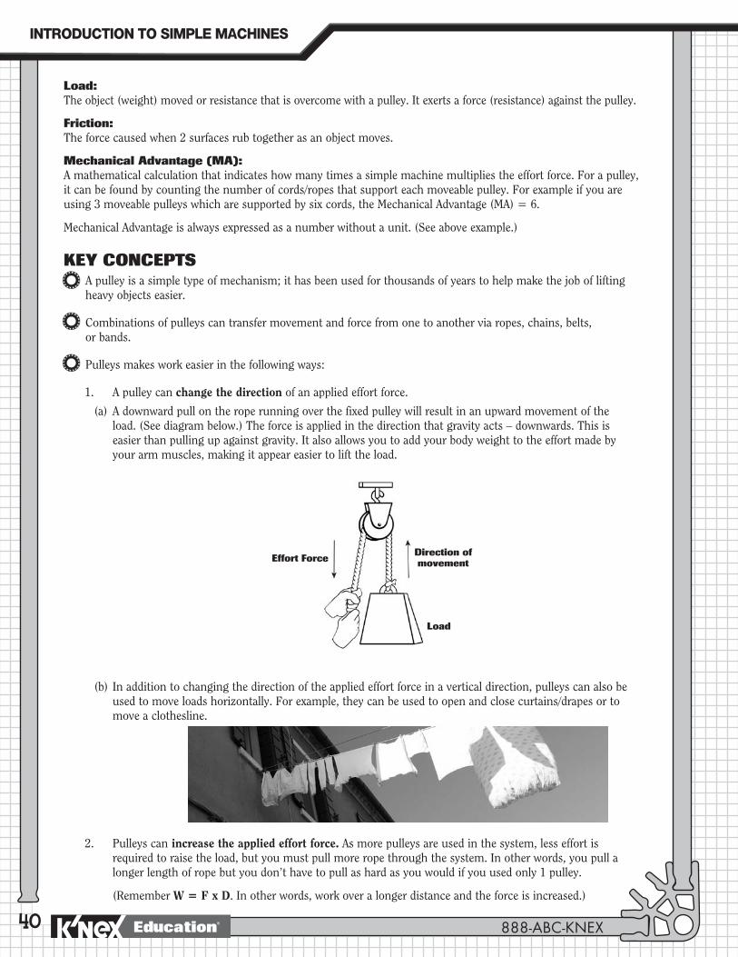
40
Load: The object (weight) moved or resistance that is overcome with a pulley. It exerts a force (resistance) against the pulley.
Friction: The force caused when 2 surfaces rub together as an object moves.
Mechanical Advantage (MA): A mathematical calculation that indicates how many times a simple machine multiplies the effort force. For a pulley, it can be found by counting the number of cords/ropes that support each moveable pulley. For example if you are using 3 moveable pulleys which are supported by six cords, the Mechanical Advantage (MA) = 6.
Mechanical Advantage is always expressed as a number without a unit. (See above example.)
KEY CONCEPTSA pulley is a simple type of mechanism; it has been used for thousands of years to help make the job of lifting heavy objects easier.
Combinations of pulleys can transfer movement and force from one to another via ropes, chains, belts, or bands.
Pulleys makes work easier in the following ways:
1. A pulley can change the direction of an applied effort force.
(a) A downward pull on the rope running over the fixed pulley will result in an upward movement of the load. (See diagram below.) The force is applied in the direction that gravity acts – downwards. This is easier than pulling up against gravity. It also allows you to add your body weight to the effort made by your arm muscles, making it appear easier to lift the load.
(b) In addition to changing the direction of the applied effort force in a vertical direction, pulleys can also be used to move loads horizontally. For example, they can be used to open and close curtains/drapes or to move a clothesline.
2. Pulleys can increase the applied effort force. As more pulleys are used in the system, less effort is required to raise the load, but you must pull more rope through the system. In other words, you pull a longer length of rope but you don’t have to pull as hard as you would if you used only 1 pulley.
(Remember W = F x D. In other words, work over a longer distance and the force is increased.)
Effort Force Direction of movement
Load
INTRODUCTION�TO�SIMPLE�MACHINES
Education® 888-ABC-KNEX

41
For example, with a system composed of 2 pulleys - one fixed and the other moveable – you need apply only half the effort force that would otherwise be needed to raise the load without the help of the pulleys, but you must pull twice the amount of rope. This is because the moveable pulley is supported by two sections of rope and you must move both sides of the rope to lift the load.
Upper pulley: Fixed
Effort Force
Effort
Effort
Effort
Fixed
Fixed
LoadLoadLoad
Moveable
Moveable
Load
Lower pulley: Moveable
Fixed to a supporting structure. Not directly attached to the load.
Attached directly to the load being lifted.
Two or more sets of pulleys connected by the same rope. The upper set comprises fixed pulleys attached to a supporting structure; the lower set(s) is moveable.
Do not move when the rope is pulled, other than to rotate in place.
Move when the rope is pulled. When the pulley moves, so does the load.
Upper set does not move; lower set(s) moves when the rope is pulled.
Effort is always applied by pulling down. This is easier because effort is applied in the same direction as the force of gravity.
With one moveable pulley, the effort force is applied by pulling upwards.
Effort is applied by pulling down.
Change the direction of the applied effort force. A downward pull on the rope results in an upward movement of the load.
Increase the force applied to the load.
Change the direction of the applied force and increase the force applied to the load.
Pulley Summary
FIXED PULLEYS MOVEABLE PULLEYS COMBINATION PULLEYS
PULLEYS�
www.knexeducat ion.com Education®
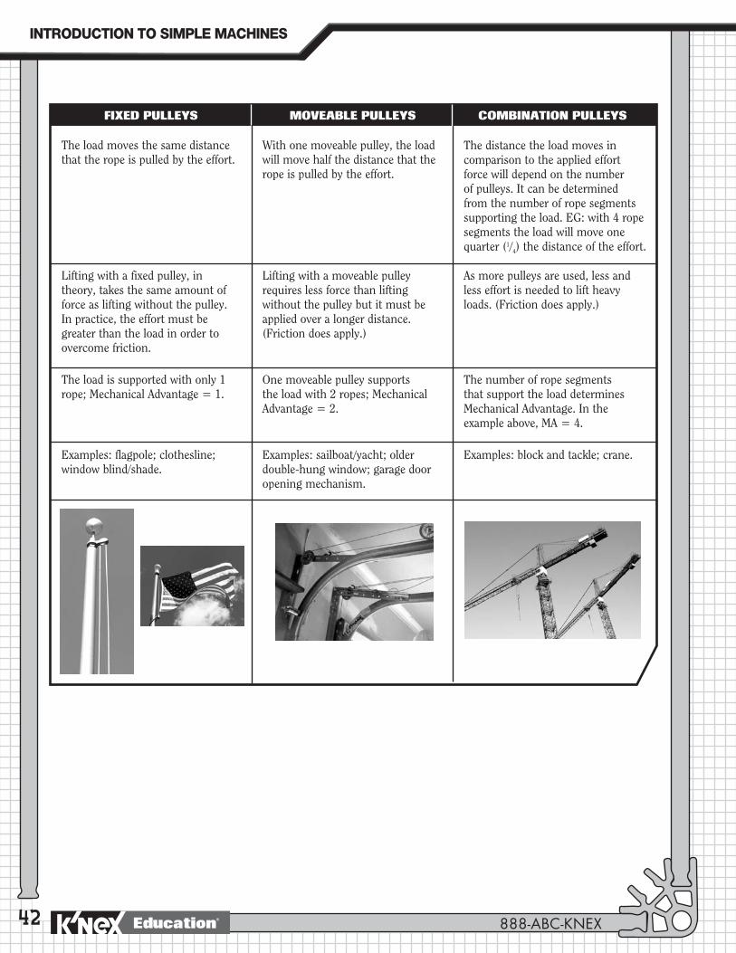
42
The load moves the same distance that the rope is pulled by the effort.
With one moveable pulley, the load will move half the distance that the rope is pulled by the effort.
The distance the load moves in comparison to the applied effort force will depend on the number of pulleys. It can be determined from the number of rope segments supporting the load. EG: with 4 rope segments the load will move one quarter (1/4) the distance of the effort.
Lifting with a fixed pulley, in theory, takes the same amount of force as lifting without the pulley. In practice, the effort must be greater than the load in order to overcome friction.
Lifting with a moveable pulley requires less force than lifting without the pulley but it must be applied over a longer distance. (Friction does apply.)
As more pulleys are used, less and less effort is needed to lift heavy loads. (Friction does apply.)
The load is supported with only 1 rope; Mechanical Advantage = 1.
One moveable pulley supports the load with 2 ropes; Mechanical Advantage = 2.
The number of rope segments that support the load determines Mechanical Advantage. In the example above, MA = 4.
Examples: flagpole; clothesline; window blind/shade.
Examples: sailboat/yacht; older double-hung window; garage door opening mechanism.
Examples: block and tackle; crane.
FIXED PULLEYS MOVEABLE PULLEYS COMBINATION PULLEYS
INTRODUCTION�TO�SIMPLE�MACHINES
888-ABC-KNEXEducation®
A Flagpole: An example of a fixed pulley.
The Flagpole
43
PROCEDUREIntroduction
Review with the students how many of the simple machines they have investigated make it easier to lift heavy objects.
Ask for a volunteer(s) to lie face down across a table/desk, next to one edge, and reach down on the side of the table/desk to lift up a bucket/basket filled with heavy objects. (Students should not extend an arm over the front of the table/desk.)
Ask the volunteer(s) to describe how difficult (or easy) this was for them.
Secure a rope to the bucket and ask them to pull up the bucket using the rope.
Encourage the students to consider ways in which this could be done more easily.
Explain that their task is to build a model that will demonstrate the use of a simple machine that can make the work of raising an object easier. As they construct the model, they should try to identify the simple machine they are building.
OBJECTIVESStudents will:1. Identify that pulleys are wheels with grooves around their outer rim.
2. Learn that pulleys can be used to lift objects and change the direction of movement.
3. Demonstrate how a fixed pulley functions.
4. Undertake measurements to discover whether or not a fixed pulley increases the applied effort force.
5. Identify examples of everyday objects that incorporate fixed pulleys.
MATERIALSEach group of 2 students will need: - 1 K’NEX Levers and Pulleys Building
Set with Building Instructions booklet
- Dot stickers or pieces of masking tape
- Measuring tape
- Student Journals
- 200 gram or 5 Newton spring scale (optional)
You will need:- A bucket or basket
filled with heavy objects.
Class IdeaYou may find it useful to create a word wall composed of the words and terms the students may need when discussing their investigations and findings and when making labeled drawings and written descriptions. Words could be written on cards with descriptors on the back.
PULLEYS�
www.knexeducat ion.com Education®

44
Inquiry Activity I: What is a pulley and what can it do?Steps
1. (a) Ask if anyone knows the name of the simple machine that is part of the model they have built.
(b) Introduce the students to the concept of a pulley. Ask them to describe the pulley that is in their model. (A wheel with a groove built into its rim. A string passes around the rim.) With the help of a labeled diagram drawn on the blackboard, explain how a pulley works. (See Key Terms and Definitions; Key Concepts.)
2. (a) Ask the students to look at the diagram and describe 2 things that the pulley can do.
(b) Ask the students to think back to their attempts to lift the heavy bucket. Ask why it might be easier to pull downwards rather than upwards on a rope.
(c) Encourage the students to do a search on the Internet for web sites that explain how pulleys work. (For example, visit the following site for information: http://www.wcsscience.com/pulley/page.html)
Students will have most likely read the information on Page 11 of the Building Instructions booklet and will have identified the pulley.
Students should answer that it helps to lift a heavy load. It alsochangesthedirectionofmovement–theeffortforceis applied in a downward direction, while the load moves in an upward direction.
Students should be helped to understand that when they pull downwards their body weight is added to the effort made by their arm muscles, making it appear easier to lift the load. You may also want to introduce the concept that they are pulling with gravity and not against it.
Building ActivityOrganize the class into teams of 2 students and distribute 1 K’NEX Levers and Pulleys Building Set to EACH group.
Invite the students to build the FLAGPOLE (Pages 10-11 of the Building Instructions booklet.) We recommend that one student build Steps 1-3 and the other, Steps 4-6. The parts should then be assembled, as shown, to form the completed flagpole.
NOTE: Students should NOT cut the string. They will need a long string for subsequent pulley building activities.
Provide the students with a few minutes to investigate the model and determine what it does.
Effort Force Direction of movement
Load
INTRODUCTION�TO�SIMPLE�MACHINES
Education® 888-ABC-KNEX

45
3. (a) Explain to the students that there are two types of pulleys:
i. Fixed: This type is attached to a wall or other structure and doesn’t move when the rope is pulled, although it may spin in place.
ii Moveable: This type, together with the load, moves when the rope is pulled.
(b) Ask the students to predict the category into which the pulley on the flagpole falls. They should write their thoughts in their journal. They should label the pulley on their model as fixed or moveable.
(c) If the students have attached the string to their pulley ask them to unfasten it for the next activity.
Inquiry Activity II: How does a fixed pulley make work easier?Steps
1. (a) Attach an object to one end of the black string. You can thread a K’NEX tire or a series of connectors onto it. On a piece of masking tape make and affix a label for the object – this is the LOAD. Lift the load by pulling on the string. The pulling force is the EFFORT you apply to do the work. Feel how much force or effort it takes to lift the load. What happens when you let go of the string? Take turns to lift the load.
(b) Now pass the string over the pulley at the top of the flagpole. (Note: the string does not have to be secured at the bottom of the flagpole.) Lift the load by pulling on the string. Feel how much effort is needed to lift the load. Take turns to do this.
(c) When you use the pulley, in which direction must you pull the string: up or down?
(b) Does the pulley make lifting easier? If so, how?
2. (a) Let the load rest on the red base of the flagpole and make sure that the string is pulled taut over the gray pulley.
(b) (b) One member of the team should grip the string just below the pulley and pull down slowly to lift the load. (Note: this should be done carefully so that the string does not slip off the pulley.) The other member of the team should use a measuring tape to record:
i. How far the string has been pulled. (Measure from your partner’s fingertips to the gray pulley.)
ii How far the load has been raised above the desktop.
The Flagpole
Students should discover that the pulley on the flagpole is fixed.
Students should answer that when using the pulley, they pull down on the string to raise the load. It feels easier to pull down on the string using the pulley because “body weight” can also be used to help the pulling forces. When pulling upwards only “muscle” power can be used. In fact, the same amount of effort is used in both cases.
Tire or Connectors String
PULLEYS�
www.knexeducat ion.com Education®
46
(c) What do you notice when you compare the measurements?
(d) Make a sketch of the experiment in your journals, labeling the pulley, the load, the applied effort force, and the directions of movement of the pulling force and the load being raised. Record your measurements.
3. Why do flagpoles have pulleys to raise and lower the flag? How would you get the flag to the top of a flagpole if you didn’t use a pulley?
Applying The IdeaOn the board review with the class what they have discovered about fixed pulleys:
1. Fixed pulleys change the direction of the applied effort force.
2. The load moves the same distance that the rope is pulled by the effort.
In their journals students should identify the type of pulley that is used in the flagpole. They should then explain how using a fixed pulley makes the work of lifting a load easier. Students should be encouraged to use correct vocabulary.
Arrange for the students to raise and lower the school’s flag. Make sure they know and observe proper flag etiquette.
Ask the students to investigate other places at school, at home, and in their community, where fixed pulleys can be used to lift an object. They should be encouraged to use the Internet to broaden their area of research.
Encourage the students to build a K’NEX model of one of these other fixed pulleys and explain how they work. Suggest that they think about how far they have to pull to lift the object a certain height.
Extending The IdeaUse the spring scale to measure the effort force used to lift the mass with and without the fixed pulley. Attach the scale to the load to measure the effort force required to lift it without the pulley. Then attach the spring scale to the end of the rope. Run the rope over the pulley and raise the load by pulling on the spring scale. If you do not obtain a significant reading on the scale, use a heavier object.
If the students tackle the extension activity they can add the following to their list of characteristics for fixed pulleys (see above):
3. Lifting with a fixed pulley takes the same amount of force as lifting without the pulley.
NOTE: If possible, retain one Flagpole model, with its fixed pulley, so that the students can compare it with the compound pulley system used in the Sailboat model on Page 49.
Suggestions for fixed pulley models: clothesline; pulley for blinds on windows.
Theoretically, the effort force should be equal in both cases. To lift a weight using a fixed pulley requires the effort force applied to the end of the rope to equal that of the weight on the other end. Due to friction, however, the force required, using the pulley, may be slightly higher.
Students should notice that the distance moved by the effort and the load is equal. Fixedpulleysonlychangethedirectionofmovement.
Students should be able to explain that it is easier to pull down on a rope to raise a flag than it is to climb a tall ladder to secure the flag to the top of the pole.
INTRODUCTION�TO�SIMPLE�MACHINES
888-ABC-KNEXEducation®
47
JOURNAL CHECK: 4 Definition and diagram of a pulley.
4 Prediction of the type of pulley used on a flagpole.
4 Labeled diagram of the flagpole’s fixed pulley system.
4 List of the characteristics of a fixed pulley.
4 Explanation of how a fixed pulley makes work easier.
The Flagpole
NOTES:
__________________________________________________________________________________________________
__________________________________________________________________________________________________
__________________________________________________________________________________________________
__________________________________________________________________________________________________
__________________________________________________________________________________________________
__________________________________________________________________________________________________
__________________________________________________________________________________________________
__________________________________________________________________________________________________
__________________________________________________________________________________________________
__________________________________________________________________________________________________
__________________________________________________________________________________________________
__________________________________________________________________________________________________
__________________________________________________________________________________________________
__________________________________________________________________________________________________
__________________________________________________________________________________________________
__________________________________________________________________________________________________
__________________________________________________________________________________________________
__________________________________________________________________________________________________
__________________________________________________________________________________________________
__________________________________________________________________________________________________
PULLEYS�
www.knexeducat ion.com Education®
48

A Sailboat: An example of the use of a compound pulley.
A Sailboat
49
PROCEDUREIntroduction
Review how the use of a pulley system helps make the job of raising a flag to the top of the pole easier. In this case, the pulley changes the direction of the effort force – it is easier to pull down on a rope than to pull up on one. The pulley also means that you don’t have to climb a ladder to reach the top of the pole.
Ask the students to look at the pictures of sailboats that they have collected, (or refer them to pictures that you have displayed on the classroom walls,) and ask them to describe how a sailboat operates.
OBJECTIVESStudents will:1. Identify the difference between fixed and moveable pulleys.
2. Learn that fixed and moveable pulleys, when used together, are known as compound pulleys.
3. Demonstrate how compound pulleys function.
4. Investigate how a compound pulley system increases the applied effort force and makes the job of lifting a load easier.
5. Learn that the greater the number of pulleys in a system the easier it is to lift heavy loads.
6. Identify examples of everyday objects that incorporate compound pulleys.
MATERIALSEach group of 2 students will need: - 1 K’NEX Levers and Pulleys
Building Set with Building Instructions booklet
- Dot stickers or pieces of masking tape
- Measuring tape
- Large paper clip
- Pictures of sailboats and ships
- Student Journals
- 200-400 gram or 5-10 Newton spring scale (optional)
You will need (optional):
- The Flagpole model from the previous building activity for comparison purposes
- Pictures of sailboats and sailing ships displayed around the classroom or available for viewing on a computer screen. (Suggestion: Visit www.anyboat.com/tall_ships_2000/tall_ships.htm to view images of tall ships under sail in Narragansett Bay, RI in 2000. Or, visit www.freefoto.com and search under Water Transport – tall ships.)
You may want to use this as an opportunity to introduce some vocabulary associated with sailboats: mast, bow, stern, boom, rigging, cleats etc.
PULLEYS�
www.knexeducat ion.com Education®
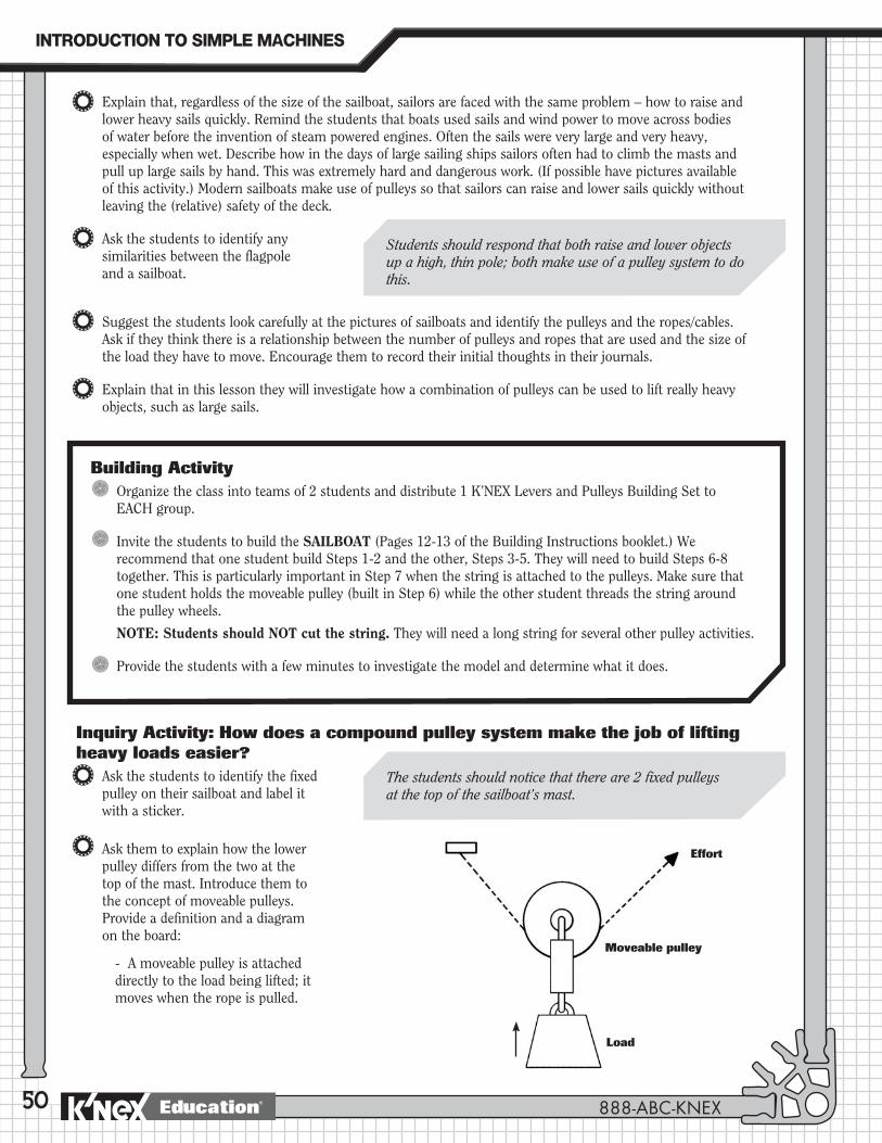
50
Explain that, regardless of the size of the sailboat, sailors are faced with the same problem – how to raise and lower heavy sails quickly. Remind the students that boats used sails and wind power to move across bodies of water before the invention of steam powered engines. Often the sails were very large and very heavy, especially when wet. Describe how in the days of large sailing ships sailors often had to climb the masts and pull up large sails by hand. This was extremely hard and dangerous work. (If possible have pictures available of this activity.) Modern sailboats make use of pulleys so that sailors can raise and lower sails quickly without leaving the (relative) safety of the deck.
Ask the students to identify any similarities between the flagpole and a sailboat.
Suggest the students look carefully at the pictures of sailboats and identify the pulleys and the ropes/cables. Ask if they think there is a relationship between the number of pulleys and ropes that are used and the size of the load they have to move. Encourage them to record their initial thoughts in their journals.
Explain that in this lesson they will investigate how a combination of pulleys can be used to lift really heavy objects, such as large sails.
Inquiry Activity: How does a compound pulley system make the job of lifting heavy loads easier?
Ask the students to identify the fixed pulley on their sailboat and label it with a sticker.
Ask them to explain how the lower pulley differs from the two at the top of the mast. Introduce them to the concept of moveable pulleys. Provide a definition and a diagram on the board:
- A moveable pulley is attached directly to the load being lifted; it moves when the rope is pulled.
Students should respond that both raise and lower objects up a high, thin pole; both make use of a pulley system to do this.
The students should notice that there are 2 fixed pulleys at the top of the sailboat’s mast.
Building ActivityOrganize the class into teams of 2 students and distribute 1 K’NEX Levers and Pulleys Building Set to EACH group.
Invite the students to build the SAILBOAT (Pages 12-13 of the Building Instructions booklet.) We recommend that one student build Steps 1-2 and the other, Steps 3-5. They will need to build Steps 6-8 together. This is particularly important in Step 7 when the string is attached to the pulleys. Make sure that one student holds the moveable pulley (built in Step 6) while the other student threads the string around the pulley wheels.
NOTE: Students should NOT cut the string. They will need a long string for several other pulley activities.
Provide the students with a few minutes to investigate the model and determine what it does.
Moveable pulley
Effort
Load
INTRODUCTION�TO�SIMPLE�MACHINES
888-ABC-KNEXEducation®
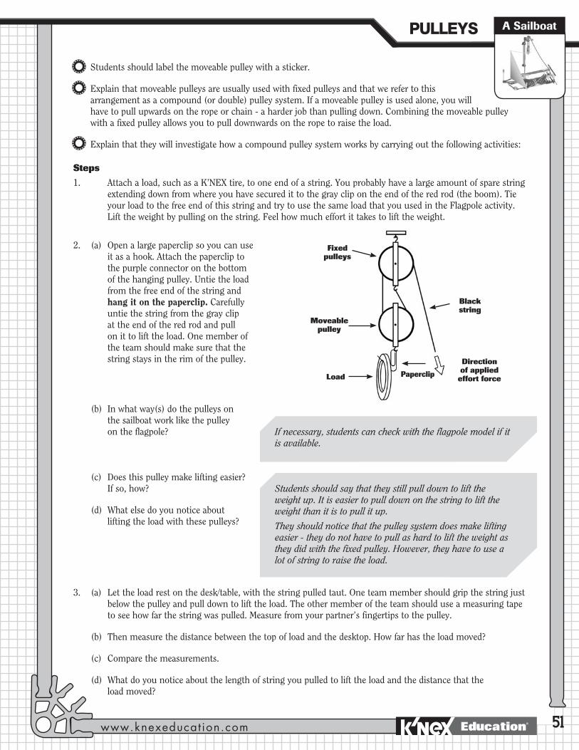
51
Students should label the moveable pulley with a sticker.
Explain that moveable pulleys are usually used with fixed pulleys and that we refer to this arrangement as a compound (or double) pulley system. If a moveable pulley is used alone, you will have to pull upwards on the rope or chain - a harder job than pulling down. Combining the moveable pulley with a fixed pulley allows you to pull downwards on the rope to raise the load.
Explain that they will investigate how a compound pulley system works by carrying out the following activities:
Steps
1. Attach a load, such as a K’NEX tire, to one end of a string. You probably have a large amount of spare string extending down from where you have secured it to the gray clip on the end of the red rod (the boom). Tie your load to the free end of this string and try to use the same load that you used in the Flagpole activity. Lift the weight by pulling on the string. Feel how much effort it takes to lift the weight.
2. (a) Open a large paperclip so you can use it as a hook. Attach the paperclip to the purple connector on the bottom of the hanging pulley. Untie the load from the free end of the string and hang it on the paperclip. Carefully untie the string from the gray clip at the end of the red rod and pull on it to lift the load. One member of the team should make sure that the string stays in the rim of the pulley.
(b) In what way(s) do the pulleys on the sailboat work like the pulley on the flagpole?
(c) Does this pulley make lifting easier? If so, how?
(d) What else do you notice about lifting the load with these pulleys?
3. (a) Let the load rest on the desk/table, with the string pulled taut. One team member should grip the string just below the pulley and pull down to lift the load. The other member of the team should use a measuring tape to see how far the string was pulled. Measure from your partner’s fingertips to the pulley.
(b) Then measure the distance between the top of load and the desktop. How far has the load moved?
(c) Compare the measurements.
(d) What do you notice about the length of string you pulled to lift the load and the distance that the load moved?
Fixed pulleys
Black string
Direction of applied
effort force
Moveable pulley
Load Paperclip
If necessary, students can check with the flagpole model if it is available.
Students should say that they still pull down to lift the weight up. It is easier to pull down on the string to lift the weight than it is to pull it up.
They should notice that the pulley system does make lifting easier - they do not have to pull as hard to lift the weight as they did with the fixed pulley. However, they have to use a lot of string to raise the load.
A SailboatPULLEYS�
www.knexeducat ion.com Education®

52
Suggestions for compound pulley models: elevator, drawbridge, garage door.
Possiblesummarystatement:Acompoundpulleychangesthedirectionoftheeffortforceanditincreasestheforceappliedtotheloadsothattheworkiseasiertodo.Theeffortforce,however,mustbeappliedoveragreaterdistance.
Students should notice that the distance the load moves is approximately half the length of string they pulled. The compound pulley reduces the effort needed to lift the load but increases the distance that the string is pulled. This is because the system has one movable pulley with two sections of string supporting its weight. Using this system, they have to pull the string half as hard to lift the load but have to pull it twicethedistance–thisisthetradeoff.
Real sailboats have a series of rings around their mast that are attached to a rope (halyard). The halyard is connected to the pulley system. The edges of the sails contain grommets (holes) through which clips are passed and hooked onto the rings around the mast. Pulling on the halyard raises the rings and the sail up the mast.
Students should notice that using the compound pulley helps to lift the sail quickly and easily. The sails are tall and heavy. The compound pulley is helpful on a sailboat since you have to adjust the heavy sails quickly because of changes in wind speed and direction.
(e) Why do you think this happened?
4. (a) How do real sailboats attach their sails to the pulley system?
(b) What do you notice about the size of the sails on the sailboat?
(c) Why do you think sailboats use a compound pulley system for raising and lowering sails?
Applying The IdeaAsk the students to record information about the type of pulley system used on a sailboat. They should be encouraged to draw labeled diagrams to demonstrate the different types of pulleys, the direction of the effort force, the direction of movement of the load, and the number of ropes involved in raising the load. They should include an explanation of how the moveable pulley is different from the fixed pulley.
Ask each group to select another compound pulley system and build a K’NEX model of it. They should explain how it works to the rest of the class. Encourage them to think about how far they have to pull to lift the object a certain height.
Review with the class how the compound pulley combines the advantages of both types of pulleys. They should understand that a compound pulley allows you to lift a very heavy weight while applying a small amount of force in the direction in which it is easiest to pull. Help the students to develop a summary statement and ask them to record it in their journals.
Ask the students to list other places where compound pulleys can be used to lift something heavy.
INTRODUCTION�TO�SIMPLE�MACHINES
888-ABC-KNEXEducation®
53
JOURNAL CHECK
4 Definition and a diagram of a moveable pulley.
4 Description, with diagram, of the sailboat’s compound pulley system.
4 Measurements to demonstrate how the compound pulley makes it easier to raise a heavy load.
4 Summary statement about the advantages of a compound pulley system.
4 Everyday examples of the use of compound pulleys to raise heavy loads.
NOTES:
_______________________________________________________________________________________________
_______________________________________________________________________________________________
_______________________________________________________________________________________________
_______________________________________________________________________________________________
_______________________________________________________________________________________________
_______________________________________________________________________________________________
_______________________________________________________________________________________________
_______________________________________________________________________________________________
_______________________________________________________________________________________________
_______________________________________________________________________________________________
_______________________________________________________________________________________________
_______________________________________________________________________________________________
Extending The Idea
1. Using the library and Internet, investigate different types of sailing vessels like catamarans and the America’s Cup sailboat. Determine how many sails are used and why, how the sails are arranged and what the sail arrangement helps the boat accomplish. Using K’NEX, build another sailing vessel. Demonstrate the sail arrangement using multiple sets of compound pulleys. Explain how the sail arrangement helps your sailboat move across the water.
2. (a) Design a sail for your sailboat using cloth and markers. Use pictures of sailboats to find ideas for designs and shapes.
(b) Decide how to attach your sail to the sailboat’s string.
(c) Raise and lower the sail on your boat and notice what happens.
A SailboatPULLEYS�
www.knexeducat ion.com Education®
54

The Block and Tackle: An example of the use of a compound pulley.
Block & Tackle
55
PROCEDUREIntroduction
Review the results of the previous lesson in which the students discovered that a compound pulley system reduced the effort needed to lift the load but increased the distance that the string or rope was pulled.
Show, or ask the students to find, photographs and pictures of cranes at work. (Visit www.freefoto.com and http://pics.tech4learning.com for photographs of cranes.)
OBJECTIVESStudents will:1. Identify the types of pulleys used in a block and tackle system.
2. Demonstrate how fixed and moveable pulleys function in a block and tackle.
3. Differentiate between a block and tackle system and other pulley systems.
4. Identify the relationship between the number of supporting strings and the amount of applied effort force required to raise a load.
MATERIALSEach group of 2 students will need: - 1 K’NEX Levers and Pulleys
Building Set with Building Instructions booklet
- Dot stickers or pieces of masking tape
- Measuring tape
- Paper cup
- 1 or 2 pieces of aluminum foil (Approx. 6 x 8 inches/ 15 x 20 cms.)
- Colored marker
- Pennies or washers (approximately 30 pennies will be needed.)
- Student Journals
- 200 gram or 5 Newton spring scale (optional)
NOTE: Make sure that you have a plentiful supply of pennies or washers available for this activity.
PULLEYS�
www.knexeducat ion.com Education®

56
Ask the students to describe the pulley systems the cranes use and the jobs they have to do. What type of objects do they lift?
Ask them to infer why pulley systems make it easier to lift heavy loads.
Explain that a crane uses a ‘block and tackle’ mechanism to make the job of lifting very heavy loads easier. Provide a definition of a block and tackle:
A specific combination of pulleys used to lift very heavy objects. The block is the frame holding the pulleys; the tackle is the rope or cable.
Ask the students to turn to Page 15 of their Building Instructions booklet where they will find the plan of the block and tackle that they will build in their next activity. Explain how the block and tackle is constructed by winding a rope or chain around a number of fixed and moveable pulley wheels. Ask them to do the following:
Write in your journals how many times you think the force on the load will be increased by this machine. HINT: Remember what you discovered last lesson about the moveable pulley and the number of supporting ropes. We will check to see if you are correct when we investigate the model.
NOTE: Do not discuss the answer with the students at this point in the lesson. The correct answer is 4 times. The multiplication can be found by counting the number of lengths of rope supporting the moveable pulleys. In this example, there are 2 moveable pulleys, each with two supporting ropes = 4. (The three pulleys at the top are fixed pulleys.)
Inquiry Activity: How does a block and tackle make the job of lifting very heavy loads easier?
Ask each group to identify and label the fixed and moveable pulleys in their model.
Ask the students to infer how using a number of fixed and moveable pulleys in a lifting mechanism will affect their ability to lift a load.
Building ActivityOrganize the class into teams of 2 students and distribute 1 K’NEX Levers and Pulleys Building Set to EACH group.
Invite the students to build the BLOCK and TACKLE (Pages 14-15 of the Building Instructions booklet.) We recommend that one student build Steps 1-3 and the other, Steps 4-5. They will need to build Steps 6-8 together. This is particularly important in Step 7 when the string is attached to the pulleys.
BUILDING TIP 1: When stringing the pulleys the students should place a large book on one side of the base of the model to keep it from moving around on the desktop.
BUILDING TIP 2: We recommend that after attaching the string to the gray snap, you pass it through the bottom left hole in the yellow connector (located in the center of the upper support). Then pass the string over the pulleys as indicated in the Building Instructions booklet. Finally pass the string back through the bottom right hole in the yellow connector and attach it to the gray snap. (Step 8 in the Building Instructions booklet.)
Allow the students a few minutes to investigate the model and determine what it does.
INTRODUCTION�TO�SIMPLE�MACHINES
888-ABC-KNEXEducation®

57
Steps
1. (a) Give each group a piece of aluminum foil filled with pennies (or washers) and ask each student to take turns to place this on the palm of his or her hand and to raise and lower it to gain an impression of the load that will be lifted by their model and the forces needed to raise it. If spring scales are available these should be used to find the weight of the load.
2. Next, try lifting the load using your K’NEX Block and Tackle model.
(a) Place your block and tackle stand on the edge of your desk so that the pulleys hang out over the desk’s edge. Place a book on the other side to hold it down. (See Page 15 of Building Instructions booklet.)
(b) Wrap the outside of the basket with a piece of aluminum foil and place the pennies (or washers) inside the basket. Lift the basket by pulling on the string. Feel how much force it takes to lift the load.
(c) How does lifting the load using the block and tackle compare to lifting it by hand?
3. Explain that the students will experiment with their model to quantify how much effort is needed to raise the load of pennies using the pulley system they have built. Explain that first they need to find the weight of the basket when it is empty. Then they will add pennies to the basket and find the total weight of the load. They should follow these steps:
Measuring the weight of the empty basket:
(a) Remove the pennies from the basket and put them to one side – you will use them again later.
(b) Untie the string from the gray snap at the back of the base and tie it around the rim of a small paper cup.
(c) Hook the string over one of the 3 fixed pulleys at the top of the model; then tie the other end to the space between the 2 moveable pulleys.
(d) Check to make sure that the model is on the edge of the desk, the pulleys are hanging over the edge, and a heavy book securely balances the model.
(e) Make sure the sides and bottom of the empty basket are covered with a piece of aluminum foil. (Or place a small paper cup inside the basket.)
(f) Start placing pennies into the empty cup until the weight is sufficient to cause the basket of the model to move upwards.
(g) Notice the distance that the load (basket) moves and the effort (cup with pennies) moves.
(h) Record the number of pennies you placed into the cup. This represents the weight of the basket.
Fixed pulley wheels
String hooked over a fixed pulley
String tied to the beam between moveable pulleys
Moveable pulley wheels
Basket covered with foil
Paper cup attached to string
Block & TacklePULLEYS�
www.knexeducat ion.com Education®
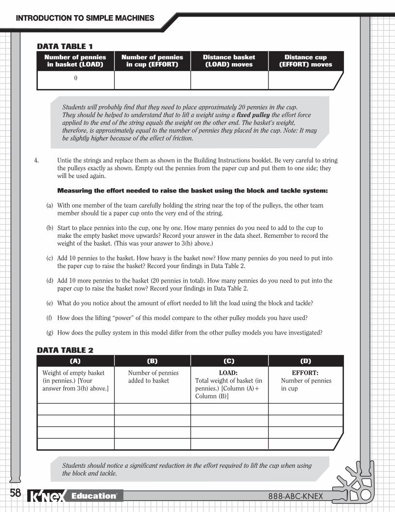
58
4. Untie the strings and replace them as shown in the Building Instructions booklet. Be very careful to string the pulleys exactly as shown. Empty out the pennies from the paper cup and put them to one side; they will be used again.
Measuring the effort needed to raise the basket using the block and tackle system:
(a) With one member of the team carefully holding the string near the top of the pulleys, the other team member should tie a paper cup onto the very end of the string.
(b) Start to place pennies into the cup, one by one. How many pennies do you need to add to the cup to make the empty basket move upwards? Record your answer in the data sheet. Remember to record the weight of the basket. (This was your answer to 3(h) above.)
(c) Add 10 pennies to the basket. How heavy is the basket now? How many pennies do you need to put into the paper cup to raise the basket? Record your findings in Data Table 2.
(d) Add 10 more pennies to the basket (20 pennies in total). How many pennies do you need to put into the paper cup to raise the basket now? Record your findings in Data Table 2.
(e) What do you notice about the amount of effort needed to lift the load using the block and tackle?
(f) How does the lifting “power” of this model compare to the other pulley models you have used?
(g) How does the pulley system in this model differ from the other pulley models you have investigated?
Students will probably find that they need to place approximately 20 pennies in the cup. They should be helped to understand that to lift a weight using a fixedpulley the effort force applied to the end of the string equals the weight on the other end. The basket’s weight, therefore, is approximately equal to the number of pennies they placed in the cup. Note: It may be slightly higher because of the effect of friction.
Students should notice a significant reduction in the effort required to lift the cup when using the block and tackle.
Number of pennies Number of pennies Distance basket Distance cup in basket (LOAD) in cup (EFFORT) (LOAD) moves (EFFORT) moves
0
DATA TABLE 1
DATA TABLE 2 (A) (B) (C) (D)
Weight of empty basket (in pennies.) [Your answer from 3(h) above.]
Number of pennies added to basket
LOAD: Total weight of basket (in pennies.) [Column (A)+ Column (B)]
EFFORT: Number of pennies in cup
INTRODUCTION�TO�SIMPLE�MACHINES
888-ABC-KNEXEducation®

59
Block & Tackle
5. (a) Using the block and tackle, lift the basket 3 inches (7.6 cm).
(b) How far did you have to pull the string to reach this height?
6. (a) Count the number of strings supporting the movable pulleys in the block and tackle.
(b) Remembering what you discovered in the last lesson, what do the number of strings supporting the moveable pulleys tell you about how many times the force on the load is increased.
(c) How does your answer compare to your findings in Step 4.
7. (a) Add more pulleys to your block and tackle.
(b) How does this affect lifting the load and the distance you pull the rope?
Applying The IdeaReview observations with the students. Ask them to check their initial thoughts concerning how much the block and tackle would increase the force on the load.
Ask the students to:
(a) Describe and explain their observations.
(b) Make labeled drawings of their model.
(c) Add arrows to their drawing to indicate the direction of movement.
(d) Explain how the block and tackle is different from the other types of pulleys.
Remind them to use the correct terminology to describe the different components of the system.
Students should count 4 strings supporting the two movable pulleys. This means that this block and tackle makes it 4 times easier to lift the mass, but they also have to pull the rope 4 times further than if they were using a fixed pulley. Their results from Step 4 should have validated this: 10 pennies (the effort) could raise a loadwithatotalweightof40pennies–theblockandtacklemadethejob4timeseasier.
If students add more movable pulleys, they will notice that lifting is easier but they must pull the rope further to reach the same height as before.
Adding more moveable pulleys to the block and tackle combination makes the work of lifting a load easier. This K’NEX Block and Tackle model makes it 4 times easier to lift the load by increasing force on the load, but you have to pull the string 4 times the distance that the load moves. This is the tradeoff–lesseffortisappliedoveragreaterdistance.
To lift the basket 3 inches (7.6 cm) with a block and tackle with two movable pulleys, students will have to pull approximately 12 inches [30.5 cm].
NOTE: Due to friction exact measurements will be difficult to obtain.
Measure this distance
Measure this height
PULLEYS�
www.knexeducat ion.com Education®

60
JOURNAL CHECK
4 Definition of a block and tackle.
4 Labeled diagram of their block and tackle model showing direction of movements.
4 Measurements for lifting the load using the block and tackle.
4 Explanation of how the block and tackle makes the job of lifting easier.
4 Explanation of how a block and tackle is different from other pulleys.
4 Everyday uses of a block and tackle system.
Ask the students to describe situations where a block and tackle would be useful and to explain why they think the situation would require this kind of pulley system.
Suggest that they build a K’NEX model of a machine that uses a block and tackle. Ask them to explain how the machine works and how their machine stores all the extra string used in a block and tackle system.
Extending The Idea
1. Use the spring scale to measure the effort force used to lift the weight with and without the block and tackle. Attach the scale to the basket to measure the effort force required to lift it with just the fixed pulley. Then attach it to the end of the rope. Run the rope through the block and tackle system and pull it up by pulling on the spring scale. The effort force using the block and tackle should be one quarter of what it was using just the fixed pulley, (it will actually be more than one quarter due to friction,) although you have to pull further to get the weight to the same height. If you are not getting a significant reading on the scale, use a heavier object.
2. Ask the students to add more pulleys to the system and determine how that affects the force measurements.
3. Encourage the class to extend their research further by visiting www.howstuffworks.com and doing a search using the key word: ‘pulley’.
Building ChallengeYour mother is a physical therapist. She works with people who have been injured and have to use wheelchairs. It is difficult for your mother to lift the patients out of their wheelchairs to the different machines for their exercises. Using K’NEX and other materials design and build a portable pulley system that lifts the patients out of their wheel chairs and transports them to the different exercise machines. Explain how your machine operates and how it uses pulleys to accomplish the task.
Block and tackle systems are used to lift very heavy objects such as a car engine or a piano.
Suggestion for block and tackle models: crane.
INTRODUCTION�TO�SIMPLE�MACHINES
888-ABC-KNEXEducation®
Related Documents