1 CHAPTER 1 INTRODUCTION 1.1 INTRODUCTION Electrical Discharge Machine (EDM) is now become the most important accepted technologies in manufacturing industries since many complex 3D shapes can be machined using a simple shaped tool electrode. Electrical discharge machine (EDM) is an important ‘non-traditional manufacturing method’, developed in the late 1940s and has been accepted worldwide as a standard processing manufacture of forming tools to produce plastics moldings, die castings, forging dies and etc. New developments in the field of material science have led to new engineering metallic materials, composite materials, and high tech ceramics, having good mechanical properties and thermal characteristics as well as sufficient electrical conductivity so that they can readily be machined by spark erosion. At the present time, Electrical discharge machine (EDM) is a widespread technique used in industry for high- precision machining of all types of conductive materials such as: metals, metallic alloys, graphite, or even some ceramic materials, of whatsoever hardness. Electrical discharge machine (EDM) technology is increasingly being used in tool, die and mould making industries, for machining of heat treated tool steels and advanced materials (super alloys, ceramics, and metal matrix composites) requiring high precision, complex shapes and high surface finish. Traditional machining technique is often based on the material removal using tool material harder then the work material and is unable to machine them economically. An electrical discharge machining (EDM) is based on the eroding effect of an electric spark on both the electrodes used. Electrical discharge machining (EDM) actually is a process of utilizing the removal phenomenon of electrical-discharge in dielectric. Therefore, the electrode plays an important role, which affects the material removal rate and the tool wear rate [4].

Welcome message from author
This document is posted to help you gain knowledge. Please leave a comment to let me know what you think about it! Share it to your friends and learn new things together.
Transcript
1
CHAPTER 1
INTRODUCTION
1.1 INTRODUCTION
Electrical Discharge Machine (EDM) is now become the most important
accepted technologies in manufacturing industries since many complex 3D shapes
can be machined using a simple shaped tool electrode. Electrical discharge machine
(EDM) is an important ‘non-traditional manufacturing method’, developed in the late
1940s and has been accepted worldwide as a standard processing manufacture of
forming tools to produce plastics moldings, die castings, forging dies and etc. New
developments in the field of material science have led to new engineering metallic
materials, composite materials, and high tech ceramics, having good mechanical
properties and thermal characteristics as well as sufficient electrical conductivity so
that they can readily be machined by spark erosion. At the present time, Electrical
discharge machine (EDM) is a widespread technique used in industry for high-
precision machining of all types of conductive materials such as: metals, metallic
alloys, graphite, or even some ceramic materials, of whatsoever hardness. Electrical
discharge machine (EDM) technology is increasingly being used in tool, die and
mould making industries, for machining of heat treated tool steels and advanced
materials (super alloys, ceramics, and metal matrix composites) requiring high
precision, complex shapes and high surface finish. Traditional machining technique
is often based on the material removal using tool material harder then the work
material and is unable to machine them economically. An electrical discharge
machining (EDM) is based on the eroding effect of an electric spark on both the
electrodes used. Electrical discharge machining (EDM) actually is a process of
utilizing the removal phenomenon of electrical-discharge in dielectric. Therefore, the
electrode plays an important role, which affects the material removal rate and the
tool wear rate [4].
2
1.2 PROJECT BACKGROUND
Electrical discharge machine (EDM) is commonly used in tool, die and
mould making industries for machining heat-treated tool steel materials. The heat-
treated tool steels material falls in the difficult-to-cut material group when using
conventional machining process. The high rate of tool wear is one of the main
problems in electrical discharge machine (EDM). The wear ratio defined as the
volume of metal lost from the tool divided by the volume of metal removed from the
work material, varies with the tool and work materials used. If the rate of tool wear is
high means that the material is easy to wear and not good for machining performance
[3].
The significant of this study is to promote the consideration of electrode
selection in electrical discharge machine (EDM) machine for advance machining in
the manufacturing industries. This is because every electrode materials have their
own characteristic that lead to different result due to its properties. Electrical
discharge machine (EDM) has been analyzed since several years in order to improve
the material removal rate and the wear ratio, which are the most critical aspects of
the process. In the machining of electrical discharge machine (EDM), there are a few
characteristics which influence the machining process. Most important are the
material removal rate (MRR) and electrode wear ratio (EWR). These characteristics
should be taken into account when good machining performance is needed [10].
The case studies of this project are to determine the best material removal rate
(MRR) and electrode wear ratio (EWR) from different selection materials. This
would lead to the better process and product finishing. In other words, if we can
determine the best material removal rate (MRR) and electrode wear ratio (EWR), the
best performance of machining for electrical discharge machine (EDM) can be
archived. However, the machining characteristics of electrical discharge machine
(EDM) remain unclear, especially in regard to the total energy of discharge pulses
and tool electrode wear, since the energy is not only used to machine the work piece,
but also degrades the tool electrode [10]. Hence, some investigation needs to do to
find the best electrode for best performance in machining using electrical discharge
machining (EDM). Generally, the summary of the literature review have found that
3
the higher material removal rate (MRR) and the lower electrode wear ratio (EWR)
are the better for machining process performances.
1.3 PROBLEM STATEMENT
In electrical discharge machine (EDM), improper choose of the electrode
material may cause of poor machining rate or performance. This is due to material
removal rate (MRR) characteristic. Less material removal rate (MRR) needs more
time for machining process and become waste and not goods for production. The
second problem is it will decrease the accuracy of the product because influence of
the electrode wear ratio (EWR) characteristic. The accuracy of the product occurs
maybe because the electrode wear ratio (EWR) is high or material removal rate
(MRR) is not suitable. Furthermore, electrode wear imposes high costs on
manufacturers to substitute the eroded complicated electrodes by new ones for die
making. In order to increase the machining efficiency, erosion of the work piece
must be maximized and that of the electrode minimized in EDM process. Therefore,
studying the electrode wear and related significant factors would be effective to
enhance the machining productivity and process reliability.
1.4 OBJECTIVE
The objective of this project is to determine the proper electrode material for
machining tool steels work pieces using electrical discharge machining (EDM).
When the best electrode can be determine, it would lead to better process
performance in electric discharge machining (EDM). To archive this, the
characteristic of machining must be determine because the higher material removal
rate (MRR) and less electrode wear ratio (EWR) will lead to better performance.
1.5 PROJECT SCOPES
The research scope is limited to: Machining parameters refers to electrical
parameters on electrical discharge machine (EDM) i.e. polarity, pulse-on-duration,

4
discharge current, discharge voltage. The scope should be limited in this experiment
due to low cost and time. Beside, there are three tool electrode used that are
Aluminum, brass and cooper. The reason for using these only three materials is
regarding to cost limitation and availability. This is also including calculation of the
machining characteristics i.e. material removal rate (MRR) and electrode wear ratio
(EWR). The calculation is needed to analyze the result and data collections.
Beside, this paper project hopefully can gain a lot of understanding and get
more knowledge about the electric discharge machine (EDM). This is important to
get familiar with this method nowadays. Among the non-traditional methods of
material removal processes, electrical discharge machining (EDM) has drawn a great
a deal of researchers’ attention because of its broad industrial applications. This
process is well suited for machining of casting and forging dies, powder metallurgy
and injection molds, and aerospace parts.
1.6 SUMMARY
Chapter 1 has been discussed briefly about project background, problem
statement, objective and scope of the project. This chapter is as a fundamental for the
project and act as a guidelines for project research completion. Generally, this thesis
consists of five chapters. Chapter 1 that has you read is the introduction about this
study. Chapter 2 is the review of literature which discusses methods and findings
previously done by other people which are related to the study. Chapter 3 is the
Methodology which explains the approaches and methods used in performing the
thesis. Chapter 4 is the chapter which reports the outcomes or results and discussion
from the project and chapter 5 consists of the recommendation and conclusion.

5
CHAPTER 2
LITERATURE REVIEW
2.1 INTRODUCTION
Literature review is one of the scope studies. It works as guide to run this
analysis. It will give part in order to get the information about electrical discharge
machine (EDM) and will give idea to operate the test. From the early stage of the
project, various literature studies have been done. Research journals, books, printed
or online conference article were the main source in the project guides. This part will
include almost operation including the test, history, machining properties and results.
History of the electrical discharge machine (EDM) will be story little bit in this
section. Literature review section work as reference, to give information and guide
base on journal and other source in the media.
2.2 HISTORY OF ELECTRICAL DISCHARGE MACHINE (EDM)
The history of EDM Machining techniques goes as far back as the 1770s
when it was discovered by an English Scientist. However, Electrical Discharge
Machining was not fully taken advantage of until 1943 when Russian scientists
learned how the erosive effects of the technique could be controlled and used for
machining purposes. When it was originally observed by Joseph Priestly in 1770,
EDM Machining was very imprecise and riddled with failures. Commercially
developed in the mid 1970s, wire EDM began to be a viable technique that helped
shape the metalworking industry we see today. In the mid 1980s, the EDM
techniques were transferred to a machine tool. This migration made EDM more
widely available and appealing over traditional machining processes [6].
6
2.3 ELECTRICAL DISCHARGE MACHINE (EDM)
Electrical discharge machine (EDM) is a modern machine that can drilling,
milling, grinding, and other traditional machining operation. EDM now become the
most important accepted technologies in manufacturing industries since many
complex 3D shapes can be machined using a simple shaped tool electrode. In
manufacturing industry, Electro Discharge Machining (EDM) is commonly used for
producing mould and die component. This machine is use because the ability of the
machining process that is very accurate in creating complex or simple shape within
parts and assemblies. The cost of machining is quite high payable to its initial
investment and maintenance for the machine but very desirable machining process
when high accuracy is required. Since electrical discharge machining (EDM) was
developed, much theoretical and experimental work has been done to identify the
basic processes involved. It is now one of the main methods used in die production
and has good accuracy and precision with no direct physical contact between the
electrodes so that no mechanical stress is exerted on the work piece. The important
output parameters of the process are the material removal rate (MRR) and tool
electrode wear ratio (EWR) [10].
2.4 ELECTRIC DISCHARGE MACHINE (EDM) PROCESS
The electrical discharge machine (EDM) removes work piece by an electrical
spark erosion process. Common methods of evaluating machining performance in
EDM operation are based on the following performance characteristic: MRR, SR,
and EWR. Basically, this characteristics’ are correlated with the machining
parameters such as work piece polarity, pulse on time, duty factor, open discharge
voltage, discharges current and dielectric fluid. Proper selection of the machining
parameters can obtain higher material removal rate, better surface roughness, and
lower electrode wear ratio [10]. Machining takes place by the discharge pulse from
the cathode to the anode. Usually, the polarity is set, so that the work piece acts as
the anode and the tool electrode acts as the cathode, in order to obtain a higher
material removal rate. The discharge pulse gap is relatively small, thus the accuracy
of components or parts manufactured by EDM is very high. EDM is a thermo-

7
electrical material removal process, in which the tool electrode shape is reproduced
mirror wise into a work material, with the shape of the electrode defining the area in
which the spark erosion will occur [14]. EDM is accomplished with a system
comprising two major components: a machine tool and power supply. The machine
tool holds a shaped electrode, which advances into the work material and produces a
high frequency series of electrical spark discharges. The sparks are generated by a
pulse generator, between the tool electrode and the work material, submerged in a
liquid dielectric, leading to metal removal from the work material by thermal erosion
or vaporization [14]. The EDM phenomenon, as it is understood, can be divided into
three stages namely application of adequate electrical energy, dielectric breakdown,
sparking, and expulsions (erosion) of work material [14]. The spark erosion of the
work material makes use of electrical energy, converting them into thermal energy
through a series of repetitive electrical discharges between the tool electrode and the
work material electrode [14]. The thermal energy generates a channel of plasma
between the two electrodes, at a temperature ranging from 8000 to 12,000 ◦C, and as
high as 20,000 ◦C [8]. When the pulsed DC supply ∼20,000-30,000 Hz, is switched
off, the breakdown of plasma channel occurs, resulting in a sudden reduction in the
temperature, allowing the circulating dielectric fluid to flush away the molten work
material from the EDM machined surface in form of microscopic debris. Melting and
vaporization of the work material dominates the material removal process in EDM,
leaving tiny craters on the surface of the work material. EDM has no contact and no
cutting force process, and therefore does not makes direct contact between tool
electrode and the work material. This eliminates the chances of mechanical stress,
chatter and vibration problems, as is prominent in traditional machining. Material
removal rate (MRR) for EDM operation is somewhat slower than with traditional
machining methods, where chips are produced mechanically. The rate of material
removal is dependent upon the following factors: amount of pulsed current in each
discharge, frequency of the discharge, electrode material, work material and
dielectric flushing condition. Diameter overcut (dimensional accuracy) becomes
important when close tolerance components are required to be produced for space
application and also in tools, dies and moulds for press work, plastic molding and die
casting. EDM does not induce any mechanical stresses during EDM thereby
providing an additional advantage in the manufacture of intricate and complex-

8
shaped products [14]. Electrode wear takes place during the EDM operation when
the electrode (i.e. the tool) gets eroded due to the sparking action. The rate at which
the electrode wears is considerably less than that of the work material. In EDM, each
electrical spark discharge produces a tiny spherical crater in the work material by
local melting and vaporization. With high sparking frequencies the spark erosion
gives substantial metal removal rates. The depth of the crater defines the surface
finish which in turn depends on the current, frequency, and finish of the electrode.
The metal removal rates and surface finish are controlled by the frequency and
intensity of the spark. It has been found that high frequency and low amperage
settings give the best surface finish. High amperage leaves a larger crater having
large diameter and depth in a random location [14]. Surface finish produced on
machined surface plays an important role in production. It becomes more desirable
so as to produce a better surface when hardened materials are machined, requiring no
subsequent polishing. Surface finish is also important in the case of tools and dies for
molding as well as drawing operations. Surface roughness and dimensional accuracy
of a spark-eroded work material depend on discharge currents, electrode materials
and electrode polarity. With EDM processes, work piece surface modifications can
be well controlled,[7] and highly accurate geometric predictions can also be made
[8]. However, the machining characteristics of EDM remain unclear, especially in
regard to the total energy of discharge pulses and tool electrode wear, since the
energy is not only used to machine the work piece, but also degrades the tool
electrode. Hence, the accuracy of the components machined by EDM is also
influenced by the wear of the tool electrode [7, 8] From the literature survey, it has
been observed that no extensive work has been done with different tool electrode
materials on the work material steel (used for cold forming rolls, Knurling tools,
press tools, lathe centre’s, etc.). There exists a great need for investigating the effect
of various electrode materials and pulsed discharge currents on material removal
rate, diameter overcut, electrode wear and surface roughness in electric-discharge
machining of tool steel.
9
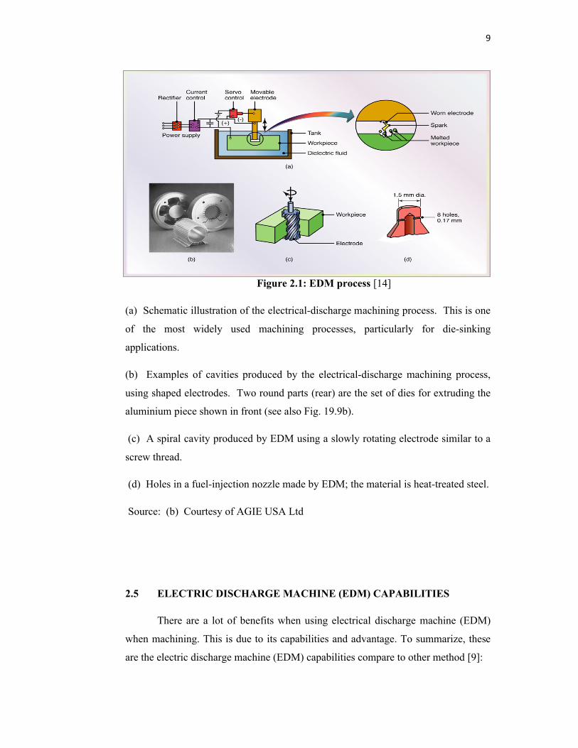
Figure 2.1: EDM process [14]
(a) Schematic illustration of the electrical-discharge machining process. This is one
of the most widely used machining processes, particularly for die-sinking
applications.
(b) Examples of cavities produced by the electrical-discharge machining process,
using shaped electrodes. Two round parts (rear) are the set of dies for extruding the
aluminium piece shown in front (see also Fig. 19.9b).
(c) A spiral cavity produced by EDM using a slowly rotating electrode similar to a
screw thread.
(d) Holes in a fuel-injection nozzle made by EDM; the material is heat-treated steel.
Source: (b) Courtesy of AGIE USA Ltd
2.5 ELECTRIC DISCHARGE MACHINE (EDM) CAPABILITIES
There are a lot of benefits when using electrical discharge machine (EDM)
when machining. This is due to its capabilities and advantage. To summarize, these
are the electric discharge machine (EDM) capabilities compare to other method [9]:
10
• Material of any hardness can be cut
• High accuracy and good surface finish are possible
• No cutting forces involved
• Intricate-shaped cavities can be cut with modest tooling costs
• Holes completed in one “pass”
2.6 ELECTRIC DISCHARGE MACHINE (EDM) LIMITATIONS
But, when using electric discharge machine (EDM) when machining there are
a few limitation. These are electric discharge machine (EDM) limitation [9]:
• Limited to electrically conductive materials
• Slow process, particularly if good surface finish and high accuracy are
required
• Dielectric vapour can be dangerous
• Heat Affected Zone (HAZ) near cutting edges
• Die sinking tool life is limited.
2.7 OPTIMIZATION PERFORMANCE
The complexity EDM and the number of the involved parameters require an
accurate analysis for assessing the process performance. The effects of electrode
material and flushing, in conjunction with electrode size and depth of cut, upon
productivity, electrode wear and surface quality have been evaluated through a
complete factorial experiment. The analysis has considered separately roughing and
finishing regimes, by adopting the operative conditions usually recommended in
industrial production. Productivity and electrode wear were measured by features
especially and differently defined for roughing and finishing regimes. Surface quality
11
was assessed only for finishing, by adopting three height parameters and three form
parameters. The experiment yields the following main conclusions [3]:
*The electrode material has significant influence in finishing operations on
wear and height roughness parameters.
*In all the experiments the effect of the electrode size resulted relevant on
productivity and electrode wear [3].
From the research of journals, the hypothesis can be made regarding machining
performance is the wear ratio of the electrode becomes small for the electrode
material with high boiling point, high melting point, and high thermal conductivity.
The higher thermal conductivity of the electrode ensures a better spark discharge
energy distribution during the EDM process. This will increase material removal rate
(MRR) [10].
2.8 MACHINING PARAMETER SELECTION
In this research, electrode wear ratio (EWR) is important. Electrode tool wear
is also used as a parameter to measure the ease of machining in the EDM processes,
because the total energy of discharge pulses is not only used to machine the work
piece, but also degrades the tool electrode [4]. Another important parameter is
material removal rate (MRR). This two characteristic, electrode wear ratio (EWR)
and material removal rate (MRR) is a major influence resulting the machining
performance.
Tool Steel is actually, any grade of steel that can be used for a tool.
Generally the term tool steel as applied in the steel industry is a grade of steel
characterized by high hardness and resistance to abrasion coupled in many instances
with resistance to softening at elevated temperatures. These properties are attained
with high carbon and high alloy contents and the steel is usually melted in electric
furnaces to assure cleanliness and homogeneity of the product.
Among the numerous parameters affecting the EDM performance, the
dielectric fluid has a very important role. The physical properties of the fluid
12
influence the breakdown voltage and the ignition delay: however, the debris
concentration in the fluid modifies these parameters, decreasing the dielectric
strength by many orders of magnitude [5]. But this parameter is neglect due to
limitation of scope of studies.
Electrical characteristics also affect the result of machining performance.
High pulsed current and pulse time provide low surface finish quality. However, this
combination would increase material removal rate and reduce machining cost. As a
result, this combination (high pulsed current and pulse time) should be used for
rough machining step of EDM process [6]. Generally, rough and finish machining
steps require different level of machine power. For rough EDM application, the
machine power should be one-fourth of the produced power with 16A of current, 6s
of pulse time and 3s of pulse pause time. Finish machining should be carried out at
one-half level of power at 8A of current as well as 6s of pulse time and 3 s of pulse
pause time [8]. Unfortunately, this parameter is not discussed too much in this paper
because the title is concentrated more on machining characteristics.
2.9 MACHINING PERFORMANCE EVALUATION
Material removal rate (MRR), surface roughness (SR), and electrode wear
ratio are used to evaluate machining performance. The MRR increased when
electrodes were used with positive polarity in all cases of semi-sintered electrodes. In
the case of the copper electrode, EDM cannot be used when positive polarity was
selected, due to no conductive layer being generated. The highest MRR and minimal
wear were obtained using EDM-C3 with positive polarity. The copper electrode gave
the highest electrode wear ratio. The results of electrode wear ratio relate to melting
point; materials with higher melting points wear less. However, the wear ratio is
inversely proportional to the MRR result. In the case of lower MRR, the electrode
must spend more time to achieve machining. The positive polarity gives better MRR
than negative polarity. This result is the same as for EDM on a conductive material.
This can be explained by the fact that positive polarity gives better machining by
causing a higher MRR under higher discharge energy. The material removal rate

13
(MRR) is expressed as the work piece removal rate (WRW) under a period of
machining time in minute (T), which is [1]:
MRR (g/min) = WRR/T
Generally, the electric discharge machine (EDM) process is a spark erosion
method, eroding the work piece by high frequency spark discharges [12]. EDM has a
high capability of machining the accurate cavities of dies and moulds. Nevertheless,
electrode wear occurs during EDM process leading to a lack of machining accuracy
in the geometry of work piece [13]. Furthermore, electrode wear imposes high costs
on manufacturers to substitute the eroded complicated electrodes by new ones for die
making. In order to increase the machining efficiency, erosion of the work piece
must be maximized and that of the electrode minimized in EDM process [12].
Therefore, studying the electrode wear and related significant factors would be
effective to enhance the machining productivity and process reliability. The electrode
wear ratio (EWR) is define by the ratio of the electrode wear weight (EWW) to the
work piece removal weight (WRW) and usually expressed as a percentage, that is
[2]:
EWR (%) = [EWW/WRW]×100
However, electrode wear occurs during EDM process leading to a lack of
machining accuracy in the geometry of work piece. To reduce the influence of the
electrode wear, it is necessary either to feed electrode larger than the work piece
thickness in the case of making through-holes, or to prepare several electrodes for
roughing and finishing in the present state of technology [11]. Increasing wear on
electrode surface is unavoidable during EDM process. Therefore, work piece surface
roughness will be increasing due to wear rate on electrode [6].
Basically, the higher material removal rate in the EDM process, the better is
the machining performance. However, the smaller the electrode wear ratio and
surface roughness in EDM process, the better is machining performance. Therefore,
the material removal rate is higher-the-better performance characteristic and the
electrode wear ratio and the surface roughness are the lower-the-better performance
characteristic.
14
CHAPTER 3
METHODOLOGY
3.1 INTRODUCTION
Current chapter generally discusses methodology of the project, with a focus
on electric discharge machine (EDM) experiment and machining. Relevant data
collection is done in order for further research analysis in subsequent chapter. This
section contains the methodology to conduct this study. Methodology involves the
problem identification and solving, Design of Experiment (DOE), and detail
experimental design. Roughly, this project consists of two semesters. For semester 1
will be doing the proposal, literature review and methodology planning. The study of
electric discharge machine (EDM) also include in semester one. This all gather in the
semester one. The semester two conclude the preparation of experimental tools and
work pieces, running experiment, get data collection do the analysis. The
documentation and report writing will be done after that. The propose methodology
is divide by 2 semester which for final year project (FYP) 1 and final year project
(FYP) 2. The methodology flowchart is illustrated in figure 3.2.1 and 3.2.2.
15
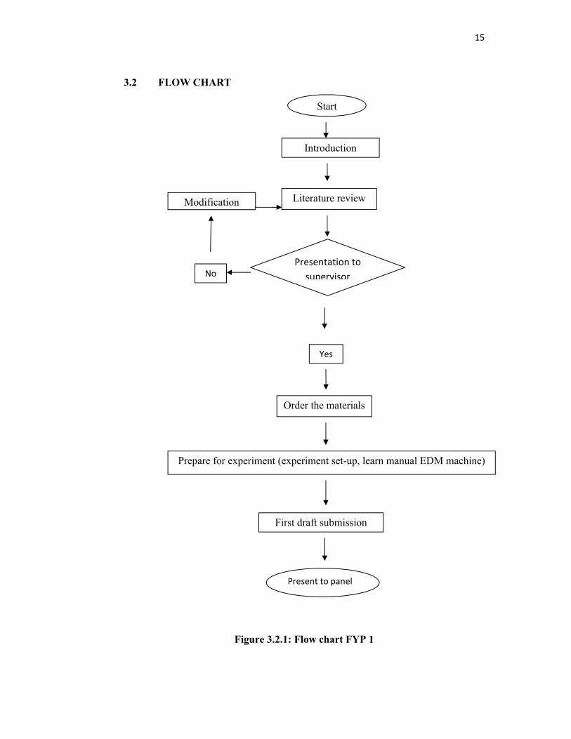
3.2 FLOW CHART
Figure 3.2.1: Flow chart FYP 1
Start
Introduction
Modification Literature review
Presentation to supervisorNo
Yes
Order the materials
Prepare for experiment (experiment set-up, learn manual EDM machine)
First draft submission
Present to panel
16
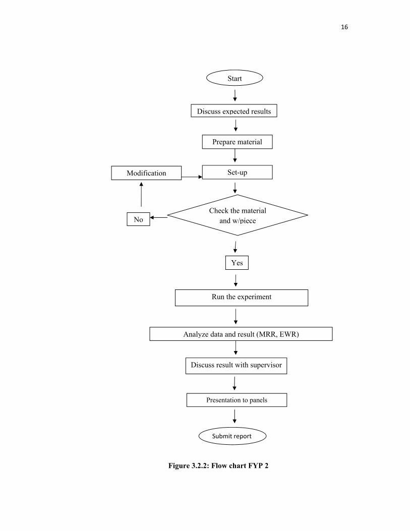
Figure 3.2.2: Flow chart FYP 2
Start
Discuss expected results
Prepare material
Set-upModification
Check the material and w/pieceNo
Yes
Run the experiment
Analyze data and result (MRR, EWR)
Discuss result with supervisor
Presentation to panels
Submit report

17
3.3 MATERIAL SELECTION
Material selection is the most important to this experiment because different
materials have different working parameters based of their properties. The right
selection of the machining material is the most important aspect to take into
consideration in processes related to the EDM. From the observation and discussion
with partner and supervisor, the electrode material that has been selected is
Aluminum, brass and cooper while the tools steels as their work pieces.
3.3.1 Tool Steels
Tool steels as work pieces are steels that are primarily used to make tools
used in manufacturing processes as well as for machining metals, woods, and
plastics. Tool steels are generally ingot-cast wrought products, and must be able to
withstand high specific loads as well as be stable at elevated temperatures. The tool
steels that used in this experiment is high speed tools steel (XW42 Tool Steel). High-
Speed Tool Steels: High-speed alloys include all molybdenum (M1 to M52) and
tungsten (T1 to T15) class alloys. High-speed tools steels can be hardened to 62-67
HRC and can maintain this hardness in service temperatures as high as 540 °C
(1004°F), making them very useful in high-speed machinery. Typical applications
are end mills, drills, lathe tools, planar tools, punches, reamers, routers, taps, saws,
broaches, chasers, and hobs.
3.3.2 Electrodes
The important factors in selecting aluminum, brass and cooper are their high
strength-to-weight ratio, resistance to corrosion by many chemicals, high thermal and
electrical conductivity, non-toxicity, reflectivity, appearance and ease of formability
and of machinability; they are also nonmagnetic.
The important factors in selecting aluminum (Al) and its alloys are their high
strength-to-weight ratio, resistance to corrosion by many chemicals, high thermal and
electrical conductivity, nontoxicity, reflectivity, appearance and ease of formability
18
and of machinability; they are also nonmagnetic. The principal uses of aluminum and
its alloys, in decreasing order of consumption, are containers and packaging
(aluminum cans and foil), building and other types of construction,
transportation(aircraft, automobiles and aerospace), electrical applications (as an
economical and nonmagnetic electrical conductor) and portable tools.
Brass is any alloy of copper and zinc; the proportions of zinc and copper can
be varied to create a range of brasses with varying properties. In comparison, bronze
is principally an alloy of copper and tin. Despite this distinction, some types of
brasses are called bronzes. Brass is a substitutional alloy. It is used for decoration for
its bright gold-like appearance; for applications where low friction is required such
as locks, gears, bearings, ammunition, and valves; for plumbing and electrical
applications; and extensively in musical instruments such as horns and bells for its
acoustic properties.
Copper is a chemical element with the symbol Cu (Latin: cuprum) and atomic
number 29. It is a ductile metal with excellent electrical conductivity. Copper is
rather supple in its pure state and has a pinkish luster which is (beside gold) unusual
for metals, which are normally silvery white. It is used as a heat conductor, an
electrical conductor, as a building material and as a constituent of various metal
alloys. Copper is malleable and ductile, a good conductor of heat and, when very
pure, a good conductor of electricity. Copper is malleable and ductile, a good
conductor of heat and, when very pure, a good conductor of electricity.
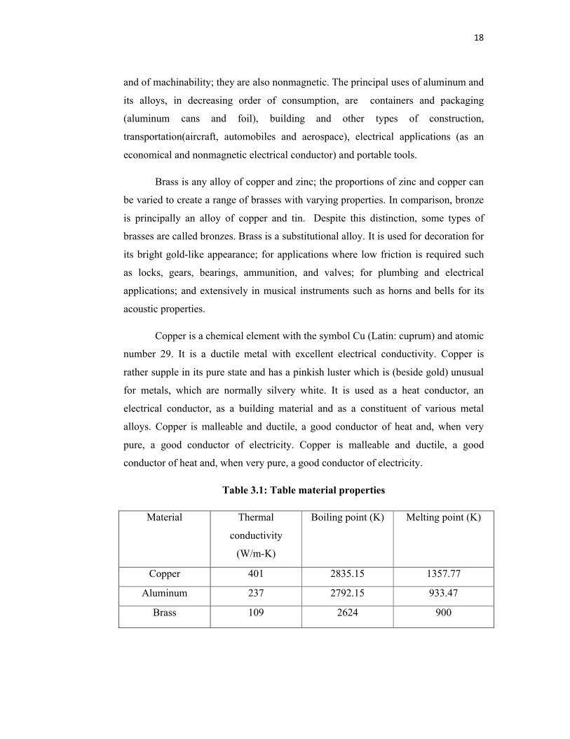
Table 3.1: Table material properties
Material Thermal
conductivity
(W/m-K)
Boiling point (K) Melting point (K)
Copper 401 2835.15 1357.77
Aluminum 237 2792.15 933.47
Brass 109 2624 900
19
3.4 MACHINE AND EQUIPMENT
The following equipments were used in this experimental works:
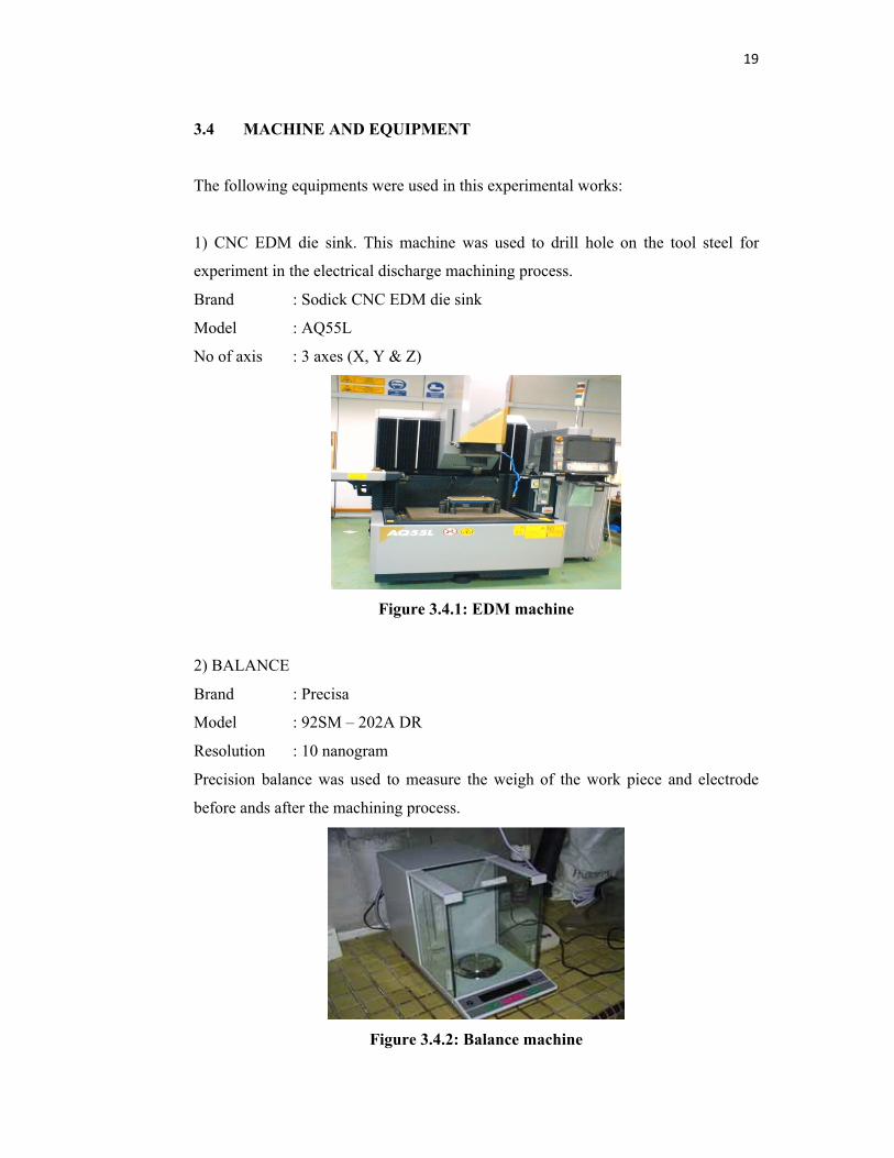
1) CNC EDM die sink. This machine was used to drill hole on the tool steel for
experiment in the electrical discharge machining process.
Brand : Sodick CNC EDM die sink
Model : AQ55L
No of axis : 3 axes (X, Y & Z)
Figure 3.4.1: EDM machine
2) BALANCE
Brand : Precisa
Model : 92SM – 202A DR
Resolution : 10 nanogram
Precision balance was used to measure the weigh of the work piece and electrode
before ands after the machining process.
Figure 3.4.2: Balance machine
20
3.5 EXPERIMENT METHOD
In machining any material using wire Electro Discharge Machine (EDM),
there are still have many problem for this machine mentioned in chapter one. In order
to investigate this study, the design of experiment will be create to solving the
parameters problem. This section also discuss about material that must be selected
for this study.
3.5.1 Experimental Set-up
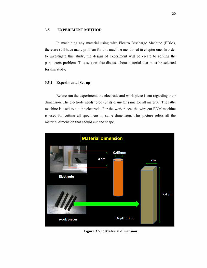
Before run the experiment, the electrode and work piece is cut regarding their
dimension. The electrode needs to be cut its diameter same for all material. The lathe
machine is used to cut the electrode. For the work piece, the wire cut EDM machine
is used for cutting all specimens in same dimension. This picture refers all the
material dimension that should cut and shape.
Figure 3.5.1: Material dimension

21
3.5.2 Experiment Procedure
The electric discharge machine, model SODICK AQ55L (die sinking type)
with servo-head (constant gap) and positive polarity for electrode (reverse polarity)
will used to conduct the experiment. Kerosene will used as dielectric fluid. These are
the procedure of this experiment:
1) Experiment will conducted with positive polarity of electrode. The electrode
aluminum is taken. The diameter of electrode is measured with a micrometer.
Make sure its dimension is according to specification.
2) An initial mass is measured with Precisa balance model 92SM – 202A DR.
Take the electrode mass value and the work piece mass value.
3) The work material (tool steel) was mounted on the T-slot table and positioned
at the desire place and clamped. The electrode was clamped on the V-block,
and its alignment was checked with the help of the try square.
4) Set the parameters of the experiment regarding table 1.1
5) A depth of cut of 1 mm was set for the machining of all work materials.
Finally, switches ‘ON’ for operating the desire discharge current values.
6) After machining operation, the electrode was taken out and weight again on
Precisa balance. Also take the mass value of work piece after machining.
7) The same experiment was repeated with other different electrode materials.
This experiment is done by 5 times. The data will take and the average data
calculated. This is to make sure the data more accurate.

22
3.5.3 Machining Parameters
The parameters that are involved in this study are shown in Table 3.2
Table 3.2: Parameters table
Electrode
material
Voltage
(V)
Current
(A)
Depth of cut
(mm)
Dielectric
fluid
Aluminum 3 0.2 1 kerosene
Brass 3 0.2 1 kerosene
Cooper 3 0.2 1 kerosene
3.6 DATA COLLECTION
The data that will be taken is:
1) Machining time, t
2) Mass of work piece before and after, g
3) Work pieces removal rate (WRR), g
4) Electrode wear weight (EWR), g
3.6.1 Analyzed Method
The present work highlights the development of mathematical solution to
calculate the EDM machining parameters such as: mass of electrode, pulse duration
and voltage on the metal removal rate, wear ratio and surface roughness. This work
has been established based on the mathematical equation (3.0). The MRR of the
work piece was measured by dividing the weight of work piece before and after
machining (found by weighing method using balance) against the machining time
that was achieved. After completion of each machining process, the work piece was
blown by compressed air using air gun to ensure no debris and dielectrics were
present. A precise balance (Precisa 92SM – 202A DR) was used to measure the
23
weight of the work piece required. Similar procedure for measuring the weight of
work piece was used to determine the weight of the electrode before and after
machining. The equation (3.1) will used for determine the EWR value:
MRR (g/min) = WRR/T ………………………………equation 3.0
EWR (%) = [EWW/WRW] ×100 …………………….…equation 3.1
The higher material removal rate in the EDM machine, the better is the machining
performance. While, the lower electrode wear ratio in the EDM machine is the better
and accurate performance characteristic. Due to the result, the best electrode material
for EDM machining process can be determined.
3.7 SUMMARY
The electric discharge machine (EDM) process experiment has been done
under experimental set up and procedure. Graph is used to observe tool wear growth
after each experiment. Then from the graph we can determine the best selection and
proper electrode. Afterwards, the results were compared at the same material
parameters from journal. The results obtained are following graph patterns if
compared with the literature study. These results would further being interpret in
Chapter 4- Results and Discussion.
24
CHAPTER 4
RESULTS AND DISCUSSIONS
4.1 INTRODUCTION
Chapter four is generally discuss the results obtained throughout the
experimental research analysis on the material removal rate (MRR) and electrode
wear ratio (EWR) after a period of machining process.
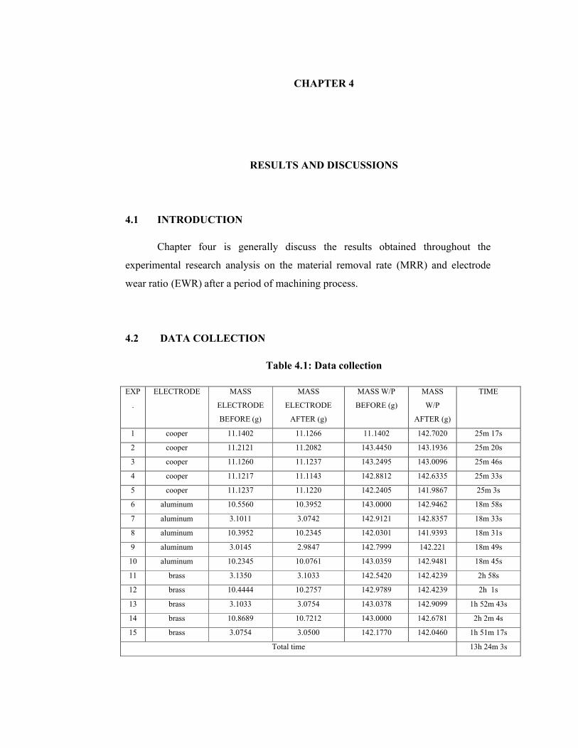
4.2 DATA COLLECTION
Table 4.1: Data collection
EXP
.
ELECTRODE MASS
ELECTRODE
BEFORE (g)
MASS
ELECTRODE
AFTER (g)
MASS W/P
BEFORE (g)
MASS
W/P
AFTER (g)
TIME
1 cooper 11.1402 11.1266 11.1402 142.7020 25m 17s
2 cooper 11.2121 11.2082 143.4450 143.1936 25m 20s
3 cooper 11.1260 11.1237 143.2495 143.0096 25m 46s
4 cooper 11.1217 11.1143 142.8812 142.6335 25m 33s
5 cooper 11.1237 11.1220 142.2405 141.9867 25m 3s
6 aluminum 10.5560 10.3952 143.0000 142.9462 18m 58s
7 aluminum 3.1011 3.0742 142.9121 142.8357 18m 33s
8 aluminum 10.3952 10.2345 142.0301 141.9393 18m 31s
9 aluminum 3.0145 2.9847 142.7999 142.221 18m 49s
10 aluminum 10.2345 10.0761 143.0359 142.9481 18m 45s
11 brass 3.1350 3.1033 142.5420 142.4239 2h 58s
12 brass 10.4444 10.2757 142.9789 142.4239 2h 1s
13 brass 3.1033 3.0754 143.0378 142.9099 1h 52m 43s
14 brass 10.8689 10.7212 143.0000 142.6781 2h 2m 4s
15 brass 3.0754 3.0500 142.1770 142.0460 1h 51m 17s
Total time 13h 24m 3s
25
From table 4.1 we can see the total number of experiment and its data result.
Overall for experiment, the total time is taken to finish the machining is 13 hours 24
minutes and 3 second. This time is just the time of machining process and not
including the time set-up for the experiment. This experiment looks fairly suitable
for the limits of scope project due to the lack of time. In other words, more
experiment can be done if there is no limited time and more accurate result can be
obtained. But, this experiment is quite accurate because the experiment had done five
times. Hence, the data from the table 4.1 can be used and analyze. The experiment is
done with three electrode material which is brass, copper and aluminum. Every
electrode is running experiment by five times. Means every electrode done
machining a work piece (tool steel) and overalls the number of electrodes and tool
steels is 15 each. If we think again, more time are spend and waste on set up the
material than machining because every experiment needs another electrode and work
piece. But finally, the experiment done successfully and the data have been collected.
The data collections that are taken are the mass of electrode before and after, mass of
work piece before and after and time taken of every experiment. Roughly, from table
4.1 we can see the time taken for the brass material electrode is more compare with
other electrode materials. The machining time is more for electrode brass followed
by copper and brass. From the table 4.1 also we can easily find the less mass of
electrode material which aluminum. Aluminum is less in weight due to its properties
followed by brass and copper. But, this only the rough data that cannot be make as
conclusion. So, this data need to analyzed first in order to meet the objective of this
project.
4.3 ANALYSIS OF MATERIAL REMOVAL RATE (MRR)
There are many factor need to be consider during operating the machine to
make sure the results produce are in good condition and increase productivity. The
most important factor in making the production run faster is the time taken for
machining product. The time taken for machining can be express in term of material
removal rate (MRR). Material removal rate (MRR) is a value of time that calculated
to determine the rate of production in industries.
26
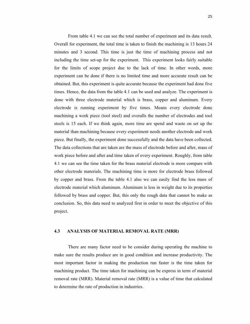
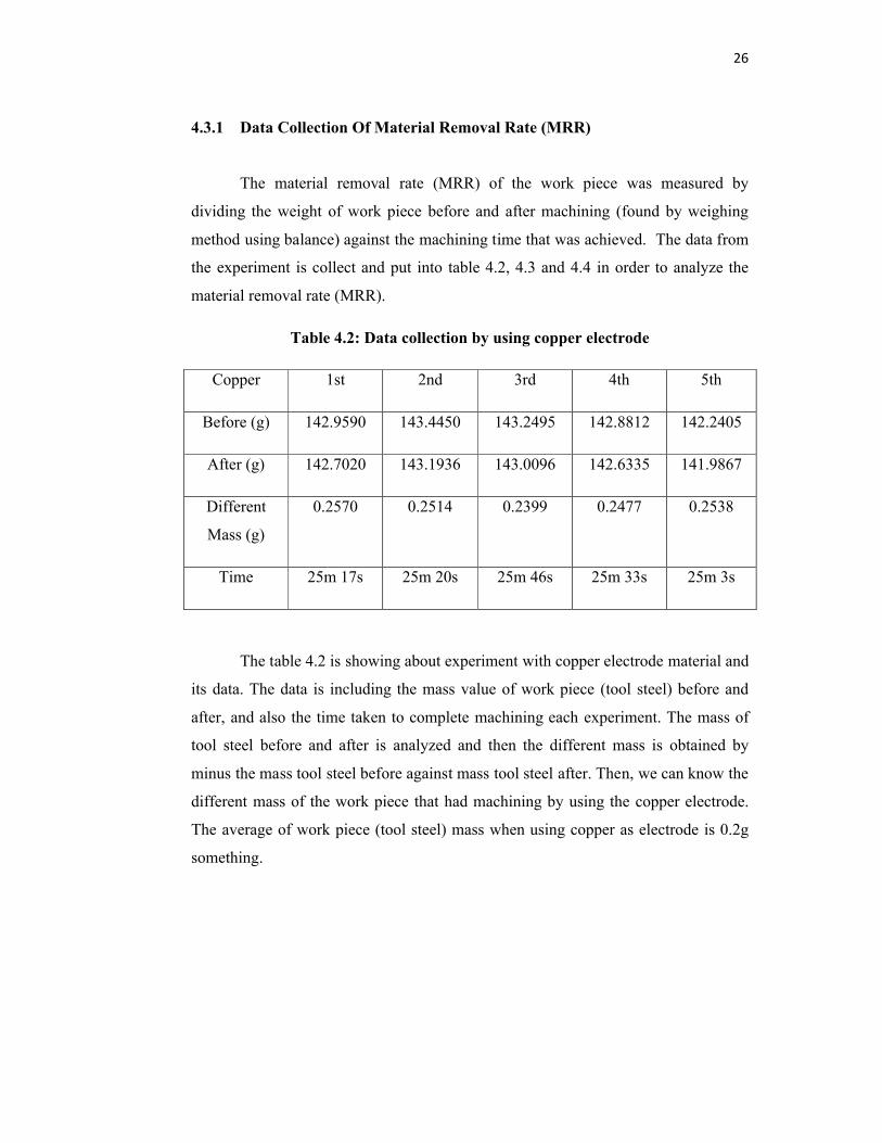
4.3.1 Data Collection Of Material Removal Rate (MRR)
The material removal rate (MRR) of the work piece was measured by
dividing the weight of work piece before and after machining (found by weighing
method using balance) against the machining time that was achieved. The data from
the experiment is collect and put into table 4.2, 4.3 and 4.4 in order to analyze the
material removal rate (MRR).
Table 4.2: Data collection by using copper electrode
Copper 1st 2nd 3rd 4th 5th
Before (g) 142.9590 143.4450 143.2495 142.8812 142.2405
After (g) 142.7020 143.1936 143.0096 142.6335 141.9867
Different
Mass (g)
0.2570 0.2514 0.2399 0.2477 0.2538
Time 25m 17s 25m 20s 25m 46s 25m 33s 25m 3s
The table 4.2 is showing about experiment with copper electrode material and
its data. The data is including the mass value of work piece (tool steel) before and
after, and also the time taken to complete machining each experiment. The mass of
tool steel before and after is analyzed and then the different mass is obtained by
minus the mass tool steel before against mass tool steel after. Then, we can know the
different mass of the work piece that had machining by using the copper electrode.
The average of work piece (tool steel) mass when using copper as electrode is 0.2g
something.
27
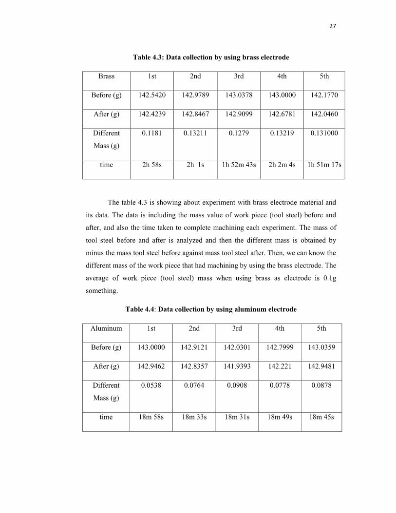
Table 4.3: Data collection by using brass electrode
Brass 1st 2nd 3rd 4th 5th
Before (g) 142.5420 142.9789 143.0378 143.0000 142.1770
After (g) 142.4239 142.8467 142.9099 142.6781 142.0460
Different
Mass (g)
0.1181 0.13211 0.1279 0.13219 0.131000
time 2h 58s 2h 1s 1h 52m 43s 2h 2m 4s 1h 51m 17s
The table 4.3 is showing about experiment with brass electrode material and
its data. The data is including the mass value of work piece (tool steel) before and
after, and also the time taken to complete machining each experiment. The mass of
tool steel before and after is analyzed and then the different mass is obtained by
minus the mass tool steel before against mass tool steel after. Then, we can know the
different mass of the work piece that had machining by using the brass electrode. The
average of work piece (tool steel) mass when using brass as electrode is 0.1g
something.
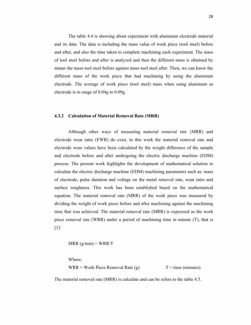
Table 4.4: Data collection by using aluminum electrode
Aluminum 1st 2nd 3rd 4th 5th
Before (g) 143.0000 142.9121 142.0301 142.7999 143.0359
After (g) 142.9462 142.8357 141.9393 142.221 142.9481
Different
Mass (g)
0.0538 0.0764 0.0908 0.0778 0.0878
time 18m 58s 18m 33s 18m 31s 18m 49s 18m 45s
28
The table 4.4 is showing about experiment with aluminum electrode material
and its data. The data is including the mass value of work piece (tool steel) before
and after, and also the time taken to complete machining each experiment. The mass
of tool steel before and after is analyzed and then the different mass is obtained by
minus the mass tool steel before against mass tool steel after. Then, we can know the
different mass of the work piece that had machining by using the aluminum
electrode. The average of work piece (tool steel) mass when using aluminum as
electrode is in range of 0.04g to 0.09g.
4.3.2 Calculation of Material Removal Rate (MRR)
Although other ways of measuring material removal rate (MRR) and
electrode wear ratio (EWR) do exist, in this work the material removal rate and
electrode wear values have been calculated by the weight difference of the sample
and electrode before and after undergoing the electric discharge machine (EDM)
process. The present work highlights the development of mathematical solution to
calculate the electric discharge machine (EDM) machining parameters such as: mass
of electrode, pulse duration and voltage on the metal removal rate, wear ratio and
surface roughness. This work has been established based on the mathematical
equation. The material removal rate (MRR) of the work piece was measured by
dividing the weight of work piece before and after machining against the machining
time that was achieved. The material removal rate (MRR) is expressed as the work
piece removal rate (WRR) under a period of machining time in minute (T), that is
[1]:
MRR (g/min) = WRR/T
Where;
WRR = Work Piece Removal Rate (g) T = time (minutes)
The material removal rate (MRR) is calculate and can be refers to the table 4.5.

29
Table 4.5: Calculation for MRR
Electrode 1st 2nd 3rd 4th 5th Average
MRR
(g/min)
Cooper 0.01021 0.00998 0.00942 0.00978 0.01003 0.00988
Brass 0.000978 0.00110 0.001137 0.00108 0.001178 0.00109
Aluminum 0.00289 0.00417 0.00495 0.00421 0.00475 0.00419
The material removal rate (MRR) that calculated can be seeing in the table
4.5. Each machining using the selected electrode has their value of material removal
rate (MRR) for the five experiments. From that table also we can also calculate the
average of material removal rate (MRR) each machining using different electrode
material. With that value, we can know the total average of material removal rate
(MRR) if we using the selected electrode material in the machining process. By the
way, the machining using copper material as an electrode give the highest average of
material removal rate (MRR), followed by aluminum and brass.
4.3.3 Graff For Material Removal Rate (MRR)
Regarding to the table 4.5, the graph for the material removal rate (MRR) can
be plot. The value of all five experiments using selected electrodes material is
transfer into graph to make the analyzed more clearly and easy. Figure 4.1 show
about the material removal rate (MRR) when machining of three electrode material;
brass, copper and aluminum. By this graph also we can see the highest of material
removal rate (MRR) when doing machining using the copper as an electrode material
compared to others electrode material. These mean every experiment or machining
process that using copper material as electrode will give the higher material removal
rate (MRR) compared to brass and aluminum electrode. The graph from figure 4.1
has proved.

30
Figure 4.1: Graph of MRR
Figure 4.2: Graph of average MRR
Figure 4.2 show the average of material removal rate (MRR) graph after the
machining process of tool steel work piece using different electrode materials. From
this graph it shows that machining electric discharge machine (EDM) using electrode
material of copper give higher average material removal rate (MRR) than using
electrode brass or aluminum. From is graph also, we can determine the best electrode
g/min
No of experiment
Copper Brass Aluminum
g/ min
31
for machining electric discharge machine (EDM) is copper. These prove from the
higher value average of material removal rate (MRR) from graph from figure 4.1.
For material removal rate (MRR) in machining process electric discharge machine
(EDM) the proper selection for electrode material is copper. The next choice should
be aluminum due to fairly good value material removal rate (MRR). But the brass
electrode showed very poor value of material removal rate (MRR) compare to others
electrode material.
4.4 ANALYSIS OF ELECTRODE WEAR RATIO (EWR)
Electrode wear imposes high costs on manufacturers to substitute the eroded
complicated electrodes by new ones for die making. In order to increase the
machining efficiency, erosion of the work piece must be maximized and that of the
electrode minimized in EDM process. Therefore, studying the electrode wear and
related significant factors would be effective to enhance the machining productivity
and process reliability. Furthermore, in electric discharge machine (EDM), improper
selection of material as electrode when machining process is running will decrease
the accuracy of the product because influence of the electrode wear ratio (EWR)
characteristic. The wear ratio defined as the volume of metal lost from the tool
divided by the volume of metal removed from the work material, varies with the tool
and work materials used. If the rate of tool wear is high means that the material is
easy to wear and not good for machining performance.
4.4.1 Data Collection Of Electrode Wear Ratio (EWR)
Electrode wear occurs during electric discharge machine (EDM) process
leading to a lack of machining accuracy in the geometry of work piece. In industries
or engineering, electrode wear also known as electrode wear ratio (EWR). Due to
important of this characteristic against the machining process, the analyzed for
optimize performance is necessary.
32
4.4.2 The Formula Of Electrode Wear Ratio (EWR)
Therefore, studying the electrode wear and related significant factors would
be effective to enhance the machining productivity and process reliability. The
electrode wear ratio (EWR) is define by the ratio of the electrode wear weight
(EWW) to the work piece removal weight (WRW) and usually expressed as a
percentage, that is: [2]
EWR (%) = [EWW/WRW] ×100
Where;
EWW = Electrode Wear Weight
WRW = Work Piece Removal Weight
4.4.3 Calculate Electrode Wear Ratio (EWR)
In this paper, the data from the experiment is collect and put into table 4.6,
4.7 and 4.8 in order to analyze the electrode wear ratio (EWR). And then, the
calculation of the electrode wear ratio (EWR) has calculated also and can be refers to
the table 4.6.1, 4.7.1, 4.8.1.
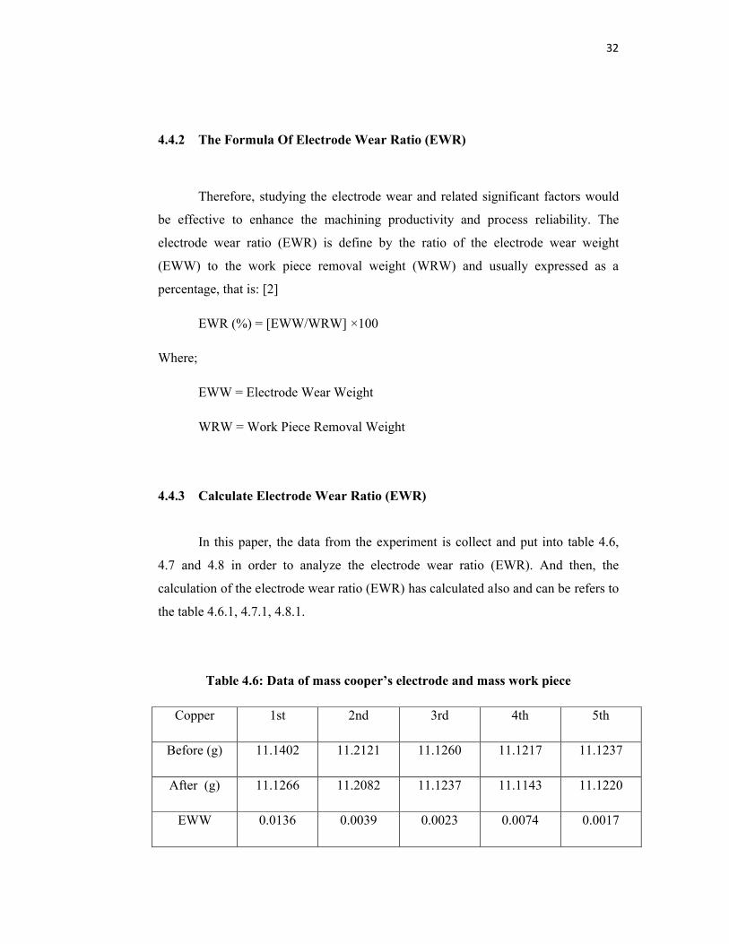
Table 4.6: Data of mass cooper’s electrode and mass work piece
Copper 1st 2nd 3rd 4th 5th
Before (g) 11.1402 11.2121 11.1260 11.1217 11.1237
After (g) 11.1266 11.2082 11.1237 11.1143 11.1220
EWW 0.0136 0.0039 0.0023 0.0074 0.0017
33
Work Piece 1st 2nd 3rd 4th 5th
Before (g) 142.9590 142.0000 143.2495 142.677 142.2405
After (g) 142.7020 141.7556 143.0096 142.427 141.9867
WRW 0.257 0.2444 0.2399 0.2499 0.2538
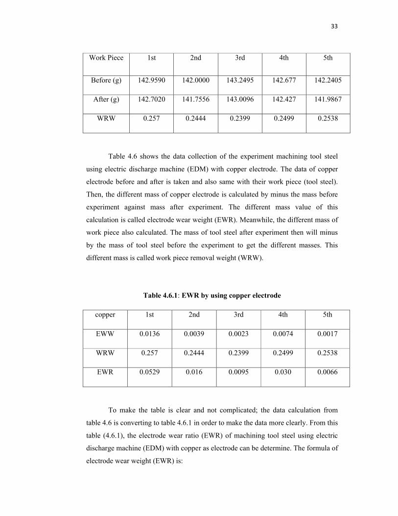
Table 4.6 shows the data collection of the experiment machining tool steel
using electric discharge machine (EDM) with copper electrode. The data of copper
electrode before and after is taken and also same with their work piece (tool steel).
Then, the different mass of copper electrode is calculated by minus the mass before
experiment against mass after experiment. The different mass value of this
calculation is called electrode wear weight (EWR). Meanwhile, the different mass of
work piece also calculated. The mass of tool steel after experiment then will minus
by the mass of tool steel before the experiment to get the different masses. This
different mass is called work piece removal weight (WRW).
Table 4.6.1: EWR by using copper electrode
copper 1st 2nd 3rd 4th 5th
EWW 0.0136 0.0039 0.0023 0.0074 0.0017
WRW 0.257 0.2444 0.2399 0.2499 0.2538
EWR 0.0529 0.016 0.0095 0.030 0.0066
To make the table is clear and not complicated; the data calculation from
table 4.6 is converting to table 4.6.1 in order to make the data more clearly. From this
table (4.6.1), the electrode wear ratio (EWR) of machining tool steel using electric
discharge machine (EDM) with copper as electrode can be determine. The formula of
electrode wear weight (EWR) is:
34
EWR = [EWW/WRW]
Where;
EWW = Electrode Wear Weight
WRW = Work Piece Removal Weight
The electrode wear ratio (EWR) can be obtained by divide the value of electrode
wear weight (EWW) against the value of work piece removal weight (WRW). We
also use the same method to calculated electrode wear ratio (EWR) in every
experiment. Means, each experiment from 1st to 5th have its own value of electrode
wear ratio (EWR). The value of the electrode wear ratio (EWR) when machining
electric discharge machine (EDM) using copper electrode now can be determine. All
the value of electrode wear ratio (EWR). All the (EWR) value then can be analyze
and discuss. The value of the electrode wear ratio (EWR) had been kept in and get
from the table 4.6.1.
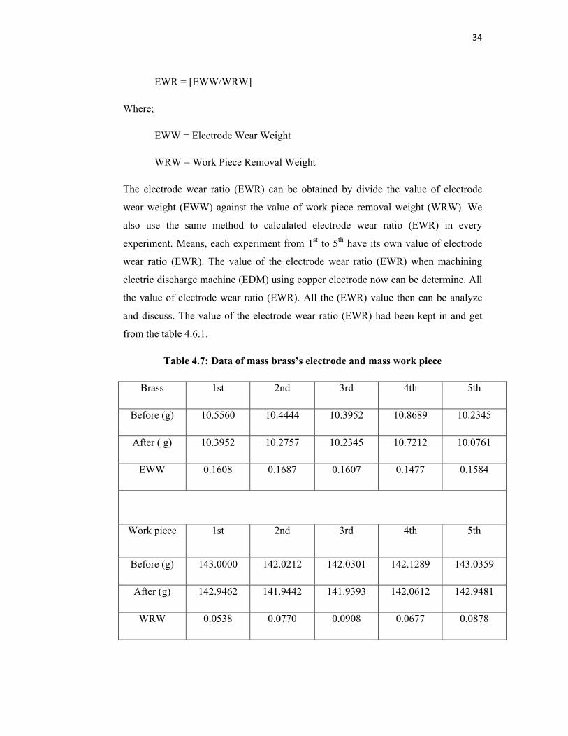
Table 4.7: Data of mass brass’s electrode and mass work piece
Brass 1st 2nd 3rd 4th 5th
Before (g) 10.5560 10.4444 10.3952 10.8689 10.2345
After ( g) 10.3952 10.2757 10.2345 10.7212 10.0761
EWW 0.1608 0.1687 0.1607 0.1477 0.1584
Work piece 1st 2nd 3rd 4th 5th
Before (g) 143.0000 142.0212 142.0301 142.1289 143.0359
After (g) 142.9462 141.9442 141.9393 142.0612 142.9481
WRW 0.0538 0.0770 0.0908 0.0677 0.0878

35
Table 4.7 shows the data collection of the experiment machining tool steel
using electric discharge machine (EDM) with brass electrode. The data of copper
electrode before and after is taken and also same with their work piece (tool steel).
Then, the different mass of brass electrode is calculated by minus the mass before
experiment against mass after experiment. The different mass value of this
calculation is called electrode wear weight (EWR). Meanwhile, the different mass of
work piece also calculated. The mass of tool steel after experiment then will minus
by the mass of tool steel before the experiment to get the different masses. This
different mass is called work piece removal weight (WRW).
Table 4.7.1: EWR by using brass electrode
Brass 1st 2nd 3rd 4th 5th
EWW 0.1608 0.1687 0.1607 0.1477 0.1584
WRW 0.0538 0.0770 0.0908 0.0677 0.0878
EWR 2.988 2.1910 1.769 2.1830 1.804
To make the table is clear and not complicated; the data calculation from
table 4.7 is converting to table 4.7.1 in order to make the data more clearly. From this
table (4.7.1), the electrode wear ratio (EWR) of machining tool steel using electric
discharge machine (EDM) with copper as electrode can be determine. The formula of
electrode wear weight (EWR) is:
EWR = [EWW/WRW]
Where;
EWW = Electrode Wear Weight
WRW = Work Piece Removal Weight
The electrode wear ratio (EWR) can be obtained by divide the value of electrode
wear weight (EWW) against the value of work piece removal weight (WRW). We
also use the same method to calculated electrode wear ratio (EWR) in every

36
experiment. Means, each experiment from 1st to 5th have its own value of electrode
wear ratio (EWR). All the (EWR) value then can be analyze and discuss. The value
of the electrode wear ratio (EWR) when machining electric discharge machine
(EDM) using brass electrode now can be determine. All the value of electrode wear
ratio (EWR) had been kept in and get from the table 4.7.1.
Table 4.8: Data of mass aluminum’s electrode and mass work piece
Aluminum 1st 2nd 3rd 4th 5th
Before (g) 3.1350 3.1011 3.1033 3.0145 3.0754
After (g) 3.1033 3.0742 3.0754 2.9847 3.0500
EWW 0.0317 0.0269 0.0279 0.0298 0.0254
Work piece 1st 2nd 3rd 4th 5th
Before (g) 142.5420 142.6664 143.0378 143.6442 142.1770
After (g) 142.4239 142.5497 142.9099 143.5092 142.0460
WRW 0.1181 0.1167 0.1279 0.1350 0.131
Table 4.8 shows the data collection of the experiment machining tool steel
using electric discharge machine (EDM) with brass electrode. The data of aluminum
electrode before and after is taken and also same with their work piece (tool steel).
Then, the different mass of brass electrode is calculated by minus the mass before
experiment against mass after experiment. The different mass value of this
calculation is called electrode wear weight (EWR). Meanwhile, the different mass of
work piece also calculated. The mass of tool steel after experiment then will minus
by the mass of tool steel before the experiment to get the different masses. This
different mass is called work piece removal weight (WRW).

37
Table 4.8.1: EWR by using aluminum electrode
Aluminum 1st 2nd 3rd 4th 5th
EWW 0.0317 0.0269 0.0279 0.0298 0.0254
WRW 0.1181 0.1167 0.1279 0.1350 0.131
EWR 0.2684 0.2310 0.2181 0.2210 0.1938
Same technique like before, to make the table is clear and not complicated;
the data calculation from table 4.7 is converting to table 4.7.1 in order to make the
data more clearly. From this table (4.7.1), the electrode wear ratio (EWR) of
machining tool steel using electric discharge machine (EDM) with copper as
electrode can be determine. The formula of electrode wear weight (EWR) is:
EWR = [EWW/WRW]
Where;
EWW = Electrode Wear Weight
WRW = Work Piece Removal Weight
The electrode wear ratio (EWR) can be obtained by divide the value of electrode
wear weight (EWW) against the value of work piece removal weight (WRW). We
also use the same method to calculated electrode wear ratio (EWR) in every
experiment. Means, each experiment from 1st to 5th have its own value of electrode
wear ratio (EWR). All the (EWR) value then can be analyze and discuss. The value
of the electrode wear ratio (EWR) when machining electric discharge machine
(EDM) using aluminum electrode now can be determine. All the value of electrode
wear ratio (EWR) had been kept in and get from the table 4.7.1.
38
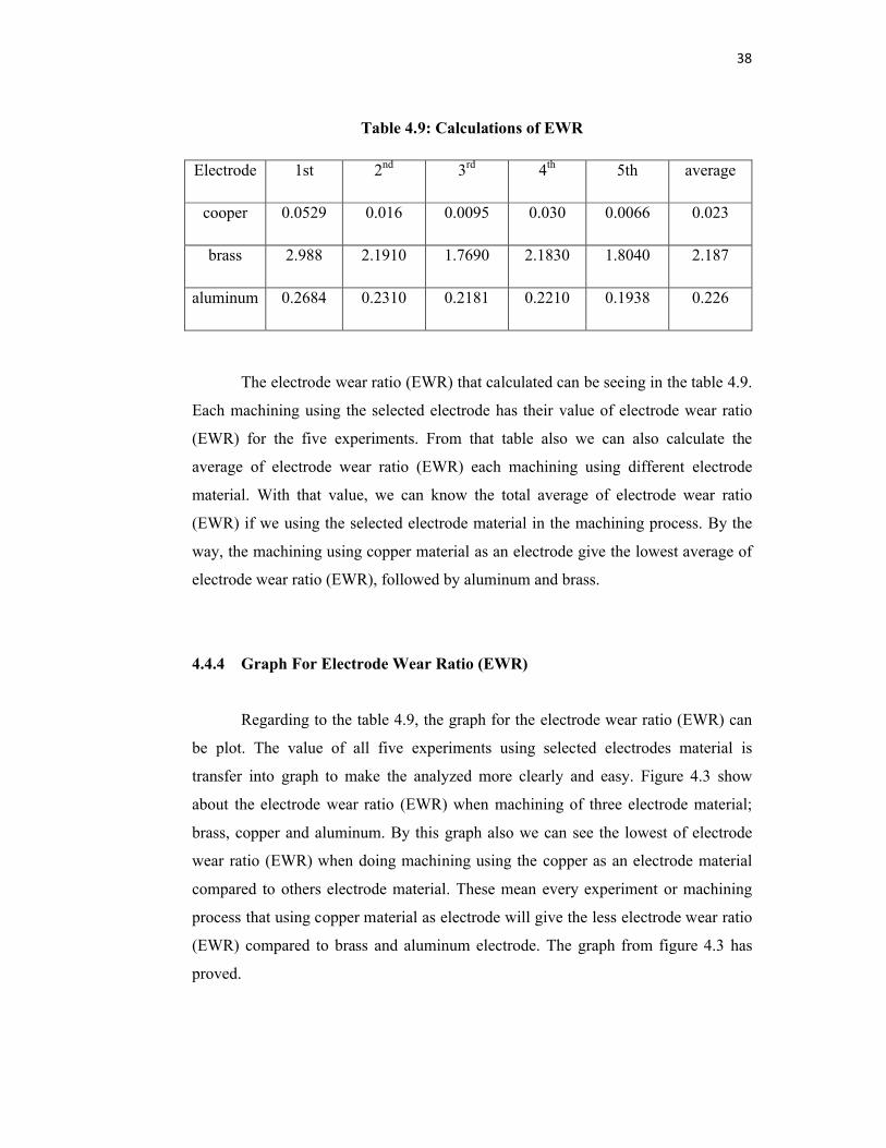
Table 4.9: Calculations of EWR
Electrode 1st 2nd 3rd 4th 5th average
cooper 0.0529 0.016 0.0095 0.030 0.0066 0.023
brass 2.988 2.1910 1.7690 2.1830 1.8040 2.187
aluminum 0.2684 0.2310 0.2181 0.2210 0.1938 0.226
The electrode wear ratio (EWR) that calculated can be seeing in the table 4.9.
Each machining using the selected electrode has their value of electrode wear ratio
(EWR) for the five experiments. From that table also we can also calculate the
average of electrode wear ratio (EWR) each machining using different electrode
material. With that value, we can know the total average of electrode wear ratio
(EWR) if we using the selected electrode material in the machining process. By the
way, the machining using copper material as an electrode give the lowest average of
electrode wear ratio (EWR), followed by aluminum and brass.
4.4.4 Graph For Electrode Wear Ratio (EWR)
Regarding to the table 4.9, the graph for the electrode wear ratio (EWR) can
be plot. The value of all five experiments using selected electrodes material is
transfer into graph to make the analyzed more clearly and easy. Figure 4.3 show
about the electrode wear ratio (EWR) when machining of three electrode material;
brass, copper and aluminum. By this graph also we can see the lowest of electrode
wear ratio (EWR) when doing machining using the copper as an electrode material
compared to others electrode material. These mean every experiment or machining
process that using copper material as electrode will give the less electrode wear ratio
(EWR) compared to brass and aluminum electrode. The graph from figure 4.3 has
proved.
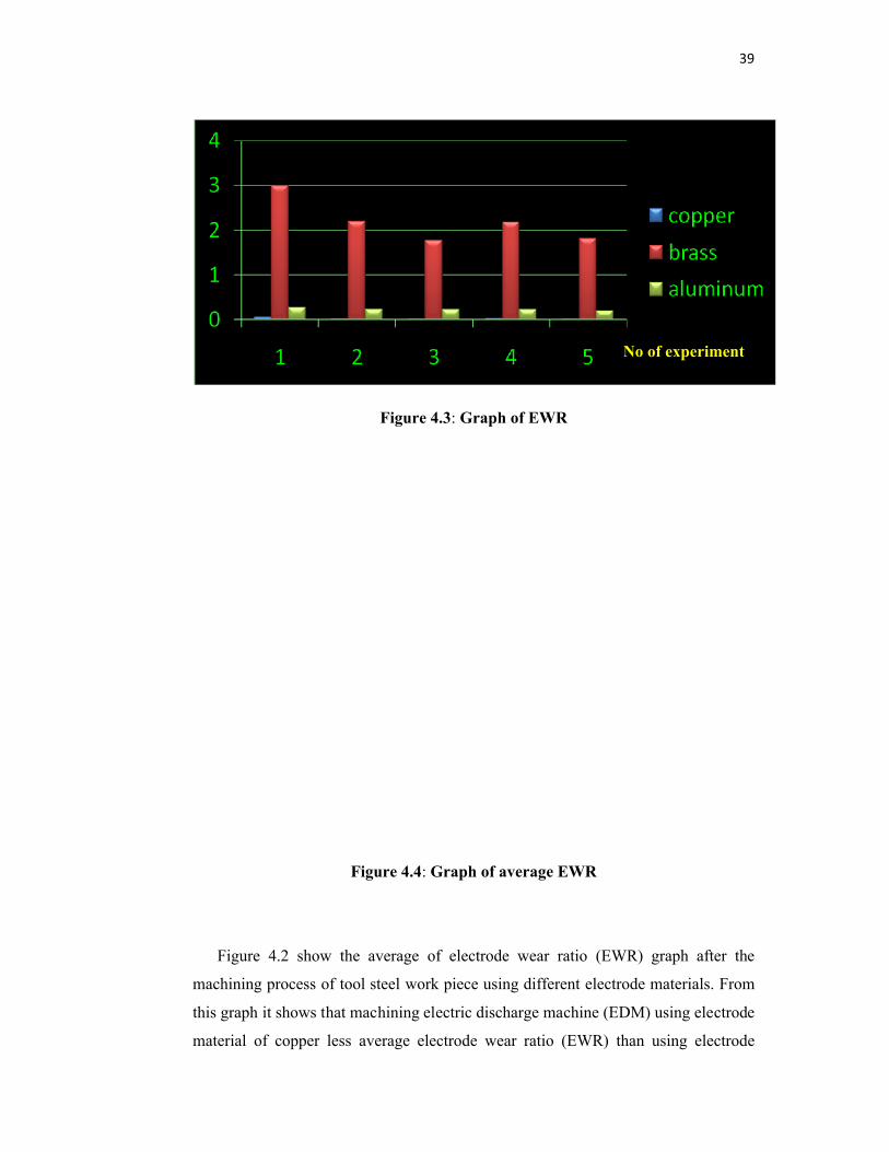
39
Figure 4.3: Graph of EWR
Figure 4.4: Graph of average EWR
Figure 4.2 show the average of electrode wear ratio (EWR) graph after the
machining process of tool steel work piece using different electrode materials. From
this graph it shows that machining electric discharge machine (EDM) using electrode
material of copper less average electrode wear ratio (EWR) than using electrode
No of experiment
40
brass or aluminum. From is graph also, we can determine the best electrode for
machining in electric discharge machine (EDM) is copper. These prove from the less
value average of electrode wear ratio (EWR) from graph from figure 4.1. For
electrode wear ratio (EWR) in machining process electric discharge machine (EDM)
the proper selection for electrode material is copper. The next choice should be
aluminum due to average value electrode wear ratio (EWR). But the brass electrode
showed very high value of electrode wear ratio (EWR) compare to others electrode
material.
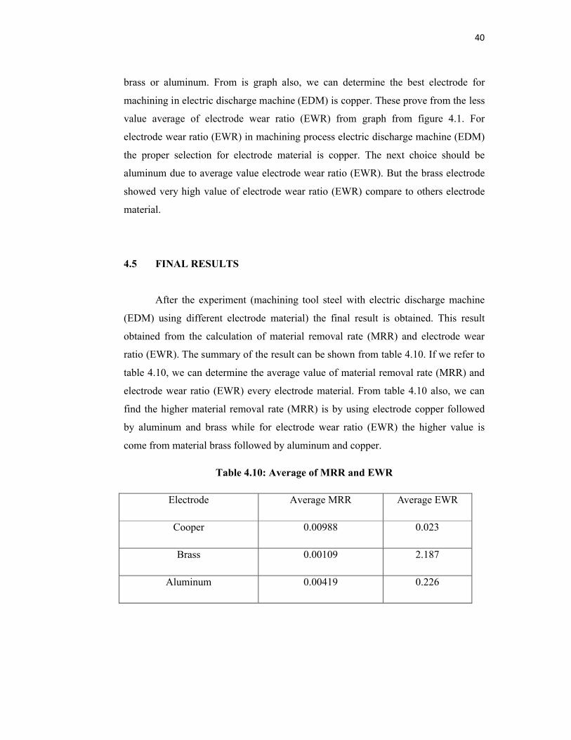
4.5 FINAL RESULTS
After the experiment (machining tool steel with electric discharge machine
(EDM) using different electrode material) the final result is obtained. This result
obtained from the calculation of material removal rate (MRR) and electrode wear
ratio (EWR). The summary of the result can be shown from table 4.10. If we refer to
table 4.10, we can determine the average value of material removal rate (MRR) and
electrode wear ratio (EWR) every electrode material. From table 4.10 also, we can
find the higher material removal rate (MRR) is by using electrode copper followed
by aluminum and brass while for electrode wear ratio (EWR) the higher value is
come from material brass followed by aluminum and copper.
Table 4.10: Average of MRR and EWR
Electrode Average MRR Average EWR
Cooper 0.00988 0.023
Brass 0.00109 2.187
Aluminum 0.00419 0.226

41
4.5.1 Result Comparison With Journals
To make sure the result of the experiment is right; compare result with
another relevant journal is a great method to do so. The result that obtain should be
compare to some journal in order to know whether that experiment we run is correct
or not. In this case study, the journal that wants to compare must be including
material removal rate (MRR), electrode wear ratio (EWR) and the same materials
used as electrode in their experiment.
After a few researches, the journal that wants to compare is from Shankar
Singh, S. Maheshwari and P.C. Pandey title; some investigations into the electric
discharge machining of hardened tool steel using different electrode materials. From
this journal, their result about material removal rate (MRR) can be seeing from the
figure 4.5.
Figure 4.5: MRR result from journal

42
The figure 4.5 tell us about the result of machining work piece in electric
discharge machine (EDM) using four different electrode; which is copper, copper
tungsten, brass and aluminum. Meanwhile, the journal’s result about electrode wear
ratio (EWR) also can be seeing from the figure 4.6. The figure 4.6 tell us about the
result of machining work piece in electric discharge machine (EDM) using four
different electrode; which is copper, copper tungsten, brass and aluminum. For the
value of electrode wear ratio (EWR) in journal’s experiment can be refer in figure
4.6.
Figure 4.6: EWR result from journal
43
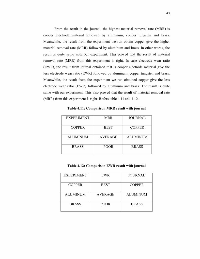
From the result in the journal, the highest material removal rate (MRR) is
cooper electrode material followed by aluminum, copper tungsten and brass.
Meanwhile, the result from the experiment we run obtain copper give the higher
material removal rate (MRR) followed by aluminum and brass. In other words, the
result is quite same with our experiment. This proved that the result of material
removal rate (MRR) from this experiment is right. In case electrode wear ratio
(EWR), the result from journal obtained that is cooper electrode material give the
less electrode wear ratio (EWR) followed by aluminum, copper tungsten and brass.
Meanwhile, the result from the experiment we run obtained copper give the less
electrode wear ratio (EWR) followed by aluminum and brass. The result is quite
same with our experiment. This also proved that the result of material removal rate
(MRR) from this experiment is right. Refers table 4.11 and 4.12.
Table 4.11: Comparison MRR result with journal
EXPERIMENT MRR JOURNAL
COPPER BEST COPPER
ALUMINUM AVERAGE ALUMINUM
BRASS POOR BRASS
Table 4.12: Comparison EWR result with journal
EXPERIMENT EWR JOURNAL
COPPER BEST COPPER
ALUMINUM AVERAGE ALUMINUM
BRASS POOR BRASS
44
4.6 DISCUSSION
4.6.1 The Theory
The selection material of electrode important because its influence most of
the machining performance in electric discharge machine (EDM). This is due to the
material’s properties itself. The properties of the material will affect the machining
characteristic like material removal rate (MRR) and electrode wear ratio (EWR) in
electric discharge machine (EDM). The properties of material including thermal
conductivity, boiling point, melting point and so on resulting differently depends on
material selection itself. In this experiment, the material that chose to do machining
is copper, brass and aluminum. The experiment’s result of these material selections
give different value of material removal rate (MRR) and electrode wear ratio (EWR)
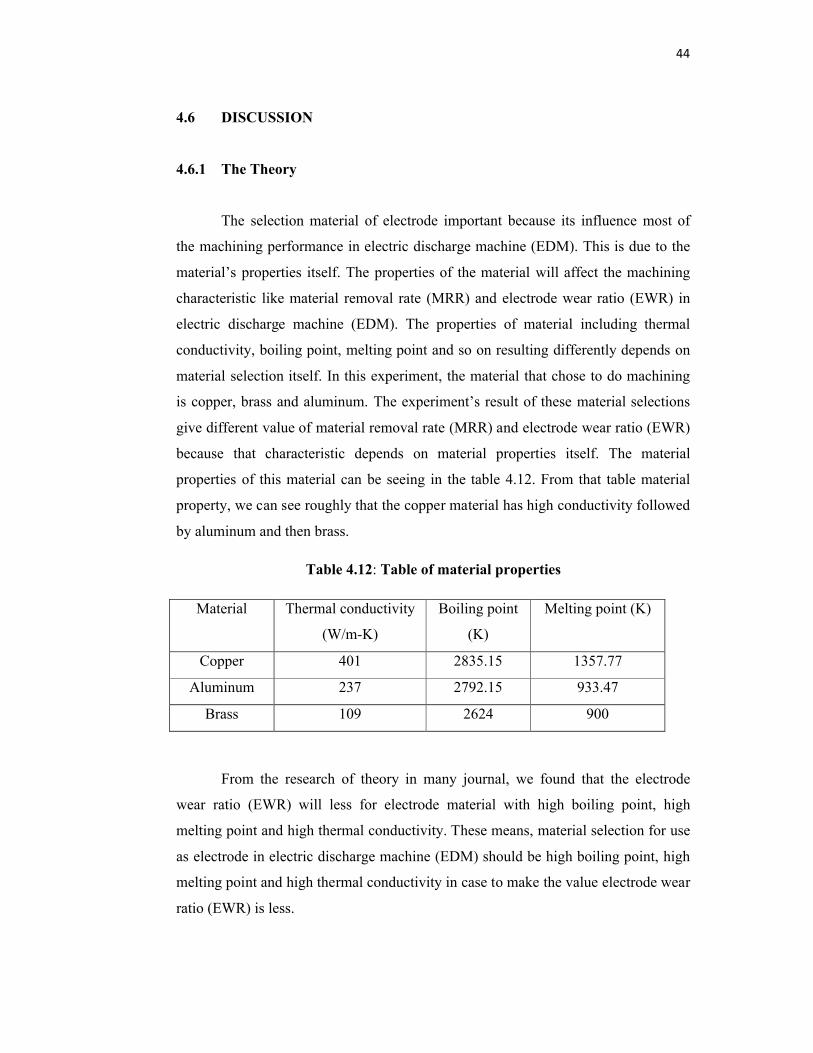
because that characteristic depends on material properties itself. The material
properties of this material can be seeing in the table 4.12. From that table material
property, we can see roughly that the copper material has high conductivity followed
by aluminum and then brass.
Table 4.12: Table of material properties
Material Thermal conductivity
(W/m-K)
Boiling point
(K)
Melting point (K)
Copper 401 2835.15 1357.77
Aluminum 237 2792.15 933.47
Brass 109 2624 900
From the research of theory in many journal, we found that the electrode
wear ratio (EWR) will less for electrode material with high boiling point, high
melting point and high thermal conductivity. These means, material selection for use
as electrode in electric discharge machine (EDM) should be high boiling point, high
melting point and high thermal conductivity in case to make the value electrode wear
ratio (EWR) is less.
45
As we know, the electrode wear ratio (EWR) of the electrode becomes small
for the electrode material with high boiling point, high melting point, and high
thermal conductivity. However, the electrode wear ratio (EWR) is inversely
proportional to the material removal rate (MRR) result. In other words, material with
high material removal rate (MRR) will have the less electrode wear ratio (EWR).
The material with high thermal conductivity must be considered to use as
electrode in machining electric discharge machine (EDM). The theory says the
material with higher thermal conductivity resulting better material removal rate
(MRR). Actually, the higher thermal conductivity of the electrode ensures a better
spark discharge energy distribution during the EDM process. When there is more
spark discharge energy, this will make the machining run effectively and fast. Hence,
the more spark discharge energy, the faster the machining can run. This will increase
material removal rate (MRR).
As we know, the increase in the material removal rate (MRR) is due to the
increase of spark discharge energy. The spark discharge energy high when the
material is more thermal conductivity. So as result, the material with high thermal
conductivity will increase material removal rate (MRR).
4.6.2 Discussion Of Material Removal Rate (MRR)
4.6.2.1 Material Removal Rate
In industries, the production rate is a part that they consider most. The
production rate is a rate or time taken to do a process in making product. If the
production rate is slow, the profit flow is also slow. But if the production rate is high,
the more profit can gain. To increase the production rate, we need to increase the
material removal rate (MRR). When the material removal rate (MRR) is higher, the
production also run faster.
46
4.6.2.2 Results And Analysis Of Material Removal Rate (MRR)
Table 4.10 shows the effect of electrode material on material removal rate
(MRR) for the tool steel work piece material. The copper electrodes achieve the best
material removal rate (MRR) with the increase in discharge current, followed by
aluminum electrode. Brass does not indicate significant increase in MRR. The
average material removal rate (MRR) of cooper is 0.00988 g/min while aluminum is
0.00419 g/min and brass is 0.00109 g/min. Copper gives the best material removal
rate (MRR) on tool steel work piece material. From the theory, the material with high
thermal conductivity will result increasing the material removal rate (MRR). As we
can see from table 4.10, the properties of all material in term conductivity; copper
give the higher conductivity compare to aluminum and brass. The spark discharge
energy also high when the material is more thermal conductivity. The increase in
material removal rate (MRR) is due to the fact that the spark discharge energy is
increased to facilitate the action of melting and vaporization, and advancing the large
impulsive force in the spark gap, there by increasing the material removal rate
(MRR). Experimental investigations have shown that material removal rate (MRR) is
dependent upon the electrode material, work material and dielectric flushing. The
material removal rate (MRR) is also controlled by the frequency of the sparks. It is
observed that low discharge currents and higher frequencies correspond to low stock
removal. Effective machining rate with brass electrode could not be achieved
because the brass has low conductivity.
4.6.3 Results And Analysis Of Electrode Wear Ratio (EWR)
4.6.3.1 Electrode Wear Ratio (EWR)
The high rate of tool wear is one of the main problems in electric discharge
machine (EDM). Actually, the wear ratio defined as the volume of metal lost from
the tool divided by the volume of metal removed from the work material, varies with
the tool and work materials used. If the rate of tool wear is high means that the
material is easy to wear and not good for machining performance. In industries, the

47
wear ratio is an important thing because it will cost the production. They are trying to
optimize this factor to make sure no waste occur and reduce the purchasing the
material with high wear.
4.6.3.2 Results And Analysis Of Electrode Wear Ratio (EWR)
Table 4.10 shows that the copper electrodes have minimal wear. Brass and
aluminum show a considerable increase in the electrode wear with the increase in the
discharge current. The theory says an electrode material with higher melting point
wears less. In other words, the electrode wear ratio (EWR) will less for electrode
material with high boiling point, high melting point and high thermal conductivity.
From the result of experiment, the copper give less electrode wear ratio followed by
aluminum and brass. The average of electrode wear ratio (EWR) for cooper is 0.023
while aluminum is 0.226 and brass is 2.187. Electrode wear is mainly due to high-
density electron impingement (electrical), thermal effect, mechanical vibrations
(shocks) generated by metal particles from the work material and imperfections in
the microstructure of electrode material.
4.6.4 Summary
Electrical discharge machining, more commonly known as EDM or spark
machining, removes electrically conductive materials by means of rapid, repetitive
spark discharges from electric pulse generators with the dielectric flowing between
the tool and the work piece. No physical cutting forces exist between the work piece
and tool. Machining with electric discharge machine (EDM) sometimes faces
problem with productivity rate and product finishing accuracy. The machining rate
will be slow and low product finishing qualities if the not use the proper machining
parameters. The most important parameters to solve this problem are electrode
selection material. To optimize, the best electrode material for machining process in
electric discharge machine (EDM) is need to determine.
48
There are many factors that influence machining process in electric discharge
machine (EDM) especially its machining characteristics. Machining characteristics
are material removal rate (MRR) and electrode wear ratio (EWR). This characteristic
mostly depends on the material properties. The material properties like thermal
conductivity, melting point and others. Moreover, it has been found from the
experimental investigation that in case of material removal rate (MRR), electrical
and thermal conductivity are the primary influencing factors. The high electrical
conductivity facilitates the sparking process and increases effective pulses which
increase material removal rate (MRR). On the other hand, higher thermal
conductivity is useful to raise the temperature of the work piece above the melting
point in a short time. These are the reasons why copper electrode material provide
higher material removal rate (MRR) in the finishing. However, the melting point has
a secondary effect on the material removal rate (MRR). It has been observed that
copper electrode material provides better material removal rate (MRR) than brass.
The reason could be the higher melting point (153.77 K) of copper compared to that
of brass (900 K).
Moreover, the electrode wear ratio (EWR) of an electrode strongly depends
on the electrical and thermal properties of the electrode material. The evaporation
point, melting point, thermal conductivity and thermal diffusivity are the important
properties that influence the electrode wear of an electrode. The basic requirement of
an electrode material is the high melting and evaporation point in addition to high
thermal conductivity. It has been found from the study that the electrode wear ratio
(EWR) is almost inversely proportional to the melting point of the electrode material.
From table 4.12 seen that for every experiment, the wear of copper electrode is the
lowest due to its highest melting point among the three electrodes. The aluminum
electrode has also good wear resistance due to its moderately high melting point and
strong spark-resisting capacity. On the other hand, the brass electrode suffers the
highest electrode wear ratio (EWR) in spite of its higher thermal and electrical
conductivity among the three electrodes.

49
4.6.4.1 Selecting Electrode
When selecting an electrode material for using in machining in electric
discharge machine (EDM), several factors must be considered, including the cost,
strength, resistance to wear, and machinability. The machinability of a material is
difficult to quantify, but can be said to posses the following characteristics:
1. Provides faster rate for production; higher material removal rate (MRR)
2. Promotes long tool life; less electrode wear ratio (EWR)
3. Easy to find, lower cost and available.
4. Results in a good surface finish; (finishing surface free from electrode that
have wear)
4.6.4.2 Optimization
1. If to optimize production and faster rate, choose electrode material with high
material removal rate (MRR).
2. The costs of production also including the tool wear. Means, if possible try to
select electrode with lowest electrode wear ratio (EWR) in order to make tool
life long.
3. Select an electrode material that minimizes overall cost.
50
CHAPTER 5
CONCLUSION
5.1 INTRODUCTION
Chapter 5 summarizes all the main research points of this project. It
concludes the crucial information and observation obtained during the project.
Especially on the machining characteristic in machining electric discharge machine
(EDM). These conclusions pay more attention at objective of project that want to
find the proper electrode for machining tool steel. In that case, the investigation on
material removal rate (MRR) and electrode wear ratio (EWR) is being done. In this
chapter also, some recommendations have made for future research of this project.
5.2 CONCLUSION
This experiment investigated the effects of machining characteristic on
electric discharge machine using different electrode materials. As conclusion, the
experiments of this paper conclude that the machining characteristics in machining
process of electric discharge machine (EDM) influence the machining performance.
The higher material removal rate (MRR) will result in better machining
performance rate. In this experiment, the higher material removal rate (MRR)
obtained is come from electrode copper that is 0.0098 g/min followed by aluminum
(0.00419g/min) and brass (0.00109 g/min).
Meanwhile, the less electrode wear ratio (EWR) will make the machining
performance better. From this experiment, the best selection electrode for electrode
wear ratio (EWR) is copper (0.023) followed by aluminum (0.026) and brass (2.187).

51
After the results obtained, the objective is excellently achieved. The best
selection of electrode in machining tool steels is copper because it has high material
removal rate (MRR) and less electrode wear ratio (EWR).
5.3 RECOMMENDATION
There are some recommendations to be considered in improving the details of
this project. More electrode materials are highly recommended to be use as electrode
for investigation its capabilities. This is crucial to see clearly the other material
machining characteristic. Other than that, the experiments also can be conducted in
different parameters. This is needed to investigate other parameters that influence
machining performance in electric discharge machine (EDM).
52
REFERENCES
[1] G.Taguchi, introduction to Quality Engineering, Asian Productivity organization, Tokyo, 1990.
[2] P.J. Ross, Taguchi technique for quality engineering, McGraw Hill, New York, 1988.
[3] E P. M. Lonardo (l), A. A. Bruzzone, Dept. of Production Engineering, University of Genoa, Effect of Flushing and Electrode Material on Die Sinking EDM, Received on January 6,1999
[4] Some investigations into the electric discharge machining of hardened tool steel using different electrode materials, Shankar Singh (a),∗, S. Maheshwari (a), P.C. Pandey (b).
(a)Division of Manufacturing Process and Automation Engineering, Netaji Subhas Institute of Technology, Dwarka, New Delhi 110075, India,
(b) Department of Mechanical and Industrial Engineering, Indian Institute of Technology Roorkee, Roorkee 247667, India
[5] Frei. C., Hirt, C., Girardin, R., Dauw, D.F., 1987, A New Approach for Contamination Measurements for EDM Dielectrics, Annals of the CIRP, 36/1:111-113.
[6] M.Kiyak, Department of Mechanical Engineering, Yildiz Technical University, 34349 Istanbul, Turkey Journal of Materials Processing Technology 191 (2007) 141–144
[7] M. Mahardika and K. Mitsui, A new method for monitoring micro-electric discharge machining processes, International Journal of Machine Tools & Manufacture (2007) doi:10.1016/j.ijmachtools.2007.08.023
[8] M. Mahardika and K. Mitsui, Total energy of discharge pulse calculation by stochastic methods, Proceeding of the International Conference of the 10th
AUN/SEED.Net Field Wise Seminar, Hanoi, Vietnam in 28th– 29th August 2007.
[9] K.H. Ho, S.T. Newman, State of the art electrical discharge machining (EDM), International Journal of Machine Tools & Manufacture 43 (2003) 1287–1300
[10] J.L Lin, C.L. Lin, the use of orthogonal array with grey relational analysis to optimize the EDM process with multiple performance characteristics, international journal of machine tools &manufacture 42(2002) 237-244, received 19 nov 2000, accepted 12 july 2001.

53
[11] An index to evaluate the wear resistance of the electrode in micro-EDM,Yao-Yang Tsai (a),∗, Takahisa Masuzawa (b)
a) Department of Mechanical Engineering, National Taiwan University, 631 Engineering building, No. 1 Sec. 4, Roosevelt Road, Taipei, Taiwan
b)Institute of Industrial Science, University of Tokyo, Tokyo, Japan
[12] C.C. Liu, Microstructure and tool electrode erosion in EDM of TiN/Si3N4 composites, Mater. Sci. Eng. J. 363 (2003) 221–227.
[13] Y.Y. Tsai, T. Masuzawa, An index to evaluate the wear resistance of the electrode in micro-EDM, J. Mater. Process. Technol. 149 (1–3) (2004) 304–309.
[14] http://vertex.berkeley.edu/Me221/mas2/html/processes/edm/index.html
i
EFFECTS OF MACHINING CHARACTERISTICS ON ELECTRIC DISCHARGE MACHINEUSING DIFFERENT ELECTRODE MATERIALS
MOHD KHAIRUL ANUAR BIN MOHD IDRIS
A report submitted in partial fulfillment of the requirements for the award of the degree of
Bachelor of Mechanical Engineering with Manufacturing
FACULTY OF MECHANICAL ENGINEERING UNIVERSITY MALAYSIA PAHANG
NOVEMBER 2008
ii
STUDENT’S DECLARATION
“I hereby declare that the work in this thesis is my own except for quotations
and summaries which have been duly acknowledged. The thesis has not been
accepted for any degree and is not concurrently submitted for award and in
candidature of other degree.”
Signature : ………………………………
Name : MOHD KHAIRUL ANUAR BIN MOHD IDRIS
ID Number : ME05052
Date : 7 NOVEMBER 2008
iii
“I hereby declare that I had read this thesis and in my opinion this thesis is
sufficient in terms of scope and quality for the purpose of Bachelor of Mechanical
Engineering with Manufacturing Engineering.”
Signature : .
Name of Supervisor : Mr. Mohamed Reza Zalani Mohamed Suffian
Date : 31st October 2008
Signature : .
Name of Panel :
Position :

iv
“To my beloved mother, father, family and someone special who gave me encouragement and support towards this study”
v
ACKNOWLEDGEMENT
بسم اهللا الرحمن الرحیم
I would like to express my gratefulness to Allah S.W.T for giving me
strength and wisdom in my research work. In preparing this thesis, I was in contact
with many people, researchers, academicians, technicians and practitioners. They all
have contributed to my understanding and valuable thoughts during my research.
First and foremost, I would like to express my special thanks to my supervisor, Mr.
Mohamed Reza Zalani Mohamed Suffian for his encouragement, guidance, ideas
which enlighten my curiosity, suggestion, advice and friendship. I am gratefully
expressing my thanks to my whole family who understand me and gave me the spirit
and continuing support to finish this study. Owing to thanks to my vocational advisor
at UMP Mechanical Laboratory, Mr. Asmizam bin Mokhtar who gives idea, guide
and support me to finish up my task. I am grateful to my fellow collogues who also
should be recognized for their moral support. Their view and tips are useful indeed,
but it is not possible to list them all in this limited space. I only can say thanks and
may God bless you…
vi
ABSTRACT
Electric discharge machining (EDM) is a non-traditional machining processes that
involved a transient spark discharges through the fluid due to the potential difference
between the electrode and the work piece. The aim of this project is to determine the
proper electrode material for machining tool steels work pieces using electrical
discharge machining (EDM). Basically, improper choose of electrode material in
EDM machine may result a few problems like the machine may cause of poor
machining performance and it will decrease the accuracy of the products. This paper
presents a fundamental study of characteristic of electrode discharge machine (EDM)
that is electrode wear ratio (EWR) and material removal rate (MRR) by using
different electrode materials in order to increase the understanding of EDM
processes. To archive this project objective, an experiment will be doing properly.
By following the method, some literature review is going to do first before preparing
the experimental set-up. Then experiment will be runs and the data of the experiment
are taken. This is to make sure the analysis can be done in order to find the best
electrode material. There are three electrodes material should be compared that are
copper, brass and aluminum. Regarding the literature review, the higher material
removal rate in the EDM machine, the better is the machining performance while the
lower electrodes wear ratio in the EDM machine is the better and accurate
performance characteristic. Thus as the expected result for this experiment, the
copper electrode material will be the best electrode among others electrode for EDM
machining process.
vii
ABSTRAK
Mesin elektrik discas atau lebih dikenali sebagai EDM ialah salah satu alternatif baru
dalam proses pemesinan dan pemotongan bahan. Teknologi EDM melibatkan
perbezaan potensi cas elektrod dalam konduktor bendalir yang seterusnya menyahcas
dan menghasilkan daya tenaga elektrik untuk memotong bahan kerja. Dewasa ini,
EDM telah diperluaskan penggunaannya dalam industri untuk menghasilkan sesuatu
produk disebabkan ketepatan simetri hasil produk, pantas, efisyen dan banyak lagi
kelebihannya. Menyedari hakikat ini, satu kajian mengenai EDM telah dirangka
untuk menyelongkar dan memastikan elektrod yang sesuai digunakan dalam EDM
untuk memotong bahan terutamanya besi. Realitinya, pemilihan elektrod yang tidak
sesuai akan mengakibatkan kesan tidak diingini seperti jangka masa proses yang
perlahan, mutu pengeluaran yang tidak bagus serta mengurangkan ketepatan dan
kualiti produk. Tesis ini berobjektifkan untuk meyelidik kesahihan kesan dan
pengaruh karekter utama pemesinan iaitu kadar pemotongan bahan (MRR) dan
nisbah hakisan elektrod (EWR) dalam misi menentukan elektrod terbaik untuk
pemotongan unsur besi. Rentetan itu, experimentasi harus dilakukan demi
menjadikan tujuan asal projek ini terlaksana. Eksperimen ini dilakukan setelah
selesai membaca serta mentelaah bahan-bahan artikel dan juga pencarian maklumat
di jalur lebar. Apabila selesai, data yang dikumpul bakal dianalisa untuk menentukan
nilai MRR dan EWR. Namun, eksperimen melibatkan pemotongan besi ini hanya
dihadkan untuk mengkaji 3 jenis elektrod sahaja iaitu kuprum, perak dan aluminium.
Merujuk hasil kajian yang lepas, lebih tinggi nilai MRR bakal mencanangkan
produktiviti yang lebih baik. Sebaliknya, semakin merosot nilai EWR pula
menjadikan mutu kerja yang semakin efisyen. Melalui informasi ini juga, ramalan
mengenai elektrod terbaik untuk pemesinan besi dengan EDM kemungkinan besar
adalah kuprum.

viii
TABLE OF CONTENTS
CHAPTER TITLE PAGE
TITLE i
SUPERVISOR DECLARATION ii
STUDENT DECLARATION iii
DEDICATION iv
ACKNOWLEGEMENTS v
ABSTRACT vi
ABSTRAK vii
TABLE OF CONTENT viii
LIST OF TABLE xii
LIST OF FIGURE xiii
1 INTRODUCTION
1.1 Introduction 1
1.2 Project background 2
1.3 Problem Statement 3
1.4 Objective of the project 3
1.5 Scope of the project 3
1.6 Summary 4

ix
2 LITERATURE REVIEW
2.1 Introduction 5
2.2 History of electrical discharge machine (EDM) 5
2.3 Electrical discharge machining (EDM) 6
2.4 Electrical discharge machining (EDM) process 6
2.5 Electrical discharge machining (EDM) capabilities 9
2.6 Electrical discharge machining (EDM) limitation 10
2.7 Optimization performance 10
2.8 Machining parameter selection 11
2.9 Machining performance evaluation 12
3 METHODOLOGY
3.1 Introduction 14
3.2 Flow chart 15
3.3 Material selection 17
3.4 Machine and equipment 19
3.5 Experiment method 20
3.6 Data collection 22
3.7 Summary 23
4 RESULTS AND DISCUSSIONS
4.1 Introduction 24
4.2 Data collections 24
4.3 Analysis of material removal rate (MRR) 25
4.4 Analysis of electrode wear ratio (EWR) 31
4.5 Final results 40
4.6 Discussion 44

x
5 CONCLUSION AND RECOMMENDATION
5.1 Introduction 50
5.2 Conclusion 50
5.3 Recommendation 51
6 REFERENCES 52
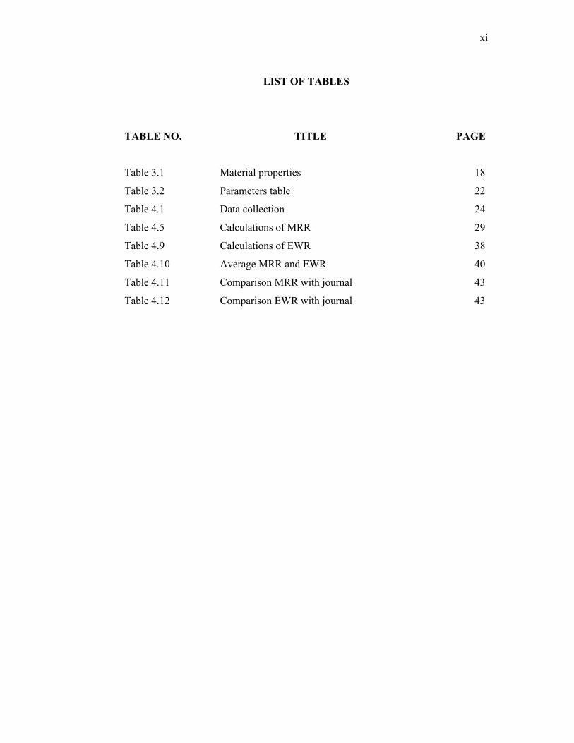
xi
LIST OF TABLES
TABLE NO. TITLE PAGE
Table 3.1 Material properties 18
Table 3.2 Parameters table 22
Table 4.1 Data collection 24
Table 4.5 Calculations of MRR 29
Table 4.9 Calculations of EWR 38
Table 4.10 Average MRR and EWR 40
Table 4.11 Comparison MRR with journal 43
Table 4.12 Comparison EWR with journal 43
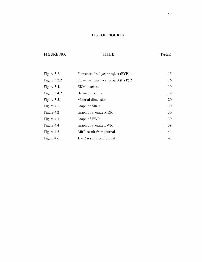
xii
LIST OF FIGURES
FIGURE NO. TITLE PAGE
Figure 3.2.1 Flowchart final year project (FYP) 1 15
Figure 3.2.2 Flowchart final year project (FYP) 2 16
Figure 3.4.1 EDM machine 19
Figure 3.4.2 Balance machine 19
Figure 3.5.1 Material dimension 20
Figure 4.1 Graph of MRR 30
Figure 4.2 Graph of average MRR 30
Figure 4.3 Graph of EWR 39
Figure 4.4 Graph of average EWR 39
Figure 4.5 MRR result from journal 41
Figure 4.6 EWR result from journal 42
Related Documents