EDM Calibration Handbook EDM Calibration Handbook v15 NATA Accreditation Number 15005 Page 1 of 29 EDM CALIBRATION HANDBOOK October 2021

Welcome message from author
This document is posted to help you gain knowledge. Please leave a comment to let me know what you think about it! Share it to your friends and learn new things together.
Transcript
EDM Calibration Handbook
EDM Calibration Handbook v15 NATA Accreditation Number 15005 Page 1 of 29
EDM CALIBRATION
HANDBOOK
October 2021
EDM Calibration Handbook
EDM Calibration Handbook v15 NATA Accreditation Number 15005 Page 2 of 29
Published by: Office of the Surveyor-General and Land Information Environment, Planning and Sustainable Development Directorate Level 1, 480 Northbourne Ave Dickson, ACT 2602 Email: [email protected] Phone: 6207 1639 Web: www.planning.act.gov.au/survey-spatial-data-and-maps Any queries regarding this Handbook may be directed as above. Approved by: Jeffrey Brown Surveyor-General of the ACT Date of Approval: 11 November 2021
EDM Calibration Handbook
EDM Calibration Handbook v15 NATA Accreditation Number 15005 Page 3 of 29
TABLE OF CONTENTS PREFACE ........................................................................................................................................ 4
QUALITY POLICY STATEMENT .............................................................................................. 5
(1) INTRODUCTION............................................................................................................................ 6
(2) TRACEABILITY OF MEASUREMENT OF LENGTH TO THE NATIONAL STANDARD ....................... 9
(3) EDM CALIBRATION - INSTRUMENT CONSTANTS AND ERRORS ............................................... 11
(4) WATSON EDM BASELINE ........................................................................................................... 14
(5) STANDARD EDM CALIBRATION: GENERAL PROCEDURE .......................................................... 16
(6) REDUCTION AND INTERPRETATION .......................................................................................... 21
(7) WORK HEALTH AND SAFETY ..................................................................................................... 22
REFERENCES .................................................................................................................................... 23
APPENDIX A - LOCALITY PLAN OF THE WATSON EDM BASE ......................................................... 24
APPENDIX B - SAMPLE BOOKING SHEET ........................................................................................ 25
APPENDIX C – SAMPLE EDM CALIBRATION CERTIFICATE ....................................... 27
APPENDIX D - SAMPLE EDM CALIBRATION REQUEST FORM ........................................................ 29
¡¡RADIO FREQUENCY INTERFERENCE!! Radio frequency (RF) interference is the radiation of RF energy that can interfere with the proper functioning of nearby devices.
Some digital thermometers and weather stations used to measure temperature and pressure are susceptible to this interference.
Thus, when radioing in meteorological readings using UHF transceivers, keep the transceiver well away from your meteorological equipment.
EDM Calibration Handbook
EDM Calibration Handbook v15 NATA Accreditation Number 15005 Page 4 of 29
Preface The Surveyor-General of the Australian Capital Territory sets standards for cadastral surveys pursuant to the Surveyors (Surveyor-General) Practice Directions 2021 (No 1). This includes requirements for the calibration and standardisation of equipment used in surveying. To help registered surveyors meet these standards, the Surveyor-General is responsible for providing certified calibration facilities and advice to enable practical implementation. The Surveyors (Surveyor-General) Practice Directions 2021 (No 1) sets out the requirements for the calibration and standardisation of EDM instruments. It states that these instruments must be calibrated on a certified baseline at intervals not exceeding 12 months or, more frequently if conditions so warrant. This Handbook provides the specification and practice direction for achieving calibration and standardisation of EDM instruments at the ACT’s baseline at Watson. The Surveyor-General is a Verifying Authority for length and is responsible for the annual re-certification of the baseline as a subsidiary standard of length. The Surveyor-General, through the Office of the Surveyor-General and Land Information, provides for the continued certification of the baseline and periodic updates of this Handbook.

EDM Calibration Handbook
EDM Calibration Handbook v15 NATA Accreditation Number 15005 Page 5 of 29
Quality Policy Statement The Office of the Surveyor-General and Land Information of the ACT Government, as a Verifying Authority for Length, is committed to providing quality EDM calibration and testing services to the local surveying industry in a timely manner. This will be achieved through a total and continuous commitment to the Directorate’s corporate vision, to our quality principles and to good professional practice. The Verifying Authority Management System is designed to comply with the requirements of the international standard ISO/IEC 17025:2017 (the Australian equivalent is AS ISO/IEC 17025:2018). The Management System provides the basis for achieving our commitment to provide quality calibration and testing services and to continuously improve all aspects of our products and their delivery to our customers. The Office of the Surveyor-General and Land Information welcomes customers’ suggestions for product improvement, which will then be used to provide our customers with the products and services most suited to their expectations. Staff of the Office of the Surveyor-General and Land Information will always be professional, helpful and courteous in dealing with our customers. All Office of the Surveyor-General and Land Information staff, particularly those with managerial, technical and supervisory responsibilities, will actively implement this policy and support the Management System.
EDM Calibration Handbook
EDM Calibration Handbook v15 NATA Accreditation Number 15005 Page 6 of 29
(1) Introduction (1.1) This handbook deals with the calibration and standardisation of Electro-optical Distance
Meters (EDM) and the EDM sections of electronic tacheometers (total stations). It also gives a description of the constants and errors associated with EDM instruments and the procedures necessary to calibrate such instruments on the EDM Calibration Baseline in the suburb of Watson in the Australian Capital Territory. “Calibration” of EDM is to do with the determination of instrumental errors (see 3. below); “Standardisation” is concerned with comparison of the instrument to a standard of length that is traceable to the national standard. To be considered as being standardised, instruments must be calibrated within a prescribed level of precision (see 2.2). NB: throughout this document “EDM” is used generically to denote both stand-alone EDM instruments and total stations.
(1.2) The Watson EDM Baseline is maintained as a Reference Standard for length and is described
in Chapter 4. It is set out on the Sprent-Zwart (Hobart) principle as described by Sprent (1980). Index error, scale factor and cyclic error can be determined from measurements taken on this baseline.
(1.3) When a Certificate of Verification (Regulation 13, National Measurement Regulations 1999
(Cth)) has been issued for this baseline by the ACT Surveyor-General, the baseline can then be used to verify EDM instruments and therefore traceability of EDM measurements to the national standard of length is possible. Where a Regulation 13 Certificate is required for an EDM, qualified Office of the Surveyor-General and Land Information (OSG&LI) personnel must perform the measurements and calculations (see 2.5).
(1.4) Most calibration activities undertaken at the Watson EDM Baseline involve EDM users who
require a calibration to comply with Direction 17(b) of the ACT Surveyors (Surveyor-General) Practice Directions 2021 (No.1) or Clause 14(2) & (4) of the NSW Surveying and Spatial Information Regulation 2017. They usually do not require a Regulation 13 Certificate for their EDM. This Handbook is intended for calibrating and standardising EDMs in “standard” mode as opposed to “reflectorless” mode. For those interested in reflectorless testing, refer to Evans (2014) as listed in the References.
EDM instruments should be calibrated on a pillared baseline:
• after being repaired or serviced; • after receiving rough treatment or hard knocks; • before being used for high-accuracy surveys; and
EDM Calibration Handbook
EDM Calibration Handbook v15 NATA Accreditation Number 15005 Page 7 of 29
• at regular intervals not exceeding twelve months. (1.5) The observing procedures outlined in Chapter 5 are based on the "Instructions on the
Verification of Electro-optical Short-Range Distance Meters on Subsidiary Standards of Length in the Form of EDM Calibration Baselines" (Rüeger, 1984).
(1.6) Reduction of the calibration measurements is explained in Chapter 6. A sample of the
calibration certificate is given at Appendix C. (1.7) There are two calibration options available using the Watson Baseline:
(1.7.1) Standard EDM Calibration by the Customer: A Standard EDM Calibration performed by the customer will satisfy the legislative requirements mentioned in section 1.4 above. Combination padlocks have been fitted to the pillar lids and the access gate. Access to the Watson Baseline must be booked, and the customer will be provided with the combination code at the time of booking.
This Handbook, the booking sheet and the EDM Calibration software BASELINE are available for download at: www.planning.act.gov.au/survey-spatial-data-and-maps/general-survey-information/baseline-calibrations Customers are required to supply their own meteorological equipment, umbrellas and printed copies of the booking sheets. The customers meteorological equipment can be compared to the standardised OSG&LI thermometers and barometers upon request (see 5.1.12).
(1.7.2) Regulation 13 Certificate: Calibrations that require issuance of a Regulation 13
Certificate are performed on EDMs that are to be used on projects that require the highest standard of accuracy, such as dam and bridge deformation surveys, or for the calibration of a state secondary EDM baseline. The process involves a more rigorous observational regime than for a standard EDM calibration.
If a Regulation 13 Certificate is required, OSG&LI personnel MUST perform the calibration and reduction. The charge would be at the standard hourly rate applicable at that time, plus an additional cost for the supply of a Certificate under Regulation 13 of the National Measurement Regulations 1999. Additional costs would be incurred if difficulties are encountered with individual instruments. Regulation 13 Certificates are valid for one year only. (See 1.8 below.)
EDM Calibration Handbook
EDM Calibration Handbook v15 NATA Accreditation Number 15005 Page 8 of 29
(1.8) Due to the amount of time required to perform a Regulation 13 calibration, OSG&LI can only
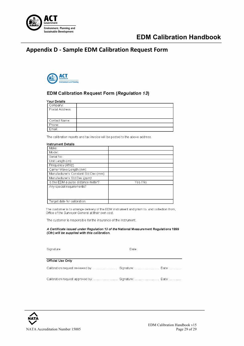
offer to perform this level of calibration on one EDM per customer per year. When a Regulation 13 certificate is to be issued (see 1.7.2 above), the customer is required to complete an “EDM Calibration Request Form”, an example of which is given at Appendix D. The request for calibration will be reviewed by OSG&LI staff and an offer to perform the EDM calibration may be sent to the customer if:
• The customer’s calibration requirements, including the calibration method, are
capable of being met by OSG&LI; • OSG&LI has the capacity and resources to meet those requirements; and
• The calibration method is capable of meeting the customer’s requirements.
Any differences between the request and the offer to perform the EDM calibration shall be
resolved before any calibration activities commence.
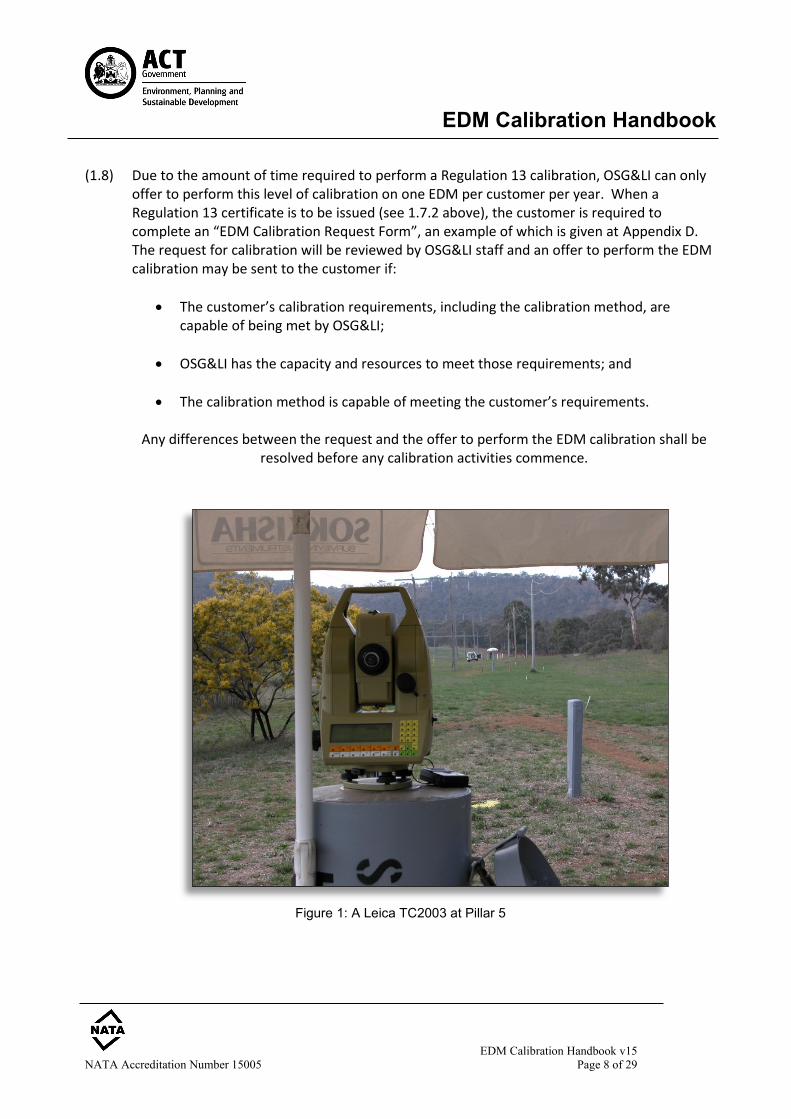
Figure 1: A Leica TC2003 at Pillar 5
EDM Calibration Handbook
EDM Calibration Handbook v15 NATA Accreditation Number 15005 Page 9 of 29
(2) Traceability of Measurement of Length to the National Standard (2.1) The Surveyor-General is appointed as a Verifying Authority for Length, authorised under
Regulation 73 of the National Measurement Regulations 1999 (Cth) of the National Measurement Act 1960 (Cth). Under Regulation 13 the Surveyor-General can certify reference standards of length at specified levels of precision. Furthermore, the Office of the Surveyor-General & Land Information is accredited by the National Association of Testing Authorities, Australia (NATA) in the field of metrology (Laboratory No. 15005).
(2.2) In 1983 the National Standards Commission (NSC) -now incorporated into the National
Measurement Institute (NMI)- formed a working party on the “Calibration of Electromagnetic Distance Measuring (EDM) Equipment”. Following the recommendations of this working party and research by the NSC, it was established that monumented baselines could be certified as subsidiary standards of length under Regulation 13 of the National Measurement Regulations 1999 to provide legal traceability for EDM measurements. Recommendations of specific interest from the NSC working party are:
No.2 To be certified as a subsidiary standard a baseline must be capable of being calibrated with an uncertainty of ±[1.5 + (20 x 10-3 x L)] mm at the 95% level of confidence where L is the interval length in metres.
No.8 It is recommended that, in general, the minimum standard for the uncertainty of calibration of an EDM, assuming calibration against a monumented base, should be ±[4 + (20 x 10-3 x L)] mm at the 95% level of confidence where L is the interval length in metres.
(2.3) The Watson EDM Baseline has been certified by the Surveyor-General as a reference standard
under Regulation 13 of the National Measurement Regulations 1999 (Cth). The calibration of the EDM Baseline is certified annually in accordance with Recommendation No.2.
(2.4) The calibration procedures outlined in this Handbook (see Chapter 5) and the analysis
techniques contained in the calibration software (see Chapter 6) are capable of meeting the requirement of Recommendation No.8.
(2.5) The Surveyor-General can issue a Regulation 13 certificate for a surveyor's EDM instrument if:
• it is calibrated on the Watson EDM Baseline and a valid Regulation 13 Certificate exists for the EDM Baseline at the time of calibration;
EDM Calibration Handbook
EDM Calibration Handbook v15 NATA Accreditation Number 15005 Page 10 of 29
• the instrument errors are determined in accordance with the recommendations of
the National Standards Commission working party; and
• the calibration is performed by qualified OSG&LI staff (see 1.7.2 above).
EDM Calibration Handbook
EDM Calibration Handbook v15 NATA Accreditation Number 15005 Page 11 of 29
(3) EDM Calibration - Instrument Constants and Errors (3.1) An EDM instrument is calibrated on a baseline to determine instrument constants and errors. If
significant, corrections should be applied to EDM measurements taken subsequent to the calibration.
(3.2) A series of measurements on a baseline can also be used to check the performance and
reliability of the instrument over time and to assess its precision against the manufacturer's specifications.
(3.3) The three distinct systematic errors that may occur in EDM are:
index (or zero) error; scale error; and
cyclic or short periodic error, in instruments of the phase-comparison type.
Note: EDM instruments of the pulse-measurement type typically are free of cyclic errors. (3.4) Additive Constant (correction for Zero or Index error) (3.4.1) All distances measured by a particular EDM/reflector combination are subject to a
constant error. It is caused by three factors: • electrical delays, geometric detours, and eccentricities in the EDM; • differences between the electronic centre and the mechanical centre of the EDM;
and • differences between the optical and mechanical centres of the reflector.
(3.4.2) This error may vary:
• with a change of reflectors; • after the EDM or reflector receives a jolt; • with different instrument mountings; and • after servicing.
(3.4.3) The additive constant or zero/index correction is an algebraic constant to be applied directly to every measured distance.
EDM Calibration Handbook
EDM Calibration Handbook v15 NATA Accreditation Number 15005 Page 12 of 29
(3.5) Scale Error
(3.5.1) Scale error is proportional to the length of the line measured and is caused by: • the drift in frequency of the quartz crystal oscillator in the instrument;
• errors in the measured temperature, pressure and humidity which affect the velocity
of the propagation; and
• non-homogeneous emission/reception patterns from the emitting and receiving diodes (phase inhomogeneities).
(3.5.2) The scale frequency can be checked by: • comparison of the EDM’s modulation frequency against a test reference signal;
and/or • a functional test over a pillared baseline of known distance.
(3.6) Cyclic Error (or Short Periodic Error)
(3.6.1) Cyclic error is caused by the non-linearity in amplitude modulation of the carrier wave and phase measurement. This cyclic error varies across the modulated wavelength.
(3.6.2) For an instrument in good adjustment this error is normally small. However, its presence must be determined as an indication of the instrument's adjustment.
(3.6.3) Cyclic error is usually sinusoidal in nature, with a wavelength equal to the unit length of the EDM. The unit length is the scale on which the EDM measures the distance, and is derived from the fine measuring frequency. Unit length is equal to one half of the modulation wavelength of an EDM (Rüeger, 1990).
(3.6.4) As cyclic error repeats itself for every unit length contained within a measured distance,
its sign and magnitude varies depending on the length measured. The magnitude of the error could be in the order of 5-10mm, however in modern EDM instruments it is usually less than 2mm (negligible). Cyclic error can increase in magnitude as an EDM’s components age.
(3.6.5) Cyclic error can be determined by a series of check measurements made on EDM
baselines of the Sprent-Zwart or Schwendener designs (Sprent & Zwart, 1978).
EDM Calibration Handbook
EDM Calibration Handbook v15 NATA Accreditation Number 15005 Page 13 of 29
(3.6.6) The Sprent-Zwart design of the Watson Baseline allows for index and scale errors to be determined free of the effect of any cyclic error present in the EDM.
A series of measurements is made from the first pillar and then a second series is made from second pillar, which is at a distance (D) from the first pillar:
D = (x + 0.5) U
Where: U = the instrument's unit length (m), and x = an integer representing a whole number of unit lengths. Cyclic error thus cancels out due to the errors affecting the distances being equal in magnitude but opposite in sign. The index error and scale error can thus be determined unaffected by the cyclic error.
EDM Calibration Handbook
EDM Calibration Handbook v15 NATA Accreditation Number 15005 Page 14 of 29
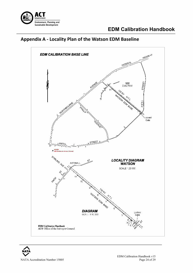
(4) Watson EDM Baseline (4.1) The EDM baseline is situated in Block 3 Section 65 Watson. Access is via a locked gate off Antill
Street (see locality plan - Appendix A). (4.2) This baseline is a modification of the original Sprent-Zwart (Hobart) design (Sprent & Zwart,
1978) consisting of 11 forced centring pillars spread over approximately 1118 metres. (4.3) The forced-centring pillars were installed to obtain high set-up accuracy as well as for
convenience and time saving. On the top of each pillar is a brass plate containing a 5/8 inch UNC threaded bolt and is protected by a lockable cap. Three sets of 3 deep driven rods have been placed along the baseline to monitor pillar movement.
(4.4) The baseline has been constructed on a sloping site with a concave profile, which allows for
intervisibility between pillars, and eliminates the need for them to be greatly offset. (4.5) The calibration of the EDM baseline is made in accordance with Recommendation No.2 of the
National Standards Commission's Working Party (see 2.2 above). The baseline has been measured by a prescribed instrument and absolute distances have been given to the pillar intervals. These absolute distances are used to determine the scale error.
NOTE: A prescribed instrument is a distance measuring instrument of a type approved by the National Measurement Institute for the calibration of EDM baselines, and one that holds current certification under Regulation 13 of the National Measurement Regulations 1999.
(4.6) On 24 January 1987, a Certificate of Verification under Regulation 80 of the National
Measurement Act 1960 was first issued for the Watson Baseline by the Commonwealth Surveyor-General. This Certificate of Verification was renewed annually. Since 1999, this certification is now made under Regulation 13 of the National Measurement Regulations 1999 (Cth), and is usually renewed annually by the ACT Surveyor-General, whom the National Measurement Institute (formerly the National Standards Commission) has appointed as a Verifying Authority for Length.
(4.7) The first 3 pillars of the Watson Baseline have been placed at chainages 0m, 5m, and 7.5m,
while Pillar 4 is at chainage 54.8m. The unit length of the EDM being calibrated will govern
EDM Calibration Handbook
EDM Calibration Handbook v15 NATA Accreditation Number 15005 Page 15 of 29
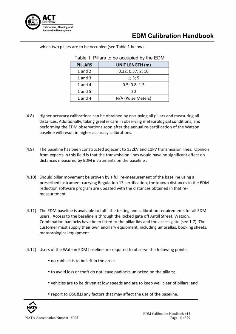
which two pillars are to be occupied (see Table 1 below).
Table 1: Pillars to be occupied by the EDM PILLARS UNIT LENGTH (m) 1 and 2 0.32; 0.37; 2; 10 1 and 3 1; 3; 5 1 and 4 0.5; 0.8; 1.5 1 and 5 20 1 and 4 N/A (Pulse Meters)
(4.8) Higher accuracy calibrations can be obtained by occupying all pillars and measuring all
distances. Additionally, taking greater care in observing meteorological conditions, and performing the EDM observations soon after the annual re-certification of the Watson baseline will result in higher accuracy calibrations.
(4.9) The baseline has been constructed adjacent to 132kV and 11kV transmission lines. Opinion
from experts in this field is that the transmission lines would have no significant effect on distances measured by EDM instruments on the baseline .
(4.10) Should pillar movement be proven by a full re-measurement of the baseline using a
prescribed instrument carrying Regulation 13 certification, the known distances in the EDM reduction software program are updated with the distances obtained in that re-measurement.
(4.11) The EDM baseline is available to fulfil the testing and calibration requirements for all EDM
users. Access to the baseline is through the locked gate off Antill Street, Watson. Combination padlocks have been fitted to the pillar lids and the access gate (see 1.7). The customer must supply their own ancillary equipment, including umbrellas, booking sheets, meteorological equipment.
(4.12) Users of the Watson EDM baseline are required to observe the following points: no rubbish is to be left in the area; to avoid loss or theft do not leave padlocks unlocked on the pillars;
vehicles are to be driven at low speeds and are to keep well clear of pillars; and report to OSG&LI any factors that may affect the use of the baseline.
EDM Calibration Handbook
EDM Calibration Handbook v15 NATA Accreditation Number 15005 Page 16 of 29
(5) Standard EDM Calibration: General Procedure (5.1) When testing or calibrating EDM instruments the following procedures are to be followed (see
1.4 above):
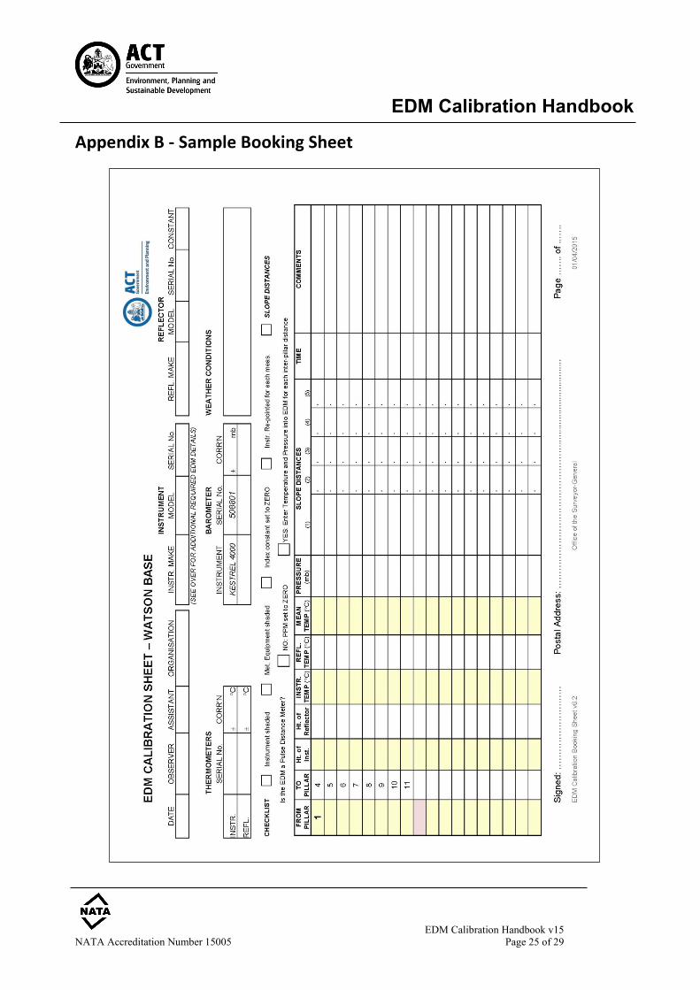
(5.1.1) Booking Sheets or Recording Data All observations shall be recorded on the EDM Calibration booking sheet at the time they are made. When mistakes occur, each mistake shall be crossed out, not erased or made illegible, and the correct value entered alongside. All such alterations shall be signed or initialled by the person making the correction, and the date of change should also to be recorded.
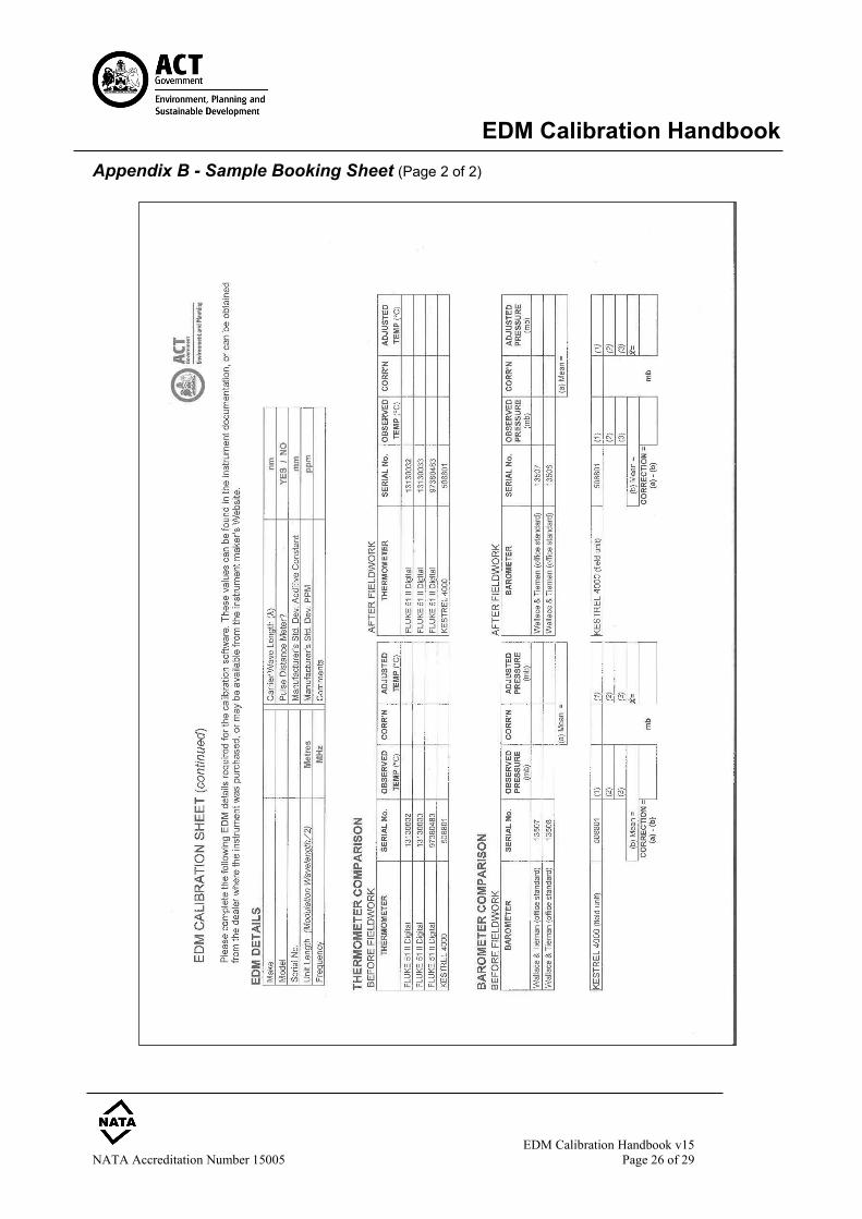
Comparisons between field and OSG&LI standard meteorological equipment can be made by OSG&LI and be recorded on the reverse page (p2) of the booking sheet prior to, or after the observations.
All details must be recorded and signed and dated by the operator. Completed booking sheets should be forwarded to OSG&LI for records maintenance and monitoring of the baseline (see 6.4).
Units of measurement used are: metres (m) for distance, degrees Celsius (°C) for temperature and millibars (mb) for atmospheric pressure, and if measured, relative humidity (%). (BASELINE refers to hectopascals for units of atmospheric pressure.) Note: 1 millibar (mb) = 100 pascals (Pa) = 1 hectopascal (hPa) = 0.750 28 mmHg = 0.029 53 inHg
(5.1.2) EDM Specifications Ascertain the unit length (m) of the instrument (half of the modulation wavelength of the fine measurement) prior to arriving at the EDM baseline, as this influences the measuring procedure. This length is generally quoted in the technical specifications in the instrument manufacturer's handbook. Record the unit length on the booking sheet. Likewise ascertain the frequency (Hz), carrier wavelength (nm), and the manufacturer’s stated standard deviations of the EDM and record these on the booking sheet. For time-of-flight EDMs (pulse distance meters), ascertain the carrier wavelength and record this on the booking sheet.
EDM Calibration Handbook
EDM Calibration Handbook v15 NATA Accreditation Number 15005 Page 17 of 29
(5.1.3) Preparation of Equipment
Check the levelling bubbles on all tribrachs, reflectors and the theodolite, and if necessary, adjust before observing distances.
(5.1.4) Set-up and Shade Set the instrument on pillar 1. An umbrella must shade the instrument for the duration of the calibration observations as well as during the warm-up period prior to the commencement of readings. To improve the accuracy of the calibration an umbrella may also be used to shade the reflector.
(5.1.5) Atmospheric Correction Control
Determine if the EDM is a phase-comparator type or a pulse distance meter. If the EDM is a phase-comparator , then the atmospheric correction control (ppm) should be set to zero if possible. For instruments requiring meteorological observations to be input, enter the temperature and pressure for which the instrument is standardised (i.e. ppm = 0). If the EDM is a pulse distance meter, the instrument should be set such that ppm = zero, and the measured distances are subsequently reduced for the 1st velocity correction prior to upload into the BASELINE software for reduction. This is the preferred method, as it eliminates the possibility of entering erroneous meteorological observations into the instrument. A spreadsheet written for this purpose is now provided with the BASELINE reduction software. Alternatively, distance readings may initially be first-velocity corrected by the on-board EDM software. In this case, the ambient temperature and pressure must be entered into the EDM before observing each inter-pillar distance. It is therefore essential that any corrections to the meteorological observations are applied before inputting into the instrument.
(5.1.6) Additive Constant
Record the setting of the reflector additive constant on the booking sheet. Set it to zero if possible.
(5.1.7) Reflector Type Modern total stations have a number of pre-defined reflector options, with their default additive constants stored onboard. Ensure that the appropriate Reflector Type is selected. Furthermore, review that the selected measurement mode is appropriate for the test observations.
EDM Calibration Handbook
EDM Calibration Handbook v15 NATA Accreditation Number 15005 Page 18 of 29
Note: do not observe to a reflector in “reflectorless” mode (Evans, 2014).
(5.1.8) Power
The EDM's battery should be fully charged prior to performing the calibration. If possible, the instrument should remain switched on during the whole calibration.
(5.1.9) Height of Instrument
With the EDM instrument levelled, measure the height of the instrument (height of the trunnion axis) above the brass plate in the pillar. Record this height at each occupied pillar.
(5.1.10) Reflector Mountings
The same reflector mounting and tribrach combination should be used for all measurements. If it is not possible to measure the longer distances with one reflector, use a multiple-reflector mounting. With this arrangement it will be necessary to remove or block out some reflectors for the shorter distances.
The height of the centre of the reflector prism above the brass plate must be measured and recorded at each pillar. If a multiple reflector arrangement is used, the reflector height in both the single and multiple configurations is recorded on the booking sheet.
The reflector must have a unique identification, which must be recorded on the booking sheet.
(5.1.11) Levelling of Equipment
All bubbles must be carefully levelled before distances are observed (see 5.1.3 above).
(5.1.12) Meteorological Observations
Field meteorological equipment can be compared to standardised OSG&LI thermometers and barometers. Comparisons between field and standardised equipment will be recorded on the booking sheets.
Temperature (°C) must be measured in the shade at the instrument and also at the reflector. Temperature is measured at instrument/reflector height and is to be observed for each inter-pillar interval. The atmospheric pressure (mb or hPa) must be measured in the shade at the
EDM Calibration Handbook
EDM Calibration Handbook v15 NATA Accreditation Number 15005 Page 19 of 29
instrument station for each inter-pillar distance. To obtain a higher accuracy calibration, atmospheric pressure can also be observed in the shade at the reflector, for each inter-pillar interval. Note: the typical atmospheric pressure readings at the Watson EDM Baseline are between 930 – 970mb, depending on meteorological conditions. The significance of errors in the meteorological observations on the EDM distance can be summarised as follows (for red laser/near infra-red type EDMs):
• An error in temperature of 1°C affects the distance by ~1ppm • An error in pressure of 1hPa/1mb affects the distance by ~0.3ppm
Although humidity has an even smaller effect on measurements taken by infra-red or laser EDMs, relative humidity (%), or psychrometric observations can be taken to further improve the accuracy of the calibration. OSG&LI meteorological equipment will not be loaned out. Users will need to provide their own meteorological equipment, and may compare their equipment to standardised OSG&LI equipment before or after fieldwork.
(5.1.13) Calibration Measurements
For each inter-pillar distance, a minimum of five (5) individual distance measurements are made, re-pointing after each measurement. Pointing can be made optically or electronically as prescribed by the instrument manufacturer. To improve the accuracy of the calibration, additional distances may be measured.
(5.1.14) Sequence
From pillar 1, measure distances to pillars 4 - 11 in turn. Then:
• If the instrument has a unit length of 0.32, 0.37, 2 or 10m, shift to pillar 2.
• If the unit length is 1, 3 or 5m, shift to pillar 3. Then measure to pillars 11 - 4 in turn. The sequence requires the field assistant to move up-and-down the line only once. For instruments with a unit length of 0.5, 0.8 or 1.5m or pulse meters, measure from pillar 1 to pillars 4 - 11 and from pillar 4 to pillars 11 - 5, and then measure to 3 – 1 in turn.
For instruments with a unit length of 20m, measure from pillar 1 to pillars 4 - 11 and from pillar 5 to pillars 11 - 6, and then measure to pillars 4 - 1 in turn.
NOTE: Refer to Table 1 above (p14) to determine which two pillars to occupy.
EDM Calibration Handbook
EDM Calibration Handbook v15 NATA Accreditation Number 15005 Page 20 of 29
Higher order calibrations will be obtained by setting up on all pillars and measuring to all other pillars (the short distances between pillars 1, 2 and 3 are not observed).
(5.1.15) Comparison of Reflectors
Once all inter-pillar distances have been measured to the one uniquely identified reflector, compare this reflector with the remaining reflectors by measuring to each in turn. This should be performed on a short line (pillar 4 to pillar 3) by comparing the slope distances. However if reflectors vary in height, horizontal distances should be observed, including the reflector used for the calibration. Where found to be significant, variations should be applied as corrections to the additive constant. It is for this reason that all reflectors should be uniquely numbered. Subsequent calibrations of the EDM should be performed using the same uniquely numbered reflector, in order to compile a calibration history for the instrument-reflector combination. Note: Some users of the baseline, when calibrating multiple instruments on the one day, set reflectors on every pillar in order to speed up the process when calibrating multiple EDMs. However, this practice might not give reliable calibration results, even if all reflector-tribrach combinations are of identical make. This is because there may be small variations in the index errors of the reflectors. Although the results of the instrument constant comparison against NMI’s minimum standards (±( 4mm + 20ppm)) may result in a “PASS”, it will not reflect the EDMs true precision unless the same reflectors are used for each calibration. AND that these same reflector-tribrach combinations be placed on the same pillars year-in year-out.
EDM Calibration Handbook
EDM Calibration Handbook v15 NATA Accreditation Number 15005 Page 21 of 29
(6) Reduction and Interpretation (6.1) The EDM Calibration software BASELINE developed by Landgate, Western Australia, is used to
determine the instrument constants, errors and their associated uncertainties from field observations for individual EDM instruments. The National Measurement Institute and the ICSM Geodesy Working Group have approved the use of this program.
(6.2) Instrument details and measured distances (and observed meteorological details for phase-
comparator EDMs) are entered interactively, or via upload of a text file correctly formatted for BASELINE. After the observed data is reduced to obtain horizontal distances and their associated standard deviations, a least squares adjustment is performed. This computes the instrument corrections and their associated uncertainties. The adjustment is made as described in Rüeger (1996) for modelling systematic errors in EDM measurements.
(6.3) The program generates an EDM Calibration Report, which includes baseline data, equipment
details, individual observed data, adjusted observations, index correction, scale factor, (cyclic error for phase-comparator types) and variance factor. It also states the calculated uncertainty of the instrument correction at the 95% confidence level for standardised intervals.
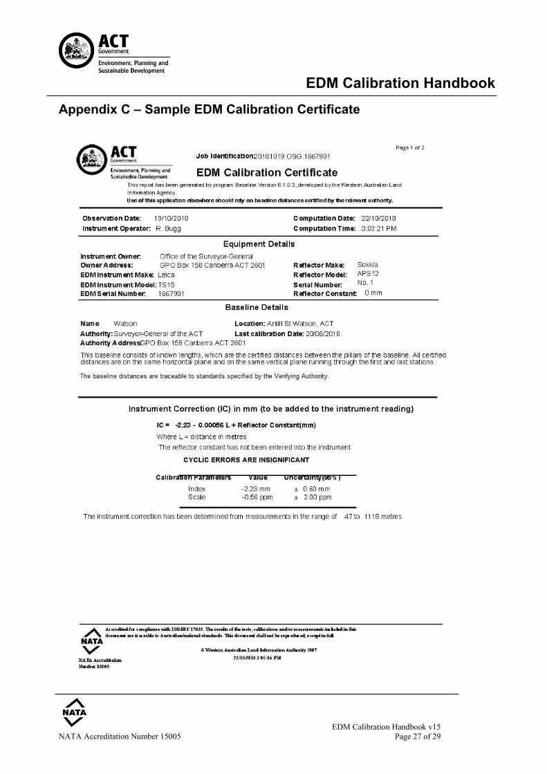
(6.4) The program also generates a concise EDM Calibration Certificate (see Appendix C). The
Calibration Certificate contains the following:
• Associated information including the surveyor's name, date of measurements, baseline details and details of the EDM and reflector are listed. The job identification name is also given.
• The instrument correction formula used in the computation is given, and whether a
reflector constant was entered. A note about significant/insignificant cyclic errors is given if appropriate.
• The Instrument Correction (IC) equation. From this IC equation, a correction (in
millimetres) can be calculated for any distance measured by the EDM in the range of the calibration.
• The instrument calibration parameters (index error, scale error and if significant, the 4
terms modelling the cyclic error), and their uncertainties at the 95% confidence level are listed.
EDM Calibration Handbook
EDM Calibration Handbook v15 NATA Accreditation Number 15005 Page 22 of 29
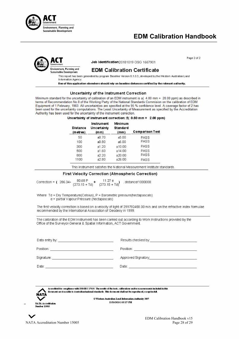
• Uncertainty - the uncertainty of the instrument correction at the 95% confidence level is
listed for various distances. A pass result is given if the instrument uncertainty is less than that prescribed by Recommendation No.8 of the Working Party of the National Standards Commission on the calibration of EDM Equipment (see 2.2).
Where the statistical analysis reveals the calibration to be outside tolerances, adherence to the test method equipment settings and observation data shall be reviewed to determine the source of the inaccurate results. If changes are made, the calibration shall be re-run in the software and further reviewed. If the statistical analysis continues to fall outside of the tolerance, then the calibration is deemed to be nonconforming. When the statistical analysis indicates that the calibration is within tolerance, the EDM Calibration Certificate can be signed by the surveyor. In the event of a calibration found to be nonconforming, OSG&LI staff shall determine required courses of action. This may include a review field of practices and observation techniques used by the surveyor, or the suspension of calibration activities at the EDM baseline. Upon a successful calibration, the instrument owner must send via email a PDF file of the calibration report and certificate for each instrument calibrated, along with colour PDFs of the observation booking sheets. Send via the OSG&LI mailbox, viz., [email protected] Providing this information is vital as it allows OSG&LI ongoing monitoring for any pillar movement at the baseline, and to maintain reassurance in the calibration process. Assistance to surveyors having issues with calibrations is also facilitated. The recommended file-naming convention is: Date (yyyymmdd); Instrument Owner; Serial Number, e.g. 20150202 OSG 100614. For booking sheets, the preferred style is similar, e.g. 20150202 Booking Sheet i.e., the date links the calibration outputs to the observation data.
(6.5) A working knowledge of the instrument correction (IC) can be obtained from the field
measurements by a simple linear regression analysis of index error and scale factor.
(7) Work Health and Safety (7.1) Persons using the Watson EDM Baseline must comply with the requirements of the current
ACT Work Health and Safety Act, Work Health and Safety Regulations and all relevant WorkSafe ACT guidelines.
EDM Calibration Handbook
EDM Calibration Handbook v15 NATA Accreditation Number 15005 Page 23 of 29
References Evans, G. (2014) A Proposed Method for Testing Reflectorless EDM. Proceedings of the 19th
Association of Public Authority Surveyors Conference, Pokolbin, NSW
C.R. Kennedy (2017). Leica Instrument EDM Specifications, PDF of carrier wavelengths, frequencies, unit lengths, etc., of Leica EDMs since 1990, Sydney, Australia.
Klinge, J. (2007). Baseline Version 5.5 – Calibration of EDM Instruments and Baselines, Landgate,
Western Australia. Land Use Victoria. (2020). EDM Calibration Handbook 17th edition, Office of the Surveyor-General
Victoria, Australia. National Standards Commission. (2001). Verifying Authorities Handbook (Draft), Sydney, Australia. Rüeger, J. M. (1984). Instructions on the Verification of Electro-optical Short-Range Distance Meters
on Subsidiary Standards of Length in the form of EDM Calibration Baselines, Recommendations to the National Standards Commission, School of Surveying, University of New South Wales, Australia.
Rüeger, J. M. (1985). Traceability of Electronic Distance Measurement to National Standards,
Proceedings, 27th Australian Survey Congress, Alice Springs, pp. 49-160. Rüeger, J. M. (1996) Introduction to Electronic Distance Measurement – An Introduction, 4th edition,
Springer-Verlag, Berlin. Spatial Services. (2019). Surveyor General’s Direction No 5 – Calibration of Electronic Distance
Measuring (EDM) Equipment, Bathurst, Australia. Sprent, A. (1980). EDM Calibration in Tasmania, The Australian Surveyor, Vol. 30 No. 4, pp. 213-227. Sprent, A. & Zwart, P. R. (1978). EDM Calibration - A Scenario, The Australian Surveyor, Vol. 29 No. 3,
pp. 157-169. Staiger, R. (Ed.). (2007). Recommended procedures for routine checks of electro-optical distance
meters, Monograph No.9, International Federation of Surveyors (FIG). Trimble Navigation Limited (2008). Atmospheric Correction Formula for Trimble, Spectra Precision
and Nikon Total Stations. Survey Support Bulletin, Dayton, OH USA.
EDM Calibration Handbook
EDM Calibration Handbook v15 NATA Accreditation Number 15005 Page 24 of 29
Appendix A - Locality Plan of the Watson EDM Baseline
EDM Calibration Handbook
EDM Calibration Handbook v15 NATA Accreditation Number 15005 Page 25 of 29
Appendix B - Sample Booking Sheet
EDM Calibration Handbook
EDM Calibration Handbook v15 NATA Accreditation Number 15005 Page 26 of 29
Appendix B - Sample Booking Sheet (Page 2 of 2)
EDM Calibration Handbook
EDM Calibration Handbook v15 NATA Accreditation Number 15005 Page 27 of 29
Appendix C – Sample EDM Calibration Certificate
EDM Calibration Handbook
EDM Calibration Handbook v15 NATA Accreditation Number 15005 Page 28 of 29
EDM Calibration Handbook
EDM Calibration Handbook v15 NATA Accreditation Number 15005 Page 29 of 29
Appendix D - Sample EDM Calibration Request Form
Related Documents