Edited, Compiled and Designed By Ms.Subhashree Sasmita, Executive, Electrical Construction. Mr. Sanjib De, Manager, Electrical Construction. Mr. Awaneesh Pandey, Asst. Manager, Electrical Construction. Under Guidance of Mr. V. V. Namjoshi, Dy. Project Head, Maithon Mr. Ranabir Chakraborty, Head – HR, ENRP Mr. Sumit S. Ghosh, HOD, Electrical Construction. Under Special Guidance of Mr. Sanjay Agarwal – Head ENRP . Mr. Sanjay S. Bhattacharya – Head, Maithon Projects

Welcome message from author
This document is posted to help you gain knowledge. Please leave a comment to let me know what you think about it! Share it to your friends and learn new things together.
Transcript
Edited, Compiled and Designed By
Ms.Subhashree Sasmita, Executive, Electrical Construction.
Mr. Sanjib De, Manager, Electrical Construction.
Mr. Awaneesh Pandey, Asst. Manager, Electrical Construction.
Under Guidance of
Mr. V. V. Namjoshi, Dy. Project Head, Maithon
Mr. Ranabir Chakraborty, Head – HR, ENRP
Mr. Sumit S. Ghosh, HOD, Electrical Construction.
Under Special Guidance of
Mr. Sanjay Agarwal – Head ENRP .
Mr. Sanjay S. Bhattacharya – Head, Maithon Projects
Words from Editorial Team
TATA Power's humble beginning at Maithon showcases
its prowess in delivering such mega projects.
This book encapsulates a long journey of The Team
Maithon leading to the achievement of the final goal of
ushering in a new era of development & prosperity for all
stakeholders. This book captures the Spirit of The Team in
overcoming various hurdles by evolving new ideas &
improving the existing methods.
Sumit Ghosh (Head-Electrical, Construction)
From & On Behalf Of Project Team
Maithon
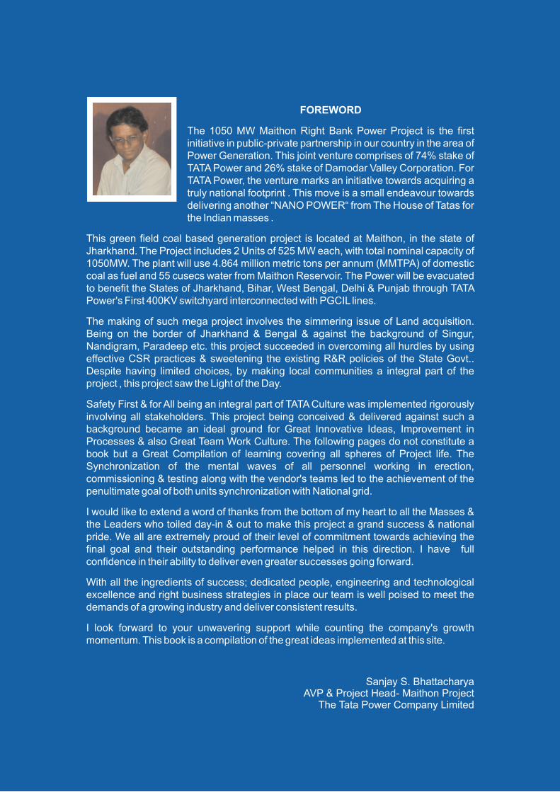
FOREWORD
The 1050 MW Maithon Right Bank Power Project is the first initiative in public-private partnership in our country in the area of Power Generation. This joint venture comprises of 74% stake of TATA Power and 26% stake of Damodar Valley Corporation. For TATA Power, the venture marks an initiative towards acquiring a truly national footprint . This move is a small endeavour towards delivering another “NANO POWER“ from The House of Tatas for the Indian masses .
This green field coal based generation project is located at Maithon, in the state of Jharkhand. The Project includes 2 Units of 525 MW each, with total nominal capacity of 1050MW. The plant will use 4.864 million metric tons per annum (MMTPA) of domestic coal as fuel and 55 cusecs water from Maithon Reservoir. The Power will be evacuated to benefit the States of Jharkhand, Bihar, West Bengal, Delhi & Punjab through TATA Power's First 400KV switchyard interconnected with PGCIL lines.
The making of such mega project involves the simmering issue of Land acquisition. Being on the border of Jharkhand & Bengal & against the background of Singur, Nandigram, Paradeep etc. this project succeeded in overcoming all hurdles by using effective CSR practices & sweetening the existing R&R policies of the State Govt.. Despite having limited choices, by making local communities a integral part of the project , this project saw the Light of the Day.
Safety First & for All being an integral part of TATA Culture was implemented rigorously involving all stakeholders. This project being conceived & delivered against such a background became an ideal ground for Great Innovative Ideas, Improvement in Processes & also Great Team Work Culture. The following pages do not constitute a book but a Great Compilation of learning covering all spheres of Project life. The Synchronization of the mental waves of all personnel working in erection, commissioning & testing along with the vendor's teams led to the achievement of the penultimate goal of both units synchronization with National grid.
I would like to extend a word of thanks from the bottom of my heart to all the Masses & the Leaders who toiled day-in & out to make this project a grand success & national pride. We all are extremely proud of their level of commitment towards achieving the final goal and their outstanding performance helped in this direction. I have full confidence in their ability to deliver even greater successes going forward.
With all the ingredients of success; dedicated people, engineering and technological excellence and right business strategies in place our team is well poised to meet the demands of a growing industry and deliver consistent results.
I look forward to your unwavering support while counting the company's growth momentum. This book is a compilation of the great ideas implemented at this site.
Sanjay S. BhattacharyaAVP & Project Head- Maithon Project
The Tata Power Company Limited

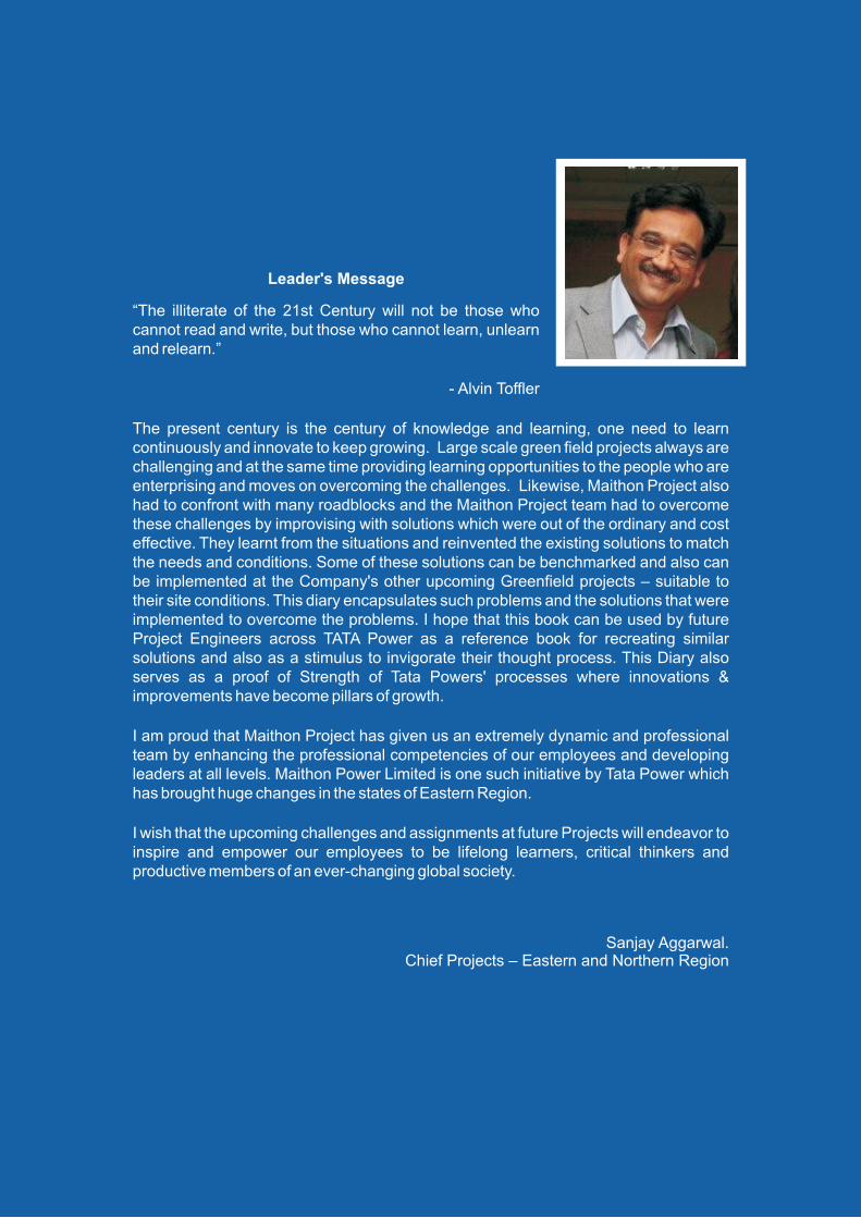
Leader's Message
“The illiterate of the 21st Century will not be those who cannot read and write, but those who cannot learn, unlearn and relearn.”
- Alvin Toffler
The present century is the century of knowledge and learning, one need to learn continuously and innovate to keep growing. Large scale green field projects always are challenging and at the same time providing learning opportunities to the people who are enterprising and moves on overcoming the challenges. Likewise, Maithon Project also had to confront with many roadblocks and the Maithon Project team had to overcome these challenges by improvising with solutions which were out of the ordinary and cost effective. They learnt from the situations and reinvented the existing solutions to match the needs and conditions. Some of these solutions can be benchmarked and also can be implemented at the Company's other upcoming Greenfield projects – suitable to their site conditions. This diary encapsulates such problems and the solutions that were implemented to overcome the problems. I hope that this book can be used by future Project Engineers across TATA Power as a reference book for recreating similar solutions and also as a stimulus to invigorate their thought process. This Diary also serves as a proof of Strength of Tata Powers' processes where innovations & improvements have become pillars of growth.
I am proud that Maithon Project has given us an extremely dynamic and professional team by enhancing the professional competencies of our employees and developing leaders at all levels. Maithon Power Limited is one such initiative by Tata Power which has brought huge changes in the states of Eastern Region.
I wish that the upcoming challenges and assignments at future Projects will endeavor to inspire and empower our employees to be lifelong learners, critical thinkers and productive members of an ever-changing global society.
Sanjay Aggarwal. Chief Projects – Eastern and Northern Region

CHAPTER 1: SAFETY
1.1. Maithon’s safe journey through project 1.2. Some best practices 1.3. Things we’ve done in a uniquely safe way
CONTENT
CHAPTER 2: DESIGN
2.1. Temporary lightning protection for chimney construction 2.2. Cable pathway extra requirement between 400kv Switchyard and
TG building 2.3. Corridor for construction power supply 2.4. 400 kV outgoing conductors stringing at TG end (A– row) 2.5. Modification in trip logic for restricted earth fault in ash handling plant 2.6. Modification in earth fault relay for plant water system
(Transformer feeder) 2.7. Potential transformer circuit modification for line distance
protection 2.8. Raw water intake embankment 2.9. Modification of current circuit for LBB protection 2.10. Generator protection trip circuit supervision modification 2.11. Provision of ramp for coal feeding in track hopper 2.12. Provision of concrete encasing for CW pipe line 2.13. Provision of drilled MS ‐ flat for fixing of wooden door frames in
staff colony 2.14. Portico of technical building 2.15. 6.6kv bus coupler auto changeover scheme for coal handling
system 2.16. Modification of synchronizing circuit during closing of incomer and bus coupler breaker for 6.6kv ash handling system 2.17. Coal handling plant 415v (L.T.) bus coupler auto change over
scheme 2.18. Proposal based on experience of Maithon 400 kV switchyard
commissioning 2.19. Alternate method of plate heat exchanger cooling
CHAPTER 3: ERECTION
3.1. Location of manhole changed at CST roof 3.2. New technologies used for water wall erection in boiler 3.3. Erection of electrodes of ESP 3.4. Procedural change in structural erection for mill & bunker bay 3.5. Casting of chimney raft 3.6. Lightning protection by high masts at construction site 3.7. Compartmentalization of ash pond 3.8. Drain location near railway’s return line 3.9. Staging design of CHP tunnel 3.10. Road construction near railway’s cutting area after providing retaining wall 3.11. TG columns casting 3.12. Relocation of IBD sump pits 3.13. Bunker shell erection by monorail & winch instead of crane 3.14. Pre‐assemblies and lifting of boiler lift structures with all its members
CHAPTER 4: COMMISSIONING
4.1. Power circuit modification for IDCT vibration transmitter 4.2. Avoidance of tripping of MDBFP pump on high vibration in manual mode 4.3. Avoidance of manual priming for sludge transfer pump 4.4. Feeder modification for reliable operation of CW pumps 4.5. Double run cable entry problem in switchgear 4.6. Changes made in piping plan of hot well make up pump 4.7. Modification in ash water pump suction line 4.8. Modification in ECP panel for closing circuit of generator circuit breaker 4.9. HP bypass fast opening lower pressure 4.10. HP bypass fast opening 4.11. Detection of wrong nomenclature of neutral current transformer of
400kv reactor 4.12. Elevator machine room power & ac connection 4.13. Modified mechanical protection for reactor NGR 4.14. Provision of peripheral drain surrounding ash pond . 4.15. Modification in run‐off pit location near stacker re‐claimer . 4.16. NGR connecting cables for station transformer 4.17. Boiler cooling water pump motor cable termination 4.18. DCS electronic earth pits locations 4.19. Provision of cooling tower secondary & tertiary drains 4.20. Glass fixture for switchyard control room floor 4.21. Construction of temporary steel chimney 4.22. LDO gravity unloading 4.23. Use of raw water for Ash Handling system
CHAPTER 5: CRITICAL LEARNING
5.1. Water logging in cable trenches of switchgear room 5.2. Cut‐outs for electrical equipments 5.3. Alternative method for auxiliary cooling system 5.4. Cable pathway for bops 5.5. Generator transformer isolator earth 5.6. Laying of cables for generator transformers, unit aux. Transformers & Station Transformers 5.7. Surge counter mounting on lightning arrestor structure 5.8. Construction of retaining wall at staff colony 5.9. 400kv Maithon switchyard: BUS and DIA stability 5.10. Cooling tower basin make up by gravity 5.11. Shifting of GT through railway line 5.12. Installation of earthing strip at chimney by rope access method
CHAPTER 6: HUMAN RESOURCE
6.1. Alignment of lateral recruits to tata power cultural heritage 6.2. Capability development at Maithon 6.3. Capacity building at Maithon

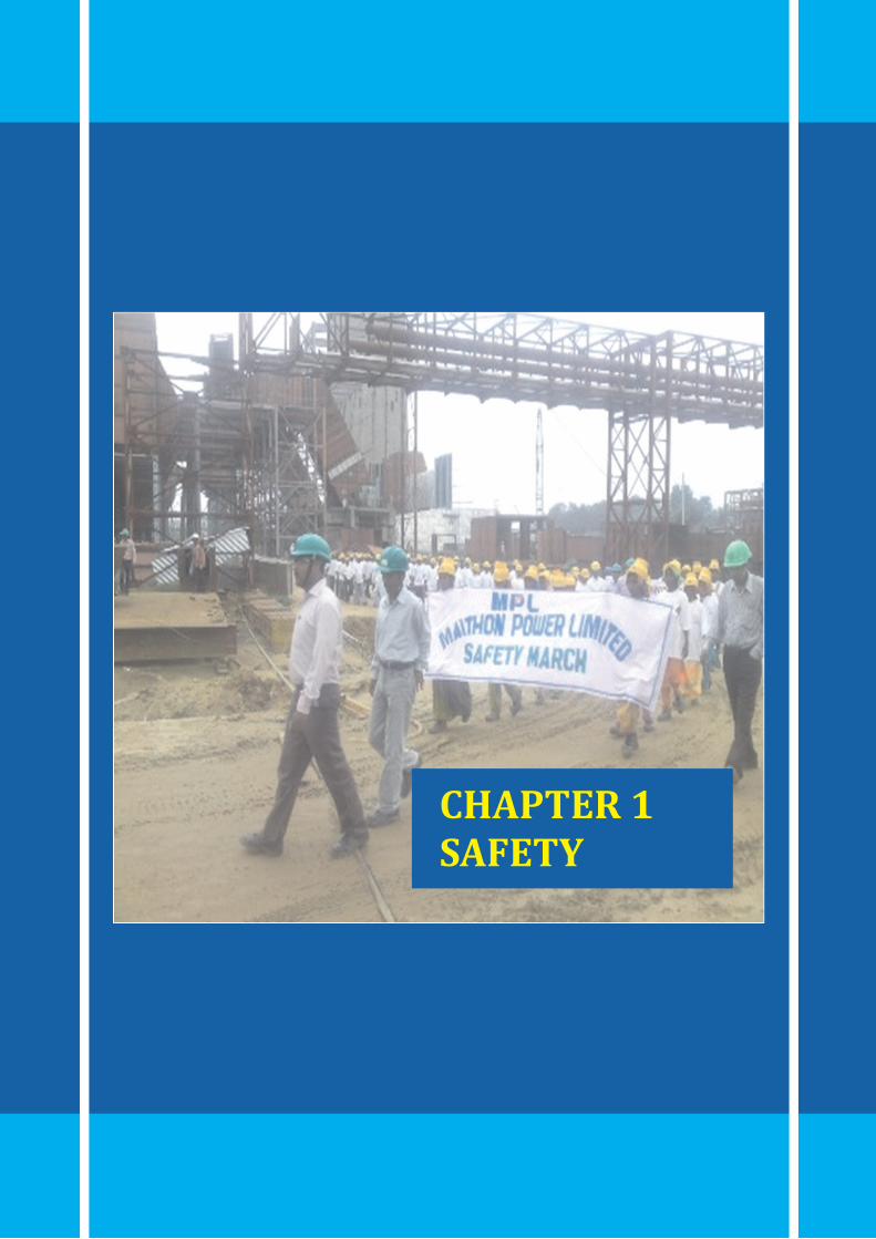
CHAPTER 1SAFETY

2X52
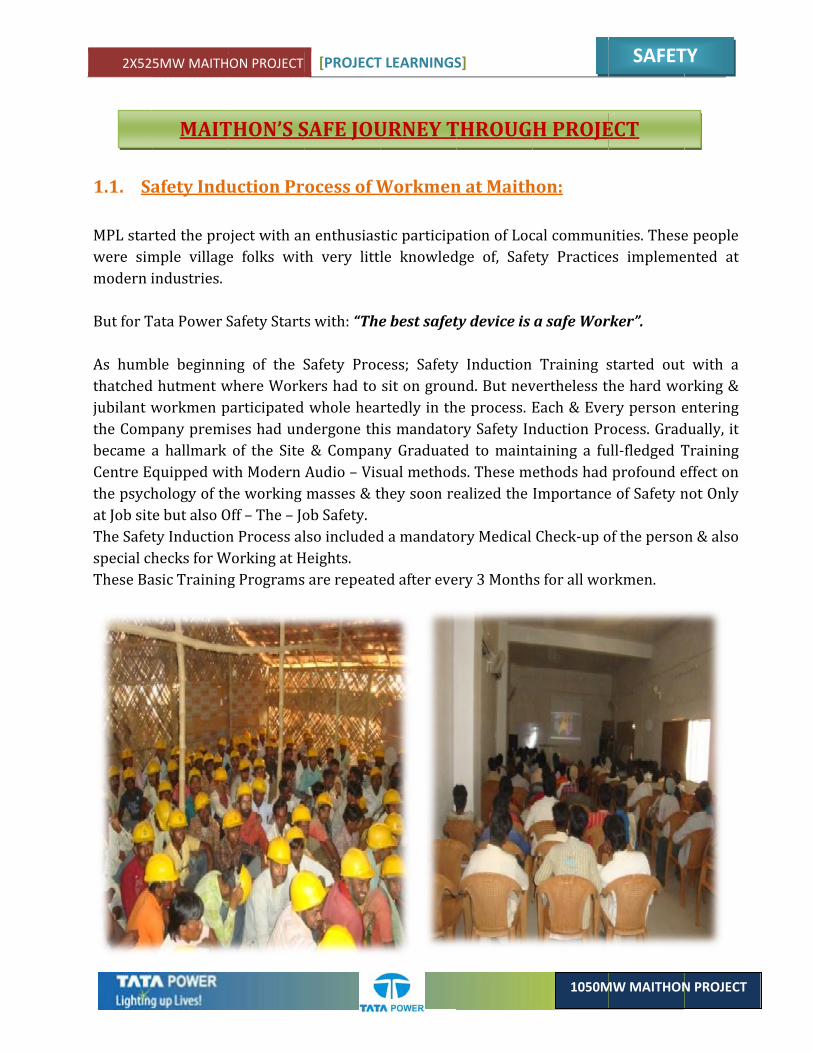
1.1. Sa MPL starwere simmodern i But for T As humbthatchedjubilant wthe Compbecame aCentre Ethe psychat Job sitThe Safetspecial chThese Ba
5MW MAITH
MAIT
afety Indu
rted the promple villageindustries.
Tata Power S
ble beginnid hutment wworkmen ppany premia hallmark quipped wihology of thte but also Oty Inductionhecks for Wasic Training
ON PROJECT
THON’S S
uction Pr
oject with ane folks wit
Safety Start
ng of the Swhere Workparticipatedises had unof the Siteith Modern he working Off – The – Jon Process alWorking at Hg Programs
[PROJECT
SAFE JOU
ocess of W
n enthusiasth very littl
s with: “The
Safety Prockers had to whole headergone th & CompanAudio – Vismasses & tob Safety. lso includedHeights. s are repeate
T LEARNINGS
URNEY T
Workmen
tic participale knowled
e best safet
cess; Safetysit on grourtedly in this mandatony Graduatesual methodthey soon re
d a mandato
ed after eve
S]
THROUG
n at Maith
ation of Locdge of, Safe
ty device is
y Induction nd. But nevhe process. Ery Safety Ined to maintds. These mealized the
ory Medical
ery 3 Month
1050M
H PROJE
hon:
cal communety Practice
a safe Wor
Training svertheless tEach & Evenduction Prtaining a fuethods had Importance
Check‐up o
hs for all wo
SAFET
MW MAITHON
ECT
nities. Thesees impleme
rker”.
started outhe hard woery person erocess. Gradull‐fledged Tprofound ee of Safety n
of the perso
rkmen.
TY
N PROJECT
e people ented at
t with a orking & entering dually, it Training effect on not Only
n & also

2X525MW MAITHON PROJECT [PROJECT LEARNINGS]
SAFETY
1050MW MAITHON PROJECT
1.2. Weekly Contractor Field Safety Audit (CFSA):
Contractor field safety audit is conducted by MPL Safety Department on a weekly basis. CFSA is used as a tool to review the safety management at MPL. CFSA is conducted in presence of all Stake holders’ ‐ Line engineers/Safety officers with TATA Power Line Engineers/Safety officers of respective area. CFSA is conducted on every Monday & Tuesday in the first shift and all observations are presented in Thursday meeting with all stake holders’ Top Leadership at site. The meeting being headed by Tata Power Site leadership takes Cognizance of all the violations & recommends suitable action. This strategy of Safety being Top Driven & enthusiastic participation of ALL leads to the creation of an Intrinsically Safe Work Site.
1.3. Training, Awareness and Motivational Programmes:
To boost the morale of people working at MPL site
• Organizing safety weeks, seminars and exhibitions, Essay Competitions, Contests, and Plays & Songs on Safety themes by MPL & all contractors .
• Display of banners and distribution of pamphlets on Safety Themes. Printing of calendars, stickers, posters containing Safety measures.
• Organizing workshop cum training programs on Safety management, Safety regulation and planning.
• Safety March. • Live demos by experts. • Public Address system • Video shows in workers colony at night
2X525MW MAITHON PROJECT [PROJECT LEARNINGS]
SAFETY
1050MW MAITHON PROJECT
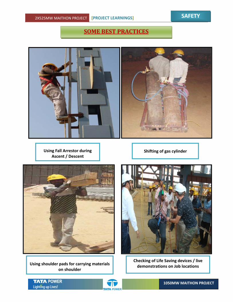
SOME BEST PRACTICES
Using Fall Arrestor during Ascent / Descent
Shifting of gas cylinder
Using shoulder pads for carrying materials on shoulder
Checking of Life Saving devices / live demonstrations on Job locations
2X525MW MAITHON PROJECT [PROJECT LEARNINGS]
SAFETY
1050MW MAITHON PROJECT
‘
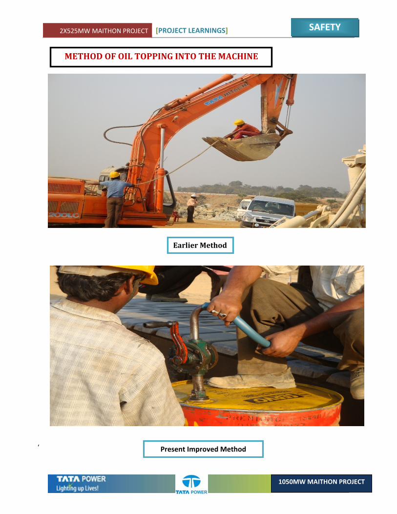
METHOD OF OIL TOPPING INTO THE MACHINE
Earlier Method
Present Improved Method
2X525MW MAITHON PROJECT [PROJECT LEARNINGS]
SAFETY
1050MW MAITHON PROJECT
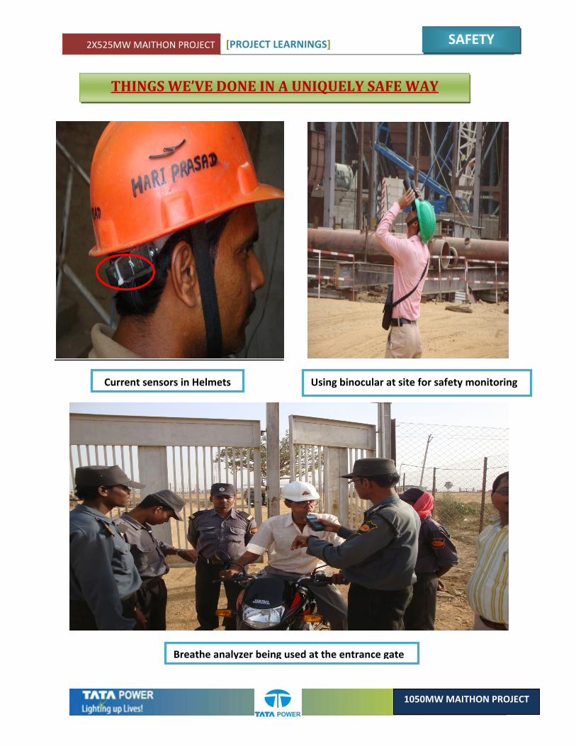
THINGS WE’VE DONE IN A UNIQUELY SAFE WAY
Current sensors in Helmets Using binocular at site for safety monitoring
Breathe analyzer being used at the entrance gate
2X525MW MAITHON PROJECT [PROJECT LEARNINGS]
SAFETY
1050MW MAITHON PROJECT
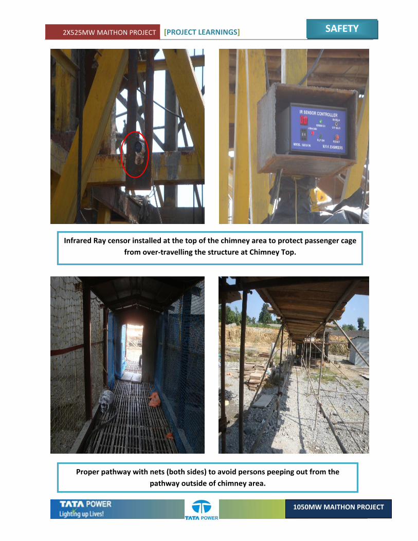
Infrared Ray censor installed at the top of the chimney area to protect passenger cage from over‐travelling the structure at Chimney Top.
Proper pathway with nets (both sides) to avoid persons peeping out from the pathway outside of chimney area.
2X525MW MAITHON PROJECT [PROJECT LEARNINGS]
SAFETY
1050MW MAITHON PROJECT
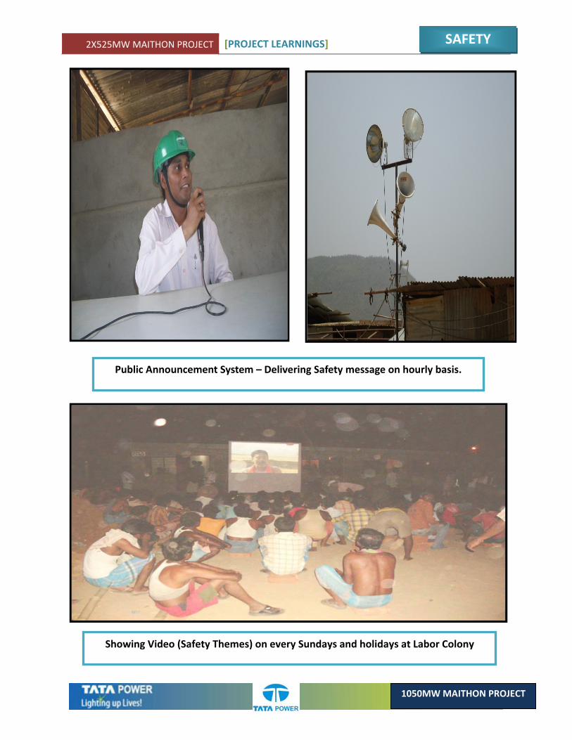
Public Announcement System – Delivering Safety message on hourly basis.
Showing Video (Safety Themes) on every Sundays and holidays at Labor Colony
2X525MW MAITHON PROJECT [PROJECT LEARNINGS]
SAFETY
1050MW MAITHON PROJECT
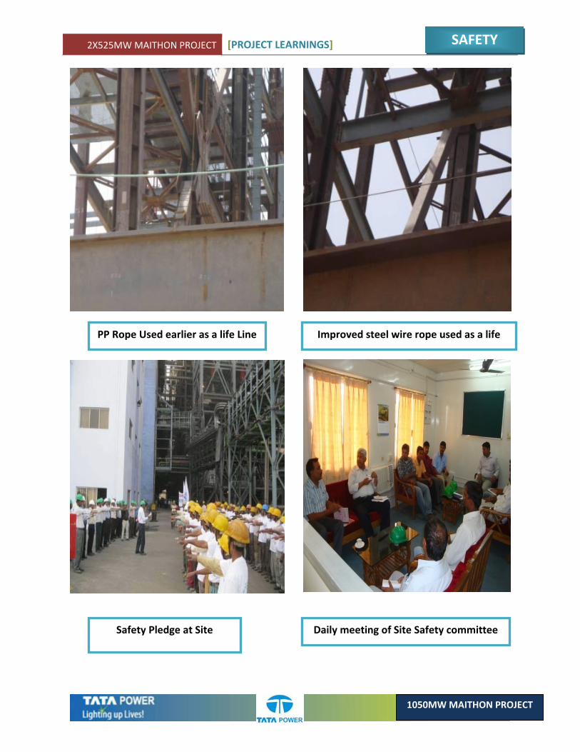
PP Rope Used earlier as a life Line Improved steel wire rope used as a life
Safety Pledge at Site Daily meeting of Site Safety committee
CHAPTER 2DESIGN

2X525MW MAITHON PROJECT [PROJECT LEARNINGS]
DESIGN
1050MW MAITHON PROJECT
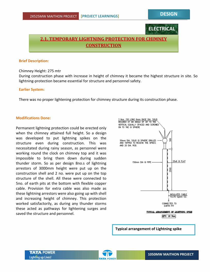
Brief Description: Chimney Height: 275 mtr During construction phase with increase in height of chimney it became the highest structure in site. So lightning‐protection became essential for structure and personnel safety.
Earlier System: There was no proper lightening protection for chimney structure during its construction phase.
Modifications Done: Permanent lightning protection could be erected only when the chimney attained full height. So a design was developed to put lightning spikes on the structure even during construction. This was necessitated during rainy season, as personnel were working round the clock on chimney top and it was impossible to bring them down during sudden thunder storm. So as per design 8no.s of lightning arrestors of 3000mm height were put up on the construction shell and 2 no. were put up on the top structure of the shell. All these were connected to 5no. of earth pits at the bottom with flexible copper cable. Provision for extra cable was also made as these lightning arrestors were also going up with shell and increasing height of chimney. This protection worked satisfactorily, as during any thunder storms these acted as pathways for lightening surges and saved the structure and personnel.
2.1. TEMPORARY LIGHTNING PROTECTION FOR CHIMNEY CONSTRUCTION
Typical arrangement of Lightning spike
ELECTRICAL
2X525MW MAITHON PROJECT [PROJECT LEARNINGS]
DESIGN
1050MW MAITHON PROJECT
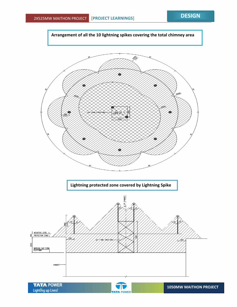
Arrangement of all the 10 lightning spikes covering the total chimney area
Lightning protected zone covered by Lightning Spike
2X525MW MAITHON PROJECT [PROJECT LEARNINGS]
DESIGN
1050MW MAITHON PROJECT
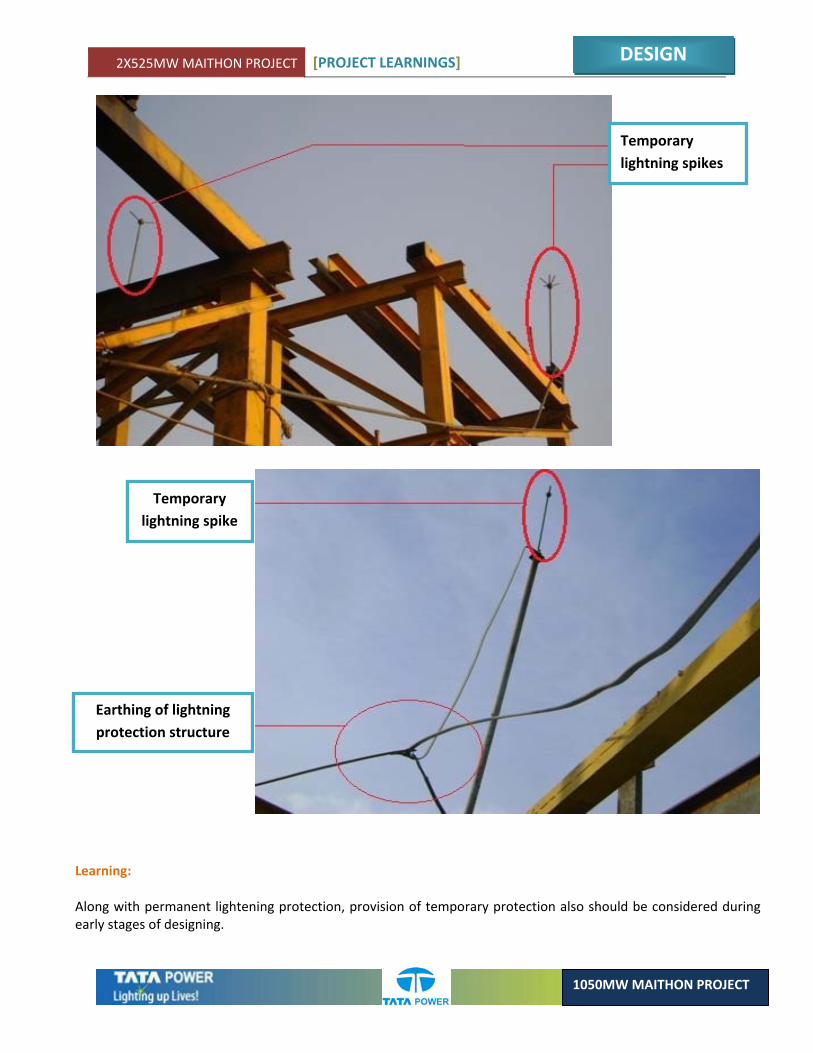
Learning: Along with permanent lightening protection, provision of temporary protection also should be considered during early stages of designing.
Temporary lightning spikes
Temporary lightning spike
Earthing of lightning protection structure
2X525MW MAITHON PROJECT [PROJECT LEARNINGS]
DESIGN
1050MW MAITHON PROJECT
2.2. CABLE PATHWAY EXTRA REQUIREMENT BETWEEN 400KV SWITCHYARD AND TG BUILDING
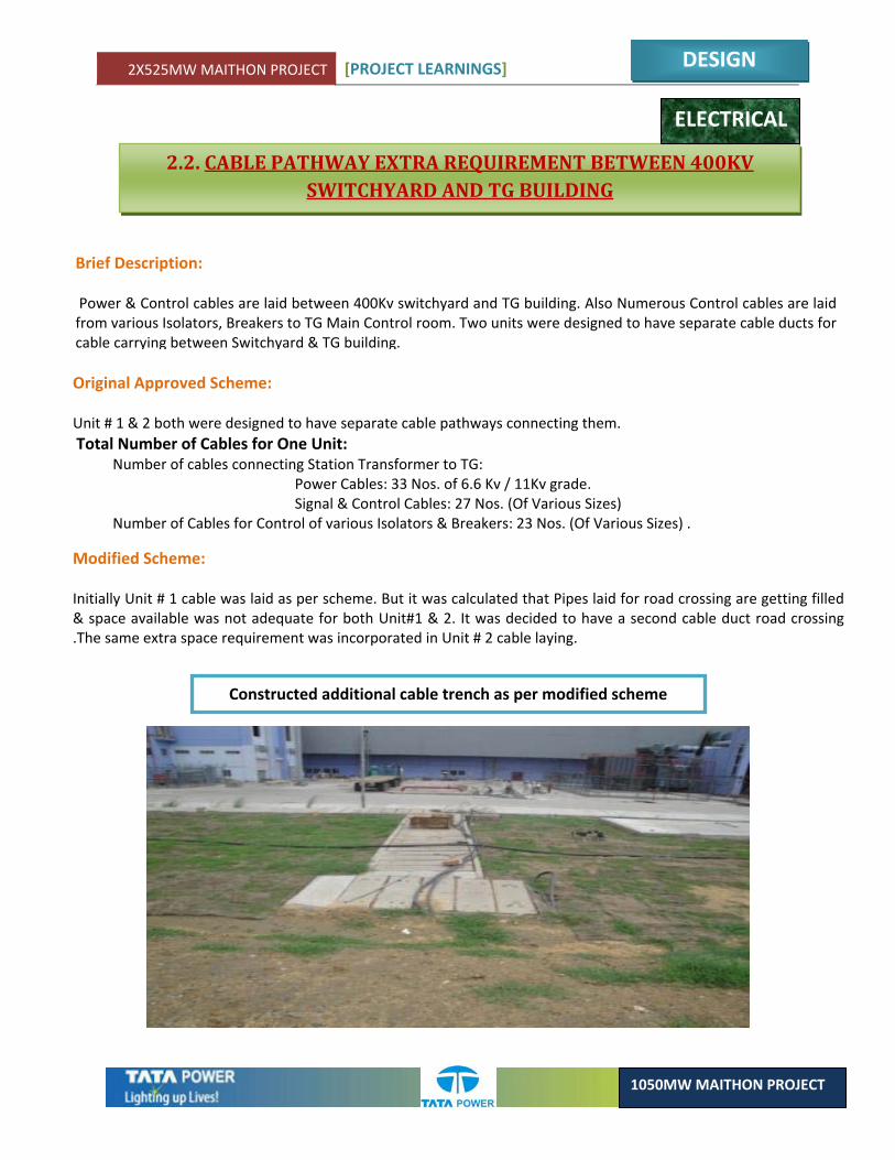
Brief Description: Power & Control cables are laid between 400Kv switchyard and TG building. Also Numerous Control cables are laid from various Isolators, Breakers to TG Main Control room. Two units were designed to have separate cable ducts for cable carrying between Switchyard & TG building.
Original Approved Scheme: Unit # 1 & 2 both were designed to have separate cable pathways connecting them. Total Number of Cables for One Unit: Number of cables connecting Station Transformer to TG: Power Cables: 33 Nos. of 6.6 Kv / 11Kv grade. Signal & Control Cables: 27 Nos. (Of Various Sizes) Number of Cables for Control of various Isolators & Breakers: 23 Nos. (Of Various Sizes) .
Modified Scheme: Initially Unit # 1 cable was laid as per scheme. But it was calculated that Pipes laid for road crossing are getting filled & space available was not adequate for both Unit#1 & 2. It was decided to have a second cable duct road crossing .The same extra space requirement was incorporated in Unit # 2 cable laying.
ELECTRICAL
Constructed additional cable trench as per modified scheme

2X525MW MAITHON PROJECT [PROJECT LEARNINGS]
DESIGN
1050MW MAITHON PROJECT
New Cable Duct Road Crossing
Learning:
3. Total number of cables need to be calculated and accordingly space/area to be designed. 4. Some percentage of extra space to be provided for future and other LAN/telephone cables.
New Cable Path way Constructed in Switchyard
2X525MW MAITHON PROJECT [PROJECT LEARNINGS]
DESIGN
1050MW MAITHON PROJECT
2. 3. CORRIDOR FOR CONSTRUCTION POWER SUPPLY
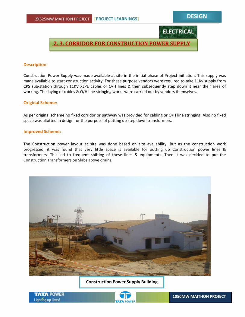
Description: Construction Power Supply was made available at site in the initial phase of Project initiation. This supply was made available to start construction activity. For these purpose vendors were required to take 11Kv supply from CPS sub‐station through 11KV XLPE cables or O/H lines & then subsequently step down it near their area of working. The laying of cables & O/H line stringing works were carried out by vendors themselves. Original Scheme: As per original scheme no fixed corridor or pathway was provided for cabling or O/H line stringing. Also no fixed space was allotted in design for the purpose of putting up step down transformers. Improved Scheme: The Construction power layout at site was done based on site availability. But as the construction work progressed, it was found that very little space is available for putting up Construction power lines & transformers. This led to frequent shifting of these lines & equipments. Then it was decided to put the Construction Transformers on Slabs above drains.
ELECTRICAL
Construction Power Supply Building
2X525MW MAITHON PROJECT [PROJECT LEARNINGS]
DESIGN
1050MW MAITHON PROJECT
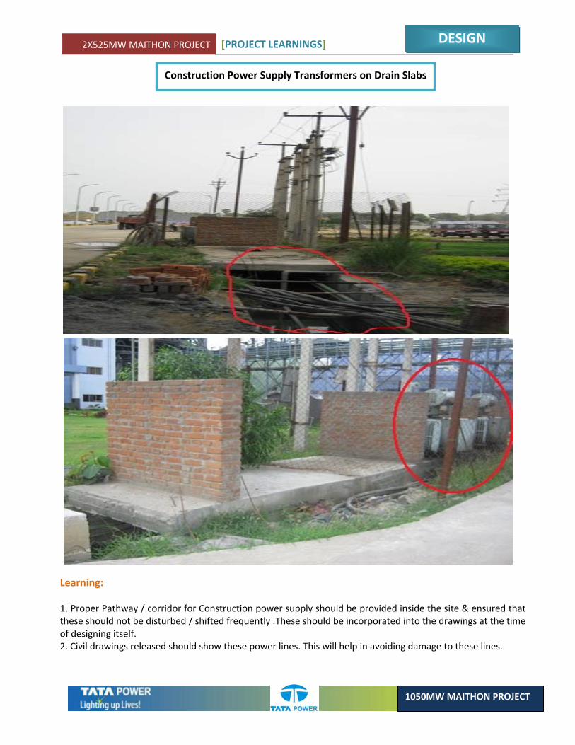
Construction Power Supply Transformers on Drain Slabs
Learning: 1. Proper Pathway / corridor for Construction power supply should be provided inside the site & ensured that these should not be disturbed / shifted frequently .These should be incorporated into the drawings at the time of designing itself. 2. Civil drawings released should show these power lines. This will help in avoiding damage to these lines.
2X525MW MAITHON PROJECT [PROJECT LEARNINGS]
DESIGN
1050MW MAITHON PROJECT
Description:
The Three Nos. of Single Phase Generator Transformers are installed at TG end & their 21.5 Kv side are connected with Generator by Bus ducts. The 400Kv outgoing of Generator Transformer are connected to the switchyard by O/H conductors. These conductors are connected to GT – High Voltage bushing by conductor droppings from the main conductor .The main conductor is then end stringed at TG A – row ( Above AC – duct sheeting ) with insulators .
Original Scheme:
As per the approved drawings the total distance between 400Kv live part & AC duct sheeting was 4910mm. This was considered quiet low taking into consideration various factors like swings during storm etc. Also during heavy rains this might have lead to some flashover causing heavy damage.
Improved Scheme:
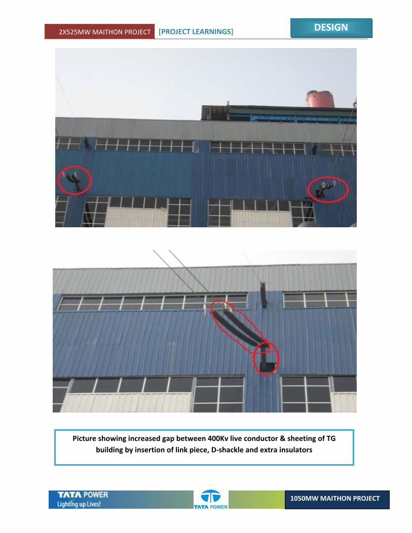
To increase this gap between 400Kv live conductor & sheeting of TG building; it was decided to add some extra fittings to these conductors at TG end. For achieving this; following items were added:
1. Link Piece: 750mm length. 2. D – Shackle: 2 Nos. : 180mm length increase. 3. Disc Insulator: 8 Nos. : 145 X 8 = 1160mm.
This led to a total increase in gap of 2090mm. This modification was approved & implemented at site & same adopted for Unit # 2. This enhanced the Safety of all the equipments concerned.
ELECTRICAL
2. 4. 400 KV OUTGOING CONDUCTORS STRINGING AT TG END (A – ROW)
2X525MW MAITHON PROJECT [PROJECT LEARNINGS]
DESIGN
1050MW MAITHON PROJECT
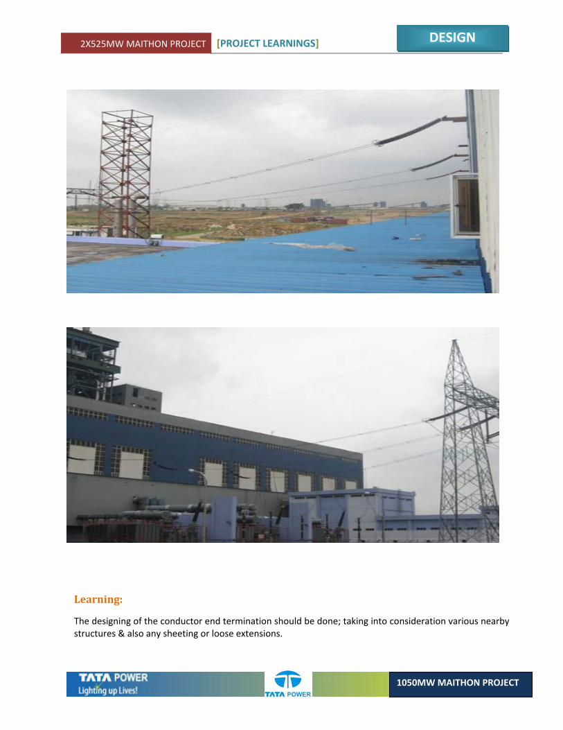
Picture showing increased gap between 400Kv live conductor & sheeting of TG building by insertion of link piece, D‐shackle and extra insulators
2X525MW MAITHON PROJECT [PROJECT LEARNINGS]
DESIGN
1050MW MAITHON PROJECT
Learning:
The designing of the conductor end termination should be done; taking into consideration various nearby structures & also any sheeting or loose extensions.
2X525MW MAITHON PROJECT [PROJECT LEARNINGS]
DESIGN
1050MW MAITHON PROJECT
2.5. MODIFICATION IN TRIP LOGIC FOR RESRTRICTED EARTH FAULT IN ASH HANDLING PLANT
Brief description:
• Ash handling plant is having two type switchgear. • 6.6KV: Two incomer comes from TG side station Transformer1&2 and other are bus coupler and
outgoing feeder which are for higher more rating (rating more than 200KW). • 415V: 415V switchgear are having two incomer(415),bus coupler and outgoing feeders.
Existing Scheme:
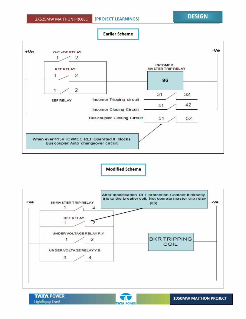
• REF protection operates during transformer winding fault. • As per design, REF protection contact will directly trip the master trip relay (86) which will open
incomer1&2. • In case REF operates, it will operate 86 lock out relay and it will block closing of bus coupler
breaker.
Modified Scheme:
• As per modified scheme REF relay contact has been removed to operate 86 relay. • REF relay contact has been directly wired to trip breaker (without 86 relay)
Learning:
During Design stage care should be taken to provide uniform scheme for protection system, also system reliability should be considered.
ELECTRICAL
2X525MW MAITHON PROJECT [PROJECT LEARNINGS]
DESIGN
1050MW MAITHON PROJECT
Earlier Scheme
Modified Scheme

2X525MW MAITHON PROJECT [PROJECT LEARNINGS]
DESIGN
1050MW MAITHON PROJECT
2.6. MODIFICATION IN EARTH FAULT RELAY FOR PLANT WATER SYSTEM (TRANSFORMER FEEDER)
Brief Description:
Plant water system is having two 6.6KV incomer and bus coupler which takes care entire load of Plant Water System.
Earlier Scheme:
• All outgoing transformer Feeder’s are having 2 nos. of Over Current + Earth Fault protection Relay (Argus 1 & 2). Argus‐1 relay does not have any E/F protection as per scheme.
• Argus‐1 relay is connected to CT which are having lower primary current. No CT connection was wired to enable E/F protection.
Earlier Scheme
ELECTRICAL
2X525MW MAITHON PROJECT [PROJECT LEARNINGS]
DESIGN
1050MW MAITHON PROJECT
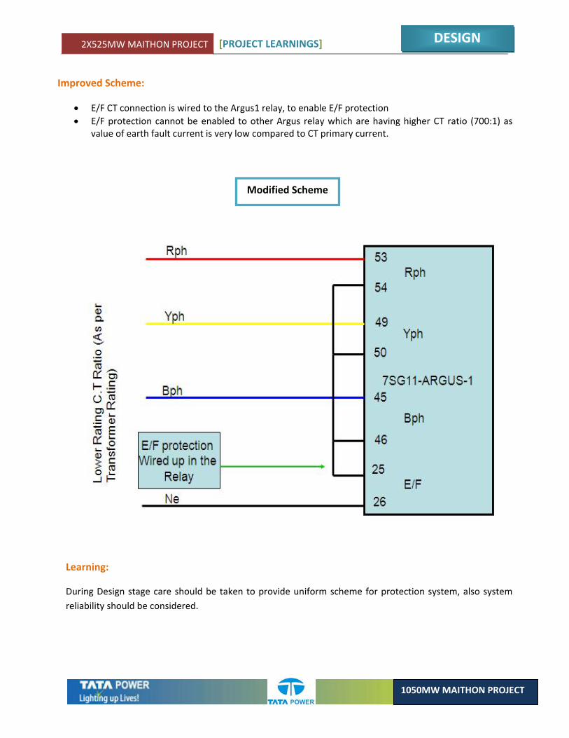
Improved Scheme:
• E/F CT connection is wired to the Argus1 relay, to enable E/F protection • E/F protection cannot be enabled to other Argus relay which are having higher CT ratio (700:1) as
value of earth fault current is very low compared to CT primary current.
Modified Scheme
Learning:
During Design stage care should be taken to provide uniform scheme for protection system, also system reliability should be considered.
2X525MW MAITHON PROJECT [PROJECT LEARNINGS]
DESIGN
1050MW MAITHON PROJECT
2.7. POTENTIAL TRANSFORMER CIRCUIT MODIFICATION FOR LINE DISTANCE PROTECTION
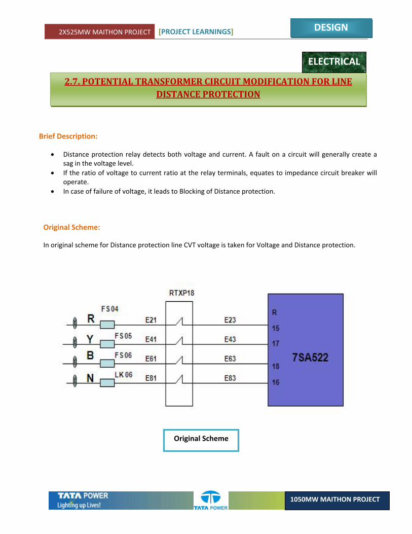
Brief Description:
• Distance protection relay detects both voltage and current. A fault on a circuit will generally create a sag in the voltage level.
• If the ratio of voltage to current ratio at the relay terminals, equates to impedance circuit breaker will operate.
• In case of failure of voltage, it leads to Blocking of Distance protection.
Original Scheme:
In original scheme for Distance protection line CVT voltage is taken for Voltage and Distance protection.
ELECTRICAL
Original Scheme
2X525MW MAITHON PROJECT [PROJECT LEARNINGS]
DESIGN
1050MW MAITHON PROJECT
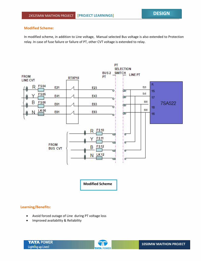
Modified Scheme:
In modified scheme, in addition to Line voltage, Manual selected Bus voltage is also extended to Protection relay. In case of fuse failure or failure of PT, other CVT voltage is extended to relay.
Modified Scheme
Learning/Benefits:
• Avoid forced outage of Line during PT voltage loss • Improved availability & Reliability
2X525MW MAITHON PROJECT [PROJECT LEARNINGS]
DESIGN
1050MW MAITHON PROJECT
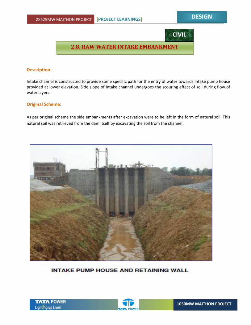
2.8. RAW WATER INTAKE EMBANKMENT
Description: Intake channel is constructed to provide some specific path for the entry of water towards Intake pump house provided at lower elevation. Side slope of Intake channel undergoes the scouring effect of soil during flow of water layers. Original Scheme: As per original scheme the side embankments after excavation were to be left in the form of natural soil. This natural soil was retrieved from the dam itself by excavating the soil from the channel.
CIVIL
2X525MW MAITHON PROJECT [PROJECT LEARNINGS]
DESIGN
1050MW MAITHON PROJECT
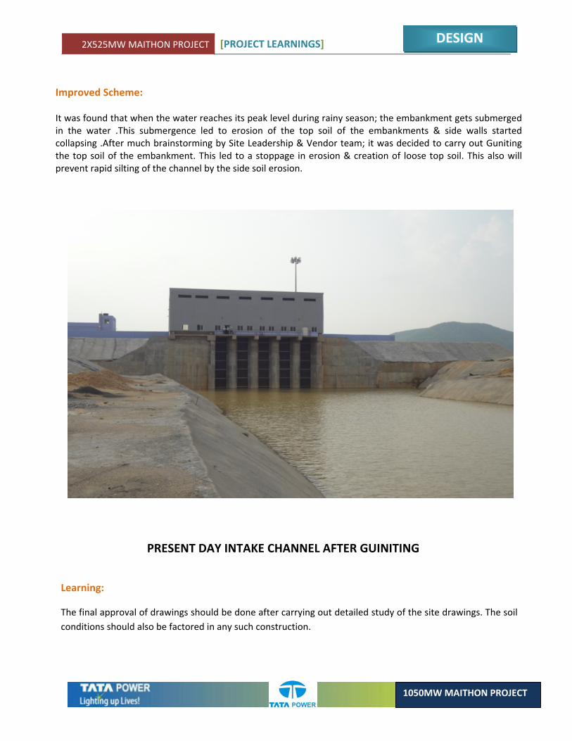
Improved Scheme: It was found that when the water reaches its peak level during rainy season; the embankment gets submerged in the water .This submergence led to erosion of the top soil of the embankments & side walls started collapsing .After much brainstorming by Site Leadership & Vendor team; it was decided to carry out Guniting the top soil of the embankment. This led to a stoppage in erosion & creation of loose top soil. This also will prevent rapid silting of the channel by the side soil erosion.
Learning:
The final approval of drawings should be done after carrying out detailed study of the site drawings. The soil conditions should also be factored in any such construction.
PRESENT DAY INTAKE CHANNEL AFTER GUINITING
2X525MW MAITHON PROJECT [PROJECT LEARNINGS]
DESIGN
1050MW MAITHON PROJECT
2.9. MODIFICATION OF CURRENT CIRCUIT FOR LBB PROTECTION
ELECTRICAL
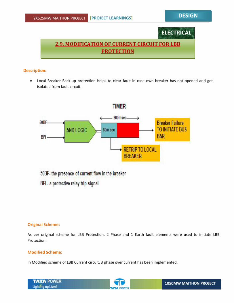
Description:
• Local Breaker Back‐up protection helps to clear fault in case own breaker has not opened and get isolated from fault circuit.
Original Scheme:
As per original scheme for LBB Protection, 2 Phase and 1 Earth fault elements were used to initiate LBB Protection.
Modified Scheme:
In Modified scheme of LBB Current circuit, 3 phase over current has been implemented.
2X525MW MAITHON PROJECT [PROJECT LEARNINGS]
DESIGN
1050MW MAITHON PROJECT
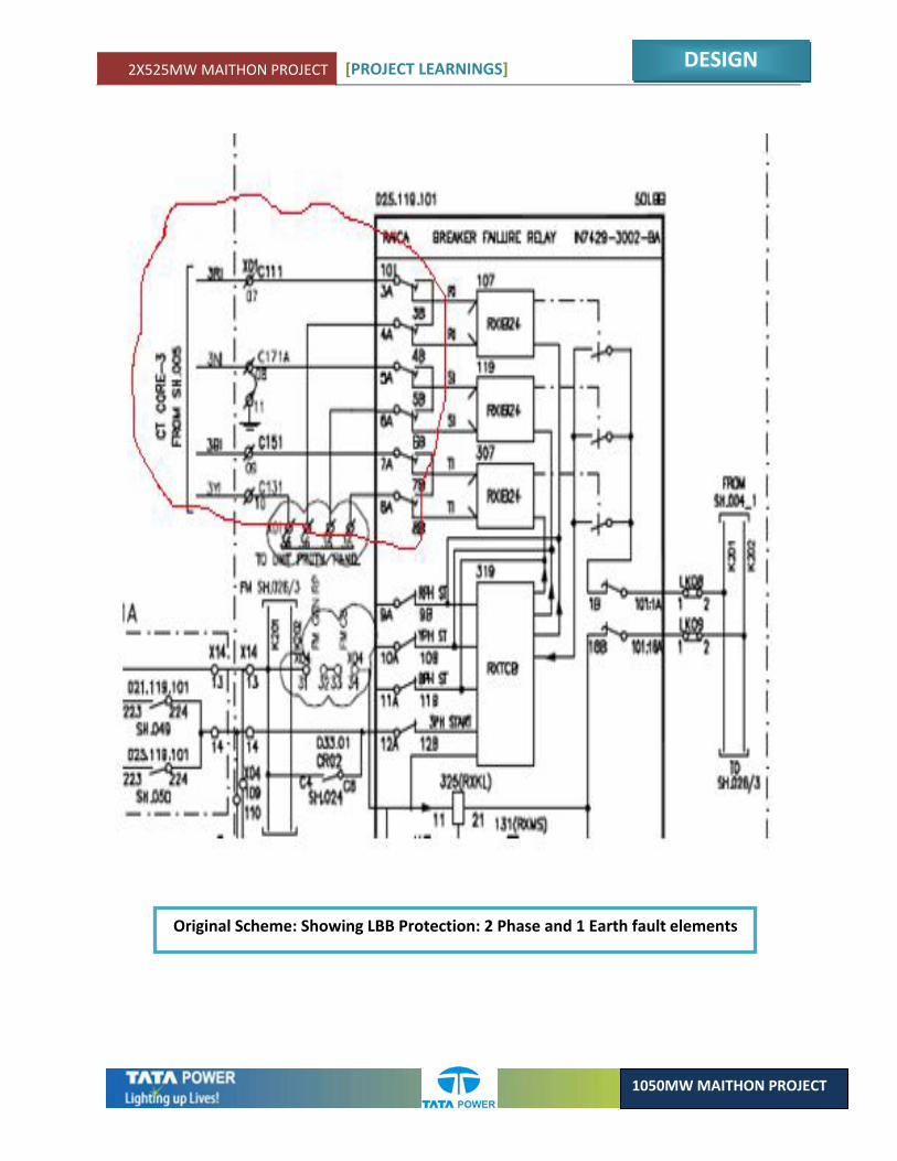
Original Scheme: Showing LBB Protection: 2 Phase and 1 Earth fault elements
2X525MW MAITHON PROJECT [PROJECT LEARNINGS]
DESIGN
1050MW MAITHON PROJECT
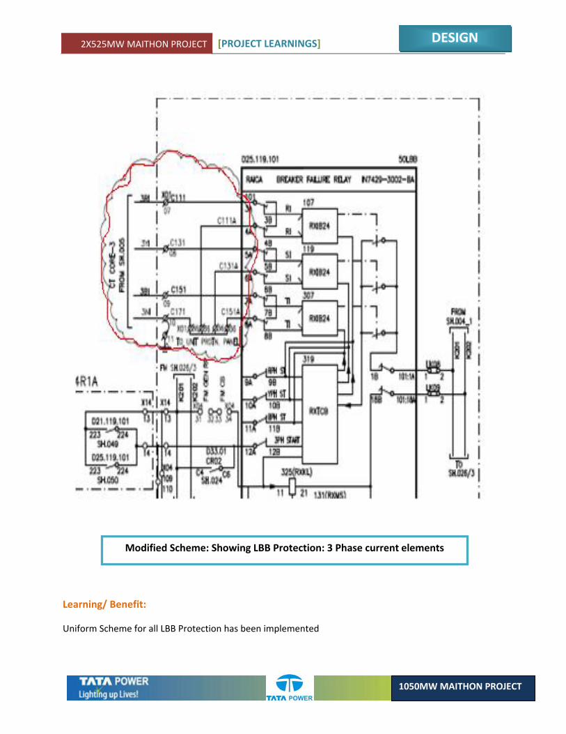
Modified Scheme: Showing LBB Protection: 3 Phase current elements
Learning/ Benefit:
Uniform Scheme for all LBB Protection has been implemented
2X525MW MAITHON PROJECT [PROJECT LEARNINGS]
DESIGN
1050MW MAITHON PROJECT
2.10. GENERATOR PROTECTION TRIP CIRCUIT SUPERVISION MODIFICATION
ELECTRICAL
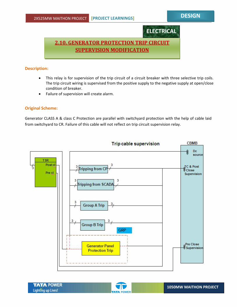
Description:
• This relay is for supervision of the trip circuit of a circuit breaker with three selective trip coils. The trip circuit wiring is supervised from the positive supply to the negative supply at open/close condition of breaker.
• Failure of supervision will create alarm.
Original Scheme:
Generator CLASS A & class C Protection are parallel with switchyard protection with the help of cable laid from switchyard to CR. Failure of this cable will not reflect on trip circuit supervision relay.

2X525MW MAITHON PROJECT [PROJECT LEARNINGS]
DESIGN
1050MW MAITHON PROJECT
Modified Scheme :
To ensure the healthiness of this cable. GRP Class A & Class C tripping circuit has been made in series with trip circuit supervision. Failure of this cable will Energies Trip circuit Failure Relay.
Learning/Benefits:
• Improved Reliability
• Immediate detection of defect
2X525MW MAITHON PROJECT [PROJECT LEARNINGS]
DESIGN
1050MW MAITHON PROJECT
2.11. PROVISION OF RAMP FOR COAL FEEDING IN TRACK HOPPER
CIVIL
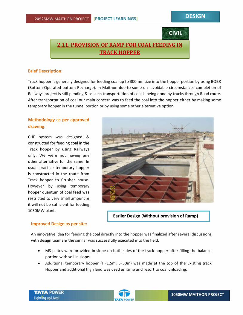
Brief Description:
Track hopper is generally designed for feeding coal up to 300mm size into the hopper portion by using BOBR (Bottom Operated bottom Recharge). In Maithon due to some un‐ avoidable circumstances completion of Railways project is still pending & as such transportation of coal is being done by trucks through Road route. After transportation of coal our main concern was to feed the coal into the hopper either by making some temporary hopper in the tunnel portion or by using some other alternative option.
Methodology as per approved drawing:
CHP system was designed & constructed for feeding coal in the Track hopper by using Railways only. We were not having any other alternative for the same. In usual practice temporary hopper is constructed in the route from Track hopper to Crusher house. However by using temporary hopper quantum of coal feed was restricted to very small amount & it will not be sufficient for feeding 1050MW plant.
Improved Design as per site:
An innovative idea for feeding the coal directly into the hopper was finalized after several discussions with design teams & the similar was successfully executed into the field.
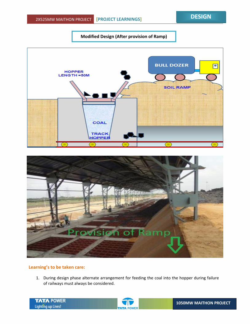
• MS plates were provided in slope on both sides of the track hopper after filling the balance portion with soil in slope.
• Additional temporary hopper (H=1.5m, L=50m) was made at the top of the Existing track Hopper and additional high land was used as ramp and resort to coal unloading.
Earlier Design (Without provision of Ramp)
2X525MW MAITHON PROJECT [PROJECT LEARNINGS]
DESIGN
1050MW MAITHON PROJECT
Modified Design (After provision of Ramp)
Learning’s to be taken care:
1. During design phase alternate arrangement for feeding the coal into the hopper during failure of railways must always be considered.
2X525MW MAITHON PROJECT [PROJECT LEARNINGS]
DESIGN
1050MW MAITHON PROJECT
2.12. PROVISION OF CONCRETE ENCASING FOR CW PIPE LINE
CIVIL
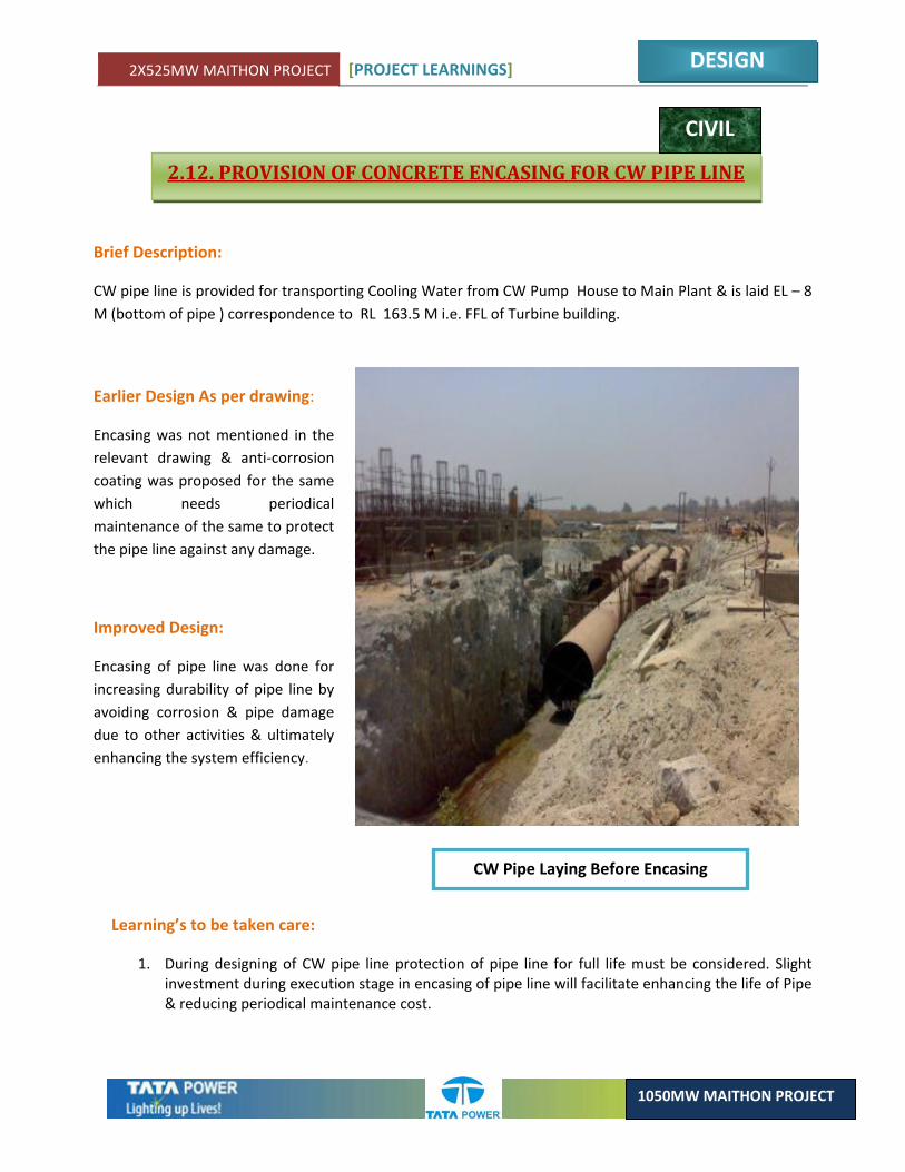
Brief Description:
CW pipe line is provided for transporting Cooling Water from CW Pump House to Main Plant & is laid EL – 8 M (bottom of pipe ) correspondence to RL 163.5 M i.e. FFL of Turbine building.
Earlier Design As per drawing:
Encasing was not mentioned in the relevant drawing & anti‐corrosion coating was proposed for the same which needs periodical maintenance of the same to protect the pipe line against any damage.
Improved Design:
Encasing of pipe line was done for increasing durability of pipe line by avoiding corrosion & pipe damage due to other activities & ultimately enhancing the system efficiency.
Learning’s to be taken care:
1. During designing of CW pipe line protection of pipe line for full life must be considered. Slight investment during execution stage in encasing of pipe line will facilitate enhancing the life of Pipe & reducing periodical maintenance cost.
CW Pipe Laying Before Encasing
2X525MW MAITHON PROJECT [PROJECT LEARNINGS]
DESIGN
1050MW MAITHON PROJECT
2.13. PROVISION OF DRILLED MS FLAT FOR FIXING OF WOODEN DOOR FRAMES IN STAFF COLONY
CIVIL
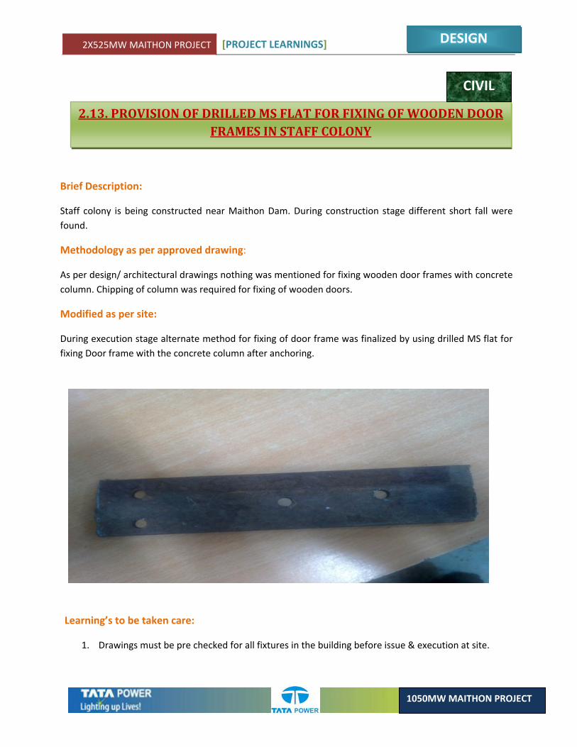
Brief Description:
Staff colony is being constructed near Maithon Dam. During construction stage different short fall were found.
Methodology as per approved drawing:
As per design/ architectural drawings nothing was mentioned for fixing wooden door frames with concrete column. Chipping of column was required for fixing of wooden doors.
Modified as per site:
During execution stage alternate method for fixing of door frame was finalized by using drilled MS flat for fixing Door frame with the concrete column after anchoring.
Learning’s to be taken care:
1. Drawings must be pre checked for all fixtures in the building before issue & execution at site.
2X525MW MAITHON PROJECT [PROJECT LEARNINGS]
DESIGN
1050MW MAITHON PROJECT
2.14. PORTICO OF TECHNICAL BUILDING
CIVIL
Brief Description:
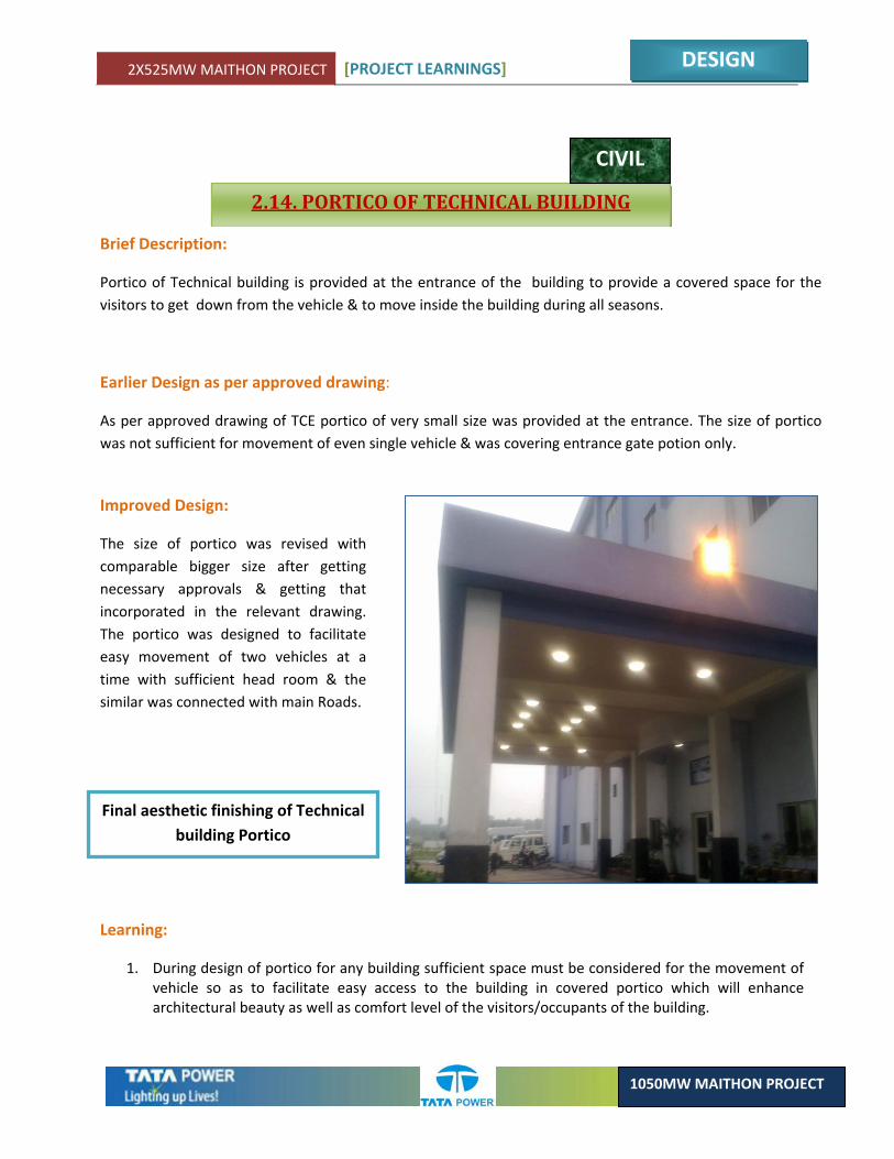
Portico of Technical building is provided at the entrance of the building to provide a covered space for the visitors to get down from the vehicle & to move inside the building during all seasons.
Earlier Design as per approved drawing:
As per approved drawing of TCE portico of very small size was provided at the entrance. The size of portico was not sufficient for movement of even single vehicle & was covering entrance gate potion only.
Final aesthetic finishing of Technical building Portico
Learning:
1. During design of portico for any building sufficient space must be considered for the movement of vehicle so as to facilitate easy access to the building in covered portico which will enhance architectural beauty as well as comfort level of the visitors/occupants of the building.
Improved Design:
The size of portico was revised with comparable bigger size after getting necessary approvals & getting that incorporated in the relevant drawing. The portico was designed to facilitate easy movement of two vehicles at a time with sufficient head room & the similar was connected with main Roads.
2X525MW MAITHON PROJECT [PROJECT LEARNINGS]
DESIGN
1050MW MAITHON PROJECT
2.15. 6.6KV BUS COUPLER AUTO CHANGE OVER SCHEME FOR COAL HANDLING SYSTEM
ELECTRICAL
Brief Description:
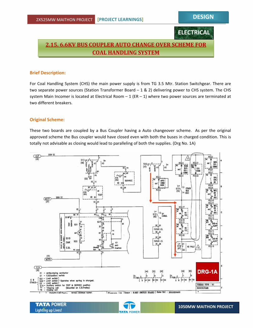
For Coal Handling System (CHS) the main power supply is from TG 3.5 Mtr. Station Switchgear. There are two separate power sources (Station Transformer Board – 1 & 2) delivering power to CHS system. The CHS system Main Incomer is located at Electrical Room – 1 (ER – 1) where two power sources are terminated at two different breakers.
Original Scheme:
These two boards are coupled by a Bus Coupler having a Auto changeover scheme. As per the original approved scheme the Bus coupler would have closed even with both the buses in charged condition. This is totally not advisable as closing would lead to paralleling of both the supplies. (Drg No. 1A)
2X525MW MAITHON PROJECT [PROJECT LEARNINGS]
DESIGN
1050MW MAITHON PROJECT
Improved Scheme:
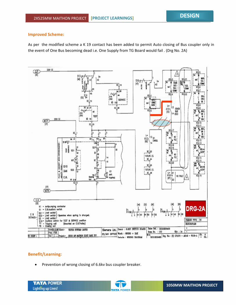
As per the modified scheme a K 19 contact has been added to permit Auto closing of Bus coupler only in the event of One Bus becoming dead i.e. One Supply from TG Board would fail . (Drg No. 2A)
Benefit/Learning:
• Prevention of wrong closing of 6.6kv bus coupler breaker.

2X525MW MAITHON PROJECT [PROJECT LEARNINGS]
DESIGN
1050MW MAITHON PROJECT
2.16. MODIFICATION OF SYNCHRONIZING CIRCUIT DURING CLOSING OF INCOMER AND BUS COUPLER BREAKER FOR 6.6KV ASH
HANDLING SYSTEM
ELECTRICAL
Brief Description:
Refer previous article.
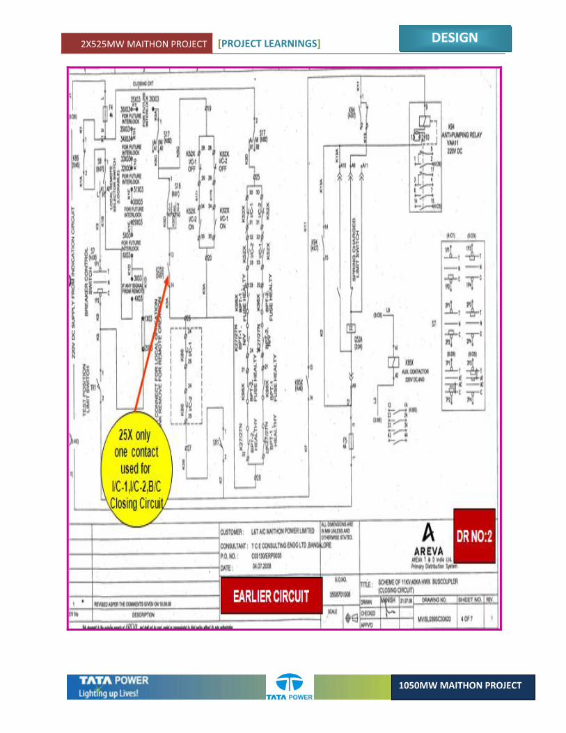
Original Scheme:
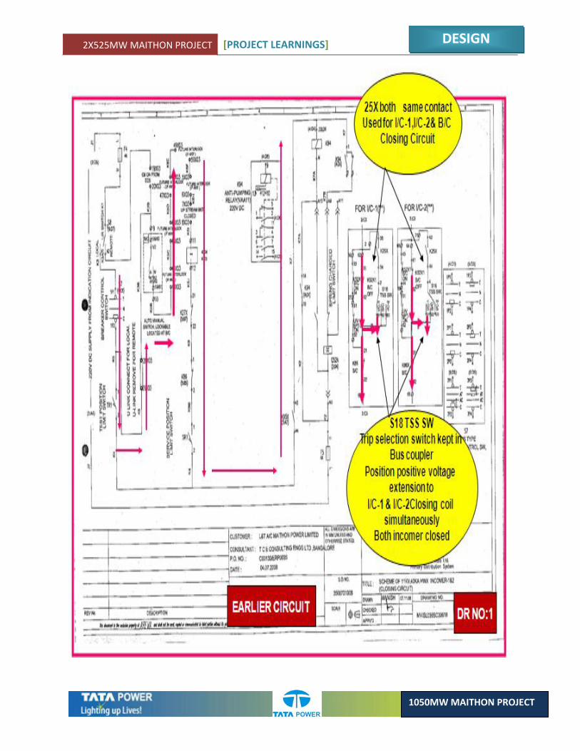
As per original scheme single contact of K25 relay (Synchronizing relay) was used for closing of both incomer & bus coupler breaker for Ash handling system. If S18(TSS) Contact is kept at Bus coupler position one incomer D.C will mix up with other incomer D.C circuit(Ref Drg No:1,2,2A).
2X525MW MAITHON PROJECT [PROJECT LEARNINGS]
DESIGN
1050MW MAITHON PROJECT
2X525MW MAITHON PROJECT [PROJECT LEARNINGS]
DESIGN
1050MW MAITHON PROJECT
2X525MW MAITHON PROJECT [PROJECT LEARNINGS]
DESIGN
1050MW MAITHON PROJECT
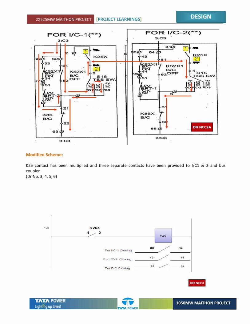
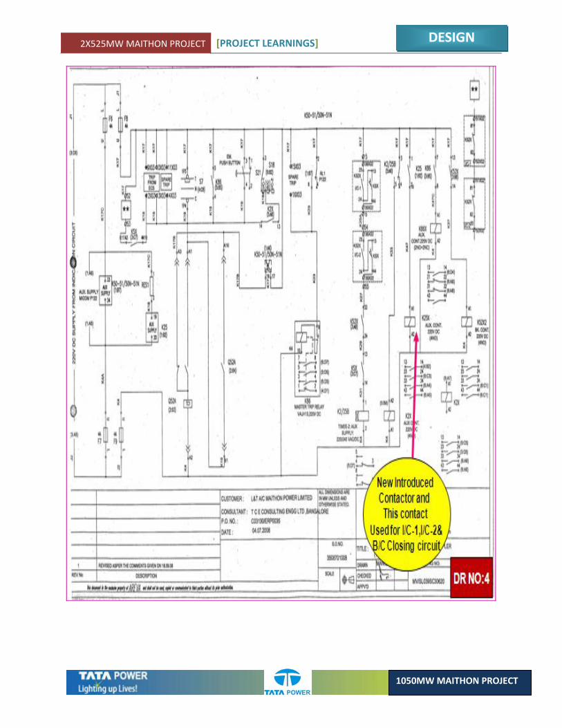
Modified Scheme:
K25 contact has been multiplied and three separate contacts have been provided to I/C1 & 2 and bus coupler. (Dr No. 3, 4, 5, 6)
2X525MW MAITHON PROJECT [PROJECT LEARNINGS]
DESIGN
1050MW MAITHON PROJECT
2X525MW MAITHON PROJECT [PROJECT LEARNINGS]
DESIGN
1050MW MAITHON PROJECT
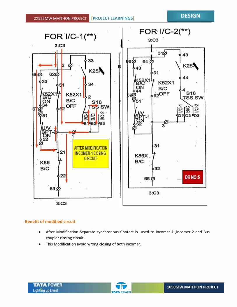
Benefit of modified circuit
• After Modification Separate synchronous Contact is used to Incomer‐1 ,incomer‐2 and Bus coupler closing circuit .
• This Modification avoid wrong closing of both incomer.
2X525MW MAITHON PROJECT [PROJECT LEARNINGS]
DESIGN
1050MW MAITHON PROJECT
2.17. COAL HANDLING PLANT 415V (L.T) BUS COUPLER AUTO CHANGE OVER SCHEME
ELECTRICAL
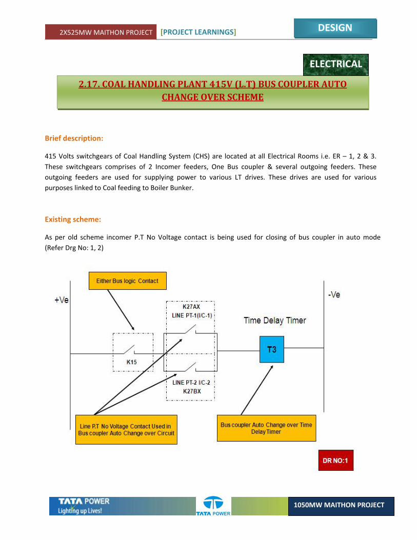
Brief description:
415 Volts switchgears of Coal Handling System (CHS) are located at all Electrical Rooms i.e. ER – 1, 2 & 3. These switchgears comprises of 2 Incomer feeders, One Bus coupler & several outgoing feeders. These outgoing feeders are used for supplying power to various LT drives. These drives are used for various purposes linked to Coal feeding to Boiler Bunker.
Existing scheme:
As per old scheme incomer P.T No Voltage contact is being used for closing of bus coupler in auto mode (Refer Drg No: 1, 2)

2X525MW MAITHON PROJECT [PROJECT LEARNINGS]
DESIGN
1050MW MAITHON PROJECT
2X525MW MAITHON PROJECT [PROJECT LEARNINGS]
DESIGN
1050MW MAITHON PROJECT
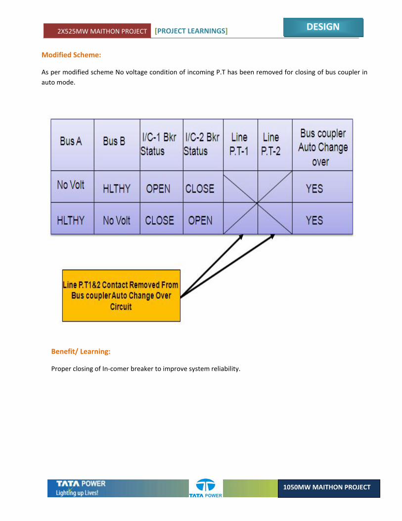
Modified Scheme:
As per modified scheme No voltage condition of incoming P.T has been removed for closing of bus coupler in auto mode.
Benefit/ Learning:
Proper closing of In‐comer breaker to improve system reliability.
2X525MW MAITHON PROJECT [PROJECT LEARNINGS]
DESIGN
1050MW MAITHON PROJECT
2.18. PROPOSAL BASED ON EXPERIENCE OF MAITHON 400 KV SWITCHYARD COMMISSIONING
ELECTRICAL
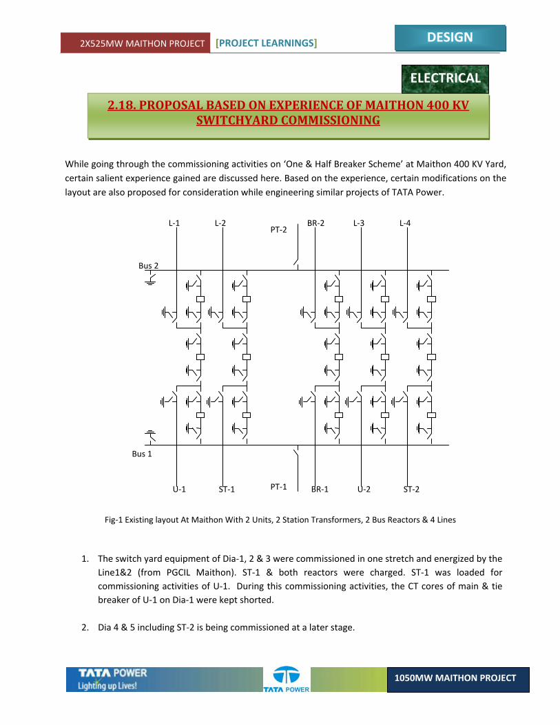
While going through the commissioning activities on ‘One & Half Breaker Scheme’ at Maithon 400 KV Yard, certain salient experience gained are discussed here. Based on the experience, certain modifications on the layout are also proposed for consideration while engineering similar projects of TATA Power.
L‐1
U‐1
L‐2
ST‐1
L‐3
U‐2
L‐4
ST‐2
Bus 2
PT‐2
Bus 1
PT‐1
BR‐2
BR‐1
Fig‐1 Existing layout At Maithon With 2 Units, 2 Station Transformers, 2 Bus Reactors & 4 Lines
1. The switch yard equipment of Dia‐1, 2 & 3 were commissioned in one stretch and energized by the Line1&2 (from PGCIL Maithon). ST‐1 & both reactors were charged. ST‐1 was loaded for commissioning activities of U‐1. During this commissioning activities, the CT cores of main & tie breaker of U‐1 on Dia‐1 were kept shorted.
2. Dia 4 & 5 including ST‐2 is being commissioned at a later stage.
2X525MW MAITHON PROJECT [PROJECT LEARNINGS]
DESIGN
1050MW MAITHON PROJECT
3. Commissioning activities of U‐1 was taken up after ST‐1 was loaded. Following were the salient activities during the commissioning of the U‐1 that involved activities in the yard particularly in dia‐1.
• Cabling & termination of the CT cores to the GRP. Few cables are laid from the dia 1 protection cubicle as the LBB protection of the concerned breaker is on the same CT core.
• Laying & termination of Control wiring of both the breakers from the GRP, ECP & other cubicles.
• Laying & termination of feedback cables from all equipment (breakers & Isolators) of the dia to the GRP & DCS cubicle.
• Stability tests of the CTs.
• Protection, control & feedback trials of the breakers & isolators.
• SCC & OCC.
4. The above commissioning activities were stretched over a period of 2 months. During this period, the two breakers of the Dia 1 were not available for operational use. Hence Line 1 was not available for service on Bus 1.
5. At certain times, the 3rd breaker on the dia was also taken out for trial operation for control & feedback. During this period, the service of Line‐1 was not available, at all, and the station was running, on only one line.
6. In case of any electrical system, the O/H transmission lines are most susceptible to electrical faults. Linking a transmission line to a generator, in the same dia of an 1 & ½ breaker scheme, will always cause a drop in the reliability of the generator, particularly when, for any reason, the main breaker of the unit is kept out and the generator is dependent on the tie breaker.
7. While conducting the commissioning activities on the station as well as the unit, there were multiple occasions when the one of the Busses were taken out. This is primarily for safety reasons, as a charged bus in the vicinity of work was causing sufficient interference and induction. In certain case, the adjacent bay was also de‐energized. During this condition, the system was on one bus, affecting the reliability of the system.
8. Similar situation will appear in future also, while carrying out the routine maintenance activity (annual or otherwise) of various equipments. Hence bus outage will be scheduled on multiple occasions. While the bus outage is not supposed to affect the operation of any equipment, in a 1 & ½ breaker schemes, the reliability of the yard drastically reduces during this period as all the equipment, during this period is banking on only one bus.
2X525MW MAITHON PROJECT [PROJECT LEARNINGS]
DESIGN
1050MW MAITHON PROJECT
L‐1
ST‐1
L‐2
BR‐1
L‐3
BR‐2
L‐4
ST‐2 U‐2 U‐1
Bus 2A Bus 2B
PT‐2
Bus 1A Bus 1B
PT‐1
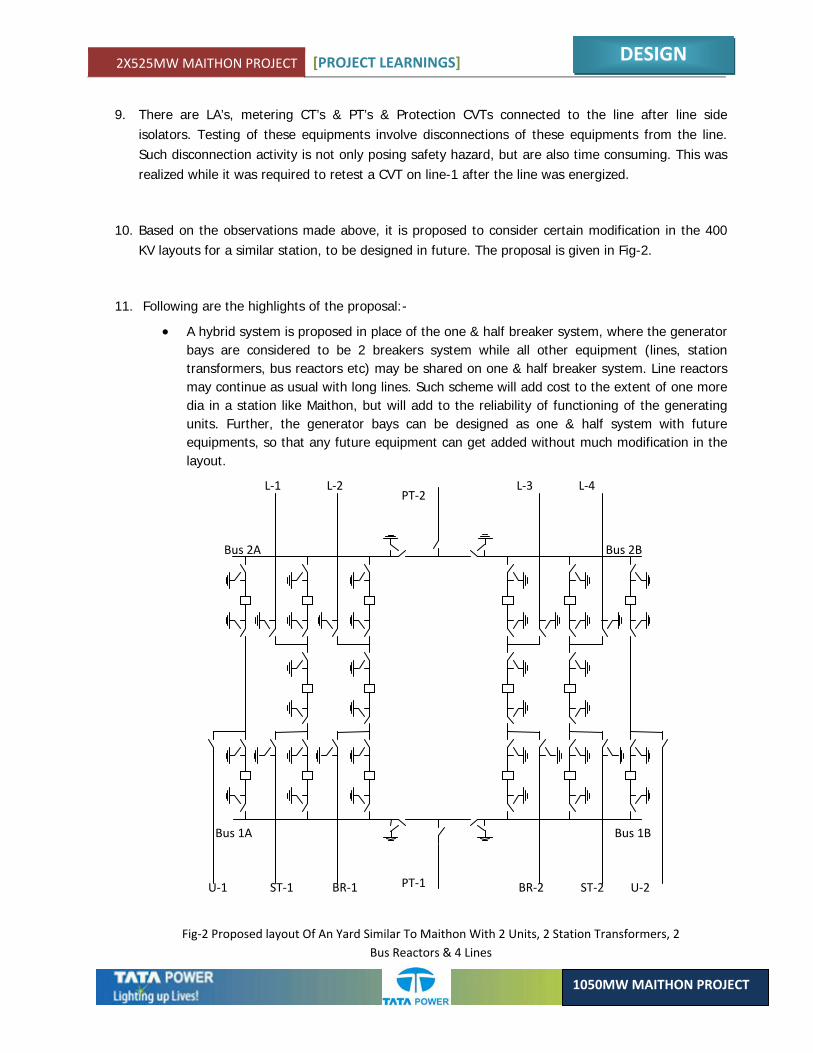
Fig‐2 Proposed layout Of An Yard Similar To Maithon With 2 Units, 2 Station Transformers, 2 Bus Reactors & 4 Lines
9. There are LA’s, metering CT’s & PT’s & Protection CVTs connected to the line after line side isolators. Testing of these equipments involve disconnections of these equipments from the line. Such disconnection activity is not only posing safety hazard, but are also time consuming. This was realized while it was required to retest a CVT on line-1 after the line was energized.
10. Based on the observations made above, it is proposed to consider certain modification in the 400 KV layouts for a similar station, to be designed in future. The proposal is given in Fig-2.
11. Following are the highlights of the proposal:-
• A hybrid system is proposed in place of the one & half breaker system, where the generator bays are considered to be 2 breakers system while all other equipment (lines, station transformers, bus reactors etc) may be shared on one & half breaker system. Line reactors may continue as usual with long lines. Such scheme will add cost to the extent of one more dia in a station like Maithon, but will add to the reliability of functioning of the generating units. Further, the generator bays can be designed as one & half system with future equipments, so that any future equipment can get added without much modification in the layout.
2X525MW MAITHON PROJECT [PROJECT LEARNINGS]
DESIGN
1050MW MAITHON PROJECT
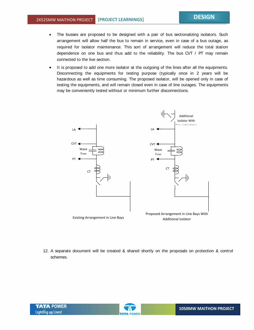
• The busses are proposed to be designed with a pair of bus sectionalizing isolators. Such arrangement will allow half the bus to remain in service, even in case of a bus outage, as required for isolator maintenance. This sort of arrangement will reduce the total station dependence on one bus and thus add to the reliability. The bus CVT / PT may remain connected to the live section.
• It is proposed to add one more isolator at the outgoing of the lines after all the equipments. Disconnecting the equipments for testing purpose (typically once in 2 years will be hazardous as well as time consuming. The proposed isolator, will be opened only in case of testing the equipments, and will remain closed even in case of line outages. The equipments may be conveniently tested without or minimum further disconnections.
PT
CVT
LA
CT
Wave Trap
LA
CVT
Wave Trap
PT
CT
Additional Isolator With
Ground Isolator
Existing Arrangement in Line Bays Proposed Arrangement in Line Bays With
Additional Isolator
12. A separate document will be created & shared shortly on the proposals on protection & control schemes.

2X525MW MAITHON PROJECT [PROJECT LEARNINGS]
DESIGN
1050MW MAITHON PROJECT
MECHANICAL
2.19. ALTERNATE METHOD OF PLATE HEAT EXCHANGER COOLING
Brief Description:
A plate heat exchanger is a type of heat exchanger that uses metal plates to transfer heat between two fluids.
Previous Scheme as per TCE:
The DMCW pump collects the hot water from auxiliaries and feeds the same into PHE and the cooled water coming out from PHE is used for cooling the same auxiliaries.
The above hot water entering the PHE is cooled with the help of ACW pump which feeds the cooled water from CW line to PHE and the hot water coming out from PHE is taken back to cooling tower via CW line.
2X525MW MAITHON PROJECT [PROJECT LEARNINGS]
DESIGN
1050MW MAITHON PROJECT
Modified Scheme:
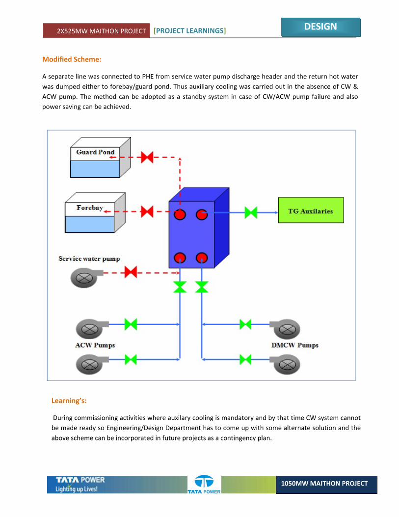
A separate line was connected to PHE from service water pump discharge header and the return hot water was dumped either to forebay/guard pond. Thus auxiliary cooling was carried out in the absence of CW & ACW pump. The method can be adopted as a standby system in case of CW/ACW pump failure and also power saving can be achieved.
Learning’s:
During commissioning activities where auxilary cooling is mandatory and by that time CW system cannot be made ready so Engineering/Design Department has to come up with some alternate solution and the above scheme can be incorporated in future projects as a contingency plan.


CHAPTER 3ERECTION

2X525MW MAITHON PROJECT [PROJECT LEARNINGS]
ERECTION
1050MW MAITHON PROJECT
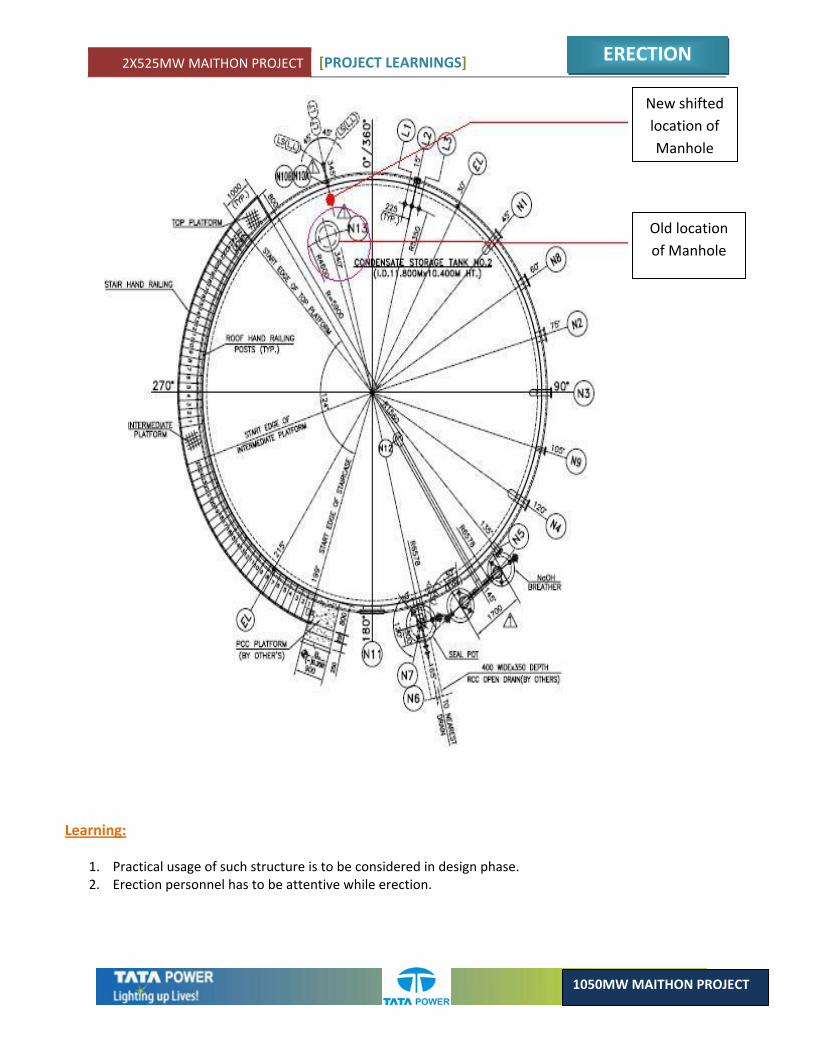
3.1. LOCATION OF MANHOLE CHANGED AT CST ROOF
MECHANICAL
Brief description of scheme: Condensate Storage Tank (CST) is meant to store the de mineralized water after its generation at DM Plant but before feeding into the water feed cycle. CST is a cylindrical shaped tank having dimensions 11.208 Mtr in height, and 11.800 Mtr is the outer diameter. Manhole is provided at the roof top in order to get inside the tank for maintenance purpose.
Modified scheme: To ease the access to the rung, manhole was shifted towards shell of the tank by 800 mm, in CST II.
Earlier Scheme: Ref Drg no.: P273‐M‐CST‐102 PE‐VO‐290‐167‐A002 As mentioned in the drawing, Manhole with cover (mark no. N13) was at a distance of 1300 mm from the shell of tank. In order to go inside the tank, rungs are provided along the shell. Thus entering from the manhole and landing on the rungs was a difficult task.
2X525MW MAITHON PROJECT [PROJECT LEARNINGS]
ERECTION
1050MW MAITHON PROJECT
New shifted location of Manhole
Old location of Manhole
Learning:
1. Practical usage of such structure is to be considered in design phase. 2. Erection personnel has to be attentive while erection.
2X525MW MAITHON PROJECT [PROJECT LEARNINGS]
ERECTION
1050MW MAITHON PROJECT
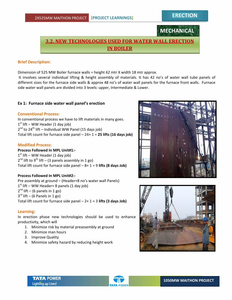
3.2. NEW TECHNOLOGIES USED FOR WATER WALL ERECTION IN BOILER
Brief Description: Dimension of 525 MW Boiler furnace walls = height 62 mtr X width 18 mtr approx. It involves several individual lifting & height assembly of materials. It has 42 no’s of water wall tube panels of different sizes for the furnace side walls & approx 48 no’s of water wall panels for the furnace front walls. Furnace side water wall panels are divided into 3 levels: upper, Intermediate & Lower.
Ex 1: Furnace side water wall panel’s erection Conventional Process: In conventional process we have to lift materials in many goes. 1st lift – WW Header (1 day job) 2nd to 24th lift – Individual WW Panel (15 days job) Total lift count for furnace side panel – 24+ 1 = 25 lifts (16 days job) Modified Process: Process Followed In MPL Unit#1:‐ 1st lift – WW Header (1 day job)
2nd lift to 9th lift – (3 panels assembly in 1 go) Total lift count for furnace side panel – 8+ 1 = 9 lifts (8 days Job) Process Followed In MPL Unit#2:‐ Pre assembly at ground – (Header+8 no’s water wall Panels) 1st lift – WW Header+ 8 panels (1 day job)
2nd lift – (6 panels in 1 go) 3rd lift – (6 Panels in 1 go) Total lift count for furnace side panel – 2+ 1 = 3 lifts (3 days Job) Learning: In erection phase new technologies should be used to enhance productivity, which will
1. Minimize risk by material preassembly at ground 2. Minimize man hours 3. Improve Quality 4. Minimize safety hazard by reducing height work
MECHANICAL

2X525MW MAITHON PROJECT [PROJECT LEARNINGS]
ERECTION
1050MW MAITHON PROJECT
Sr. No.
Unit
Lift Description
Total Wt.
Total No. of
lifts
Total No. of
days
Man days saved
1 Conventional
Pass I upper side WW panel
54.06
13
6
0
2 Unit#1
Pass I upper side WW panel
54.06
5
4
2
3 Unit#2
Pass I upper side WW panel
54.06
1
1
5
Other Examples:
Buck Stays pre fabricated and lifted Boiler 1st Pass Roof Panel erection
2X525MW MAITHON PROJECT [PROJECT LEARNINGS]
ERECTION
1050MW MAITHON PROJECT
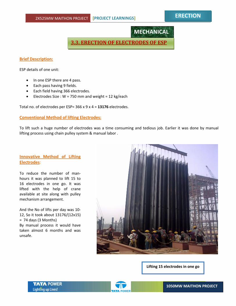
3.3. ERECTION OF ELECTRODES OF ESP
Innovative Method of Lifting Electrodes: To reduce the number of man‐hours it was planned to lift 15 to 16 electrodes in one go. It was lifted with the help of crane available at site along with pulley mechanism arrangement. And the No of lifts per day was 10‐12, So it took about 13176/(12x15) = 74 days (3 Months) By manual process it would have taken almost 6 months and was unsafe.
Lifting 15 electrodes in one go
Brief Description: ESP details of one unit:
• In one ESP there are 4 pass. • Each pass having 9 fields. • Each field having 366 electrodes. • Electrodes Size : W = 750 mm and weight = 12 kg/each
Total no. of electrodes per ESP= 366 x 9 x 4 = 13176 electrodes. Conventional Method of lifting Electrodes: To lift such a huge number of electrodes was a time consuming and tedious job. Earlier it was done by manual lifting process using chain pulley system & manual labor .
MECHANICAL
2X525MW MAITHON PROJECT [PROJECT LEARNINGS]
ERECTION
1050MW MAITHON PROJECT
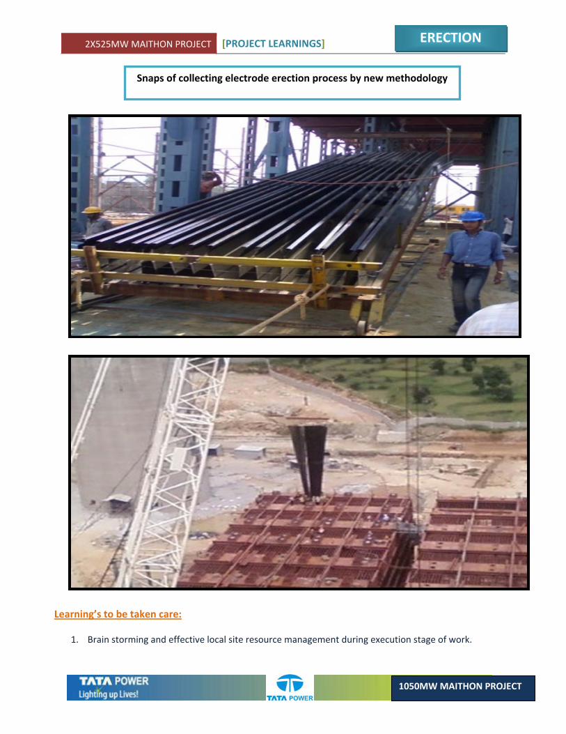
Snaps of collecting electrode erection process by new methodology
Learning’s to be taken care:
1. Brain storming and effective local site resource management during execution stage of work.
2X525MW MAITHON PROJECT [PROJECT LEARNINGS]
ERECTION
1050MW MAITHON PROJECT
3.4. PROCEDURAL CHANGE IN STRUCTURAL ERECTION FOR MILL & BUNKER BAY
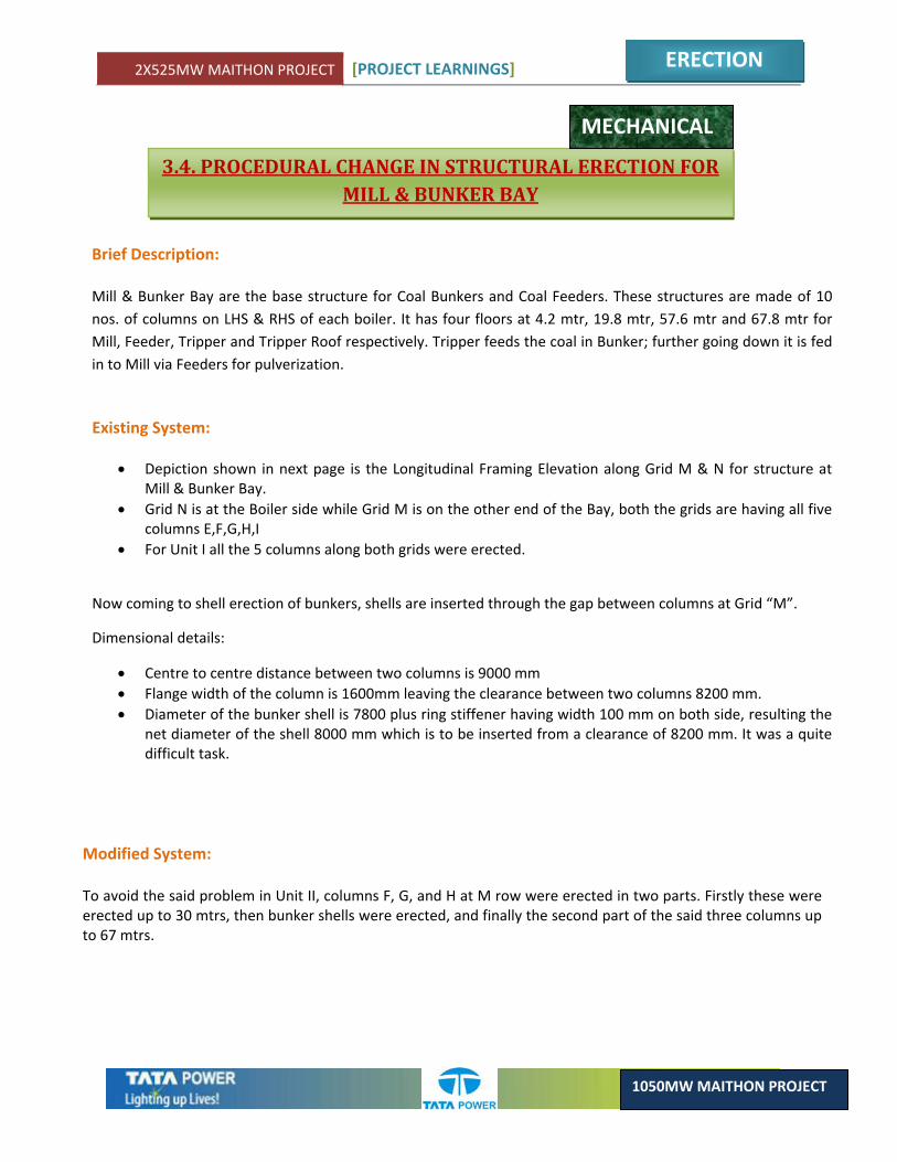
Brief Description: Mill & Bunker Bay are the base structure for Coal Bunkers and Coal Feeders. These structures are made of 10 nos. of columns on LHS & RHS of each boiler. It has four floors at 4.2 mtr, 19.8 mtr, 57.6 mtr and 67.8 mtr for Mill, Feeder, Tripper and Tripper Roof respectively. Tripper feeds the coal in Bunker; further going down it is fed in to Mill via Feeders for pulverization.
Existing System:
• Depiction shown in next page is the Longitudinal Framing Elevation along Grid M & N for structure at Mill & Bunker Bay.
• Grid N is at the Boiler side while Grid M is on the other end of the Bay, both the grids are having all five columns E,F,G,H,I
• For Unit I all the 5 columns along both grids were erected.
Now coming to shell erection of bunkers, shells are inserted through the gap between columns at Grid “M”.
Dimensional details:
• Centre to centre distance between two columns is 9000 mm • Flange width of the column is 1600mm leaving the clearance between two columns 8200 mm. • Diameter of the bunker shell is 7800 plus ring stiffener having width 100 mm on both side, resulting the
net diameter of the shell 8000 mm which is to be inserted from a clearance of 8200 mm. It was a quite difficult task.
Modified System: To avoid the said problem in Unit II, columns F, G, and H at M row were erected in two parts. Firstly these were erected up to 30 mtrs, then bunker shells were erected, and finally the second part of the said three columns up to 67 mtrs.
MECHANICAL
2X525MW MAITHON PROJECT [PROJECT LEARNINGS]
ERECTION
1050MW MAITHON PROJECT
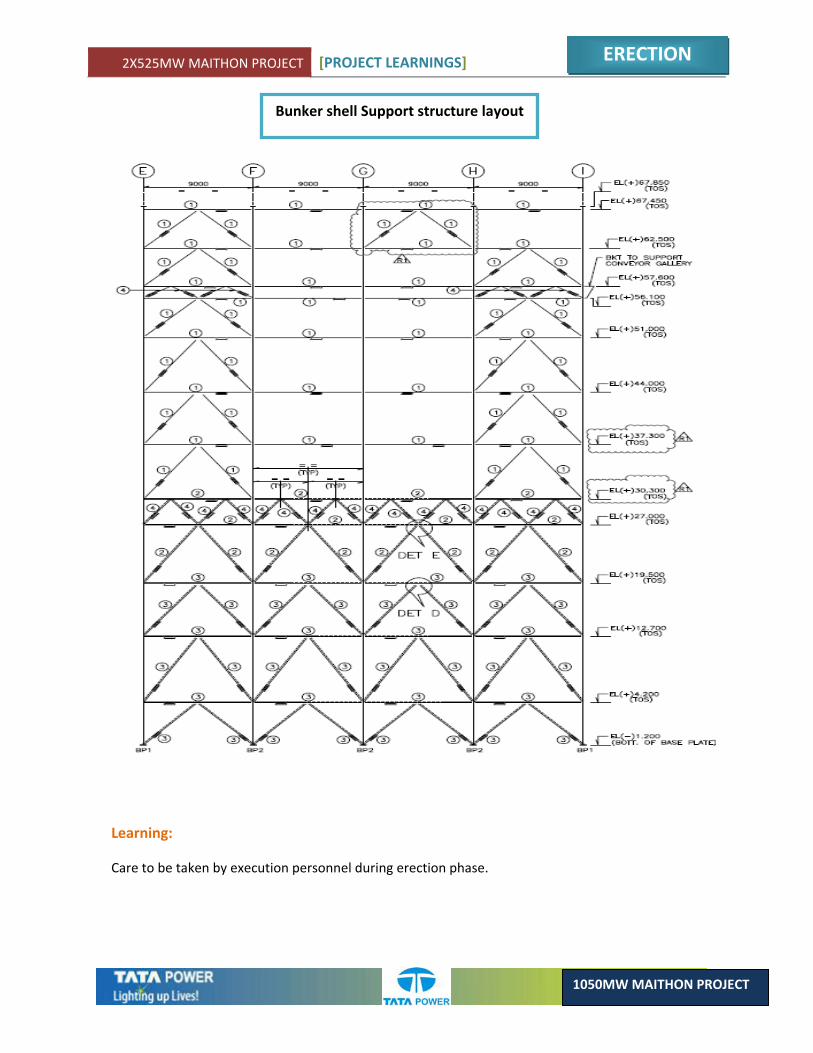
Bunker shell Support structure layout
Learning:
Care to be taken by execution personnel during erection phase.
2X525MW MAITHON PROJECT [PROJECT LEARNINGS]
ERECTION
1050MW MAITHON PROJECT
Brief Description: Saving resources and cutting costs, protecting the environment and using renewable energies are the criteria which are important for modern constructions, and as such, construction engineers today face the complex challenges of “integral planning”, demanding the interaction of various disciplines to create a construction with optimum efficiency whilst saving material and running costs.
Foundation work is not the glamorous side of project building. It is hard and tiresome work. But it’s also the work upon which all other work rests, and so a good foundation is critical to every project. And it is believed that nobody would want to repair a foundation; it must be right at the first time. With the expertise to take up the innovative challenges, lots of decisions were taken during implementation of the project. Some innovative cases are indicated herein considering importance of the structures.
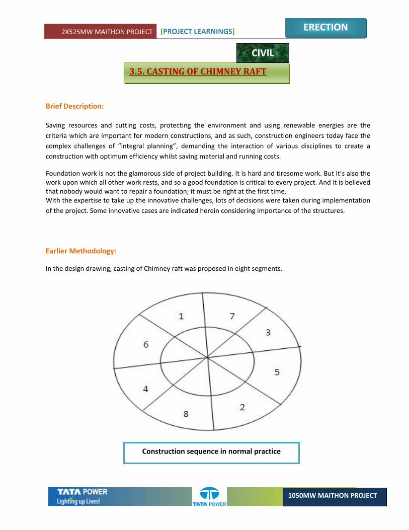
3.5. CASTING OF CHIMNEY RAFT
CIVIL
Earlier Methodology:
In the design drawing, casting of Chimney raft was proposed in eight segments.
Construction sequence in normal practice
2X525MW MAITHON PROJECT [PROJECT LEARNINGS]
ERECTION
1050MW MAITHON PROJECT
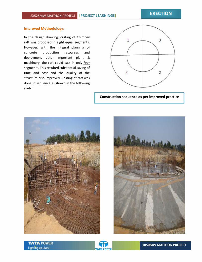
Improved Methodology:
In the design drawing, casting of Chimney raft was proposed in eight equal segments. However, with the integral planning of concrete production resources and deployment other important plant & machinery, the raft could cast in only four segments. This resulted substantial saving of time and cost and the quality of the structure also improved. Casting of raft was done in sequence as shown in the following sketch
Construction sequence as per improved practice
2X525MW MAITHON PROJECT [PROJECT LEARNINGS]
ERECTION
1050MW MAITHON PROJECT
3.6. LIGHTNING PROTECTION BY HIGH MASTS AT CONSTRUCTION SITE
ELECTRICAL
Description:
During initial construction period, the height of most of the structures at site are very low. Greater part of the site is almost a flat land. During monsoon & pre – monsoon periods such open areas become more prone to lightning strikes. This phenomenon has been practically observed at this site.
Original System:
As per the original system, no lightning protection was designed to cover the site during the initial period of Project commencement. This exposed a lot of small buildings & structures open to lightning strikes. Many a times this happened & also caused some damages to IT equipments.
Improved System:
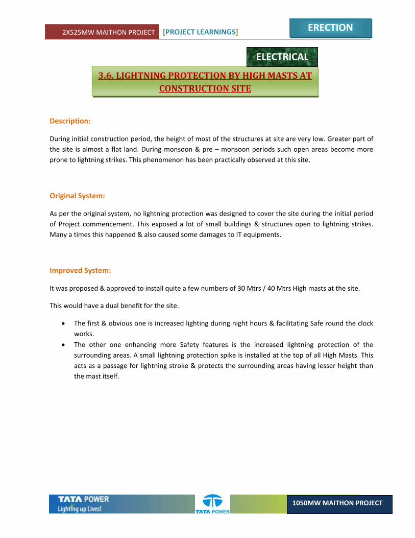
It was proposed & approved to install quite a few numbers of 30 Mtrs / 40 Mtrs High masts at the site.
This would have a dual benefit for the site.
• The first & obvious one is increased lighting during night hours & facilitating Safe round the clock works.
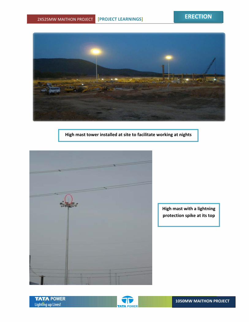
• The other one enhancing more Safety features is the increased lightning protection of the surrounding areas. A small lightning protection spike is installed at the top of all High Masts. This acts as a passage for lightning stroke & protects the surrounding areas having lesser height than the mast itself.
2X525MW MAITHON PROJECT [PROJECT LEARNINGS]
ERECTION
1050MW MAITHON PROJECT
High mast with a lightning protection spike at its top
High mast tower installed at site to facilitate working at nights
2X525MW MAITHON PROJECT [PROJECT LEARNINGS]
ERECTION
1050MW MAITHON PROJECT
3.7. COMPARTMENTALIZATION OF ASH POND
CIVIL
Brief Description:
Ash pond is constructed for stacking disposed Ash slurry from the plant before its final disposal. Design of ash pond is done after considering the quantum of ash from the plant during full load period for some specified period of 6 months to year or even more. Government used to finalize norms from time to time regarding percentage of Ash to be used by the company year after another accordingly we can’t stack Ash beyond some limit. Accordingly different practices like Ash slurry line or covered trucks are used for final disposal of Ash from Ash pond.
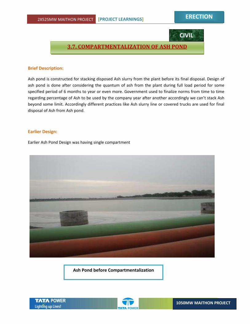
Earlier Design:
Earlier Ash Pond Design was having single compartment
Ash Pond before Compartmentalization

2X525MW MAITHON PROJECT [PROJECT LEARNINGS]
ERECTION
1050MW MAITHON PROJECT
Improved Design of Ash Pond:
Compartmentalization of ash pond was done into two parts so as to facilitate evacuation of Ash from one compartment while keeping the other compartment in operational mode. Peripheral drain was constructed around ash pond for disposal of storm water directly to Maithon dam so as to avoid involvement of expense in treatment of contaminated water.
Learning’s to be taken care:
1. Ash Pond must be designed in two parts to facilitate evacuation of ash from one pond while keeping the other compartment in operational mode.
2. Ash Pond must be designed in two parts to facilitate some maintenance work in one pond without hindering the Ash Disposal system
Compartmentalization of ash pond after improved design
2X525MW MAITHON PROJECT [PROJECT LEARNINGS]
ERECTION
1050MW MAITHON PROJECT
For an overview refer the picture in next page.
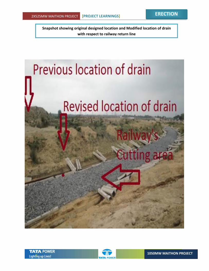
3.8. DRAIN LOCATION NEAR RAILWAY’S RETURN LINE
CIVIL
Brief Description:
Disposal of water from CHS system requires separate drainage arrangements for disposal of coal contaminated water after primary treatment with Geo‐tech fabric.
Earlier Design as per approved drawing:
As per approved drawing location of drain near railway return line was provided at a distance of nearly 40 Mtr which requires 5 to 6 Mtr deep excavation in hard rock below normal ground level along with plenty of space which may not be useful for any other purpose in future.
Modified as per site:
Location of drain was revised to new location adjoining railway cutting area hence reducing quantum of rock cutting to much lower extent. Also the balance space may easily be utilized for any purpose in the future. Also the execution of drain work at new location which require lesser time in completion due to reduction in the scope of work.
Learning’s to be taken care:
1. During design/ drawing phase location of drains etc. must always be considered after considering utilization of minimum space along with considering the structure nearer to other deep structures so as to reduce the quantum of work, use of additional space & incurrence of minimum cost.
2X525MW MAITHON PROJECT [PROJECT LEARNINGS]
ERECTION
1050MW MAITHON PROJECT
Snapshot showing original designed location and Modified location of drain with respect to railway return line
2X525MW MAITHON PROJECT [PROJECT LEARNINGS]
ERECTION
1050MW MAITHON PROJECT
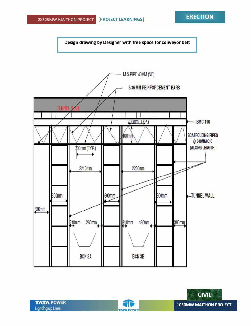
3.9. STAGING DESIGN OF CHP TUNNEL
CIVIL
Brief Description:
Tunnel of nearly 80 Mtr length with 9 to 10 degree slope was designed between Track Hopper & Pent house so as to cover the level difference between two structures. After filling the tunnel top area was utilized for movement of vehicles.
Earlier Methodology as ( Normal Practice ):
As per normal practice during execution stage after casting of tunnel slab access of man & machinery are restricted for 21 days which may hinder the progress of other departments like mechanical & operational team.
Improved Methodology:
Staging of tunnel portion was designed after considering sufficient space for the movement of man & machinery. This helps us in providing un‐interrupted front to mechanical as well as operational team. The area was restricted only for 2 days including the day of casting after considering safety requirements.
Learning’s to be taken care:
1. Staging of any structure can be designed after considering our system requirements so as to ensure availability of un‐interrupted front to other agencies.
2X525MW MAITHON PROJECT [PROJECT LEARNINGS]
ERECTION
1050MW MAITHON PROJECT
Design drawing by Designer with free space for conveyor belt
CIVIL

2X525MW MAITHON PROJECT [PROJECT LEARNINGS]
ERECTION
1050MW MAITHON PROJECT
3.10. ROAD CONSTRUCTION NEAR RAILWAY’S CUTTING AREA AFTER PROVIDING RETAINING WALL
Brief Description:
Road from two alternate routes are being constructed for access to the CHP area for safety as well as facilitating un interrupted movement of coal trucks.
Earlier Design:
As per site situations sufficient space was not available for providing road between Drive house of Stacker reclaimer & Railway’s cutting area.
Improved Design:
During execution stage Retaining wall was planned for providing road between drive house of Stacker reclaimer & Railway’s cutting area. Cost involved in the construction of Retaining wall is on much lower side against the cost saved during regular use of that route.
Learning’s to be taken care:
1. Two alternate routes must always be considered for the access to any important structure in view of safety as well as un‐ interrupted access of machinery to that structure.
2. In case sufficient space is not available for the construction of road or any other structure at two different elevations, retaining wall construction can be adopted for best utilization of available space after filling the slope portion available inside the retaining wall.
2X525MW MAITHON PROJECT [PROJECT LEARNINGS]
ERECTION
1050MW MAITHON PROJECT
CIVIL
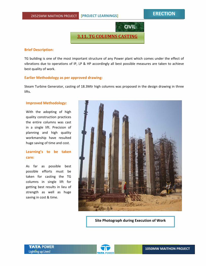
3.11. TG COLUMNS CASTING
Brief Description:
TG building is one of the most important structure of any Power plant which comes under the effect of vibrations due to operations of IP, LP & HP accordingly all best possible measures are taken to achieve best quality of work.
Earlier Methodology as per approved drawing:
Steam Turbine Generator, casting of 18.3Mtr high columns was proposed in the design drawing in three lifts.
Improved Methodology:
With the adopting of high quality construction practices the entire columns was cast in a single lift. Precision of planning and high quality workmanship have resulted huge saving of time and cost.
Learning’s to be taken care:
As far as possible best possible efforts must be taken for casting the TG columns in single lift for getting best results in lieu of strength as well as huge saving in cost & time.
Site Photograph during Execution of Work
2X525MW MAITHON PROJECT [PROJECT LEARNINGS]
ERECTION
1050MW MAITHON PROJECT
MECHANICAL
3.12. RELOCATION OF IBD SUMP PITS
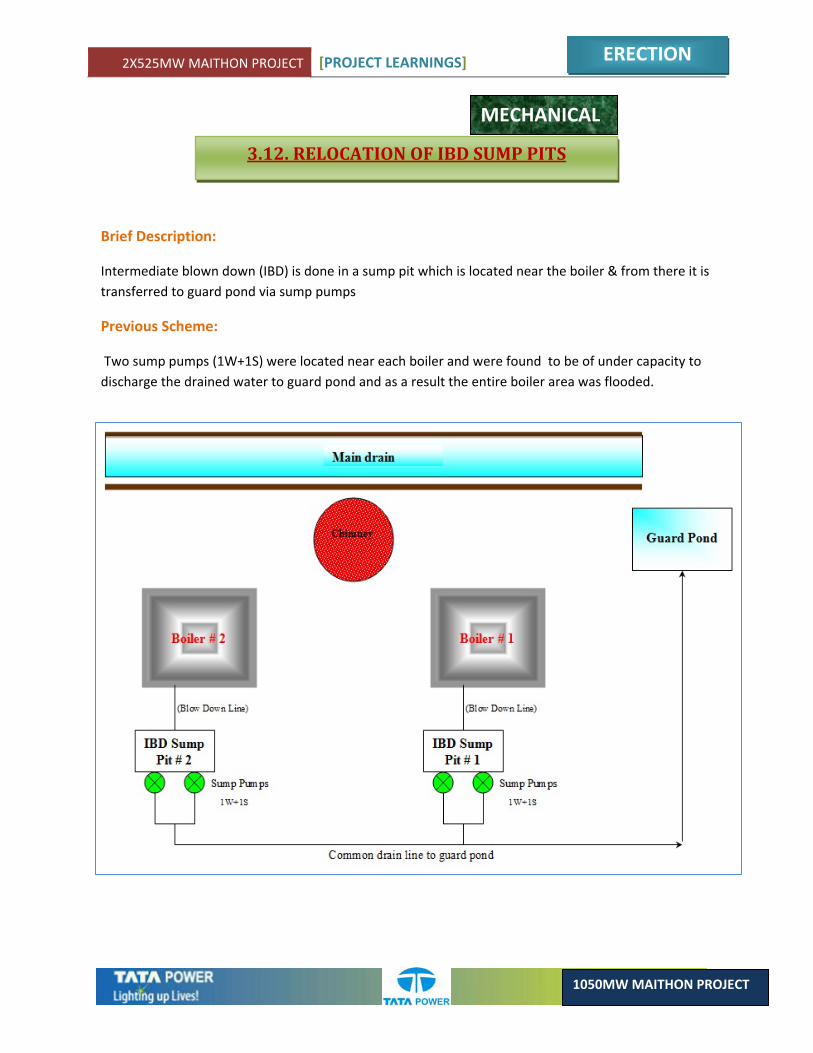
Brief Description:
Intermediate blown down (IBD) is done in a sump pit which is located near the boiler & from there it is transferred to guard pond via sump pumps
Previous Scheme:
Two sump pumps (1W+1S) were located near each boiler and were found to be of under capacity to discharge the drained water to guard pond and as a result the entire boiler area was flooded.
2X525MW MAITHON PROJECT [PROJECT LEARNINGS]
ERECTION
1050MW MAITHON PROJECT
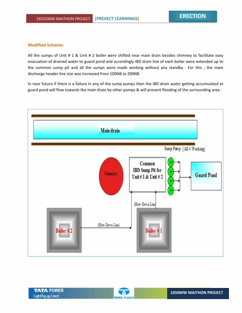
Modified Scheme:
All the sumps of Unit # 1 & Unit # 2 boiler were shifted near main drain besides chimney to facilitate easy evacuation of drained water to guard pond and accordingly IBD drain line of each boiler were extended up to the common sump pit and all the sumps were made working without any standby . For this , the main discharge header line size was increased from 100NB to 200NB.
In near future if there is a failure in any of the sump pumps then the IBD drain water getting accumulated at guard pond will flow towards the main drain by other pumps & will prevent flooding of the surrounding area .
2X525MW MAITHON PROJECT [PROJECT LEARNINGS]
ERECTION
1050MW MAITHON PROJECT
1 E 1 F 1G 1 H
2 D 2 C 2 B 2A
Electrical Control Bldg
COAL BUNKERS
COAL BUNKERS
Less space for the erection of bunker 1H & 2A
MECHANICAL
3.13. BUNKER SHELL ERECTION BY MONORAIL & WINCH INSTEAD OF CRANE
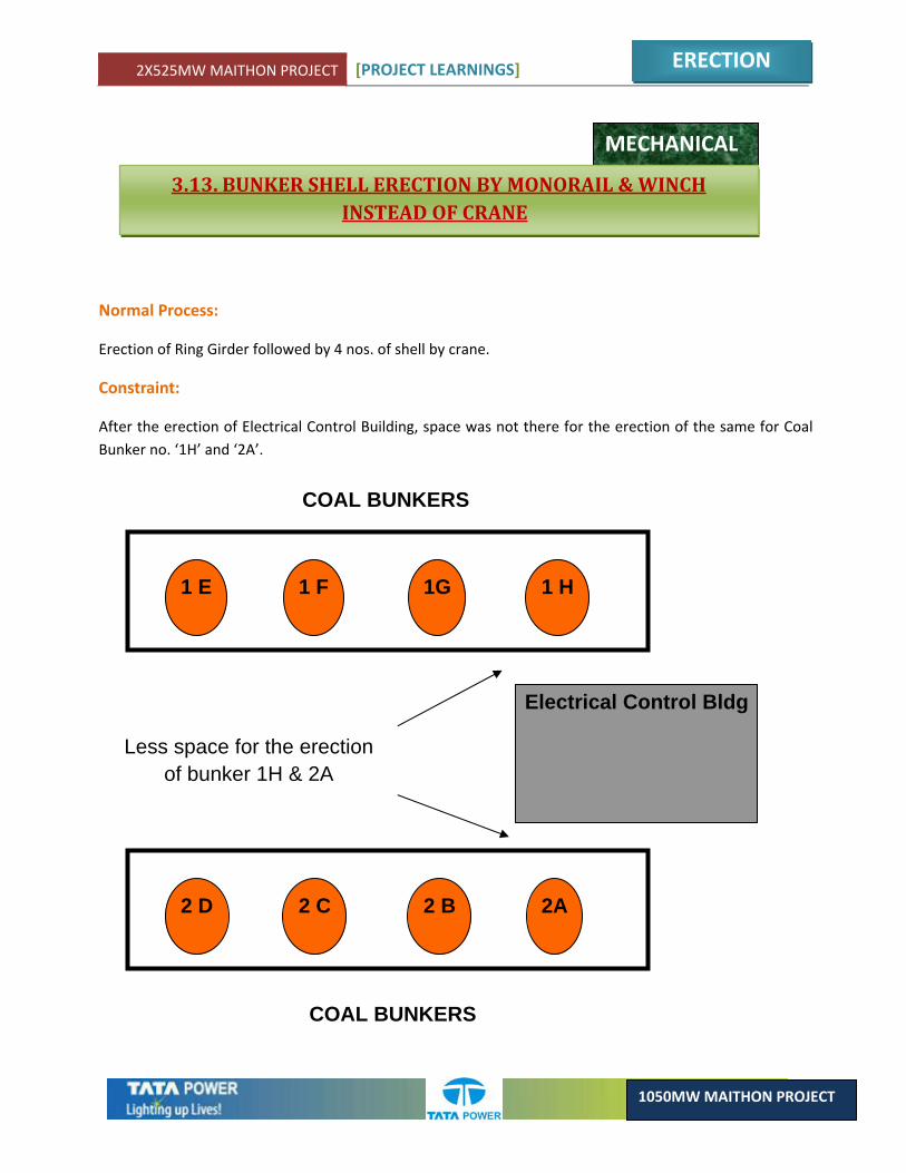
Normal Process:
Erection of Ring Girder followed by 4 nos. of shell by crane.
Constraint:
After the erection of Electrical Control Building, space was not there for the erection of the same for Coal Bunker no. ‘1H’ and ‘2A’.
2X525MW MAITHON PROJECT [PROJECT LEARNINGS]
ERECTION
1050MW MAITHON PROJECT
Electrical Control Bldg
?
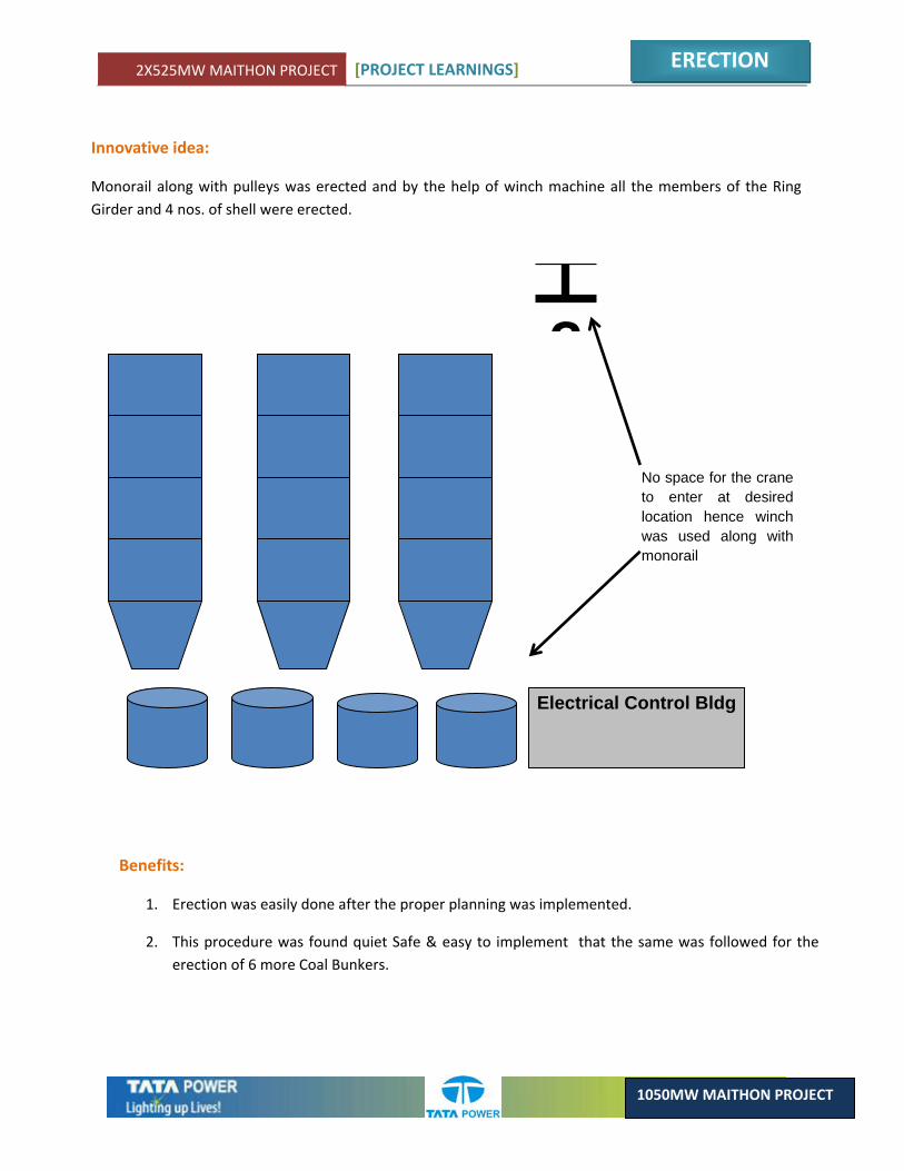
No space for the crane to enter at desired location hence winch was used along with monorail
Innovative idea:
Monorail along with pulleys was erected and by the help of winch machine all the members of the Ring Girder and 4 nos. of shell were erected.
Benefits:
1. Erection was easily done after the proper planning was implemented.
2. This procedure was found quiet Safe & easy to implement that the same was followed for the erection of 6 more Coal Bunkers.
2X525MW MAITHON PROJECT [PROJECT LEARNINGS]
ERECTION
1050MW MAITHON PROJECT
MECHANICAL
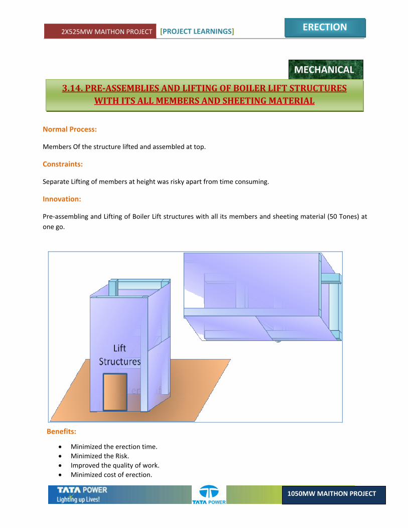
3.14. PREASSEMBLIES AND LIFTING OF BOILER LIFT STRUCTURES WITH ITS ALL MEMBERS AND SHEETING MATERIAL
Normal Process:
Members Of the structure lifted and assembled at top.
Constraints:
Separate Lifting of members at height was risky apart from time consuming.
Innovation:
Pre‐assembling and Lifting of Boiler Lift structures with all its members and sheeting material (50 Tones) at one go.
Benefits:
• Minimized the erection time. • Minimized the Risk. • Improved the quality of work. • Minimized cost of erection.

2X525MW MAITHON PROJECT [PROJECT LEARNINGS]
ERECTION
1050MW MAITHON PROJECT
MECHANICAL
3.15. MODIFICATION OF IBD EXHAUST PIPE (IN BOTH BOILERS)
Problem faced: ‐ Erection of IBD exhaust pipe done as per design drawing but at the time of light up it was found that the condensed water which was coming out from exhaust pipe were going directly to Boiler Elevator machine room & also filling the pathway to machine room. The lift is situated beside the IBD exhaust pipe. The condensed hot water were going to lift machine room which caused interruption in erection of machine room & in future also we would have faced lots of problem while operation & maintenance of Boiler Lift.
Modification done: ‐ To rectify the problem we have to increase height of Exhaust pipe by 4 meter length. As per the design the height of exhaust pipe was 81175 mm. We have lengthened the pipe by 4 meter to avoid the Hot water spraying & accumulation at the lift machine room. The revised height for IBD exhaust pipe is 85175 mm.
Challenges during modification –
• Cutting of existing pipe just below the bend portion. (EL 80 meter) • Material of extra length (Dia 660 X 8 mm thickness)
Extra support due to increase in height of 4 meter.
CHAPTER 4COMMISSIONING

2X525MW MAITHON PROJECT [PROJECT LEARNINGS]
COMMISSIONING
1050MW MAITHON PROJECT
4.1. POWER CIRCUIT MODIFICATION FOR IDCT VIBRATION TRANSMITTER
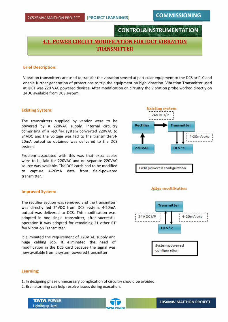
Brief Description: Vibration transmitters are used to transfer the vibration sensed at particular equipment to the DCS or PLC and enable further generation of protections to trip the equipment on high vibration. Vibration Transmitter used at IDCT was 220 VAC powered devices. After modification on circuitry the vibration probe worked directly on 24DC available from DCS system.
Existing System: The transmitters supplied by vendor were to be powered by a 220VAC supply. Internal circuitry comprising of a rectifier system converted 220VAC to 24VDC and the voltage was fed to the transmitter.4‐20mA output so obtained was delivered to the DCS system.
Problem associated with this was that extra cables were to be laid for 220VAC and no separate 220VAC source was available. The DCS cards had to be modified to capture 4‐20mA data from field‐powered transmitter.
Improved System: The rectifier section was removed and the transmitter was directly fed 24VDC from DCS system. 4‐20mA output was delivered to DCS. This modification was adopted in one single transmitter, after successful operation it was adopted for remaining 21 other CT fan Vibration Transmitter.
It eliminated the requirement of 220V AC supply and huge cabling job. It eliminated the need of modification in the DCS card because the signal was now available from a system‐powered transmitter.
Learning: 1. In designing phase unnecessary complication of circuitry should be avoided. 2. Brainstorming can help resolve issues during execution.
CONTROL&INSTRUMENTATION
2X525MW MAITHON PROJECT [PROJECT LEARNINGS]
COMMISSIONING
1050MW MAITHON PROJECT
4.2. AVOIDANCE OF TRIPPING OF MDBFP PUMP ON HIGH VIBRATION IN MANUAL MODE
CONTROL&INSTRUMENTATION
Brief Description: Motor driven Boiler Feed Pump is critical equipment in a thermal Power Plant. As an important component of the Feed water Cycle, it’s efficient and trouble‐free operation is very important. On manual operation, MDBFP used to trip on high vibration due to deviation in actual suction pressure and pump characteristics for that operating pressure.
Existing System:
In manual operation, MDBFP used to trip on high vibration. The cause was traced to the unavailability of Optimum Suction flow –Discharge pressure curve to the operator. During manual operation, any deviation from the curve would cause high vibration and thereby trip MDBFP. The curve was implemented in logic only for auto operation.
Improved System:
An optimum value derived from the Optimum Suction flow –Discharge pressure curve was made available to operation engineer so that there was minimum deviation from the curve, during manual operation and thereby prevent high vibration tripping .Same scheme has been incorporated in U#2 with good results.
Benefits after Modification:
Prevention of tripping due to high vibration. Cost, operational productivity Operation engineer can maintain the optimum discharge pressure as per the suction flow.
Learning:
1. Tripping due to unavailability of equipment characteristics to the operator for manual operation can be avoided by adequate support from automation department.
2. Brainstorming and Root Cause Analysis are efficient tools to find out and counteract on unwanted tripping and enable efficient operation.
2X525MW MAITHON PROJECT [PROJECT LEARNINGS]
COMMISSIONING
1050MW MAITHON PROJECT
2X525MW MAITHON PROJECT [PROJECT LEARNINGS]
COMMISSIONING
1050MW MAITHON PROJECT
Sludge Transfer Pump
Suction to pump
Manual Priming line for initial start up of pump
Pump discharge to ash sump tank
Sludge Pit
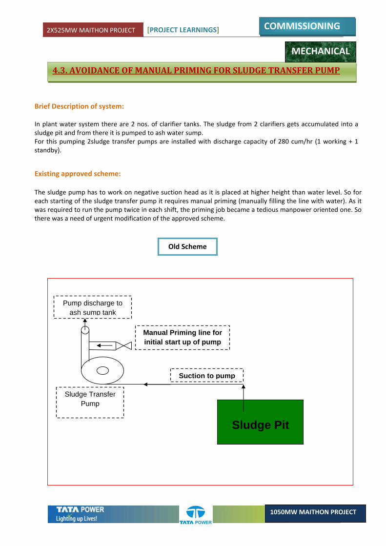
4.3. AVOIDANCE OF MANUAL PRIMING FOR SLUDGE TRANSFER PUMP
Brief Description of system: In plant water system there are 2 nos. of clarifier tanks. The sludge from 2 clarifiers gets accumulated into a sludge pit and from there it is pumped to ash water sump. For this pumping 2sludge transfer pumps are installed with discharge capacity of 280 cum/hr (1 working + 1 standby).
Existing approved scheme: The sludge pump has to work on negative suction head as it is placed at higher height than water level. So for each starting of the sludge transfer pump it requires manual priming (manually filling the line with water). As it was required to run the pump twice in each shift, the priming job became a tedious manpower oriented one. So there was a need of urgent modification of the approved scheme.
Old Scheme
MECHANICAL
2X525MW MAITHON PROJECT [PROJECT LEARNINGS]
COMMISSIONING
1050MW MAITHON PROJECT
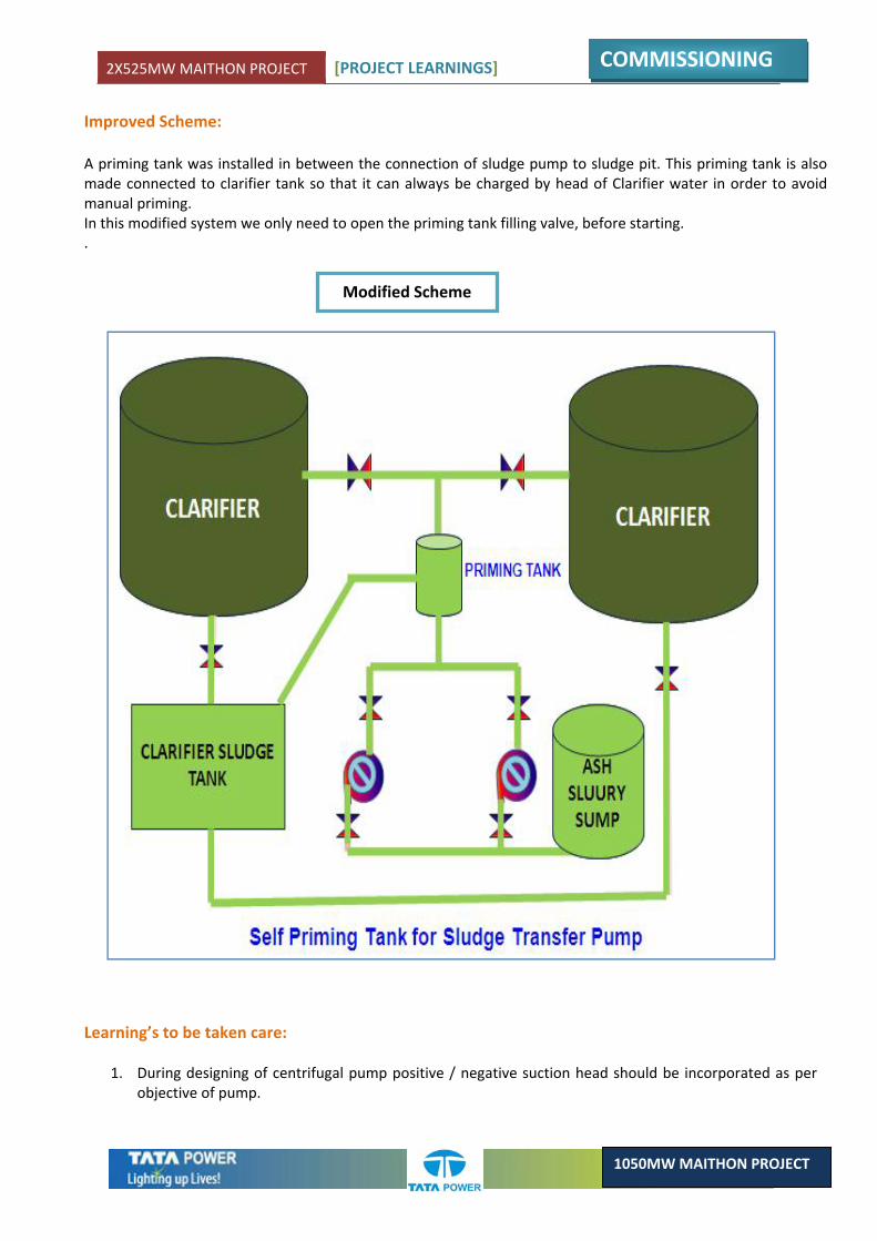
Improved Scheme: A priming tank was installed in between the connection of sludge pump to sludge pit. This priming tank is also made connected to clarifier tank so that it can always be charged by head of Clarifier water in order to avoid manual priming. In this modified system we only need to open the priming tank filling valve, before starting. .
Modified Scheme
Learning’s to be taken care:
1. During designing of centrifugal pump positive / negative suction head should be incorporated as per objective of pump.

2X525MW MAITHON PROJECT [PROJECT LEARNINGS]
COMMISSIONING
1050MW MAITHON PROJECT
4.4. FEEDER MODIFICATION FOR RELIABLE OPERATION OF CW PUMPS
Brief Description: For circulation of cooling water each unit is having 3 no. of (2MW) CW pumps. All these pump motors are fed from 6.6kV CWPH switch board. CWPH board has 2 bus system arrangements, (Bus#1 & 2) which are fed from 6.6kV station board of Unit#1 & 2 respectively. (I.e. OCB & OCC)
Existing Scheme: As per designed approved scheme all the three CW Motor feeder were on single Bus –A & B of 6.6 KV CWPH Switchgear for respective unit 1 &2 (CW‐1A, 1B, 1C for unit#1) (CW‐2A, 2B, 2C. For unit#2) In case of any bus problem, unit will shut down due to unavailability of cooling pump/system.
ELECTRICAL
2X525MW MAITHON PROJECT [PROJECT LEARNINGS]
COMMISSIONING
1050MW MAITHON PROJECT
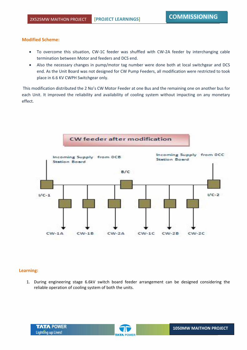
Modified Scheme:
• To overcome this situation, CW‐1C feeder was shuffled with CW‐2A feeder by interchanging cable termination between Motor and feeders and DCS end.
• Also the necessary changes in pump/motor tag number were done both at local switchgear and DCS end. As the Unit Board was not designed for CW Pump Feeders, all modification were restricted to took place in 6.6 KV CWPH Switchgear only.
This modification distributed the 2 No’s CW Motor Feeder at one Bus and the remaining one on another bus for each Unit. It improved the reliability and availability of cooling system without impacting on any monetary effect.
Learning:
1. During engineering stage 6.6kV switch board feeder arrangement can be designed considering the reliable operation of cooling system of both the units.
2X525MW MAITHON PROJECT [PROJECT LEARNINGS]
COMMISSIONING
1050MW MAITHON PROJECT
4.5. DOUBLE RUN CABLE ENTRY PROBLEM IN SWITCHGEAR
ELECTRICAL
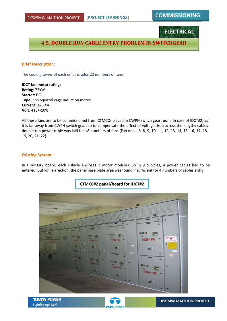
Brief Description: The cooling tower of each unit includes 22 numbers of fans: IDCT fan motor rating: Rating: 75kW Starter: DOL Type: 3ph Squirrel cage induction motor Current: 126.4A Volt: 415+‐10% All these fans are to be commissioned from CTMCCs placed in CWPH switch gear room. In case of IDCT#2, as it is far away from CWPH switch gear, so to compensate the effect of voltage drop across the lengthy cables double run power cable was laid for 18 numbers of fans (Fan nos. : 6, 8, 9, 10, 11, 12, 13, 14, 15, 16, 17, 18, 19, 20, 21, 22)
Existing System: In CTMCC#2 board, each cubicle encloses 2 motor modules. So in 9 cubicles, 4 power cables had to be entered. But while erection, the panel base plate area was found insufficient for 4 numbers of cables entry.
CTMCC#2 panel/board for IDCT#2
2X525MW MAITHON PROJECT [PROJECT LEARNINGS]
COMMISSIONING
1050MW MAITHON PROJECT
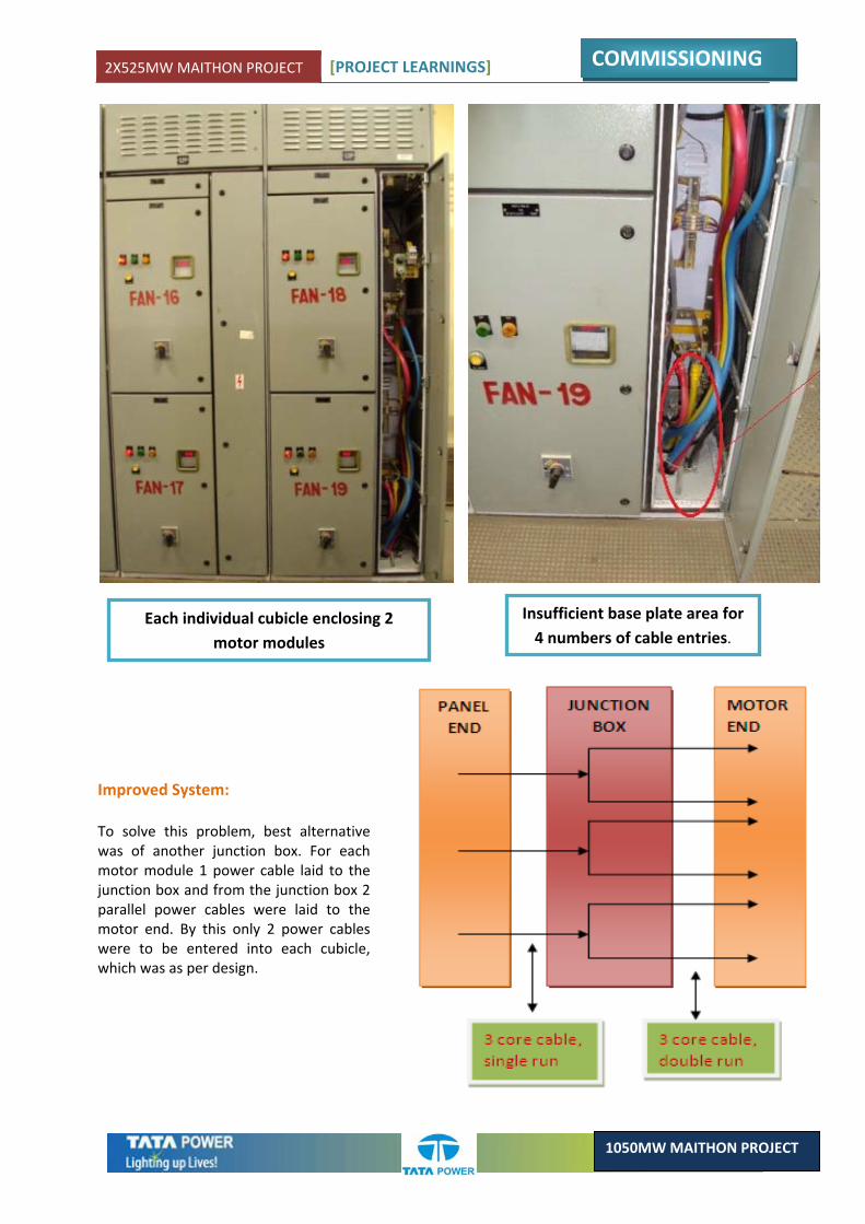
Each individual cubicle enclosing 2 motor modules
Insufficient base plate area for 4 numbers of cable entries.
Improved System: To solve this problem, best alternative was of another junction box. For each motor module 1 power cable laid to the junction box and from the junction box 2 parallel power cables were laid to the motor end. By this only 2 power cables were to be entered into each cubicle, which was as per design.

2X525MW MAITHON PROJECT [PROJECT LEARNINGS]
COMMISSIONING
1050MW MAITHON PROJECT
Junction Box connection meeting site requirements, quality standards and safety
Learning:
1. During designing required area of panel including base plate area need to be calculated considering total number of cables.
2. Sufficient space and height need to be provided to handle cable entry/termination job and for future maintenance jobs.
2X525MW MAITHON PROJECT [PROJECT LEARNINGS]
COMMISSIONING
1050MW MAITHON PROJECT
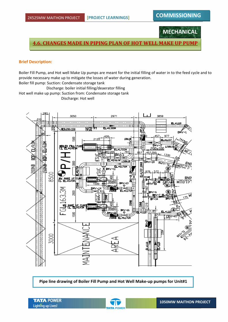
4.6. CHANGES MADE IN PIPING PLAN OF HOT WELL MAKE UP PUMP
MECHANICAL
Brief Description: Boiler Fill Pump, and Hot well Make Up pumps are meant for the initial filling of water in to the feed cycle and to provide necessary make up to mitigate the losses of water during generation. Boiler fill pump: Suction: Condensate storage tank
Discharge: boiler initial filling/deaerator filling Hot well make up pump: Suction from: Condensate storage tank
Discharge: Hot well
Pipe line drawing of Boiler Fill Pump and Hot Well Make‐up pumps for Unit#1
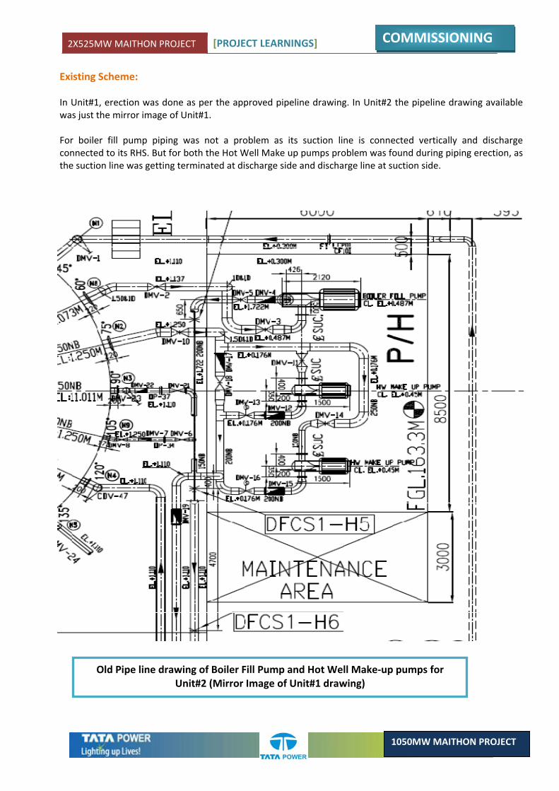
2X525MW MAITHON PROJECT [PROJECT LEARNINGS]
COMMISSIONING
1050MW MAITHON PROJECT
Existing Scheme: In Unit#1, erection was done as per the approved pipeline drawing. In Unit#2 the pipeline drawing available was just the mirror image of Unit#1. For boiler fill pump piping was not a problem as its suction line is connected vertically and discharge connected to its RHS. But for both the Hot Well Make up pumps problem was found during piping erection, as the suction line was getting terminated at discharge side and discharge line at suction side.
Old Pipe line drawing of Boiler Fill Pump and Hot Well Make‐up pumps for Unit#2 (Mirror Image of Unit#1 drawing)
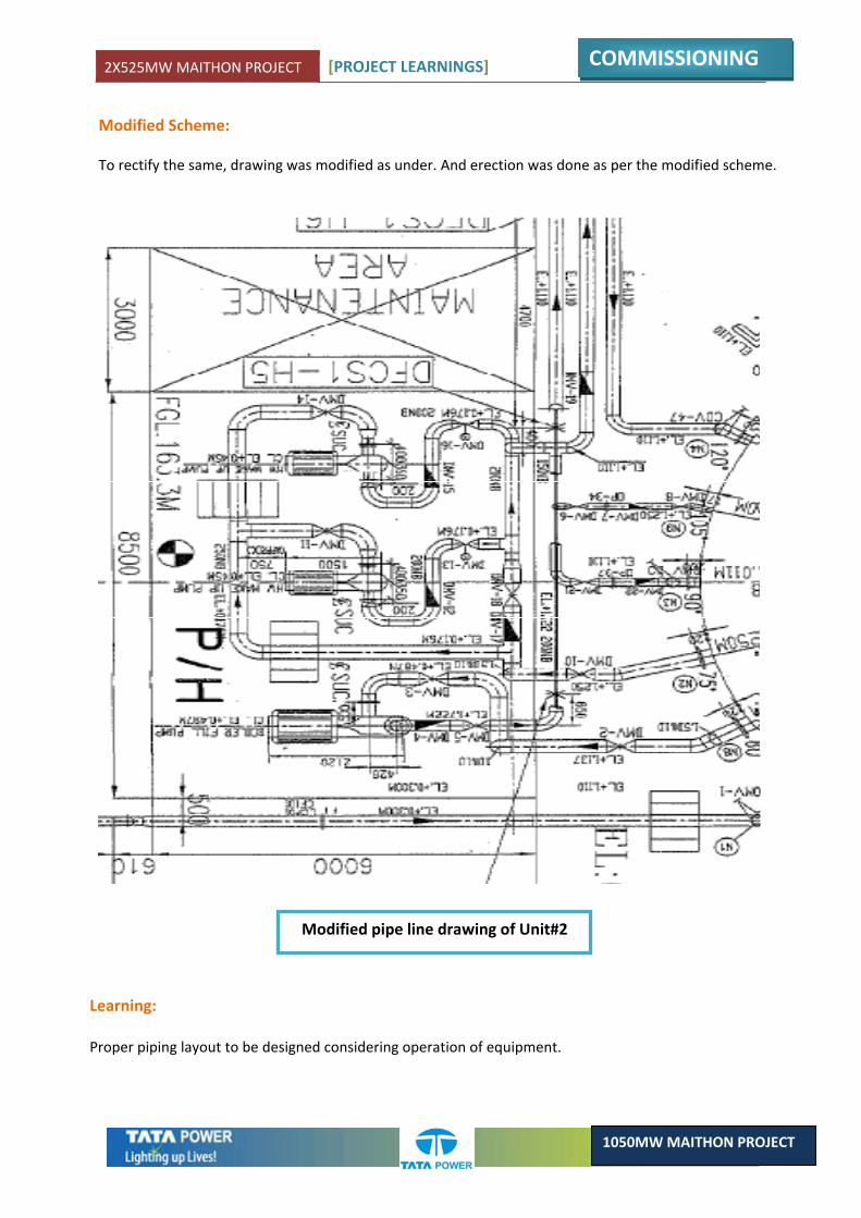
2X525MW MAITHON PROJECT [PROJECT LEARNINGS]
COMMISSIONING
1050MW MAITHON PROJECT
Modified Scheme: To rectify the same, drawing was modified as under. And erection was done as per the modified scheme.
Learning: Proper piping layout to be designed considering operation of equipment.
Modified pipe line drawing of Unit#2
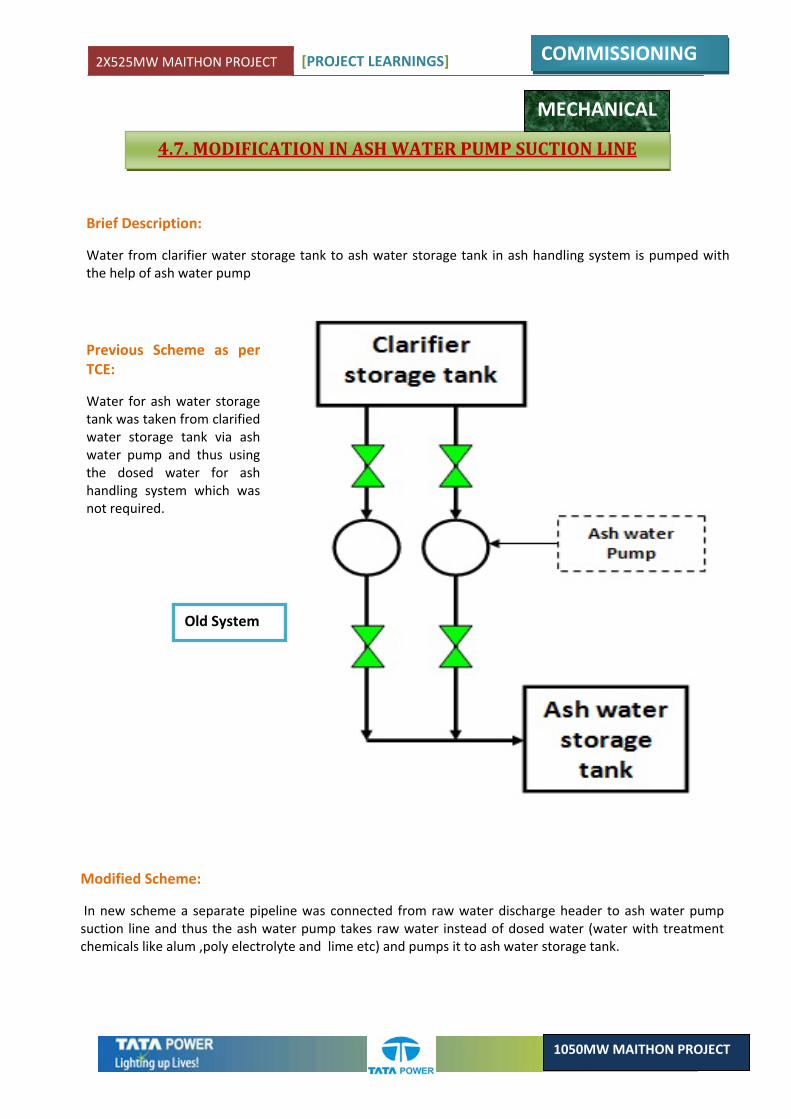
2X525MW MAITHON PROJECT [PROJECT LEARNINGS]
COMMISSIONING
1050MW MAITHON PROJECT
4.7. MODIFICATION IN ASH WATER PUMP SUCTION LINE
MECHANICAL
Brief Description:
Water from clarifier water storage tank to ash water storage tank in ash handling system is pumped with the help of ash water pump
Previous Scheme as per TCE:
Water for ash water storage tank was taken from clarified water storage tank via ash water pump and thus using the dosed water for ash handling system which was not required.
Old System
Modified Scheme:
In new scheme a separate pipeline was connected from raw water discharge header to ash water pump suction line and thus the ash water pump takes raw water instead of dosed water (water with treatment chemicals like alum ,poly electrolyte and lime etc) and pumps it to ash water storage tank.
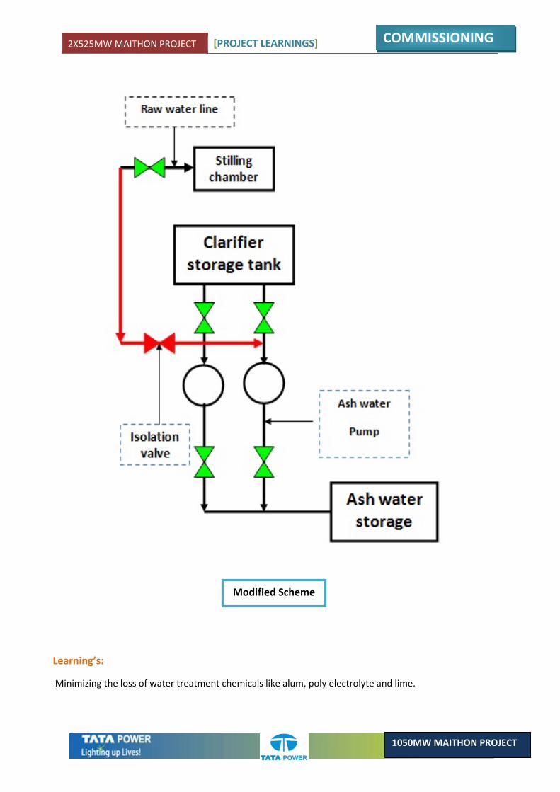
2X525MW MAITHON PROJECT [PROJECT LEARNINGS]
COMMISSIONING
1050MW MAITHON PROJECT
Learning’s:
Minimizing the loss of water treatment chemicals like alum, poly electrolyte and lime.
Modified Scheme

2X525MW MAITHON PROJECT [PROJECT LEARNINGS]
COMMISSIONING
1050MW MAITHON PROJECT
4.8. MODIFICATION IN ECP PANEL FOR CLOSING CIRCUIT OF GENERATOR CIRCUIT BREAKER
ELECTRICAL
Description:
• Generator CB from ECP panel can be closed in synchronization mode.
• Generator circuit breaker is having facility of auto synchronization through ATRS scheme and manual synchronization through synchroscope with synchronizing check relay (25).
• Modes of selection with the help of lockable synch switch relay one at the time.
• By ATRS auto turbine run up system synchronization, it interacts with the generator excitation system and turbine control system to adjust the voltage and the frequency and gives synchronizing permissive.
Original scheme:
As per design during closing of 400kV Generator CB & TIE CB’s from ECP panel, DC of both the Breaker is getting Paralleled in hardwire circuit and path for ATRS is not proper.
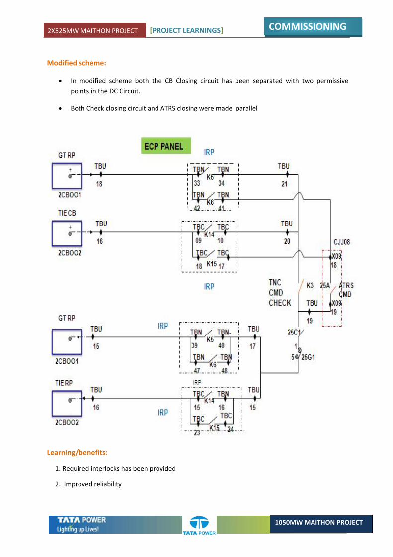
2X525MW MAITHON PROJECT [PROJECT LEARNINGS]
COMMISSIONING
1050MW MAITHON PROJECT
Modified scheme:
• In modified scheme both the CB Closing circuit has been separated with two permissive points in the DC Circuit.
• Both Check closing circuit and ATRS closing were made parallel
Learning/benefits:
1. Required interlocks has been provided
2. Improved reliability
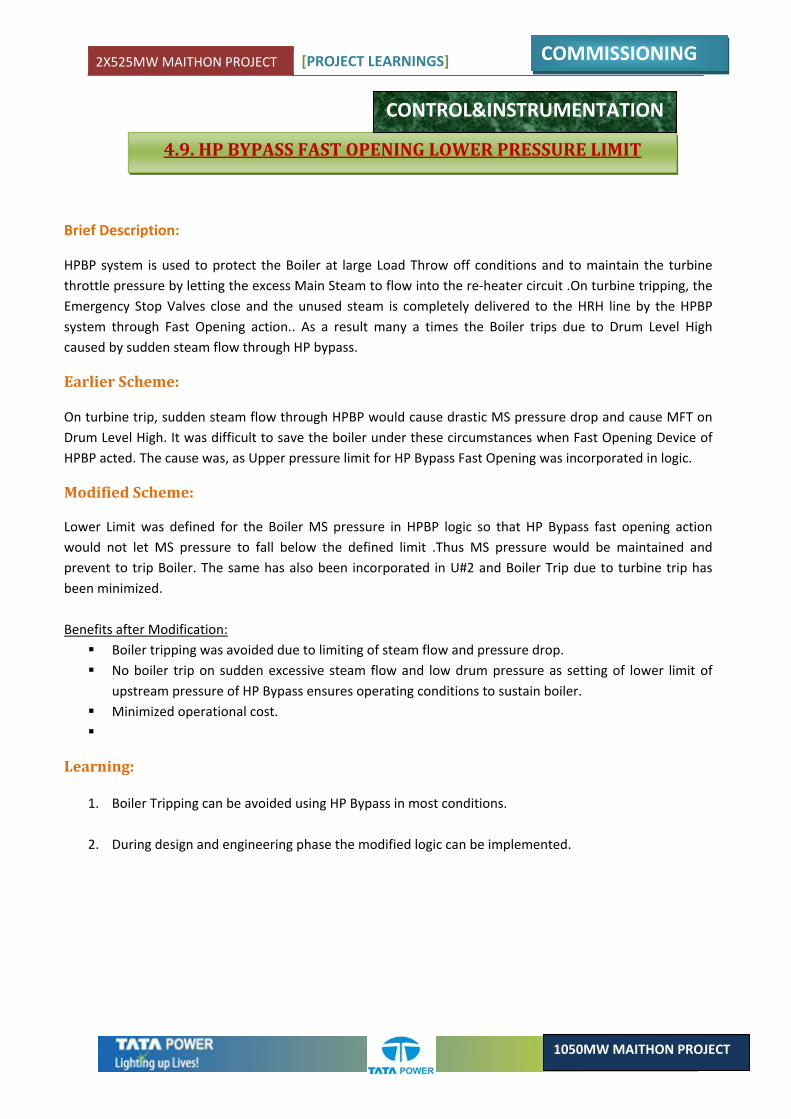
2X525MW MAITHON PROJECT [PROJECT LEARNINGS]
COMMISSIONING
1050MW MAITHON PROJECT
4.9. HP BYPASS FAST OPENING LOWER PRESSURE LIMIT
CONTROL&INSTRUMENTATION
Brief Description:
HPBP system is used to protect the Boiler at large Load Throw off conditions and to maintain the turbine throttle pressure by letting the excess Main Steam to flow into the re‐heater circuit .On turbine tripping, the Emergency Stop Valves close and the unused steam is completely delivered to the HRH line by the HPBP system through Fast Opening action.. As a result many a times the Boiler trips due to Drum Level High caused by sudden steam flow through HP bypass.
Earlier Scheme:
On turbine trip, sudden steam flow through HPBP would cause drastic MS pressure drop and cause MFT on Drum Level High. It was difficult to save the boiler under these circumstances when Fast Opening Device of HPBP acted. The cause was, as Upper pressure limit for HP Bypass Fast Opening was incorporated in logic.
Modified Scheme:
Lower Limit was defined for the Boiler MS pressure in HPBP logic so that HP Bypass fast opening action would not let MS pressure to fall below the defined limit .Thus MS pressure would be maintained and prevent to trip Boiler. The same has also been incorporated in U#2 and Boiler Trip due to turbine trip has been minimized. Benefits after Modification:
Boiler tripping was avoided due to limiting of steam flow and pressure drop. No boiler trip on sudden excessive steam flow and low drum pressure as setting of lower limit of
upstream pressure of HP Bypass ensures operating conditions to sustain boiler. Minimized operational cost.
Learning:
1. Boiler Tripping can be avoided using HP Bypass in most conditions.
2. During design and engineering phase the modified logic can be implemented.
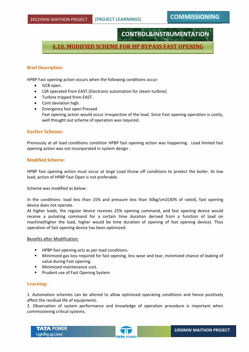
2X525MW MAITHON PROJECT [PROJECT LEARNINGS]
COMMISSIONING
1050MW MAITHON PROJECT
4.10. MODIFIED SCHEME FOR HP BYPASS FAST OPENING
Brief Description: HPBP Fast opening action occurs when the following conditions occur:
• GCB open. • LSR operated from EAST.(Electronic automation for steam turbine) • Turbine tripped from EAST. • Cont deviation high. • Emergency fast open Pressed
Fast opening action would occur irrespective of the load. Since Fast opening operation is costly, well thought out scheme of operation was required.
Earlier Scheme:
Previously at all load conditions condition HPBP fast opening action was happening . Load limited fast opening action was not incorporated in system design . Modified Scheme:
HPBP fast opening action must occur at large Load throw off conditions to protect the boiler. At low load, action of HPBP Fast Open is not preferable. Scheme was modified as below: In the conditions: load less than 15% and pressure less than 50kg/cm2(30% of rated), fast opening device does not operate. At higher loads, the regular device receives 25% opening command, and fast opening device would receive a pulsating command for a certain time duration derived from a function of load on machine(higher the load, higher would be time duration of opening of fast opening device). Thus operation of fast opening device has been optimized.
Benefits after Modification:
HPBP fast opening acts as per load conditions. Minimized gas loss required for fast opening, less wear and tear, minimized chance of leaking of
value during Fast opening. Minimized maintenance cost. Prudent use of Fast Opening System
Learning: 1. Automation schemes can be altered to allow optimized operating conditions and hence positively affect the residual life of equipments. 2. Observation of system performance and knowledge of operation procedure is important when commissioning critical systems.
CONTROL&INSTRUMENTATION
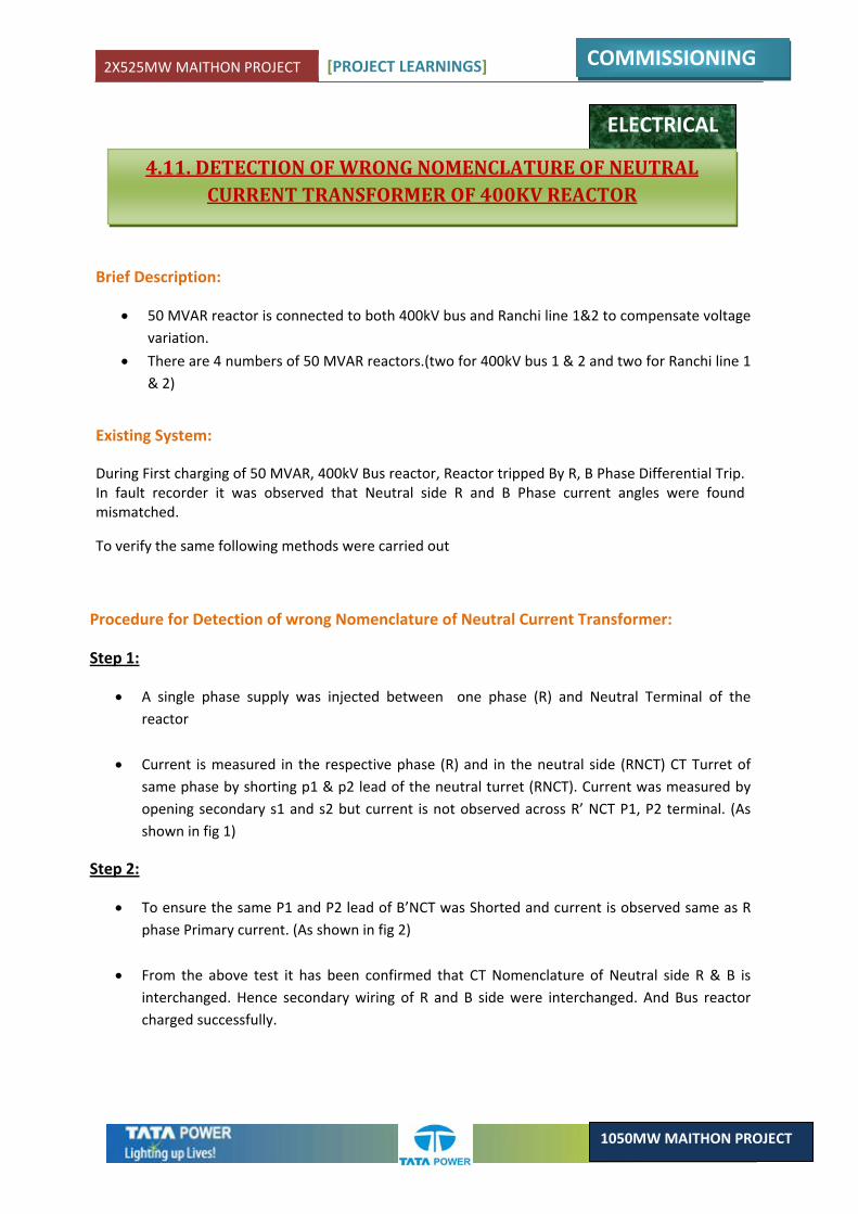
2X525MW MAITHON PROJECT [PROJECT LEARNINGS]
COMMISSIONING
1050MW MAITHON PROJECT
ELECTRICAL
4.11. DETECTION OF WRONG NOMENCLATURE OF NEUTRAL CURRENT TRANSFORMER OF 400KV REACTOR
Brief Description:
• 50 MVAR reactor is connected to both 400kV bus and Ranchi line 1&2 to compensate voltage variation.
• There are 4 numbers of 50 MVAR reactors.(two for 400kV bus 1 & 2 and two for Ranchi line 1 & 2)
Existing System:
During First charging of 50 MVAR, 400kV Bus reactor, Reactor tripped By R, B Phase Differential Trip. In fault recorder it was observed that Neutral side R and B Phase current angles were found mismatched.
To verify the same following methods were carried out
Procedure for Detection of wrong Nomenclature of Neutral Current Transformer:
Step 1:
• A single phase supply was injected between one phase (R) and Neutral Terminal of the reactor
• Current is measured in the respective phase (R) and in the neutral side (RNCT) CT Turret of same phase by shorting p1 & p2 lead of the neutral turret (RNCT). Current was measured by opening secondary s1 and s2 but current is not observed across R’ NCT P1, P2 terminal. (As shown in fig 1)
Step 2:
• To ensure the same P1 and P2 lead of B’NCT was Shorted and current is observed same as R phase Primary current. (As shown in fig 2)
• From the above test it has been confirmed that CT Nomenclature of Neutral side R & B is interchanged. Hence secondary wiring of R and B side were interchanged. And Bus reactor charged successfully.
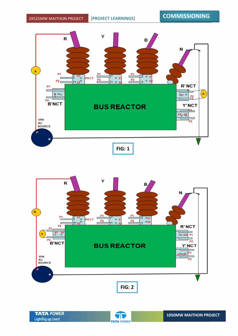
2X525MW MAITHON PROJECT [PROJECT LEARNINGS]
COMMISSIONING
1050MW MAITHON PROJECT
FIG: 1
FIG: 2
2X525MW MAITHON PROJECT [PROJECT LEARNINGS]
COMMISSIONING
1050MW MAITHON PROJECT
4.12. ELEVATOR MACHINE ROOM POWER & AC CONNECTION
ELECTRICAL
Description:
The main elevator of Technical Building is controlled from the Main machine room which is at Roof top of the building. The power connection for the elevator controller & motors is from the LT – 440 Volts panel at 0.0 Mtr. Level of Technical building.
Original scheme:
As per the original layout the pathway for cable carrying current to machine has not been shown in any of the drawings .Also the machine room being at roof level, the room gets heated up during long summers of this region. As a result this leads to frequent malfunctioning of the controller & tripping of the motor due to overheating. But no provisioning has been made for Air conditioning of this room.
Improved Scheme:
The cable for power supply to machine room was laid through cable tray designed & approved as per site requirement. Also as the elevator was facing frequent breakdown due to overheating problem; it was decided to put an Air Conditioning in the room to maintain the room temperature. This has led to a great reduction in the frequency of elevator breakdowns.
Learning:
1. Power supply cable to be incorporated during design stage. 2. Air condition equipment to be installed at machine room.
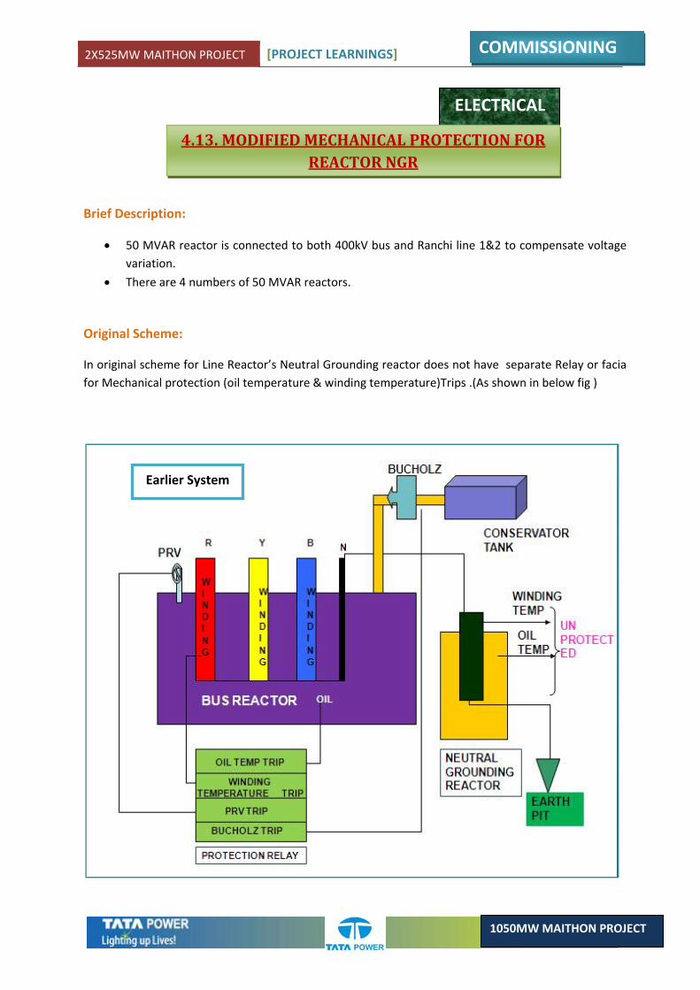
2X525MW MAITHON PROJECT [PROJECT LEARNINGS]
COMMISSIONING
1050MW MAITHON PROJECT
ELECTRICAL
4.13. MODIFIED MECHANICAL PROTECTION FOR REACTOR NGR
Brief Description:
• 50 MVAR reactor is connected to both 400kV bus and Ranchi line 1&2 to compensate voltage variation.
• There are 4 numbers of 50 MVAR reactors.
Original Scheme:
In original scheme for Line Reactor’s Neutral Grounding reactor does not have separate Relay or facia for Mechanical protection (oil temperature & winding temperature)Trips .(As shown in below fig )
Earlier System
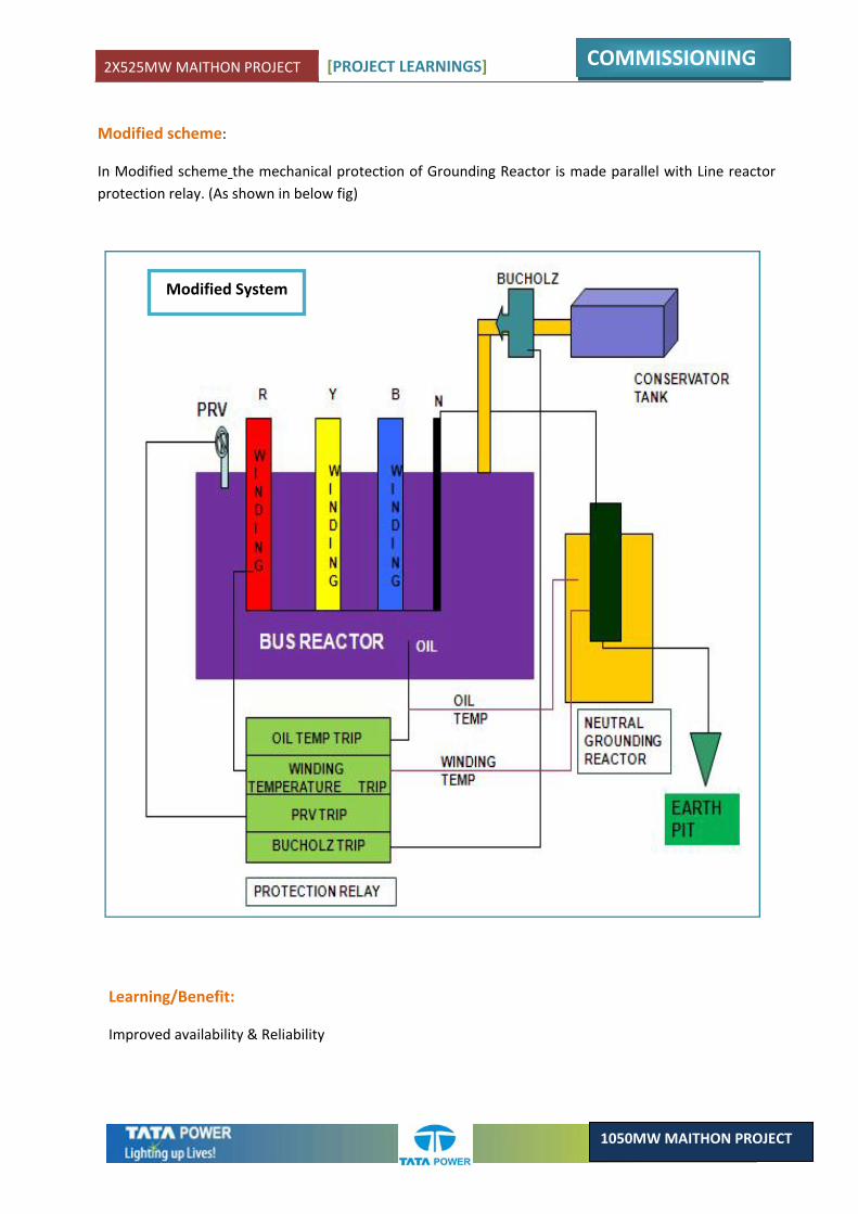
2X525MW MAITHON PROJECT [PROJECT LEARNINGS]
COMMISSIONING
1050MW MAITHON PROJECT
Modified scheme:
In Modified scheme the mechanical protection of Grounding Reactor is made parallel with Line reactor protection relay. (As shown in below fig)
Modified System
Learning/Benefit:
Improved availability & Reliability
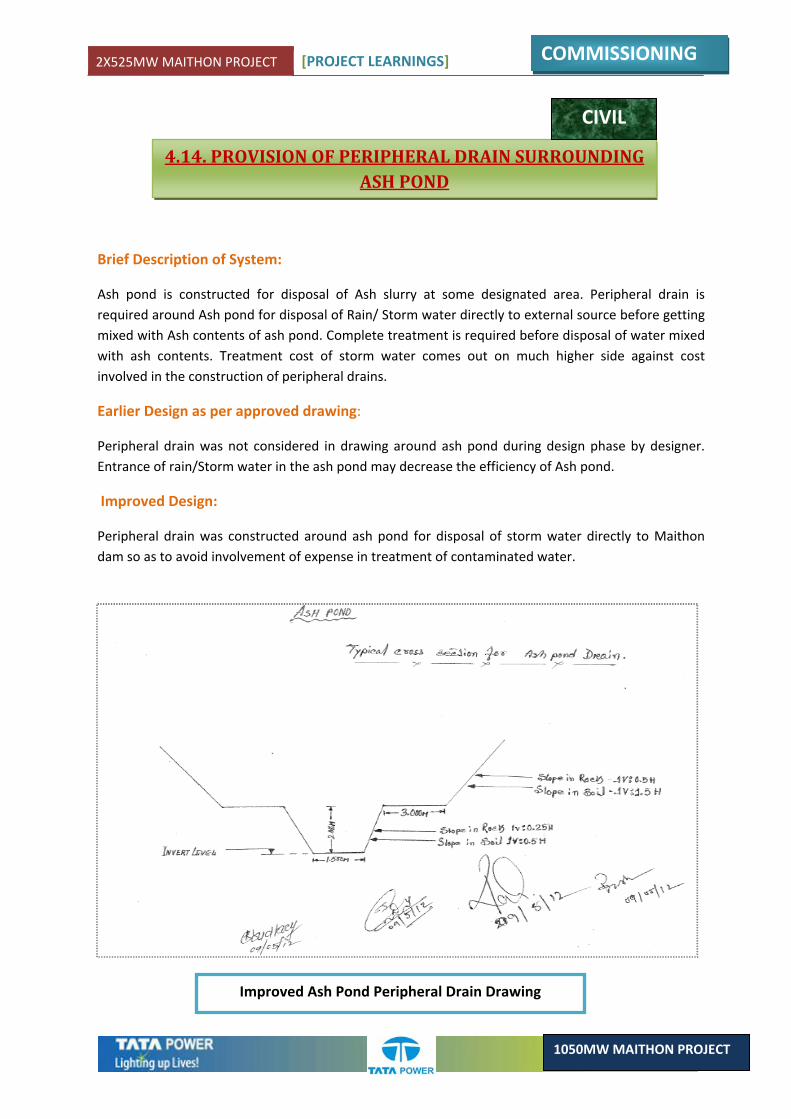
2X525MW MAITHON PROJECT [PROJECT LEARNINGS]
COMMISSIONING
1050MW MAITHON PROJECT
4.14. PROVISION OF PERIPHERAL DRAIN SURROUNDING ASH POND
CIVIL
Brief Description of System:
Ash pond is constructed for disposal of Ash slurry at some designated area. Peripheral drain is required around Ash pond for disposal of Rain/ Storm water directly to external source before getting mixed with Ash contents of ash pond. Complete treatment is required before disposal of water mixed with ash contents. Treatment cost of storm water comes out on much higher side against cost involved in the construction of peripheral drains.
Earlier Design as per approved drawing:
Peripheral drain was not considered in drawing around ash pond during design phase by designer. Entrance of rain/Storm water in the ash pond may decrease the efficiency of Ash pond.
Improved Design:
Peripheral drain was constructed around ash pond for disposal of storm water directly to Maithon dam so as to avoid involvement of expense in treatment of contaminated water.
Improved Ash Pond Peripheral Drain Drawing
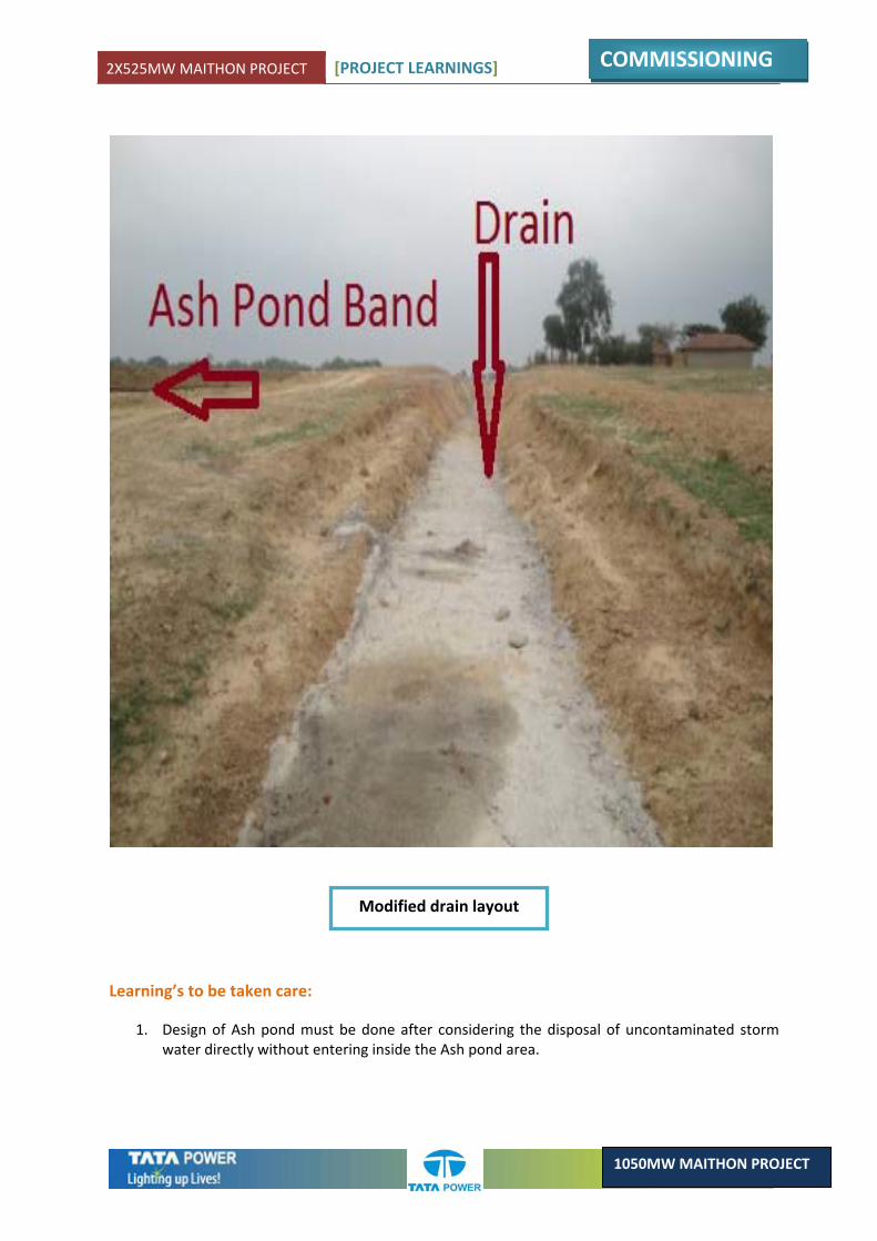
2X525MW MAITHON PROJECT [PROJECT LEARNINGS]
COMMISSIONING
1050MW MAITHON PROJECT
Learning’s to be taken care:
1. Design of Ash pond must be done after considering the disposal of uncontaminated storm water directly without entering inside the Ash pond area.
Modified drain layout
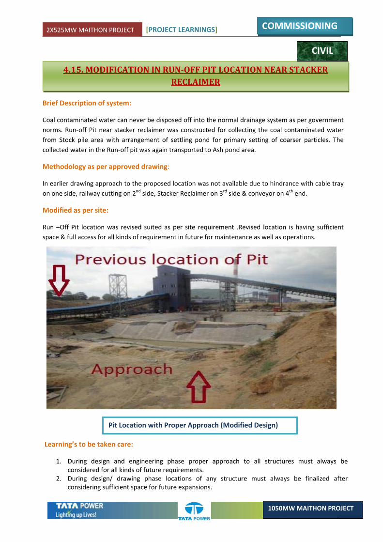
2X525MW MAITHON PROJECT [PROJECT LEARNINGS]
COMMISSIONING
1050MW MAITHON PROJECT
4.15. MODIFICATION IN RUNOFF PIT LOCATION NEAR STACKER RECLAIMER
CIVIL
Brief Description of system:
Coal contaminated water can never be disposed off into the normal drainage system as per government norms. Run‐off Pit near stacker reclaimer was constructed for collecting the coal contaminated water from Stock pile area with arrangement of settling pond for primary setting of coarser particles. The collected water in the Run‐off pit was again transported to Ash pond area.
Methodology as per approved drawing:
In earlier drawing approach to the proposed location was not available due to hindrance with cable tray on one side, railway cutting on 2nd side, Stacker Reclaimer on 3rd side & conveyor on 4th end.
Modified as per site:
Run –Off Pit location was revised suited as per site requirement .Revised location is having sufficient space & full access for all kinds of requirement in future for maintenance as well as operations.
Learning’s to be taken care:
1. During design and engineering phase proper approach to all structures must always be considered for all kinds of future requirements.
2. During design/ drawing phase locations of any structure must always be finalized after considering sufficient space for future expansions.
Pit Location with Proper Approach (Modified Design)
2X525MW MAITHON PROJECT [PROJECT LEARNINGS]
COMMISSIONING
1050MW MAITHON PROJECT
4.16. LOWER RATING OF NGR CONNECTING CABLES FOR STATION TRANSFORMER
ELECTRICAL
Description:
Station transformer Installed at 400Kv switchyard is of 80Mva rating with two secondary outgoings of 6.6Kv & 11Kv grade. The Low Voltage side neutral of both 6.6Kv & 11Kv windings are grounded through two separate Neutral Grounding Resistors (NGRs) of suitable ratings. These resistors help in passing of fault currents during any fault in the equipment or connecting cables. These NGRs are connected to the Station Transformer LV ‐ Neutral earth by two separate cables.
Original scheme:
The approved scheme showed a 440 Volts cable connecting the transformer neutral earth strip with the NGR. After commissioning of the transformer & subsequent charging of the downstream equipments it was found that the fault current being generated was quiet high.
Improved Scheme:
As per calculation it was found that cable to be 6.6kV grade, not 440V grade cable was replaced with 6.6kV grade cable.
Learning:
It was concluded that during designing stage; the level of fault currents to be generated by downstream equipments were not properly assessed. This led to the final approval of 440 Volts cable for NGR connection. This learning was implemented for the Unit # 2 Station Transformer.
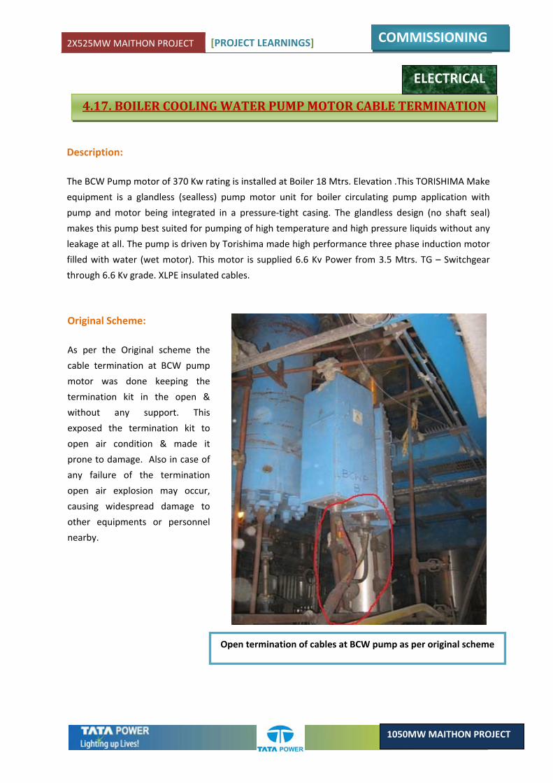
2X525MW MAITHON PROJECT [PROJECT LEARNINGS]
COMMISSIONING
1050MW MAITHON PROJECT
4.17. BOILER COOLING WATER PUMP MOTOR CABLE TERMINATION
ELECTRICAL
Description:
The BCW Pump motor of 370 Kw rating is installed at Boiler 18 Mtrs. Elevation .This TORISHIMA Make
equipment is a glandless (sealless) pump motor unit for boiler circulating pump application with
pump and motor being integrated in a pressure‐tight casing. The glandless design (no shaft seal)
makes this pump best suited for pumping of high temperature and high pressure liquids without any
leakage at all. The pump is driven by Torishima made high performance three phase induction motor
filled with water (wet motor). This motor is supplied 6.6 Kv Power from 3.5 Mtrs. TG – Switchgear
through 6.6 Kv grade. XLPE insulated cables.
Original Scheme:
As per the Original scheme the
cable termination at BCW pump
motor was done keeping the
termination kit in the open &
without any support. This
exposed the termination kit to
open air condition & made it
prone to damage. Also in case of
any failure of the termination
open air explosion may occur,
causing widespread damage to
other equipments or personnel
nearby.
Open termination of cables at BCW pump as per original scheme

2X525MW MAITHON PROJECT [PROJECT LEARNINGS]
COMMISSIONING
1050MW MAITHON PROJECT
Improved Scheme:
Considering the Safety Aspects &
Standard practices, it was
decided to put a cable
termination end box. This was
done by the Site Electrical Team
by designing a suitable box with
the help of a Local vendor –
fabricator. This box was so
designed that it can cover the
termination & can easily be
mounted on the existing
structure. This improvement has
enhanced the Safety & aesthetic
aspect of the equipment.
Picture of cable termination end box at BCW pump
Learning:
Following points should be taken care of during design:
1. Proper cable entry to equipments taking care of site requirements, electric regulation, safety of surrounding equipments and personnel who may be working in those areas.
2. Also special care should be taken about the location of HT cable termination.
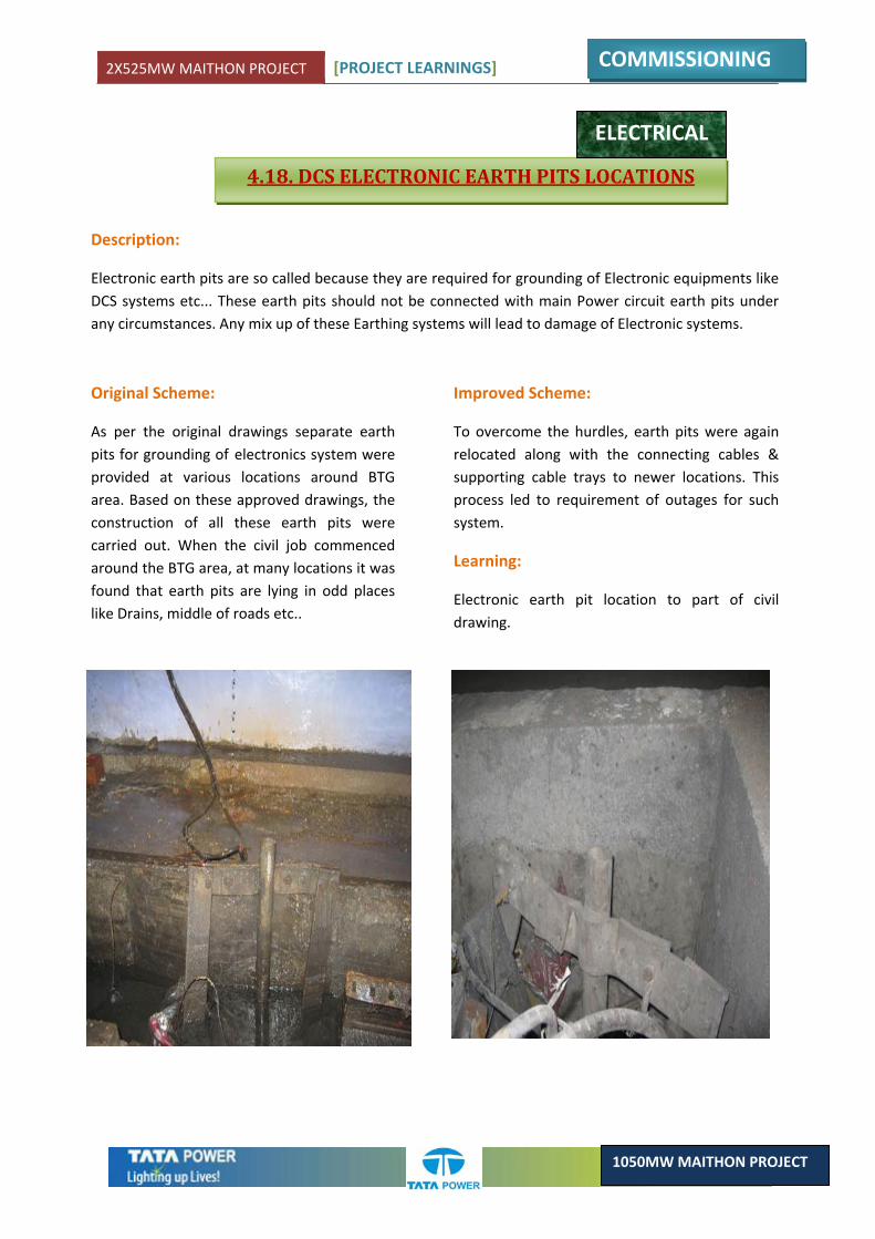
2X525MW MAITHON PROJECT [PROJECT LEARNINGS]
COMMISSIONING
1050MW MAITHON PROJECT
4.18. DCS ELECTRONIC EARTH PITS LOCATIONS
ELECTRICAL
Description:
Electronic earth pits are so called because they are required for grounding of Electronic equipments like DCS systems etc... These earth pits should not be connected with main Power circuit earth pits under any circumstances. Any mix up of these Earthing systems will lead to damage of Electronic systems.
Original Scheme:
As per the original drawings separate earth pits for grounding of electronics system were provided at various locations around BTG area. Based on these approved drawings, the construction of all these earth pits were carried out. When the civil job commenced around the BTG area, at many locations it was found that earth pits are lying in odd places like Drains, middle of roads etc..
Improved Scheme:
To overcome the hurdles, earth pits were again relocated along with the connecting cables & supporting cable trays to newer locations. This process led to requirement of outages for such system.
Learning:
Electronic earth pit location to part of civil drawing.

2X525MW MAITHON PROJECT [PROJECT LEARNINGS]
COMMISSIONING
1050MW MAITHON PROJECT
4.19. PROVISION OF COOLING TOWER SECONDARY & TERTIARY DRAINS
CIVIL
Brief Description:
Cooling tower of a thermal power plant is constructed for controlling the temperature of the water to recycle the same in the plant. During operation of cooling tower continuous fall of water takes place from some height which will facilitate early cooling of water.
Earlier Design as per drawing:
In the approved drawing secondary & tertiary drains were not considered for disposal of excess water of that area.
Improved Design as per site:
Secondary & tertiary drains connecting main plant drains were constructed around cooling tower so as to avoid water logging in the area & to facilitate easy discharge of water from surrounding areas.
Learning’s to be taken care:
1. During design of Cooling tower arrangement for disposal of excess water to main plant drains must be considered.
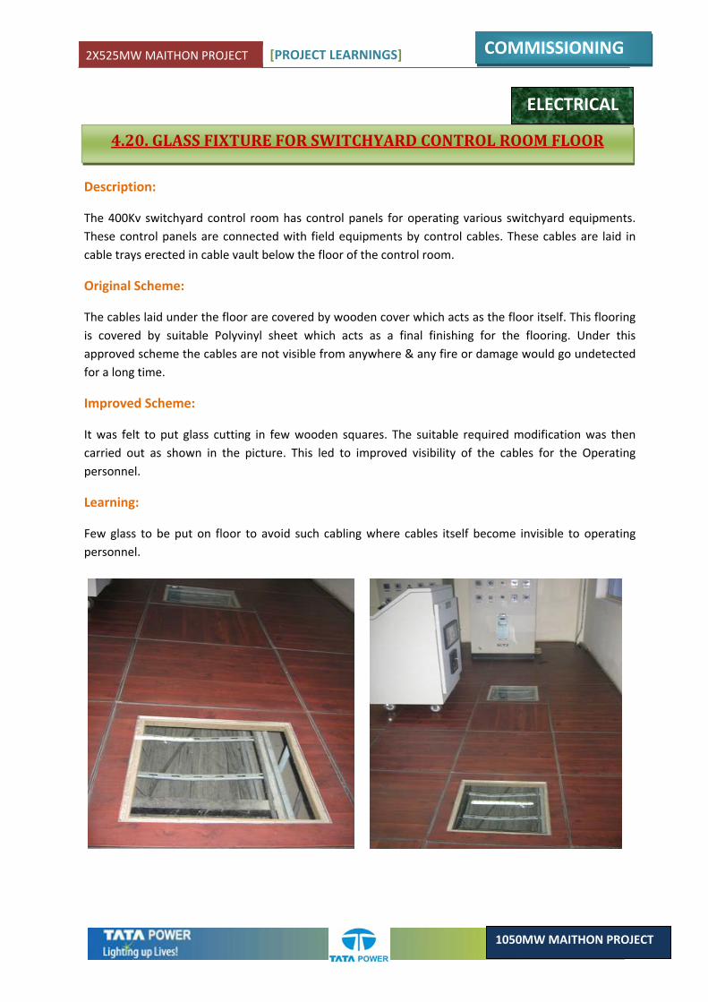
2X525MW MAITHON PROJECT [PROJECT LEARNINGS]
COMMISSIONING
1050MW MAITHON PROJECT
4.20. GLASS FIXTURE FOR SWITCHYARD CONTROL ROOM FLOOR
ELECTRICAL
Description:
The 400Kv switchyard control room has control panels for operating various switchyard equipments. These control panels are connected with field equipments by control cables. These cables are laid in cable trays erected in cable vault below the floor of the control room.
Original Scheme:
The cables laid under the floor are covered by wooden cover which acts as the floor itself. This flooring is covered by suitable Polyvinyl sheet which acts as a final finishing for the flooring. Under this approved scheme the cables are not visible from anywhere & any fire or damage would go undetected for a long time.
Improved Scheme:
It was felt to put glass cutting in few wooden squares. The suitable required modification was then carried out as shown in the picture. This led to improved visibility of the cables for the Operating personnel.
Learning:
Few glass to be put on floor to avoid such cabling where cables itself become invisible to operating personnel.
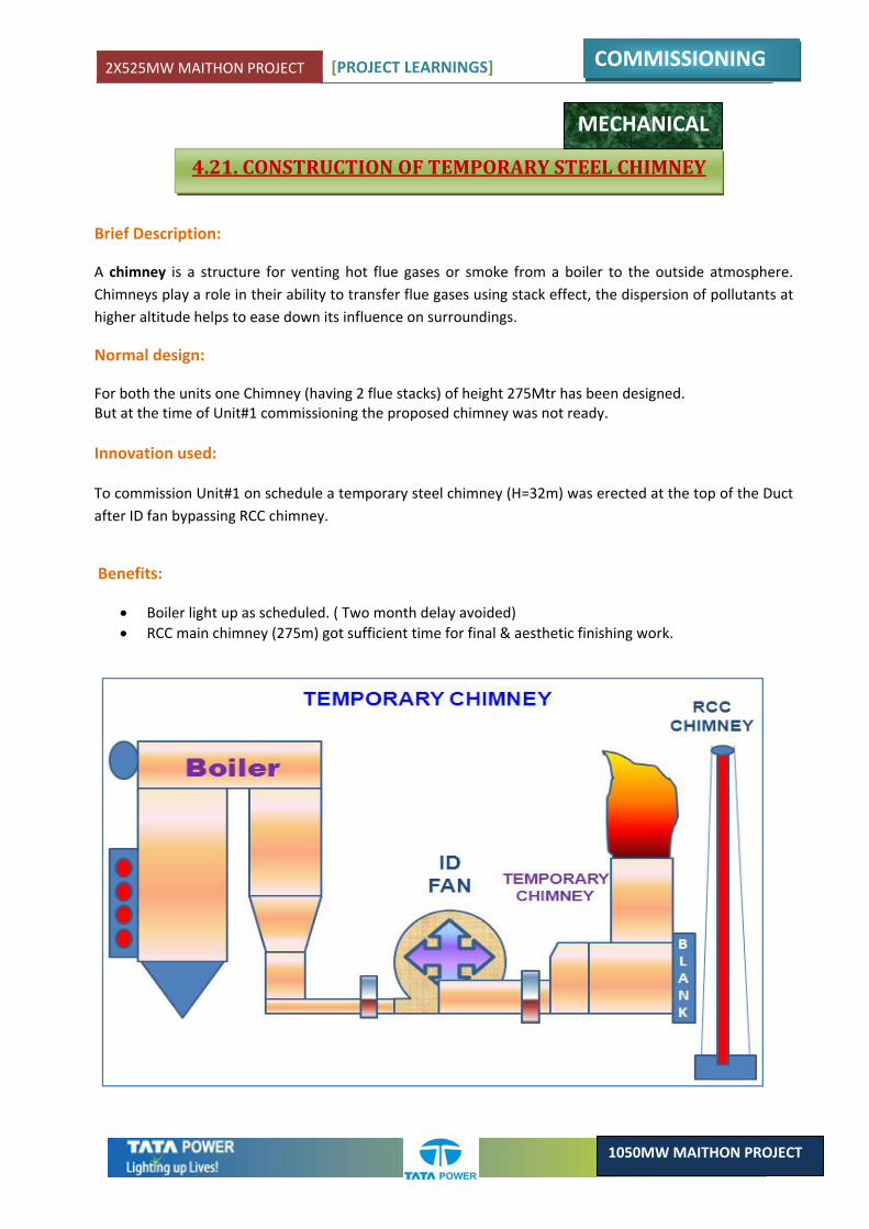
2X525MW MAITHON PROJECT [PROJECT LEARNINGS]
COMMISSIONING
1050MW MAITHON PROJECT
4.21. CONSTRUCTION OF TEMPORARY STEEL CHIMNEY
Brief Description:
A chimney is a structure for venting hot flue gases or smoke from a boiler to the outside atmosphere. Chimneys play a role in their ability to transfer flue gases using stack effect, the dispersion of pollutants at higher altitude helps to ease down its influence on surroundings.
Normal design:
For both the units one Chimney (having 2 flue stacks) of height 275Mtr has been designed. But at the time of Unit#1 commissioning the proposed chimney was not ready. Innovation used: To commission Unit#1 on schedule a temporary steel chimney (H=32m) was erected at the top of the Duct after ID fan bypassing RCC chimney.
Benefits:
• Boiler light up as scheduled. ( Two month delay avoided) • RCC main chimney (275m) got sufficient time for final & aesthetic finishing work.
MECHANICAL
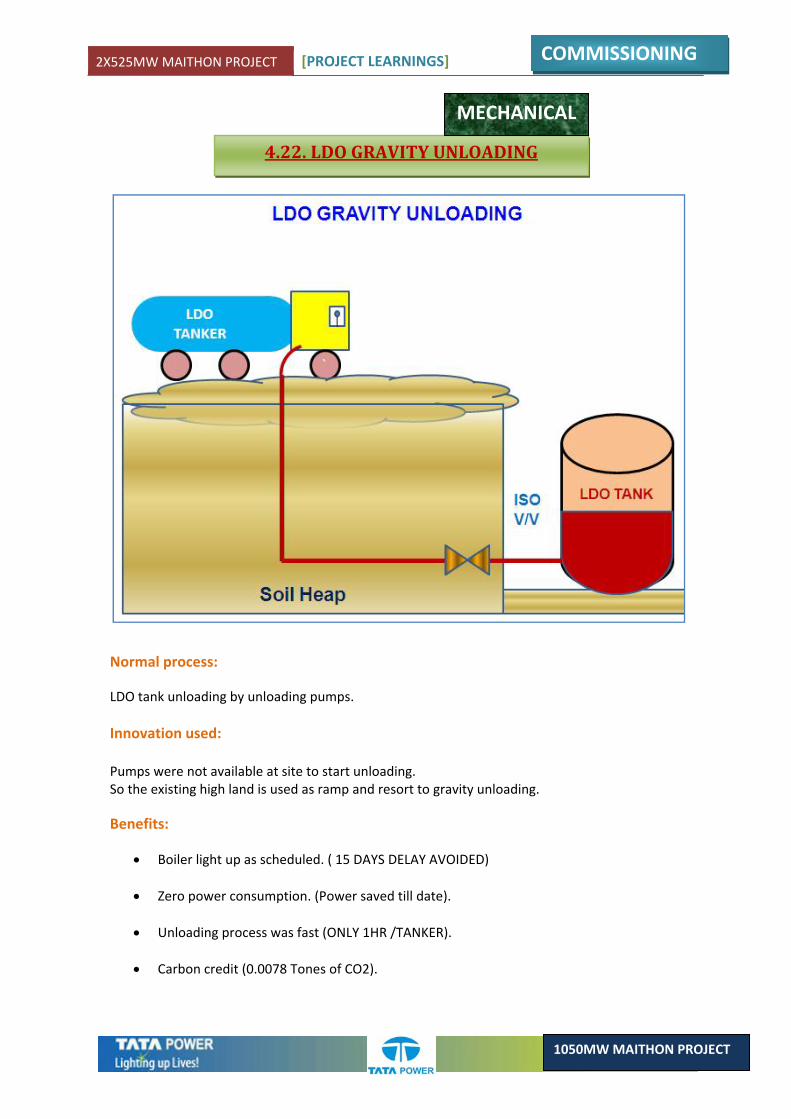
2X525MW MAITHON PROJECT [PROJECT LEARNINGS]
COMMISSIONING
1050MW MAITHON PROJECT
4.22. LDO GRAVITY UNLOADING
MECHANICAL
Normal process:
LDO tank unloading by unloading pumps. Innovation used: Pumps were not available at site to start unloading. So the existing high land is used as ramp and resort to gravity unloading.
Benefits:
• Boiler light up as scheduled. ( 15 DAYS DELAY AVOIDED)
• Zero power consumption. (Power saved till date).
• Unloading process was fast (ONLY 1HR /TANKER).
• Carbon credit (0.0078 Tones of CO2).
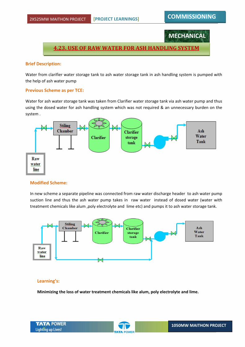
2X525MW MAITHON PROJECT [PROJECT LEARNINGS]
COMMISSIONING
1050MW MAITHON PROJECT
Brief Description:
Water from clarifier water storage tank to ash water storage tank in ash handling system is pumped with the help of ash water pump
Previous Scheme as per TCE:
Water for ash water storage tank was taken from Clarifier water storage tank via ash water pump and thus using the dosed water for ash handling system which was not required & an unnecessary burden on the system .
Modified Scheme:
In new scheme a separate pipeline was connected from raw water discharge header to ash water pump suction line and thus the ash water pump takes in raw water instead of dosed water (water with treatment chemicals like alum ,poly electrolyte and lime etc) and pumps it to ash water storage tank.
Learning’s:
Minimizing the loss of water treatment chemicals like alum, poly electrolyte and lime.
MECHANICAL
4.23. USE OF RAW WATER FOR ASH HANDLING SYSTEM
CHAPTER 5CRITICAL LEARNING

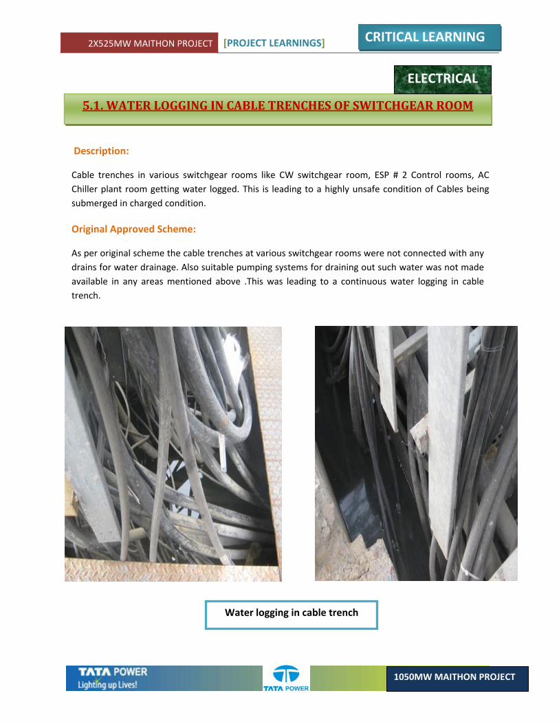
2X525MW MAITHON PROJECT [PROJECT LEARNINGS]
CRITICAL LEARNING
1050MW MAITHON PROJECT
5.1. WATER LOGGING IN CABLE TRENCHES OF SWITCHGEAR ROOM
ELECTRICAL
Description:
Cable trenches in various switchgear rooms like CW switchgear room, ESP # 2 Control rooms, AC Chiller plant room getting water logged. This is leading to a highly unsafe condition of Cables being submerged in charged condition.
Original Approved Scheme:
As per original scheme the cable trenches at various switchgear rooms were not connected with any drains for water drainage. Also suitable pumping systems for draining out such water was not made available in any areas mentioned above .This was leading to a continuous water logging in cable trench.
Water logging in cable trench
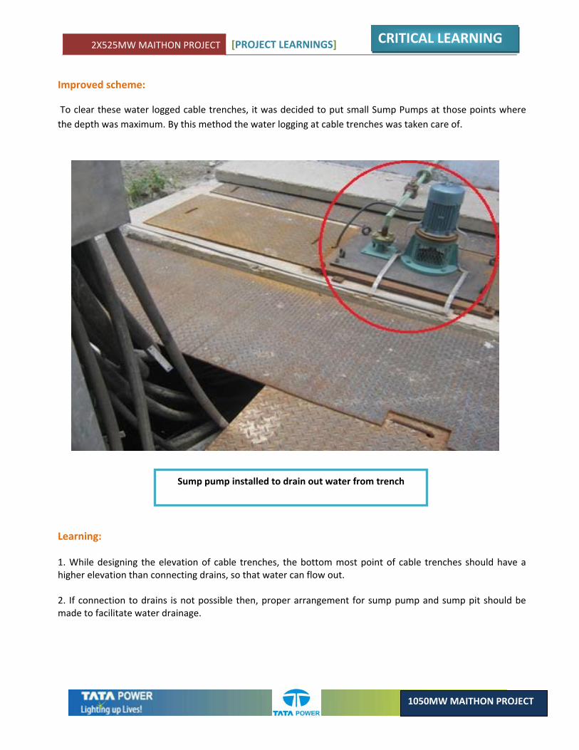
2X525MW MAITHON PROJECT [PROJECT LEARNINGS]
CRITICAL LEARNING
1050MW MAITHON PROJECT
Improved scheme:
To clear these water logged cable trenches, it was decided to put small Sump Pumps at those points where the depth was maximum. By this method the water logging at cable trenches was taken care of.
Sump pump installed to drain out water from trench
Learning: 1. While designing the elevation of cable trenches, the bottom most point of cable trenches should have a higher elevation than connecting drains, so that water can flow out. 2. If connection to drains is not possible then, proper arrangement for sump pump and sump pit should be made to facilitate water drainage.
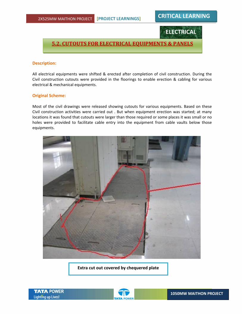
2X525MW MAITHON PROJECT [PROJECT LEARNINGS]
CRITICAL LEARNING
1050MW MAITHON PROJECT
5.2. CUTOUTS FOR ELECTRICAL EQUIPMENTS & PANELS
ELECTRICAL
Description: All electrical equipments were shifted & erected after completion of civil construction. During the Civil construction cutouts were provided in the floorings to enable erection & cabling for various electrical & mechanical equipments. Original Scheme: Most of the civil drawings were released showing cutouts for various equipments. Based on these Civil construction activities were carried out . But when equipment erection was started; at many locations it was found that cutouts were larger than those required or some places it was small or no holes were provided to facilitate cable entry into the equipment from cable vaults below those equipments.
Extra cut out covered by chequered plate
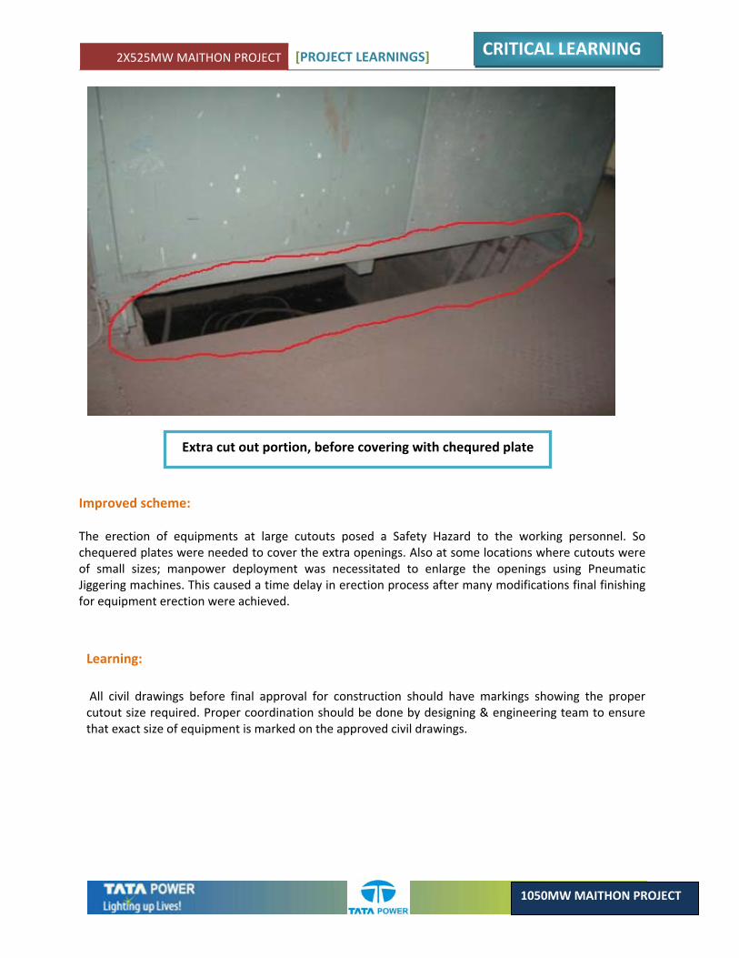
2X525MW MAITHON PROJECT [PROJECT LEARNINGS]
CRITICAL LEARNING
1050MW MAITHON PROJECT
Extra cut out portion, before covering with chequred plate
Improved scheme: The erection of equipments at large cutouts posed a Safety Hazard to the working personnel. So chequered plates were needed to cover the extra openings. Also at some locations where cutouts were of small sizes; manpower deployment was necessitated to enlarge the openings using Pneumatic Jiggering machines. This caused a time delay in erection process after many modifications final finishing for equipment erection were achieved.
Learning: All civil drawings before final approval for construction should have markings showing the proper cutout size required. Proper coordination should be done by designing & engineering team to ensure that exact size of equipment is marked on the approved civil drawings.
2X525MW MAITHON PROJECT [PROJECT LEARNINGS]
CRITICAL LEARNING
1050MW MAITHON PROJECT
5.3. ALTERNATIVE METHOD FOR AUXILIARY COOLING SYSTEM
MECHANICAL
Brief Description: A plate heat exchanger is a type of heat exchanger that uses metal plates to transfer heat between two fluids
Previous Scheme as per TCE: The DMCW (Demineralised Cooling Water) pump collects hot water from auxiliaries and feeds the same into PHE (Plate Heat Exchanger) and the cooled water coming out from PHE is used for cooling the same auxiliaries. The above hot water entering the PHE is cooled with the help of ACW pump which feeds the cooled water from CW line to PHE and the hot water coming out from PHE is taken back to cooling tower via CW line.
Modified Scheme:
• A separate line was connected to PHE from service water pump discharge header and the return hot water was dumped either to forebay/guard pond.
• Thus auxilary cooling is carried out in the absence of CW & ACW pump. The method can be
adopted as a standby system in case of CW/ACW pump failure and also power saving can be achieved.
Learning’s: During commissioning activities where auxiliary cooling is mandatory and by that time CW system cannot be made ready so Engineering/Design Department has to come up with some alternate solution and the above scheme can be incorporated in future projects as a contingency plan.
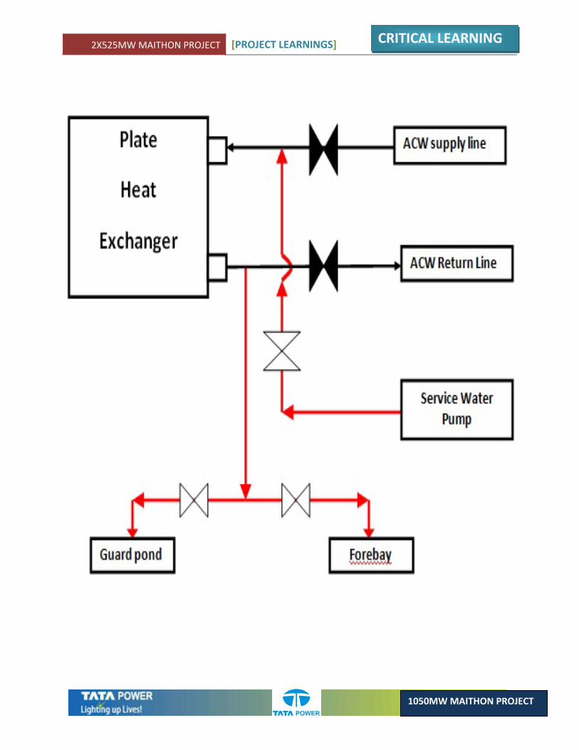
2X525MW MAITHON PROJECT [PROJECT LEARNINGS]
CRITICAL LEARNING
1050MW MAITHON PROJECT
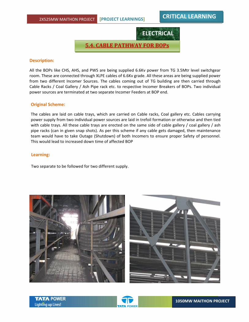
2X525MW MAITHON PROJECT [PROJECT LEARNINGS]
CRITICAL LEARNING
1050MW MAITHON PROJECT
5.4. CABLE PATHWAY FOR BOPs
ELECTRICAL
Description:
All the BOPs like CHS, AHS, and PWS are being supplied 6.6Kv power from TG 3.5Mtr level switchgear room. These are connected through XLPE cables of 6.6Kv grade. All these areas are being supplied power from two different Incomer Sources. The cables coming out of TG building are then carried through Cable Racks / Coal Gallery / Ash Pipe rack etc. to respective Incomer Breakers of BOPs. Two individual power sources are terminated at two separate Incomer Feeders at BOP end.
Original Scheme:
The cables are laid on cable trays, which are carried on Cable racks, Coal gallery etc. Cables carrying power supply from two individual power sources are laid in trefoil formation or otherwise and then tied with cable trays. All these cable trays are erected on the same side of cable gallery / coal gallery / ash pipe racks (can in given snap shots). As per this scheme if any cable gets damaged, then maintenance team would have to take Outage (Shutdown) of both Incomers to ensure proper Safety of personnel. This would lead to increased down time of affected BOP
Learning: Two separate to be followed for two different supply.
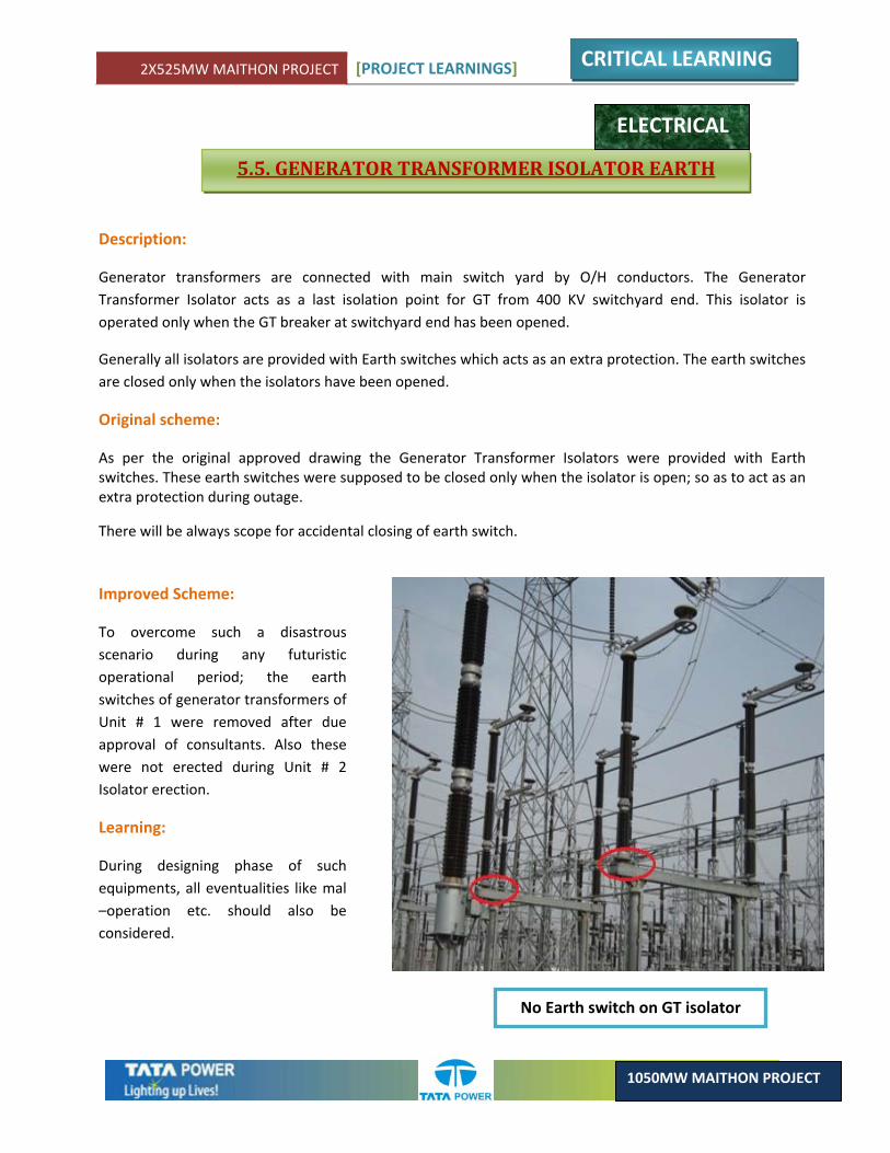
2X525MW MAITHON PROJECT [PROJECT LEARNINGS]
CRITICAL LEARNING
1050MW MAITHON PROJECT
5.5. GENERATOR TRANSFORMER ISOLATOR EARTH
ELECTRICAL
Description:
Generator transformers are connected with main switch yard by O/H conductors. The Generator Transformer Isolator acts as a last isolation point for GT from 400 KV switchyard end. This isolator is operated only when the GT breaker at switchyard end has been opened.
Generally all isolators are provided with Earth switches which acts as an extra protection. The earth switches are closed only when the isolators have been opened.
Original scheme:
As per the original approved drawing the Generator Transformer Isolators were provided with Earth switches. These earth switches were supposed to be closed only when the isolator is open; so as to act as an extra protection during outage.
There will be always scope for accidental closing of earth switch.
Improved Scheme:
To overcome such a disastrous scenario during any futuristic operational period; the earth switches of generator transformers of Unit # 1 were removed after due approval of consultants. Also these were not erected during Unit # 2 Isolator erection.
Learning:
During designing phase of such equipments, all eventualities like mal –operation etc. should also be considered.
No Earth switch on GT isolator
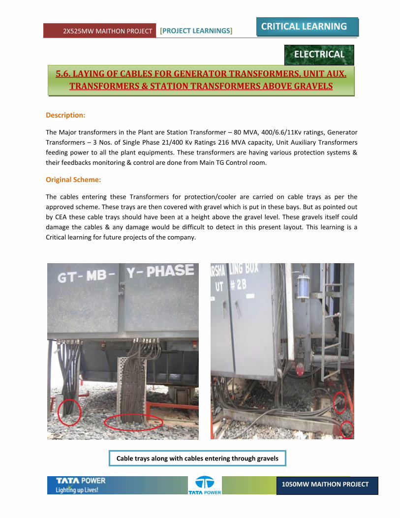
2X525MW MAITHON PROJECT [PROJECT LEARNINGS]
CRITICAL LEARNING
1050MW MAITHON PROJECT
5.6. LAYING OF CABLES FOR GENERATOR TRANSFORMERS, UNIT AUX. TRANSFORMERS & STATION TRANSFORMERS ABOVE GRAVELS
ELECTRICAL
Description:
The Major transformers in the Plant are Station Transformer – 80 MVA, 400/6.6/11Kv ratings, Generator Transformers – 3 Nos. of Single Phase 21/400 Kv Ratings 216 MVA capacity, Unit Auxiliary Transformers feeding power to all the plant equipments. These transformers are having various protection systems & their feedbacks monitoring & control are done from Main TG Control room.
Original Scheme:
The cables entering these Transformers for protection/cooler are carried on cable trays as per the approved scheme. These trays are then covered with gravel which is put in these bays. But as pointed out by CEA these cable trays should have been at a height above the gravel level. These gravels itself could damage the cables & any damage would be difficult to detect in this present layout. This learning is a Critical learning for future projects of the company.
Cable trays along with cables entering through gravels
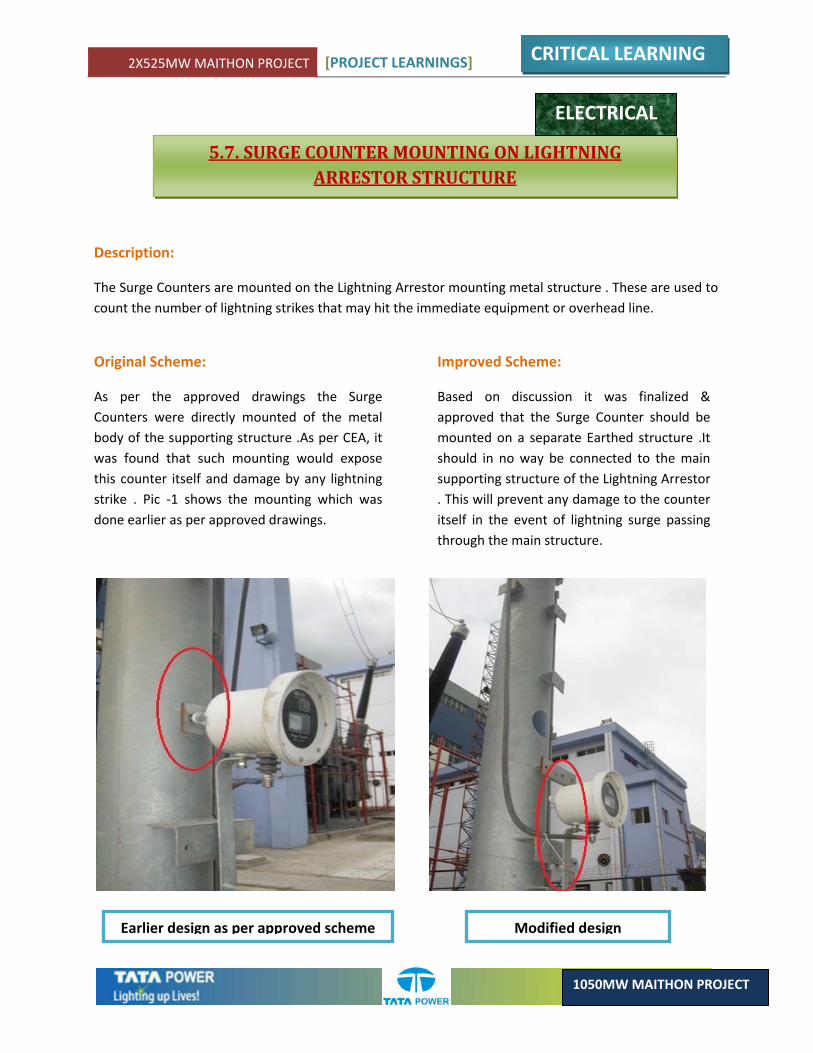
2X525MW MAITHON PROJECT [PROJECT LEARNINGS]
CRITICAL LEARNING
1050MW MAITHON PROJECT
5.7. SURGE COUNTER MOUNTING ON LIGHTNING ARRESTOR STRUCTURE
ELECTRICAL
Description:
The Surge Counters are mounted on the Lightning Arrestor mounting metal structure . These are used to count the number of lightning strikes that may hit the immediate equipment or overhead line.
Original Scheme:
As per the approved drawings the Surge Counters were directly mounted of the metal body of the supporting structure .As per CEA, it was found that such mounting would expose this counter itself and damage by any lightning strike . Pic ‐1 shows the mounting which was done earlier as per approved drawings.
Improved Scheme:
Based on discussion it was finalized & approved that the Surge Counter should be mounted on a separate Earthed structure .It should in no way be connected to the main supporting structure of the Lightning Arrestor . This will prevent any damage to the counter itself in the event of lightning surge passing through the main structure.
Earlier design as per approved scheme Modified design
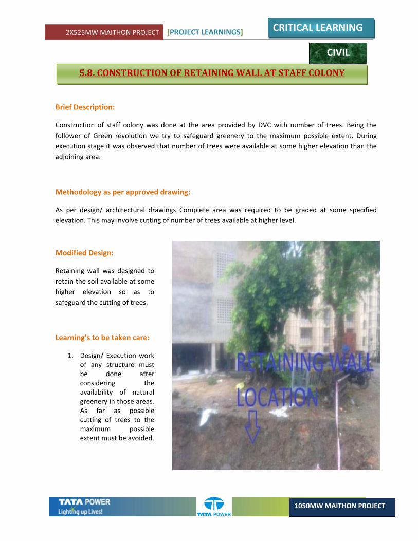
2X525MW MAITHON PROJECT [PROJECT LEARNINGS]
CRITICAL LEARNING
1050MW MAITHON PROJECT
5.8. CONSTRUCTION OF RETAINING WALL AT STAFF COLONY
Brief Description:
Construction of staff colony was done at the area provided by DVC with number of trees. Being the follower of Green revolution we try to safeguard greenery to the maximum possible extent. During execution stage it was observed that number of trees were available at some higher elevation than the adjoining area.
Methodology as per approved drawing:
As per design/ architectural drawings Complete area was required to be graded at some specified elevation. This may involve cutting of number of trees available at higher level.
Modified Design:
Retaining wall was designed to retain the soil available at some higher elevation so as to safeguard the cutting of trees.
Learning’s to be taken care:
1. Design/ Execution work of any structure must be done after considering the availability of natural greenery in those areas. As far as possible cutting of trees to the maximum possible extent must be avoided.
CIVIL
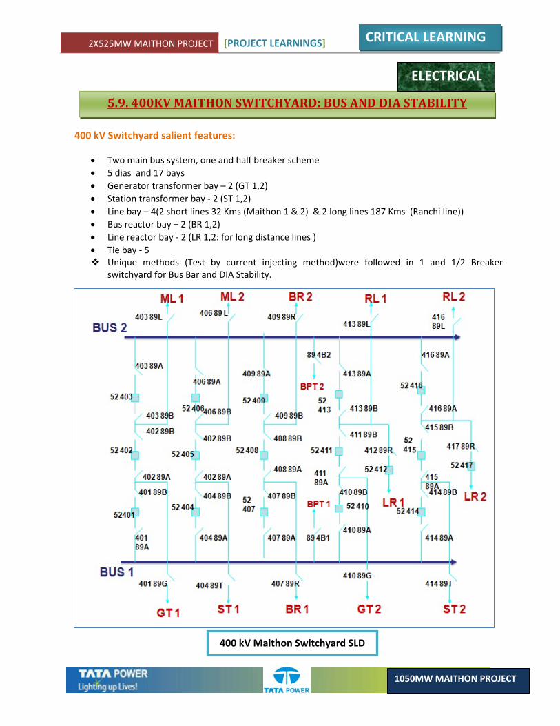
2X525MW MAITHON PROJECT [PROJECT LEARNINGS]
CRITICAL LEARNING
1050MW MAITHON PROJECT
5.9. 400KV MAITHON SWITCHYARD: BUS AND DIA STABILITY
ELECTRICAL
400 kV Switchyard salient features:
• Two main bus system, one and half breaker scheme • 5 dias and 17 bays • Generator transformer bay – 2 (GT 1,2) • Station transformer bay ‐ 2 (ST 1,2) • Line bay – 4(2 short lines 32 Kms (Maithon 1 & 2) & 2 long lines 187 Kms (Ranchi line)) • Bus reactor bay – 2 (BR 1,2) • Line reactor bay ‐ 2 (LR 1,2: for long distance lines ) • Tie bay ‐ 5
Unique methods (Test by current injecting method)were followed in 1 and 1/2 Breaker switchyard for Bus Bar and DIA Stability.
400 kV Maithon Switchyard SLD
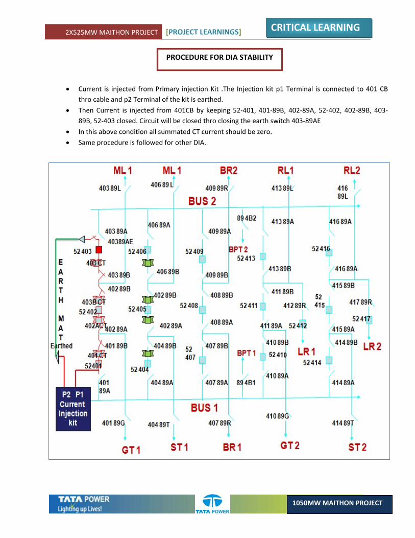
2X525MW MAITHON PROJECT [PROJECT LEARNINGS]
CRITICAL LEARNING
1050MW MAITHON PROJECT
PROCEDURE FOR DIA STABILITY
• Current is injected from Primary injection Kit .The Injection kit p1 Terminal is connected to 401 CB thro cable and p2 Terminal of the kit is earthed.
• Then Current is injected from 401CB by keeping 52‐401, 401‐89B, 402‐89A, 52‐402, 402‐89B, 403‐89B, 52‐403 closed. Circuit will be closed thro closing the earth switch 403‐89AE
• In this above condition all summated CT current should be zero.
• Same procedure is followed for other DIA.
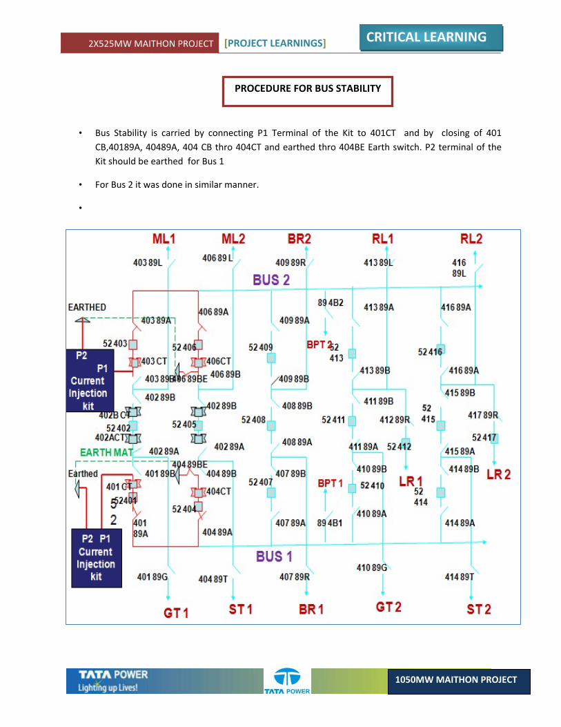
2X525MW MAITHON PROJECT [PROJECT LEARNINGS]
CRITICAL LEARNING
1050MW MAITHON PROJECT
PROCEDURE FOR BUS STABILITY
• Bus Stability is carried by connecting P1 Terminal of the Kit to 401CT and by closing of 401 CB,40189A, 40489A, 404 CB thro 404CT and earthed thro 404BE Earth switch. P2 terminal of the Kit should be earthed for Bus 1
• For Bus 2 it was done in similar manner.
•
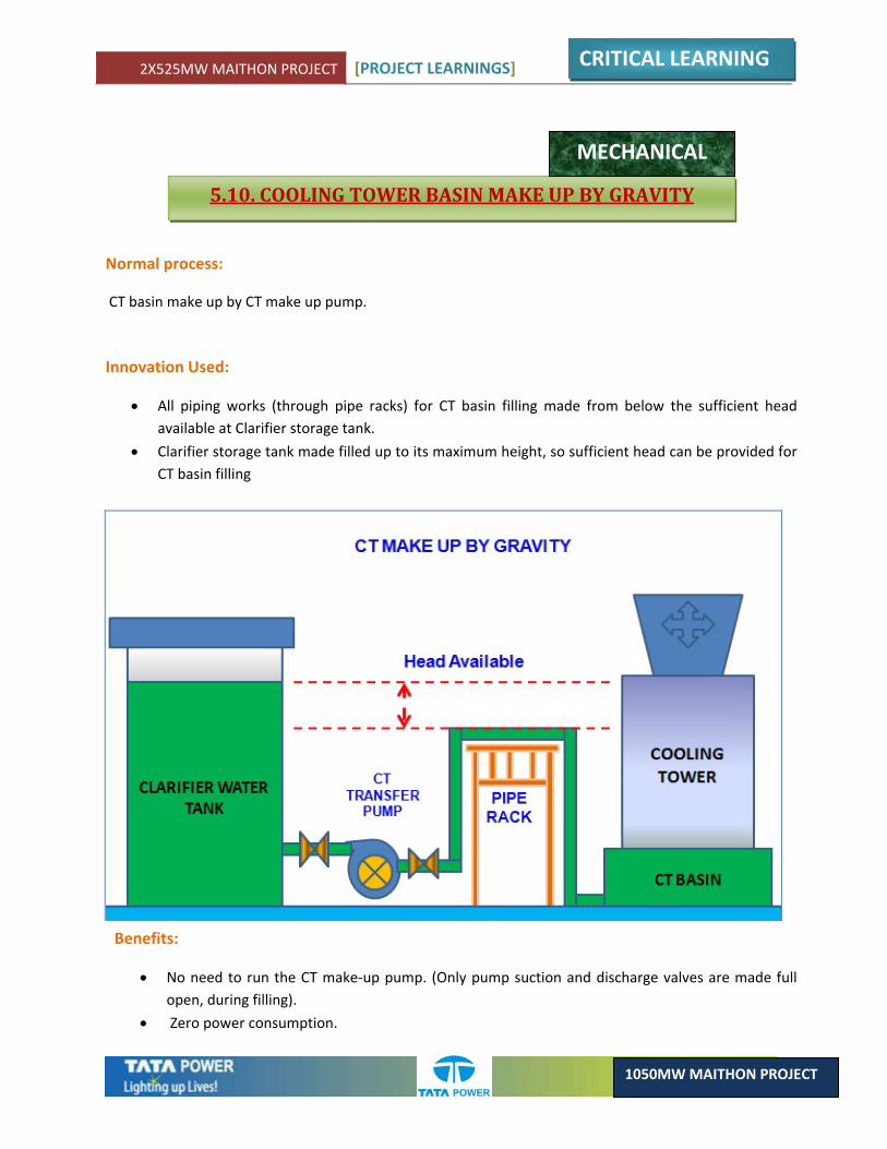
2X525MW MAITHON PROJECT [PROJECT LEARNINGS]
CRITICAL LEARNING
1050MW MAITHON PROJECT
Normal process:
CT basin make up by CT make up pump.
Innovation Used:
• All piping works (through pipe racks) for CT basin filling made from below the sufficient head available at Clarifier storage tank.
• Clarifier storage tank made filled up to its maximum height, so sufficient head can be provided for CT basin filling
Benefits:
• No need to run the CT make‐up pump. (Only pump suction and discharge valves are made full open, during filling).
• Zero power consumption.
5.10. COOLING TOWER BASIN MAKE UP BY GRAVITY
MECHANICAL
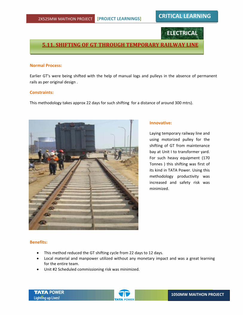
2X525MW MAITHON PROJECT [PROJECT LEARNINGS]
CRITICAL LEARNING
1050MW MAITHON PROJECT
ELECTRICAL
5.11. SHIFTING OF GT THROUGH TEMPORARY RAILWAY LINE
Normal Process:
Earlier GT's were being shifted with the help of manual logs and pulleys in the absence of permanent rails as per original design .
Constraints:
This methodology takes approx 22 days for such shifting for a distance of around 300 mtrs).
Innovative:
Laying temporary railway line and using motorized pulley for the shifting of GT from maintenance bay at Unit I to transformer yard. For such heavy equipment (170 Tonnes ) this shifting was first of its kind in TATA Power. Using this methodology productivity was increased and safety risk was minimized.
Benefits:
• This method reduced the GT shifting cycle from 22 days to 12 days. • Local material and manpower utilized without any monetary impact and was a great learning
for the entire team. • Unit #2 Scheduled commissioning risk was minimized.
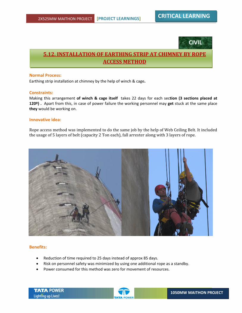
2X525MW MAITHON PROJECT [PROJECT LEARNINGS]
CRITICAL LEARNING
1050MW MAITHON PROJECT
CIVIL
5.12. INSTALLATION OF EARTHING STRIP AT CHIMNEY BY ROPE ACCESS METHOD
Normal Process: Earthing strip installation at chimney by the help of winch & cage. Constraints: Making this arrangement of winch & cage itself takes 22 days for each section (3 sections placed at 120º) . Apart from this, in case of power failure the working personnel may get stuck at the same place they would be working on. Innovative idea:
Rope access method was implemented to do the same job by the help of Web Ceiling Belt. It included the usage of 5 layers of belt (capacity 2 Ton each), fall arrester along with 3 layers of rope.
Benefits:
• Reduction of time required to 25 days instead of approx 85 days. • Risk on personnel safety was minimized by using one additional rope as a standby. • Power consumed for this method was zero for movement of resources.


CHAPTER 6:HUMAN RESOURCE

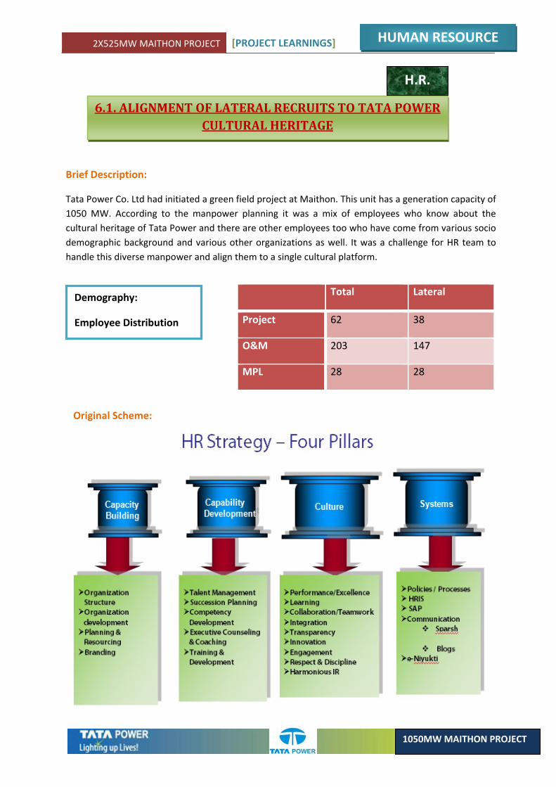
2X525MW MAITHON PROJECT [PROJECT LEARNINGS]
HUMAN RESOURCE
1050MW MAITHON PROJECT
Total Lateral
Project 62 38
O&M 203 147
MPL 28 28
6.1. ALIGNMENT OF LATERAL RECRUITS TO TATA POWER CULTURAL HERITAGE
H.R.
Brief Description:
Tata Power Co. Ltd had initiated a green field project at Maithon. This unit has a generation capacity of 1050 MW. According to the manpower planning it was a mix of employees who know about the cultural heritage of Tata Power and there are other employees too who have come from various socio demographic background and various other organizations as well. It was a challenge for HR team to handle this diverse manpower and align them to a single cultural platform.
Demography:
Employee Distribution
Original Scheme:
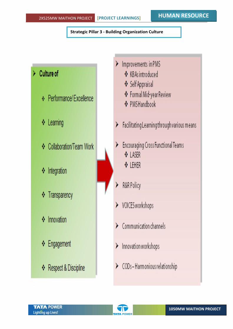
2X525MW MAITHON PROJECT [PROJECT LEARNINGS]
HUMAN RESOURCE
1050MW MAITHON PROJECT
Strategic Pillar 3 ‐ Building Organization Culture
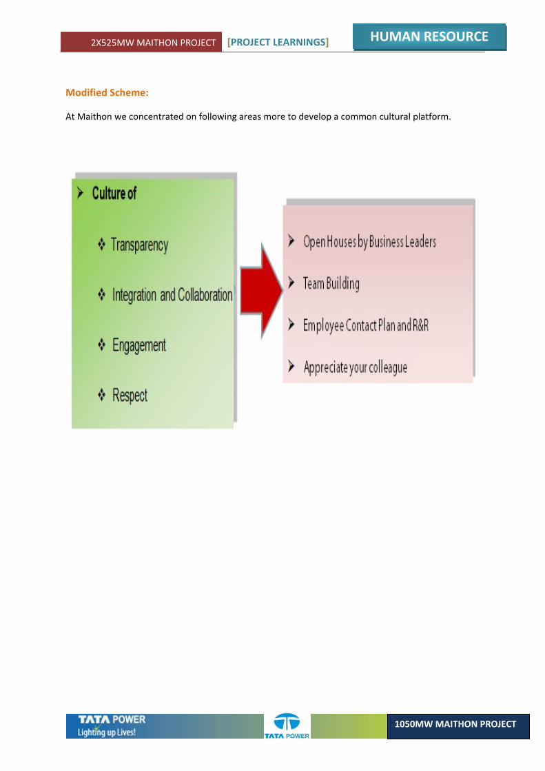
2X525MW MAITHON PROJECT [PROJECT LEARNINGS]
HUMAN RESOURCE
1050MW MAITHON PROJECT
Modified Scheme:
At Maithon we concentrated on following areas more to develop a common cultural platform.
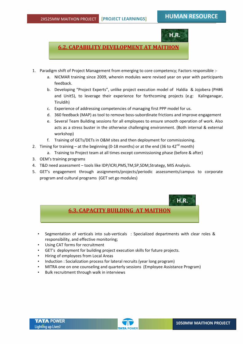
2X525MW MAITHON PROJECT [PROJECT LEARNINGS]
HUMAN RESOURCE
1050MW MAITHON PROJECT
6.2. CAPABILITY DEVELOPMENT AT MAITHON
H.R.
1. Paradigm shift of Project Management from emerging to core competency; Factors responsible :‐ a. NICMAR training since 2009, wherein modules were revised year on year with participants
feedback. b. Developing “Project Experts”, unlike project execution model of Haldia & Jojobera (PH#6
and Unit5), to leverage their experience for forthcoming projects (e.g: Kalinganagar, Tiruldih)
c. Experience of addressing competencies of managing first PPP model for us. d. 360 feedback (MAP) as tool to remove boss‐subordinate frictions and improve engagement e. Several Team Building sessions for all employees to ensure smooth operation of work. Also
acts as a stress buster in the otherwise challenging environment. (Both internal & external workshop)
f. Training of GETs/DETs in O&M sites and then deployment for commissioning. 2. Timing for training – at the beginning (0‐18 months) or at the end (36 to 42nd month)
a. Training to Project team at all times except commissioning phase (before & after) 3. OEM’s training programs 4. T&D need assessment – tools like IDP/ICRI,PMS,TM,SP,SDM,Strategy, MIS Analysis. 5. GET’s engagement through assignments/projects/periodic assessments/campus to corporate
program and cultural programs (GET set go modules)
6.3. CAPACITY BUILDING AT MAITHON
H.R.
• Segmentation of verticals into sub‐verticals : Specialized departments with clear roles & responsibility, and effective monitoring;
• Using CAT forms for recruitment • GET’s deployment for building project execution skills for future projects. • Hiring of employees from Local Areas • Induction : Socialization process for lateral recruits (year long program) • MITRA one on one counseling and quarterly sessions (Employee Assistance Program) • Bulk recruitment through walk in interviews
ACKNOWLEDGEMENT
This summarization of all the Learning at Maithon Site was made possible by wholehearted support of many members of the team. This compilation of Great Works & Achievements of Team Maithon was steered under meticulous guidance of the Team Leadership. In this regards Special Salutation goes to: Mr. Sanjay S. Bhattacharya, Mr. V.V.Namjoshi , Mr. R.T.Chaudhury & Mr. Sumit S. Ghosh .
The List is Long But Special mention is reserved for following members :
1. Manoj Samaiar .
2. Rohit Kakkar
3. O. P. Shridharan .
4. S. V. Reddy .
5. Mithun Majumdar .
6. Sarwottam Prasad .
7. Vivek Belkhade .
8. Vikas Roy .
9. Bhakti Raj .
10 . Basudev Mazumdar .
11. Balaji Sethuraman .
12. Ramesh Ojha .
13 . Shyam Sundar Choudhury .
14. Debnath Dibakar .
15. Pradip Kundu .
16. Sanjiv Kumar .
17. Debasis Barik .
18. Gopabandhu Satpathy
19. Ananjan Mukerjee
20. Alok Prasad
21. Mitish Karkera
SALUTATION TO “ PROJECT WARRIORS “
The Team name itself may ring a bell of nostalgia for all at Maithon Site. Any Great Accomplishment & Achievement requires the herculean efforts of many Great Leaders & Masses. Tata Powers' Maithon Green Field Project also had such innumerable contribution of Not only Company's Own employees but also those of other Stake holders like Vendors & Their Sub Contractors.
The exhaustive list is long enough to demand the writing of another book but here Special Thanks is reserved for a few . Nevertheless the names not mentioned also Reserves Special Thanks from the Team Maithon . The names of few individuals are as mentioned below:
1. Mr. Sanjay Agarwal – Head – NERP. 2. Mr. Jayanta Pal.3. Mr. Ranabir Chakraborty.4. Mr. S. Saha.5. Mr. Sabyasachi Sengupta .6. Mr. Amit Bhardwaj .7. Mr. Hansen D Souza.8. Mr. Premal Lodaria.9. Mr. Mahesh Agarwal.10. Mr. Kajal Singh.11. Mr. Niranjan Sahu. 12. Mr. Uttam Ojha.13. Mr. Sudip Dash 14. Mr. Suranjit Mishra.15. Mr. Praveen Chorghade .16. Mr. Sushil Choudhury – PM – Simplex.17. Mr. L. P. Nayak – Simplex.18. Mr. Abhijit – Simplex.19. Mr. R. Sethuraman – L&T – PES.20. Mr. Rana Dutta – L&T – PES.21. Mr. Banerjee – L&T – PES.22. Mr. Anirban Mukherjee – L&T – PES.23. Mr. Arnab Bhattacharya – L&T – PES.24. Mr. R.N. Roy – BHEL.25. Mr. Raychaudhury – BHEL.26. Mr. Sarkar – BHEL.27. Mr. S.S.Singh – BHEL – Techno.28. Mr. Srivastava – BHEL – Techno. 29. Mr. Acharya – BHEL – Techno.30. Mr. Manab Ghosh – BHEL – Techno.31. Mr. Sarvanand – BHEL – L&T.32. Mr. Pijush Bose – L&T – IDCT.33. Mr. Saha – BHEL – L&T.34. Mr. Biplab Chatterjee.35. Mr. Nitya Mandal.36. Mr. HImadri Bhatta.37. Mr. Amit Pal.
Related Documents


![The Manchu (Ch’ing [Qing]) Dynasty (compiled/edited by Prof. Fred Cheung) [Main sources:](https://static.cupdf.com/doc/110x72/56815e32550346895dcc9359/the-manchu-ching-qing-dynasty-compilededited-by-prof-fred-cheung-56bf1b57daef1.jpg)
