ITS Partner O.B.S S.L · Av. Cerdanyola 79-81 Local C 08172 Sant Cugat del Vallés · Barcelona (Spain) Phone: +34935839543 · [email protected] · www.ek.plus USER MANUAL EDFA812 310023 8 VAY OPTICAL AMPLIFIER V02

Welcome message from author
This document is posted to help you gain knowledge. Please leave a comment to let me know what you think about it! Share it to your friends and learn new things together.
Transcript

ITS Partner O.B.S S.L · Av. Cerdanyola 79-81 Local C 08172 Sant Cugat del Vallés · Barcelona (Spain)
Phone: +34935839543 · [email protected] · www.ek.plus
USER MANUAL
EDFA812 310023
8 VAY OPTICAL AMPLIFIER
V02

ITS Partner O.B.S S.L · Av. Cerdanyola 79-81 Local C 08172 Sant Cugat del Vallés · Barcelona (Spain)
Phone: +34935839543 · [email protected] · www.ek.plus
USER MANUAL EDFA 812
INDEX SAFETY INSTRUCTIONS: ................................................................................................................................................................................................ 4
INTRODUCTION: ..................................................................................................................................................................................................................... 5
Description: ............................................................................................................................................................................................................................ 5
Specifications: ...................................................................................................................................................................................................................... 6
Block Diagram: .................................................................................................................................................................................................................... 8
FRONT AND REAR PANEL: ........................................................................................................................................................................................... 9
INSTALLATION: ..................................................................................................................................................................................................................... 10
Unpacking:............................................................................................................................................................................................................................ 10
Operating Environment: ............................................................................................................................................................................................ 10
EDFA Mounting and Power Connection:.................................................................................................................................................... 10
Optical Connections: ..................................................................................................................................................................................................... 11
EDFA Connections: ........................................................................................................................................................................................................ 11
TOUCHSCREEN GUI SETTING:................................................................................................................................................................................ 12
4.1 Verification .................................................................................................................................................................................................................... 12
4.1.1 Initial Interface: ....................................................................................................................................................................................................... 12
4.1.2 Status Verification ............................................................................................................................................................................................... 13
4.1.3 Warning Signs: ....................................................................................................................................................................................................... 14
4.2 Setup Menu ................................................................................................................................................................................................................. 14
4.2.1 Enter PIN:.................................................................................................................................................................................................................... 15
4.2.2 APC Mode (Recommended): ...................................................................................................................................................................... 16
4.2.3 ACC Mode: ............................................................................................................................................................................................................... 17
4.2.4 AGC Mode: ............................................................................................................................................................................................................... 17
4.3 Network Configuration ...................................................................................................................................................................................... 18
4.3.1 DHCP ON/OFF: .................................................................................................................................................................................................... 18
4.3.2 IP Address: ................................................................................................................................................................................................................ 18
4.3.3 Subnet Mask: .......................................................................................................................................................................................................... 19
4.3.4 Default Gateway: ................................................................................................................................................................................................ 19
4.4 About ............................................................................................................................................................................................................................... 20
Web GUI Setting .................................................................................................................................................................................................................. 20

ITS Partner O.B.S S.L · Av. Cerdanyola 79-81 Local C 08172 Sant Cugat del Vallés · Barcelona (Spain)
Phone: +34935839543 · [email protected] · www.ek.plus
USER MANUAL EDFA 812
5.1 Accessing the Web interface ...................................................................................................................................................................... 20
5.2 Management .............................................................................................................................................................................................................. 21
5.2.1 Amplifier Status .................................................................................................................................................................................................... 21
5.2.2 Optical Switch (Option) .................................................................................................................................................................................. 22
5.2.3 Amplifier Setup ....................................................................................................................................................................................................23
5.2.4 Information: ............................................................................................................................................................................................................. 25
5.2.5 Thresholds: ............................................................................................................................................................................................................. 26
5.3 Network ......................................................................................................................................................................................................................... 28
5.3.1 IPv4 Address: ......................................................................................................................................................................................................... 28
5.3.2 SNMP: .......................................................................................................................................................................................................................... 28
5.3.3 Time Server: ........................................................................................................................................................................................................... 29
5.4 Security .......................................................................................................................................................................................................................... 29
5.4.1 Web Password: .................................................................................................................................................................................................... 29
5.4.2 Touch Screen: ...................................................................................................................................................................................................... 30
5.5 Service ............................................................................................................................................................................................................................. 31
5.5.1 Firmware Update ................................................................................................................................................................................................ 31
6.SNMP Management ......................................................................................................................................................................................................32

ITS Partner O.B.S S.L · Av. Cerdanyola 79-81 Local C 08172 Sant Cugat del Vallés · Barcelona (Spain)
Phone: +34935839543 · [email protected] · www.ek.plus
4
USER MANUAL EDFA 812
SAFETY INSTRUCTIONS:
WARNING:
EDFA812 high power EDFA, electric power supplied, is a generator of invisible laser radiation in the infrared and optical range, which can be dangerous for the eye and causes burn of the direct irradiation. Operation of the device requires that the personnel must completely understand and meets the required conditions of all laser safety & electrical safety.
Electrical Safety
EDFA812 operates from AC power source that supplies 90~132VAC / 176~264VAC or DC power source that supplies 36 to 72 VDC.
CAUTION:
EDFA812 must be well grounded in accordance with local and national electrical standards. Before supplying the power to the device, make sure the correct voltage is used. Failure to use the correct voltage could cause damage to the device.
Allow only personnel trained in electrical safety to operate this amplifier. Otherwise, injuries to personnel may occur.
Laser Safety
EDFA812 high power EDFA is class 4 laser safety according to the international classification that can burn the skin or cause devastating and permanent eye damage as a result of direct, diffuse or indirect beam viewing. These lasers may ignite combustible materials, and thus may represent a fire risk. These hazards may also apply to indirect or non-specular reflections of the beam, even from apparently matte surfaces-meaning that great care must be taken to control the beam path.
CAUTION:
Use appropriate laser safety eye-wear when operating this device.
DO not install or terminate fibers when amplifier is active.
DO not look directly at any fiber end. Always keep your eyes at least 30 cm away from any light-guiding fiber or device.
DO not view an activated fiber with optical instruments (e.g., magnifiers, microscopes)
DO not open the cover! Laser hazard might increase.
Keep in mind that merging multiple light signals will increase the hazard.
Allow only personnel trained in laser safety to operate this amplifier. Otherwise, injuries to personnel may occur.
ITS Partner O.B.S S.L · Av. Cerdanyola 79-81 Local C 08172 Sant Cugat del Vallés · Barcelona (Spain)
Phone: +34935839543 · [email protected] · www.ek.plus
5
USER MANUAL EDFA 812
INTRODUCTION: Description:
EDFA812 high power EDFA is characterized by low noise and high linearity performance to meet the most demanding requirements of CATV and FTTx applications. It offers a flexible, low-cost solution for large area distribution networks.
Touch Screen LCD
EDFA812 high power EDFA is the First Unit to embed touchscreen LCD in CATV industry.
Output Optical Power
EDFA812 high power EDFA has standard series that is based on the optical power included 25~40dBm before splitter.
It is available to make special modifications to a specified output power up to 43dBm before splitter.
This optical amplifier has built-in optical power splitter for providing up to 128 output ports. Standard is at 1, 2, 4, 8, 16, 32 or 64 output power port.
Control Modes
EDFA812 can be configured in one of three optical output power control modes:
• APC (Automatic Power Control): Output Optical Power Level Stabilization
• ACC (Automatic Current Control): Pump Current Level Stabilization
• AGC (Automatic Gain Control): Optical Gain Level Stabilization
Measurement
EDFA812 is equipped with standard measures of input and back reflection optical power and reflected power meter within 60 dB dynamic range. Measurement of reverse reflection is useful function to monitor networks and to configure optimal settings exploitation.
Optical Switch (Optional)
EDFA812 can be equipped with automatic redundant input port according to customer request.
Optical power level at each of the two input ports is measured independently, allowing you to instantly switch from the primary input port to the backup input port when the power on signal.
WDM PON (Optional)
EDFA812 can be equipped with PON port according to customer request for xPON networks.
Management
All EDFA812 series optical amplifiers have a built-in Web server, which can be reviewed by any of the widely used web browser. Controlling and monitoring of the amplifier is used by the menu of interactive Web pages.
On-demand monitoring of the amplifier can also be accessed by our SNMP Manager.
Mechanical
All 2000 series amplifiers are in a standard 2U (1U and 3U), 19 ", equipped with 3 reliable cooling fans operating in parallel with microprocessor overheating protection. The Amplifier can work with temperature up to 50°c, and, if necessary, up to 60°c is optional. Standard power operates on AC 90~132V or 176~264V with high efficiency and high reliability.

ITS Partner O.B.S S.L · Av. Cerdanyola 79-81 Local C 08172 Sant Cugat del Vallés · Barcelona (Spain)
Phone: +34935839543 · [email protected] · www.ek.plus
6
USER MANUAL EDFA 812
Specifications:
Optical Characteristics
Parameter Unit Value
Optical Input Wavelength nm 1545 ~ 1565
Optical Input Power dBm -10~+10
Output Optical Power dBm See Ordering Information
Typical Output Power per port dBm ≥ 12
Output Power Stabilization Range % 30 ~100
Port Numbers -- See Ordering Information
Output Power Tolerance dB ± 0.5
Port Uniformity dB ± 0.6
Noise Figure dB ≤ 5.5
Optical Test Port dB -5~+5
Return Loss Input/Output dB ≥ 45
Isolation Output ► Input dB ≥ 40
Polarization Dependence dB ≤ 0.3
1. Noise figure at 0 dBm input power, nominal output power and signal wavelength 1550 nm.
PON Characteristics (Optional)
Parameter Unit Value
PON Wavelengths nm 1260~1360 & 1480~1500
Insertion Loss dB ≤ 1
Isolation CATV ► PON dB 50 @ 1545~1565 nm
Isolation COM ► PON dB 15 @ 1545~1565 nm
Return Loss dB ≥ 50
Optical Switch for 2 Inputs (Optional)
Parameter Unit Value
Insertion Loss dB < 1
Crosstalk dB ≤ -55
Repeatability dB ± 0.05
Switch Time ms ≤ 10
Return Loss dB ≥ 50

ITS Partner O.B.S S.L · Av. Cerdanyola 79-81 Local C 08172 Sant Cugat del Vallés · Barcelona (Spain)
Phone: +34935839543 · [email protected] · www.ek.plus
7
USER MANUAL EDFA 812
General Characteristics
Parameter Unit Value
Power Supply pcs 2 (1 default, 1 optional)
Chassis Type -- 1U, 2U, 3U 19’’ Rack mounted
AC Input Voltage Vac 90~132 or 176~264
DC Input Voltage Vdc 36~ 72
Power Consumption W ≤75
Dimension (W x H x D) mm 484*44*385 (1U)
mm 484*88*336 or 484*88*416 (2U)
Operating Temperature Range °C -5~+50
Management Interface
Parameter Value
Data Link Layer Ethernet 10/100 Base-T (and LLDP optional)
Network Layer IPv4, ICMP
Transport Layer UDP, TCP
Application Layer SNMPv1/v2c, DHCP, Web
Connectors 10/100 Base-T
Front Panel Management 3.5” 480 x 320 Color Touch Screen LCD for 2U and 3U 2.4” 320 x 240 Color Touch Screen LCD for 1U
Control Mode
Parameter Value
Stabilization Mode
Pump Current
Output Optical Power
Optical Gain
Automatic Pump Shutdown Mode
Low Input Power (LOS)
High Back Reflection
Overheating

ITS Partner O.B.S S.L · Av. Cerdanyola 79-81 Local C 08172 Sant Cugat del Vallés · Barcelona (Spain)
Phone: +34935839543 · [email protected] · www.ek.plus
8
USER MANUAL EDFA 812
Block Diagram:
2 Inputs Optical Switch (Optional)
Standard WDM PON (Optional)

ITS Partner O.B.S S.L · Av. Cerdanyola 79-81 Local C 08172 Sant Cugat del Vallés · Barcelona (Spain)
Phone: +34935839543 · [email protected] · www.ek.plus
9
USER MANUAL EDFA 812
FRONT AND REAR PANEL: (2U, CATV, SC/APC)
1 6 7 8
2 3 4 5
9 10 11 12 13 14
9 10 11 12 13 14
(1U, CATV, SC/APC, Optical Switch)
3 4 1 5 6 7 8
2 9 10 11 12 13 14
Version I : The total output power < 38dBm
Version II : The total output power ≥ 38dBm

ITS Partner O.B.S S.L · Av. Cerdanyola 79-81 Local C 08172 Sant Cugat del Vallés · Barcelona (Spain)
Phone: +34935839543 · [email protected] · www.ek.plus
10
USER MANUAL EDFA 812
No. Description No. Description
1 3.2’’/2.4” Color Touchscreen LCD 8 Handle
2 RJ45 LAN Port for Management 9 Removable Fan
3 LCD Reset1 10 Hot Plug-gable Power 1:AC Input
4 System Reset2 11 Hot Plug-gable Power 2: DC Input
5 Optical Testing Port 12 Grounding Screw
6 Optical Input Port 13 Removable Fan
7 Optical Output Ports (PON Ports) 14 Removable Fan
INSTALLATION: EDFA812 high power EDFA kit includes:
Item Quantity Item Quantity
EDFA Unit 1 Power Cable 1 or 2
User’s Manual 1 Testing Report 1
Quick Guide 1 Packing Box 1
Unpacking:
WARNING:
To avoid electrical shock, do not operate the unit if it bears any sign of damage to any portion of its exterior surface, such as the outer cover or panels. Wear an anti-static wrist strap and work in an electrostatic discharge (ESD) controlled area.
1) Inspect the shipping box for any for any obvious damage.
2) Unpack the unit from all packaging boxes.
3) Inspect the appearance of the unit for any shipping damage.
4) Read the user’s manual thoroughly and become familiar with all safety symbols and instructions to ensure that the unit is operated and maintained safely.
5) Document and inform the shipping company, if any damage is found.
6) Keep the shipping boxes and their inserts for future shipment in case the product needs repair.
NOTE: In the event of a reshipment back to the manufacturer, any additional damage caused by not using the original boxes will be considered the responsibility of the customer.
Operating Environment:
EDFA812 operates at:
Temperature: 0°C to +50°C (Recommended)
Humidity: 95% maximum (non-condensing conditions)
It is recommend operating in a dust-free environment
EDFA Mounting and Power Connection:
1) Place the unit into a 19-inch wide rack or cabinet.

ITS Partner O.B.S S.L · Av. Cerdanyola 79-81 Local C 08172 Sant Cugat del Vallés · Barcelona (Spain)
Phone: +34935839543 · [email protected] · www.ek.plus
11
USER MANUAL EDFA 812
2) Plug the power cord supplied on the rear panel and place the other end of power source, please note the specification of power supply units.
Power Supply Connection Description
AC input: 90~132VAC,50/60 Hz or 176~264VAC, 50/60 Hz
DC input: 32~72VDC for DC 48V
3) Make sure grounding well
Optical Connections:
CAUTION:
ALWAYS MAKE SURE that all power is removed from EDFA812 before optical connectors are connected
Cleaning for Fiber Patch Cord Connectors
− Remove the fiber connector dust cap and wipe the fiber connector tip with high-quality fiber cleaner or a dry lint-free cloth. Check if there are scratches or debris on connector surface by using a fiber scope.
− If no scratches or debris are found that means the connector is now clean and ready for connection.
− If debris or scratches are found, then repeat the fiber patch cord connector cleaning.
Cleaning for Fiber Optic Adapter
− Compressed air may be used to clean fiber optic adapter. Use compressed air with at least the following specifications:
− Non-residue, inert gas for precision dust removal
− Ultra-filtered to < 0.2 microns
− Recommended for optical systems
− Using compressed air as listed above, remove the adapter dust cover and hold the can of compressed air about 6 inches from the connector. After spraying a few short bursts into the adapter, the connector is clean and ready for connection.
− If compressed air is not available, the fiber adapter connector can be cleaned by 2.5 mm cotton swap or connector plate may be removed to clean the internal fiber patch cords.
NOTE: Use caution when handling fibers. Do not exceed fiber manufacturers pulling tension or bend radius specifications when removing fiber bulkhead connector plate.
EDFA Connections:
1) Clean all fiber patch cords before connecting.
2) Make sure the laser key switch on the front panel of the transmitter is in the OFF position.
3) Connect a fiber patch cord from the output of the transmitter to the optical power meter, turn key ON position of transmitter laser. Be sure the optical output is in the -10~+10dBm range (0dBm is recommended).
ITS Partner O.B.S S.L · Av. Cerdanyola 79-81 Local C 08172 Sant Cugat del Vallés · Barcelona (Spain)
Phone: +34935839543 · [email protected] · www.ek.plus
12
USER MANUAL EDFA 812
4) Turn switch key of transmitter to the OFF position and power OFF.
5) Connect the fiber patch cord to the amplifier input. Power up that transmitter once the fiber connections to the amplifier input are secure.
6) Turn the transmitter laser key switch to the ON position.
NOTE: When input power is out range of -10~ +10dBm, EDFA812 automatically turns off pump laser to protect itself and installation personnel.
CAUTION:
NEVER disconnect any fiber connections to the EDFA while it is powered.
TOUCHSCREEN GUI SETTING:
CAUTION:
1) To avoid damaging the touchscreen, do not tap it with anything sharp or apply excessive pressure to it with your fingertips.
2) It is recommended to use fingers when you use the touchscreen.
4.1 Verification
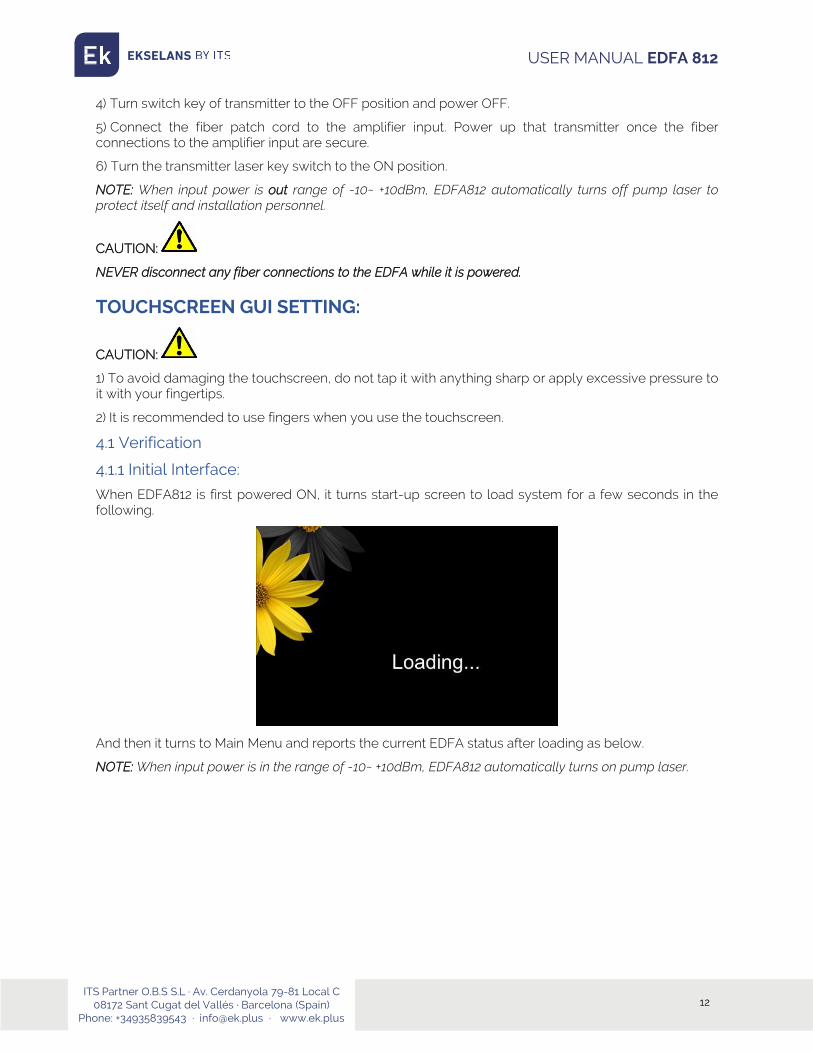
4.1.1 Initial Interface:
When EDFA812 is first powered ON, it turns start-up screen to load system for a few seconds in the following.
And then it turns to Main Menu and reports the current EDFA status after loading as below.
NOTE: When input power is in the range of -10~ +10dBm, EDFA812 automatically turns on pump laser.

ITS Partner O.B.S S.L · Av. Cerdanyola 79-81 Local C 08172 Sant Cugat del Vallés · Barcelona (Spain)
Phone: +34935839543 · [email protected] · www.ek.plus
13
USER MANUAL EDFA 812
4.1.2 Status Verification
EDFA812 has built-in power meter to get real value of input power displayed on the touchscreen with the accuracy that is not worse than ± 0.2 dB (-10dBm to +10dBm). Power output sensor calibrates the optical output power of EDFA812 automatically by MCU. Default factory settings of Amplifier mode is APC.
Set 16X19dBm for example as below: after power on, EDFA812 shows that Input Power is 0dBm, Current is around 80/80%, Port Output Power is 19dBm, Inner temperature is 30℃ which means EDFA812 working fine.
No. Description
1 Real-time display of details of “Setup”, ”Network Config” and “About”, please see 4.2, 4.3, 4.3
2 “Setup”, ”Network Config” and “About” which is vertically on the right side of the touchscreen, select any menu by finger tap, please see 4.2, 4.3, 4.4
3 Link Down: RJ45 Ethernet cable is disconnected between EDFA and Computer; Link Up: RJ45 Ethernet cable is well connected between EDFA and Computer
4 Warning signs, see details at 4.1.3
5 System up-time after Power ON
6 3 groups current display for power higher than 38dBm
① ②
③ ④ ⑤
⑥
ITS Partner O.B.S S.L · Av. Cerdanyola 79-81 Local C 08172 Sant Cugat del Vallés · Barcelona (Spain)
Phone: +34935839543 · [email protected] · www.ek.plus
14
USER MANUAL EDFA 812
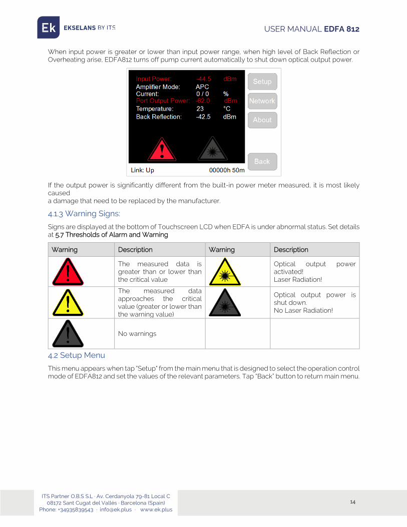
When input power is greater or lower than input power range, when high level of Back Reflection or Overheating arise, EDFA812 turns off pump current automatically to shut down optical output power.
If the output power is significantly different from the built-in power meter measured, it is most likely caused a damage that need to be replaced by the manufacturer.
4.1.3 Warning Signs:
Signs are displayed at the bottom of Touchscreen LCD when EDFA is under abnormal status. Set details at 5.7 Thresholds of Alarm and Warning
Warning Description Warning Description
The measured data is greater than or lower than the critical value
Optical output power activated! Laser Radiation!
The measured data approaches the critical value (greater or lower than the warning value)
Optical output power is shut down. No Laser Radiation!
No warnings
4.2 Setup Menu
This menu appears when tap "Setup" from the main menu that is designed to select the operation control mode of EDFA812 and set the values of the relevant parameters. Tap “Back” button to return main menu.

ITS Partner O.B.S S.L · Av. Cerdanyola 79-81 Local C 08172 Sant Cugat del Vallés · Barcelona (Spain)
Phone: +34935839543 · [email protected] · www.ek.plus
15
USER MANUAL EDFA 812
Four modes are (Sub-menu) displayed on touchscreen.
Control Mode Description User Level
APC (Automatic Power Control) Output Optical Power Level Stabilization Basic User (Recommended)
ACC (Automatic Current Control) Pump Current Level Stabilization Only Professional
AGC (Automatic Gain Control) Optical Gain Level Stabilization Only Professional
Turn off Pump Turn Off the Current of Pump Laser Basic User
Content of control mode is as below
Item Description Unit
Input Power The optical power of the input signal dBm
Amplifier Mode The operating control mode : APC,ACC,AGC
Current Pump laser current %
Port Output Power Optical output power of each output port dBm
Temperature Temperature inside of the device ℃
Back Reflection Back reflection optical power (back direction) dBm
4.2.1 Enter PIN:
The first time to enter APC, ACC or AGC mode after EDFA power up, it shows “Enter PIN” interface in order to avoid false touch and prevent unauthorized users. Input PIN code to save and run.
The default PIN code is “1111”, go web management interface to change PIN code.
The default PIN authorization timeout is “5” minutes (User doesn’t touch screen over 5 minutes), go web management interface to change PIN authorization timeout.

ITS Partner O.B.S S.L · Av. Cerdanyola 79-81 Local C 08172 Sant Cugat del Vallés · Barcelona (Spain)
Phone: +34935839543 · [email protected] · www.ek.plus
16
USER MANUAL EDFA 812
Keyboard Explanation
Button Description Button Description
Tap to return to the previous screen menu without saving
Clear up one number
Allows to clear all input field
Saves specified parameter/ value/ mode to apply
4.2.2 APC Mode (Recommended):
Tap “APC” button to enter APC mode. APC mode is system default control mode. APC (Automatic Power Control) is established and maintained by the output power regardless of the changes of the input signal and temperature. EDFA812 automatically adjusts the current laser diode pumping to ensure stabilization of the desired output power that measured by an internal sensor.
Output power value is appeared at the top of menu as shows its value. Set the desired value by using the touch keyboard to input and then to save, the LCD display as below:
Note1: The desired value of output power cannot higher than the value of EDFA maximum Output power, otherwise, this desired value will not be activated.
Note2: The way to turn output power to “0” at APC mode is to input “0” and save it.

ITS Partner O.B.S S.L · Av. Cerdanyola 79-81 Local C 08172 Sant Cugat del Vallés · Barcelona (Spain)
Phone: +34935839543 · [email protected] · www.ek.plus
17
USER MANUAL EDFA 812
4.2.3 ACC Mode:
Tap “ACC” button to enter ACC mode
ACC mode (Automatic Current Control) provides the direct power, control the device through the management of current laser diode pumping. Current is set as a percentage of the maximum value. The maximum current is set by the manufacturer. Default Value of ACC mode is 80/80% (Recommended).
Current is appeared at the top of menu as shows its value.set the desired value using the touch keyboard to input value
4.2.4 AGC Mode:
Tap “AGC” button to enter AGC mode
AGC mode (Automatic Gain Control) is established and maintained by the fixed value of the input signal gain regardless of the input signal and temperature. The device automatically adjusts the current laser diode-pumped high-power cascade to maintain required gain, which is based on measurement of internal sensor.
Gain is appeared at the top of menu as shows its value. Set the desired value using the touch keyboard to input value.
Note: When input power is 0dBm, the output gain value is same as Port Output Power on touchscreen.
CAUTION:
NEVER disconnect any fiber connections to the EDFA while it is powered.
ITS Partner O.B.S S.L · Av. Cerdanyola 79-81 Local C 08172 Sant Cugat del Vallés · Barcelona (Spain)
Phone: +34935839543 · [email protected] · www.ek.plus
18
USER MANUAL EDFA 812
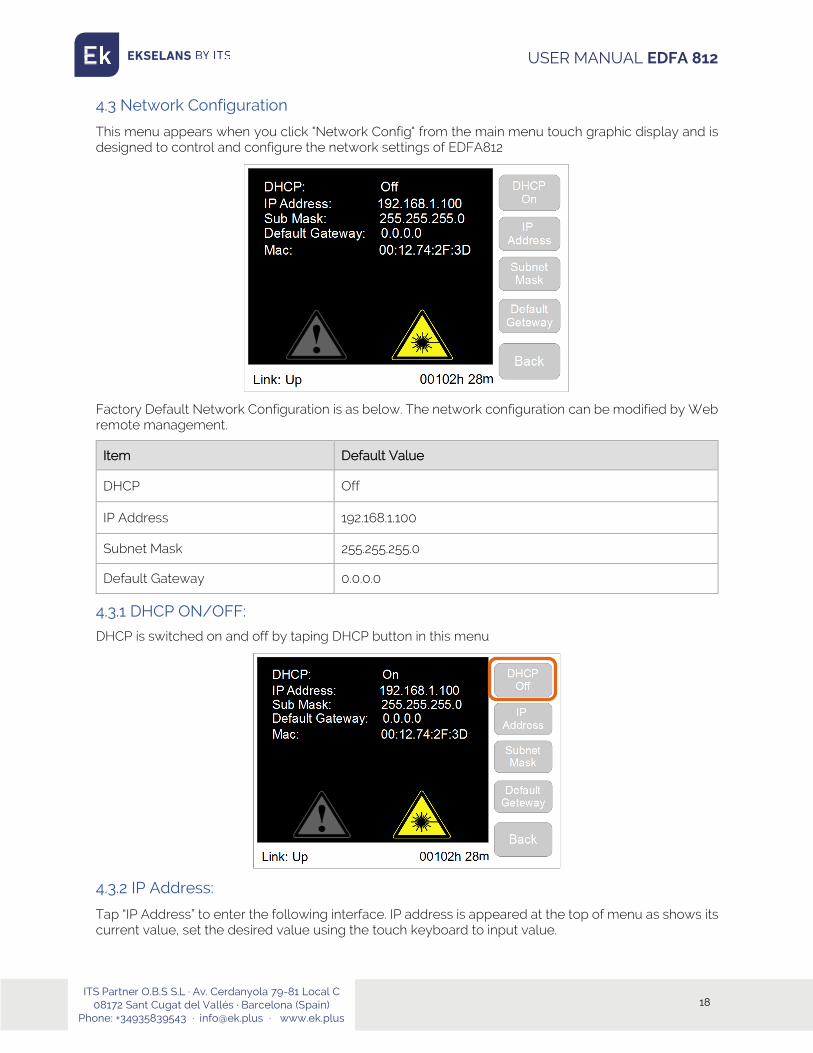
4.3 Network Configuration
This menu appears when you click "Network Config" from the main menu touch graphic display and is designed to control and configure the network settings of EDFA812
Factory Default Network Configuration is as below. The network configuration can be modified by Web remote management.
Item Default Value
DHCP Off
IP Address 192.168.1.100
Subnet Mask 255.255.255.0
Default Gateway 0.0.0.0
4.3.1 DHCP ON/OFF:
DHCP is switched on and off by taping DHCP button in this menu
4.3.2 IP Address:
Tap “IP Address” to enter the following interface. IP address is appeared at the top of menu as shows its current value, set the desired value using the touch keyboard to input value.

ITS Partner O.B.S S.L · Av. Cerdanyola 79-81 Local C 08172 Sant Cugat del Vallés · Barcelona (Spain)
Phone: +34935839543 · [email protected] · www.ek.plus
19
USER MANUAL EDFA 812
Note1: In accordance with the version of the Internet Protocol version 4 (IPv4), IP address has a length of 4 bytes. In this version of an IP address is a 32-bit signed number, it is convenient form of writing which is written as four decimal numbers from 0 to 255, separated by comma.
4.3.3 Subnet Mask:
Tap “Subnet Mask” to enter into the following interface. Subnet mask is appeared at the top of menu as shows its value, set the desired value using the touch keyboard
4.3.4 Default Gateway:
Set the default gateway address and define the network gateway to which to send traffic for which you cannot determine a route based on routing tables.
ITS Partner O.B.S S.L · Av. Cerdanyola 79-81 Local C 08172 Sant Cugat del Vallés · Barcelona (Spain)
Phone: +34935839543 · [email protected] · www.ek.plus
20
USER MANUAL EDFA 812
Default Gateway is appeared at the top of menu as shows its value, set the desired value using the touch keyboard to input value
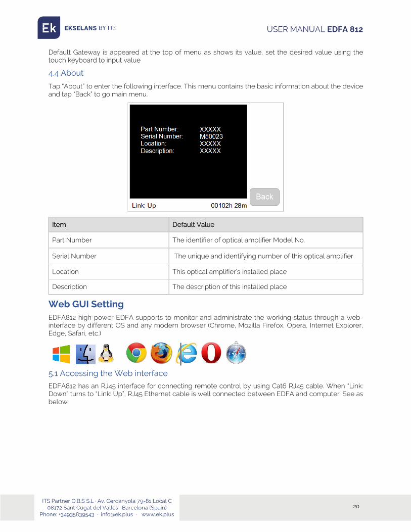
4.4 About
Tap “About” to enter the following interface. This menu contains the basic information about the device and tap “Back” to go main menu.
Item Default Value
Part Number The identifier of optical amplifier Model No.
Serial Number The unique and identifying number of this optical amplifier
Location This optical amplifier’s installed place
Description The description of this installed place
Web GUI Setting EDFA812 high power EDFA supports to monitor and administrate the working status through a web-interface by different OS and any modern browser (Chrome, Mozilla Firefox, Opera, Internet Explorer, Edge, Safari, etc.)
5.1 Accessing the Web interface
EDFA812 has an RJ45 interface for connecting remote control by using Cat6 RJ45 cable. When “Link: Down” turns to “Link: Up”, RJ45 Ethernet cable is well connected between EDFA and computer. See as below:

ITS Partner O.B.S S.L · Av. Cerdanyola 79-81 Local C 08172 Sant Cugat del Vallés · Barcelona (Spain)
Phone: +34935839543 · [email protected] · www.ek.plus
21
USER MANUAL EDFA 812
Make sure IP address of computer is 192.168.1.x (x=2~255). Input 192.168.1.1 into web browser to get following interface. Username and password are requested.
Note: the default username and password is as below:
Username Password Authorization
Admin PassAdmin Reading and setting parameters
Read readonly Reading parameters Only
5.2 Management 5.2.1 Amplifier Status
After input correct user name & password, and login, the general page of the web interface is appeared. This home page allows a quick system overview.

ITS Partner O.B.S S.L · Av. Cerdanyola 79-81 Local C 08172 Sant Cugat del Vallés · Barcelona (Spain)
Phone: +34935839543 · [email protected] · www.ek.plus
22
USER MANUAL EDFA 812
5.2.2 Optical Switch (Option)
Click “Optical Switch” to control optical switch panel.
This optional function is only available for the EDFA equipped with optical switch module inside.
Name Description
Input1 Force to Input1
Input2 Force to Input2
Auto_delta Input1 and Input2 have same priority
Auto_input1 Input1 is master, input2 is slave
Auto_input2 Input2 is master, input1 is slave
There are 5 modes of optical switch function for different networks and requirements
Auto_delta Block Diagram

ITS Partner O.B.S S.L · Av. Cerdanyola 79-81 Local C 08172 Sant Cugat del Vallés · Barcelona (Spain)
Phone: +34935839543 · [email protected] · www.ek.plus
23
USER MANUAL EDFA 812
User can set the value of delta input power switch for different demands.
Auto_input1/Auto_input2 Block Diagram
User can set the value of higher input power switch and the lower input power switch.
5.2.3 Amplifier Setup
Click ”Amplifier Setup” to control and change the operating control mode of the device by “Save” button.EDFA812 also can be found in sections by Touchscreen LCD Setting.
There are 3 kinds of control modes of this amplifier are shown in the table below
Control Mode Description User Level
APC (Automatic Power Control) Output Optical Power Level Stabilization Basic User (Recommended)
ACC (Automatic Current Control) Pump Current Level Stabilization Only Professional
AGC (Automatic Gain Control) Optical Gain Level Stabilization Only Professional

ITS Partner O.B.S S.L · Av. Cerdanyola 79-81 Local C 08172 Sant Cugat del Vallés · Barcelona (Spain)
Phone: +34935839543 · [email protected] · www.ek.plus
24
USER MANUAL EDFA 812
Warning Alarm for Power Supply and Input Power
Name Description
Ignore PS 1 When EDFA is equipped 2pcs power supplies, if only one power supply is connected to power source powered or only one is working, the system gives yellow alarming sign to user. And user can force to turn off alarming sign Ignore PS 2
Ignore Input1 When EDFA is equipped 2inputs optical switch module,local network only deployed one input, user can force to turn off the other input to turn off alarm sign. Ignore Input2
APC mode (Recommended):
System default mode is APC mode that is easy to operate for basic user. Click “PortOutputPower” to set new output power value.
Please note: The new value is adjustable according to customer’s request.
For example, when customer ordered a 16x19 high power EDFA (16 ports with 19dBm per port).
The new value of output power is in 30%~100% range of 19dBm. However, It is not available when new value is higher than 19dBm.
ACC mode:
Click “ACC” to ACC mode to change Pump Current. Default pump current is 80% which is the best optimization for EDFA812.Click “PumpCurrent” to set new current value. The new value of pump current is from 0% to 80%. It is not available when new value is higher than 80%.

ITS Partner O.B.S S.L · Av. Cerdanyola 79-81 Local C 08172 Sant Cugat del Vallés · Barcelona (Spain)
Phone: +34935839543 · [email protected] · www.ek.plus
25
USER MANUAL EDFA 812
AGC mode:
Click “AGC” to AGC mode to change output gain value for each port.
Note: when disabled “PumpCurrentEnable”, all pump lasers are shut down immediately.
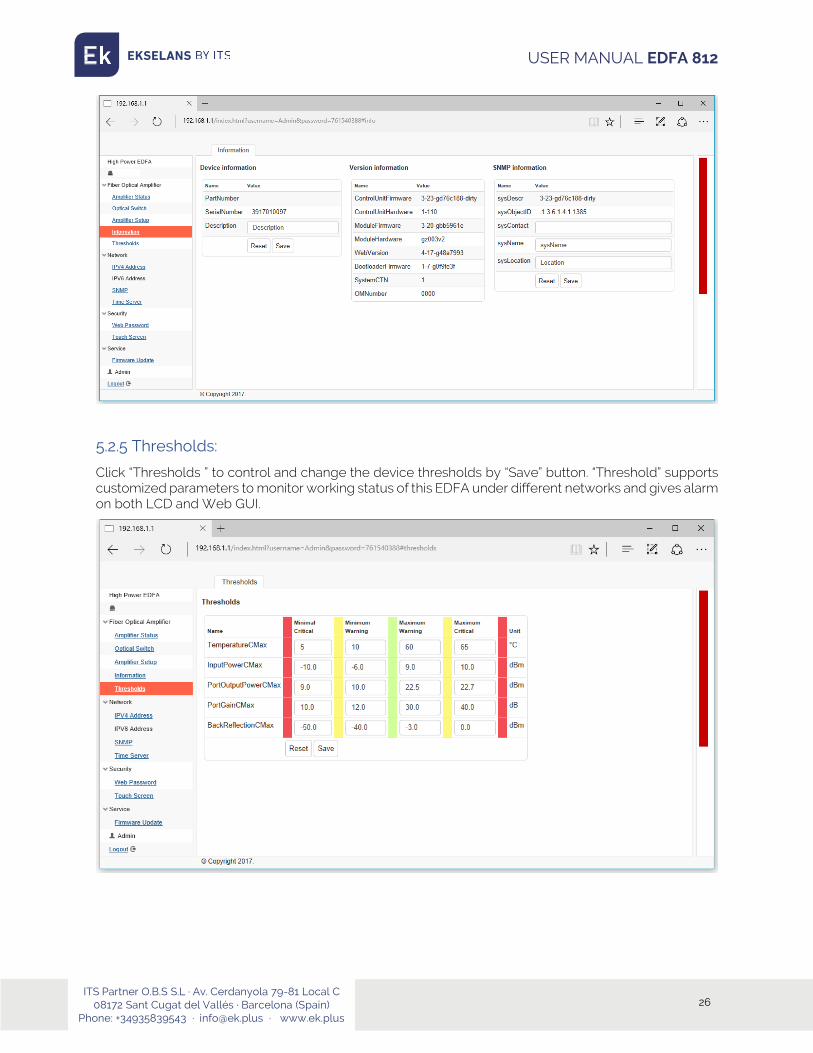
5.2.4 Information:
Click “Information” to see device information that indicates part number, serial number, system location, SNMP, hardware and firmware details.
ITS Partner O.B.S S.L · Av. Cerdanyola 79-81 Local C 08172 Sant Cugat del Vallés · Barcelona (Spain)
Phone: +34935839543 · [email protected] · www.ek.plus
26
USER MANUAL EDFA 812
5.2.5 Thresholds:
Click “Thresholds ” to control and change the device thresholds by “Save” button. “Threshold” supports customized parameters to monitor working status of this EDFA under different networks and gives alarm on both LCD and Web GUI.
ITS Partner O.B.S S.L · Av. Cerdanyola 79-81 Local C 08172 Sant Cugat del Vallés · Barcelona (Spain)
Phone: +34935839543 · [email protected] · www.ek.plus
27
USER MANUAL EDFA 812
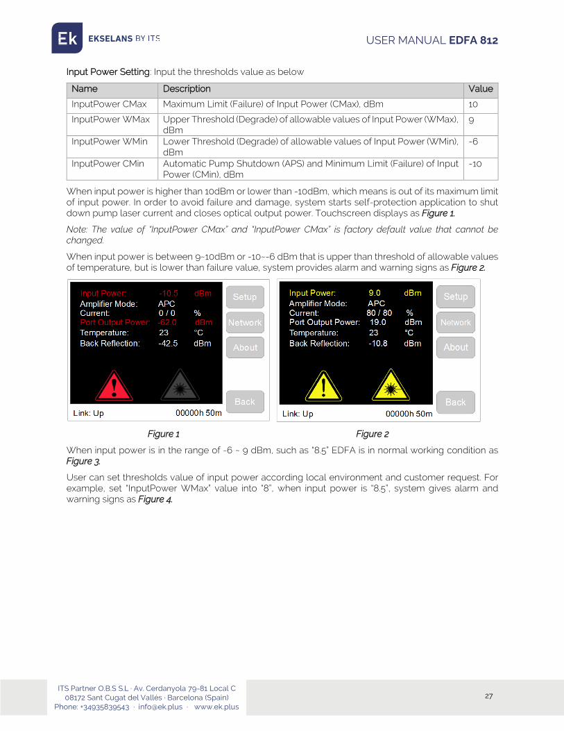
Input Power Setting: Input the thresholds value as below
Name Description Value
InputPower CMax Maximum Limit (Failure) of Input Power (CMax), dBm 10
InputPower WMax Upper Threshold (Degrade) of allowable values of Input Power (WMax), dBm
9
InputPower WMin Lower Threshold (Degrade) of allowable values of Input Power (WMin), dBm
-6
InputPower CMin Automatic Pump Shutdown (APS) and Minimum Limit (Failure) of Input Power (CMin), dBm
-10
When input power is higher than 10dBm or lower than -10dBm, which means is out of its maximum limit of input power. In order to avoid failure and damage, system starts self-protection application to shut down pump laser current and closes optical output power. Touchscreen displays as Figure 1.
Note: The value of “InputPower CMax” and “InputPower CMax” is factory default value that cannot be changed.
When input power is between 9~10dBm or -10~-6 dBm that is upper than threshold of allowable values of temperature, but is lower than failure value, system provides alarm and warning signs as Figure 2.
Figure 1 Figure 2
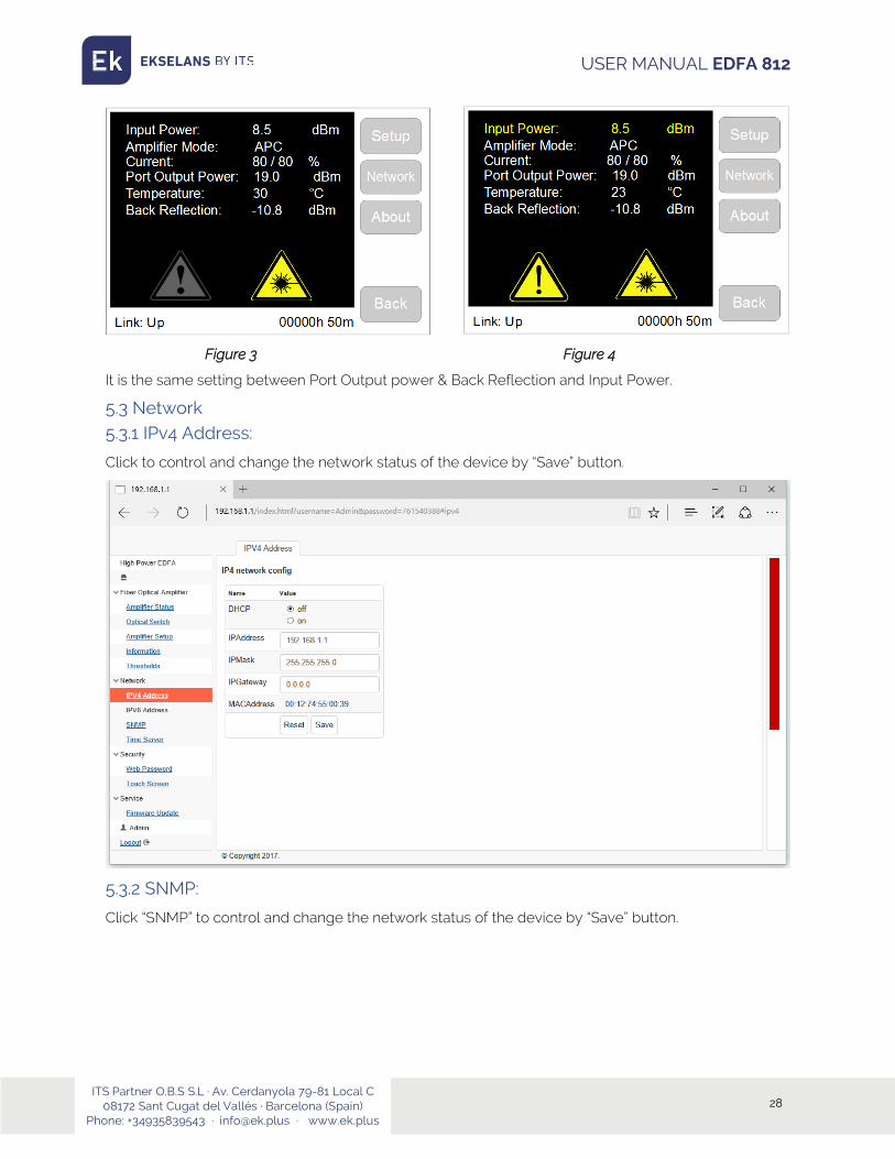
When input power is in the range of -6 ~ 9 dBm, such as “8.5” EDFA is in normal working condition as Figure 3.
User can set thresholds value of input power according local environment and customer request. For example, set “InputPower WMax” value into “8”, when input power is “8.5”, system gives alarm and warning signs as Figure 4.
ITS Partner O.B.S S.L · Av. Cerdanyola 79-81 Local C 08172 Sant Cugat del Vallés · Barcelona (Spain)
Phone: +34935839543 · [email protected] · www.ek.plus
28
USER MANUAL EDFA 812
Figure 3 Figure 4
It is the same setting between Port Output power & Back Reflection and Input Power.
5.3 Network 5.3.1 IPv4 Address:
Click to control and change the network status of the device by “Save” button.
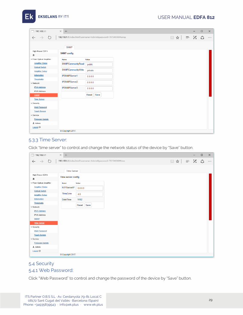
5.3.2 SNMP:
Click “SNMP” to control and change the network status of the device by “Save” button.
ITS Partner O.B.S S.L · Av. Cerdanyola 79-81 Local C 08172 Sant Cugat del Vallés · Barcelona (Spain)
Phone: +34935839543 · [email protected] · www.ek.plus
29
USER MANUAL EDFA 812
5.3.3 Time Server:
Click “time server” to control and change the network status of the device by “Save” button.
5.4 Security 5.4.1 Web Password:
Click “Web Password” to control and change the password of the device by “Save” button.

ITS Partner O.B.S S.L · Av. Cerdanyola 79-81 Local C 08172 Sant Cugat del Vallés · Barcelona (Spain)
Phone: +34935839543 · [email protected] · www.ek.plus
30
USER MANUAL EDFA 812
5.4.2 Touch Screen:
Click “Touch Screen” to change LCD display Backlight parameters and PIN code for touch LCD screen of the device by “Save” button.
PIN Code Setting: Input new PIN code and click “apply”, then Power OFF of EDFA812 and Power ON, new PIN code is activated.

ITS Partner O.B.S S.L · Av. Cerdanyola 79-81 Local C 08172 Sant Cugat del Vallés · Barcelona (Spain)
Phone: +34935839543 · [email protected] · www.ek.plus
31
USER MANUAL EDFA 812
5.5 Service 5.5.1 Firmware Update
Click “firmware update” to upgrade device by “Start Bootloader” button.
Web browser goes to the interface as below, click “Browse” to find firmware and then click button “Upload Firmware”. After finished uploading, click “Go Application” button and then restart the device.

ITS Partner O.B.S S.L · Av. Cerdanyola 79-81 Local C 08172 Sant Cugat del Vallés · Barcelona (Spain)
Phone: +34935839543 · [email protected] · www.ek.plus
32
USER MANUAL EDFA 812
After upload firmware and restart, EDFA touchscreen LCD goes to calibration mode.
LCD Calibration Mode: Use a pen to point touch screen and follows its steps. Touch the center point of cross according to LCD displayed.
After calibrated, LCD display goes to in the Initial interface, tap “Setup”, LCD display restart and run to working status.
6.SNMP Management EDFA812 offers MIB document for different network requirement. Download a MIB browser to configure network information.

ITS Partner O.B.S S.L · Av. Cerdanyola 79-81 Local C 08172 Sant Cugat del Vallés · Barcelona (Spain)
Phone: +34935839543 · [email protected] · www.ek.plus
33
USER MANUAL EDFA 812

ITS Partner O.B.S S.L · Av. Cerdanyola 79-81 Local C 08172 Sant Cugat del Vallés · Barcelona (Spain)
Phone: +34935839543 · [email protected] · www.ek.plus
34
USER MANUAL EDFA 812
Related Documents