ED A/C Air Conditioning System 1 Chonan T echnical Service Training Center

Welcome message from author
This document is posted to help you gain knowledge. Please leave a comment to let me know what you think about it! Share it to your friends and learn new things together.
Transcript

8/9/2019 ED_AIRCON
http://slidepdf.com/reader/full/edaircon 1/17
ED A/C
Air Conditioning System
1 Chonan Technical Service Training Center

8/9/2019 ED_AIRCON
http://slidepdf.com/reader/full/edaircon 2/17
ED A/C
Chonan Technical Service Training Center 2

8/9/2019 ED_AIRCON
http://slidepdf.com/reader/full/edaircon 3/17
ED A/C
Objectives
To understand the components of air conditioning system.
To understand the control function and operation condition.
To understand the troubleshooting method.
The A/C-Heater system combines heating, cooling, ventilation, dehumidifying. The heating system can be made
simply as is utilized the heat generated by the engine. In the other hand the cooling system requires more
complicated equipment to create cool air. When air is cooled, the moisture in the air condenses and forms water
droplets that separate from the air. The airflow is controlled by manual type and automatic type.
Full Automatic Temperature Control (FATC) features completely automatic control of discharge air temperature.
FATC also controls the circulation and humidity of the air inside the vehicle.
With FATC, the driver selects the temperature and the FATC functions to maintain that temperature, regardless
of outside temperature changes. A FATC control module controls air conditioning, ventilating, heating, and
defrosting systems. These electronic control systems automatically adjust doors, blower speeds, and
compressor cycling.
3 Chonan Technical Service Training Center

8/9/2019 ED_AIRCON
http://slidepdf.com/reader/full/edaircon 4/17
ED A/C
Chonan Technical Service Training Center 4

8/9/2019 ED_AIRCON
http://slidepdf.com/reader/full/edaircon 5/17
ED A/C
1. General Information
1.1 Specification
Items Type
Compressor VS (Variable Swash plate) type
Condenser Sub –cool type (Condenser, Receiver Drier)
Refrigerant quantity 500g
Pressure detecting APT(Automotive Pressure Transducer)
HVAC Semi- center mounting type (Blower unit HVAC)
Cooling fan 1 Fan
Ambient & AQS Separated type
In-car & Humidity Integrated type (Humidity sensor, In-car sensor)
Photo sensor Integrated type ( Auto light and A/C)
Fin thermo sensor Air Type
Coolant temp. sensor Applied
Temperature actuator Position sensor built in actuator(with potentio meter)
Mode door actuatorsVent actuator, Floor actuator, Def actuator
Position sensor built in actuator (with potentio meter)
Sensor
& Actuator Type
Intake actuator Position sensor built in actuator (with potentio meter)
Diagnosis Controller, Hi-scan
5 Chonan Technical Service Training Center
8/9/2019 ED_AIRCON
http://slidepdf.com/reader/full/edaircon 6/17
ED A/C
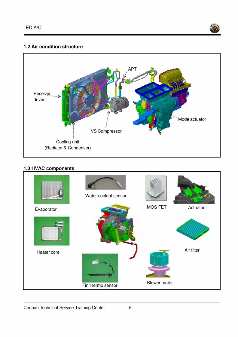
1.2 Air condition structure
1.3 HVAC components
Receiver
driver
Cooling unit
(Radiator & Condenser)
VS Compressor
APT
Mode actuator
Water coolant sensor
MOS FET
Fin thermo sensorBlower motor
Air filter
ActuatorEvaporator
Heater core
Chonan Technical Service Training Center 6

8/9/2019 ED_AIRCON
http://slidepdf.com/reader/full/edaircon 7/17
ED A/C
2. Input and output
Photo sensor
Water coolant sensor
AQS sensor
Vehicle speed sensor
Engine ECM
(PTC heater)
Temperature
actuator
PTC relay
(PTC Heater)
Engine ECM
(Compressor)
MOS FET(Blower motor)
Fin thermo sensor
Ambient sensor
In-car sensor
Humidity sensor
FATC
Intake actuator
Mode actuators
7 Chonan Technical Service Training Center

8/9/2019 ED_AIRCON
http://slidepdf.com/reader/full/edaircon 8/17
ED A/C
3. Main sensors and actuators
3.1 In-car sensor and humidity sensor
In-car sensor
Humiditysensor
DC motor
(1) in-car sensor
The in-car sensor is located on the center facia panel as shown in the picture. It contains a NTC type
thermister, which measures the temperature of the air inside the passenger compartment.
(2) Humidity sensor
Humidity sensor detects the relative humidity of the car’s cabin.
3.2 Ambient sensor
For FATC For trip computer
The ambient temperature sensor is located at the front of the condenser fan. This sensor detects the
temperature of outside air and sends voltage signals to the controller.
Chonan Technical Service Training Center 8
8/9/2019 ED_AIRCON
http://slidepdf.com/reader/full/edaircon 9/17
ED A/C
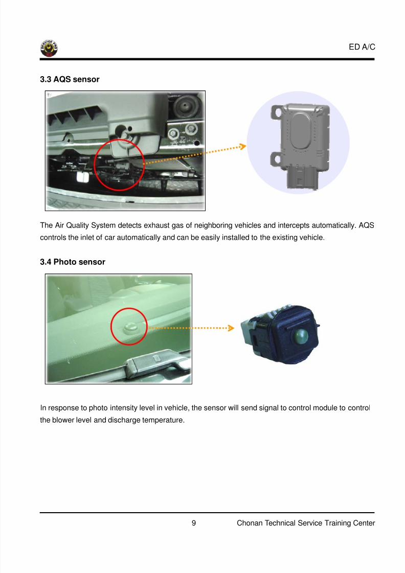
3.3 AQS sensor
The Air Quality System detects exhaust gas of neighboring vehicles and intercepts automatically. AQS
controls the inlet of car automatically and can be easily installed to the existing vehicle.
3.4 Photo sensor
In response to photo intensity level in vehicle, the sensor will send signal to control module to control
the blower level and discharge temperature.
9 Chonan Technical Service Training Center

8/9/2019 ED_AIRCON
http://slidepdf.com/reader/full/edaircon 10/17
ED A/C
3.5 Fin thermo sensor
Compressor: OnCompressor: Off
2.8℃1.3℃
Fin sensor is installed in front of the evaporator in order to detect the temperature of evaporator. It
prevents evaporator from freezing.
3.6 Water coolant temperature sensor
Floor mode actuator
NTC
Water temperature sensor attached to the heater core inlet tube detects the coolant temperature in
the heater core and sends the signal to the controller. The signal becomes data for the controller to
carry out CELO function.
Chonan Technical Service Training Center 10

8/9/2019 ED_AIRCON
http://slidepdf.com/reader/full/edaircon 11/17
ED A/C
3.7 FET (Field Effect Transistor)
Pin No. Functioin
1 Drain (motor feedba
2 Source (ground)
ck)
3 Gate
3.8 APT (Automotive Pressure Transducer)
0
5
1.0 32.6
Approximately 0.2V
Pressure (kg/ ㎠)
O U T P U T ( v o l t )
NormalOperating range
Approximately 4.8V
APT sensor convert the pressure value of high pressure line into voltage value after measure it. By converted
voltage value, engine ECM controls cooling fan by operating it high speed or low speed. ENG ECM stops the
operation of compressor when the pressure (voltage of APT signal) of refrigerant line is too high or too low
irregularly to optimize air conditioning system.
11 Chonan Technical Service Training Center

8/9/2019 ED_AIRCON
http://slidepdf.com/reader/full/edaircon 12/17
ED A/C
3.9 Temperature door actuator
The actuator controls the position of the temperature blend door based on the voltage signal from the
FATC module. Potentiometer, inside of actuator, sends a feedback signal to the controller and
controller cuts off the voltage signal coming from the controller when the required door position is
achieved.
3.10 Mode actuator
The 3 mode actuators (Vent, floor, defrost) allow an occupant to choose the air flow mode to desired
position.
Button Mode FunctionA Vent
A+B Vent + Floor
A+C Vent + Defrost
B+C Floor + Defrost
A+B+C Vent + Floor + Defrost
D Vent + Floor + Defrost Auto mode
Manual mode
D
A B C
Def modeactuator Floor mode
actuator
Vent modeactuator
Mode actuators Air flow
Chonan Technical Service Training Center 12

8/9/2019 ED_AIRCON
http://slidepdf.com/reader/full/edaircon 13/17
ED A/C
20%
30%
50% 25%
25%
50%
Heater Air conditioner
3.11 Air intake actuator
The intake door actuator (fresh/recirculation actuator) allows an occupant to choose between fresh
(outside) air or recirculated inside air by moving the intake (fresh/recirculation) door to the desired
position.
13 Chonan Technical Service Training Center

8/9/2019 ED_AIRCON
http://slidepdf.com/reader/full/edaircon 14/17
ED A/C
3.12 PTC (Positive Temperature Coefficient) heater
3 2 1
PTC heater PTC heater relay
3.13.1 PTC heater operating condition
Engine RPM Above 700 RPM Engine coolant temp Below 70
Intake air temp(MAF) Below 5 Blower motor On
Battery voltage Below 8.9 V: Off
Above 12.5V: On
Operating time Max. 60 minutes
If PTC Heater operation conditions are satisfied, Engine ECM operates PTC heater relay 1, heater/air
conditioner controller receives PTC heater relay 1 operation signal, heater /air conditioner controller
will apply a ground to the control side of relay 2 and 3, allowing the relay contacts to close.
Chonan Technical Service Training Center 14

8/9/2019 ED_AIRCON
http://slidepdf.com/reader/full/edaircon 15/17
ED A/C
4. Logic cancel and selection (Manual A/C)
A. Select DEF mode
B. Push Intake button 5 times within 3 seconds
C. See LED display of intake button flashes 3 times.
D. Logic cancel & selection
5. Temperature unit changeUser may choose the temperature indication between °C and °F.
Press the auto button for 3 seconds during pressing off button.
* Setting unit: °C (Battery disconnection)
Press for 3 seconds or more
Keep pressin
15 Chonan Technical Service Training Center

8/9/2019 ED_AIRCON
http://slidepdf.com/reader/full/edaircon 16/17
ED A/C
6. Diagnosis (using controller button)The FATC module self diagnosis test feature will detect electrical malfunction and provide error codes for
system components with suspected failures.
2. Press 4 times within 2 seconds1.Keep pressing
7. DTC list & failsafe
DTC Description Failsafe
00 Normal
11 In-car temperature sensor open circuit
12 In-car temperature sensor short circuit25℃ Fixed
13 Ambient temperature sensor open circuit
14 Ambient temperature sensor short circuit20℃ Fixed
15 Water temp. sensor open circuit
16 Water temp. sensor short circuit- 2℃ Fixed
17 Evaporator sensor open circuit
18 Evaporator sensor short circuit- 2℃ Fixed
19 Temp actuator feedback line short or open
20 Temp actuator failure
Setting temp.:15 ~ 22.5℃ Max cool
Setting temp.:23 ~ 30℃ Max hot
21 Vent mode actuator feedback line short or open
22 Vent mode actuator failure
If indicator is off : Close
If indicator is on : Open
25 Intake actuator feedback line short or open
26 Intake actuator failure
At FRE mode : Fresh mode fixed
At REC mode : REC mode fixed
27 AQS sensor open
28 AQS sensor short
31 AQS sensor failure
34 Floor actuator feedback line short or open
35 Floor actuator failure
If indicator is off : Close
If indicator is on : Open
36 DEF actuator feedback line short or open
37 DEF actuator failure
If indicator is off : Close
If indicator is on : Open
Chonan Technical Service Training Center 16
8/9/2019 ED_AIRCON
http://slidepdf.com/reader/full/edaircon 17/17
ED A/C