Mounting instructions ED 100, ED 250 ESR —

Welcome message from author
This document is posted to help you gain knowledge. Please leave a comment to let me know what you think about it! Share it to your friends and learn new things together.
Transcript
Mounting instructions
ED 100, ED 250ESR—
ED 100, ED 250—
ESR
2 DORMA
These instructions may only be used in conjunction with the mounting instructions for the ED 100/ED 250 (WN 057698-45532). Especially the safety instructions on page 3 of the ED 100/ED 250 mounting instructions have to be considered!
Contents
Page
1. Preparation of operator at passive leaf 3
2. Preparation of operator at active leaf 4
3. Installation of operators 4 - 5
4. Linking the operators 5 - 6
“Translation of the original operating instructions”
ED 100, ED 250—
ESR
3DORMA
A
1
2
3
4
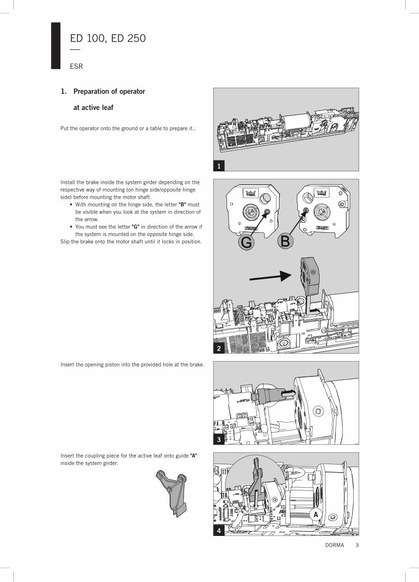
1. Preparation of operator at active leaf
Put the operator onto the ground or a table to prepare it..
Install the brake inside the system girder depending on the respective way of mounting (on hinge side/opposite hinge side) before mounting the motor shaft.
•With mounting on the hinge side, the letter "B" must be visible when you look at the system in direction of the arrow.
• You must see the letter "G" in direction of the arrow if the system is mounted on the opposite hinge side.
Slip the brake onto the motor shaft until it locks in position.
Insert the opening piston into the provided hole at the brake.
Insert the coupling piece for the active leaf onto guide "A" inside the system girder.
ED 100, ED 250—
ESR
4 DORMA
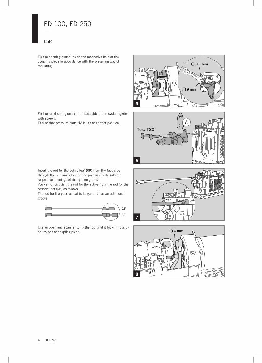
13 mm
9 mm
A
Torx T20
4 mm
5
6
7
8
Fix the opening piston inside the respective hole of the coupling piece in accordance with the prevailing way of mounting.
Fix the reset spring unit on the face side of the system girder with screws.Ensure that pressure plate "A" is in the correct position.
Insert the rod for the active leaf (GF) from the face side through the remaining hole in the pressure plate into the respective openings of the system girder.You can distinguish the rod for the active from the rod for the passive leaf (SF) as follows:The rod for the passive leaf is longer and has an additional groove.
Use an open end spanner to fix the rod until it locks in positi-on inside the coupling piece.
GF
SF
ED 100, ED 250—
ESR
5DORMA
A
B
4 mm
9
10
11
12
13
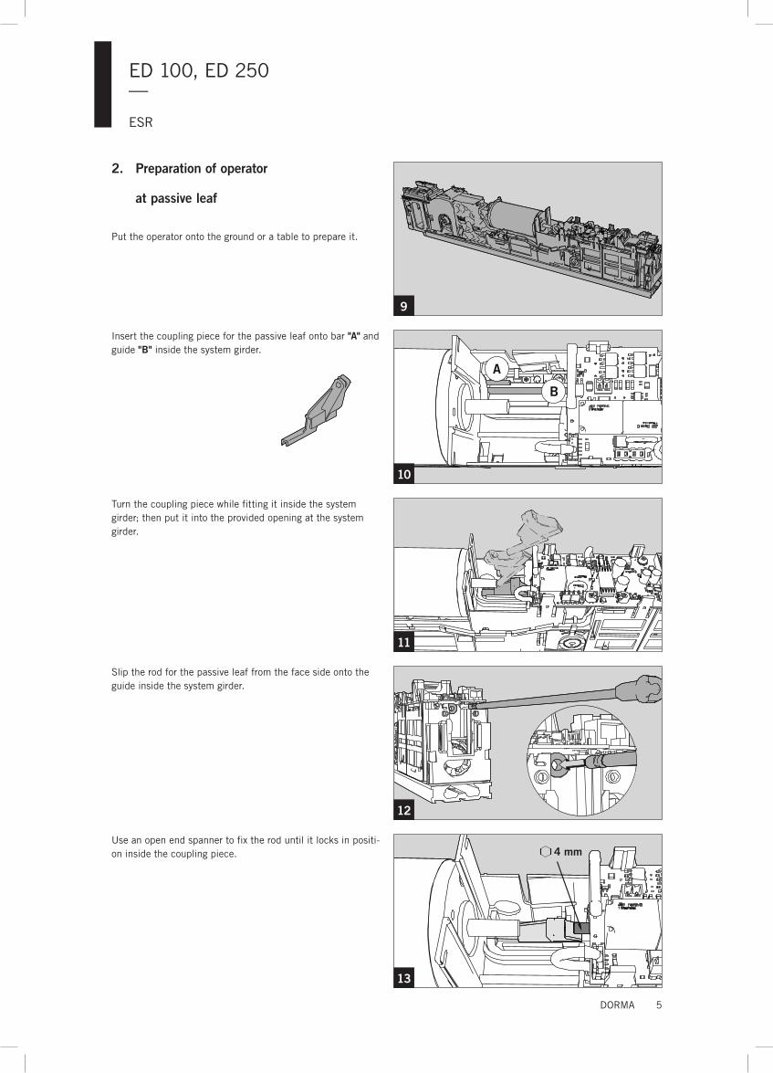
2. Preparation of operator at passive leaf
Put the operator onto the ground or a table to prepare it.
Insert the coupling piece for the passive leaf onto bar "A" and guide "B" inside the system girder.
Turn the coupling piece while fitting it inside the system girder; then put it into the provided opening at the system girder.
Slip the rod for the passive leaf from the face side onto the guide inside the system girder.
Use an open end spanner to fix the rod until it locks in positi-on inside the coupling piece.
ED 100, ED 250—
ESR
6 DORMA
L1
N
A
A + 5mm
14
15
16
17
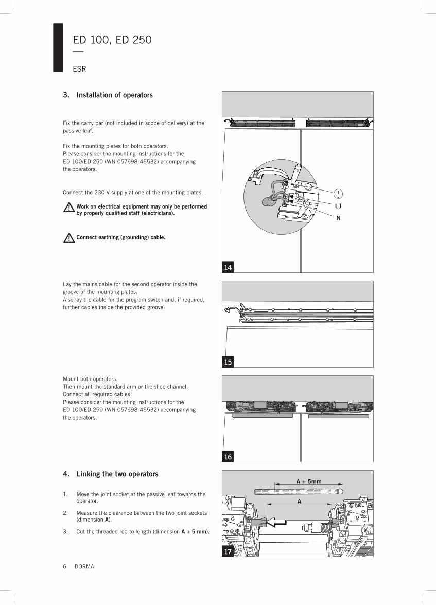
3. Installation of operators
Fix the carry bar (not included in scope of delivery) at the passive leaf.
Fix the mounting plates for both operators.Please consider the mounting instructions for the ED 100/ED 250 (WN 057698-45532) accompanying the operators.
Connect the 230 V supply at one of the mounting plates.
Work on electrical equipment may only be performed by properly qualified staff (electricians).
Connect earthing (grounding) cable.
Lay the mains cable for the second operator inside the groove of the mounting plates.Also lay the cable for the program switch and, if required, further cables inside the provided groove.
Mount both operators.Then mount the standard arm or the slide channel.Connect all required cables.Please consider the mounting instructions for the ED 100/ED 250 (WN 057698-45532) accompanying the operators.
4. Linking the two operators
1. Move the joint socket at the passive leaf towards the operator.
2. Measure the clearance between the two joint sockets (dimension A).
3. Cut the threaded rod to length (dimension A + 5 mm).
ED 100, ED 250—
ESR
7DORMA
2.1.
1 - 2 mm
F
18
19
20
21
22
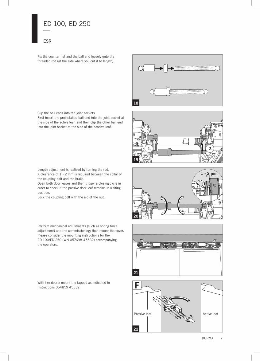
Fix the counter nut and the ball end loosely onto the threaded rod (at the side where you cut it to length).
Clip the ball ends into the joint sockets.First insert the preinstalled ball end into the joint socket at the side of the active leaf, and then clip the other ball end into the joint socket at the side of the passive leaf.
Length adjustment is realised by turning the rod. A clearance of 1 - 2 mm is required between the collar of the coupling bolt and the brake.Open both door leaves and then trigger a closing cycle in order to check if the passive door leaf remains in waiting position.Lock the coupling bolt with the aid of the nut.
Perform mechanical adjustments (such as spring force adjustment) and the commissioning; then mount the cover.Please consider the mounting instructions for the ED 100/ED 250 (WN 057698-45532) accompanying the operators.
With fire doors: mount the tapped as indicated in instructions 054859 45532.
Passive leaf Active leaf
WN
05
8174
45
532, 0
5/1
4, Sub
ject
to
chan
ge w
itho
ut n
otic
e
DORMA Deutschland GmbH
DORMA Platz 1
58256 ENNEPEtAl
GERMANy
tel. +49 2333 793-0
Fax +49 2333 793-4950
www.dorma.com
Related Documents