ECU Catalogue 2016 August 2016

Welcome message from author
This document is posted to help you gain knowledge. Please leave a comment to let me know what you think about it! Share it to your friends and learn new things together.
Transcript

ECU Catalogue 2016
August 2016

WELCOME TO LINK, OR AS WE LIKE TO SAY... THE LABORATORY OF SPEED.
This is the place where exhilaration is made – the exhilaration of unleashing engines, of pushing new boundaries and of having power at your command.
We began 25 years ago, when a group of passionate engineers set out to develop the world’s best race technology. Our vision was to put power, performance and reliability in the hands of drivers and teams, and to push ourselves and our technology as far as possible.
Since then, we’ve become a world leader in Engine Management Technology and our products are sold in 43 countries, by over 1,000 dealers and tuners. Drivers the world over now rely on our ECUs from Australia’s top drag racers, to the Middle East’s biggest drift kings, to Europe’s favourite rally stars; speed freaks all over the world are turning to the race proven Link G4+.
We have a range of products to meet the demands of any driver. From the entry level Atom to the high end Thunder, there is a Link ECU designed for your needs.
SO COME JOIN THE TEAM… YOUR EXHILARATION STARTS HERE.
Exhilaration starts here

02
Link are redefining what an entry level ECU should be.
The Atom now comes in a brand new enclosure, beautifully crafted from glass filled nylon. The stylish new enclosure is designed to IP67 standards, making it dust and waterproof.
Running on the proven Link G4+ platform and being completely waterproof, Link are redefining what an entry level ECU should be.
The Atom is ideal for naturally aspirated engines with 4 cylinders or less that just need a repower and don’t need all the extra sensors and features that come with our higher level ECUs.
Inputs
2 x Digital inputs 2 x Temperature inputs 3 x Analog inputs 2 x Trigger inputs
Outputs
4 x Injection drives 4 x Ignition drivers 4 x Auxiliary outputs* +5V Sensor power supply
* unused ignition drives can also be used as auxiliary outputs
Communications
1x CAN bus 2 x thirty four pin, waterproof connectors 1x USB tuning connection
Misc.
Onboard barometric pressure sensor 32Mb (4 MByte) of logging memory 20 general purpose tables Runs on PC Link software
SPEC OVERVIEW:
The Atom comes supplied with waterproof connectors, a mounting bracket and a USB tuning cable.
02
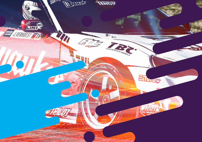
If it is value for money you are after, the Storm is the ECU for you. The Storm offers most of the advanced G4+ tuning features, at an extremely competitive price.
The Storm has more inputs (digital and analogue), as well as more outputs than the Atom, and runs more features like Knock Control, VVT Control, Launch Control and Anti-lag.
The Storm is optimised for naturally aspirated engines with 6 cylinders or less that only need some of the extra sensors and features that come with our higher level ECUs.
Inputs
8 x Digital inputs 3 x Temperature inputs 8 x Analog inputs 2 x Trigger inputs 2 x Knock inputs
Outputs
8 x Injection drives 8 x Ignition drivers 8 x Auxiliary outputs +5V Sensor power supply +8V Sensor power supply
Communications
2 x Thirty four pin, waterproof connectors 1 x CAN bus 1x Serial (RS232) connection 1x USB tuning connection
Misc.
32Mb (4 MByte) of logging memory. Built in trigger oscilloscope. Memo text file for the tuners notes stored within the ECU. QuickTune - automated fuel tuning. Up to 6D fuel and ignition mapping. Precision closed loop cam control (four cam, independent control). Sequential fuel and ignition delivery. Digital triggering, most OEM patterns. Some Motorsport features including antilag, and launch control 5D boost control with three switchable tables. Continuous barometric correction (on board). Resettable statistics recording into on-board memory. Real time selectable dual fuel, ignition and boost maps. Individual cylinder correction. Odd-fire engines & two strokes. Spare injection and ignition channels can be auxiliary outputs. Boost control referenced to gear, speed or throttle position. Sync and crank sensors can be a combination of Hall effect, variable reluctance or optical. Staged injection.
SPEC OVERVIEW:
03

The Xtreme is one of Link’s premium ECU’s with more inputs and outputs, Peak and Hold Injection, built in E-throttle and all the motorsport features including Anti-lag and Traction Control.
The Xtreme is optimised for all engines including V8s, 4 Rotors and turbos. If you want to gain an advantage over the competition, you’ll want a premium ECU like the Xtreme.
Inputs
8/10* x Digital inputs 4 x Temperature inputs 11 x Analog inputs 2 x Trigger inputs 2 x Knock inputs
*2 inputs required when using 2nd CAN Bus
Outputs
8 x Injection drives 8 x Ignition drivers 10 x Auxiliary outputs +5V Sensor power supply +8V Sensor power supply
Communications
2 x Thirty four pin, waterproof connectors 1 x CAN bus 1x Serial (RS232) connection 1x USB tuning connection
Misc.
8 Peak and Hold injection drives, user definable, 10 amp peak, 3 amp hold. Fully programmable E-throttle control complete with gear shift control and throttle blips. CAN is user defined and supports two independent CAN modules Onboard Knock Control - support for two knock sensors wired directly to the ECU. No external amplifier required. 30 General Purpose Tables and many dedicated tables. 100 channels of logging. 32Mb (4 MByte) of logging memory. Built in trigger oscilloscope. Mixture map, closed loop fuel correction. OBDII output stream - send engine data to your tablet or phone using an OBDII to wifi/bluetooth adaptor (not included).
SPEC OVERVIEW:
04

Communications
2 x Thirty four pin, waterproof connectors 1 x CAN bus 1x Serial (RS232) connection 1x USB tuning connection
Misc.
8 Peak and Hold injection drives, user definable, 10 amp peak, 3 amp hold. Fully programmable E-throttle control complete with gear shift control and throttle blips. CAN is user defined and supports two independent CAN modules Onboard Knock Control - support for two knock sensors wired directly to the ECU. No external amplifier required. 30 General Purpose Tables and many dedicated tables. 100 channels of logging. 32Mb (4 MByte) of logging memory. Built in trigger oscilloscope. Mixture map, closed loop fuel correction. OBDII output stream - send engine data to your tablet or phone using an OBDII to wifi/bluetooth adaptor (not included).
If it is Onboard Digital Wideband you are after, then the Fury is the ECU for you. Like the Xtreme, the Fury offers all the features you have come to expect from one of Link's world leading premium ECU's.
The Fury is optimised for engines with 6 cylinders or less and 3 Rotor engines. If you want to gain an advantage over the competition, you’ll want a premium ECU like the Fury.
Inputs
8/10* x Digital inputs 4 x Temperature inputs 9 x Analog inputs 2 x Trigger inputs 2 x Knock inputs
*2 inputs required when using 2nd CAN Bus
Outputs
8 x Injection drives 6 x Ignition drivers 10 x Auxiliary outputs +5V Sensor power supply +8V Sensor power supply
Communications
2 x Thirty four pin, waterproof connectors 1 x CAN bus 1x Serial (RS232) connection 1x USB tuning connection
Misc.
Digital Wideband - superior onboard wideband control giving simple and accurate fuel tuning. Optimised for Six Cylinder / 3 Rotor Engines - the G4+ Fury has 6 x ignition outputs and 8 x fuel outputs. Fully programmable e-throttle control complete with gear shift control and throttle blips. CAN is user defined and supports two independent CAN modules. Onboard Knock Control - support for two knock sensors wired directly to the ECU. No external amplifier required. 30 General Purpose Tables and many dedicated tables. 100 channels of logging. 32Mb (4 MByte) of logging memory. Built in trigger oscilloscope. Mixture map, closed loop fuel correction. OBDII output stream - send engine data to your tablet or phone using an OBDII to wifi/bluetooth adaptor (not included).
SPEC OVERVIEW:
05

Xtreme: 130mm (5.11”)
Thunder: 212mm (8.346”)
06
The Thunder is our biggest, most advanced ECU yet.
The Thunder is optimised for high end applications requiring maximum performance, flexibility and tuning control. The Thunder has more inputs, more outputs and more features than any other Link ECU.Thunder isn’t serious about performance, it’s obsessed.
Inputs
16 x Digital inputs 4 x Temperature inputs 16 x Analog inputs 2 x Trigger inputs 2 x Knock inputs
Outputs
8 x Injection drives 8 x Ignition drivers 18 x Auxiliary outputs +5V Sensor power supply +8V Sensor power supply
Communications
2 x Thirty four pin, waterproof connectors 2 x Twenty eight pin, waterproof connectors 2 x CAN bus 1x Serial (RS232) connection 1x USB tuning connection
Misc.
1 x 3 Axis Accelerometer - Lateral G (cornering), Longitudinal G (acceleration/braking), Vertical G. 2 x K-type Onboard Thermocouple Inputs meaning high accuracy for high temperature situations e.g. exhaust gas temperature sensing. 2 x Digital Wideband Onboard. 2 x E-throttle Controllers - for engines that have two electronic throttle bodies. 2 x Knock Control Inputs - monitor each bank on a V engine. 16 x Digital Inputs - six can be differential reluctor (speed sensor) - ABS wheel speed sensors 16 x Analogue Inputs - Temperature, Pressure, Position. 18 x Auxiliary Outputs - Lights, solenoids, gauges, switches, relays etc. Plus all other G4+ features including all Motorsport, Logging and CAN features, Peak and Hold and Digital Wideband.
SPEC OVERVIEW:

Inputs
8/10* x Digital inputs 4 x Temperature inputs 11 x Analog inputs 2 x Trigger inputs 2 x Knock inputs
*2 inputs required when using 2nd CAN Bus
Outputs
4 x High voltage injector drivers (60V 10/5A Peak/Hold Current). 4 x Ignition drivers 10 x Auxiliary outputs +5V Sensor power supply +8V Sensor power supply
Communications
2 x Thirty four pin, waterproof connectors 1 x CAN bus 1 x Serial (RS232) connection 1 x USB tuning connection
Misc.
1x Ethrottle controller Onboard wideband lambda controller Onboard barometric pressure sensor 32Mb (4 MByte) of logging memory Trigger scope hardware Runs on PC Link software Uses G4+ Motorsport, Logging and CAN features
SPEC OVERVIEW:
The Force GDI is our first ECU built specially to control Gasoline Direct Injection engines. As well as full GDI control, the Force GDI offers on-board digital wideband, E-throttle control, high voltage injector and high pressure fuel pump management, plus all the other features you have come to expect from one of Link's world leading ECUs. The Force GDI is running on our proven Link G4+ platform, so you know it is going to work right out of the box.
07

All LINK PlugIn ECUs run the same powerful micro controller and firmware as the G4+ Thunder, giving you More Horsepower, Launch Control, Traction Control, Gear Shift Control, Anti-Lag, Boost Control and much more.
08
PLUGIN ECUS INSTALLATION:Take your car into a qualified Tuner. They will…
1. Locate the original factory ECU, unplug the loom and remove the enclosure from the car.
2. There are two types of PlugIn ECUs - total replacement or replacement board (PCB).a. Total replacement: The enclosure will fit
in the original ECU location.b. Replacement board: Open the enclosure and remove
the original PCB. Install the G4+ PlugIn. It will fit beautifully. Re-install the enclosure into the car.
3. Plug in the loom.
4. Fit a MAP (Manifold Air Pressure) line from the ECU to the engine’s inlet manifold.
5. Plug the supplied USB cable into a laptop PC and connect using PCLink.
6. Start the engine (it should start immediately and run smoothly) and drive the car onto the dyno.
7. Dyno tune the car to make it the best it can be, all in a minimum of time.
8. Enjoy your car now that it makes exciting power, idles beautifully, starts cleanly and drives smoothly.
G4+ PlugIn boards include an XS Connector that allows the addition of additional inputs/outputs over those included in the vehicles factory harness. The XS connector allows installer to add, for example, switches, boost control, oil pressure etc.
XS Connector Looms are sold separately.
PlugIn ECUs take the hassle out of aftermarket Engine Management. They are a plug in replacement for your factory ECU, with no wiring needed, and are shipped with base maps for a tuner head start.
OVERVIEW

09
PlugIn ECUs take the hassle out of aftermarket Engine Management. ECUs are shipped with base maps for a tuner head start.
MODEL DESCRIPTION PART #
AudiTTLink VWAG 1.8l Turbo e-throttle (A3 1.8T; A4 1.8T) TT+
BMW BMWLink BMW E36 M50TUB25 E36+
MiniLink BMW Mini R53 MINI+
HoldenVLLink Holden VL RB30 HVLC+
HondaCivicLink (95) Honda Civic 1992 - 1995 Gen 5 HC92+
CivicLink (98) Honda Civic 1996 - 1999 Gen 6, HC96+
MazdaRX7Link (S6) Mazda RX7 Series 6, RX7S6+
RX7Link (S7) Mazda RX7 Series 7-8 RX7S7+
MX5Link Mazda MX5 1600-1800 MX5+
MitsubishiEVOLink (I–III) Mitsubishi EVO 1-3 EVO3+
EVOLink (IV–VIII) Mitsubishi EVO 4-8 EVO8+
EVOLink (IX) Mitsubishi EVO 9 EVO9+
VR4Link Mitsubishi VR4 4G63T VR4+
MODEL DESCRIPTION PART #
Nissan300ZLink Nissan 300ZX Z32 N300+
350ZLink Nissan 350Z VQ35DE, 2002-06 N350+
GTRLink Nissan GTR R34 & GTS R32-R33 NGTR+
GTTLink Nissan GTT R34 RB25DET “NEO” NGTT+
S13Link Nissan S13-14, 76 pin NS13+
S15Link Nissan S13-15, 64 pin NS15+
SubaruWRXLink (1-2) Subaru WRX & STI V1-2 WRX2+
WRXLink (3-4) Subaru WRX & STI V3-4 WRX4+
WRXLink (5-6) Subaru WRX & STI V5-6 WRX6+
WRXLink (7-9) Subaru WRX & STI V7-9 WRX9+
WRXLink (04) Subaru WRX & STI V10 04-06 WRX104+
WRXLink (07) Subaru WRX & STI V10 06-07 WRX107+
ToyotaAltezzaLink Toyota Altezza 3SGE TALT+
MR2Link V1 Toyota MR2 V1 & Celica ST185 TST185+
MR2Link V3 Toyota MR2 V2-3 & Celica ST205 TST205+
SupraLink Toyota Supra 2JZ, non VVT TS2JZ+
Volkswagen (AG)TTLink VWAG 1.8l Turbo e-throttle (New Beetle 1.8T; Golf 1.8T; Passat 1.8T) TT+
ECUs

10
Polaris RZR PlugIn Arctic Cat 800 PlugIn
RMK 800 / 163T PlugIn Arctic Cat 1100 PlugIn
Pola
ris
Arct
ic Ca
tRZR 800cc2-Stroke 2011-2014
RMK 800 & 163T 1100cc Turbo(Z1 included) 4-Stroke 2008-2014
> Mount in factory location > Supports the factory dash
> No loom modification required > Unleash your ride’s potential
POWERSPORTS
ECUs

1 1

DASH COMPATIBILITY
DASH2 PRO
ECUs are compatible with all leading after-market dashes
via CAN or serial stream.
Use in competition or road vehicles. The Dash’s construction is of the highest quality with an
aluminium frame and military spec connectors, so it is suitable for both open and closed top vehicles as well as motorcycles.
12
PLUG INTO LINK ECUS > Custom LCD panel dashboard display, clearly visible under any light condition
> Water resistant for open top or motorcycle applications
> Compact and slim, easy to fit > Suitable for any engine installation with a fully configurable RPM scale
> Optimise your gear changes with the configurable ultra bright shift lights
> Road legal, everything required for an MOT or SVA testing including tamper proof odometer, backlit display and mandatory warning lights
> Lap and sector time display using a separate data logger
> Stand alone operation. Connect up to 4 engine or gearbox sensors as well as RPM and wheel speed
> Display information directly from your ECU using CAN or serial interface*
> Monitor your engine and display high/low alarms for any parameter
> Gear position indicator. Calculated or using a gearbox sensor
> User selectable units MPH/miles or KPH/km
> Display the information you want to see with 5 user defined screens
> Control the Dash and a data logger with the external button set (optional)
> Easy to use configuration software
*Link CAN cable required

Link’s new CAN-Lambda is an easy to use CAN-module that provides digital wideband sensor control via CAN bus and is compatible with all leading aftermarket ECUs. The CAN-Lambda’s ability to measure the proportion of oxygen in exhaust gases makes it an essential tool for accurately tuning fuel mixtures as well allowing your ECU to make tuning adjustments on the fly.
Being fully digital the CAN-Lambda’s powerful LSU 4.9 sensor will eliminate any loss of signal, risk, delays and errors that analogue alternatives cause. The CAN-Lambda never requires free air calibration.
CONNECTORS > 1 x 4 pin male DTM connector (power/CAN) > 1 x 6 pin mating connector for LSU 4.9 Lambda sensor
For more information on digital wideband see PG18.
13
CAN-LAMBDA

WHY CHOOSE THE KNOCKLINK OVER OTHER PRODUCTS ON THE MARKET?The KnockLink G4 is the only device on the market that requires no setup. Other systems require time consuming gain, frequency and noise settings to be adjusted. Without proper knock listening tools, this can prove difficult if not impossible. The KnockLink requires none of this, just wire in and start the engine.
Even light detonation will damage an engine over time. The G4 KnockLink’s microprocessor continuously scans the knock signal and warns for any knock occurring. The engine’s RPM and load is automatically 3D profiled by the KnockLink, continuously storing and dynamically adjusting this noise profile map while looking for the particular knock frequency.
If knock does occur, the KnockLink warns the driver with a high intensity red flash. Connect additional sensor (sold separately).
The KnockLink uses advanced signal processing techniques to determine actual engine knock, whilst normal engine noise is completely discarded. It is housed in an anodized black aluminium enclosure, providing sleek looks along with high durability.
TYPICAL CAUSES OF ENGINE KNOCK:Engine knock is one of the most damaging effects in any engine. Detonation (knock) can destroy your engine in seconds. You need to know when knock occurs, instantly.
Knock can happen when there is: > Poor fuel quality > Incorrectly rated spark plugs > Engine cooling problems > Engine management problems
KNOCKLINK
14
The G4 KnockLink Digital Warning is designed for both street and race use and is the only self calibrating knock warning instrument on the market.
FEATURES
> Intelligent self learning digital system > High detection accuracy (90%+ based on feedback from professional tuners)
> No complicated calibration process > Green glow during operation with high intensity red warning flash when knock detected
> Bracket or panel mount
“Ignition timing can make or break an engine and the effects of too much timing or a bad batch of gas can really ruin your day.
The team at Link have been hard at work with knock detection devices and off the back of the G4 KnockBlock comes the G4 KnockLink.
The G4 KnockLink is a stand alone Knock Detection warning light that is simple to install and actually works. I was surprised at how well the KnockLink worked either with factory sensors or noisy engines - the KnockLink picked up detonation that if left alone would have destroyed an engine.
The KnockLink is perfect as a warning device in all cars for that peace of mind as well as a handy tuning tool.” > David Heerdegen Dtech Motorsport
KNOCKBLOCK
15
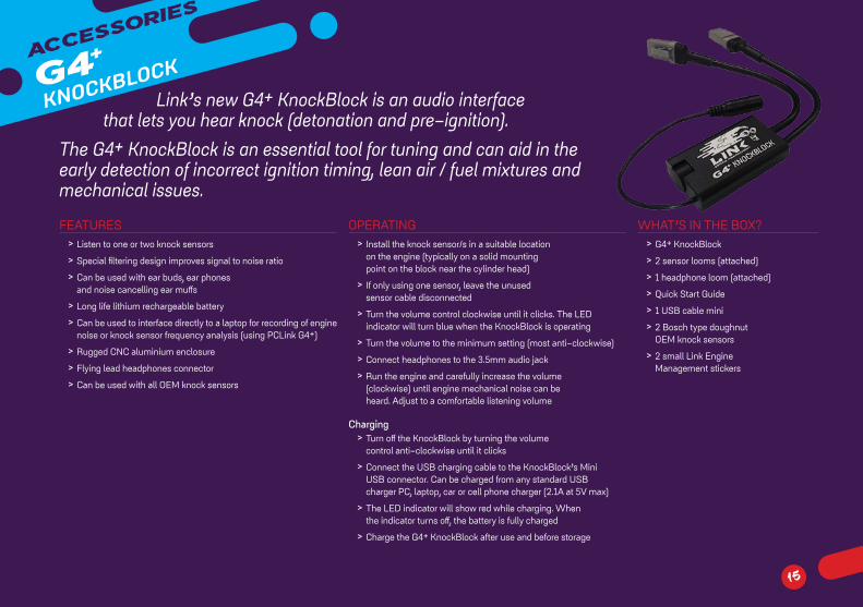
FEATURES > Listen to one or two knock sensors > Special filtering design improves signal to noise ratio > Can be used with ear buds, ear phones and noise cancelling ear muffs
> Long life lithium rechargeable battery > Can be used to interface directly to a laptop for recording of engine noise or knock sensor frequency analysis (using PCLink G4+)
> Rugged CNC aluminium enclosure > Flying lead headphones connector > Can be used with all OEM knock sensors
OPERATING > Install the knock sensor/s in a suitable location on the engine (typically on a solid mounting point on the block near the cylinder head)
> If only using one sensor, leave the unused sensor cable disconnected
> Turn the volume control clockwise until it clicks. The LED indicator will turn blue when the KnockBlock is operating
> Turn the volume to the minimum setting (most anti-clockwise) > Connect headphones to the 3.5mm audio jack > Run the engine and carefully increase the volume (clockwise) until engine mechanical noise can be heard. Adjust to a comfortable listening volume
Charging > Turn off the KnockBlock by turning the volume control anti-clockwise until it clicks
> Connect the USB charging cable to the KnockBlock’s Mini USB connector. Can be charged from any standard USB charger PC, laptop, car or cell phone charger (2.1A at 5V max)
> The LED indicator will show red while charging. When the indicator turns off, the battery is fully charged
> Charge the G4+ KnockBlock after use and before storage
WHAT’S IN THE BOX? > G4+ KnockBlock > 2 sensor looms (attached) > 1 headphone loom (attached) > Quick Start Guide > 1 USB cable mini > 2 Bosch type doughnut OEM knock sensors
> 2 small Link Engine Management stickers
Link’s new G4+ KnockBlock is an audio interface that lets you hear knock (detonation and pre-ignition).
The G4+ KnockBlock is an essential tool for tuning and can aid in the early detection of incorrect ignition timing, lean air / fuel mixtures and mechanical issues.

TUNING > Compatible with all G4+ based ECUs > The most comprehensive, integrated ECU tuning and logging software
> Windows (XP, Vista, 7 & 8) > Mouse or Keyboard driven > Fully configurable multi-page layout
> Large number of different “views” for displaying ECU and log data
> Advanced time saving tuning features and shortcuts
> Single key access to all critical runtime values > Single key to convert metric-imperial
ECU CONFIGURATION > Logically organised tree style navigation of ECU settings > Comprehensive context that is sensitive help for all features
TUNING > Pop-out settings menu that saves screen space > Interactive 3D surface graph > Multiple table display > Configurable gauges, plotting and runtime values > Warnings and Status Information > All runtime displays automatically change based on selected table
GAUGES > A variety of configurable gauge types > Highly visible warnings
LOGGING > Record, save, download and analyse data log files
> Customisable colour themes > Log analysis views: Time Plot, Navigator, XY Plot, Statistics, Histogram, Value List, Parameter List
> Overlay and offset laps and files for comparison
> Global time and cursor linking > Record, analyse and compare logs while tuning an ECU
16

OTHER LANGUAGES
COMPARE BASE MAPS
PCLink has been updated and gained
a really useful feature: compare two base maps and show exactly where the differences are and what has changed. Select a tune from some time ago and compare with today’s tune. Be suspicious, compare the engine’s tune with the tune you kept on file to see if the tune has changed since the car was last in your shop.
Simply open a compare file and it is automatically compared against the currently open file or connected ECU. Changes are highlighted in the settings tree so you can drill down to the exact setting that has been changed.
Download the latest version of PCLink for free from linkecu.com
17
> Alternate between English and Japanese > Coming Soon... Spanish and Mandarin Chinese
>
>

DIGITAL
WIDEBAND
18
OUR CONTROL IS DIGITAL!Other ECU manufacturers use cheap old analogue controllers that are easy and fast for the ECU designers to implement but ignore the capabilities of modern O2 sensors error correction & diagnostics abilities. Worse still, many ECUs and after-market wideband controllers use their own basic, bare bones circuit designs to control the sensor.
The wideband controller IC in the G4+ Fury and G4+ Thunder is so comprehensive, that if we were to build it out of discrete components, it would be as complex as our entire ECU and still not as excellent as the IC we use.
OUR DIGITAL WIDEBAND CONTROLLER > Current OEM technology wideband Lambda sensor control
> Full digital sensor control and interface. No loss of signal measurement precision
> All sensor control is performed using a Digital Signal Processor (DSP) which eliminate risks, delays and measures errors caused by analog alternatives
> Advanced sensor protection such as automatic blackening prevention
> High speed sampling (1.5 kHz) results in fast sensor response - that’s one thousand five hundred samples per second!
> Uses sensors with internal reference cell to prevent drift with ageing
> Advanced sensor and circuit diagnostics not available in analog controllers
> Makes full use of sensor OEM calibration resistor to avoid the need for manual per-sensor calibration
> Continuous measurement, correction and compensation to correct for all wiring, component and circuit errors and changes
> Exhaust temperature correction > Shortest startup to sensor measurement valid time
> Automatic shutoff and protection for sensor wiring short circuits
FUEL EQUATIONSTWO NEW FUEL EQUATIONSTraditional Fuel EquationThe popular, existing fuel equation has been retained allowing tuners to use their existing maps. The traditional fuel equation is recommended for tuners wanting to get an engine tuned promptly for budget customers.
New Fuel Equations1. Modelled Fuel Equation - Tune the Volumetric
Efficiency (VE) table once. Changes not effecting the VE of the engine i.e. injectors, lambda targets, fuel pressures, etc. can be made without having to alter the VE table.
2. Modelled Multi-Fuel Equation - Modelled Fuel Equation (above) plus run any blend of two compatible fuel types and the ECU will inject the correct amount of fuel.
The additional data the ECU receives for the two new modelled fuel modes results in more accurate fueling than the traditional mode.

GEAR SHIFT CONTROLQuick, Smooth Gear Shifting
> Simple clutch (switched) system through to full closed loop sequential gearbox
> Start gear shift control via: » digital input (clutch switch) » gear lever force (H pattern gearbox) » gear lever force (sequential gearbox) or
» gear barrel position sensor
> End gear shift by time, digital input, or gear barrel position
> Configurable for each type of gear shift: » driven up shift » driven down shift » overrun up shift » overrun down shift
> Configure settings per gear > Throttle blip by solenoid or electronic throttle body
> Lockout for engine speed, throttle position, and driven wheel speed
> Gear lever force calibration for strain lever output (volts to newtons)
19
TRACTION CONTROL
Hold on TightNot as simple as it sounds but when its done properly, it is amazing and we sure have done it properly.
Controlled tyre slip to improve vehicle safety, driveability and performance
> Lockout for engine speed, throttle position, and non-driven wheel speed
> Specify the amount of slip per gear before traction control activates, traction control will adjust engine torque to maintain the slip specified
> A second switchable traction control table is available for different road or track conditions
Traction is not available on some ECUs
OTHER FEATURES > Input Shaft Speed - for optimising torque converters and clutches for drag racing
> Latched Launch RPM Mode - rolling race starts
> Multiple VVT Tables - allows for different levels of tune without the need to change base maps
> Rotary Limiting - this new mode reduces exhaust temperatures
> Additional Analog Calibration Tables - 4 more calibration tables
> Push Button - engine start / stop - as used on many modern cars
> Online firmware updates
> OBDII output stream - send engine data to your tablet or phone using an OBDII to wifi/bluetooth adaptor (not included).
MORE

AND MORE
INDIVIDUAL CYLINDER, CLOSED LOOP, KNOCK CONTROLKnock, also known as detonation, refers to the spontaneous combustion of an air/fuel mixture inside a combustion chamber. Knock is induced by excessive pressure within the combustion chamber causing the air/fuel mixture to self detonate. These pressures can be a result of high engine temperature, inappropriate turbo boost pressure, excessive inlet air temperature, and ignition timing which is over advanced.
The Link G4+ ECUs are capable of detecting knock by using factory, or after market knock sensors. By applying user configurable ‘time windowing’ techniques and filtering options, the G4+ will determine which cylinder has knock, and the severity of the knock. 3D knock level threshold tables are used to prevent false detection caused by mechanical engine noise.
Each individual cylinder can be assigned with a 3D knock ignition trim table. These tables are generally spanned using ‘RPM’ and ‘Load’ as their axis, and zones within these tables are modified dynamically by the ECU upon detection of knock. Timing is retarded on detection of knock in the particular zone, using configurable sensitivity and clamping properties. This all happens within the bounds of microseconds.
The G4+ ECU can be configured to gradually re-introduce timing advance, at a rate governed by the speed and delay of which the user has specified in the settings when knock is no longer detected.
UP TO SIX DIMENSIONS OF FUEL & IGNITION TUNINGUnder most circumstances a 3D Fuel Table is sufficient. RPM is typically used for one axis with load (typically represented by MAP or MGP) on another axis. The 3rd axis/dimension is the fuel zone value.
This 3D mapping will be very familiar to the average tuner and the 3D surface representing the fueling can be easily visualised or physically displayed by selecting Surface Graph.
In special cases, 3D mapping may not be adequately flexible to cope with all operating parameters.
Multi-throttle turbo charged engines typically show an example of this. With the throttle wide-open at a MAP value of, for example, 200kPa and an engine speed of 5000rpm the engine will have considerably different fueling requirements than with the throttle half open and the same MAP and engine speed. In this case the 4D Fuel Table table may be used. This second table may be spanned using throttle position on the load axis.
When a 4D/5D/6D table is turned on, its Table Activation mode can be selected. This allows the 4D or 5D Fuel Table to become active only under certain conditions. This is useful if an external switch or switching output is required to activate the table (e.g. switching in the 4D Fuel Table when the nitrous solenoid becomes active). If the table is required to be always active, set this adjustment to Always ON.
As with all tables, 4D and 5D Fuel Tables can have their X and Y axis parameters selected and their row/column locations adjusted.
QUICKTUNE YOUR FUELUsing PCLink, QuickTune is an interactive tuning tool that assists in time efficient fuel tuning. A graphical display of Target AFR (desired AFR) and Actual AFR (measured AFR) is provided. A dual pointer gauge allows the tuner to quickly see how close Actual AFR is to the Target AFR. QuickTune can be setup to operate over the entire fuel table or just over a particular area. QuickTune can be used in Manual or Automatic modes. In Manual mode, QuickTune guides you to cell centering and advises you when is a suitable time to make a fuel table adjustment. With the press of a key a calculated adjustment is made. Often only one or two adjustments are required to tune each cell. In Automatic mode QuickTune does all the adjustments for you. This leaves the tuner free to operate the Dyno or perform other tuning work such as making ignition or cam angle adjustments.
20

21
We stand behind what we sell!LINK ENGINE MANAGEMENT LTD – LIMITED LIFETIME WARRANTY
All Engine Control Units (ECUs) manufactured by Link Engine Management Ltd are subject to the following LIMITED LIFETIME WARRANTIES, and no others.
Link Engine Management Ltd warrants only to the original purchaser of the ECU, for the lifetime of the ECU, (subject to the limitations set out below), that the ECU shall be free from defects of materials and workmanship in the manufacturing process. This warranty ceases to apply and does not apply to ECUs that have not been manufactured by Link Engine Management Ltd for a period of greater than one year.
An ECU claimed to be defective must be returned to the place of purchase. Link Engine Management Ltd, at its sole option, may replace the defective ECU with a comparable new ECU or repair the defective ECU.
This limited lifetime warranty is not transferrable and does not apply to any ECU not properly installed or properly used by the purchaser or end user, or to any ECU damaged or impaired by external forces. The above warranties are the full extent of the warranties available on the ECU. Link Engine Management Ltd has no liability to the original purchaser or any other person for any loss, injury or damage to persons or property resulting from the use of the ECU or any failure of or defect in the ECU whether by general, special, direct, indirect, incidental, consequential, exemplary, punitive, or any other damages of any kind or nature whatsoever. Link Engine Management Ltd specifically disclaims and disavows all other warranties, express or implied, including, without limitation, all warranties of fitness for a particular purpose, warranties of description, warranties of merchantability, trade usage or warranties of trade usage.
For off-road use only, not intended for highway vehicles. This ECU contains a user-configurable software programme, which is updated by Link Engine Management Ltd from time to time. The user must ensure the current correct version of this programme is downloaded from the website of Link Engine Management Ltd and installed in the ECU prior to use. This limited lifetime warranty does not apply where the ECU has been installed with the incorrect version of the software programme. The user is solely responsible for the setup and testing of all user-configurable features.
Link Engine Management Ltd License AgreementThe software programme in this ECU is licensed not sold. Link Engine Management Ltd grants the user a license for the programme only in the country where the programme was acquired. No other rights are granted under this license and the programme may only be used on one machine at a time. If the programme is transferred a copy of this license and all other documentation must be transferred at the same time. The license may be terminated by the user at any time. Link Engine Management Ltd may terminate the licence if the user fails to comply with the terms and conditions of this license. In either event the copy of the programme must be destroyed.
©2016 LINK Engine Management Ltd

ATOM STORM XTREME FURY THUNDER FORCE GDI PLUGIN
Fuel/Ignition Drives 4/4 8/8 8/8 8/6 8/8 4 8/8Digital Inputs 2 8 8/10 8/10 16 10 11Peak & Hold Injection No No 10/3A 10/3A 10/3A 10/5A NoAnalog/Temp Inputs 3/2 8/3 11/4 9/4 16/4 11/4 12/4Auxiliary 4 8 10 10 18 10 16E-Throttle Control No No Yes Yes Yes - Dual Yes YesKnock Control No 2 Channel 2 Channel 2 Channel 2 Channel 2 Channel 2 ChannelOBD Yes Yes Yes Yes Yes Yes Yes+8 Volt Out No Yes Yes Yes Yes Yes NoTrigger Scope No Yes Yes Yes Yes Yes YesLogging Parameters 100 100 100 100 100 100 100Logging Memory 32 Mbit
(c)32 Mbit
(4 MByte)32 Mbit
(4 MByte) 32 Mbit
(4 MByte)32 Mbit
(4 MByte)32 Mbit
(4 MByte)32 Mbit
(4 MByte)CAN 1 Channel 1 Channel 2 Channel 2 Channel 2 Channel 2 Channel 2 ChannelGen Purpose Tables 20 20 30 30 30 30 30RS232 Comms No No Yes Yes Yes Yes YesAux Output on unused Fuel & Ignition Ignition Only Yes Yes Yes Yes Ignition Only YesLambda Sensor Control 0 0 0 1 2 1 0Closed Loop Lambda Auto Mode No No Yes Yes Yes Yes YesDual Closed Loop Lambda (Stoich) No No Yes Yes Yes Yes NoVVT Control No Yes Yes Yes Yes Yes YesSelectable Temp Input Pullups No Yes Yes Yes Yes Yes YesLaunch / AntiLag No Yes Yes Yes Yes Yes YesCruise Control / Traction Control No No Yes Yes Yes Yes YesDiff. Reluctor Interface No No No No 6 No NoThermocouple No No No No 2 No No
2016
Related Documents