SPECIFICATION SUBMITTAL Page Job Name: Job Number: Model Numbers: EcoSystem Five Control Input Digital Dimming Ballasts 369454m 1 03.06.18 Digital electronic dimming ballasts maximize the benefits of a lighting management system. EcoSystem Ballasts offer 100% to 10% dimming; ideal for use where saving energy, increasing flexibility, and maximizing productivity are the goals of the lighting design. Features • Continuous, flicker-free dimming from 100% to 10% • Integral sensor connection provides power for and responds to one occupancy sensor, one photo sensor, and one personal control input (infrared receiver or wallstation) • Communicates status and sensor inputs over the EcoSystem digital link • Programmed rapid start design ensures full rated lamp life while dimming and cycling • Lamps turn on to any dimmed level without flashing to full brightness • Low harmonic distortion throughout the entire dimming range • Frequency of operation ensures that ballast does not interfere with infrared devices • End-of-lamp-life protection circuitry ensures safe operation throughout entire lamp life • Ultra-quiet operation • Non-volatile memory restores all ballast settings after power failure • Ballasts maintain consistent light output for linear lamp lengths (e.g., 4 ft [1.5 m], 3 ft [1 m], 2 ft [0.5 m] have same relative output) • Protected from miswires of any input power to control lead, or from lamp leads to each other and/or ground • 100% performance tested at factory • Custom ballast factors available. Design tool and specifications can be found at www.lutron.com/ballasttool • BAA-compliant (Buy American Act) model numbers available. Add a "U" prefix to the model number EcoSystem case type G EcoSystem case type J EcoSystem Multiple Control Input Ballasts

Welcome message from author
This document is posted to help you gain knowledge. Please leave a comment to let me know what you think about it! Share it to your friends and learn new things together.
Transcript
® SPECIF ICAT ION SUBMITTAL Page
Job Name:
Job Number:
Model Numbers:
EcoSystem Five Control Input Digital Dimming Ballasts
369454m 1 03.06.18
Digital electronic dimming ballasts maximize the benefits of a lighting management system. EcoSystem Ballasts offer 100% to 10% dimming; ideal for use where saving energy, increasing flexibility, and maximizing productivity are the goals of the lighting design.
Features
•Continuous,flicker-freedimmingfrom100%to10%•Integralsensorconnectionprovidespowerforand
responds to one occupancy sensor, one photo sensor, and one personal control input (infrared receiver or wallstation)
•CommunicatesstatusandsensorinputsovertheEcoSystemdigitallink
•Programmedrapidstartdesignensuresfullratedlamp life while dimming and cycling
•Lampsturnontoanydimmedlevelwithoutflashingtofull brightness
•Lowharmonicdistortionthroughouttheentiredimming range
•Frequencyofoperationensuresthatballastdoesnotinterfere with infrared devices
•End-of-lamp-lifeprotectioncircuitryensuressafeoperation throughout entire lamp life
•Ultra-quietoperation•Non-volatilememoryrestoresallballastsettingsafter
power failure•Ballastsmaintainconsistentlightoutputforlinearlamp
lengths (e.g., 4 ft [1.5 m], 3 ft [1 m], 2 ft [0.5 m] have same relative output)
•Protectedfrommiswiresofanyinputpowertocontrollead, or from lamp leads to each other and/or ground
•100%performancetestedatfactory•Customballastfactorsavailable.Designtool
and specifications can be found at www.lutron.com/ballasttool
•BAA-compliant(BuyAmericanAct)modelnumbersavailable.Adda"U"prefixtothemodelnumber
EcoSystem case type G
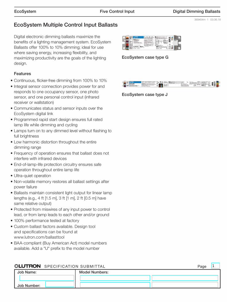
EcoSystem case type J
EcoSystem Multiple Control Input Ballasts

® SPECIF ICAT ION SUBMITTAL Page
Job Name:
Job Number:
Model Numbers:
EcoSystem Five Control Input Digital Dimming Ballasts
369454m 2 03.06.18
Specifications
Regulatory Approvals•ULRListed(evaluatedtotherequirementsofUL935)•CSAcertified(evaluatedtotherequirementsofC22.2No.74)
•SelectballastsareNOMListed(contactLutronformore information)
•SMarkCertified•ClassPthermallyprotected•SomemodelsareaffectedbyCaliforniaTitle20regulation.Californiacustomersmayneedtoorderalternativemodelstocomply.SeeCACustomersectionsonfollowingpagesfordetails.Also,seeCECTitle20RegulationAppNote#601(P/N048601)atwww.lutron.com/title20ballasts for more information
•MeetsANSIC82.11HighFrequencyBallastStandard•ThisdevicecomplieswithPart18(Non-ConsumerLimits)oftheFCCRules.Operationissubjecttothefollowing conditions:(1)Thisdevicemaycauseinterferencetoradio
equipment.(2)Thisdeviceshouldnotbeinstallednearmaritime
safetycommunicationsequipmentorothercriticalnavigationorcommunicationequipmentoperatingbetween0.45–30MHz.
ModificationnotexpresslyapprovedbyLutronElectronicsCo.,Inc.couldvoidtheusersauthoritytooperatethisequipment.ThisNon-ConsumerRFLDcomplieswiththeCanadianstandardICES-005.
•MeetsANSIC62.41CategoryAsurgeprotectionstandardsuptoandincluding4kV
•ManufacturingfacilitiesemployESDreductionpracticesthatcomplywiththerequirementsofANSI/ESD S20.20
•LutronQualitySystemsregisteredtoISO 9001:2008
Environment•Minimumlampstartingtemperature:50°F(10°C)•Relativehumidity:lessthan90%non-condensing•SoundRating:ClassA•Maximumballastcasetemperature:167°F(75°C)
Performance•OperatingVoltage:120,220/240,277 V~ at 50or60 Hz
•Grounding:ballastandfixturemustbegroundedforproper dimming
•DimmingRange:100%to10%measuredrelativelightoutput
•LampStarting:programmedrapidstart•LampCurrentCrestFactor:lessthan1.7•LightOutputVariation:Constant±2%lightoutputforlinevoltagevariationsof±10%
•LampLife:Averagelamplifemeetsorexceeds specified lamp ratings
•PowerFactor:0.95minimum•TotalHarmonicDistortion(THD):Lessthan10%*•MaximumInrushCurrent:3Aperballastat277V~, 7Aperballastat120V~
•Class2Output:+20V-50mAmaximum(onedaylightsensor,onekeypadandoneoccupancysensor can be connected)
Ballast Wiring & Mounting•Ballastisgroundedbyamountingscrewtothefixture•Terminalblocksontheballastacceptthefollowing
wire gauges: –PowerWiring,LampWiring,andEcoSystem
digitallink:onlyone16or18AWG(0.75or1.5mm2) solid per terminal
–Class2Sensors:onlyone22AWG(0.25 mm2) solid per terminal
•Onlyonewireperterminal•Class2sensorwiringmustbeseparatedfromallpowerandClass1wiring,consultallapplicablelocaland national codes
•Ballastmountsusingtwoscrews(orsheetmetalfeature and one screw) within a fluorescent fixture
•Wiringfromtheballasttolampsocketsshouldnotexceed7ft(2m)forT8,T5,andT5HOlamps
•Wiringfromtheballasttolampssocketsshouldnotexceed3ft(1m)forT5TwinTubelamps
Lamp SeasoningRefertolampmanufacturerforlampseasoningrequirementspriortodimming.
*ModelsEC5T514JUNV1andEC5T817JUNV1havelessthan15%THD

® SPECIF ICAT ION SUBMITTAL Page
Job Name:
Job Number:
Model Numbers:
EcoSystem Five Control Input Digital Dimming Ballasts
369454m 3 03.06.18
How to Build a Model Number
Example
E C 5 T 8 3 2 G U N V 2 1 0 L
AB G
HI
CD
E
F
A – Type of Ballast (2 characters)EC=EcoSystemBallast
B – Control Type (1 character)5=5controlinputs:EcoSystemdigitallink,3-wirephasecontrolinput,daylightsensor,
occupancysensor,andpersonalcontrol(IRreceiverorwallstation)
C – Lamp Size (2 characters)T8orT5
D – Lamp Wattage (2 characters)XX=Lampwattage(e.g.54for54Wlamp)
E – Case Type (1 character)GorJ
F – Voltage (3 characters)UNV=Universalvoltage(120 V~,220/240 V~,277 V~)
G – Number of Lamps (1 character)1, 2, or 3
H – Ballast Factor (Blank, 2, or 3 characters)Blank=Default(0.85forT8and1.0forT5)
17=1.17BF
CXX=Customballastfactorof0.XX
I – Optional Power and Lamp Leads (Blank or 1 character)Blank=Noleads
L=Powerandlampleadsincluded(onlyavailableonselectmodelsinGcase)

® SPECIF ICAT ION SUBMITTAL Page
Job Name:
Job Number:
Model Numbers:
EcoSystem Five Control Input Digital Dimming Ballasts
369454m 4 03.06.18
How to Build a Model Number (CA Customers only)
Example
E C 5 N S T 8 3 2 C U 2 1 0 R
AB G
HI
CD
E
F
A – Type of Ballast (2 characters)EC=EcoSystemBallast
B – Control Type (3 characters)5NS=EcoSystemdigitallink,3-wirephasecontrolinput,nosensors1
C – Lamp Size (2 characters)T8orT5
D – Lamp Wattage (2 characters)XX=Lampwattage(e.g.54for54Wlamp)
E – Case Type (1 character)C
F – Voltage (1 character)U=Universalvoltage(120 V~,220/240 V~,277 V~)
G – Number of Lamps (1 character)1, 2, or 3
H – Ballast Factor (2 or 3 characters)10=1.0BF
C85=Customballastfactorof0.85
I - Alternative (1 character)R=Replacement
1Forsensorinputs,usewithaC5-BMF-2A

® SPECIF ICAT ION SUBMITTAL Page
Job Name:
Job Number:
Model Numbers:
EcoSystem Five Control Input Digital Dimming Ballasts
369454m 5 03.06.18
EcoSystem Ballasts with Integral Sensor Connection for Linear and U Bend T8 Lamps
Lamp No. ofLamps
Model CaseSize
InputVoltage(V~)
InputCurrent(A)
InputPower(W)
BallastFactor(BF)
SystemLumens(lm)
SystemEfficacy(lm/W)
BallastEfficacyFactor
RelativeEfficacy(RSE)
F32T8(48in [1219mm])
1 EC5T832JUNV11 J 277240120
0.110.130.26
31.631.031.3
0.850.850.85
255025502550
818281
2.692.742.72
0.860.870.87
2 EC5T832GUNV21 G 277240120
0.210.250.49
59.657.658.8
0.850.850.85
510051005100
868987
1.431.481.45
0.910.940.93
EC5T832GUNV2L1 G 277240120
0.210.250.49
59.657.658.8
0.850.850.85
510051005100
868987
1.431.481.45
0.910.940.93
EC5T832JUNV21 J 277240120
0.210.250.49
57.459.059.1
0.850.850.85
510051005100
898686
1.481.441.44
0.950.920.92
3 EC5T832GUNV3L1 G 277240120
0.310.360.72
86.584.085.9
0.850.850.85
765076507650
888989
0.981.010.99
0.940.970.95
EC5T832GUNV317L1 G 277240120
0.410.470.95
105.7106.5106.8
1.171.171.17
10,53010,53010,530
1009999
1.111.101.10
1.061.051.05
F25T8(36in [914mm])
1 EC5T825JUNV1 J 277240120
0.100.110.23
27.627.026.9
0.850.850.85
182818281828
666868
3.083.153.16
0.770.790.79
2 EC5T825JUNV2 J 277240120
0.160.190.38
44.345.645.6
0.850.850.85
366536653665
757575
1.741.731.73
0.870.870.87
F17T8(24 in [610mm])
1 EC5T817JUNV1 J 277240120
0.070.080.16
19.420.019.2
0.850.850.85
119011901190
686070
4.134.254.23
0.700.720.72
2 EC5T817JUNV2 J 277240120
0.130.150.31
36.237.037.0
0.850.850.85
238023802380
666464
2.352.302.30
0.800.780.78
EcoSystem Ballasts for Linear and U Bend T8 Lamps (CA Customers only)Lamp No. of
LampsModel Case
SizeInputVoltage(V~)
InputCurrent(A)
InputPower(W)
BallastFactor(BF)
SystemLumens(lm)
SystemEfficacy(lm/W)
BallastEfficacyFactor
RelativeEfficacy(RSE)
F32T8(48in [1219mm])
1 EC5NST832CU1C85R2 C 277240120
0.110.130.26
29.530.631.3
0.850.850.85
255025502550
868381
2.882.782.72
0.920.890.87
2 EC5NST832CU2C85R 2 C 277240120
0.220.250.51
61.060.061.2
0.850.850.85
510051005100
848583
1.391.421.39
0.890.910.89
1 NotforsaleinCalifornia-seeCECTitle20RegulationAppNote#601(P/N048601),forinformationonalternativemodels2 Forsensorinputs,usewithaC5-BMF-2A

® SPECIF ICAT ION SUBMITTAL Page
Job Name:
Job Number:
Model Numbers:
EcoSystem Five Control Input Digital Dimming Ballasts
369454m 6 03.06.18
EcoSystem Ballasts for Linear and U Bend T8 Lamps: Reduced Wattage
Lamp No. ofLamps
Model CaseSize
InputVoltage(V~)
InputCurrent(A)
InputPower(W)
BallastFactor(BF)
SystemLumens(lm)
SystemEfficacy(lm/W)
BallastEfficacyFactor
RelativeEfficacy(RSE)
F32T8(48in [1219mm])
1 EC5T8RWJUNV11
30WJ 277
240120
0.110.120.24
28.928.729.2
0.850.850.85
235023502350
818280
2.942.962.91
0.880.890.87
EC5T8RWJUNV11
28W277240120
0.100.110.22
26.326.226.5
0.850.850.85
220222022202
848483
3.233.243.21
0.900.910.90
2 EC5T8RWJUNV21
30WJ 277
240120
0.190.220.44
52.552.553.4
0.850.850.85
470147014701
909088
1.621.621.59
0.970.970.96
EC5T8RWJUNV21
28W277240120
0.180.200.42
48.948.650.0
0.850.850.85
440344034403
909188
1.741.751.70
0.970.980.95
3 EC5T8RWGUNV3L1
30WG 277
240120
0.280.320.65
76.376.378.1
0.850.850.85
705170517051
929290
1.111.111.09
1.001.000.98
EC5T8RWGUNV3L1
28W277240120
0.260.300.60
71.170.471.6
0.850.850.85
660566056605
939492
1.201.211.19
1.001.011.00
Reducedwattagelampsmayexhibitlighttomoderatestriations(movingbandsofbrightanddarkspots)acrossthelampatcertaindimminglevels.Whilestriationsdonotharmthelamporballast,itcanbedistractinginfixtureswherethelampis directly visible.
1 NotforsaleinCalifornia-seeCECTitle20RegulationAppNote#601(P/N048601),forinformationonalternativemodels

® SPECIF ICAT ION SUBMITTAL Page
Job Name:
Job Number:
Model Numbers:
EcoSystem Five Control Input Digital Dimming Ballasts
369454m 7 03.06.18
EcoSystem Ballasts with Integral Sensor Connection for linear T5 Lamps
Lamp No. ofLamps
Model CaseSize
InputVoltage(V~)
InputCurrent(A)
InputPower(W)
BallastFactor(BF)
SystemLumens(lm)
SystemEfficacy(lm/W)
BallastEfficacyFactor
RelativeEfficacy(RSE)
F35T5(57.1in [1450 mm])
1 EC5T535JUNV1 J 277240120
0.150.180.35
42.042.342.2
1.01.01.0
365036503650
878787
2.382.382.38
0.830.830.83
F28T5(45.2 in [1148mm])
1 EC5T528JUNV11 J 277240120
0.120.140.27
32.632.932.9
1.01.01.0
290029002900
898888
3.073.043.04
0.860.850.85
2 EC5T528JUNV21 J 277240120
0.230.270.54
64.565.065.2
1.01.01.0
580058005800
908989
1.551.541.53
0.870.860.86
F21T5(33.4 in [848mm])
1 EC5T521JUNV1 J 277240120
0.090.120.22
25.825.825.8
1.01.01.0
210021002100
818181
3.883.883.88
0.810.810.81
2 EC5T521JUNV2 J 277240120
0.170.200.39
46.047.247.2
1.01.01.0
420042004200
918989
2.172.122.12
0.910.890.89
F14T5(21.6in [549mm])
1 EC5T514JUNV1 J 277240120
0.070.080.16
19.019.219.2
1.01.01.0
135013501350
717070
5.265.215.21
0.740.740.74
2 EC5T514JUNV2 J 277240120
0.120.140.28
32.833.333.3
1.01.01.0
270027002700
828181
3.053.003.00
0.850.850.85
EcoSystem Ballasts for Linear T5 Lamps (CA Customers only)Lamp No. of
LampsModel Case
SizeInputVoltage(V~)
InputCurrent(A)
InputPower(W)
BallastFactor(BF)
SystemLumens(lm)
SystemEfficacy(lm/W)
BallastEfficacyFactor
RelativeEfficacy(RSE)
F28T5(45.2 in [1148mm])
1 EC5NST528CU110R2 C 277240120
0.120.140.28
33.033.633.6
1.01.01.0
290029002900
888686
3.632.982.98
0.850.830.83
2 EC5NST528CU210R2 C 277240120
0.220.260.52
59.862.462.4
1.01.01.0
580058005800
979393
1.671.601.60
0.940.900.90
1 NotforsaleinCalifornia-seeCECTitle20RegulationAppNote#601(P/N048601),forinformationonalternativemodels2 Forsensorinputs,usewithaC5-BMF-2A

® SPECIF ICAT ION SUBMITTAL Page
Job Name:
Job Number:
Model Numbers:
EcoSystem Five Control Input Digital Dimming Ballasts
369454m 8 03.06.18
EcoSystem Ballasts with Integral Sensor Connection for Linear T5 HO Lamps
Lamp No. ofLamps
Model CaseSize
InputVoltage(V~)
InputCurrent(A)
InputPower(W)
BallastFactor(BF)
SystemLumens(lm)
SystemEfficacy(lm/W)
BallastEfficacyFactor
RelativeEfficacy(RSE)
F54T5(45.2 in [1148mm])
1 EC5T554JUNV11 J 277240120
0.210.240.48
56.558.057.9
1.01.01.0
500050005000
888686
1.771.731.73
0.960.930.93
2 EC5T554JUNV21 J 277240120
0.400.520.99
110.1119.0119.3
1.01.01.0
10,00010,00010,000
918484
0.910.840.84
0.980.910.91
F39T5(33.4 in [848mm])
1 EC5T539JUNV1 J 277240120
0.160.180.37
43.344.044.0
1.01.01.0
350035003500
818080
2.312.272.27
0.900.890.89
2 EC5T539JUNV2 J 277240120
0.300.350.70
83.084.084.3
1.01.01.0
700070007000
848383
1.201.191.19
0.940.930.93
F24T5(21.6in [549mm])
1 EC5T524JUNV1 J 277240120
0.110.13 0.24
30.028.828.8
1.01.01.0
200020002000
676969
3.333.473.47
0.800.830.83
2 EC5T524JUNV2 J 277240120
0.200.230.45
54.854.053.9
1.01.01.0
400040004000
737474
1.821.851.86
0.890.890.89
EcoSystem Ballasts for Linear T5 HO Lamps (CA Customers only)Lamp No. of
LampsModel Case
SizeInputVoltage(V~)
InputCurrent(A)
InputPower(W)
BallastFactor(BF)
SystemLumens(lm)
SystemEfficacy(lm/W)
BallastEfficacyFactor
RelativeEfficacy(RSE)
F54T5(45.2 in [1148mm])
1 EC5NST554CU110R2 C 277240120
0.230.260.54
63.762.464.8
1.01.01.0
500050005000
788077
1.571.601.54
0.850.870.83
2 EC5NST554CU210R2 C 277240120
0.430.501.02
119.1120.0122.4
1.01.01.0
10,00010,00010,000
848382
0.840.830.82
0.910.900.88
1 NotforsaleinCalifornia-seeCECTitle20RegulationAppNote#601(P/N048601),forinformationonalternativemodels2 Forsensorinputs,usewithaC5-BMF-2A

® SPECIF ICAT ION SUBMITTAL Page
Job Name:
Job Number:
Model Numbers:
EcoSystem Five Control Input Digital Dimming Ballasts
369454m 9 03.06.18
* Pleaseconsultlampmanufacturersspectodeterminedimmabilityofthereducedwattagelamp.
EcoSystem Ballasts with Integral Sensor Connection for T5 Twin Tube Lamps
Lamp No. ofLamps
Model CaseSize
InputVoltage(V~)
InputCurrent(A)
InputPower(W)
BallastFactor(BF)
SystemLumens(lm)
SystemEfficacy(lm/W)
BallastEfficacyFactor
RelativeEfficacy(RSE)
FT55(20.7in [526mm])
1 EC5T555JUNV1 J 277240120
0.200.230.46
55.455.255.2
0.90.90.9
432043204320
707070
1.621.631.63
0.890.900.90
2 EC5T555JUNV2 J 277240120
0.400.460.92
110.8110.4110.4
0.90.90.9
864086408640
787878
0.810.820.82
0.990.900.90
FT50(22.5 in [572mm])
1 EC5T550JUNV1 J 277240120
0.200.230.45
55.454.054.0
1.01.01.0
400040004000
727274
1.811.851.85
0.900.930.93
2 EC5T550JUNV2 J 277240120
0.360.420.84
99.7100.8100.8
1.01.01.0
800080008000
807979
1.000.990.99
1.000.990.99
FT40(22.5 in [572mm])
1 EC5T540JUNV1 J 277240120
0.160.180.36
44.343.243.2
1.01.01.0
310031003100
707272
2.262.312.31
0.900.930.93
2 EC5T540JUNV2 J 277240120
0.270.320.64
74.876.876.8
1.01.01.0
620062006200
838181
1.341.301.30
1.071.041.04
3 EC5T540GUNV3L G 277240120
0.400.470.95
111.3112.4113.2
1.01.01.0
930093009300
848382
0.900.890.88
1.081.071.06
FT39FT36(15.5 in [394mm])
1 EC5T536JUNV1 J 277240120
0.140.170.33
38.839.639.6
1.01.01.0
285028502850
747272
2.572.532.53
0.930.910.91
2 EC5T536JUNV2 J 277240120
0.260.310.61
72.073.273.2
1.01.01.0
570057005700
797878
1.391.371.37
1.000.980.98
FT25*(22.5 in [572mm])
1 EC5T540RWJUNV1 J 277240120
0.120.140.28
34.334.534.1
1.01.01.0
260026002600
767576
2.912.892.93
0.730.720.73
2 EC5T540RWJUNV2 J 277240120
0.210.250.49
59.361.059.3
1.01.01.0
520052005200
888588
1.681.641.68
0.840.820.84

® SPECIF ICAT ION SUBMITTAL Page
Job Name:
Job Number:
Model Numbers:
EcoSystem Five Control Input Digital Dimming Ballasts
369454m 10 03.06.18
G Case Dimensions
A=9.5 in(241 mm)
B=8.9 in(226 mm)
C=7.1 in(180 mm)
D=1.0 in(25 mm)
E=2.38 in(60 mm)
G Case
EcoSystem Ballast Case Dimensions
Gcaseballastswithleadsshipwith36 in(914 mm)leadsforlampconnectionsand18 in(457 mm)leadsforLine/Hot,Neutral,E1andE2connections
J Case / C Case
ABC D
E
AB
C D
E
F
J Case / C Case Dimensions
A=18.0 in(457 mm)
B=17.68 in(449 mm)
C=6.82 in(173 mm)-JCaseonly
D=0.394 in(10 mm)-JCaseonly
E=1.0 in(25 mm)
F=1.18 in(30 mm)

® SPECIF ICAT ION SUBMITTAL Page
Job Name:
Job Number:
Model Numbers:
EcoSystem Five Control Input Digital Dimming Ballasts
369454m 11 03.06.18
EcoSystem Ballast Wiring Diagrams — T8, T5, T5 HO
Wiring to One Lamp (J case shown)
Wiring to Two Lamps (G case shown)
Blue
Red
Yellow
Wiring to Three Lamps (G case shown)
Blue
Red
Yellow
Striped
NOTICE
•Maximumballasttolampsocketleadlengthis7ft(2m)•Wirecolorsshownarelabeledontheballast,butmayvarydependinguponfixtureconstruction
Wiring to Two Lamps (J case shown)
Blue
Red
Yellow
Blue
Red
BLU
BLU
RED
RED
BLU
BLU
RED
RED
YEL
YEL
BLUBLU
REDRED
YEL
N/C
YEL
N/C
BLUBLU
REDRED
YEL
B/W
YEL
B/W

® SPECIF ICAT ION SUBMITTAL Page
Job Name:
Job Number:
Model Numbers:
EcoSystem Five Control Input Digital Dimming Ballasts
369454m 12 03.06.18
EcoSystem Ballast Wiring Diagrams — T5 Twin-Tube
Wiring to One Lamp
Wiring to Two Lamps
NOTICE
•Maximumballasttolampsocketleadlengthis3 ft(1 m)•Wirecolorsshownarelabeledontheballast,butmayvarydependinguponfixtureconstruction
EcoSystem Ballast Wiring: Power Wiring for EcoSystem Digital Link
1 Ballast is grounded via the case2 WirecolorsshownareforLutroncontrolsandballastsonly.Dimmingcontrolwiresmaynotmatchballastwirecolors3 TheHotmustnotbewiredtoaswitchingdeviceorsystemfunctionalitywillbelost
NEU
DH
HOT
LINE
Class 2 Bus
E1
E2
EcoSystem Ballast
Ground1
Neutral
Line/Hot 2,3
E1
E2
Blue
Red
Yellow
Blue
Red
BLU
BLU
RED
RED
BLU
BLU
RED
RED
YEL
YEL

® SPECIF ICAT ION SUBMITTAL Page
Job Name:
Job Number:
Model Numbers:
EcoSystem Five Control Input Digital Dimming Ballasts
369454m 13 03.06.18
To the EcoSystem digital link & up to 64 total ballasts, drivers, or modules
EcoSystem Ballast Wiring: EcoSystem Digital LinkEcoSystem Digital Link Overview
•TheEcoSystemdigitallinkwiring(E1andE2)connects the ballasts together to form a lighting control system
•EachEcoSystemdigitallinksupportsupto64digitalballasts,64occupantsensors,16daylightsensors,and64wallstationsorIRreceivers
•E1andE2(EcoSystemdigitallinkwires)arepolarity insensitive and can be wired in any topology
•AnEcoSystemEnergiSavrNodedevice, GRAFIKEyeQSwithEcoSystemconnection,orQuantumsystemprovidespowerfortheEcoSystemdigitallinkandsupportssystemprogramming
•AllEcoSystemdigitallinkprogrammingiscompletedbyusingtheEcoSystemProgrammer, GRAFIKEyeQSwithEcoSystemconnection,orQuantumsystem
EcoSystem Digital Link Wiring
•DriverEcoSystemdigitallinkterminalsonlyaccept onesolidwireperterminalfrom18AWGto16AWG (0.75mm2 to 1.5 mm2)
•Makesurethatthesupplybreakertotheballastand EcoSystemdigitallinksupplyisOFFwhenwiring
•Connectthetwoconductorstothetwodriverterminals E1 and E2
•UsingtwodifferentcolorsforE1andE2willreduceconfusion when wiring several ballasts together
•TheEcoSystemdigitallinkmaybewiredClass1orClass2.Consultapplicableelectricalcodesforproperwiring practices
Notes
•TheEcoSystemdigitallinksupplydoesnothave tobelocatedattheendofthedigitallink
•E1andE2wiresarenotpolaritysensitive
•EcoSystemdigitallinklengthislimitedbythewiregauge used for E1 and E2 as follows:
Wire Gauge Digital Link Length (max)
12 AWG 2200 ft
14 AWG 1400 ft
16 AWG 900 ft
18 AWG 550 ft
Wire Size Digital Link Length (max)
4.0 mm2 828 m
2.5 mm2 517 m
1.5 mm2 310 m
1.0 mm2 207 m
0.75 mm2 155 m
BallastTerminals
BallastTerminals
NEUDH
HOT
LINE
Class 2 BusE1
E2
NEUDH
HOT
LINE
Class 2 BusE1
E2

® SPECIF ICAT ION SUBMITTAL Page
Job Name:
Job Number:
Model Numbers:
EcoSystem Five Control Input Digital Dimming Ballasts
369454m 14 03.06.18
EcoSystem Ballast Wiring: Class 2 SensorsElectrical Contractors and Engineers:
•AlwaysfollowapplicablenationalandlocalelectricalcoderequirementswhenconnectingcircuitstoEcoSystem devices
•AllfieldinstalledClass2wiringmustbeseparatedfromlinevoltagewiringbyatleast0.25in(6.4mm)
•SomelocalelectricalcodesrequireClass2wiringtobe separately routed in a metal conduit
•BallastClass2Sensorterminalsonlyaccept 22AWG(0.25 mm2) solid conductors; all other terminalsaccept18AWGto16AWG(0.75mm2 to 1.5 mm2) solid conductors
Lutron Requires:
•KeepClass1andClass2wiringseparate
•Whereseparationisnotpossible,usea600Vinsulatedcablewithaninternalshield.Connecttheshield to ground to provide better noise immunity for low voltage circuits
•RefertoApplicationNote#142foradditionalinformationonEcoSystemdigitallinkClass1andClass2wiring
Fixture Manufacturers:
•ULR15986.17.1allows: Factoryinstalledpowerlimitedwiringandbranchcircuit wiring that come in random contact within the luminaire shall have insulation rated for the maximum voltage that exists in any of the circuits. (EcoSystem ballastcircuitsrequireminimum600Vinsulatedwire)
•ULR15986.17.2.1requires: Luminairesdesignedforthefieldinstallationofpower limited circuits shall be provided with a means ofsegregatingorseparatingthefield-installedpowerlimited circuit wiring from the branch circuit wiring withintheluminaire(seeULR15986.17fordetails)
Lutron Requires:
•KeepClass1andClass2wiringseparate
•Whereseparationisnotpossible,usea600Vinsulatedcablewithaninternalshield.Connecttheshield to ground to provide better noise immunity for low voltage circuits

® SPECIF ICAT ION SUBMITTAL Page
Job Name:
Job Number:
Model Numbers:
EcoSystem Five Control Input Digital Dimming Ballasts
369454m 15 03.06.18
EcoSystem Ballast Wiring: Daylight SensorWiring to a Daylight Sensor
•Sensorwiringsummary:
Sensor Wire Ballast Terminal Terminal ColorRed +20V- Red
Black Common Black
White IR White
Yellow Daylight Yellow
•MakesurethatthesupplybreakertotheDigital BallastisOFFwhenwiring
•ConnectthefourconductorstothefourDigital Ballast terminals as shown
•Themaximumwirelengthfromtheballasttothesensor is 50 ft (15 m)
•BallastClass2terminalsonlyacceptone 22AWG(0.25 mm2) solid wire
Notes
•Consultthedaylightsensorspecificationsheettoproperly position the sensor
•Donotplacethesensorabovependantfixtures,directlybelowlightingfixtures,orwithinskylightwells
•Whenwiringbothawallstationanddaylightsensortooneballast,onlyconnecttheIRwire(white) fromthekeypad.Capoffthewhitewirefromthedaylight sensor
•AllsensorandwallstationwiringisClass2.Followallapplicable national and local codes for proper circuit separation and protection
G Case Terminals
J Case Terminals
Daylight Sensor 22AWG(0.25 mm2) solid only
22AWG(0.25 mm2) solid onlyDaylight Sensor
NEUDHSH
LINE
+20V
Common
IROcc
Daylight
Class 2 (22 AWG Solid)
Class 2 BusE1
E2
+20
VCo
mm
onIR Occ
Day
light
Class 2 (22 AWG Solid)

® SPECIF ICAT ION SUBMITTAL Page
Job Name:
Job Number:
Model Numbers:
EcoSystem Five Control Input Digital Dimming Ballasts
369454m 16 03.06.18
EcoSystem Ballast Wiring: Occupancy Sensor
Wiring to a Lutron Occupancy Sensor (LOS-XX)
•Sensorwiringsummary:
Sensor Wire Ballast Terminal Terminal ColorRed +20V- Red
Black Common Black
Blue Occ Blue
•MakesurethatthesupplybreakertotheDigital BallastisOFFwhenwiring
•Connectthethreeconductorstothethreeballastterminals as shown
•Themaximumwirelengthfromtheballasttothesensor is 50 ft (15 m)
•BallastClass2terminalsonlyacceptone 22AWG(0.25 mm2) solid wire
Notes
•Occupancysensorsfromothermanufacturersmaybeused with EcoSystem ballasts if the sensor meets the following criteria:
Vin=+20V-currentdrawlessthan35mA
•Ifothermanufacturer’soccupantsensorsareusedterminal colors and sensor wire colors may not match
•AllsensorandwallstationwiringisClass2.Followallapplicable national and local codes for proper circuit separation and protection
J Case Terminals
22AWG(0.25 mm2) solid only
OccupancySensor 22AWG(0.25 mm2) solid only
G Case Terminals
OccupancySensor
NEUDHSH
LINE
+20V
Common
IROcc
Daylight
Class 2 (22 AWG Solid)
Class 2 BusE1
E2
+20
VCo
mm
onIR Occ
Day
light
Class 2 (22 AWG Solid)

® SPECIF ICAT ION SUBMITTAL Page
Job Name:
Job Number:
Model Numbers:
EcoSystem Five Control Input Digital Dimming Ballasts
369454m 17 03.06.18
Wiring to an IR Receiver and Wallstation
•Wiringsummary:
Sensor Wire Ballast Terminal Terminal ColorRed +20V- Red
Black Common Black
White IR White
•MakesurethatthesupplybreakertotheDigital BallastisOFFwhenwiring
•ConnectthethreeconductorstothethreeDigital Ballast terminals as shown
•Themaximumwirelengthfromtheballasttothesensor is 50 ft (15 m)
•BallastClass2terminalsonlyacceptone 22AWG(0.25 mm2) solid wire
Notes
•OnlyonewallstationorIRreceivercanbewiredtoadigital ballast
•Ifadaylightsensorandwallstation/IRreceiverareconnected to one ballast, do not connect the daylightsensor’sIRoutput
•AllsensorandwallstationwiringisClass2.Followallapplicable national and local codes for proper circuit separation and protection
22AWG(0.25 mm2) solid only
G Case Terminals
IRReceiver
J Case Terminals
22AWG(0.25 mm2) solid only
IRReceiver
Wallstation
WirestoDigitalBallast
NEUDHSH
LINE
+20V
Common
IROcc
Daylight
Class 2 (22 AWG Solid)
Class 2 BusE1
E2
+20
VCo
mm
onIR Occ
Day
light
Class 2 (22 AWG Solid)
EcoSystem Ballast Wiring: IR Receiver and Wallstation

® SPECIF ICAT ION SUBMITTAL Page
Job Name:
Job Number:
Model Numbers:
EcoSystem Five Control Input Digital Dimming Ballasts
369454m 18 03.06.18
EcoSystem Ballast Wiring: Multiple DevicesMultiple Sensors with One Ballast
•EcoSystemballastsacceptwiringforonedaylight sensorinput,oneoccupantsensorinputandoneIRinput(wallstationorIRreceiver)
•EcoSystemdaylightsensorshaveIRoutputsthat allow the device to operate as a programming port. Inapplicationswhereadaylightsensorand wallstation are wired to the same ballast, do not connect the white wire of the daylight sensor to theballast.Thewallstationoperatesasthe programmingportthroughitsintegralIRreceiver
•Usethechartbelowasaguideforwiringmultipledevices to a ballast
How to Use the Chart
Connectasensortoaballastfromthe“Devices”column(inbold).Alongtheselecteddevicerow,are“Y’s”and“N’s”.Wherea“Y”isplaced,thedevice at the top of that column can also be connected to the same ballast.An“N”indicatesnoconnectionallowed.
Devices Daylight Sensor (with IR)
Occupant Sensor
Wallstation or
IR receiver
Daylight Sensor (no IR)
Daylight Sensor(with IR) Y N N
OccupantSensor Y Y Y
Wallstation orIR Receiver N Y Y
Daylight sensor(no IR) N Y Y
Example: When a Daylight Sensor with IR is connected to a ballast, then only an occupancy sensor can be added for the system to properly function.
J Case Terminals
+20
VCo
mm
onIR Occ
Day
light
Class 2 (22 AWG Solid)

® SPECIF ICAT ION SUBMITTAL Page
Job Name:
Job Number:
Model Numbers:
EcoSystem Five Control Input Digital Dimming Ballasts
369454m 19 03.06.18
EcoSystem Ballast Wiring: Line Voltage DimmersEcoSystem Ballasts and 3-wire dimmers
•Lutron3-wiredimmersonlycontroltheballasttheyare wired to; EcoSystem ballasts do not support groupingof3-wirecontrolinput
3-Wire Control Wiring
•MakesurethatthesupplybreakertotheDigital BallastisOFFwhenwiring
•Wireasshown
Line input Connects toHot DimmerBlackWire
Neutral DimmerWhiteWire
Dimmer wire Connects toYellow BallastOrange(DH)
Red BallastBlack(HOT)
White BallastWhite(NEU)
Green EarthGround
•EcoSystemballastlinevoltageand3-wireinput terminalsonlyacceptone18to16AWG (0.75to1.5mm2) solid wire
Emergency and 3-wire
•EcoSystemballastscontrolledbyawallboxdimmershould not be used for emergency/egress lighting unless an external emergency ballast is used in the fixture.SeeLutronApplicationNote#50at www.lutron.com
•EcoSystemballastsmaybeusedforemergency/egresslightingwhencontrolledbyaLutrondimmingpanel(GP);wherethepanelisadedicated emergency panel
Notice
3-Wirecontrolturnsoffdigitalballastswhenthecontrolisintheoffposition.Thedigitalballastinputs(daylight sensor, wallstation, occupant sensor, and IRreceiver)willnotfunctionwhenthedigitalballastis turned off.
LUTRON
3-WireDimmer Green
Ground
Red
Yellow
White
Neutral
Line/Hot
White
Orang
e
Black
NEUDH
HOT
LINE
Class 2 Bus
E1E2
LINE
Class 2 BusE1
E2
NEUDH
HOT

® SPECIF ICAT ION SUBMITTAL Page
Job Name:
Job Number:
Model Numbers:
EcoSystem Five Control Input Digital Dimming Ballasts
369454m 20 03.06.18
ATTENTION ELECTRICIANS AND CONTRACTORSBallast/Socket Leads
Leadlengthsfromballasttosocketmustnotexceed7ft(2m)forlinearlamps(T5,T5HO,T8).Leadlengthsmustnotexceed3ft(1m)forT5twintubelamps.
Lamp Sockets
LampsocketsasperIEC 60400arerequiredtoensurepositivelamp-pintosocketcontact.
Lamp Mounting
Manyfluorescentlampsocketsareavailablewithmounting slots to vary the height of the lamp away fromthegroundedmetalsurface.Havingafluorescent lamp too close to the grounded metal will reducelamplife.Havingafluorescentlamptoofarawayfromthegroundedmetalwillmakethelampflickerornotturnonatall.Pleasenotethatallofthelamp heights are measured between the grounded metal surface and the glass wall of the lamp.
Mounting for T8 Lamps
Mountlamps1/8to3/4in(3.2to19mm)awayfromthe grounded metal surface.
Mounting for T5 and T5HO Lamps
Mountlamps1/16into3/8in(1.6mmto9.5mm)away from the grounded metal surface.
Mounting for T5 Twin Tube Lamps
Mountlamps1/16into1/2in(1.6mmto13mm)awayfrom the grounded metal surface.
Ballast Operating Temperature
Ballastcasetemperaturemustnotexceed167°F
(75°C)atanypointonballast.
Cold Air Flow
Ensurethatnocoldair(fromHVACsystem,etc)isblowingacrossthelamps.CoolingthelampwillcauseperformanceissuesasnotedinNEMALSD-34.
ATTENTION FACILITIES MANAGERS
Lamp Seasoning Requirements
Some fluorescent lamp manufacturers recommend that new fluorescent lamps be operated at full output (“seasoned”)beforetheycanbedimmed, to render lamp impurities inert, ensuring proper dimming performance and average rated lamp life. Pleasecontactyourlampmanufacturerforseasoningrequirements.
SERVICE
Replacement Parts
UsereplacementpartswithexactLutronmodelnumbers.ConsultLutronifyouhaveanyquestions.
Further Information
Forfurtherinformation,pleasevisitusat www.lutron.com/ballastsorcontactLutron CustomerAssistanceat1.844.LUTRON1
IMPORTANT: Lamps must never touch ground plane and should be placed without obstruction.
Lamp Lamp Socket(side view)
Mounting height
Grounded metalBallast
LutronandGRAFIKEyeQSaretrademarksLutronElectronicsCo.,Inc.registeredintheU.S.andothercountries.EnergiSavrNodeisatrademarkofLutronElectronicsCo.,Inc.ULisatrademarkofULLLC.
Related Documents