OTCREOS11.1-39-F E CONOMIC E NHANCEMENT THROUGH I NFRASTRUCTURE S TEWARDSHIP I NVESTIGATION OF O PTIMIZED G RADED C ONCRETE FOR O KLAHOMA D ANIEL C OOK A SHKAN G HAEEZADEH T YLER L EY , P H .D., P.E. Phone: 405.732.6580 Fax: 405.732.6586 www.oktc.org Oklahoma Transportation Center 2601 Liberty Parkway, Suite 110 Midwest City, Oklahoma 73110

Welcome message from author
This document is posted to help you gain knowledge. Please leave a comment to let me know what you think about it! Share it to your friends and learn new things together.
Transcript

OTCREOS11.1-39-F
ECONOMIC ENHANCEMENT THROUGH INFRASTRUCTURE STEWARDSHIP
INVESTIGATION OF OPTIMIZED GRADED
CONCRETE FOR OKLAHOMA
DANIEL COOK ASHKAN GHAEEZADEH
TYLER LEY, PH.D., P.E.
Phone: 405.732.6580
Fax: 405.732.6586
www.oktc.org
Oklahoma Transportation Center
2601 Liberty Parkway, Suite 110
Midwest City, Oklahoma 73110

DISCLAIMER The contents of this report reflect the views of the authors, who are responsible for the facts and accuracy of the information presented herein. This document is disseminated under the sponsorship of the Department of Transportation University Transportation Centers Program, in the interest of information exchange. The U.S. Government assumes no liability for the contents or use thereof.
i

TECHNICAL REPORT DOCUMENTATION PAGE 1. Report No. 2. Government Accession No. 3. Recipient’s Catalog No. OTCREOS11.1-39-F
4. Title and Subtitle 5. Report Date Investigation of Optimized Graded Concrete for Oklahoma July 2013
6. Performing Organization Code
7. Author(s) Daniel Cook, Ashkan Ghaeezadeh, Tyler Ley
8. Performing Organization Report No.
9. Performing Organization Name and Address 10. Work Unit No. (TRAIS) Oklahoma State University School of Civil and Environmental Engineering 207 Engineering South Stillwater, OK 74078
11. Contract or Grant No.
DTRT06-G-0016
12. Sponsoring Organization Name and Address 13. Type of Report and Period Covered
Oklahoma Transportation Center (Fiscal) 201 ATRC Stillwater, OK 74078 (Technical) 2601 Liberty Parkway, Suite 110 Midwest City, Oklahoma 73110
Final Report, Aug 2012 – Aug 2013 14. Sponsoring Agency Code
15. Supplementary Notes Project performed in cooperation with the Oklahoma Transportation Center and the University Transportation Center Program 16. Abstract This report presents the results of several novel test methods to investigate concrete for slip formed paving. These tests include the Box Test, a novel test to evaluate the response of concrete to vibration, the AIMS2, an automated test for aggregate shape and texture, and the use of a pan mixer to serve as a concrete rheometer. The results show that both the Box Test and AIMS2 tests seem to be useful and provide reliable data. The pan mixer results do not appear to be reliable. The establishment of these test procedures provides a basis for future investigations of materials and mixtures from the state of Oklahoma.
17. Key Words 18. Distribution Statement optimized graded concrete, concrete mixture design, AIMS, aggregate investigation, rheology, the Box Test,
No restrictions. This publication is available at www.oktc.org and from the NTIS.
19. Security Classification (of this report)
20. Security Classification (of this page)
21. No. of Pages 22. Price
Unclassified. Unclassified. 72 + covers
ii

SI (METRIC) CONVERSION FACTORS
Approximate Conversions to SI Units
Symbol When you know
Multiply by
LENGTH
To Find Symbol
in inches 25.40 millimeters mm
ft feet 0.3048 meters m
yd yards 0.9144 meters m
mi miles 1.609 kilometers km
AREA
in² square
inches 645.2
square
millimeters mm
ft² square
feet 0.0929
square
meters m²
yd² square
yards 0.8361
square
meters m²
ac acres 0.4047 hectares ha
mi² square
miles 2.590
square
kilometers km²
VOLUME
fl oz fluid
ounces 29.57 milliliters mL
gal gallons 3.785 liters L
ft³ cubic
feet 0.0283
cubic
meters m³
yd³ cubic
yards 0.7645
cubic
meters m³
MASS
oz ounces 28.35 grams g
lb pounds 0.4536 kilograms kg
T short tons
(2000 lb) 0.907 megagrams Mg
TEMPERATURE (exact)
ºF degrees
Fahrenheit
(ºF-32)/1.8 degrees
Celsius
ºC
FORCE and PRESSURE or STRESS
lbf poundforce 4.448 Newtons N
lbf/in² poundforce
per square inch
6.895 kilopascals kPa
Approximate Conversions from SI Units
Symbol When you know
Multiply by
LENGTH
To Find Symbol
mm millimeters 0.0394 inches in
m meters 3.281 feet ft
m meters 1.094 yards yd
km kilometers 0.6214 miles mi
AREA
mm² square
millimeters 0.00155
square
inches in²
m² square
meters 10.764
square
feet ft²
m² square
meters 1.196
square
yards yd²
ha hectares 2.471 acres ac
km² square
kilometers 0.3861
square
miles mi²
VOLUME
mL milliliters 0.0338 fluid
ounces fl oz
L liters 0.2642 gallons gal
m³ cubic
meters 35.315
cubic
feet ft³
m³ cubic
meters 1.308
cubic
yards yd³
MASS
g grams 0.0353 ounces oz
kg kilograms 2.205 pounds lb
Mg megagrams 1.1023 short tons
(2000 lb) T
TEMPERATURE (exact)
ºC degrees
Celsius
9/5+32 degrees
Fahrenheit
ºF
FORCE and PRESSURE or STRESS
N Newtons 0.2248 poundforce lbf
kPa kilopascals 0.1450 poundforce
per square inch
lbf/in²
iii

ACKNOWLEDGMENTS The research team would like to thank Ralph Browne of Brown and Gay Engineering for his review and suggestions of the work. His feedback was quite helpful in keeping the research team focused. In addition great comments and feedback was provided by Gary Fick of Trinity Construction. In addition the oversight provided by Kenny Seward of ODOT was invaluable to ensure that the research was applicable to the state of Oklahoma.
iv

Investigation of Optimized Graded
Concrete for Oklahoma
Final Report: July, 2013
Daniel Cook Ashkan Ghaeezadah Tyler Ley, Ph.D., P.E.
Oklahoma State University Civil and Environmental Engineering Department
207 Engineering South Stillwater, OK 74078
Oklahoma Transportation Center Tinker Business & Industrial Park 2601 Liberty Parkway, Suite 110 Midwest City, Oklahoma 73110
v
TABLE OF CONTENTS
CHAPTER 1 – INTRODUCTION ................................................................ 1
CHAPTER 2–THE BOX TEST .................................................................... 2
Current Laboratory Tests for the Workability of Concrete ....................................... 2
The Slump Test (ASTM C 143) ............................................................................ 3
The Vebe Apparatus test ...................................................................................... 3
The Vibrating Slope Apparatus ............................................................................. 4
Objectives ............................................................................................................... 4
Materials ................................................................................................................. 4
Mixture Design ........................................................................................................ 8
Mixing and Testing Procedure .............................................................................. 10
Development of the Box Test ................................................................................ 10
Overview of the Box Test ................................................................................... 12
The Box Test Procedure ..................................................................................... 16
Results of Validating the Box Test ........................................................................ 18
Effects of Sequential Dosage ............................................................................. 19
Repeatability of a Single Operator Replication ................................................... 19
Comparison of Multiple Operators ...................................................................... 20
Multiple Evaluators ............................................................................................. 21
Field Performance .............................................................................................. 21
Evaluating Gradations Using the Box Test ......................................................... 21
Discussion ............................................................................................................. 23
Effects of Sequential Dosage ............................................................................. 24
Repeatability of a Single Operator Replication ................................................... 24
Comparison of Multiple Operators ...................................................................... 24
Multiple Evaluators ............................................................................................. 24
Applying the Box Test ......................................................................................... 25
Slump and Box Test Measurement .................................................................... 25
Improvements to the Box Test ............................................................................ 25
Practical Implications .......................................................................................... 26
vi

Conclusion ............................................................................................................ 26
Chapter 3 - Use of a Concrete Mixer to Evaluate the Rheology of low Slump Concrete Mixtures ....................................................................... 28
Introduction ........................................................................................................... 28
Experimental Methods .......................................................................................... 29
Material ............................................................................................................... 29
Mixture Design .................................................................................................... 31
Mixing and Testing Procedure .............................................................................. 31
Pan Mixer ........................................................................................................... 31
Mixing procedure ................................................................................................ 32
Using the Pan-Mixer to Measure the Rheology of the Concrete ......................... 33
Results .................................................................................................................. 34
Discussion: ............................................................................................................ 37
Conclusion ............................................................................................................ 37
CHAPTER 4 – INVESTIGATION OF AGGREGATE CHARACTRISTICS FOR CONCRETE WITH THE AIMS II ...................................................... 38
Introduction ........................................................................................................... 38
Materials ............................................................................................................... 39
Testing Procedure using the AIMS II ..................................................................... 42
Coarse Aggregate Specific Measurements ........................................................ 42
Gradient Angularity......................................................................................... 43
Texture ........................................................................................................... 44
Sphericity ....................................................................................................... 45
Flat & Elongated, Flat or Elongated................................................................ 46
Coarse Aggregate Angularity Texture Value (CAAT) ..................................... 46
Form 2D ......................................................................................................... 47
Results .................................................................................................................. 48
Discussion ............................................................................................................. 52
Texture ............................................................................................................... 52
Angularity ........................................................................................................... 53
vii

Sphericity ............................................................................................................ 53
Flat & Elongated ................................................................................................. 53
Angularity of Fine Aggregate .............................................................................. 54
Form 2D ............................................................................................................. 54
Conclusion ............................................................................................................ 54
CHAPTER 5 – CONCLUSION .................................................................. 56
CHAPTER 6 – FUTURE WORK ............................................................... 57
REFERENCES ......................................................................................... 58
viii

LIST OF FIGURES FIGURE 1 - SIEVE ANALYSIS FOR EACH AGGREGATE TYPE. ................................. 7 FIGURE 2 - COMPONENTS OF A SLIP FORMED PAVER. ........................................ 11 FIGURE 3 - ISOLATING A VIBRATOR IN A SECTION OF CONCRETE. .................... 12 FIGURE 4 - THE BOX TEST VOLUMETRIC DIMENSIONS. ........................................ 12 FIGURE 5 - DIFFERENT COMPONENTS OF THE BOX TEST. .................................. 13 FIGURE 6– A VISUAL REPRESENTATION OF TOP AND BOTTOM EDGE
SLUMPING. ........................................................................................................... 16 FIGURE 7 - A FLOW CHART OF THE BOX TEST PROCEDURE. .............................. 18 FIGURE 8 - COMBINED GRADATION OF SAND TO INTERMEDIATE AND COARSE
AGGREGATE. ....................................................................................................... 22 FIGURE 9 - COMBINED GRADATIONS OF INTERMEDIATE TO COARSE WITH
CONSTANT SAND AMOUNTS. ............................................................................. 23 FIGURE 10 - SIEVE ANALYSIS FOR EACH AGGREGATE TYPE. ............................. 30 FIGURE 11- THE DIFFERENT COMPONENTS OF THE PAN-MIXER. ....................... 32 FIGURE 12 –THE PAN MIXER SPEED INTERVALS WITH INCREASING AMOUNTS
OF WR. .................................................................................................................. 34 FIGURE 13 –CHANGES IN TORQUE USING A WR. ................................................... 35 FIGURE 14– MEASURING TORQUE AT THREE INTERVAL SPEEDS WITH NO WR.
............................................................................................................................... 35 FIGURE 15 –FIRST WR DOSAGE MEASURING TORQUE AT THE INTERVAL
SPEEDS. ............................................................................................................... 36 FIGURE 16- SECOND WR DOSAGE MEASURING TORQUE AT THE INTERVAL
SPEEDS. ............................................................................................................... 36 FIGURE 17- SIEVE ANALYSIS OF EACH AGGREGATE BEING ANALYZED BY THE
AIMS II. .................................................................................................................. 41 FIGURE 18 - GRADIENT VECTOR FOR SMOOTH VS. ANGULAR PARTICLE25. ...... 43 FIGURE19 - FINE AND COARSE AGGREGATE ANGULARITY RANGES26. .............. 44 FIGURE 20 - COARSE AGGREGATE TEXTURE RANGE .......................................... 45 FIGURE 21 - CLUSTER CLASSIFICATION CHARTS FOR DIFFERENT AGGREGATE
PROPERTIES23. .................................................................................................... 46 FIGURE 22 - FINE AGGREGATE FORM 2D RANGES. ............................................... 48 FIGURE 23 – AIMS MEASURING TEXTURE INDEX OF COARSE AGGREGATE. .... 49 FIGURE 24- AIMS MEASURING ANGULARITY OF COARSE AGGREGATE. ............ 50 FIGURE 25 –AIMS MEASURING THE SPHERICITY INDEX OF COARSE
AGGREGATE. ....................................................................................................... 50 FIGURE 26 - AIMS MEASURING FLAT AND ELONGATED OF COARSE
AGGREGATE ........................................................................................................ 51 FIGURE 27 - AIMS MEASURING THE ANGULARITY OF FINE AGGREGATES. ....... 51 FIGURE 28 – AIMS MEASURING THE FORM 2D INDEX OF FINE AGGREGATE..... 52
ix

LIST OF TABLES TABLE 1 –THE OXIDE ANALYSIS FOR THE CEMENT USED IN THE STUDY. ........... 5 TABLE 2 –DESCRIPTION OF THE AGGREGATES IN THE STUDY. ............................ 6 TABLE 3–SUMMARY OF THE MIXTURE DESIGNS FOR THIS CHAPTER (ALL UNITS
WEIGHTS ARE GIVEN IN LBS/YD³). ...................................................................... 9 TABLE 4 - THE DIFFERENT STEPS OF THE BOX TEST. .......................................... 14 TABLE 5 - THE BOX TEST RANKING SCALE. ............................................................ 15 TABLE 6– COMPARISON OF SINGLE AND MULTIPLE DOSAGES. .......................... 19 TABLE 7 - SINGLE OPERATOR REPEATABILITY. ..................................................... 20 TABLE 8. MULTIPLE OPERATORS COMPARISON.................................................... 20 TABLE 9– COMPARISON OF MULTIPLE EVALUATORS USING THE BOX TEST. ... 21 TABLE 10 – THE OXIDE ANALYSIS FOR THE CEMENT USED IN THE STUDY. ...... 29 TABLE 11– THE BATCH WEIGHT USED. ................................................................... 31 TABLE 12 – SOURCE TYPE AND NAME OF EACH AGGREGATE INVESTIGATED. 40
x

Executive Summary
The goal of this research was to develop tools to better understand the complex
relationship between the workability of concrete and aggregate gradation and
characteristics in concrete mixture design. Currently, a limited amount of guidance has
been produced on this topic. Furthermore, the small amount of guidance being used is
not backed up by much experimental data. This work specifically investigates three
different tools to help with this situation. They include the investigation of the response
of a concrete mixture to vibration, the use of a concrete pan-mixer to evaluate the
rheology of a concrete mixture, and the use of the AIMS II unit to investigate the
characteristics of aggregates.
While not all these studies were a success, some of this work shows a great deal
of promise for the future. A real effort was made in this work to investigate the
robustness of these tests and to establish valid measurements techniques. This work is
an outstanding foundation for work that is ongoing for the Oklahoma Department of
Transportation to develop new aggregate gradation standards for the state of
Oklahoma.
An outline of the finding of this work is give below:
• Results show that the Box test is a useful and repeatable tool to evaluate
different mixtures for a slip formed pavement.
• The Box Test was able to show that the gradation of a mixture influenced the
response to vibration. While the amount of coarse and intermediate aggregate
largely varied with only a little change in workability, a small change in the
amount of sand significantly affected the workability of the mixture.
• While the Slump Test does not provide a consistent measuring tool for low slump
concrete, the Box test can be a useful tool.
• However, the repeatability of the pan-mixer based rheometer was poor. Addition
work is needed to study the rheological properties of low slump concrete.
xi

• After using the AIMS II to classify the aggregate characteristics of eleven coarse
aggregate quarries and three fine aggregate sources that are mainly from
Oklahoma, the study showed that some measurement parameters varied while
others didn’t.
xii

CHAPTER 1 – INTRODUCTION A difficult objective for the concrete industry has been measuring and predicting
the workability of a concrete mixture design. The specifications of a typical jobsite can
be easily met, but the workability of the concrete mixture can be very allusive. This is
can be created from numerous variables such as the paste’s yield stress, paste volume,
aggregate characteristics, and gradation. Each of these variables influence the
workability of concrete, but an exact manipulation of each variable to the workability of
concrete has been largely unknown. Typically, to obtain a certain workability, the paste
volume and yield stress of a mixture are manipulated to accommodate the impacts of
the aggregate characteristics and gradations. This is puzzling since about two-thirds of
the total volume of concrete is aggregates.
While gradation has been classified according to ASTM C33, the aggregate
characteristics do not have definite guidelines to be used in the fresh properties of
concrete. Numerous claims have been made about different aggregate characteristics
impacting the workability concrete. The majority of the aggregate claims revolve around
the angularity, texture, and shape variation influences the workability of the concrete.
For example, a river rock with low angular, well-shaped, and low textured aggregate will
have less frictional resistances causing a better workability than a crushed limestone
with high angularity, high texture, and extreme flatness and elongation. Therefore using
a river rock should require less paste to achieve certain workability than a crushed
limestone and will be more cost effectiveness of the concrete. Unfortunately, none
known useful research has been conducted on these mechanisms for normal concrete
mixtures.
A continuous need in the transportation industry has been to develop a
workability test for slip formed pavements to evaluate these variables. Our research
goal was to develop a workability test for a slip formed pavement and also to start
1

classifying different aggregate sources. Eventually, we hope future research can use
the aggregate classifications to measure the workability impacts of a mixture.
CHAPTER 2–THE BOX TEST A difficult objective for concrete producers has been measuring and predicting
the workability of a concrete mixture design. The specifications of a typical jobsite can
be easily meet, but the workability of the concrete mixture can be very allusive. The
complexity of the concrete’s workability can be created from numerous variables such
as the paste’s yield stress, paste volume, aggregate characteristics, and gradation.
Many of the variables are modified to a specific application, such as a slip form
pavement, a wall, a bridge deck, a slab, or a foundation. Obviously, a mixture designed
for a wall would not be applicable for a slip formed pavement. A mixture for a wall needs
a high flowability while a mixture for a slip form pavement needs to be able to be
consolidated but stiff enough to hold an edge.
Current Laboratory Tests for the Workability of Concrete Historically, the workability of a concrete mixture was determined by personal
experience and judgment. To help measure the workability of concrete, multiple
laboratory tests have been created, but only a few have been used in widespread
implementation. The goal of a workability test should be to provide a useful indication
for a mixture’s ability to perform in a certain application. While the Slump Test (ASTM
C143)¹ has been widely used as a specification for a mixture’s workability, it fails to
actually measure the concrete’s workability, especially with high and low flowable
concrete. In recent years, self-consolidating concrete’s workability has been shown to
be effectively measured by the L-box, J-ring (ASTM C1621)², and slump flow (ASTM
C1611)³. Some of the more popular tests developed to measure a slip formed pavement
has been the Slump Test, the Vebe Apparatus test, and the vibrating slope apparatus.
However, the best predictable performance measurement seems to still be a slip formed
paver. The focus of this work is to create a workability test for simulating the ability of a
slip formed paver to place and consolidate a mixture. The boundary conditions of a slip
2

formed pavement test should evaluate a mixture’s ability to consolidated, but still stiff
enough to hold an edge.
The Slump Test (ASTM C 143) For years people have used the Slump Test (ASTM C 143)¹ to measure the
workability of concrete, but the Slump Test cannot directly measure the workability of a
mixture. The Slump Test does not mimic a slip formed paver’s vibrator, the ease at
which concrete can be placed, or the ability to be pumped. For a concrete pavement, a
slip formed paver uses vibrators to consolidate a low slump concrete that extrudes out
of the back of the machine. A slip formed concrete mixture must be able to be placed
and consolidated by the paver and not lose its edge as it leaves the paver. While the
Slump Test has been the most common technique to evaluate the workability of a
mixture, it fails to be sensitive to changes in the mixture at very low levels of workability.
Shilstone had this to say about the Slump Test,
“The highly regarded slump test should be recognized for what it is:
a measure of the ability of a given batch of concrete to sag.” 4
The Vebe Apparatus test For slip formed paving applications, the measurement of a mixture’s performance
to vibration is very important. As described in The Properties of Fresh Concrete, the
Vebe Test measures a mixture’s ability to change shapes under vibration5. The Vebe
Apparatus Test creates fundamental problems for the application of slip formed
pavements. A slip formed pavement mixture is mechanically placed and vibrated for
consolidation, but this test uses vibration to move concrete into a different shape. A very
basic parameter of a workability test should be the specific flowability of a mixture must
be applicable for the workability for an application. If a concrete mixture can be
transformed into another shape, the mixture is evidently too flowable for a stiff slip
formed pavement mixture. This is why the Vebe Apparatus test cannot be used to
measure the workability of a slip formed pavement mixture.
3

The Vibrating Slope Apparatus
Another vibration test is the vibrating slope apparatus developed for the U.S
Federal Highway Administration. The vibrating slope apparatus measures the rate of
free flow on an angled chute subjected to vibration. It attempted to measure the yield
stress and plastic viscosity of low slump concrete6. The vibrating slope apparatus
mimics the ability of a concrete mixture to free flow from the tail end of a dump truck
using vibration. The discharging of concrete using a dump truck is not the controlling
workability factor in a slip formed pavement mixture because a dump truck does not
have any problem unloading plain aggregates. A workability test for a slip formed
pavement should measure the components of a slip formed paver rather than
evaluating the minor dumping process.
Objectives A laboratory test is needed to evaluate the workability of a slip formed pavement
mixture. Developing a useful laboratory test involves being able to measure different
variables in a quantitative process while not creating an extremely complicated process,
or producing false parameters. It is important to realize that not all the slip formed paver
processes can be mimicked in a laboratory test for reasons of expense and practicality.
However, a laboratory test can still be useful as long as it captures the most important
components of a process.
Materials All the concrete mixtures described in this paper were prepared using a Type I
cement that meets the requirements of ASTM C 1507. Table 1 shows the oxide analysis
of the cement. A 20 % fly ash replacement and a water reducer (WR) were used.
According to ASTM C 4948 the water reducer was a lignosulfonate mid-range WR and
ASTM C 6189 classifies the fly ash as type C. The different aggregates used in this
research can be described in Table 2. Crushed limestone A, B, & C and fine aggregate
A & B used in this research were from Oklahoma. The river gravel D used in this
research was from Colorado. From visual observations, the crushed limestone A and
4

the crushed limestone B have similar angularities and shapes. A sieve analysis for
each of the aggregates was completed in accordance with ASTM C 13610. Each of the
aggregates has a maximum nominal aggregate size as shown in Table 3. Absorption
and specific gravity of each aggregate followed ASTM C 12711 for a coarse aggregate
or ASTM C 12812 for a fine aggregate. In Figure 1, the sieve analysis for each
aggregate is shown.
Table 1 –The oxide analysis for the cement used in the study.
Chemical
Test Results
SiO2 Al2O3 Fe2O3 CaO MgO SO3 Na2O K2O
21.1% 4.7% 2.6% 62.1% 2.4% 3.2% 0.2% 0.3%
Bogue C3S C2S C3A C4AF
56.7% 17.8% 8.2% 7.8%
5

Table 2 –Description of the aggregates in the study.
Aggregate Photo of Aggregate Description
Limestone A
An angular and mid spherical crushed limestone.
Limestone B
An angular and mid spherical crushed limestone.
Limestone C
An angular and mid spherical crushed limestone.
River Gravel D
Smooth and semi-spherical river gravel.
River Sand A
River sand.
River Sand B
River sand.
6

0
10
20
30
40
50
60
70
80
90
100
1.5"1"3/4"1/2"3/8"#4#8#16#30#50#100#200
Per
cent
Pas
sing
(%
)
Sieve Number
3/8 inch Limestone B 3/4 inch Limestone B 3/4 inch Limestone C 3/8 inch Limestone C 3/4 inch Limestone A3/8 inch Limestone A River Sand A River Sand B 3/4 inch River Gravel D 3/8 inch River Gravel D
Figure 1 - Sieve analysis for each aggregate type.
7

Mixture Design A slip formed pavement mixture contains only enough paste to consolidate the
concrete, but still keep a stiff edge. If the paste content were able to be systematically
altered, this would allow an investigation and measurement of different variable to
mixture’s workability.Since the variables of aggregate characteristics and proportion
gradations can affect the workability, the cementitious content varied from 4.5 and 5
sacks (423 to 470 lbs).All mixtures held a constant w/cm at 0.45 and used 20% fly ash
replacement. Batch weights were designed with various aggregate combinations and
gradations to evaluate the impacts of different gradations. The batch weights for the 28
different mixtures can be shown in Table 3.
8

Table 3–Summary of the mixture designs for this chapter (All units weights are given in lbs/yd³).
Mix Quarry Sand Source
3/4" Coarse 3/8"Int. Sand Cement Fly
Ash Water
1 A A 1550 507 1265 376 94 212 2 A A 1680 552 1093 376 94 212 3 A A 2003 0 1303 376 94 212 4 B A 1645 411 1211 376 94 212 5 B A 1243 764 1263 376 94 212 6 A B 2003 0 1313 376 94 212 7 A B 1606 406 1289 376 94 212 8 C A 1247 958 1303 338.4 84.6 190 9 C A 1351 1042 1124 338.4 84.6 190
10 C A 2137 0 1317 338.4 84.6 190 11 C A 1497 902 1127 338.4 84.6 190 12 C A 1643 762 1129 338.4 84.6 190 13 C A 1457 851 1209 338.4 84.6 190 14 D A 952 1115 1275 338.4 84.6 190 15 D A 1031 1223 1083 338.4 84.6 190 16 D A 1111 1331 892 338.4 84.6 190 17 C A 2170 287 1105 338.4 84.6 190 18 C A 2024 446 1085 338.4 84.6 190 19 C A 1874 605 1063 338.4 84.6 190 20 C A 1727 765 1043 338.4 84.6 190 21 C A 1579 926 1023 338.4 84.6 190 22 C A 1430 1088 1003 338.4 84.6 190 23 C A 1283 1252 984 338.4 84.6 190 24 C A 1133 1415 963 338.4 84.6 190 25 C A 2016 656 883 338.4 84.6 190 26 C A 1733 554 1247 338.4 84.6 190 27 C A 1587 502 1429 338.4 84.6 190 28 C A 1444 450 1615 338.4 84.6 190
9

Mixing and Testing Procedure Aggregates are collected from outside storage piles, and brought into a
temperature-controlled laboratory room at 72°F (22°C) for at least 24-hours before
mixing. Aggregates were placed in a mixing drum and spun and a representative
sample was taken for a moisture correction. At the time of mixing all aggregate was
loaded into the mixer along with approximately two-thirds of the mixing water. This
combination was mixed for three minutes to allow the aggregates to approach the
saturated surface dry (SSD) condition and ensure that the aggregates were evenly
distributed.
Next, the cement and the remaining water was added and mixed for three
minutes. The resulting mixture rested for two minutes while the sides of the mixing drum
were scraped. After the rest period, the mixer was turned on and mixed for three
minutes. The initial testing of the mixture included air content13, Slump1, Unit Weight14,
and a novel test method to examine the response to vibration called the Box Test.
Development of the Box Test With the variety of different makes and models of slip formed paving machines
and various operating procedures, to design a slip formed pavement laboratory method
could be very complex and expensive. But a laboratory test for evaluating a concrete
mixture needs to be quick, easy, and useful. Figure 2 shows the components of a slip
formed paver. Of all the components shown, the vibrator contributes the majority of the
energy applied to consolidate concrete. A common issue for a concrete mixture
performing poorly with a slip formed paver is the unresponsiveness of mixture to
consolidation.
10

In order to closely mimic the consolidation of a slip formed paver, a laboratory
test was developed to evaluate the performance of the mixture to a standard amount of
vibration with a fixed vibrator head. Since the vibrator variables were held constant, the
mixture could be changed to investigate the variability of different parameter with the
test performance. Also, the laboratory test measures the ability of a mixture to hold an
edge.
Figure 2 - Components of a slip formed paver. In Figure 3, a typical section of finished concrete using a slip formed paver. Each
vibrator’s ability to consolidate the concrete depends on the mixture, depth of the
pavement, the speed of the machine, and the vibrations per minute of the vibrator. As
shown in Figure 3 slip formed vibrators consolidate concrete in the horizontal direction.
To simplify the laboratory test, the response to vertical vibration in two directions is used
instead of horizontal vibration. By reducing the rate of vibration, size of the vibrator
head, and the time increment of a vibrator traveling through concrete, calculations were
completed to approximate the same amount of energy in a typical field application to a
vertical test.
11

Figure 3 - Isolating a vibrator in a section of concrete.
Overview of the Box Test Shown in Figure 4, the Box Test used ½” plywood with a length, width, and
height of 12 inches using 2 inch L-brackets and 1.5 ft pipe clamps to hold the box
together. Figure 5 shows the different components of the Box Test. Each step of the
Box Test process is given in Table 4. Placed on the base, a 1 ft³ wooden formed box
was constructed and held together by clamps as shown in Figure 4. Concrete was
uniformly hand scooped into the box up to a height of 9.5”.
Figure 4 - The Box Test volumetric dimensions.
12

Figure 5 - Different components of the Box Test.
A hand held 1” square head WYCO model number 922A electric vibrator with
12,000 VPM was used to consolidate the concrete by inserting it at the center of the
box. The vibrator was lowered over three seconds to the bottom of the box and then
raised over three seconds. The clamps were removed from the side of the box and the
side walls were removed. The response of a mixture to vibration can be assessed by
the surface voids observed on the sides of the box. If a mixture performed well to
vibration, the overall surface voids should be minimal because the mixture’s mortar
component was able to flow and fill these voids. However, if the sides have large
amounts of surface voids, a mixture didn’t perform well to vibration. Each of the four
sides was evaluated by visually comparing the side to the images in Table 5. The
average surface voids of the four sides were estimated and a number ranking between
one and four was given to each side. An overall average visual ranking was given to
each test.
The average of four sides with 10-30% surface voids, or a ranking of 2 for a
mixture was deemed a good vibration response and an acceptable amount of voids. If a
mixture response was poor to vibration with a 3 or 4 ranking, the sides or part of a side
13

can collapse due to cohesive issues from lack of paste being in voids. In contrast, a
ranking of 1 response was not chosen because many mixtures do not achieve less than
10% surface voids using a vibrator.
Table 4 - The different steps of the Box Test.
Step 1 Step 2 Construct box and place clamps tightly around box. Hand scoop
mixture into box until the concrete height is 9.5”.
Vibrate downward for 3 seconds and upward for 3 seconds.
Step 3 Step 4 Remove vibrator. After removing clamps and the forms,
inspect the sides for surface voids and edge slumping.
14

Table 5 - The Box Test ranking scale.
4 3 Over 50% overall surface voids. 30-50% overall surface voids.
2 1
10-30% overall surface voids. Less than 10% overall surface voids.
15

After a void count and ranking has been completed, edge slumping can be
measured. Illustrated in Figure 6, a concrete mixture for slip formed pavement can
experience top or bottom edge slumping. The horizontal displacement can be measured
by placing a straightedge at a corner and horizontally using a tape measure at the
highest extruding point.
Figure 6– A visual representation of top and bottom edge slumping.
The Box Test Procedure The Box Test can provide an useful way to compare the performance of low
slump mixtures. When a mixture recieves a ranking of a 3 or 4, the response to vibration
was poor. Adding more paste content or reducing the yield stress to a mixture will
improve the performance. Adding cement or water increases the volume of the paste in
the mixture and creates a more flowable mixture by reducing the internal friction. The
yield stress can be measured by the amount of energy it takes to move the concrete.
This can be achieved by adding water or water reducer (WR) to the mixture. If
theminimum paste volume and w/cm are held constant with varring gradations, or
aggregate characteristics, the mixture’s performance to vibration can be measured by
the amount of water reducer (WR) needed to pass the Box Test. Then the amount of
WR to pass the Box Testcould be compared between mixtures with varring gradations
or aggregate characteristics. This was achieved by making a concrete mixture and
conducting the Box Test. If the mixture didn’t pass the Box Test, water reducer was
16
added and remixed until the mixture passed the Box Test. Mixtures that needed smaller
amounts of WR performed better than mixtures than needed larger mounts of WR to
pass the Box Test.
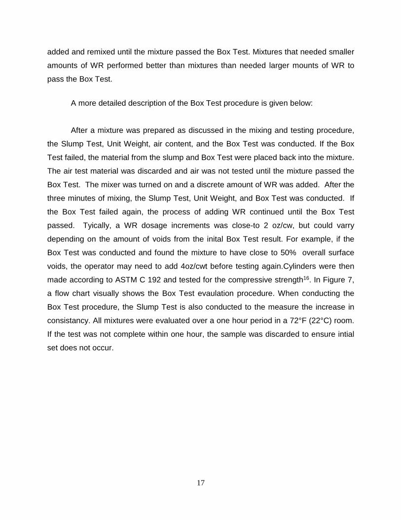
A more detailed description of the Box Test procedure is given below:
After a mixture was prepared as discussed in the mixing and testing procedure,
the Slump Test, Unit Weight, air content, and the Box Test was conducted. If the Box
Test failed, the material from the slump and Box Test were placed back into the mixture.
The air test material was discarded and air was not tested until the mixture passed the
Box Test. The mixer was turned on and a discrete amount of WR was added. After the
three minutes of mixing, the Slump Test, Unit Weight, and Box Test was conducted. If
the Box Test failed again, the process of adding WR continued until the Box Test
passed. Tyically, a WR dosage increments was close-to 2 oz/cw, but could varry
depending on the amount of voids from the inital Box Test result. For example, if the
Box Test was conducted and found the mixture to have close to 50% overall surface
voids, the operator may need to add 4oz/cwt before testing again.Cylinders were then
made according to ASTM C 192 and tested for the compressive strength16. In Figure 7,
a flow chart visually shows the Box Test evaulation procedure. When conducting the
Box Test procedure, the Slump Test is also conducted to the measure the increase in
consistancy. All mixtures were evaluated over a one hour period in a 72°F (22°C) room.
If the test was not complete within one hour, the sample was discarded to ensure intial
set does not occur.
17

Figure 7 - A flow chart of the Box Test procedure.
Results of Validating the Box Test A few variables need to be investigated into the Box Test should be validated.
Dosage method, repeatability of a measurement, comparison of multiple operators, and
multiple evaluation comparisons were investigated. Dosage method and repeatability of
measurement used a response ranking of 2 because mixtures responding poorly to
vibration can have sides or part of a sides collapse due to cohesive issues from lack of
paste being in voids. In contrast, a 1 ranking response was not chosen because the
surface voids could not be ranked if a mixture improved. Also, the Box Test was
conducted on two mixtures being used by a slip formed paver and the results were
evaluated using the Box Test ranking scale.
18

Effects of Sequential Dosage To investigate the impacts of the time and sequential dosage of the test
procedure, a series of nine replicate tests were completed where a single dosage of WR
was added proceeding the resting period in final 3 minutes instead of the sequential
dosages. As shown in Table 6, nine different mixtures were tested.
Table 6– Comparison of single and multiple dosages.
Mix WR (oz/cwt) Multiple Dosage Single Dosage
Rank Slump(in) Rank Slump(in) 1 8.3 2 1.5 2 1.5 6 18.1 2 2 2 2 4 13.4 2 2 2 2 8 5.5 2 0.5 2 0.5 9 5.8 2 1.25 2 0.5
10 14.5 2 1.25 2 1.25 11 3.4 2 1 2 0.5 12 6.2 2 0.5 2 0.5 13 13.5 2 2 2 2
Repeatability of a Single Operator Replication The result for the repeatability of WR dosage for a single operator was compiled
in Table 7. Ten mixtures were blindly replicated to compare the fresh properties. For
each mixture, the WR dosage added was enough to recieve a 2 ranking. The WR
dosage statistics are also listed. For each mixture, the maxium difference is the highest
amount of WR minus the lowest amount of WR. The percent difference is the maximum
different divided by the average WR times 100
.
19

Table 7 - Single operator repeatability.
Mix
Original Box Test
Repeated Box Test WR Statistics*
WR* Slump WR* Slump Average* Max Difference*
% Difference
1 8.3 1.5 9.5 1.25 8.9 1.2 13.7 2 14.5 2 13.5 1.5 14.0 1.0 7.1 3 7.0 2 4.5 2 5.8 2.5 43.5 4 15 1.5 14.8 1.5 14.9 0.2 1.3 5 17.5 2 15.8 2 16.7 1.7 10.2 8 5.5 0.5 7.9 .5 6.7 2.4 35.8 9 5.8 1.25 6.9 1 6.4 1.1 17.3 10 14.5 1.25 15.2 1 14.9 0.7 4.7 11 7.3 0.5 6.2 0.5 6.8 1.1 16.3 12 3.8 1 3.4 0.5 3.6 0.4 11.1
Average 1.23 16.1 *note: units are oz/cwt
Comparison of Multiple Operators Shown in Table 8, another important comparison can be the WR variation
between operators. Each operator added enough WR for a mixture to have a two
ranking..
Table 8. Multiple operators comparison.
Operator
A B C WR Statistics
Mix WR* Slump (in)
WR*
Slump (in) WR*
Slump (in)
Avg. WR*
Max Diff.*
% Diff.
3 7 2 3.5 2 5.1 2 5.2 3.5 67.3 8 7.9 0.5 5.5 1 5.1 1 6.2 2.8 45.4 9 6.9 1 4.7 1.25 7.2 1.25 6.2 2.5 39.9 10 15.2 1 15.7 1 15.2 1 15.4 0.5 3.3 11 7.3 0.5 5.5 0.5 9.1 0.5 7.3 3.6 49.3
Avg. 2.6 41.0
*note: units are oz/cwt
20
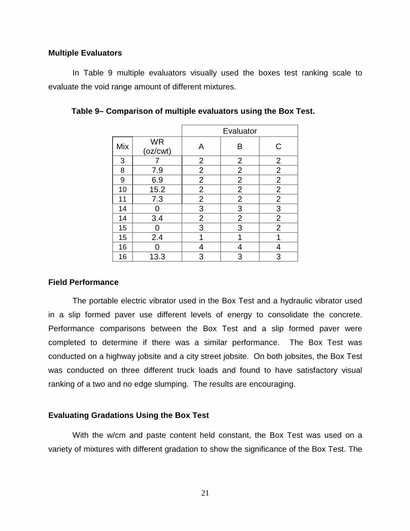
Multiple Evaluators In Table 9 multiple evaluators visually used the boxes test ranking scale to
evaluate the void range amount of different mixtures.
Table 9– Comparison of multiple evaluators using the Box Test.
Evaluator
Mix WR (oz/cwt) A B C
3 7 2 2 2 8 7.9 2 2 2 9 6.9 2 2 2 10 15.2 2 2 2 11 7.3 2 2 2 14 0 3 3 3 14 3.4 2 2 2 15 0 3 3 2 15 2.4 1 1 1 16 0 4 4 4 16 13.3 3 3 3
Field Performance The portable electric vibrator used in the Box Test and a hydraulic vibrator used
in a slip formed paver use different levels of energy to consolidate the concrete.
Performance comparisons between the Box Test and a slip formed paver were
completed to determine if there was a similar performance. The Box Test was
conducted on a highway jobsite and a city street jobsite. On both jobsites, the Box Test
was conducted on three different truck loads and found to have satisfactory visual
ranking of a two and no edge slumping. The results are encouraging.
Evaluating Gradations Using the Box Test With the w/cm and paste content held constant, the Box Test was used on a
variety of mixtures with different gradation to show the significance of the Box Test. The
21
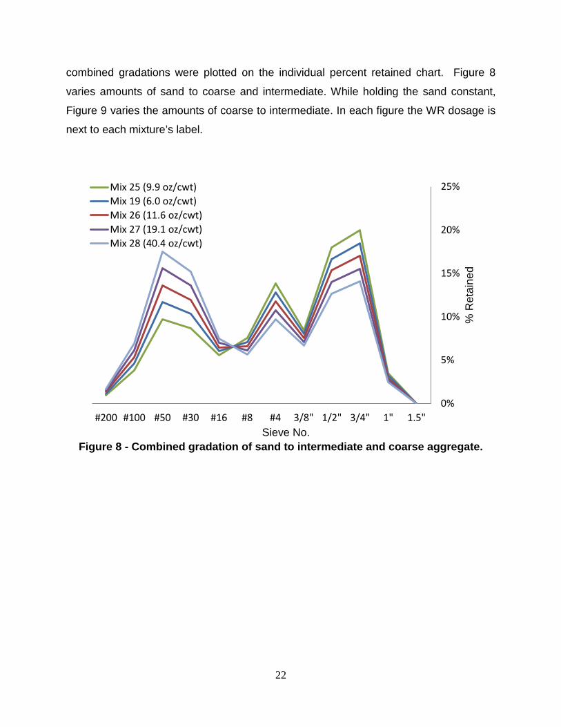
combined gradations were plotted on the individual percent retained chart. Figure 8
varies amounts of sand to coarse and intermediate. While holding the sand constant,
Figure 9 varies the amounts of coarse to intermediate. In each figure the WR dosage is
next to each mixture’s label.
Figure 8 - Combined gradation of sand to intermediate and coarse aggregate.
0%
5%
10%
15%
20%
25%
1.5"1"3/4"1/2"3/8"#4#8#16#30#50#100#200
% R
etai
ned
Mix 25 (9.9 oz/cwt)Mix 19 (6.0 oz/cwt)Mix 26 (11.6 oz/cwt)Mix 27 (19.1 oz/cwt)Mix 28 (40.4 oz/cwt)
Sieve No.
22

Figure 9 - Combined gradations of intermediate to coarse with constant sand
amounts.
Discussion The Box Test proved to be a useful tool to evaluate the response of the concrete
to vibration and simultaneously holding an edge. It’s important to note, none of the
mixtures used in this report had edge slumping issues. It seems that the visual ranking
scale ranges were good indications of how well the concrete responded to vibration.
Validations were conducted to determine how different variables impacted the surface
voids of the Box Test. Dosage method, repeatability of a measurement, and
comparison of multiple operators were the primary variables investigated and are
discussed in the proceeding sections. Also, it should be noted in all of these results, a
consistent slump measurement did not corresponded to a passing Box Test value. This
will be discussed in more detail later, but it’s a significant observation that is prevalent in
all results.
0%
5%
10%
15%
20%
25%
1.5"1"3/4"1/2"3/8"#4#8#16#30#50#100#200
% R
etai
ned
Mix 17 (13.3 oz/cwt)Mix 18 (12.7 oz/cwt)Mix 19 (6.0 oz/cwt)Mix 20 (4.3 oz/cwt)Mix 21 (6.3 oz/cwt)Mix 22 (3.9 oz/cwt)Mix 23 (2.9 oz/cwt)Mix 24 (11.9 oz/cwt)
Sieve No.
23

Effects of Sequential Dosage The comparison of the results on single and multiple dosages is shown in Table
6. Nine different mixtures were investigated to compare the response difference in
multiple and single dosages. Neither the Box Test nor the Slump Test was affected
whether a single or multiple dosage of WR was used.Each of the multiple and single
dosage mixtures had similar fresh properties and similar amounts of surface voids.
Repeatability of a Single Operator Replication As shown in Table 7, ten different mixtures were blindly replicated by a single
operator. From those mixtures it was found that the largest difference in WR to pass the
boxt test was 2.5 oz/cwt with an average difference of 1.2 oz/cwt. This low repeatability
suggests that the Box Test can be repeated accurately by a single user.
Comparison of Multiple Operators The repeatability of multiple operators can be shown in Table 8. The maximum
difference in WR dosage was 3.6 oz/cwt with an average value of 2.6 oz/cwt. These
values are higher than what was obtained from a single operator. This is expected
because there is some variance in replicating the same concrete mixture, subjectivity in
the dosage of WR, and the visual ranking. However, these values are not extreme and
still provide a useful comparison method between mixtures and their response to
vibration. The slump of each replicated mixture varied by 0.5” or less
.
Multiple Evaluators
24

In Table 9 multiple evaluators were provided a surface to evaluate and
independently visually rank the surface. Only one out of 11 evaluations had a different
visual ranking. This suggests the visual ranking between users is quite consistent.
Applying the Box Test Both Figure 8 and 9 use the WR dosage from the Box Test to compare the
performance of aggregate gradations with a fixed paste content. The gradations
requiring a higher dosage of WR are less desirable than a gradation requiring a lower
WR dosage. It is interesting to note that in both figures, a range of gradations required a
low amount of WR and would expected to perform well. Gradations outside of this zone
seemed to require significantly higher amounts of WR with only small changes in
gradation. While the amount of coarse and intermediate varied largely with only little
differences in WR dosage, a change in the amount of sand affected the workability of
the mixture. This data is quite useful as these comparisons were not possible with
previous testing methods.
Slump and Box Test Measurement When a mixture passed the Box Test, the slump value was within a typical range
for a concrete pavement mixture (ranging between 0” to 2”). It should be noted that the
slump tests were consistent for all repeated mixtures, but not a single slump value
seemed to be fixed with a passing performance in the Box Test. This is a critical
observation that supports this idea that the Slump Test does not provide a consistent
measuring tool for low slump concrete and suggests the Box Test and the Slump Test
are measuring two different phenomena.
Improvements to the Box Test
25

While the Box Test seems to be a very useful test to evaluate the suitability of a
mixture for a slip formed pavement, it seems improvements can be made. The primary
variability of the test comes from the dosage of WR added by the operator. If a more
systematic WR dosage procedure was used then this may reduce the variability
between users. However, the variability of the test was still found to be within
acceptable ranges to make comparisons between mixtures. This is especially true for
single operators.
Although the visual ranking scale was found to have a low inconsistency, it could
still be improved if a systematic point count was used to quantify the amount of voids on
the surface. An image analysis technique or a simple transparent overlay could be
placed on the concrete and individual points are counted.
While the scope of work did not include a closer examination of different mixing and
consolidation procedures, it would be interesting to see. Until further work is completed,
an emphasis should be taken to match the procedures and equipment as close as
possible.
Practical Implications It is important to realize the Box Test was only designed to evaluate a mixture’s
response to vibration and not necessarily to correlate with the exact performance of a
slip formed paver. However as previously discussed, the field evaluations completed
with the Box Test showed a satisfactory comparison. One of the more valuable
attributes of the Box Test is the actual simplistic approach of the test for laboratory or
field usage. The equipment of the Box Test is inexpensive and commonly available to
those in the concrete industry. Conducting and evaluating a mixture using the Box Test
is quick and easy to perform and provide a useful way to compare data.
Conclusion
26

An outline for the Box Test procedure was given and the data was presented
about the variability of the test. The results show the Box Testis a useful and
repeatable tool to evaluating different mixtures for slip formed paving. The following
points were made in this work:
1. Results show that the Box Test is a useful and repeatable tool to evaluate
different mixtures for a slip formed paver.
2. A single dosage or multiple dosages of water reducer did not change results of
the Box Test or Slump Test.
3. The repeatability of a single operator adding WR dosage had the largest
difference of 2.5 oz/cwt with an average difference of 1.2 oz/cwt.
4. Multiple operators adding WR dosage had a maximum different of 3.6 oz/cwt with
an average value of 2.6 oz/cwt.
5. The visually ranking of multiple evaluators was shown to be very consistent.
6. The Box Test was able to show the gradation of a mixture influenced the
response to vibration. While the amount of coarse and intermediate largely varied
with only a slight difference in WR dosage, a minor change in the amount of sand
significantly affected the workability of the mixture.
7. While the Slump Test does not provide a consistent measuring tool for low slump
concrete, the Box Test can be a useful tool.
27

Chapter 3 - Use of a Concrete Mixer to Evaluate the Rheology of low Slump Concrete Mixtures
Introduction One of the most difficult and allusive areas in the concrete industry has been the
workability of concrete. Workability is defined, according to American Concrete Institute
(ACI), as a property of freshly mixed concrete or mortar that determines the ease with
which it can be mixed, placed, consolidated, and finished to a homogeneous condition.
The most common method to measure workability of concrete is by the Slump Test1.
However, a study comparing the Slump Test and workability of concrete by the National
Ready-Mixed Concrete Association (NRMCA) and the National Institute of Standards
and Technology (NIST) which proves that Slump Test is not a reliable method in terms
of concrete workability18. This study showed that concrete mixtures with the same slump
do not behave the same during placement. But the Slump Test is still used to describe
the workability of concrete because it measures and incorporates all workability
applications in a quick and simple manner.
It is important to note a large number of workability tests have been developed
over the years. For only certain applications, a few of these workability tests have
proven to be useful. However, a single workability test has not been proven to
effectively predict the workability of concrete at all ranges. Therefore, there is a need to
measure the workability of concrete using a single tool.
One approach to encompassing the workability ranges of concrete has been to
look at the rheology, which is the study of the flow of a liquid from external pressures.
Although rheology has been used as a useful tool in a number of fields of material
science, only recently has it been investigated in the concrete’s workability. This
chapter describes an attempt to use a common laboratory shear pan-mixer to measure
the rheological properties of concrete mixture. In order to do this, a computer system
with input and output control was installed on the pan-mixer. The computer system
28

allows the user to control the speed, torque, current, or voltage and monitor the other
three variables. A total of seven identical mixes were made during this project to
examine the potential for using this equipment to measure the rheology of low to high
flowable mixtures.
Experimental Methods
Material All the concrete mixtures described in this paper were prepared using a Type I
cement that meets the requirements of ASTM C 1507. Table 10 shows the oxide
analysis of the cement. A 20 % fly ash replacement and a water reducer (WR) were
used. According to ASTM C 4948 the water reducer was a lignosulfonate mid-range
WR and ASTM C 6189 classifies the fly ash as type C. Also used is a superplasticizer
that meets ASTM C101717 type I. A single Oklahoma crushed limestone and river sand
were used in this research. A sieve analysis for each of the aggregates was completed
in accordance with ASTM C 13610. Absorption and specific gravity of each aggregate
followed ASTM C 12711 for a coarse aggregate or ASTM C 12812 for a fine aggregate.
In Figure 10, the sieve analysis for each aggregate is shown.
Table 10 – The oxide analysis for the cement used in the study.
Chemical Test
Results
SiO2 Al2O3 Fe2O3 CaO MgO SO3 Na2O K2O
21.1% 4.7% 2.6% 62.1% 2.4% 3.2% 0.2% 0.3%
Bogue C3S C2S C3A C4AF
56.7% 17.8% 8.2% 7.8%
29

Figure 10 - Sieve analysis for each aggregate type.
30

Mixture Design Before comparing the flowability measurements of different mixtures, a single
mixture should be replicated multiple times to ensure the flowability measurements are
reliable and repeatable. A single mixture was design to have a low flowability and a
water reducer was added to increase the flowability. To measure the differences in
flowability, each of the mixtures used consistent mid or high range WR dosages. Since
the initial mixture required a low flowability, the paste content was 5 sacks (470lbs) with
a constant 0.45 w/cm and 20% fly ash replacement. Table 11 contains the batch
weights of the mixture designed used.
Table 11– The batch weight used.
Materials Weight(lbs./cy)
Cement 376
Fly ash 94
Coarse 1553
Intermediate 508
Fine 1280
Water 212
Mixing and Testing Procedure
Pan Mixer
To measure the rheology of the concrete, a pan mixer with a control and
monitoring system on a computer was used. A pan-mixer was used to allow a more
31

consistent flowability than a drum mixer. As shown in Figure 11 the pan-mixer uses two
different components, a bowl and a lid attached with blades to mix the material into
concrete. While using a rotational bowl to hold the material, the blades rotate in the
opposite direction of the bowl to mix. The control and monitoring system allows voltage,
current, torque, and speed to be measured and controlled. For this research, the rpm of
the mixer were controlled and the voltage, current, and torque were monitored. A low
flowability mixture should require more torque, voltage, and current to maintain a
constant speed than a higher flowable mixture.
Figure 11- The different components of the pan-mixer.
Mixing procedure
Aggregates are collected from outside storage piles, and brought into a
temperature-controlled laboratory room at 72°F (22°C) for at least 24-hours before
mixing. Aggregates were placed in a mixing drum and spun and a representative
sample was taken for a moisture correction.
32

Starting the premixing stage, aggregates were loaded into the mixer along with
approximately two-thirds of the mixing water. This combination was mixed for three
minutes to allow the aggregates to approach the saturated surface dry (SSD) condition
and ensure that the aggregates were evenly distributed. Next, the cement, fly ash, and
the remaining water was added and mixed for three minutes. The resulting mixture
rested for two minutes while the sides of the mixing bowl were scraped. After the rest
period, the mixer was turned on and mixed for three minutes. The entire premixing
stage kept a constant the pan-mixer speed of 1400 rpm.
Using the Pan-Mixer to Measure the Rheology of the Concrete After the premixing stage was complete, the slump of the mixture was tested.
Then a mixture’s flowability was measured using the amount of torque, current, and
voltage used to move the mixture at different speeds intervals. Three interval speeds of
1400 rpm, 942 rpm, and 462 rpm with 300 seconds per a speed interval were used to
collect flowability measurements. To measure the changes in a mixture’s flowability, a
water reducer was added and remixed for three minutes at 1400 rpm. Again, the slump
and flowability measurements were taken. Finally, a second water reducer dosage was
added and remixed for three minutes at 1400 rpm. The slump and flowability
measurements were taken. For a graphical representation of this procedure is shown in
Figure 12.
33

Figure 12 –The pan mixer speed intervals with increasing amounts of WR.
Results
A total of seven mixtures were made in this project. In four mixtures used a mid-
range water reducer and three mixtures used a high range water reducer. The dosage
amounts of a mid-range or high range were consistently close in each dosage stage.
For the first stage using no WR, the slump ranged from 1” to 1.5”. For the mid-range
WR, the first dosage had a slump of 2” to 2.5” and the second dosage had a 3” to 4”
slump. For the high range WR, the first dosage had a slump of 5 to 6.5” and a second
dosage slump of 7” to 9”.
Each of the figures below has a line with the standard deviation for the torque. Figure 13
compares the workability change of a mixture with the use of a WR. It graphs the
changes in speed to the torque percent of the pan-mixer. Figure 14 shows different
torque with respect to three different rpm that was used during the initial mixing. The
torque and speed of the first dosage of a WR is shown in Figure 15. And the second
dosage of WR is shown in Figure 16.
34

Figure 13 –Changes in torque using a WR.
Figure 14– Measuring torque at three interval speeds with no WR.
25
30
35
40
45
50
55
60
65
70
400 600 800 1000 1200 1400
Torq
ue %
Speed
No WR Admixture Dosage
21
26
31
36
41
46
51
56
61
66
430 630 830 1030 1230 1430
Torq
ue %
Speed
Mix-1 Mix-4
Mix-6 (Superplasticizer-dosage) Mix-7 (Superplasticizer-dosage)
Mix-5 (Superplasticizer-dosage)
35

Figure 15 –First WR dosage measuring torque at the interval speeds.
Figure 16- Second WR dosage measuring torque at the interval speeds.
21
26
31
36
41
46
51
56
61
66
430 630 830 1030 1230 1430
Torq
ue %
Speed
Mix-1 Mix-2Mix-3 Mix-4Mix-5 (Superplasticizer-dosage) Mix-6 (Superplasticizer-dosage)Mix-7 (Superplasticizer-dosage)
21
26
31
36
41
46
51
56
61
66
430 630 830 1030 1230 1430
Torq
ue %
Speed
Mix-1 Mix-2 Mix-3 Mix-4 Mix-6 (Superplasticizer-dosage) Mix-7 (Superplasticizer-dosage)
36

Discussion:
The rheological characteristics of the mixture were attempted to be characterized
using the torque, current, voltage and speed from the pan mixer. The same mixture
design was replicated seven different times and the torque was measured at similar
slump values.
In Figure 14, the slumps of the different mixtures were all very close, but they
didn’t have similar torque values. Since the seven different mixtures had the same batch
weights and similar slumps, this shows the pan-mixer is not very repeatable.
Looking at Figures 13, 14 and 15, the WR reduced the amount of torque and
increased the slump. This follows the thought process as the slump increased the
mixer requires less energy or torque to force the blades through the concrete. However,
Figure 15 and 16 has a significant difference in slump, but not a large change in torque.
This could suggest the pan-mixer requires a certain torque to move the different
components. A more sensitive pan-mixer might have a better chance of measuring the
flow of a low slump mixture.
Conclusion The following conclusions were formed:
• The pan-mixer was unable to consistently measure the torque percent of the
concrete with similar slumps.
• However, the pan-mixer could consistently measure if a mixture had a low slump,
or a mid to high slump.
• A mid-range slump could not be differentiated from a high valued slump.
• A higher sensitive pan-mixer might be able to measure the flow of low slump
mixtures.
37

CHAPTER 4 – INVESTIGATION OF AGGREGATE CHARACTRISTICS FOR CONCRETE WITH THE AIMS II
Introduction
About two-thirds of the total volume of concrete is aggregates. However, the
workability impacts of aggregate characteristics and gradation on concrete have been
largely neglected. While gradation has been classified according to ASTM C33, the
aggregate characteristics do not have definite requirements to be used in concrete.
Numerous claims have been made about different aggregate characteristics
impacting the workability concrete. The majority of the aggregate claims revolve around
the angularity, texture, and shape variation influences the workability of the concrete.
The mechanisms of packing and frictional resistance have been the two leading
believes behind the workability effects on aggregates. Typically the packing mechanism
of aggregates is explained using a dry packing model. It is an approach to determine
the ability of an aggregate’s gradation, shape, and angularity to fill a volume by
measuring the amount of voids. For example, a very flat and elongated shape will take
up less space than a cubical or spherical shape. However, the frictional resistance
focuses on the different aggregate variables that impede the flow of a concrete mixture.
These aggregate variables contributing to frictional resistance include the shape,
angularity, and gradation of the aggregate. For example, a river rock with low angular,
well-shaped, and low textured aggregate will have less frictional resistances causing a
better workability than a crushed limestone with high angularity, high texture, and
extreme flatness and elongation. Therefore using a river rock should require less paste
to achieve a certain workability than a crushed limestone and will be more cost
effectiveness of the concrete. Unfortunately, none known research has been conducted
on these mechanisms for normal concrete mixtures.
38

Other aggregate impacts besides the workability can impact the concrete. For
concrete pavements with transverse cracking, faulting of joints and cracks, punch outs,
and spalling at joints and cracks have been attributed to coarse aggregate particle
shape and angularity19. This mechanism has been contributed to the bond strength
between cement paste and the aggregate’s shape, angularity, and surface texture20. In
other words, the bond strength increases as aggregates become rougher and more
angular21. Weak bonding of aggregates in concrete pavements has been attributed to
longitudinal and transverse cracking, joint cracks, spalling, and punch outs22
A necessitate into understanding the workability of concrete and other factors
creating problems in concrete is to classify aggregate characteristic. A basic
classification has been to measure angularity, texture, and different variations of shape.
In the past, only a human eye with some basic measuring tool could only classify the
aggregate characteristics. However recently, computer imaging systems are starting to
be incorporated into classifying aggregate characteristics. One of the more advanced
systems this research will be using is the AIMS II. The main goal of this chapter is to
evaluate various aggregate characteristics using the Aggregate Imaging Measurement
System 2 or AIMSII.
Materials
Eleven coarse aggregate and three fine aggregate were analyzed using the
AIMS II. As shown in Table 12, the aggregates types used are: nine limestones, one
sandstone, two river gravels, one manufactured sand, and two river sands. The majority
of the aggregate sources are from the state of Oklahoma with the exception of Lamar
from Colorado and Cleburne and Wright from Texas. The aggregate sources are
commonly used in concrete. Other than Cleburne and Wright, all of the aggregates
studied are approved by Oklahoma Department of Transportation. A sieve analysis of
each aggregate type can be shown in Figure 17.
39

Table 12 – Source Type and name of each aggregate investigated.
Type Source Name
3/4" Nominal Max Coarse
Limestone Richard Spur Limestone Drumright Limestone Pryor Limestone Okay Limestone Coleman Limestone North Troy Limestone Davis Limestone Hartshorne Sandstone Sawyer Limestone Cooperton
River Gravel Cleburne River Gravel Lamar
Sand River Arkhola River Dover
Manufactured Wright
40

Figure 17- Sieve analysis of each aggregate being analyzed by the AIMS II.
0
10
20
30
40
50
60
70
80
90
100
1"3/4"1/2"3/8"#4#8#16#30#50#100#200
Perc
enta
ge P
assi
ng(%
)
Sieve NumberRichard Spur Drumright Pryor Okay ColemanNorth Troy Davis Hartshorne Sawyer CoopertonCleburne Lamar Arkhola Dover Wright
41
Testing Procedure using the AIMS II
According to past work, the AIMS II has been proved to be relatively good
repeatability, reproducibility, and sensitivity23. The development of the method can be
found by Masad24. The specific objective of this project was to quantify aggregate
characteristics from different quarries and sand sources. Each aggregate source was
sieved into individual sieve sizes, washed, and analyzed using the automated AIMS II
system. The AIMS II measures coarse and fine aggregate differently. Any sieve size at
or above 4.75mm (no.4) will be measured for angularity, sphericity, surface texture, 3-
dimensional shape and flat and elongated. However, the aggregate characteristics
differ in that anything below the 4.75mm (no.4) will only have angularity and a form 2D
measurement.
Coarse Aggregate Specific Measurements
To examine coarse aggregate the AIMSII investigates aggregates that are
washed and separated by sieve size retained on a 4.75-mm (No. 4) and larger. The
aggregate sample is placed on a tray that is rotated past three different lighting levels.
These include a back light, top light, and lighting to measure the texture of the
aggregates. The tray rotates, positioning the aggregates in the back lighting and under
the camera for imaging. Each particle silhouette is captured and the centroid of the
outline determined. A second tray scan is performed using top lighting for the height
measurement. A third scan captures the texture of the sample. These three allow
analysis of coarse aggregates shape, angularity, texture, and particle dimensions. From
these measurements the system provides the following values for each aggregate:
• Coarse Aggregate Angularity (AIMS Angularity Index ranges from 1 to 10000)
• Coarse Aggregate Texture (AIMS Texture Index ranges from 0 to 1000)
• Coarse Aggregate Sphericity (AIMS Sphericity Index ranges from 0 to 1)
• Coarse Aggregate Flat and Elongated
42

These measurements will be discussed in further detail in the coming sections.
However, more details on the system design and how it operates can be found in
reference24.
Gradient Angularity
Gradient Angularity applies to both fine and coarse aggregate sizes and
describes variations at the edge of the particle that impact the overall shape. The
gradient angularity quantifies changes along a particle boundary with higher gradient
values indicating a more angular shape. Gradient angularity has a relative scale of 0 to
10000 with a perfect circle having a small non-zero value. It is analyzed by quantifying
the change in the gradient on a particle boundary25 and is related to the sharpness of
the corners of 2-dimensional images of aggregate particles. Shown in Figure 18 below,
the gradient method starts by calculating the inclination of gradient vectors on particle
boundary points from the x-axis (horizontal axis in an image). The average change in
the inclination of the gradient vectors is taken as an indication of angularity. Figure 19
shows the AIMS II measurement for angularity.
Figure 18 - Gradient Vector for Smooth vs. Angular Particle25.
43

Figure19 - Fine and Coarse Aggregate Angularity Ranges26. Texture
Texture describes the relative smoothness or roughness of aggregate particles’
surfaces. AIMS Texture applies to coarse aggregate sizes only and describes surface
micro-texture, features less than approximately 0.5 mm in size which are too small to
affect the overall shape. Texture has a relative scale of 0 to 1000 with a smooth
polished surface approaching a value of 0. The AIMS Texture analysis uses the wavelet
method to quantify texture27,28,29. The wavelet analysis gives the texture details in the
horizontal, vertical, and diagonal directions in three separate images. The texture index
at a given decomposition level is the arithmetic mean of the squared values of the
wavelet coefficients for all three directions. The texture index is expressed
mathematically as follows:
( )23
,1 1
1 .3
N
i ji j
TextureIndex D x yN = =
= ∑∑ (3.1)
where n refers to the decomposition level, N denotes the total number of coefficients in
a detailed image of texture; i takes values 1, 2, or 3, for the three detailed images of
texture; j is the wavelet coefficient index; and (x, y) is the location of the coefficients in
44

the transformed domain. Fletcher29 found that texture can be least affected by color or
dust particles on the surface of the particles by using a certain level of low resolution
and detailed images. In Figure 20, a texture scaled was developed with images and a
range of numbers.
Figure 20 - Coarse Aggregate Texture Range
Sphericity
Using sphericity the form is quantified in three dimensions. The three dimensions
of the particle the longest dimension (dL), the intermediate dimension (dI), and the
shortest dimension (ds) are used in equation 3.2 for sphericity and shape factor.
3 2
.s I
L
d dSphericityd
= (3.2)
The two major and minor axes are analyzed from the black and white images
(Eigenvector analysis) while the depth of the particle is measured by auto focusing of
themicroscope29.
45

Figure 21 - Cluster Classification Charts for Different Aggregate Properties23. Flat & Elongated, Flat or Elongated
The flat and elongated test measures the percentage of particles above a
specified dimension ratio, rather than distribution of relative sizes27.Flat & Elongated
represents the ratio of the particle dimensions as described in Equations below:
Flatness Ratio: Flatness = s
I
dd
(3.3)
Elongation Ratio: Elongation = I
L
dd
(3.4)
Flat & Elongated Value: L/S = L
s
dd
(3.5)
where: dS = particle thickness (shortest dimension)
dI = particle width (intermediate dimension)
dL = particle length (longest dimension)
Flat or elongated is the ratio of the particle dimensions described in Equation below:
Flat or Elongated Value (ForE): IdS
or L
I
dd
≥ Ratio (i.e.: 1, 2, 3…) (3.6)
Coarse Aggregate Angularity Texture Value (CAAT)
Coarse Aggregate Angularity Texture (CAAT) is a combined angularity texture
value described in Equation 3.7 below:
46

10 0.5CAAT XTX XGA= + (3.7)
Fine Aggregate Specific Measurements To examine fine aggregate the AIMSII investigates aggregates that are washed
and separated by sieve size passed on a 4.75-mm (No. 4) down to retained by
0.075mm (No. 200). The aggregate sample of approximately 50 grams for each size is
spread uniformly around the tray trough. Only one scan of the tray is needed, and
backlighting is used in this analysis for the larger fine sizes. The tray rotates and images
are captured until the desired particle count (150 in this project) is reached. Images are
evaluated to remove touching particles from the analysis. The system provides the
following measures for fine aggregate particles.
• Fine Aggregate Angularity (AIMS Angularity Index ranges from 1 to 10000)
• Fine Aggregate Form 2D (AIMS Form 2D Index ranges from 0 to 20)
Form 2D
AIMS Form 2D applies to fine aggregate sizes only and quantifies the relative
form from 2-dimensional images of aggregate particles. The form index Form 2D is
expressed by Equation below. Form 2D has a relative scale of 0 to 20. A perfect circle
has a Form 2D value of zero.
360
02 R RForm D
R
θ θθ θ θ
θ θ
= −∆+∆
=
−= ∑
Where:Rθ is the radius of the particle at an angle of θ
∆θ is the incremental difference in the angle
(3.8)
47

Figure 22 - Fine aggregate form 2D ranges.
Results Each aggregate source was analyzed using the AIMS II. After analyzing each
sieve size, similar to what currently is being done for aggregate gradation, each of the
shape characteristics from each sieve size is presented by cumulative distribution
instead of single average value for each property. Dealing with the distribution of
aggregate characteristics rather than average indices is advantageous for the
development of reliable specifications given the high variability in shape characteristics
within an aggregate sample28. The next step is to statistically analyze the data and
assign or identify aggregate groups based on distribution of data acquired. Analyzing
the data based on their distribution suggests much more reliable approach to data
interpretation28. (Note: characteristics acquire using AIMS has been compared to,
laboratory performance tests and field test28).
48

Figure 23 shows texture index vs. aggregate percent frequency. Figure 24, which
is angularity index vs. aggregate percent frequency, present the angularity of the
aggregates. Figure 25 has the sphericity results of each coarse aggregate. Figure 26
the X-axis shows flat and elongated factor which comes from Eq. 3.6. In Figure 26 the
X-axis shows flat and elongated factor which comes from Eq. 3.6. Figure 27 and 28
show the fine aggregate characteristics of angularity and form 2D, respectively.
Figure 23 – AIMS measuring texture index of coarse aggregate.
49

Figure 24- AIMS measuring angularity of coarse aggregate.
Figure 25 –AIMS measuring the sphericity index of coarse aggregate.
50

Figure 26 - AIMS measuring flat and elongated of coarse aggregate
Figure 27 - AIMS measuring the angularity of fine aggregates.
51

Figure 28 – AIMS measuring the form 2D index of fine aggregate.
Discussion
Texture Figure 23 shows texture index vs. aggregate percent frequency. As one can see,
coarse aggregate image analysis results show that North Troy, Cleburne, and Lamar
have relatively low texture in comparing to other aggregates. Likewise, these 11
aggregates can be divided into three zones with low, moderate, and high texture.
Aggregate with moderate texture are Sawyer, Hartshorne, and Pryor. On the other
hand, because of the fact that aggregates from a quarry come with a wide range of
texture rather than a single specific number that can be assigned to the aggregates,
some of these aggregate such as Richard Spur, Davis, Drum Wright, Coleman, Okay,
and Cooperton are located in the graph where their texture range vary from moderate
52
all way through high and extreme zone. So in order to separate the aggregates from
one another it was preferred to use peak of each line which is an indication of where
most of particles fall into. According to this fact, Cooperton is an aggregate with high
and extreme texture while Richard Spur, Davis, Drum Wright, and Coleman are
considered to have high texture. As for Okay, despite of having higher texture than
other aggregates that fell into high texture zone, it is still identified as high texture.
Angularity
Figure 24, which is angularity index vs. aggregate percent frequency, present the
angularity of the aggregates. The results show that Cleburne and Lamar have the least
angularity among all the aggregates which is in accordance to what we expected
considering they are both river rock. According to the fact discussed in the previous
section, all the other aggregates, despite of having minor differences in their peak point
are all within the moderate zone.
Sphericity In Figure 25 as one moves toward the right side, aggregates become more and more
spherical. The graph shows that all the aggregates from different quarry have sphericity
range of 0.4 (low sphericity) to 1 (high spherical). The only difference is the percent that
falls under each category. According to this fact, Okay has the least amount of spherical
particle among all the other aggregates and it follows by Richard spur, Pryor, and
Coleman. Lamar and Davis on the other hand; have the most amount of spherical
particle. All the other aggregates have relatively the same amount of spherical particle.
Flat & Elongated
In Figure 26 the X-axis shows flat and elongated factor which comes from
equation 3.6. In this graph as one moves toward the right side particles become more
and more flat and elongated. As it is shown in the graph, Okay is one aggregate that
53

stands out among all the others for being extremely flat and elongated. Coleman and
Richard spur contain more flat and elongated particles after Okay. The rest of the
aggregates have relatively close amount of flat and elongated particle.
Angularity of Fine Aggregate
Figure 27 shows that Dover and Arkhola have relatively the same amount of
angularity and they fall into category of moderate range. Wright on the other hand, has
a wider range of angularity that varies from moderate range to high. Wright is
manufactured sand and it was expected to have a higher angularity than natural sand.
According to the following graph it is considered to have moderate and high angularity.
Form 2D
As it was explained in previous part a perfect circle has a Form 2D value of zero.
Therefore, as one moves forward to the right of this graph particles become less and
less circular. Figure 28 shows a large amount of Dover and Arkhola particles belong to
low zone which is a circular range. Wright on the other hand, is manufactured sand and
it contains more moderate and high range particles. This indicates that Wright particles
are less circular comparing to Dover and Arkhola which are natural sand.
Conclusion
Eleven coarse aggregates were characterized using AIMS II. The study showed
that texture varies considerably among aggregate samples. North Troy, Cleburne, and
Lamar had relatively low texture in comparing to other. Aggregates with moderate
texture are Sawyer, Hartshorne, and Pryor. Cooperton is an aggregate with high and
extreme texture while Richard Spur, Davis, Drumwright, Okay, and Coleman are
considered to have high texture.
54

Angularity data shows Cleburne and Lamar have the least angularity among all the
aggregates which is in accordance to what we expected considering they are both river
rock. All the other aggregates, despite of having minor differences fall within the
moderate zone. As for sphericity of aggregates, Okay has the least amount of spherical
particle among all the other aggregates and it follows by Richard spur, Pryor, and
Coleman. Lamar and Davis on the other hand; have the most amount of spherical
particle. All the other aggregates have relatively the same amount of spherical particle.
Flat and elongated is another characteristics of aggregates that was measured using
this method. According to Fig. 9 Okay is one aggregate that stands out among all the
others for being extremely flat and elongated. Coleman and Richard spur contain more
flat and elongated particles after Okay. The rest of the aggregates have relatively the
same amount of flat and elongated particle.
Angularity and form 2D are two characteristics of fine aggregates that was
measured using AIMS II. Fine aggregates that were tested through this method are
Dover and Arkhola as an example of natural sand and Wright which is manufactured
sand. Data shows that Dover and Arkhola have relatively the same amount of angularity
and they fell into the category of aggregate with moderate angularity. Wright on the
other hand, has a wider range of angularity that varies from moderate range to high.
When it comes to form2D, date showed that a large amount of Dover and Arkhola
particles belong to low zone which is a circular range. Wright on the other hand, is
manufactured sand and it contains more moderate and high range particles. This
indicates that Wright particles are less circular comparing to Dover and Arkhola which
are natural sand.
55

CHAPTER 5 – CONCLUSION Two different methods to evaluate the performance of a low flowable mixture
were tested. Also, different aggregate characteristics were evaluated using the AIMS II.
The following conclusions were made with this research:
• A workability test was developed to evaluate a low flowable mixture’s response to
vibration called the Box Test.
• The rheology of low slump was attempted to be measured using a pan-mixer, but
a consistent measurement was not found.
• Different aggregate characteristics were evaluated from many different sources,
especially aggregate sources approved for the Oklahoma Department of
Transportation.
56

CHAPTER 6 – FUTURE WORK While obtaining these results for aggregates in Oklahoma is a great
accomplishment, more work is needed to understand what these measurements mean.
This includes the relationship between aggregate shape characteristics from AIMS II,
concrete mixture proportions, and performance. This should be done for all major
applications of concrete with different levels of workability.
57

REFERENCES 1. ASTM C 143/C 143M-03, Standard Test Method for Slump of Hydraulic Cement
Concrete (ASTM, West Conshohocken, Pennsylvania 2012).
2. ASTM C 1621-09, Standard Test Method for Passing Ability of Self- Consolidating
Concrete (ASTM, West Conshohocken, Pennsylvania 2009).
3. ASTM C 1611-09, Standard Test Method for Slump Flow of Self-Consolidating
Concrete (ASTM, West Conshohocken, Pennsylvania 2009).
4. Shilstone, James M., A Hard Look at Concrete, Civil Engineering, January 1989,
pages 47-49.
5. Powers, T.C, The Properties of Fresh Concrete, John Wiley & Sons, Inc. New York.
1968
6. Wong, S., Alexender, M., Haskins, R, Pool, T., Maloone, P., and Wakeley, L.
Portland-Cement concrete Rheology and Workability: Final Report. FHWA-RD-00-
025. McLean, VA: United States Federal Highway Administration (2001)
7. ASTM C 150-12, Standard Specification for Portland Cement (ASTM, West
Conshohocken, Pennsylvania 2012).
8. ASTM C 494-05, Standard Specification for Chemical Admixtures for Concrete
(ASTM, West Conshohocken, Pennsylvania 2005).
9. ASTM C 618-12a, Standard Specification for Coal Fly Ash and Raw or Calcined
Natural Pozzolan for Use in Concrete (ASTM, West Conshohocken, Pennsylvania
2012).
10. ASTM C 136-06, Standard Test Method for Sieve Analysis of Fine and Coarse
Aggregates (ASTM, West Conshohocken, Pennsylvania 2006).
11. ASTM C 127-12, Standard Test Method for Density, Relative Density (Specific
Gravity), and Absorption of Coarse Aggregate (ASTM, West Conshohocken,
Pennsylvania 2012).
12. ASTM C 128-12, Standard Test Method for Density, Relative Density (Specific
Gravity), and Absorption of Fine Aggregate (ASTM, West Conshohocken,
Pennsylvania 2012).
58

13. ASTM C 231-04, Standard Test Method for Air Content of Freshly Mixed Concrete
by the Pressure Method (ASTM, West Conshohocken, Pennsylvania 2004).
14. ASTM C 138-13, Standard Test Method for Unit Weight, Yield, and Air Content
(Gravimetric) of Concrete (ASTM, West Conshohocken, Pennsylvania 2013).
15. ASTM C 192-12, Standard Practice for Making and Curing Concrete Test
Specimens in the Laboratory (ASTM, West Conshohocken, Pennsylvania 2012).
16. ASTM C 39-04, Standard Test Method for Compressive Strength of Cylindrical
Concrete Specimens (ASTM, West Conshohocken, Pennsylvania 2004).
17. ASTM C 143/C 143M-12, Standard Test Method for Slump of Hydraulic-Cement
Concrete (ASTM, West Conshohocken, Pennsylvania 2012).
18. Ferraris, C.F., Lobo, C. (1988) Processing of HPC, Concr. Int. 20 (4) pp. 61 -64.
19. Meininger, R. C. (1998). “Aggregate test related to performance of portland cement
concrete pavement.” Final Report, National Cooperative Highway Research
Program Project 4-20A. Transportation Research Board, National Research Council,
Washington, D.C.
20. Mindness, S., and Young, J. F., (1981) Concrete. Prentice Hall Inc., Englewood
Cliffs, New Jersey.
21. Kosmatka, S. H., Kerkhoff, B., and Panarese, W. C. (2002). “Design and control
ofconcrete mixtures.” 14th Ed., Portland Cement Association, Skokie, Ill.
22. Folliard, K. J. (1999). “Aggregate tests related to performance of portland
cementconcrete pavements.” Phase 1 Interim Report, Project 4-20B, National
Cooperative Highway Research Program, Austin, Texas.
23. Eyad Masad. (2005). “A Progress Repoort Submitted to the Pavement Engineering
Program of the Federal Hightway Administration.” Department of Civil Engineering,
Texas Transportation Institute.
24. Masad, E. The Development of A Computer Controlled Image Analysis System for
Measuring Aggregate Shape Properties. NCHRP-IDEA Project 77 Final Report,
Transportation Research Board,Washington, D.C., 2003
59

25. Chandan, C., Sivakumar, K., Fletcher, T., and Masad, E. (2004). “Geometry Analysis
of Aggregate Particles using Imaging Techniques.” Journal of Computing in Civil
Engineering, ASCE, 18 (1), 75-82.
26. Krumbein, W. C. (1941). “Measurement and Geological Significance of Shape
andRoundness of Sedimentary Particles.” Journal of Sedimentary Petrology, 11(2),
64-72.
27. Fletcher, T., Chandan, C., Masad, E., and Siva Kumar, K. (2002). “Measurements of
aggregate texture and its influence on HMA permanent deformation.” Journal
ofTesting and Evaluation, American Society for Testing and Materials, ASTM,30(6),
524-531
28. Al-Rousan, T.M. (2004). “Characterization of Aggregate Shape Properties using
aComputer Automated System.” PhD Dissertation, Dept. of Civil Engineering, Texas
A&M University, College Station, Texas.
29. Fletcher, T., Chandan, C., Masad, E., and Siva Kumar, K. (2003). “Aggregate
Imaging System (AIMS) for characterizing the shape of fine and coarse aggregates.”
Transportation Research Record 1832, Transportation Research Board, Washington
D.C., 67-77.
60
Related Documents