Journal of Mechanical Science and Technology 29 (2) (2015) 835~843 www.springerlink.com/content/1738-494x DOI 10.1007/s12206-015-0147-5 Economic assessment of greenhouse gas reduction through low-grade waste heat recovery using organic Rankine cycle (ORC) † Muhammad Imran 1,2 , Byung-Sik Park 1,2,* , Hyouck-Ju Kim 1,2 , Dong-Hyun Lee 2 and Muhammad Usman 1,2 1 Energy System Engineering, University of Science & Technology, Daejeon, 305–350, Korea 2 Energy Network Team, Korea Institute of Energy Research, Daejeon, 305–343, Korea (Manuscript Received May 25, 2014; Revised September 16, 2014; Accepted October 25, 2014) ---------------------------------------------------------------------------------------------------------------------------------------------------------------------------------------------------------------------------------------------------------------------------------------------- Abstract Low-grade waste heat recovery technologies reduce the environmental impact of fossil fuels and improve overall efficiency. This pa- per presents the economic assessment of greenhouse gas (GHG) reduction through waste heat recovery using organic Rankine cycle (ORC). The ORC engine is one of the mature low temperature heat engines. The low boiling temperature of organic working fluid en- ables ORC to recover low-temperature waste heat. The recovered waste heat is utilized to produce electricity and hot water. The GHG emissions for equivalent power and hot water from three fossil fuels—coal, natural gas, and diesel oil—are estimated using the fuel analysis approach and corresponding emission factors. The relative decrease in GHG emission is calculated using fossil fuels as the base case. The total cost of the ORC system is used to analyze the GHG reduction cost for each of the considered fossil fuels. A sensitivity analysis is also conducted to investigate the effect of the key parameter of the ORC system on the cost of GHG reduction. Throughout the 20-year life cycle of the ORC plant, the GHG reduction cost for R245fa is 0.02 $/kg to 0.04 $/kg and that for pentane is 0.04 $/kg to 0.05 $/kg. The working fluid, evaporation pressure, and pinch point temperature difference considerably affect the GHG emission. Keywords: Economic assessment; Greenhouse gas; Organic rankine cycle; Waste heat recovery ---------------------------------------------------------------------------------------------------------------------------------------------------------------------------------------------------------------------------------------------------------------------------------------------- 1. Introduction The leftover heat produced by combustion or any chemical or thermal process is known as waste heat because it is usually exhausted directly to the environment. Waste heat has not only the highest value of exergy but also a high concentration of pollutants, including carbon dioxide (CO 2 ), nitrogen oxides (NO X ), and sulfur oxides (SO X ), which are responsible for global warming [1]. Electricity, heat generation, and transpor- tation account for two-thirds of the global CO 2 emission [2]. The large concentrations of CO 2 in these two sectors can be attributed to the usage of fossil fuels coal, natural gas, and petroleum. The CO 2 emission from each sector is shown in Fig. 1. The amount of the waste heat from industrial processes accounts for 20% to 50% of the input heat, and the recovery of this heat can improve energy efficiency by 10% to 50% [3]. About 50% of industrial waste heat has a low temperature ranging from 100°C to 120°C [4]. Moreover, waste heat recovery reduces the environmental impact by limiting the use of fossil fuels [5]. The key factors that determine the feasibility of waste heat recovery include flow rate, temperature, pressure, chemical composition, al- lowable temperature and pressure drop, operating schedules, availability, and other logistics of heat source. The selection of appropriate waste heat recovery system di- rectly effects the efficiency and cost. The waste heat source characteristics and appropriate waste heat recovery technolo- gies are shown in Table 1. Combined heat and power (CHP) systems and tri- generation systems (TGS) provide a sustainable path toward reducing greenhouse gas (GHG) emission and dependency on fossil fuels. CHP systems are suitable for the simultaneous production of heat and power, whereas TGS are used for the * Corresponding author. Tel.: +82 42 8653323, Fax.: +82 42 8653756 E-mail address: [email protected] † Recommended by Associate Editor Tong Seop Kim © KSME & Springer 2015 Fig. 1. World CO 2 emission for each sector in 2010 [2].

Welcome message from author
This document is posted to help you gain knowledge. Please leave a comment to let me know what you think about it! Share it to your friends and learn new things together.
Transcript
Journal of Mechanical Science and Technology 29 (2) (2015) 835~843
www.springerlink.com/content/1738-494x DOI 10.1007/s12206-015-0147-5
Economic assessment of greenhouse gas reduction through low-grade waste heat
recovery using organic Rankine cycle (ORC)†
Muhammad Imran1,2, Byung-Sik Park1,2,*, Hyouck-Ju Kim1,2, Dong-Hyun Lee2 and Muhammad Usman1,2 1Energy System Engineering, University of Science & Technology, Daejeon, 305–350, Korea
2Energy Network Team, Korea Institute of Energy Research, Daejeon, 305–343, Korea
(Manuscript Received May 25, 2014; Revised September 16, 2014; Accepted October 25, 2014)
----------------------------------------------------------------------------------------------------------------------------------------------------------------------------------------------------------------------------------------------------------------------------------------------
Abstract Low-grade waste heat recovery technologies reduce the environmental impact of fossil fuels and improve overall efficiency. This pa-
per presents the economic assessment of greenhouse gas (GHG) reduction through waste heat recovery using organic Rankine cycle (ORC). The ORC engine is one of the mature low temperature heat engines. The low boiling temperature of organic working fluid en-ables ORC to recover low-temperature waste heat. The recovered waste heat is utilized to produce electricity and hot water. The GHG emissions for equivalent power and hot water from three fossil fuels—coal, natural gas, and diesel oil—are estimated using the fuel analysis approach and corresponding emission factors. The relative decrease in GHG emission is calculated using fossil fuels as the base case. The total cost of the ORC system is used to analyze the GHG reduction cost for each of the considered fossil fuels. A sensitivity analysis is also conducted to investigate the effect of the key parameter of the ORC system on the cost of GHG reduction. Throughout the 20-year life cycle of the ORC plant, the GHG reduction cost for R245fa is 0.02 $/kg to 0.04 $/kg and that for pentane is 0.04 $/kg to 0.05 $/kg. The working fluid, evaporation pressure, and pinch point temperature difference considerably affect the GHG emission.
Keywords: Economic assessment; Greenhouse gas; Organic rankine cycle; Waste heat recovery
---------------------------------------------------------------------------------------------------------------------------------------------------------------------------------------------------------------------------------------------------------------------------------------------- 1. Introduction
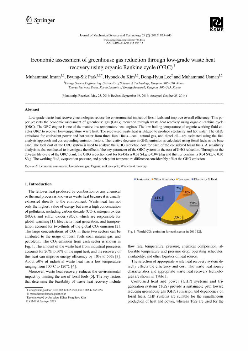
The leftover heat produced by combustion or any chemical or thermal process is known as waste heat because it is usually exhausted directly to the environment. Waste heat has not only the highest value of exergy but also a high concentration of pollutants, including carbon dioxide (CO2), nitrogen oxides (NOX), and sulfur oxides (SOX), which are responsible for global warming [1]. Electricity, heat generation, and transpor-tation account for two-thirds of the global CO2 emission [2]. The large concentrations of CO2 in these two sectors can be attributed to the usage of fossil fuels coal, natural gas, and petroleum. The CO2 emission from each sector is shown in Fig. 1. The amount of the waste heat from industrial processes accounts for 20% to 50% of the input heat, and the recovery of this heat can improve energy efficiency by 10% to 50% [3]. About 50% of industrial waste heat has a low temperature ranging from 100°C to 120°C [4].
Moreover, waste heat recovery reduces the environmental impact by limiting the use of fossil fuels [5]. The key factors that determine the feasibility of waste heat recovery include
flow rate, temperature, pressure, chemical composition, al-lowable temperature and pressure drop, operating schedules, availability, and other logistics of heat source.
The selection of appropriate waste heat recovery system di-rectly effects the efficiency and cost. The waste heat source characteristics and appropriate waste heat recovery technolo-gies are shown in Table 1.
Combined heat and power (CHP) systems and tri-generation systems (TGS) provide a sustainable path toward reducing greenhouse gas (GHG) emission and dependency on fossil fuels. CHP systems are suitable for the simultaneous production of heat and power, whereas TGS are used for the
*Corresponding author. Tel.: +82 42 8653323, Fax.: +82 42 8653756 E-mail address: [email protected]
† Recommended by Associate Editor Tong Seop Kim © KSME & Springer 2015
Fig. 1. World CO2 emission for each sector in 2010 [2].
836 M. Imran et al. / Journal of Mechanical Science and Technology 29 (2) (2015) 835~843
simultaneous production of heating, cooling, and power [6]. The recovery of waste heat through CHP and TGS can in-crease the system exergy efficiency up to 70% [7, 8]. The economic aspect and feasibility of waste heat recovery-based CHP system and TGS have been analyzed in terms of their thermodynamic performance [9, 10]. The GHG emission and exergo-environmental analysis of TGS was presented by Ref. [11]. The comparison of the results with those of the conven-tional CHP system shows that the exergy efficiency of TGS is higher but its environmental effect is lower. The exergo-environmental optimization of a gas turbine-based CHP sys-tem was performed by Ref. [12] using a genetic algorithm. A sensitivity analysis was conducted at various power levels of the gas turbine and shows a decrease in the specific unit cost of fuel with an increase in net power.
The economic feasibility of the GHG reduction potential of low-grade waste heat recovery through the organic Rankine cycle (ORC) has not yet been reported in the litera-ture. The current study investigates the GHG reduction po-tential of the ORC waste heat recovery system. The study
also provides an economic assessment and examines the effect of the operating parameters of ORC on the economics of GHG reduction.
2. System description
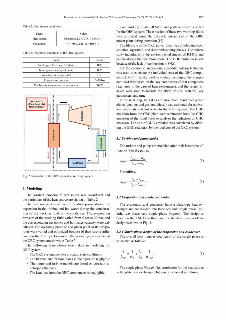
The current system has three sections: the heat source, ORC, and hot water. The schematic of the system is shown in Fig. 2.
The heat source is from a kiln with a constant flow rate and temperature recovered from the heat recovery vapor generator (HRVG).
The ORC has four main components: the HRVG, expander, condenser, and pump. An organic fluid with a low boiling point recovers the heat from the heat source in HRVG and vaporizes it. High-pressure vapors expand through the turbine to produce power. The vapors are condensed in the condenser and pumped back to the HRVG, after which the cycle is re-peated. The hot water produced by the condenser has a tem-perature of about 45°C to 50°C, which is suitable for house-hold applications.
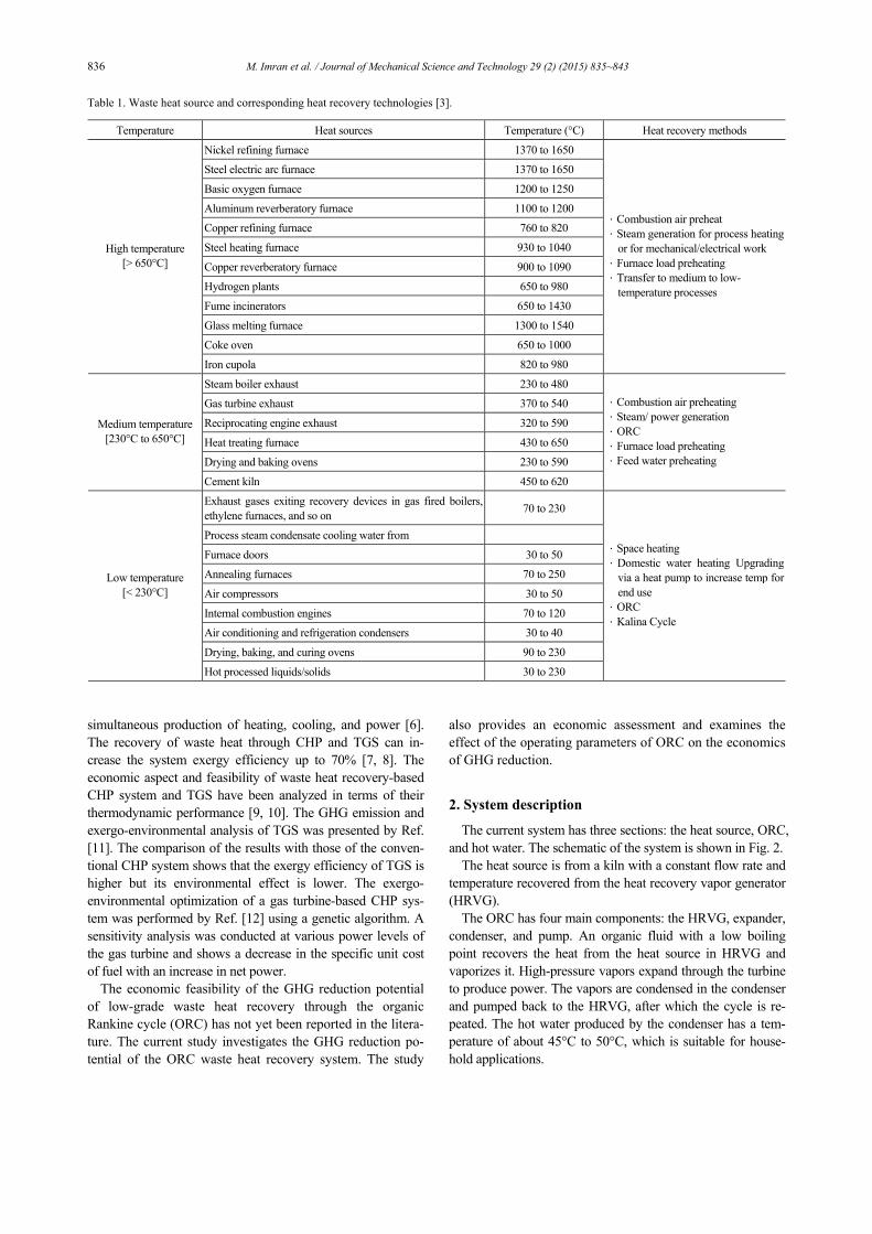
Table 1. Waste heat source and corresponding heat recovery technologies [3].
Temperature Heat sources Temperature (°C) Heat recovery methods
Nickel refining furnace 1370 to 1650
Steel electric arc furnace 1370 to 1650
Basic oxygen furnace 1200 to 1250
Aluminum reverberatory furnace 1100 to 1200
Copper refining furnace 760 to 820
Steel heating furnace 930 to 1040
Copper reverberatory furnace 900 to 1090
Hydrogen plants 650 to 980
Fume incinerators 650 to 1430
Glass melting furnace 1300 to 1540
Coke oven 650 to 1000
High temperature [> 650°C]
Iron cupola 820 to 980
·Combustion air preheat ·Steam generation for process heating
or for mechanical/electrical work ·Furnace load preheating ·Transfer to medium to low-
temperature processes
Steam boiler exhaust 230 to 480
Gas turbine exhaust 370 to 540
Reciprocating engine exhaust 320 to 590
Heat treating furnace 430 to 650
Drying and baking ovens 230 to 590
Medium temperature [230°C to 650°C]
Cement kiln 450 to 620
·Combustion air preheating ·Steam/ power generation ·ORC ·Furnace load preheating ·Feed water preheating
Exhaust gases exiting recovery devices in gas fired boilers, ethylene furnaces, and so on
70 to 230
Process steam condensate cooling water from
Furnace doors 30 to 50
Annealing furnaces 70 to 250
Air compressors 30 to 50
Internal combustion engines 70 to 120
Air conditioning and refrigeration condensers 30 to 40
Drying, baking, and curing ovens 90 to 230
Low temperature [< 230°C]
Hot processed liquids/solids 30 to 230
·Space heating ·Domestic water heating Upgrading
via a heat pump to increase temp for end use
·ORC ·Kalina Cycle
M. Imran et al. / Journal of Mechanical Science and Technology 29 (2) (2015) 835~843 837
3. Modeling
The constant temperature heat source was considered, and the particulars of the heat source are shown in Table 2.
The heat source was utilized to produce power during the expansion in the turbine and hot water during the condensa-tion of the working fluid in the condenser. The evaporation pressure of the working fluid varied from 5 bar to 20 bar, and the corresponding net power and hot water capacity were cal-culated. The operating pressure and pinch point in the evapo-rator were varied and optimized because of their strong influ-ence on the ORC performance. The operating parameters of the ORC system are shown in Table 3.
The following assumptions were taken in modeling the ORC system: • The ORC system operates at steady state conditions. • The thermal and friction losses in the pipes are negligible. • The pump and turbine models are based on constant is-
entropic efficiency. • The heat loss from the ORC components is negligible.
Two working fluids—R245fa and pentane—were selected for the ORC system. The emission of these two working fluids was estimated using the lifecycle assessment of the ORC power plant during operation [13].
The lifecycle of the ORC power plant was divided into con-struction, operation, and decommissioning phases. The current study includes only the environmental impact of R245fa and pentaneduring the operation phase. The GHG emission is low because of the lack of combustion in ORC.
For the economic assessment, a module costing technique was used to calculate the individual cost of the ORC compo-nents [14, 15]. In the module costing technique, the compo-nent cost was based on the key parameters of that component (e.g., area in the case of heat exchangers), and the proper in-dexes were used to include the effect of size, material, key parameters, and time.
In the next step, the GHG emission from fossil fuel power plants (coal, natural gas, and diesel) was estimated for equiva-lent electricity and hot water to the ORC system. The GHG emission from the ORC plant were subtracted from the GHG emission of the fossil fuels to analyze the reduction of GHG emission. The cost of GHG emission was calculated by divid-ing the GHG reduction by the total cost of the ORC system.
3.1 Turbine and pump model
The turbine and pump are modeled after their isentropic ef-ficiency. For the pump,
, .out s inisen
out in
h h
h hη
−=
− (1)
For turbine,
,.in out
isenin out s
h h
h hη
−=
− (2)
3.2 Evaporator and condenser model
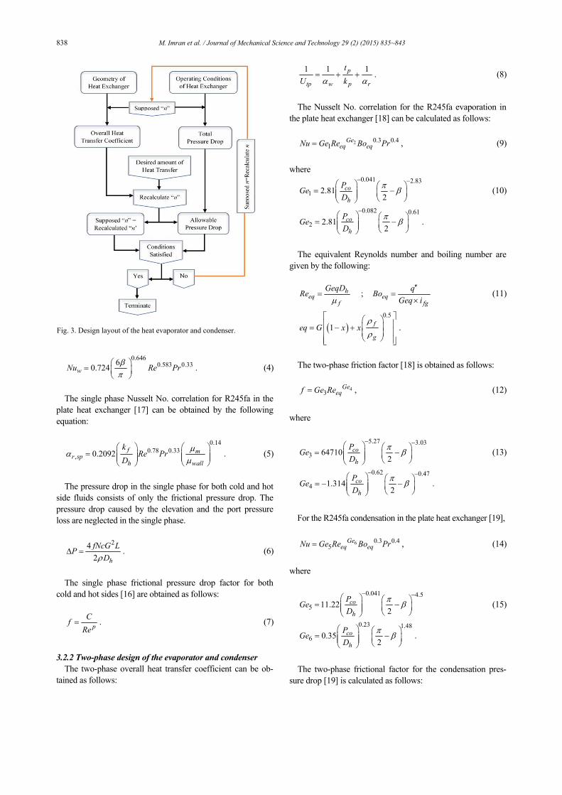
The evaporator and condenser have a plate-type heat ex-changer and are divided into three sections: single phase (liq-uid), two phase, and single phase (vapors). The design is based on the LMTD method, and the iterative process of the design is shown in Fig. 3.
3.2.1 Single phase design of the evaporator and condenser
The overall heat transfer coefficient of the single phase is calculated as follows:
,
1 1 1.p
sp w p r sp
t
U kα α= + + (3)
The single phase Nusselt No. correlation for the heat source
in the plate heat exchanger [16] can be obtained as follows:
Table 2. Heat source conditions.
Factor Value
Heat source Exhaust (51.2% CO2, 48.8% N2)
Conditions T= 180°C and 10m kg s=ɺ
Table 3. Operating conditions of the ORC system.
Factor Value
Isentropic efficiency of turbine 0.85
Isentropic efficiency of pump 0.75
Superheat at turbine inlet 2 ℃
Evaporation pressure 5–20 bar
Pinch point temperature in evaporator 10°C
Fig. 2. Schematic of the ORC waste heat recovery system.
838 M. Imran et al. / Journal of Mechanical Science and Technology 29 (2) (2015) 835~843
0.6460.583 0.336
0.7 .24wNu Re Prβπ
=
(4)
The single phase Nusselt No. correlation for R245fa in the
plate heat exchanger [17] can be obtained by the following equation:
0.14
0.78 0.33, 0.20 2 .9 f mr sp
h wall
kRe Pr
D
µα
µ
=
(5)
The pressure drop in the single phase for both cold and hot
side fluids consists of only the frictional pressure drop. The pressure drop caused by the elevation and the port pressure loss are neglected in the single phase.
24
.2 h
fNcG LP
Dρ∆ = (6)
The single phase frictional pressure drop factor for both
cold and hot sides [16] are obtained as follows:
.p
Cf
Re= (7)
3.2.2 Two-phase design of the evaporator and condenser
The two-phase overall heat transfer coefficient can be ob-tained as follows:
1 1 1.p
tp w p r
t
U kα α= + + (8)
The Nusselt No. correlation for the R245fa evaporation in
the plate heat exchanger [18] can be calculated as follows:
2 0.3 0.41
Geeq eqNu Ge Re Bo Pr= , (9)
where
0.041 2.83
1 2.812
co
h
PGe
D
πβ
− − = −
(10)
0.082 0.61
2 2.812
.co
h
PGe
D
πβ
−
= −
The equivalent Reynolds number and boiling number are
given by the following:
;heq eq
f fg
GeqD qRe Bo
Geq iµ′′
= =×
(11)
( )0.5
1f
geq G x x
ρ
ρ
= − +
.
The two-phase friction factor [18] is obtained as follows:
43
Geeqf Ge Re= , (12)
where
5.27 3.03
3 647102
co
h
PGe
D
πβ
− − = −
(13)
0.62 0.47
4 1.3142
.co
h
PGe
D
πβ
− − = − −
For the R245fa condensation in the plate heat exchanger [19],
6 0.3 0.45
Geeq eqNu Ge Re Bo Pr= , (14)
where
0.041 4.5
5 11.222
co
h
PGe
D
πβ
− − = −
(15)
0.23 1.48
6 0.352
.co
h
PGe
D
πβ
= −
The two-phase frictional factor for the condensation pres-
sure drop [19] is calculated as follows:
Fig. 3. Design layout of the heat evaporator and condenser.
M. Imran et al. / Journal of Mechanical Science and Technology 29 (2) (2015) 835~843 839
43
Geeqf Ge Re= , (16)
where
4.17 7.75
7 3521.12
co
h
PGe
D
πβ
− = −
(17)
0.0925 1.3
8 1.0242
.co
h
PGe
D
πβ
− = − −
The heat transfer coefficient of the water side [16] is com-
puted as follows:
0.6460.583 0.336
0.7 .24wNu Re Prβπ
=
(18)
The pressure drop in the two phase consists of the pressure
drop caused by the acceleration of the refrigerant, change in elevation, inlet/exit manifolds, and friction inside the corru-gated plate heat exchanger. The frictional pressure drop inside the plate heat exchanger is calculated as follows:
24
= .2f
h
fNcG LP
Dρ∆ (19)
The pressure drop caused by acceleration is represented by
the following:
( )2ac r g fP G x v v∆ = × × − , (20)
where rG is the channel flow area
.rr
p
mG
b Nc W
°=
× × (21)
The change in the pressure caused by the elevation is calcu-
lated as follows:
.elev m eP g Lρ∆ = × × (22)
The port pressure drop can be obtained as follows:
21.5.
2r m
portG v
P× ×
∆ = (23)
3.3 Economic modeling
The maintenance cost is not included in the economic mod-eling. The cost of individual components is calculated using the appropriate chemical engineering plant cost index for 2013. The cost of the evaporator and condenser are given as
( ){ }1, 2, , ,527.7
397HX S HX HX HX M HX P HXC F Ć B B F F= + , (24)
where SF is an additional factor for the overhead cost,
1,HXB and 2,HXB are constants for the heat exchanger type, and ,M HXF is the additional material factor for the heat ex-changer. The ,P HXF is the pressure factor for the heat ex-changer, and ĆHX is the basic cost of the heat exchanger made from stainless steel. The basic cost of the heat exchanger is given in terms of the following heat transfer area:
( ) ( )21 2 3log log log .HX HX HX HX HX HXĆ K K A K A= + + (25)
1, 2,, ,HX HXK K and 3,HXK are the constants for the type of heat exchanger. The pressure factor is given by the follow-ing:
( ) ( )21 2 3log log lo .gPHX HX HX HX HX HXF C C P C P= + + (26)
1, 2,, ,HX HXC C and 3,HXC are the constants for the heat exchanger type. The total cost of the pump is obtained as fol-lows:
( ){ }1, 2, , ,527.7
.397PP S PP PP PP M PP P PPC F Ć B B F F= + (27)
1,PPB and 2,PPB are the constants for the pump type,
,M PPF is the additional material factor, ,P HXF is the pres-sure factor for the pump, and ĆHX is the basic cost of the pump. The basic cost of the pump is given in terms of pump power:
( ) ( )21 2 3log log log .PP PP PP PP PP PPĆ K K W K W= + + (28)
1, 2,, ,PP PPK K and 3,PPK are the constants for the pump type. The pressure factor for the pump is calculated as fol-lows:
( ) ( )2, 1, 2, 3,log l .og logP PP PP PP PP PP PPF C C P C P= + + (29)
1, 2,, ,PP PPC C and 3,PPC are the constants for the pump type. The cost of the turbine is given by the following:
,527.7
3.
97TR S TR M TRC F Ć F= × × × (30)
,M TRF is the pressure and material factor for the turbine, and ĆTR is the basic cost of the turbine.
( ) ( )21, 2, 3,log log log .TR TR TR TR TR TRĆ K K W K W= + + (31)
840 M. Imran et al. / Journal of Mechanical Science and Technology 29 (2) (2015) 835~843
1, 2,, ,TR TRK K and 3,TRK are the constants for the turbine type. The specific investment cost is calculated by the follow-ing relation:
( )W W
.t pSpecific InvestmentCost SICTC
−= (32)
The constants for the economic modeling of the ORC sys-
tem are shown in Table 4.
3.4 Greenhouse gas emission
The emission from the fossil fuel power plant was estimated using the fuel analysis approach [20]. Three different fossil fuel power generation systems were investigated: coal, natural gas, and diesel oil. The GHGs associated with the burning of fossil fuel are mainly CO2, CH4, and N2O. CO2 is the major contribution of GHG emission from fossil fuel. Thus, the ef-fect of CH4 and N2O is calculated relative to CO2. The fuel analysis approach is adopted to calculate the CO2 emission as follows:
( ) ( ) ( )( )
2 .2
.
. . . .n
m wf i i ii
m wi
COCO kg m HC C FO
C
=
∑ , (33)
where iHC is the heat content, iC is the carbon content,
iFO is the fraction of oxidized fuel, and .m w is the mo-lecular weight. The CH4 and N2O emissions are calculated by the following:
( )4 S sCH Emission kg A EF= ×
( )2 S sN O Emission kg A EF= × (34)
where SA is the activity level of a specific source category, and sEF is the emission factor of that category. The 4CH and 2N O emissions depend on fuel type, combustion tech-nology, combustion characteristics, and control technologies.
The environmental protection agency provides the basic guidelines for estimating the activity level based on fuel type, fuel combustion technology and characteristics, control tech-nologies, and specific application.
4. Results and discussion
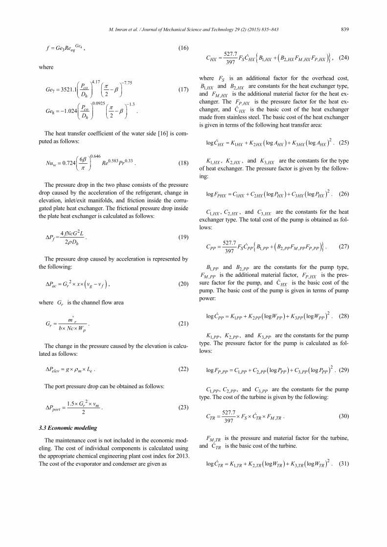
The GHG emission of ORC plants is less than that of con-ventional fossil fuel power plants because no combustion is involved in the former. The equivalent CO2 for the ORC and fossil fuel power sources are shown in Fig. 4.
Coal has the highest emission, and ORC has the lowest emission value of equivalent CO2. The selected working fluid affects the CO2 emission to some extent, but it is negligible compared with fossil fuel power sources.
GHG emission is directly related to the power produced and the annual equivalent CO2 from 10 kW to 200 kW for fossil fuel; ORC is shown in Fig. 5. At a small power capacity, the difference in the GHG emissions of ORC and fossil fuel is negligible. After 50 kW, the difference increases rapidly. In the current scenario, the net power of R245fa and pentane was calculated under the considered conditions.
The amount of GHG emission that can be reduced per an-
Table 4. Constants for economic modeling.
Cont. Value Cont. Value Cont. Value
SF 1.700 2,HXK –0.1557 1,PPB 1.890
1,HXB 0.960 3,HXK 0.1547 2,PPB 1.350
2,HXB 1.210 1,HXC 0.0000 ,M PPF 2.200
,M HXF 2.400 2,HXC 0.0000 1,PPK 3.389
1,HXK 4.660 3,HXC 0.0000 2,PPK 0.536
,M TRF 3.500 2,PPC 0.3957 3,PPK 0.153
1,TRK 2.265 3,PPC –0.0022 1,PPC –0.393
2,TRK 1.439 3,TRK –0.1776 3,TRK –0.177
Fig. 4. Equivalent CO2 emission from different power sources.
Fig. 5. Greenhouse gas emission variation with net power.
M. Imran et al. / Journal of Mechanical Science and Technology 29 (2) (2015) 835~843 841
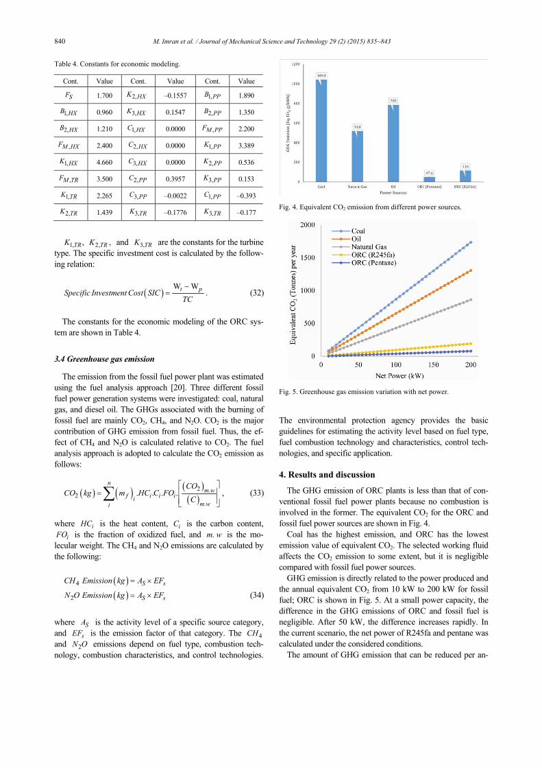
num by this power, taking the equivalent power of fossil fuels as base, is shown in Figs. 6 and 7.
The GHG emission reduction of the R245fa-based ORC system is much higher than that of the pentane-based ORC system. The net power produced by the two working fluids at
the same operating condition is different. Therefore, the GHG emission reduction potential of both working fluids is also different.
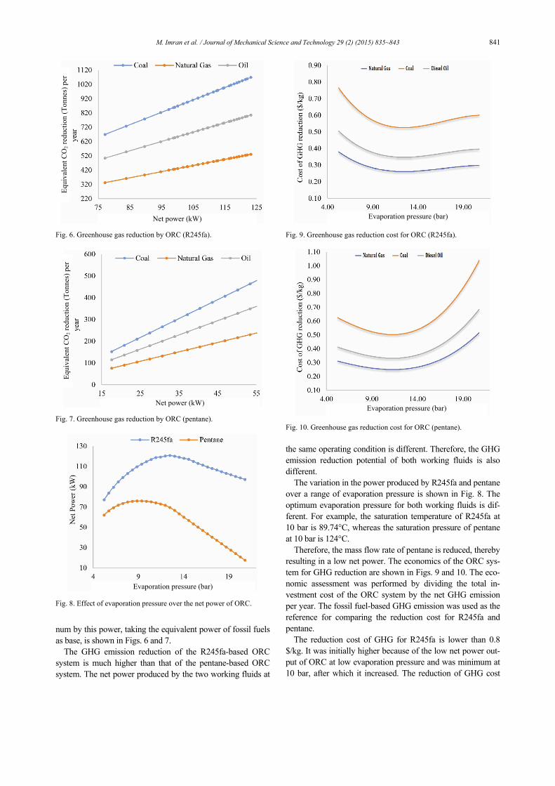
The variation in the power produced by R245fa and pentane over a range of evaporation pressure is shown in Fig. 8. The optimum evaporation pressure for both working fluids is dif-ferent. For example, the saturation temperature of R245fa at 10 bar is 89.74°C, whereas the saturation pressure of pentane at 10 bar is 124°C.
Therefore, the mass flow rate of pentane is reduced, thereby resulting in a low net power. The economics of the ORC sys-tem for GHG reduction are shown in Figs. 9 and 10. The eco-nomic assessment was performed by dividing the total in-vestment cost of the ORC system by the net GHG emission per year. The fossil fuel-based GHG emission was used as the reference for comparing the reduction cost for R245fa and pentane.
The reduction cost of GHG for R245fa is lower than 0.8 $/kg. It was initially higher because of the low net power out-put of ORC at low evaporation pressure and was minimum at 10 bar, after which it increased. The reduction of GHG cost
Fig. 6. Greenhouse gas reduction by ORC (R245fa).
Fig. 7. Greenhouse gas reduction by ORC (pentane).
Fig. 8. Effect of evaporation pressure over the net power of ORC.
Fig. 9. Greenhouse gas reduction cost for ORC (R245fa).
Fig. 10. Greenhouse gas reduction cost for ORC (pentane).
Net power (kW)
Net power (kW)
Evaporation pressure (bar)
Evaporation pressure (bar)
Evaporation pressure (bar)
Equ
ival
ent C
O2
redu
ctio
n (T
onne
s) p
er
Equ
ival
ent C
O2
redu
ctio
n (T
onne
s) p
er
842 M. Imran et al. / Journal of Mechanical Science and Technology 29 (2) (2015) 835~843
was followed by the net power output of the ORC system. A similar trend was observed for pentane, which showed a rela-tively high GHG reduction cost because of its low net power.
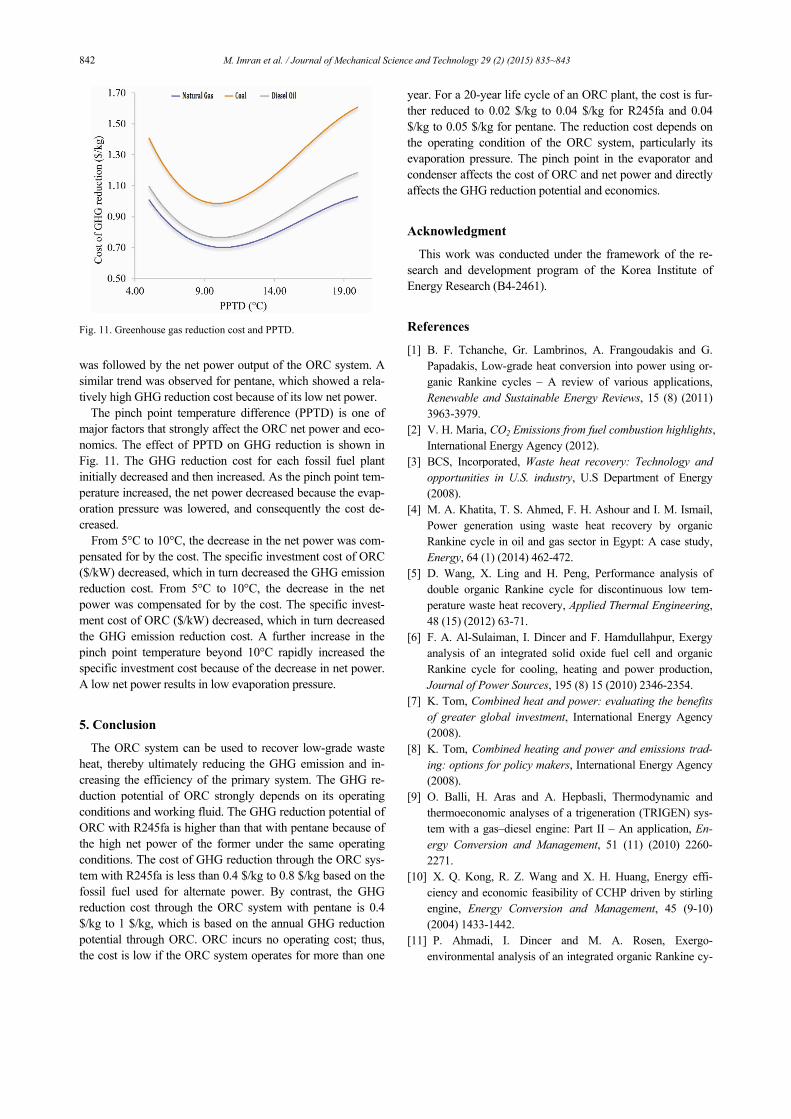
The pinch point temperature difference (PPTD) is one of major factors that strongly affect the ORC net power and eco-nomics. The effect of PPTD on GHG reduction is shown in Fig. 11. The GHG reduction cost for each fossil fuel plant initially decreased and then increased. As the pinch point tem-perature increased, the net power decreased because the evap-oration pressure was lowered, and consequently the cost de-creased.
From 5°C to 10°C, the decrease in the net power was com-pensated for by the cost. The specific investment cost of ORC ($/kW) decreased, which in turn decreased the GHG emission reduction cost. From 5°C to 10°C, the decrease in the net power was compensated for by the cost. The specific invest-ment cost of ORC ($/kW) decreased, which in turn decreased the GHG emission reduction cost. A further increase in the pinch point temperature beyond 10°C rapidly increased the specific investment cost because of the decrease in net power. A low net power results in low evaporation pressure.
5. Conclusion
The ORC system can be used to recover low-grade waste heat, thereby ultimately reducing the GHG emission and in-creasing the efficiency of the primary system. The GHG re-duction potential of ORC strongly depends on its operating conditions and working fluid. The GHG reduction potential of ORC with R245fa is higher than that with pentane because of the high net power of the former under the same operating conditions. The cost of GHG reduction through the ORC sys-tem with R245fa is less than 0.4 $/kg to 0.8 $/kg based on the fossil fuel used for alternate power. By contrast, the GHG reduction cost through the ORC system with pentane is 0.4 $/kg to 1 $/kg, which is based on the annual GHG reduction potential through ORC. ORC incurs no operating cost; thus, the cost is low if the ORC system operates for more than one
year. For a 20-year life cycle of an ORC plant, the cost is fur-ther reduced to 0.02 $/kg to 0.04 $/kg for R245fa and 0.04 $/kg to 0.05 $/kg for pentane. The reduction cost depends on the operating condition of the ORC system, particularly its evaporation pressure. The pinch point in the evaporator and condenser affects the cost of ORC and net power and directly affects the GHG reduction potential and economics.
Acknowledgment
This work was conducted under the framework of the re-search and development program of the Korea Institute of Energy Research (B4-2461).
References
[1] B. F. Tchanche, Gr. Lambrinos, A. Frangoudakis and G. Papadakis, Low-grade heat conversion into power using or-ganic Rankine cycles – A review of various applications, Renewable and Sustainable Energy Reviews, 15 (8) (2011) 3963-3979.
[2] V. H. Maria, CO2 Emissions from fuel combustion highlights, International Energy Agency (2012).
[3] BCS, Incorporated, Waste heat recovery: Technology and opportunities in U.S. industry, U.S Department of Energy (2008).
[4] M. A. Khatita, T. S. Ahmed, F. H. Ashour and I. M. Ismail, Power generation using waste heat recovery by organic Rankine cycle in oil and gas sector in Egypt: A case study, Energy, 64 (1) (2014) 462-472.
[5] D. Wang, X. Ling and H. Peng, Performance analysis of double organic Rankine cycle for discontinuous low tem-perature waste heat recovery, Applied Thermal Engineering, 48 (15) (2012) 63-71.
[6] F. A. Al-Sulaiman, I. Dincer and F. Hamdullahpur, Exergy analysis of an integrated solid oxide fuel cell and organic Rankine cycle for cooling, heating and power production, Journal of Power Sources, 195 (8) 15 (2010) 2346-2354.
[7] K. Tom, Combined heat and power: evaluating the benefits of greater global investment, International Energy Agency (2008).
[8] K. Tom, Combined heating and power and emissions trad-ing: options for policy makers, International Energy Agency (2008).
[9] O. Balli, H. Aras and A. Hepbasli, Thermodynamic and thermoeconomic analyses of a trigeneration (TRIGEN) sys-tem with a gas–diesel engine: Part II – An application, En-ergy Conversion and Management, 51 (11) (2010) 2260-2271.
[10] X. Q. Kong, R. Z. Wang and X. H. Huang, Energy effi-ciency and economic feasibility of CCHP driven by stirling engine, Energy Conversion and Management, 45 (9-10) (2004) 1433-1442.
[11] P. Ahmadi, I. Dincer and M. A. Rosen, Exergo-environmental analysis of an integrated organic Rankine cy-
Fig. 11. Greenhouse gas reduction cost and PPTD.
M. Imran et al. / Journal of Mechanical Science and Technology 29 (2) (2015) 835~843 843
cle for trigeneration, Energy Conversion and Management, 64 (2012) 447-453.
[12] P. Ahmadi and I. Dincer, Exergoenvironmental analysis and optimization of a cogeneration plant system using Mul-timodal Genetic Algorithm (MGA), Energy, 35 (12) (2010) 5161-5172.
[13] C. Liu, C. He, H. Gao, H. Xie, Y. Li, S. Wu and J. Xu, The environmental impact of organic Rankine cycle for waste heat recovery through life-cycle assessment, Energy, 56 (1) (2013) 144-154.
[14] M. Li, J. Wang, S. Li, X. Wang, W. He and Y. Dai, Thermo-economic analysis and comparison of a CO2 tran-scritical power cycle and an organic Rankine cycle, Geo-thermics, 50 (2014) 101-111.
[15] M. Imran, B. S. Park, H. J. Kim, D. H. Lee, M. Usman and M. Heo, Thermo-economic optimization of regenerative or-ganic rankine cycle for waste heat recovery applications, En-ergy Conversion and Management, 87 (2014) 107-118.
[16] B. Thonon, Design method for plate evaporators and con-densers, 1st International Conference on Process Intensifica-tion for the Chemical Industry, BHR Group Conference Se-ries Publication, 18 (1995) 37-47.
[17] Y. Y. Hsieh and T. F. Lin, Saturated flow boiling heat transfer and pressure drop of refrigerant R-410A in a vertical plate heat exchanger, International Journal of Heat and Mass Transfer, 45 (5) (2002) 1033-1044.
[18] D.-H. Han, K.-J. Lee and Y.-H. Kim, Experiments on the characteristics of evaporation of R410A in brazed plate heat exchangers with different geometric configurations, Applied Thermal Engineering, 23 (10) July (2003) 1209-1225.
[19] D.-H. Han, K.-J. Lee and Y.-H. Kim, The characteristics of condensation in brazed plate heat exchangers with different chevron angles, Journal of the Korean Physical Society, 43 (1) (2003) 66-73.
[20] Direct Emissions from Stationary Combustion Sources, United States Environmental Protection Agency (EPA), May (2008).
Muhammad Imran is a Ph.D. student of Energy System Engineering at the University of Science and Technology, Daejeon, Korea. His research interests include thermodynamic analysis and optimization for sustainable energy sys-tems. The investigation of heat transfer and pressure drop characteristics of the
organic Rankine cycle working fluids in heat exchangers is one of the core research areas of his Ph.D. works.
Byung-Sik Park is a principal re-searcher at the Korea Institute of Energy Research, Korea. He received his doc-torate degree from Chungnam National University, Daejeon, Korea. He has over 20 years of experience in research and development of national projects, fo-cused on district heating, organic
Rankine cycle systems, Stirling engines, and combined heat and power systems.
Hyouck-ju Kim is a principal re-searcher at the Korea Institute of Energy Research, Korea. He received his doc-torate degree from Kuyngpook National University, Daegu, Korea. His research interests include district heating, Stirling engines, design and optimization of CHP systems, and combustion engineering.
Related Documents