© 2019 Samsung All rights reserved. ECO HP/HR Quick Reference Guide Important Notice This is not a substitute for the installation or service manuals. As new products are released, this list will be updated. Samsung is in no way responsible for inaccuracies. This document is intended to be used as a reference.

Welcome message from author
This document is posted to help you gain knowledge. Please leave a comment to let me know what you think about it! Share it to your friends and learn new things together.
Transcript
© 2019 Samsung All rights reserved.
ECO HP/HRQuick Reference Guide
Important NoticeThis is not a substitute for the installation or service manuals. As new products are released, this list will be updated.
Samsung is in no way responsible for inaccuracies. This document is intended to be used as a reference.
© 2019 Samsung All rights reserved.
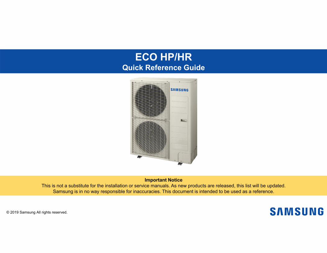
System Communication Wiring Guide 2
���������
(F3,F4) or (3,4)
Indoor unit PCB
ODU to IDU Communications
5vdc
12 vdc Samsung
accessories
To Controller485 & 12 Vdc
Outdoor Unit Terminal Block Wired Remote to Indoor Unit Terminal Block
Indoor Unit Terminal Block
F1 F2 V1 V2 F3 F4F1 F2 – Set Layer:
ODU to IDU Communications 5vdc
R1 R2 – Control Layer: Outdoor Unit to DMS Centralized Control

© 2019 Samsung All rights reserved.
Piping Design 3
Standard HP: Y piping for heat pump application Refrigeration piping:• All piping specifications must be followed to insure that the system will
operate properly.• Maintain a minimum straight line distance: ≥ 20” before connecting to
a Y-joint.• Minimum 36” straight line between Y-joints. HR Changer: Mandatory device for indoor unit mode changeover HR Changer is installed as the first device in the refrigerant piping
network. (Heat recovery only) Cool-only indoor unit is connected to the HR Changer low pressure
gas and liquid outgoing pipes. Sub MCU required for additional indoor unit zones after the HR
Changer
Standard HR: Piping for heat recovery applicationSub MCUHR Changer Cool-only unit
Paired ports to increase capacity

© 2019 Samsung All rights reserved.
HR & Sub MCU Chart 4

© 2019 Samsung All rights reserved.
Note: Power must be off, complete prior to auto addressing
Pairing DIP switch No.
ON(Individual
setting)
OFF(Paired setting)
1 A & B not paired A & B paired
2 C & D not paired C & D paired
3 E & F not paired E & F paired
4 N/A N/A
Port assign DIP switch No.
ON(Port Used)
OFF(Port not used)
1 Port A used Port A not used
2 Port B used Port B not used
3 Port C used Port C not used
4 Port D used Port D not used
Second DIP switch bank 1 Port E used Port E not used
2 Port F used Port F not used
Use the rotary dial to give each MCU its ownindividual address
10’s
1’s
MCU Settings (HR changer & Sub changer) 5
F E D C B A
Example: Port “C” not used. Capacity per port (≤19 MBtu)
MCU address setting rotary’s
A B C D E F

© 2019 Samsung All rights reserved.
Indoor unit quantity Rotary Dial. Outdoor unit option settings--DIP switches.
Commissioning & Service modesK1 K2 K3 K4 Tactile switches
Outdoor unit option set, Indoor unit quantity set Commissioning & Service modes. K1 K2 K3 K4 Tactile switches
System PCB Identification 636, 48, & 53 MBtu/h Heat Pump Models 60 MBtu/h HP Model – All HR Models

© 2019 Samsung All rights reserved.
Set the quantity of indoor units from rotary switches: SW51 & SW52
With system powered off: Set the connected indoor unit quantity on the ODU PCB
When the ODU is powered up: The system will automatically address the IDU’s
Option: Manual addressing – remote controller or SNET Pro 2
SW51:10’s SW52:1’s
36, 48 & 53 Btu HP Initial System Settings 7

© 2019 Samsung All rights reserved.
36, 48 & 53 Btu HP Initial System Settings 8
Switch Position Function
K6ON Snow prevention (Used) Default
OFF Snow prevention (Not used)
K7 & K8
ON ON (Target evap temp) 7-9 ⁰C / 44.6-48.2 ⁰F Default
ON OFF 5-7 ⁰C / 41-44.6 ⁰F
OFF ON 9-11 ⁰C / 48.2-51.8 ⁰F
OFF OFF 10-12 ⁰C / 50-53.6 ⁰F
K9 & K10
ON ON Night quiet mode not used Default
ON OFF Step – 1
OFF ON Step – 2
OFF OFF Step - 3

© 2019 Samsung All rights reserved.
36, 48 & 53 Btu HP Initial System Settings 8
Switch Position Function
K11 & K12
ON ON Capacity correction heating Default
ON OFF Default – 28.4 psi
OFF ON Default – 14.2 psi
OFF OFF Default + 14.2 psi
K13 & K14
ON ON 3 ton Default 4 + ton Default
ON OFF Max current (–) 4(A) Max current (–) 2A)
OFF ON Max current (–) 6(A) Max current (–) 4(A)
OFF OFF Max current (–) 8(A) Max current (–) 6(A)
K15 & K16
ON ON MID Default
ON OFF MID
OFF ON LOW1 (Humidity)
OFF OFF LOW2 (Humidity)

© 2019 Samsung All rights reserved.
36,48&53 MBtu/h HP models
Defrost mode can start after 30 minutes of heat operation run time, and the suction temperature at the outdoor unit heat exchanger is less than 23°F, or there is a significant temperature difference between the heat exchanger suction gas and ambient.
For installations with high humidity which creates too many defrost cycles, defrost interval can be changed to LOW1 or LOW2 (K5 K6)
Heating capacity is reduced in this operation
Outdoor Unit Option Settings – Defrost Interval Adjustment 9
Switch Position Function
K15 & K16
ON ON Humidity MID1 Default
ON OFF Humidity MID2
OFF ON Humidity LOW1
OFF OFF Humidity LOW2

© 2019 Samsung All rights reserved.
Step Button press Display Description Note
Step 1 Power on unit id nd Indoor setting required -
Quantity of indoor units
Step 2 Press K1 & K2 for 2 seconds id 00 Ready to set -
Step 3
K2 id X0 Ten digit setting-
K4 id 0X Ones digit setting
Hold K4 for 2 seconds to start auto detection mode
Heat pumps hold K2 to save and exit. Segment will display Ad 00 then UP.
Quantity of MCU (HR only)
Step 4 Press K1 NC 00 Ready to set (Default)
Step 5
K2 NC X0 Ten digit setting-
K4 NC 0X Ones digit setting
Hold K4 for 2 seconds for auto detection mode
Heat recovery setting
Step 6 Press K1 ht 00 System type -
Step 7 Press K4ht 00 Heat pump (Default)
ht 01 Heat Recovery Must set
Step 8 Hold K2 Exit Save Unit will display E201 or E213
All units powered on
Indoor unit count
Outdoor Type
Finished
MCU countHR only
60 Btu HP/HR Initial System Settings 10

© 2019 Samsung All rights reserved.
Note: MCU address and dip switch settings must be completed before Auto Pipe Pairing operation is initiated
The outdoor unit will display E213 if addressing has not been completed
The Indoor Unit MICOM firmware version must be “161222” or higher see next slideyr./month/day
To run the Auto Pipe Pairing operation, take the following steps:
1.Press the K2 button 10 times on the main PBA of the outdoor unit to start the Auto pipe pairing operation. (Display : )
- The operation takes about 25 to 55minutes normally depending on the number of indoor units connected.(Max 2hours)
Step 1 (Start ) → Steps 2 - 8 (Setup ) → Step 9 (Check ) → Step 10 (Confirmation )
Temperature Outdoor temp < 75℉ Outdoor temp 75℉ ≥ 85℉ Outdoor temp ≥ 86℉
Avg. Indoor temp <75℉Main heating operation
Main heating operationMain cooling operation
Avg. Indoor temp ≥75℉ Main cooling operation
Note: Verify service valves are open and the proper charge has been added
MCU Auto Pipe Pairing Auto Addressing (H/R only)
11

© 2019 Samsung All rights reserved.
1. Press and hold K2 to enter the option setting.(system must be thermo-off) -display will show as follows:
SEG 1, 2 SEG 3, 4
-SEG 1 & 2 will display the number of the optional setting.-SEG 3 & 4 will display the number of set value for the function setting.
2. Shortly press the K1 button to adjust the value of SEG 1 & 2 to match the desired option number.
-Example:
SEG 3, 4SEG 1, 2 SEG 3, 4SEG 1, 2
Quickly pressing K1 button One time.
SEG 3, 4SEG 1, 2 SEG 3, 4SEG 1, 2
Quickly pressing K2 button One time.
3. Shortly press the K2 button to adjust the value of SEG 3 & 4 to match the desired option number.
-Example:
4. After setting the number values in SEG 1, 2, 3 & 4 for the function option you want to change. Press and hold the K2 button for 2 seconds or more to save.
5. All Segments will BLINK and begin tracking
NOTE:• Press and hold the
K1 button to reset values to previous settings.
• Press and hold K4 to restore to factory default settings.
• Once you release K4 for factory default wait until the system resets and starts the tracking process. Then press and hold the K2 button to save the setting.
• Press K3 at any time to exit.
Outdoor Setting
12

© 2019 Samsung All rights reserved.
Option item
Input unit SEG1 SEG2 SEG3 SEG4 Function Remarks
Cooling Correction
MainPCB 0 1
0 044-48 ( F )
Default(A type PBA)
Target Evaporator Temp ( F ) m
anual readings are ( C )
when low
er temperature value is set, discharge air Tem
p of the indoor unit w
ill decrease.
0 141-44 ( F )
Default( B type PBA)
0 2 48-51 ( F )
0 3 50-53 ( F )
0 4 51-55 ( F )
0 5 53-57 ( F )
0 6 55-57 ( F )
Outdoor Setting
13
NOTE:• Press and hold the
K1 button to reset values to previous settings.
• Press and hold K4 to restore to factory default settings.
• Once you release K4 for factory default wait until the system resets and starts the tracking process. Then press and hold the K2 button to save the setting.
• Press K3 at any time to exit.

© 2019 Samsung All rights reserved.
Optionitem Input unit SEG1 SEG2 SEG3 SEG4 Function Remarks
Heating Correction
Main & SubPCB 0 2
0 0 Default435 (PSI)
Target High Pressure (PSI)
(When low
pressure value is set, discharge air tem
perature of indoor unit will decrease).
0 1 362 (PSI)
0 2 377 (PSI)
0 3 391 (PSI)
0 4 406 (PSI)
0 5 420 (PSI)
0 6 449 (PSI)
0 7 464 (PSI)
0 8 478 (PSI)
Outdoor Setting
14
NOTE:• Press and hold the
K1 button to reset values to previous settings.
• Press and hold K4 to restore to factory default settings.
• Once you release K4 for factory default wait until the system resets and starts the tracking process. Then press and hold the K2 button to save the setting.
• Press K3 at any time to exit.

© 2019 Samsung All rights reserved.
Optionitem
Input unit SEG1 SEG2 SEG3 SEG4 Function Remarks
Current Restriction
Main PCB 0 3
0 0 100% Default
When restriction option is set, cooling and heating
performance m
ay decrease.0 1 95%
0 2 90%
0 3 85%
0 4 80%
0 5 75%
0 6 70%
0 7 65%
0 8 60%
0 9 55%
1 0 50%
1 1 No restriction
Outdoor Setting
15
NOTE:• Press and hold the
K1 button to reset values to previous settings.
• Press and hold K4 to restore to factory default settings.
• Once you release K4 for factory default wait until the system resets and starts the tracking process. Then press and hold the K2 button to save the setting.
• Press K3 at any time to exit.

© 2019 Samsung All rights reserved.
Optionitem
Input unit SEG1 SEG2 SEG3 SEG4 Function Remarks
Oil Collection
Main PCB 0 4
0 0 Default
-
0 1Shorten the Interval by
1/2
Temperature to trigger Defrost
MainPCB 0 5
0 0 Default Apply this setting w
hen installation
location is in hum
id area.(near lakes, rivers etc.).0 1 High humidity
Outdoor Fan Speed
Main &
SubPCB
0 6
0 0 Default
Changing this setting w
ill increase fan
speed to m
aximum
value.
0 1 Increase fan speed
Outdoor Setting
16
NOTE:• Press and hold the
K1 button to reset values to previous settings.
• Press and hold K4 to restore to factory default settings.
• Once you release K4 for factory default wait until the system resets and starts the tracking process. Then press and hold the K2 button to save the setting.
• Press K3 at any time to exit.

© 2019 Samsung All rights reserved.
Optionitem
Input unit SEG1 SEG2 SEG3 SEG4 Function Remarks
Silent mode Main PCB 0 7
0 0 Disabled Default
If enabled in AUTO
this function will operate
automatically (C
ooling mode only)
(MIM
-B14) is needed to control night mode by
contact for both heating and cooling. 0 1 Level 1 /
Auto
0 2 Level 2 / Auto
0 3 Level 3 / Auto
0 4Level 1 External contact
0 5Level 2 External Contact
0 6Level 3 External contact
Outdoor Setting
17
NOTE:• Press and hold the
K1 button to reset values to previous settings.
• Press and hold K4 to restore to factory default settings.
• Once you release K4 for factory default wait until the system resets and starts the tracking process. Then press and hold the K2 button to save the setting.
• Press K3 at any time to exit.

© 2019 Samsung All rights reserved.
Optionitem
Input unit SEG1 SEG2 SEG3 SEG4 Function Remarks
High-head condition
Main PCB 0 8
0 0 DisabledDefault -
0 1
Level 1 Type 1
Indoor lower than outdoor
unit
When
outdoor unit is located 131-262ft
above indoor units.
0 2 Unused
0 3Type 2
Outdoor unit lower than indoor unit
When
indoor units are over 98ft above the outdoor
unit.
Long –piping condition
(cannot be set with high-
head setting)
Main PCB 0 9
0 0 Disabled Default -
0 1 Level 1
When
equivalent length of
farthest indoor unit from
the outdoor unit is
over 328ft.
0 2 Unused
Outdoor Setting
18
NOTE:• Press and hold the
K1 button to reset values to previous settings.
• Press and hold K4 to restore to factory default settings.
• Once you release K4 for factory default wait until the system resets and starts the tracking process. Then press and hold the K2 button to save the setting.
• Press K3 at any time to exit.
© 2019 Samsung All rights reserved.
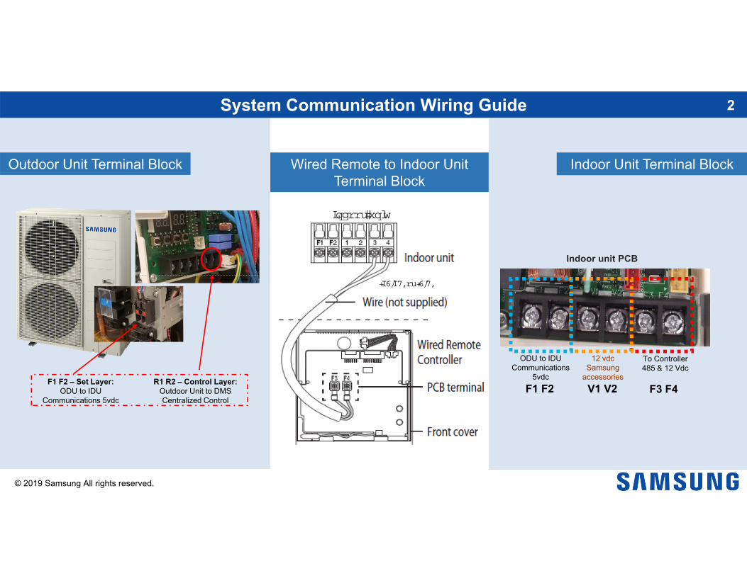
Option item Input unit SEG1 SEG2 SEG3 SEG4 Function Remarks
Energy savingsmode
MainPCB 1 0
0 0 Disable Default
0 1 Energy saving mode
Energy saving triggers when
the room tem
perature reaches desired set-point
(Heating m
ode only).
0 2 Rapid Cooling
Increase cooling speed.
Outdoor Setting
19
NOTE:• Press and hold the
K1 button to reset values to previous settings.
• Press and hold K4 to restore to factory default settings.
• Once you release K4 for factory default wait until the system resets and starts the tracking process. Then press and hold the K2 button to save the setting.
• Press K3 at any time to exit.
© 2019 Samsung All rights reserved.
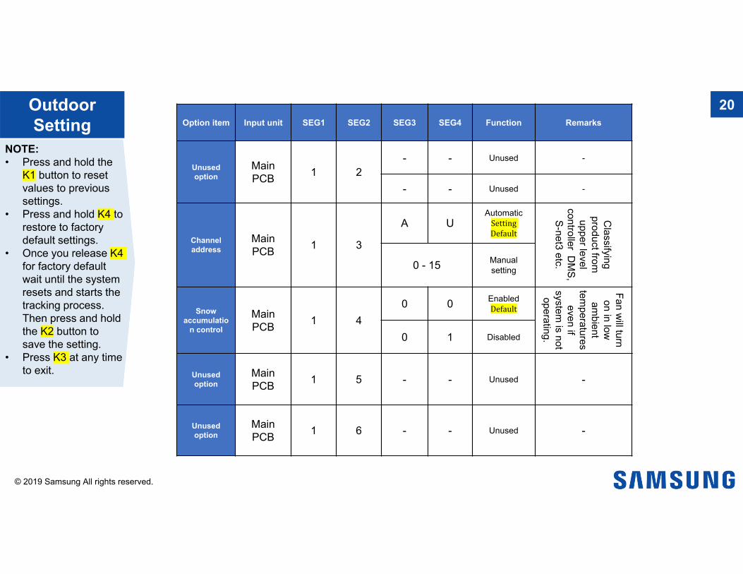
Option item Input unit SEG1 SEG2 SEG3 SEG4 Function Remarks
Unusedoption
Main PCB 1 2
- - Unused -
- - Unused -
Channel address
MainPCB 1 3
A UAutomatic
Setting Default
Classifying
product from
upper level controller D
MS,
S-net3 etc.0 - 15 Manual setting
Snow accumulatio
n control
MainPCB 1 4
0 0 Enabled Default
Fan will turn
on in low
ambient
temperatures even if
system is not
operating.0 1 Disabled
Unusedoption
MainPCB 1 5 - - Unused -
Unusedoption
MainPCB 1 6 - - Unused -
Outdoor Setting
20
NOTE:• Press and hold the
K1 button to reset values to previous settings.
• Press and hold K4 to restore to factory default settings.
• Once you release K4 for factory default wait until the system resets and starts the tracking process. Then press and hold the K2 button to save the setting.
• Press K3 at any time to exit.

© 2019 Samsung All rights reserved.
Option item Input unit SEG1 SEG2 SEG3 SEG4 Function Remarks
Unused option MainPCB 1 7
- -Unused -
- -
Max. Capacity restriction
MainPCB 1 8
0 0 Enabled Default
Restrict excessive
capacity increase w
hen operating sm
all indoor unit capacity.0 1 Disable
Gas leak Pump down
MainPCB 1 9
0 0 Disabled Default
When gas leak is
detected enter the pum
p down
operation. 0 1 Enable
Unused option Main PCB 2 0 0 0 Unused -
Unused option Main PCB 2 1
- -Unused -
- -
Outdoor Setting
21
NOTE:• Press and hold the
K1 button to reset values to previous settings.
• Press and hold K4 to restore to factory default settings.
• Once you release K4 for factory default wait until the system resets and starts the tracking process. Then press and hold the K2 button to save the setting.
• Press K3 at any time to exit

© 2019 Samsung All rights reserved.
Option item Input unit SEG1 SEG2 SE03 SEG4 Function Remarks
Emergency operation
indoor unit error
Main PCB 2 2
0 0 Disabled Default
When set operation
is possible even if an indoor
comm
unication error occurs.
0 1Indoor high
humidity condition
0 2 Indoor unit low humidity
Base heater Main PCB 2 3
0 0 Disabled Default
-0 1 Enabled
Unused option
Main &
SubPCB
0 0
- -
Unused -- -
- -
Outdoor Setting
22
NOTE:• Press and hold the
K1 button to reset values to previous settings.
• Press and hold K4 to restore to factory default settings.
• Once you release K4 for factory default wait until the system resets and starts the tracking process. Then press and hold the K2 button to save the setting.
• Press K3 at any time to exit

© 2019 Samsung All rights reserved.
Once all equipment is communicating and auto piping has successfully completed. UP will be displayed on the main PCB.
Before entering auto trial operation:• All option settings should be made through the
outdoor PCB and S-Net. • Verify that the proper charge has been added and
the service valves are fully open.
To enter Auto Trial Operation• Press and hold K1 for 5 seconds.• The display will change to “K”“K”.• Once successfully completing Auto Trial the
system will stop operation and the display will begin to scroll connected equipment addressing.
UP Un-Prepared 23
K1 K2 K3 K4

© 2019 Samsung All rights reserved.
K1 Control Key operation Display on segmentPress and Hold Auto trial operation “K” “K” “BLANK” “BLANK”
K1 No. of presses Key Operation Display on segment1 time Refrigerant charging in Heating “K” “1” “BLANK” “BLANK”
2 times Trial operation in Heating “K” “2” “BLANK” “BLANK”
3 times Pump out in Heating “K” “3” “BLANK” “1”
4 times Vacuuming “K” “4” “BLANK” “1”
5 times End Key -
View Mode - Key Operation 24

© 2019 Samsung All rights reserved.
K2 No. of presses Key operation Display on segments
1 time Refrigerant charging in Cooling “K” “5” “BLANK” “BLANK”
2 times Trial operating in Cooling “K” “6” “BLANK” “BLANK”
3 times Pump down all units in Cooling “K” “7” “BLANK” “BLANK”
4 times Automatic setting of operation mode (Cooling/Heating) for trial operation) “K” “8” “BLANK” “BLANK”
5 times Refrigerant check mode “K” “9” X-X
6 times Discharge made DC line voltage “K” “A” “BLANK” “BLANK”
7 times Forced defrost “K” “B” “BLANK” “BLANK”
8 time Forced oil return “K” “C” “BLANK” “BLANK”
9 times Inverter compressor check “K” “D” “BLANK” “BLANK”
10 times H/R: Piping check operation H/P not used “K” “E” “BLANK” “BLANK”
11 times End Key operation -
K3 No. of presses Key operation Display on segment1 time Initialize (reset/exit) “8” “8” “8” “8” “back to main display”
View Mode - Key Operation 25
Related Documents