ECE 4901 Senior Design I, Fall 2014 Software-Defined MIMO Radio Transceiver Senior Design I - Final Report Benjamin Brown (EE), Kelsey Dutta (EE/PNB), and Clifroy Henry (CMPE) Sponsor Contact: Michael Wentz The MITRE Corporation 202 Burlington Road Bedford, MA 01730-1420

Welcome message from author
This document is posted to help you gain knowledge. Please leave a comment to let me know what you think about it! Share it to your friends and learn new things together.
Transcript
ECE 4901 Senior Design I, Fall 2014
Software-Defined MIMO Radio Transceiver
Senior Design I - Final Report
Benjamin Brown (EE), Kelsey Dutta (EE/PNB), and Clifroy Henry (CMPE)
Sponsor Contact: Michael Wentz
The MITRE Corporation
202 Burlington Road
Bedford, MA 01730-1420(781) 271-2000
Table of Contents
I. Summary …………………………………………………………………. 1II. Background ……………………………………………………………. 1-2
III. Specifications …………..………………………………………………... 2
IV. Design ……………………………………………………………………....V. Results ……………………………………………………………………....
VI. Timeline and Future Plans ...………………………………………………..VII. Budget ……………………………………………………………………....
VIII. Thanks ……………………………………………………………………....IX. References ………………………………………………………………….
I. SummaryThe MITRE corporation is a not-for-profit organization based out of Virginia and
Massachusetts. They are often contracted by the government, specifically the departments of defence and homeland security, to investigate and report on new technologies. An area of concentration for the company is in the field of communications systems, both wired and wireless. Our contact’s department has many projects which incorporate the use of USRP boards and software-defined radio (SDR) applications, such as GNU Radio.
Currently their systems rely on the use of single-input-single-output (SISO) technology, as that is the default functionality available with the software package. In order to determine the advantages which may be gained through the use of multiple-input-multiple-output(MIMO) technology, such software must be written and allocated to the existing software package. Thus, the goal of this project is to design and implement MIMO components which can be used in
conjunction with the existing GNU Radio software, and to test the capabilities of such communication schemes in different situations, the results of which are to be thoroughly documented and reported to the sponsor.
II. BackgroundWireless communication systems are used extensively in applications from commercial
and satellite radio, to GPS positioning, to WIFI, 3G and LTE phones. Many of the recent advancements in wireless communications technology have come as the result of development of MIMO algorithms and technologies. MIMO allows for several advantages over its singular predecessor including faster data transmission, more reliability, and greater signal strength. Thus, a MIMO system can provide greater capacity, range, and reliability than a SISO system. However, introducing MIMO functions into a system requires more complex data processing algorithms.
Previously, traditional radio systems required complex hardware implementations that limited their flexibility and user-accessibility. Different modulation schemes required different circuitry and hardware components to be implemented, which resulted in systems that could not switch between modulation types as readily as was necessary. Recent developments in software, as well as reconfigurable digital logic hardware (field programmable gate arrays (FPGA) and digital signal processors (DSP)) have led to new SDR systems which allow for the use of personal computers to communicate via the broadcast and reception of radio signals. One such SDR utility is GNU Radio, which is open-source and available to the public with a user-friendly interface. This software package provides the necessary tools for digital signal processing in a block diagram/signal flow type configuration. While similar signal processing could be done in MATLAB or other software not built specifically for radio, GNU Radio supplies data processing and transmission as well as an intuitive GUI that non-engineers can easily pick up and use, in addition to being free.
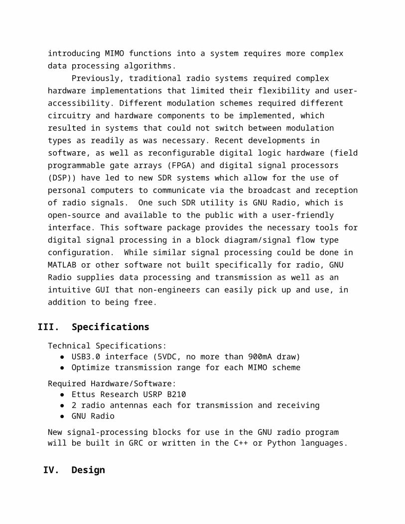
III. Specifications
Technical Specifications:● USB3.0 interface (5VDC, no more than 900mA draw)● Optimize transmission range for each MIMO scheme
Required Hardware/Software:● Ettus Research USRP B210● 2 radio antennas each for transmission and receiving● GNU Radio
New signal-processing blocks for use in the GNU radio program will be built in GRC or written in the C++ or Python languages.
IV. Design
The general model of a SISO system can be written as:
y[m] = h*x[m] + n[m]
where y is the received signal, h is the channel transfer function, x is the transmitted signal, and n is the channel noise. From this, the 2x2 MIMO equation can be easily understood:
y1[m] = h11x1[m]+h12x2[m]+n1[m]
y2[m] = h21x1[m]+h22x2[m]+n2[m]
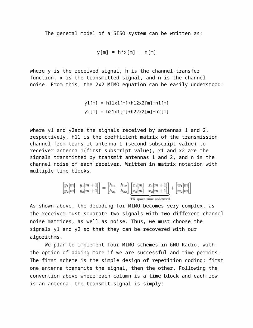
where y1 and y2are the signals received by antennas 1 and 2, respectively, h11 is the coefficient matrix of the transmission channel from transmit antenna 1 (second subscript value) to receiver antenna 1(first subscript value), x1 and x2 are the signals transmitted by transmit antennas 1 and 2, and n is the channel noise of each receiver. Written in matrix notation with multiple time blocks,
As shown above, the decoding for MIMO becomes very complex, as the receiver must separate two signals with two different channel noise matrices, as well as noise. Thus, we must choose the signals y1 and y2 so that they can be recovered with our algorithms.
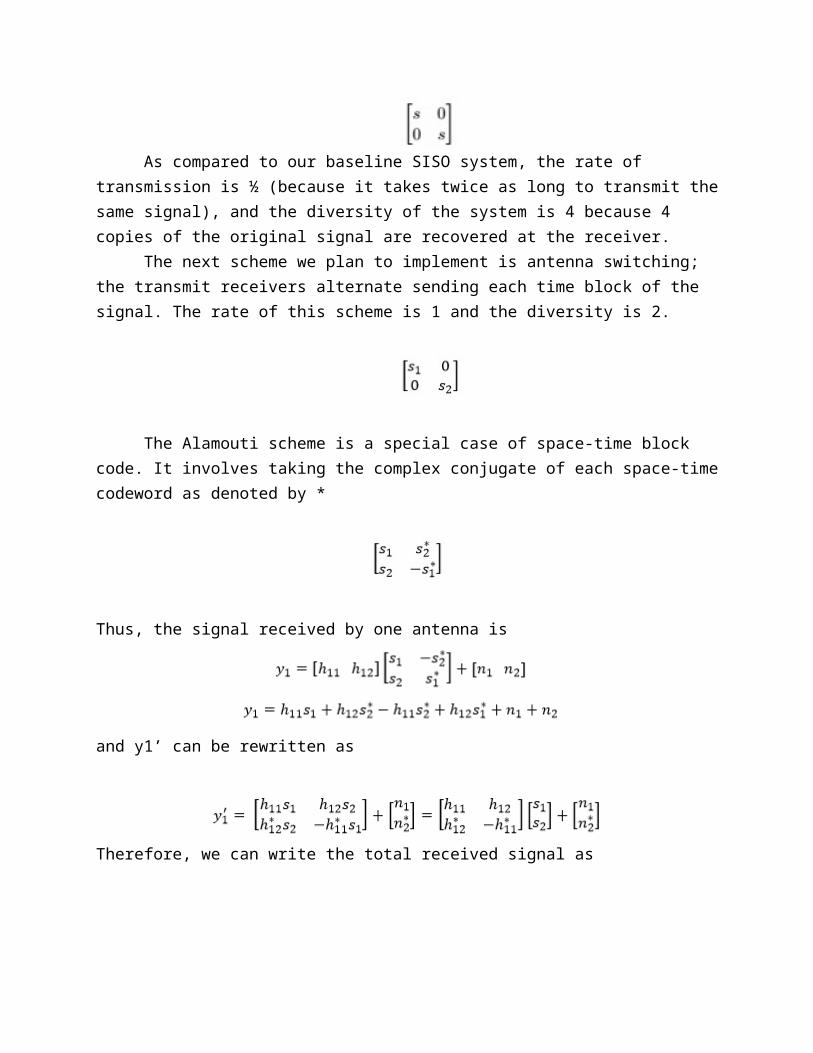
We plan to implement four MIMO schemes in GNU Radio, with the option of adding more if we are successful and time permits. The first scheme is the simple design of repetition coding; first one antenna transmits the signal, then the other. Following the convention above where each column is a time block and each row is an antenna, the transmit signal is simply:
As compared to our baseline SISO system, the rate of transmission is ½ (because it takes twice as long to transmit the same signal), and the diversity of the system is 4 because 4 copies of the original signal are recovered at the receiver.
The next scheme we plan to implement is antenna switching; the transmit receivers alternate sending each time block of the signal. The rate of this scheme is 1 and the diversity is 2.
The Alamouti scheme is a special case of space-time block code. It involves taking the complex conjugate of each space-time codeword as denoted by *
Thus, the signal received by one antenna is
and y1’ can be rewritten as
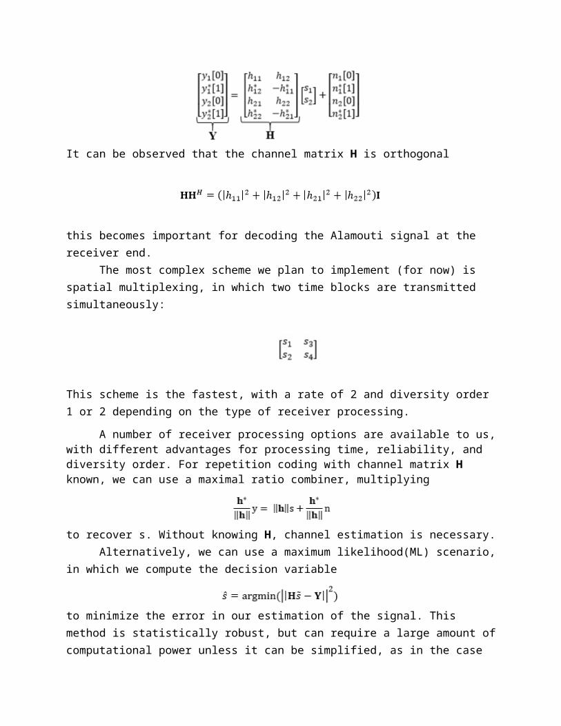
Therefore, we can write the total received signal as
It can be observed that the channel matrix H is orthogonal
this becomes important for decoding the Alamouti signal at the receiver end.The most complex scheme we plan to implement (for now) is spatial multiplexing, in
which two time blocks are transmitted simultaneously:
This scheme is the fastest, with a rate of 2 and diversity order 1 or 2 depending on the type of receiver processing.
A number of receiver processing options are available to us, with different advantages for processing time, reliability, and diversity order. For repetition coding with channel matrix H known, we can use a maximal ratio combiner, multiplying
to recover s. Without knowing H, channel estimation is necessary.Alternatively, we can use a maximum likelihood(ML) scenario, in which we compute the
decision variable
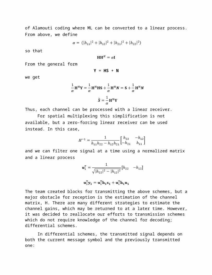
to minimize the error in our estimation of the signal. This method is statistically robust, but can require a large amount of computational power unless it can be simplified, as in the case of Alamouti coding where ML can be converted to a linear process. From above, we define
so that
From the general formY = HS + N
we get
Thus, each channel can be processed with a linear receiver.For spatial multiplexing this simplification is not available, but a zero-forcing linear
receiver can be used instead. In this case,
and we can filter one signal at a time using a normalized matrix and a linear process
The team created blocks for transmitting the above schemes, but a major obstacle for reception is the estimation of the channel matrix, H. There are many different strategies to estimate the channel gains, which may be returned to at a later time. However, it was decided to reallocate
kelsey.dutta, 12/05/14,
this is where I started adding new stuff
our efforts to transmission schemes which do not require knowledge of the channel for decoding; differential schemes.
In differential schemes, the transmitted signal depends on both the current message symbol and the previously transmitted one:
Therefore, decisions can be made about the message signal by comparing consecutive receive symbols. For proof of concept, we will first create blocks to demonstrate SISO differential phase-shift keying(PSK) blocks. In non-differential binary PSK, a 0 is encoded with a phase of 0 degrees and a 1 with 180 degrees. Thus, when the message signal switches from a 0 to 1 or 1 to 0, there is a phase reversal, and when there are consecutive 1’s or 0’s, there is no change. In differential PSK, the transmitted signal is the sum of the previously sent signal and the current message signal. Thus, a 1 bit adds a 180-degree phase, and a 0 bit does not change the current phase of the signal:
Fig. 1: Differences Between PSK and DPSK Signals
Thus, demodulating differential PSK does not require knowledge of the phase shift induced by the channel; comparing the phase of consecutive symbols reveals the original message. The received kth symbol is
where E is the transmission energy per symbol and ɸ is the phase. If the received symbol is multiplied by the conjugate of the previously received symbol:
ignoring the noise terms, the phase of the new signal isɸ k−ɸ k−1, which yields the message symbol.
Combining the general form differential scheme with Alamouti code gives the MIMO transmit signal:
This can be decoded using a maximum likelihood receiver.
V. ResultsA. Repetition Coding
Fig. 2: Diagram of Repetition Coding MIMO Block Subsystem
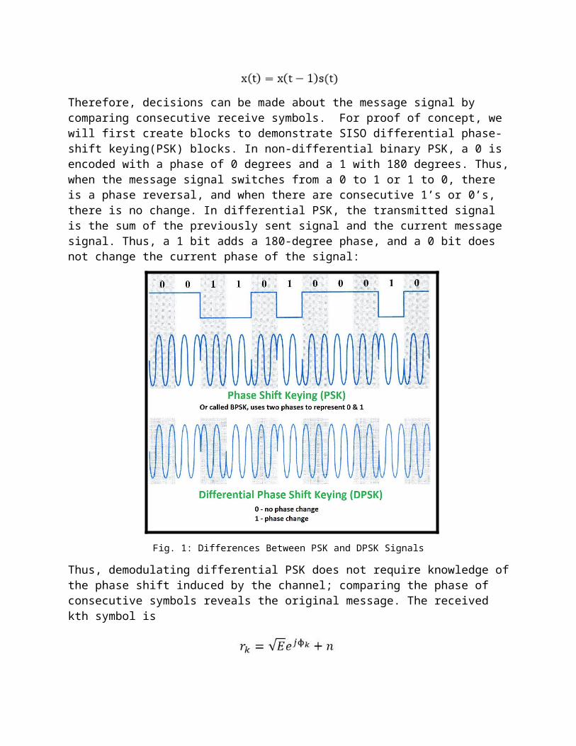
Fig. 3: Resulting Signals for Cosine Input to Repetition Coding MIMO Block (Original Signal in Dark Blue)B. Antenna Switching
Fig. 4: Diagram of Antenna Switching MIMO Block Subsystem
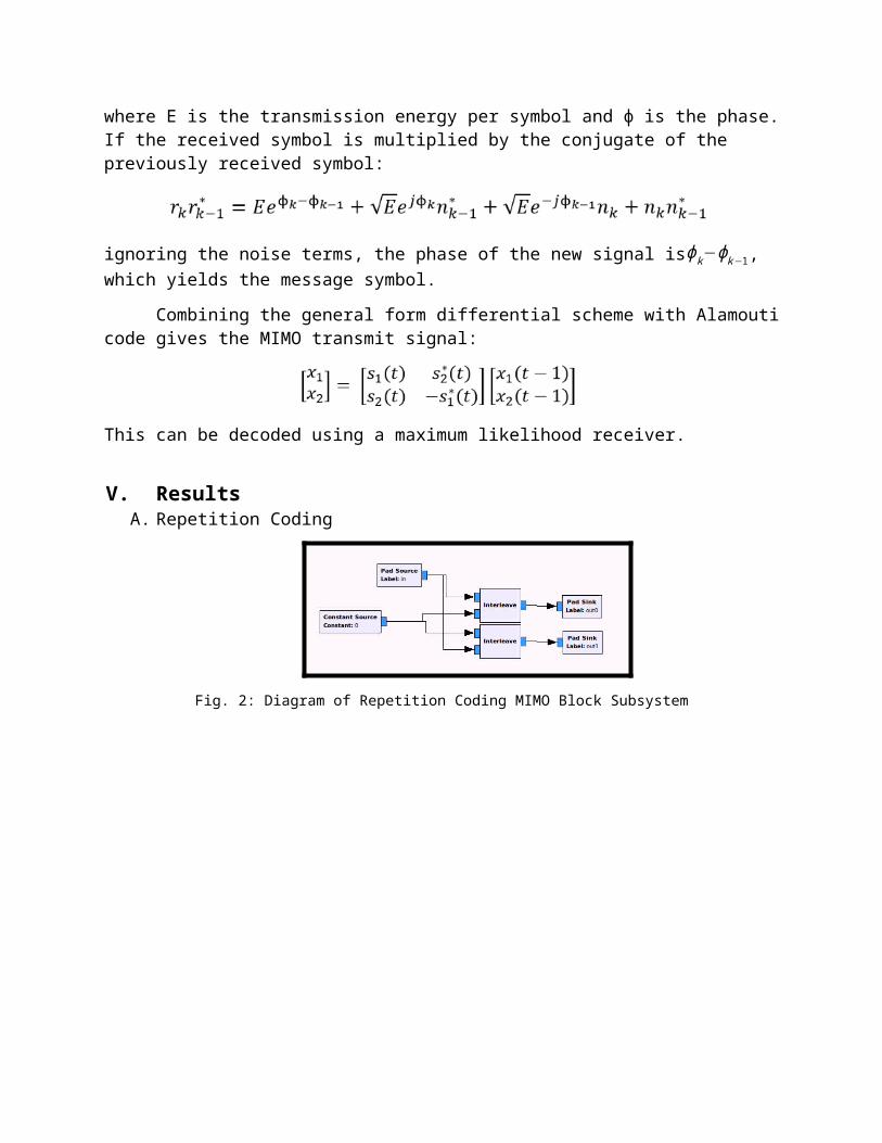
Fig. 5: Resulting Signal for Cosine Input to Antenna Switching MIMO Block (Original Signal in Dark Blue)C. Alamouti Coding
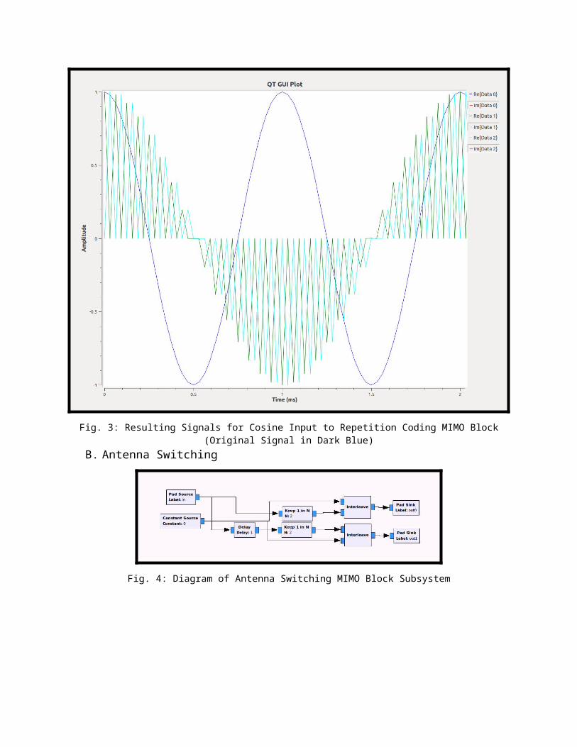
Fig. 6: Diagram of Alamouti MIMO Block Subsystem
The visualization of the Alamouti scheme does little to support proving that the block performs, so it has been omitted.
D. Spatial Multiplexing
Fig. 7: Diagram of Spatial Multiplexing MIMO Block Subsystem
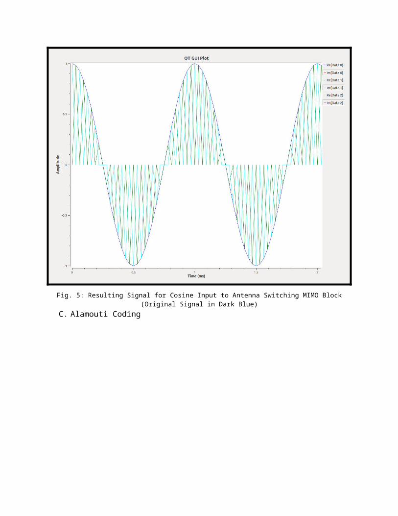
Fig.8: Resulting Signal for Cosine Input to Spatial Multiplexing MIMO Block (Original Signal in Dark Blue)E. Preliminary Over-The-Air Testing
Part of the process of developing the MIMO blocks for our sponsor will require the transmission of the signals over-the-air. Thus testing was performed using already existing blocks in GNU Radio to ensure that the procedure for transmitting can be considered known. For this test, we have set up a frequency modulated signal of a 50 kHz input cosine waveform, sent between two antennas, demodulated on the receiving end, and band-passed for signal recovery (a low-pass filter is supplied by default within the demodulation block while a high-pass filter was implemented externally of the demodulator to simulate a band-pass filter).
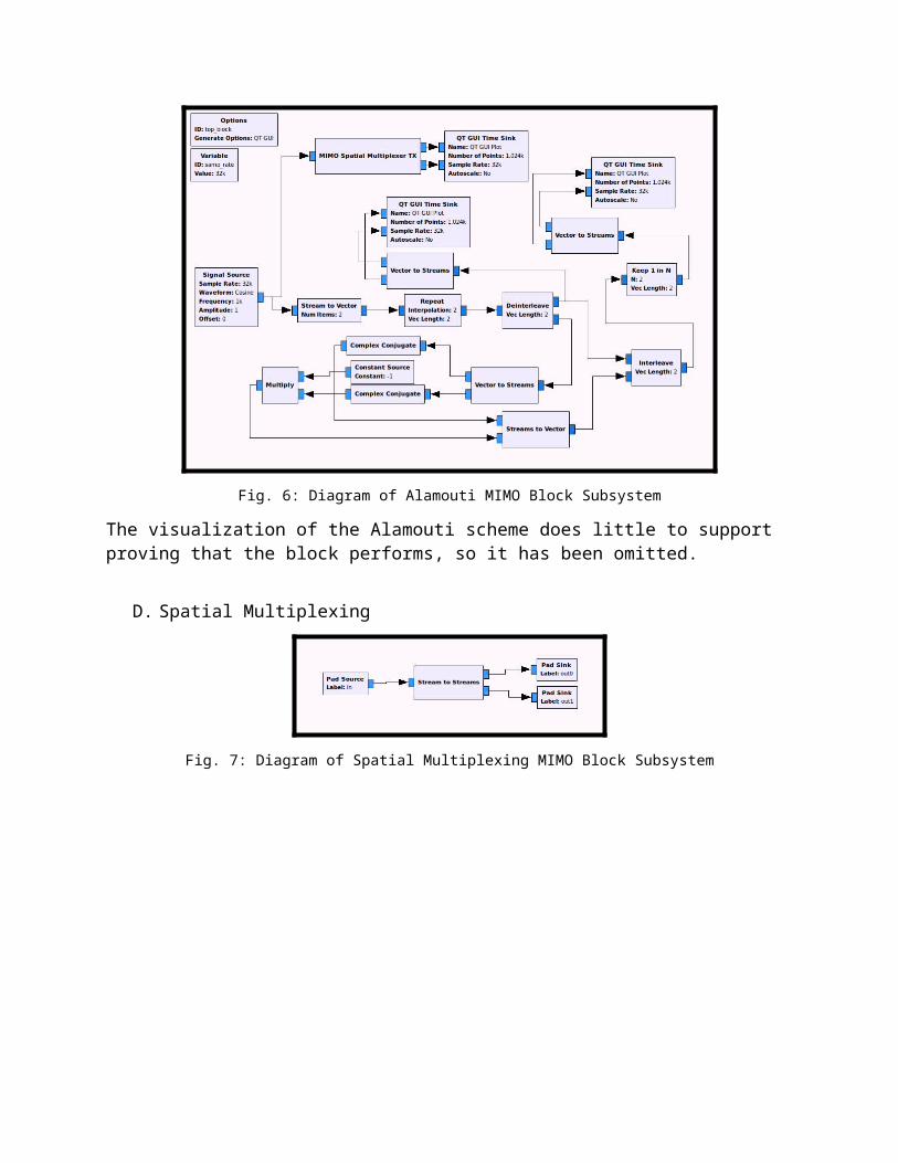
Fig.9: Diagram of Frequency Modulation Transmission Scheme for Over-The-Air Test
Fig.10: Diagram of Frequency Modulation Reception Scheme for Over-The-Air Test
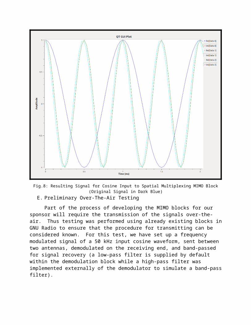
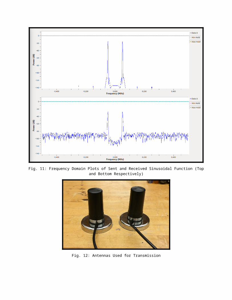
Fig. 11: Frequency Domain Plots of Sent and Received Sinusoidal Function (Top and Bottom Respectively)
Fig. 12: Antennas Used for Transmission

Fig. 13: Transmitter and Receiver SetupVI. Timeline and Future Plans12/15/14-1/19/15: Build and implement differential PSK
1/20/15-2/1/15: Build and implement differential MIMO (Alamouti)
2/2/215 - 2/16/15: Test hardware in different environments, investigate possible project extensions
4/22/15-5/1/15: Finalize results, write final report, and present at Senior Design Day
VII. BudgetSince the software that we are using for the project is open-source, it is free. The boards
that we are using for transmissions were also loaned to us(2 from Dr. Chandy, our advisor, and 2 from MITRE), therefore no budget was required.
VIII. ThanksOver the course of the semester, much has been done that should not go without noting.
That is, two sets of USRPs were given to us, one pair at the beginning of the semester, and the other in the few weeks before the final presentation. The second set of boards, modified and sent to us by MITRE, were quite temperamental when working with the computers that we have available. After much struggle, the boards were finally configured to our purposes and now function as designed. Thanks for this must go in part to our newly acquired junior team member Michael Williams.
IX. References[1] S. Zhou, “ECE 6152: Wireless Communication Handout (2x2 MIMO),” Oct. 2014.
[2] M. Filippi, “SDR Implementation of a OFDM-MIMO Receiver,” M.S. thesis, AAU, 2009.
[3] Longwei Liu; Hailin Zhang; Xiaofeng Lu; Yongzhao Li, "A differential Alamouti coding scheme for OFDM based asynchronous cooperative systems," Communication Software and Networks (ICCSN), 2011 IEEE 3rd International Conference on , vol., no., pp.51,56, 27-29 May 2011
[4] (2008). Lecture 7 - Modulation: Making the Message Fit the Medium. Available:http://ironbark.xtelco.com.au/subjects/DC/lectures/7/.
Related Documents


