ECE 442 Power Electronics 1 DC-DC Converter Drives • Principle of Power Control • Principle of Regenerative Brake Control • Principle of Rheostatic Brake Control • Combined Regenerative and Rheostatic Brake Control • Two and Four Quadrant DC – DC Converter Drives

ECE 442 Power Electronics1 DC-DC Converter Drives Principle of Power Control Principle of Regenerative Brake Control Principle of Rheostatic Brake Control.
Dec 21, 2015
Welcome message from author
This document is posted to help you gain knowledge. Please leave a comment to let me know what you think about it! Share it to your friends and learn new things together.
Transcript

ECE 442 Power Electronics 1
DC-DC Converter Drives
• Principle of Power Control
• Principle of Regenerative Brake Control
• Principle of Rheostatic Brake Control
• Combined Regenerative and Rheostatic Brake Control
• Two and Four Quadrant DC – DC Converter Drives

ECE 442 Power Electronics 2
Converter-fed DC Drive for a Separately-Excited Motor

ECE 442 Power Electronics 3
Waveform Summary Highly Inductive Load
Ripple-free Armature Current

ECE 442 Power Electronics 4
Principle of Power Control
• The average armature voltage is
• The power supplied to the motor is
sa kVV
asaao IkVIVP

ECE 442 Power Electronics 5
Principle of Power Control (continued)
• The average value of the input current is
• The equivalent input resistance seen by the source is
as kII
a
s
s
seq kI
V
I
VR
Control Power Flow by adjusting the duty cycle
ECE 442 Power Electronics 6
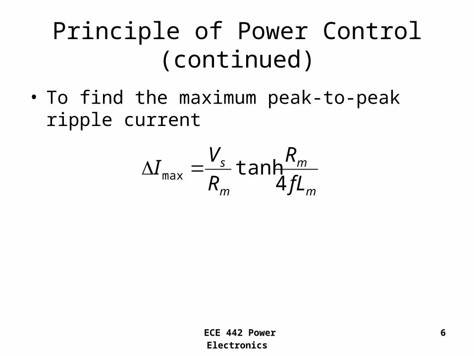
Principle of Power Control (continued)
• To find the maximum peak-to-peak ripple current
m
m
m
s
fL
R
R
VI
4tanhmax

ECE 442 Power Electronics 7
Example 15.7 A dc separately excited motor is powered by a dc-dc converter, as shown, from a 600V dc source. The armature resistance is Ra = 0.05Ω. The back emf constant is Kv = 1.527V/A rad/s. The average armature current is Ia = 250A. The field current is If = 2.5A. The armature current is continuous and has negligible ripple. If the duty cycle of the dc-dc converter is 60%, determine:

ECE 442 Power Electronics 8
Example 15.7 Solution
600
250
0.6
0.05
s
a
m a
V V
I A
k
R R
the input power from the source
(0.6)(600 )(250 ) 90o a a s a
o
P V I kV I
P V A kW
the equivalent input resistance of the dc-dc converter drive
1
6004
(250 )(0.6)
s seq
s a
eq
V VR
I I k
VR
A

ECE 442 Power Electronics 9
the motor speed
(0.6)(600 ) 360
360 (0.05 )(250 ) 347.5
347.591.03 /
(1.527 / / )(2.5 )
3091.03 869.3
g v f
g a m m
a s
g
g
v f
E K I
E V R I
V kV V V
E V A V
E Vrad s
K I V Arad s A
rpm
the developed torque
(1.527 / / )(250 )(2.5 ) 954.38
d t f a v f a
d
T K I I K I I
T V Arad s A A N m

ECE 442 Power Electronics 10
Application of a DC – DC Converter in Regenerative Braking

ECE 442 Power Electronics 11
Waveform SummaryArmature Current Continuous
and Ripple-Free

ECE 442 Power Electronics 12
Regenerative Braking
• Begin with the motor turning by kinetic energy of the vehicle
• Armature current flows as shown
• Turn the transistor on• Armature current rises• Turn the transistor off• Diode turns on, current
flows into the supply

ECE 442 Power Electronics 13
Principle of Regenerative Braking
• The average voltage across the transistor is
• The regenerated power can be found from
sch VkV )1(
)1( kVIP sag

ECE 442 Power Electronics 14
Principle of Regenerative Braking (continued)
• The voltage generated by the motor acting as a generator is
• The equivalent load resistance of the motor acting as a generator is
amsamchg
fvg
IRVkIRVE
IKE
)1(
ma
s
a
geq Rk
I
V
I
ER )1(
Control Power by changing k

ECE 442 Power Electronics 15max
max
max
min
min
min
)(0
fv
am
fv
s
samfv
fv
am
amfvg
samg
IK
IR
IK
V
VIRIK
IK
IR
IRIKE
VIRE
Minimum Braking Speed
Maximum Braking Speed

ECE 442 Power Electronics 16
Example 15.8 A dc-dc converter is used in regenerative braking of a dc series motor similar to the arrangement shown below. The dc supply voltage is 600V. The armature resistance is Ra = 0.02Ω and the field resistance is Rf = 0.03Ω. The back emf constant is Kv = 15.27mV/A rad/s. The average armature current is maintained constant at Ia = 250A. The armature current is continuous and has negligible ripple. If the duty cycle of the dc-dc converter is 60%, determine the following:
For this example, the field and armature need to be in series

ECE 442 Power Electronics 17
Example 15.8 Solution
600
250
0.01527 / /
0.6
s
a
v
m a f
V V
I A
K V Arad s
k
R R R
Determine the average voltage across the converter.
(1 )
(1 0.6)(600 ) 240ch s
ch
V k V
V V V
Determine the power regenerated to the dc supply
(1 )
(250 )(600 )(1 0.6) 60
g a s
g
P I V k
P A V kW
Determine the equivalent resistance of the motor acting as a generator
(1 )
0.02 0.03 0.05
600(1 0.6) 0.05 1.01
250
g seq m
a a
m a f
eq
E VR k R
I I
R R R
VR
A

ECE 442 Power Electronics 18
Determine the minimum permissible braking speed ωmin
min
min
0.05 2503.274 /
0.01527 / / 250
1 603.274 / 31.26
2 1min
m a
v f
R I Arad s
K I V Arad s A
rev srad s rpm
rad
Determine the maximum permissible braking speed ωmax
max
max
max
max
600 0.05
(0.01527 / / )(250 ) 0.01527 / /
160.445 /
30160.445 1532.14
s m a
v f v f
V R I
K I K I
V
V Arad s A V Arad s
rad s
rpm
Determine the motor speed
(1 ) 240 (0.05 )(250 ) 252.5
252.566.14 /
(0.01527 / / )(250 )
3066.14 631.6
gg v f
v f
g s m a
EE K I
K I
E k V R I V A V
Vrad s
V Arad s A
rpm

ECE 442 Power Electronics 19
Rheostatic Brake ControlDynamic Braking

ECE 442 Power Electronics 20
Waveform Summary

ECE 442 Power Electronics 21
Principle of Rheostatic Brake Control
• The average current in the braking resistor is
• The average voltage across the braking resistor is
)1( kII ab
)1( kIRV abb

ECE 442 Power Electronics 22
Principle of Rheostatic Brake Control (continued)
• The equivalent load resistance of the generator
• The power dissipated in the resistor Rb is
mba
beq RkR
I
VR )1(
)1(2 kRIP bab

ECE 442 Power Electronics 23
Example 15.9 A dc-dc converter is used in rheostatic braking of a dc separately excited motor as shown below. The armature resistance is Ra = 0.05Ω. The braking resistor is Rb = 5Ω. The back emf constant is Kv = 1.527V/A rad/s. The average armature current is maintained constant at Ia = 150A. The armature current is continuous and has negligible ripple. The field current is If = 1.5A. If the duty cycle of the dc-dc converter is 40%, determine:

ECE 442 Power Electronics 24
Example 15.9 Solution
150
1.527 / /
0.4
0.05
a
v
m a
I A
K V Arad s
k
R R
the average voltage across the dc-dc converter.
(1 )
(5 )(150 )(1 0.4) 450ch b b a
ch
V V R I k
V A V
the power dissipated in the braking resistor
2
2
(1 )
(150 ) (5 )(1 0.4) 67.5
b a b
b
P I R k
P A kW
the equivalent resistance of the motor acting as a generator
(1 )
(5 )(1 0.4) 0.05 3.05
beq b m
a
eq
VR R k R
I
R

ECE 442 Power Electronics 25
the motor speed ω
457.5199.74 /
(1.527 / / )(1.5 )
30199.74 1907.4
g v f
g
v f
E K I
E Vrad s
K I V Arad s A
rpm
the peak dc converter voltage
(150 )(5 ) 750
p a b
p
V I R
V A V

ECE 442 Power Electronics 26
Combined Regenerative and Rheostatic Brake Control

ECE 442 Power Electronics 27
Combined Regenerative and Rheostatic Brake Control (continued)
• Used when the supply is partly “receptive”
• Remove regenerative braking if line voltage is too high– Turn thyristor TR on
– Divert current to RB
– Apply rheostatic braking
– TR is “self-commutated”

ECE 442 Power Electronics 28
Two-Quadrant DC–DC Converter Drive

ECE 442 Power Electronics 29
Quadrant Operation Summary
Regenerative Braking Control Power Control

ECE 442 Power Electronics 30
Power Control
• Q1 and D2 operate
• Q1 ON, Vs applied to the motor
• Q1 turned OFF, D2 “free-wheels”
• Armature current decays

ECE 442 Power Electronics 31
Regenerative Control
• Q2 and D1 operate
• Q2 turned ON, motor acts as a generator, and the armature current rises
• Q2 turned OFF, motor returns energy to the supply via D1 “free-wheeling”

ECE 442 Power Electronics 32
Four Quadrant DC-DC Converter Drive

ECE 442 Power Electronics 33
Quadrant Operation Summary
Forward Regeneration Forward Power Control
Reverse Power Control Reverse Regeneration

ECE 442 Power Electronics 34
Forward Power Control
• Q1 and Q2 turned ON
• Supply voltage appears across the motor
• Armature current rises
• Q1 and Q2 turned OFF
• Armature current decays via D3 and D4

ECE 442 Power Electronics 35
Forward Regeneration
• Q1, Q2, and Q3 turned OFF
• Turn Q4 ON
• Armature current rises and flows through Q4, D2
• Q4 turned OFF, motor acts as a generator, returns energy back to the supply via D1, D2
ia reverses

ECE 442 Power Electronics 36
Reverse Power Control
• Q3 and Q4 turned ON• Supply voltage appears
in the reverse direction across the motor
• Armature current rises and flows in the reverse direction
• Q3 and Q4 turned OFF• Armature current
decays via D1 and D2
ia

ECE 442 Power Electronics 37
Reverse Regeneration
• Q1, Q3, Q4 turned OFF
• Q2 turned ON
• Armature current rises through Q2 and D4
• Q2 turned OFF
• Armature current falls and returns energy via D3 and D4
i a
Related Documents