ECE 3567 Microcontrollers Lab Autumn 2019 Dr. Gregg Chapman Laboratory #3 – Pulse Width Modulation & RGB LED 1

Welcome message from author
This document is posted to help you gain knowledge. Please leave a comment to let me know what you think about it! Share it to your friends and learn new things together.
Transcript

ECE 3567 Microcontrollers Lab
Autumn 2019Dr. Gregg Chapman
Laboratory #3 – Pulse Width Modulation & RGB LED
1
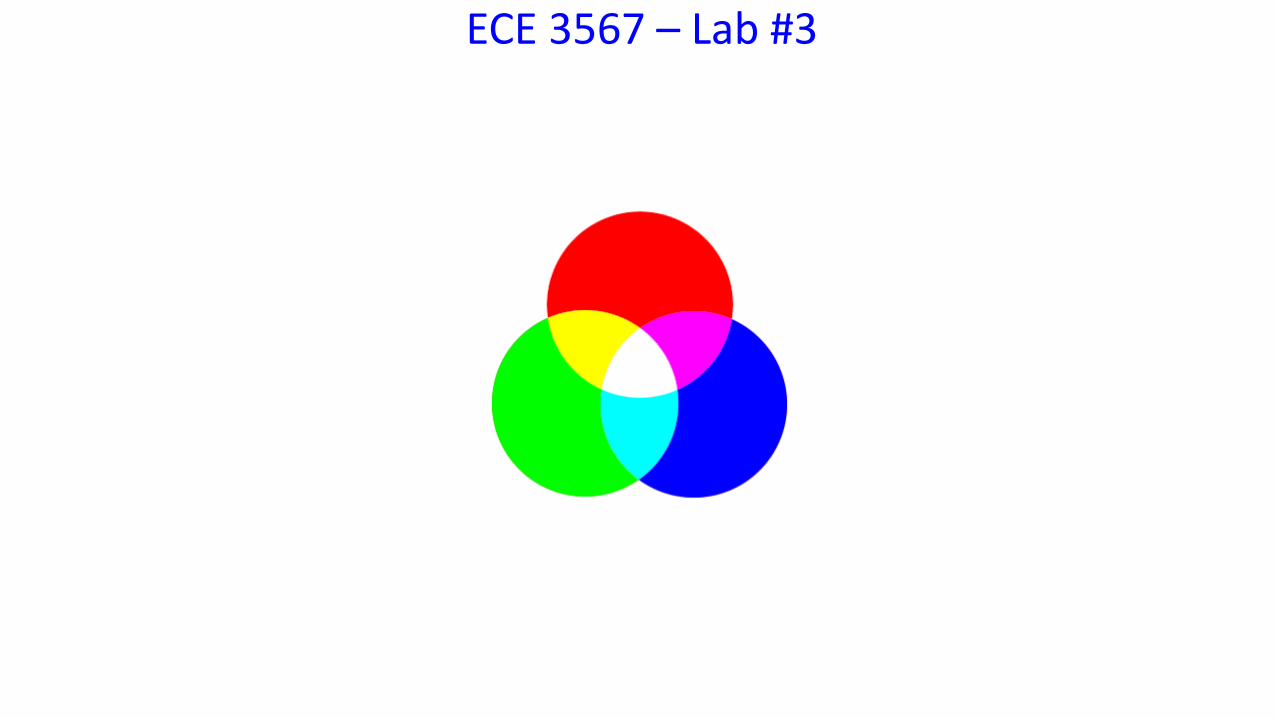
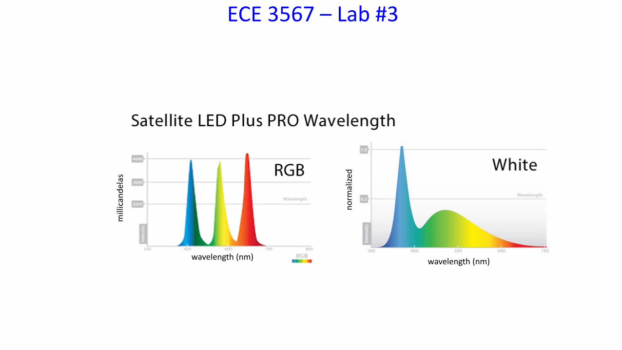
ECE 3567 – Lab #3
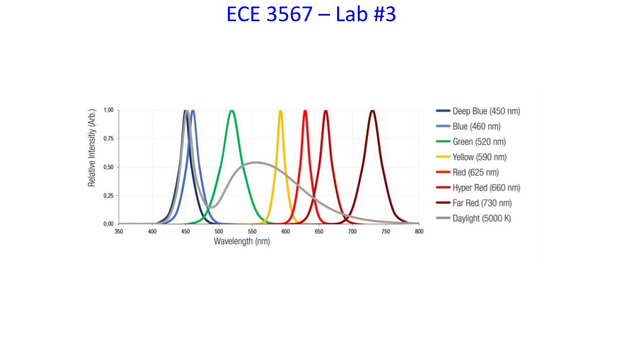
ECE 3567 – Lab #3
ECE 3567 – Lab #3
wavelength (nm) wavelength (nm)
mill
ican
dela
s
norm
alize
d
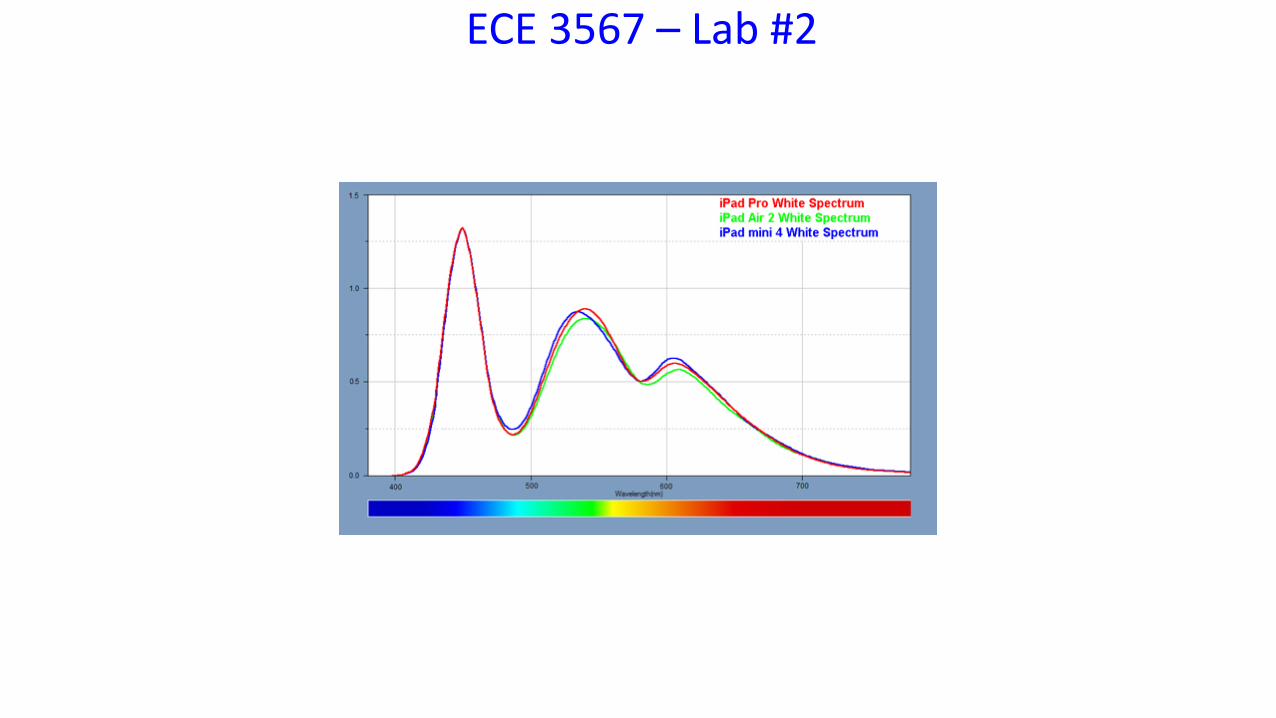
ECE 3567 – Lab #2

Quiz #2 Material
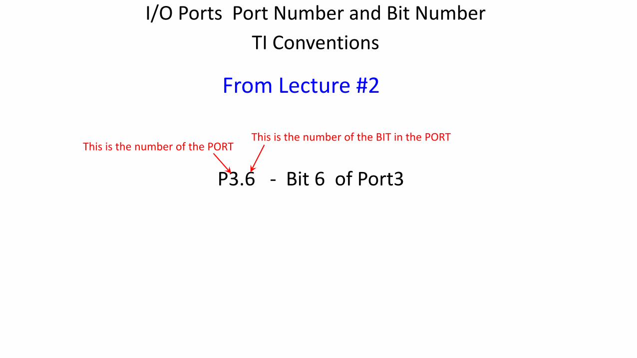
I/O Ports Port Number and Bit NumberTI Conventions
P3.6 - Bit 6 of Port3
This is the number of the PORTThis is the number of the BIT in the PORT
From Lecture #2
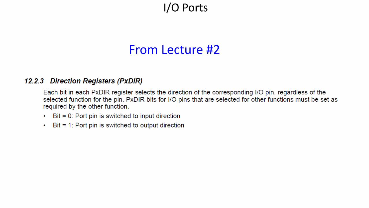
I/O Ports
From Lecture #2
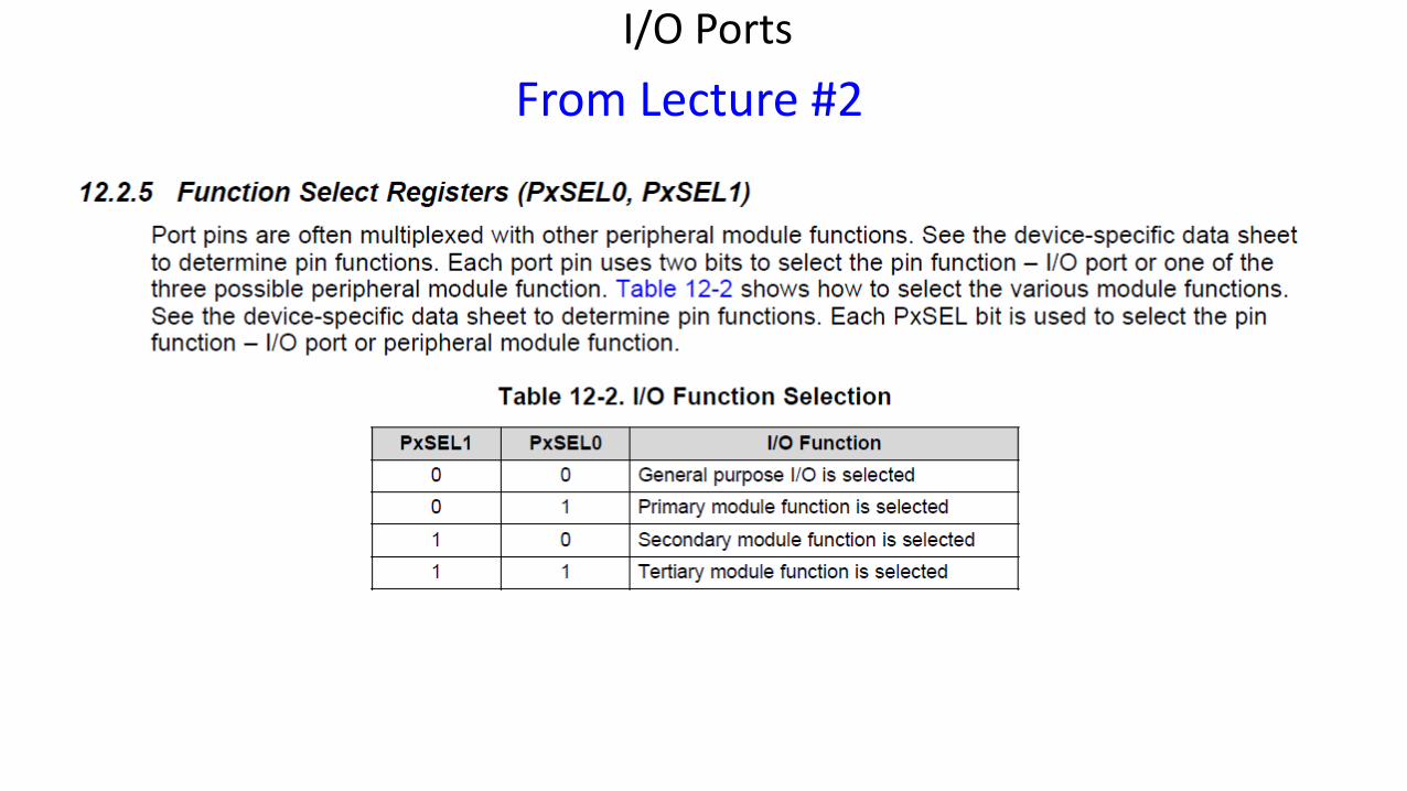
I/O PortsFrom Lecture #2
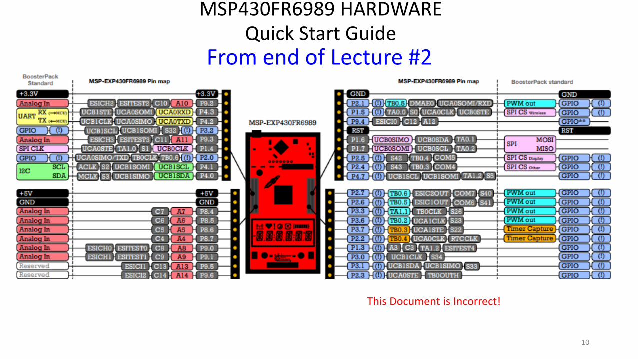
MSP430FR6989 HARDWAREQuick Start Guide
10
From end of Lecture #2
This Document is Incorrect!
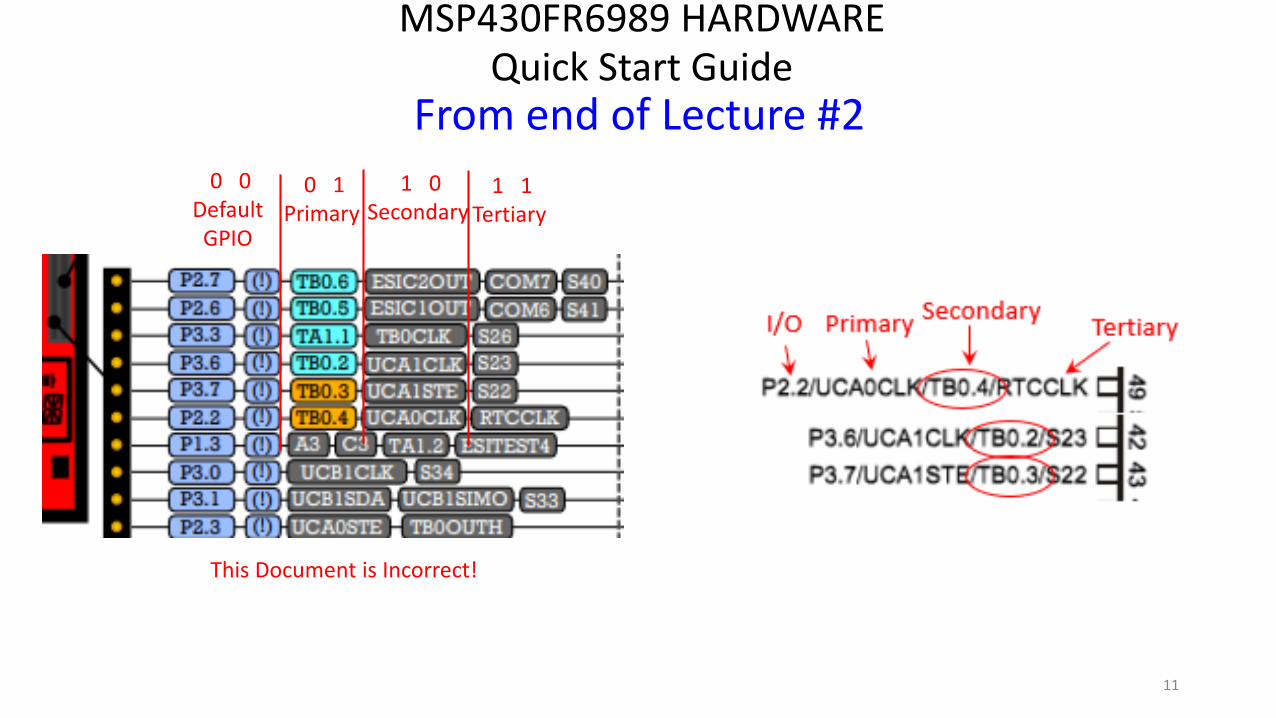
MSP430FR6989 HARDWAREQuick Start Guide
11
From end of Lecture #2
This Document is Incorrect!
0 0 DefaultGPIO
1 0 Secondary
0 1Primary
1 1 Tertiary
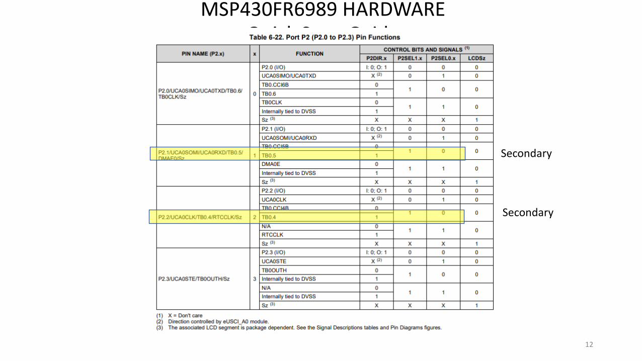
MSP430FR6989 HARDWAREQuick Start Guide
FOR LAB #3
12
Secondary
Secondary
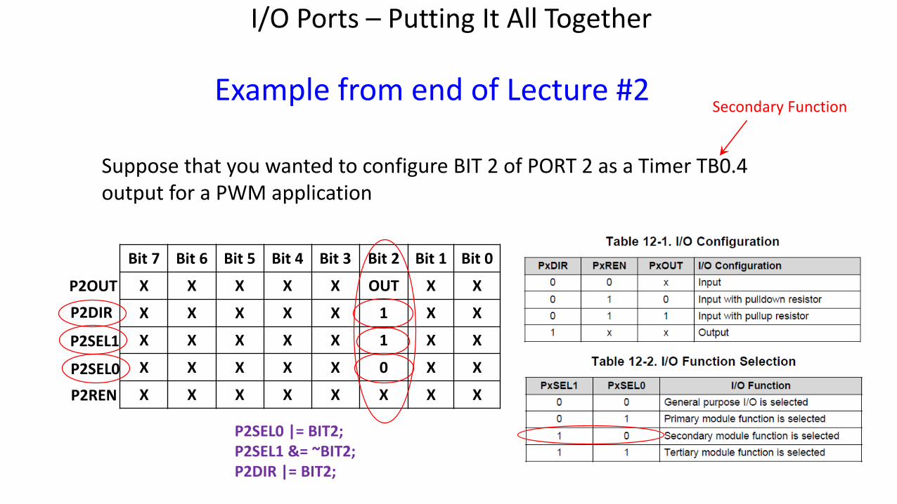
I/O Ports – Putting It All Together
Bit 7 Bit 6 Bit 5 Bit 4 Bit 3 Bit 2 Bit 1 Bit 0
X X X X X OUT X X
X X X X X 1 X X
X X X X X 1 X X
X X X X X 0 X X
X X X X X X X XP2SEL0
P2SEL1
P2DIR
P2OUT
P2REN
Suppose that you wanted to configure BIT 2 of PORT 2 as a Timer TB0.4 output for a PWM application
Example from end of Lecture #2Secondary Function
P2SEL0 |= BIT2;P2SEL1 &= ~BIT2;P2DIR |= BIT2;
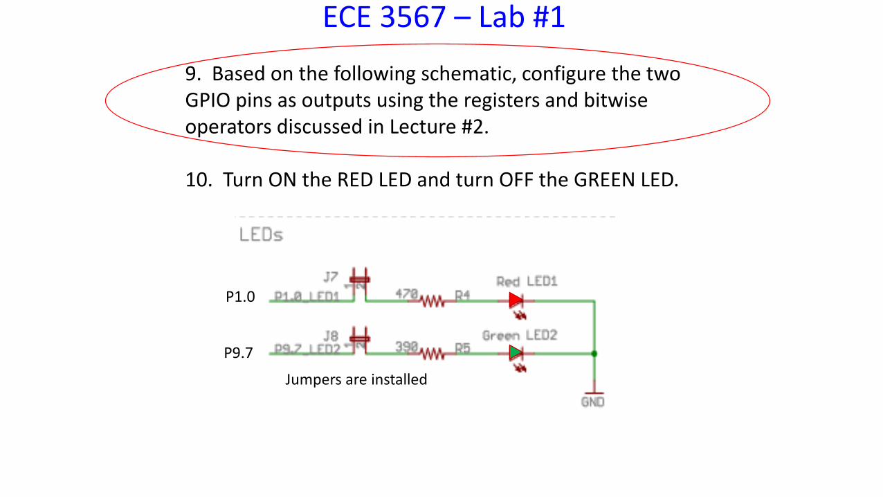
ECE 3567 – Lab #1
9. Based on the following schematic, configure the two GPIO pins as outputs using the registers and bitwise operators discussed in Lecture #2.
10. Turn ON the RED LED and turn OFF the GREEN LED.
P1.0
P9.7
Jumpers are installed
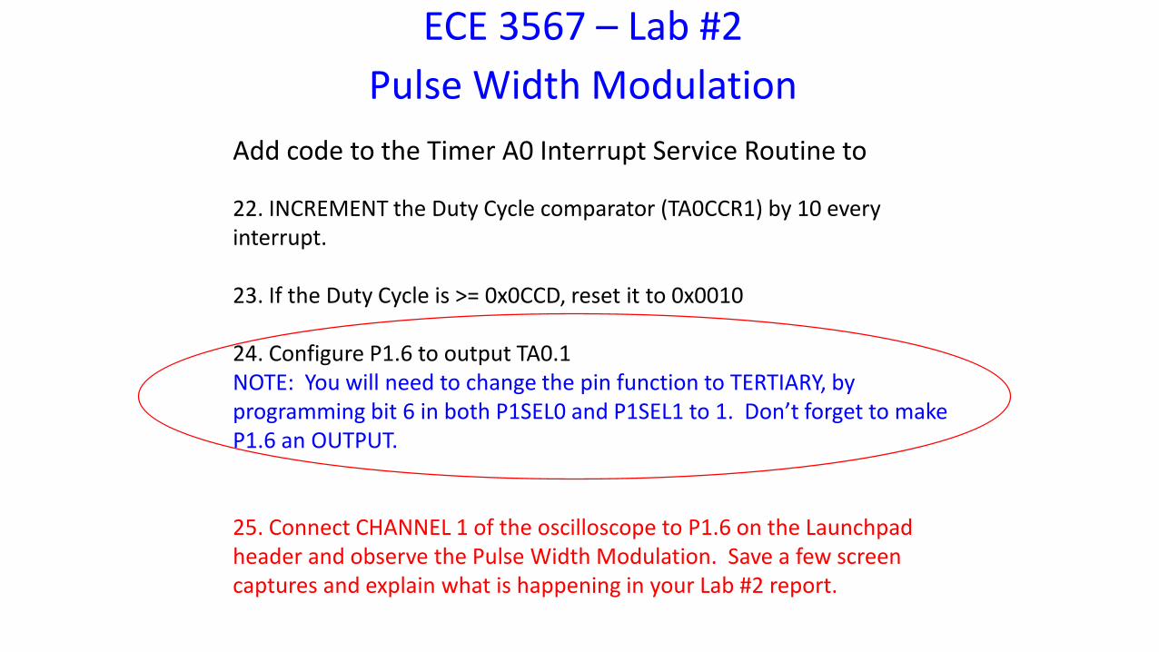
ECE 3567 – Lab #2Pulse Width Modulation
Add code to the Timer A0 Interrupt Service Routine to
22. INCREMENT the Duty Cycle comparator (TA0CCR1) by 10 every interrupt.
23. If the Duty Cycle is >= 0x0CCD, reset it to 0x0010
24. Configure P1.6 to output TA0.1NOTE: You will need to change the pin function to TERTIARY, by programming bit 6 in both P1SEL0 and P1SEL1 to 1. Don’t forget to make P1.6 an OUTPUT.
25. Connect CHANNEL 1 of the oscilloscope to P1.6 on the Launchpad header and observe the Pulse Width Modulation. Save a few screen captures and explain what is happening in your Lab #2 report.
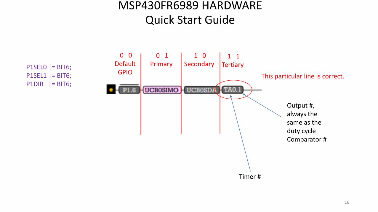
MSP430FR6989 HARDWAREQuick Start Guide
16
0 0 DefaultGPIO
1 0 Secondary
0 1Primary
1 1 Tertiary
Output #, always the same as the duty cycle Comparator #
Timer #
P1SEL0 |= BIT6;P1SEL1 |= BIT6;P1DIR |= BIT6;
This particular line is correct.
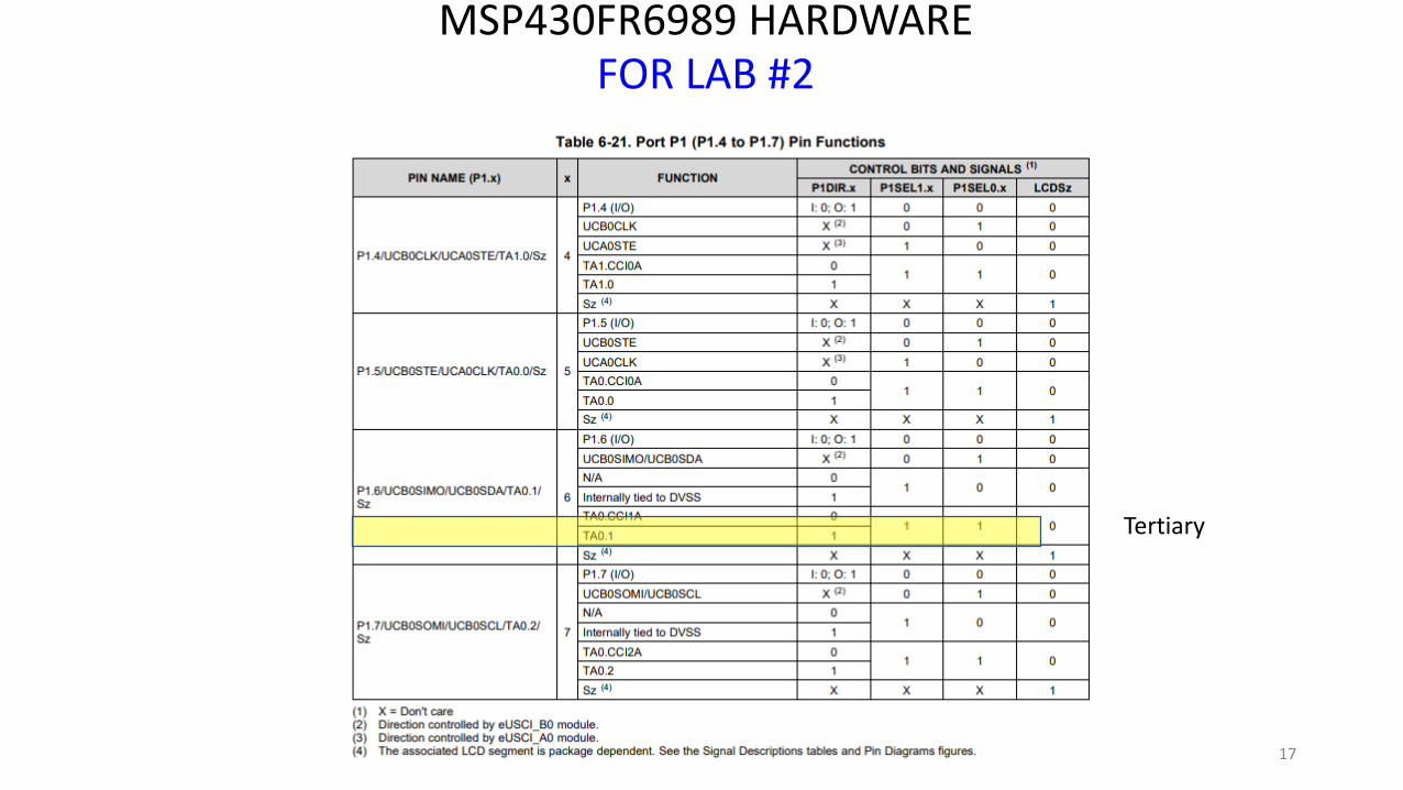
MSP430FR6989 HARDWAREFOR LAB #2
17
Tertiary

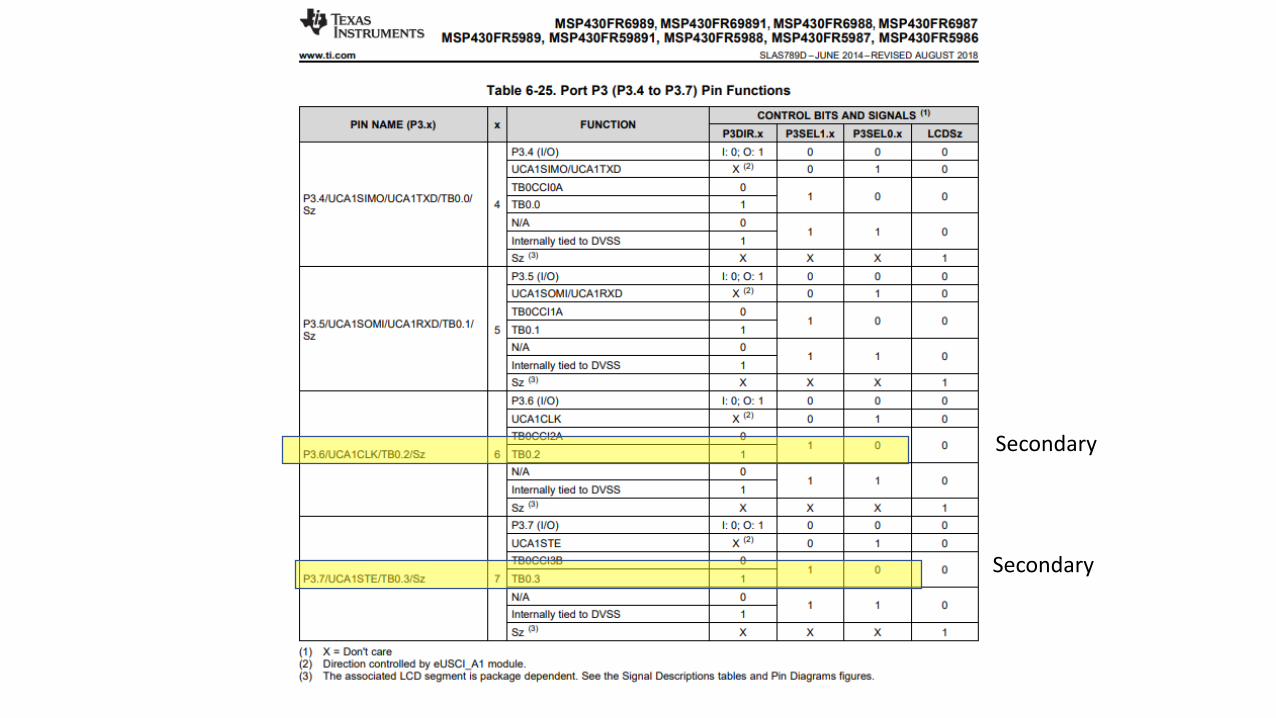
MSP430FR6989 HARDWAREQuick Start Guide
FOR LAB #3
18
Secondary
Secondary
MSP430FR6989 HARDWAREQuick Start Guide
FOR LAB #3
Secondary
Secondary
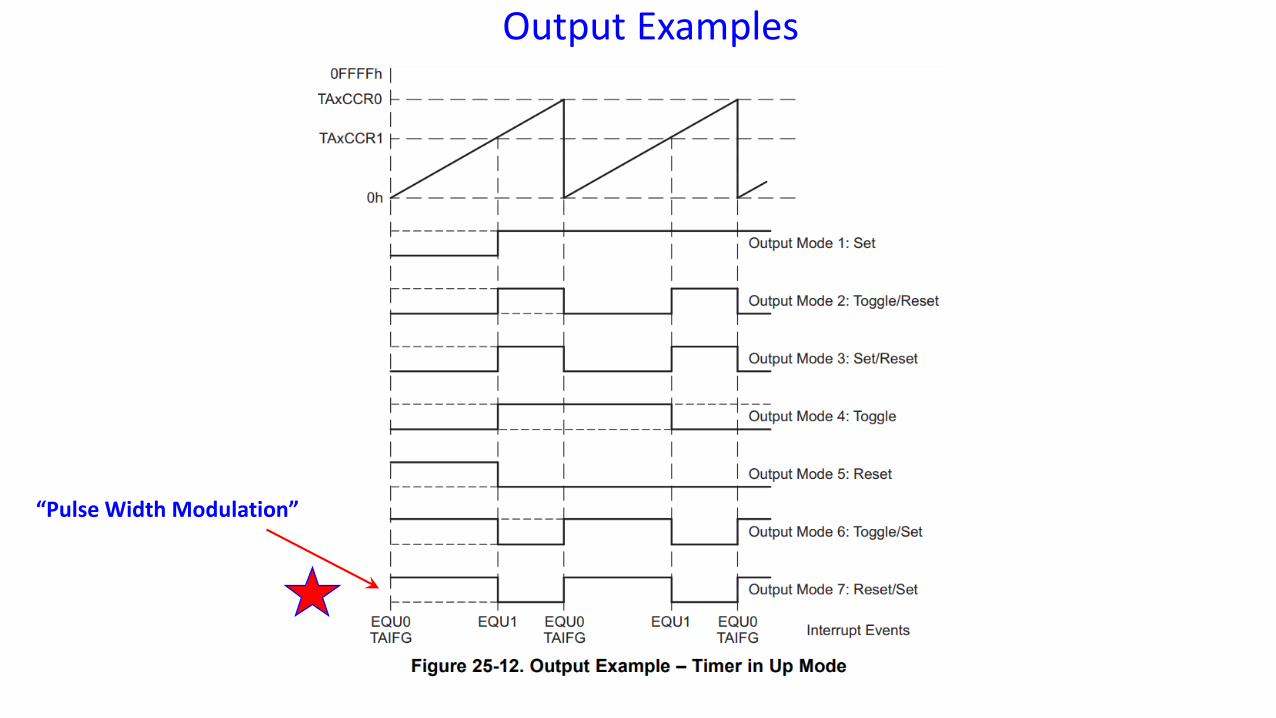
Output Examples
“Pulse Width Modulation”
QUIZZES
• Quizzes will be ONLINE in CARMEN for the rest of course.
• You may take the quiz any time BEFORE or AFTER the Lab, up until MIDNIGHT on the final day of each lab (second week).
• 5 MULTIPLE CHOICE questions are chosen at random from 20 possible questions. Each question is worth 1 point.
• There is a 30-minute time limit for each attempt.
• You may retake the quiz ONE TIME.
• Grades are recorded automatically.
• There is NO PARTIAL CREDIT.
Laboratory #3
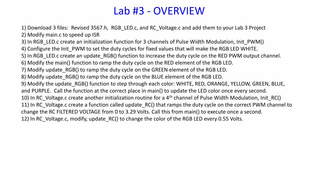
Lab #3 - OVERVIEW1) Download 3 files: Revised 3567.h, RGB_LED.c, and RC_Voltage.c and add them to your Lab 3 Project2) Modify main.c to speed up ISR3) In RGB_LED.c create an initialization function for 3 channels of Pulse Width Modulation, Init_PWM()4) Configure the Init_PWM to set the duty cycles for fixed values that will make the RGB LED WHITE.5) In RGB_LED.c create an update_RGB() function to increase the duty cycle on the RED PWM output channel.6) Modify the main() function to ramp the duty cycle on the RED element of the RGB LED.7) Modify update_RGB() to ramp the duty cycle on the GREEN element of the RGB LED.8) Modify update_RGB() to ramp the duty cycle on the BLUE element of the RGB LED.9) Modify the update_RGB() function to step through each color: WHITE, RED, ORANGE, YELLOW, GREEN, BLUE, and PURPLE. Call the function at the correct place in main() to update the LED color once every second.10) In RC_Voltage.c create another initialization routine for a 4th channel of Pulse Width Modulation, Init_RC()11) In RC_Voltage.c create a function called update_RC() that ramps the duty cycle on the correct PWM channel to change the RC FILTERED VOLTAGE from 0 to 3.29 Volts. Call this from main() to execute once a second.12) In RC_Voltage.c, modify, update_RC() to change the color of the RGB LED every 0.55 Volts.
ECE 3567 – Lab #3
Part 1Clean-up main()
ECE 3567 – Lab #3Additional Files Needed
1. Download the Lab3.zip under Lab 3 on the ECE 3567 website and add the UPDATED ECE3567.h, RGB_LED.c, and RC_Voltage.c to your Lab 3 project.
ECE 3567 – Lab #3ISR Changes
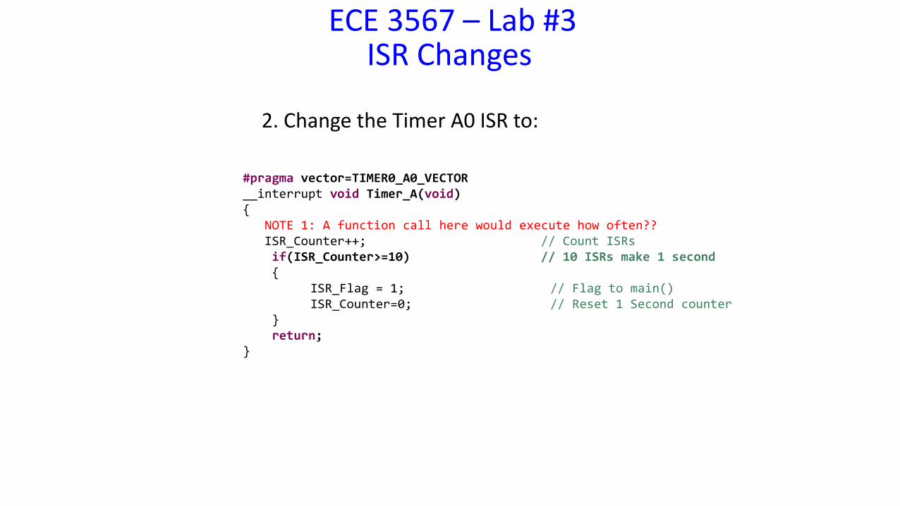
2. Change the Timer A0 ISR to:
#pragma vector=TIMER0_A0_VECTOR__interrupt void Timer_A(void){
NOTE 1: A function call here would execute how often??ISR_Counter++; // Count ISRsif(ISR_Counter>=10) // 10 ISRs make 1 second{
ISR_Flag = 1; // Flag to main()ISR_Counter=0; // Reset 1 Second counter
}return;
}
ECE 3567 – Lab #3main() Changes
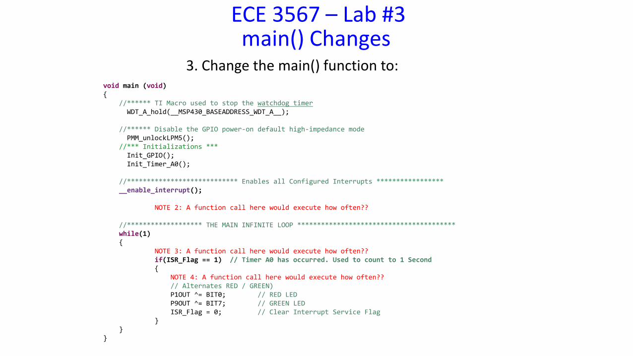
3. Change the main() function to:void main (void){
//****** TI Macro used to stop the watchdog timerWDT_A_hold(__MSP430_BASEADDRESS_WDT_A__);
//****** Disable the GPIO power-on default high-impedance modePMM_unlockLPM5();
//*** Initializations ***Init_GPIO();Init_Timer_A0();
//**************************** Enables all Configured Interrupts *****************__enable_interrupt();
NOTE 2: A function call here would execute how often??
//******************* THE MAIN INFINITE LOOP ****************************************while(1){
NOTE 3: A function call here would execute how often??if(ISR_Flag == 1) // Timer A0 has occurred. Used to count to 1 Second{
NOTE 4: A function call here would execute how often??// Alternates RED / GREEN)P1OUT ^= BIT0; // RED LEDP9OUT ^= BIT7; // GREEN LEDISR_Flag = 0; // Clear Interrupt Service Flag
}}
}
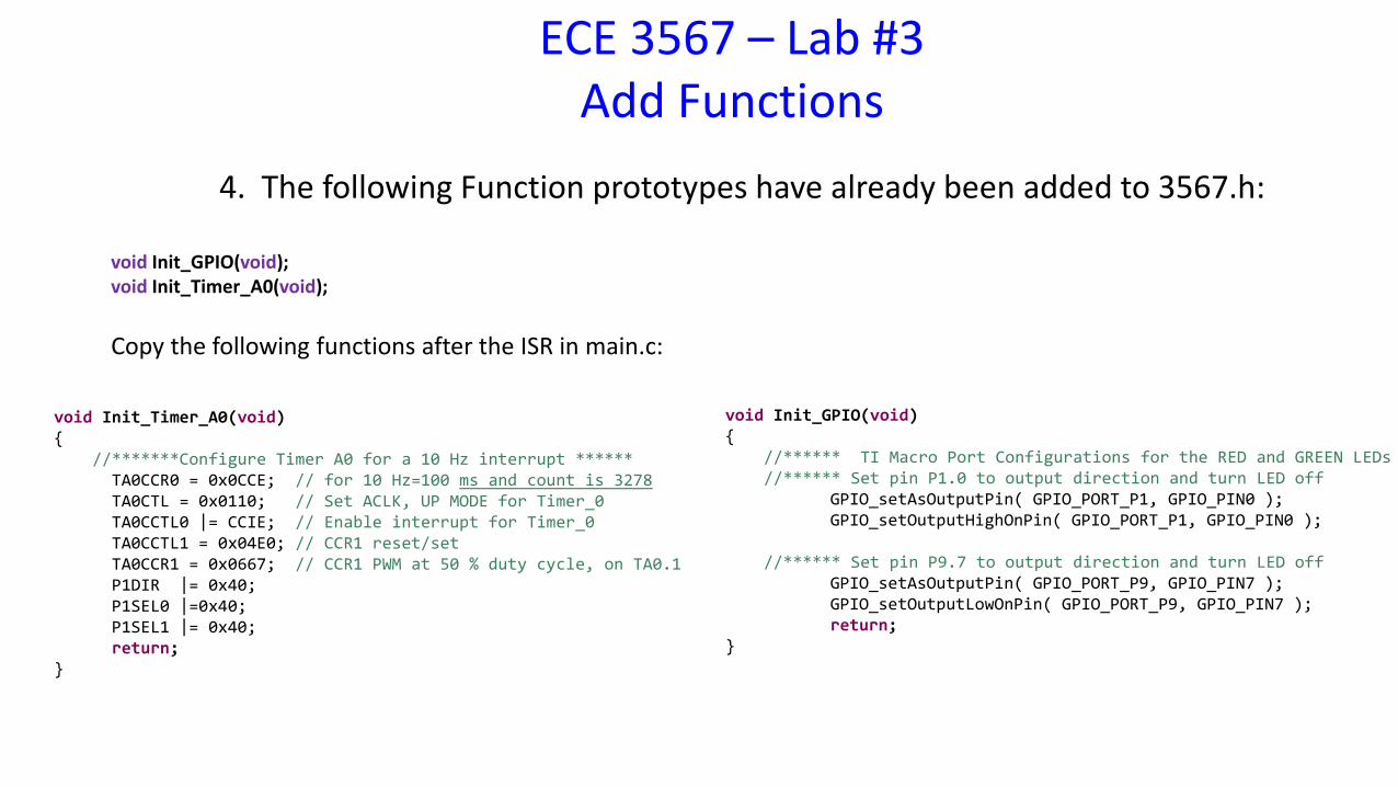
4. The following Function prototypes have already been added to 3567.h:
void Init_GPIO(void);void Init_Timer_A0(void);
Copy the following functions after the ISR in main.c:
void Init_Timer_A0(void){
//*******Configure Timer A0 for a 10 Hz interrupt ******TA0CCR0 = 0x0CCE; // for 10 Hz=100 ms and count is 3278TA0CTL = 0x0110; // Set ACLK, UP MODE for Timer_0TA0CCTL0 |= CCIE; // Enable interrupt for Timer_0TA0CCTL1 = 0x04E0; // CCR1 reset/setTA0CCR1 = 0x0667; // CCR1 PWM at 50 % duty cycle, on TA0.1P1DIR |= 0x40;P1SEL0 |=0x40;P1SEL1 |= 0x40;return;
}
void Init_GPIO(void){
//****** TI Macro Port Configurations for the RED and GREEN LEDs//****** Set pin P1.0 to output direction and turn LED off
GPIO_setAsOutputPin( GPIO_PORT_P1, GPIO_PIN0 ); GPIO_setOutputHighOnPin( GPIO_PORT_P1, GPIO_PIN0 );
//****** Set pin P9.7 to output direction and turn LED offGPIO_setAsOutputPin( GPIO_PORT_P9, GPIO_PIN7 );GPIO_setOutputLowOnPin( GPIO_PORT_P9, GPIO_PIN7 );return;
}
ECE 3567 – Lab #3Add Functions
ECE 3567 – Lab #3
Checkpoint #1: Demonstrate that your Lab #3 Project operates identically to Lab #2 AFTER making any changes to main.c, and UPDATING the 3567.h file.
ECE 3567 – Lab #3
Part 2Timer B0 Initialization,
RGB LED PWM Initialization& the WHITE LED
ECE 3567 – Lab #3Part 2
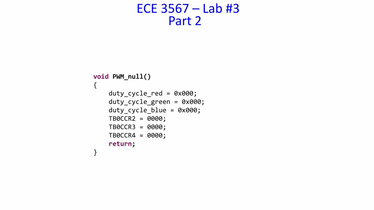
void PWM_null() {
duty_cycle_red = 0x000;duty_cycle_green = 0x000;duty_cycle_blue = 0x000;TB0CCR2 = 0000; TB0CCR3 = 0000; TB0CCR4 = 0000; return;
}
ECE 3567 – Lab #3Part 2
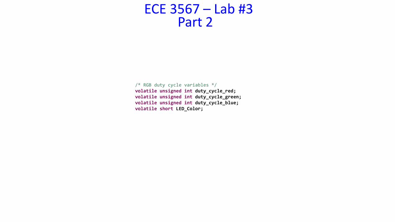
/* RGB duty cycle variables */volatile unsigned int duty_cycle_red;volatile unsigned int duty_cycle_green;volatile unsigned int duty_cycle_blue;volatile short LED_Color;
ECE 3567 – Lab #3Part 2
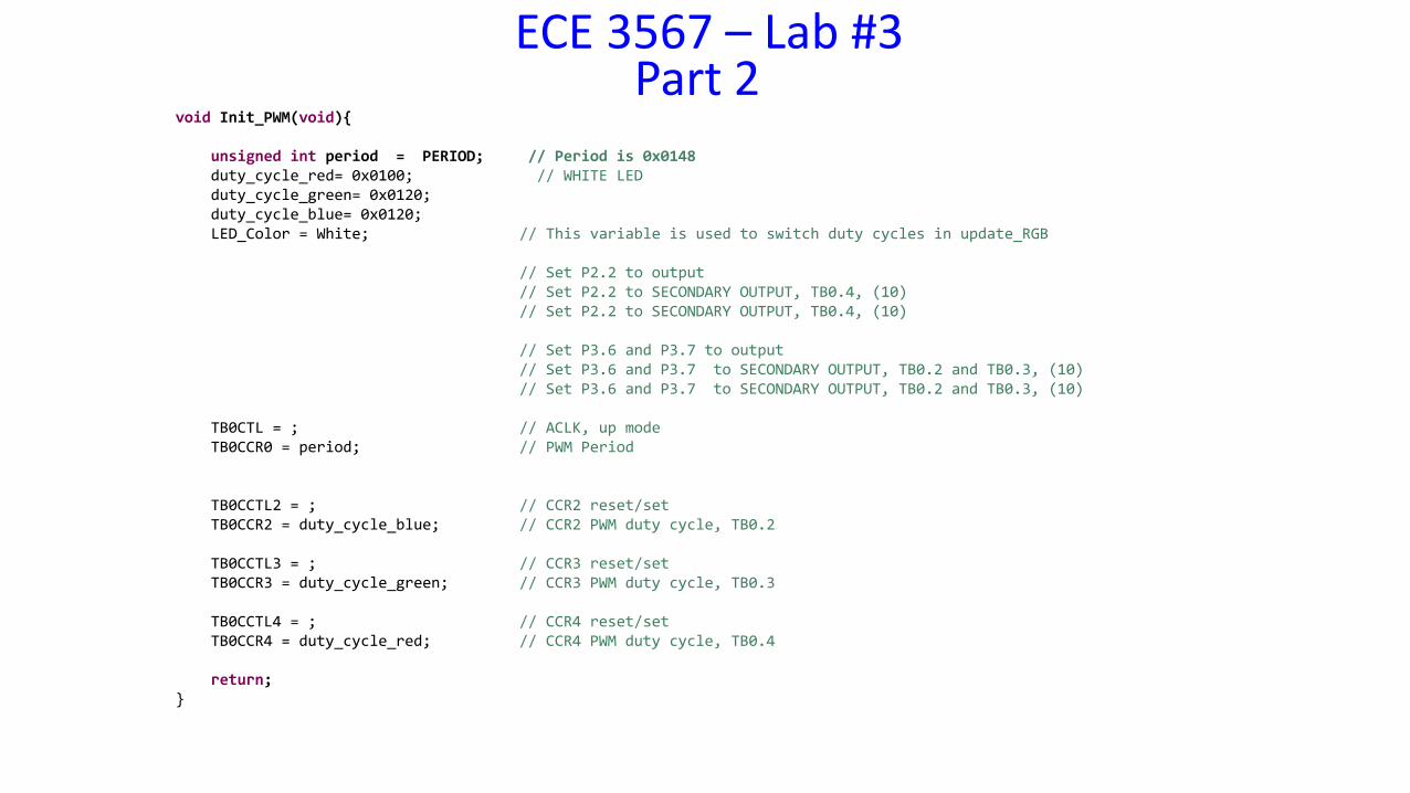
void Init_PWM(void){
unsigned int period = PERIOD; // Period is 0x0148duty_cycle_red= 0x0100; // WHITE LEDduty_cycle_green= 0x0120;duty_cycle_blue= 0x0120;LED_Color = White; // This variable is used to switch duty cycles in update_RGB
// Set P2.2 to output// Set P2.2 to SECONDARY OUTPUT, TB0.4, (10)// Set P2.2 to SECONDARY OUTPUT, TB0.4, (10)
// Set P3.6 and P3.7 to output// Set P3.6 and P3.7 to SECONDARY OUTPUT, TB0.2 and TB0.3, (10)// Set P3.6 and P3.7 to SECONDARY OUTPUT, TB0.2 and TB0.3, (10)
TB0CTL = ; // ACLK, up modeTB0CCR0 = period; // PWM Period
TB0CCTL2 = ; // CCR2 reset/setTB0CCR2 = duty_cycle_blue; // CCR2 PWM duty cycle, TB0.2
TB0CCTL3 = ; // CCR3 reset/setTB0CCR3 = duty_cycle_green; // CCR3 PWM duty cycle, TB0.3
TB0CCTL4 = ; // CCR4 reset/setTB0CCR4 = duty_cycle_red; // CCR4 PWM duty cycle, TB0.4
return;}
ECE 3567 – Lab #3
Checkpoint #2: Display your WHITE LED to the Lab Monitors
ECE 3567 – Lab #3
Part 3Ramp Each Element of the
RGB LED
ECE 3567 – Lab #3Part 3
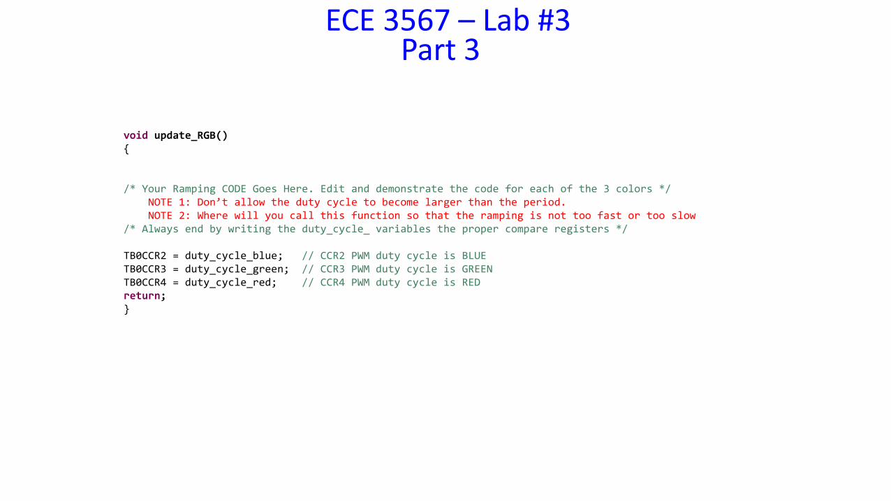
void update_RGB(){
/* Your Ramping CODE Goes Here. Edit and demonstrate the code for each of the 3 colors */NOTE 1: Don’t allow the duty cycle to become larger than the period.NOTE 2: Where will you call this function so that the ramping is not too fast or too slow
/* Always end by writing the duty_cycle_ variables the proper compare registers */
TB0CCR2 = duty_cycle_blue; // CCR2 PWM duty cycle is BLUETB0CCR3 = duty_cycle_green; // CCR3 PWM duty cycle is GREENTB0CCR4 = duty_cycle_red; // CCR4 PWM duty cycle is REDreturn;}
ECE 3567 – Lab #3
Checkpoint #3: Display your RED GREEN and BLUE duty cycle ramping code to the Lab Monitors.
ECE 3567 – Lab #3
Part 4Change the RGB LED Color
ECE 3567 – Lab #3Part 4 - Change the RGB LED Color
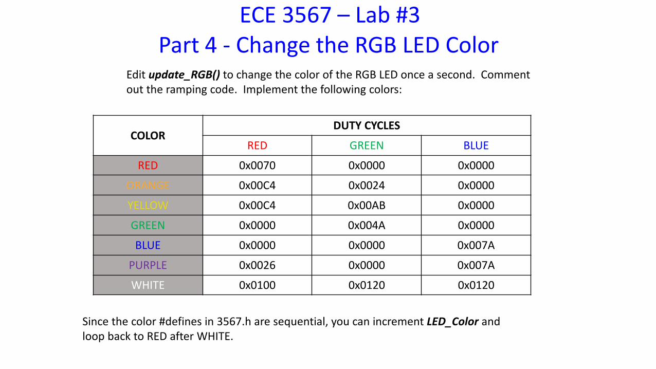
Edit update_RGB() to change the color of the RGB LED once a second. Comment out the ramping code. Implement the following colors:
COLORDUTY CYCLES
RED GREEN BLUE
RED 0x0070 0x0000 0x0000
ORANGE 0x00C4 0x0024 0x0000
YELLOW 0x00C4 0x00AB 0x0000
GREEN 0x0000 0x004A 0x0000
BLUE 0x0000 0x0000 0x007A
PURPLE 0x0026 0x0000 0x007A
WHITE 0x0100 0x0120 0x0120
Since the color #defines in 3567.h are sequential, you can increment LED_Color and loop back to RED after WHITE.
ECE 3567 – Lab #3
Checkpoint #4: Display your update_RGB function to change colors every 1 second to the Lab Monitors
ECE 3567 – Lab #3
Part 5Initialize and Ramp the RC
Voltage
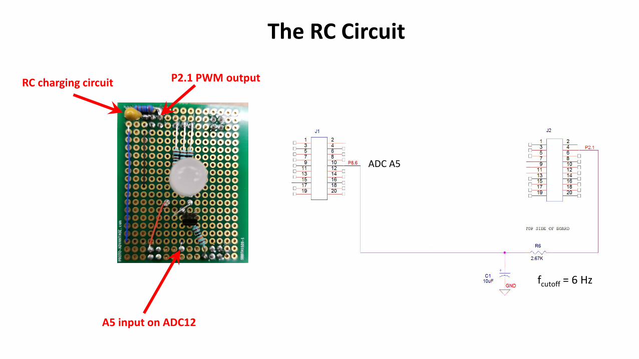
The RC Circuit
fcutoff = 6 Hz
ADC A5
A5 input on ADC12
RC charging circuit P2.1 PWM output
ECE 3567 – Lab #3Part 5 - Ramp the RC Voltage
Given that TB0.5 is the SECONDARY function on pin P2.1, write the code to initialize the PWM channel to the RC time constant.
Call the function Init_RC()
The function should be in the RC_Voltage.c file.
NOTE: The xxxx.c files DO NOT require a #include to be compiled and linked in the project.
Add the function call to the beginning of main().
ECE 3567 – Lab #3Part 5 - Ramp the RC Voltage
Write a function to increment the RC Voltage PWM and use it to ramp the RC Voltage from 0 to the value that sets the voltage to 3.29 V. Determine this value experimentally.
Increment the duty cycle by a step size that results in a 10 millivolt change in the RC Voltage. Determine this value experimentally.
Call the function update_RC()
The function should be in the RC_Voltage.c file.
Call the function in main() so that it executes once per second.
ECE 3567 – Lab #3
Checkpoint #5: Display your update_RC() function to the Lab Monitors using a Digital Multi-meter to measure voltage.
ECE 3567 – Lab #3
Part 6Change the LED Color based
on RC Voltage Output
ECE 3567 – Lab #3Part 6
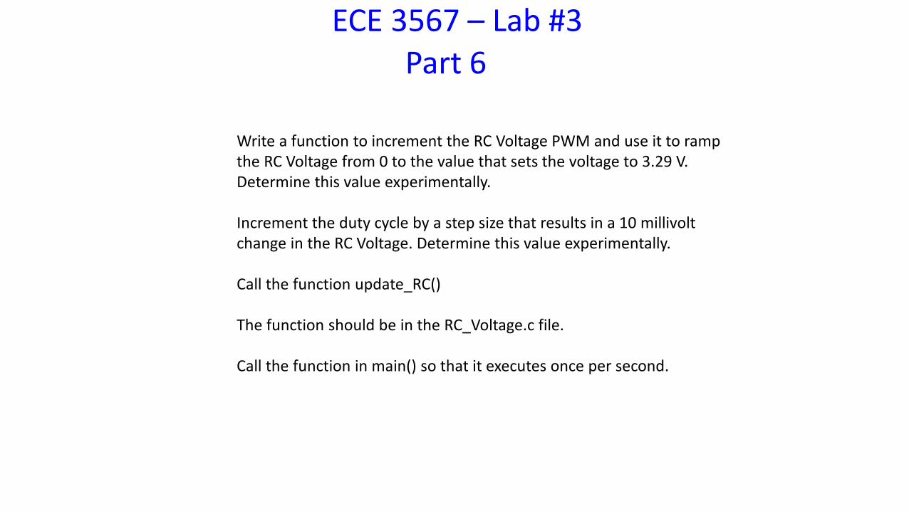
Write a function to increment the RC Voltage PWM and use it to ramp the RC Voltage from 0 to the value that sets the voltage to 3.29 V. Determine this value experimentally.
Increment the duty cycle by a step size that results in a 10 millivolt change in the RC Voltage. Determine this value experimentally.
Call the function update_RC()
The function should be in the RC_Voltage.c file.
Call the function in main() so that it executes once per second.
ECE 3567 – Lab #3Part 6 – Indicate the Voltage Range with the LED
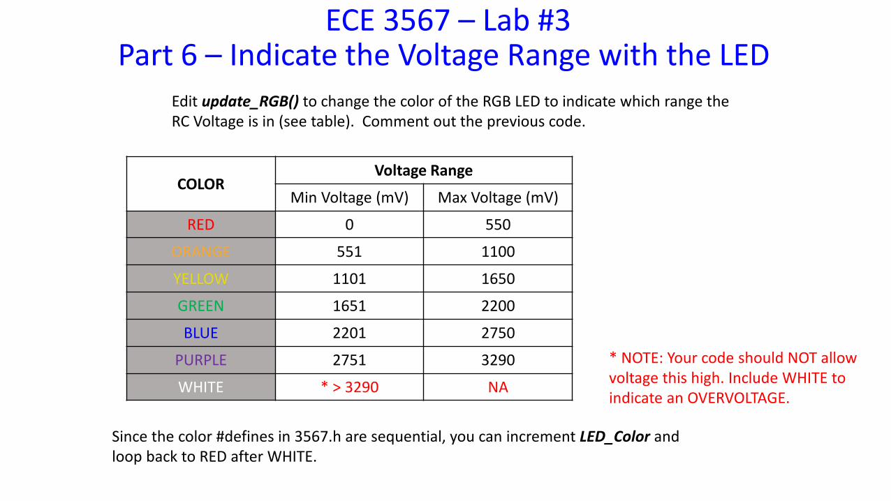
Edit update_RGB() to change the color of the RGB LED to indicate which range the RC Voltage is in (see table). Comment out the previous code.
COLORVoltage Range
Min Voltage (mV) Max Voltage (mV)
RED 0 550
ORANGE 551 1100
YELLOW 1101 1650
GREEN 1651 2200
BLUE 2201 2750
PURPLE 2751 3290
WHITE * > 3290 NA
Since the color #defines in 3567.h are sequential, you can increment LED_Color and loop back to RED after WHITE.
* NOTE: Your code should NOT allow voltage this high. Include WHITE to indicate an OVERVOLTAGE.
ECE 3567 – Lab #3Part 6 – Indicate the Voltage Range with the LED
IN Lab #4 you will measure the RC Voltage using the Analog to Digital Converter. In Lab 3, you must base the LED color on the value that you are writing to the duty cycle register.
ECE 3567 – Lab #3
Checkpoint #6: Demonstrate your MODIFIED update_RC() function that changes the LED color every 550 mV as the RC Voltage ramps up.
ECE 3567 – Lab #3
End of Laboratory #3
Related Documents