ECE 331 – Digital System Design Course Introduction and VHDL Fundamentals (Lecture #1)

ECE 331 – Digital System Design Course Introduction and VHDL Fundamentals (Lecture #1)
Dec 21, 2015
Welcome message from author
This document is posted to help you gain knowledge. Please leave a comment to let me know what you think about it! Share it to your friends and learn new things together.
Transcript
ECE 331 – Digital System Design
Course Introductionand
VHDL Fundamentals
(Lecture #1)
ECE 331 - Digital System Design 2
Course Introduction
(see Syllabus)

ECE 331 - Digital System Design 3
Expectations

ECE 331 - Digital System Design 4
I (Dr. Lorie) am expected to:
1.Properly prepare for each lecture.
2.Attend every class.
3.Do my best to teach the material so that the students learn and understand it.
4.Be available during office hours and other scheduled meeting times to answer questions.
5.Give exams that fairly test the students on the material taught in the class.

ECE 331 - Digital System Design 5
You (the student) are expected to:
1.Attend class.
2.Spend a minimum of 9 hours each week outside of class learning the material.
3.Read the text book.
4.Do the homework.
5.Attend the lab and complete all of the lab experiments.
ECE 331 - Digital System Design 6
Questions?
ECE 331 - Digital System Design 7
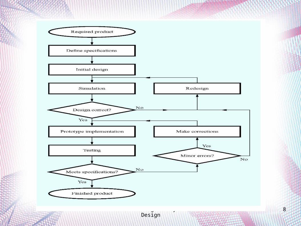
The Design Process
ECE 331 - Digital System Design 8

ECE 331 - Digital System Design 9

ECE 331 - Digital System Design 10
Design conception
VHDLSchematic capture
DESIGN ENTRY
Design correct?
Functional simulation
No
Yes
No
Synthesis
Physical design
Chip configuration
Timing requirements met?
Timing simulation

ECE 331 - Digital System Design 11
VHDL Fundamentals

ECE 331 - Digital System Design 12
Introduction to VHDL What is VHDL?
Very High Speed Integrated Circuit (VHSIC) Hardware Description Language
VHDL: a formal language for specifying the behavior and structure of a digital circuit.
Note: there are hardware description languages other than VHDL, namely Verilog.
ECE 331 - Digital System Design 13
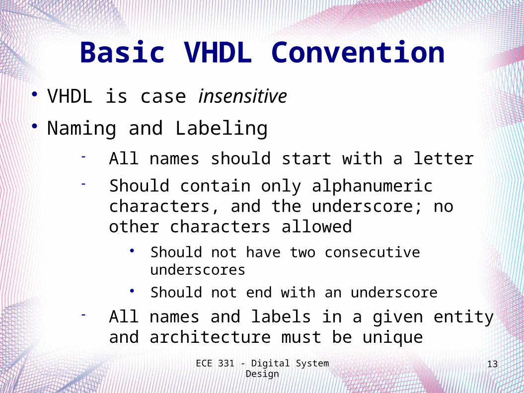
Basic VHDL Convention VHDL is case insensitive Naming and Labeling
All names should start with a letter Should contain only alphanumeric characters,
and the underscore; no other characters allowed
Should not have two consecutive underscores Should not end with an underscore
All names and labels in a given entity and architecture must be unique
ECE 331 - Digital System Design 14
Basic VHDL Convention
Free format language i.e. allows spacing for readability
Comments start with “--” and end at end of line Use one file per entity File names and entity names should match
ECE 331 - Digital System Design 15
Logic Circuits in VHDL
VHDL description includes two parts Entity statement Architecture statement
Entity Describes the interface (i.e. inputs and outputs)
Architecture Describes the circuit implementation

ECE 331 - Digital System Design 16
The Entity Statement
Keyword: Entity Requires a name Specifies the input and output ports
Ports have Name Mode Data type

ECE 331 - Digital System Design 17
Ports: Mode
IN Driver outside
entity Can be read
OUT Driver inside
entity Cannot be read
INOUT Driver inside and
outside entity Can be read
BUFFER Driver inside
entity Can be read
ECE 331 - Digital System Design 18
The Architecture Statement Keyword: Architecture Requires a name
The model is typically chosen as the name References the name in the associated Entity Specifies the functionality of the Entity
Using one of several types of implementations Architecture is associated with an entity
There can be multiple architectures for one entity, but only one can associated at a time.

ECE 331 - Digital System Design 19
The Architecture Statement VHDL Architecture Models
Functional Logic Functions Behavioral Includes Timing Information Structural Includes Components and
“Wires” Physical Specifies Package Information
Each model can be used to describe the functionality of a logic circuit.
Models are not mutually exclusive.
ECE 331 - Digital System Design 20
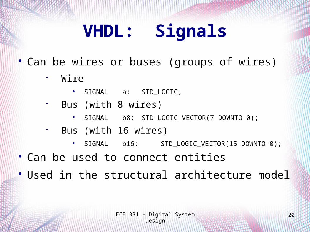
VHDL: Signals
Can be wires or buses (groups of wires) Wire
SIGNAL a: STD_LOGIC;
Bus (with 8 wires) SIGNAL b8: STD_LOGIC_VECTOR(7 DOWNTO 0);
Bus (with 16 wires) SIGNAL b16: STD_LOGIC_VECTOR(15 DOWNTO
0);
Can be used to connect entities Used in the structural architecture model
ECE 331 - Digital System Design 21
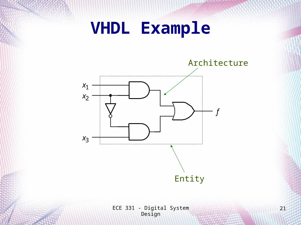
f
x3
x1x2
VHDL Example
Entity
Architecture
ECE 331 - Digital System Design 22
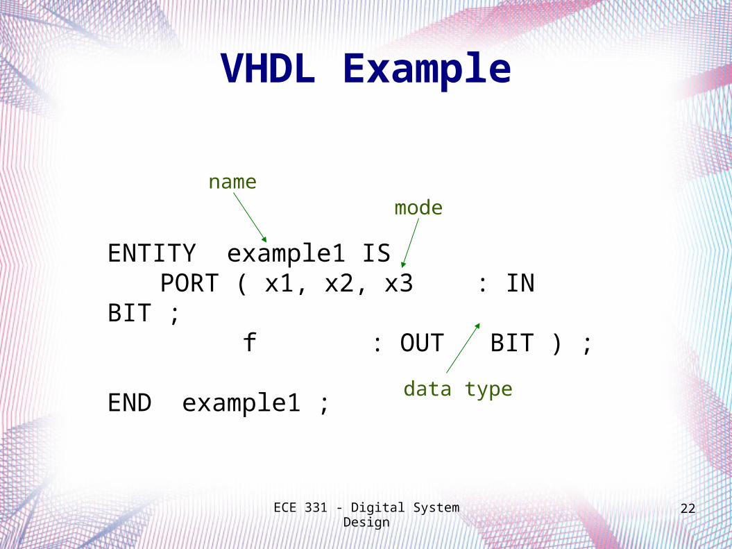
ENTITY example1 IS PORT ( x1, x2, x3 : IN BIT ;
f : OUT BIT ) ; END example1 ;
mode
data type
VHDL Example
name
ECE 331 - Digital System Design 23
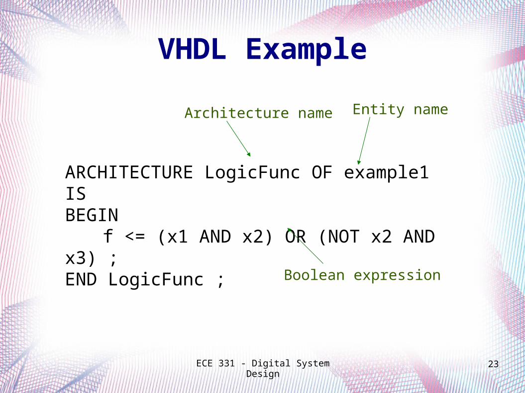
ARCHITECTURE LogicFunc OF example1 IS
BEGIN f <= (x1 AND x2) OR (NOT x2 AND
x3) ; END LogicFunc ;
Architecture name Entity name
Boolean expression
VHDL Example
Related Documents