Folder Number______ Name__________________________ a5 ECE 2210 / 00 homework # 1 Due: Mon, 8/26/19 There are a number of lockers on the 2nd floor of the MEB, in the center hallway. These lockers have slots cut in their doors so that homework and lab notebooks can be dropped through the slots. Turn in your homework in the locker marked "ECE 2210/00 Homework". (Sometimes lockers are separated as "ECE 2200 Homework" and "ECE 2210 Homework", look carefully the first time.) Homework is due by 5:00 p.m. on the due date The following problems are not meant to be hard. You should be able to do most of them in your head with no special formulas or calculations. In fact you should find them rather dumb and trivial. That's the point, I want to drill these concepts into your head so that you'll find them easy. 1. The figure at right shows a hydraulic system with a pump that converts rotational energy to fluid energy and two turbines which convert that energy back to rotational energy. Do NOT assume that the turbines are equal in size. This is a closed system containing an incompressible fluid with no places for that fluid to collect; i.e. flow in = flow out of any point or object. Kirchhoff's current law applies. The volumetric fluid flows are indicated by the arrows. I 1 . 0.01 m 3 s I 2 . 0.007 m 3 s I 3 = _________ I 4 = _________ I 5 = _________ I 6 = _________ 2. The figure at right shows an electrical circuit with a battery that converts chemical energy to electrical energy and two resistors which convert that electrical energy to heat energy. Do NOT assume that the resistors are equal in size. All electrical circuits are closed systems containing incompressible charges with no places for those charges to collect; i.e. flow in = flow out of any point or object. Kirchhoff's current law applies. . The electrical currents are indicated by the arrows. I 1 . 0.01 A I 2 . 0.007 A I 3 = _________ I 4 = _________ I 5 = _________ I 6 = _________ 3. The figure at right shows a similar electrical circuit only now the electrical currents are indicated by the arrows next to the wires. This is a more common way to show the current flow because a little arrow in the wire is too easily confused with the electrical symbol for a diode. You'll learn about diodes later. I 2 . 20 mA I 5 . 14 mA I 6 = _________ I 1 = _________ I 3 = _________ I 4 = _________ 4. I 3 . 0.004 m 3 s I 5 . 0.001 m 3 s I 4 = _________ I 2 = _________ I 1 = _________ I 6 = _________ I 7 = _________ I 8 = _________ ECE 2210 / 00 homework # 1, p.1

Welcome message from author
This document is posted to help you gain knowledge. Please leave a comment to let me know what you think about it! Share it to your friends and learn new things together.
Transcript
Folder Number______ Name__________________________a5
ECE 2210 / 00 homework # 1 Due: Mon, 8/26/19There are a number of lockers on the 2nd floor of the MEB, in the center hallway. These lockers have slots cut in their doors so that homework and lab notebooks can be dropped through the slots. Turn in your homework in the locker marked "ECE 2210/00 Homework". (Sometimes lockers are separated as "ECE 2200 Homework" and "ECE 2210 Homework", look carefully the first time.) Homework is due by 5:00 p.m. on the due date
The following problems are not meant to be hard. You should be able to do most of them in your head with no special formulas or calculations. In fact you should find them rather dumb and trivial. That's the point, I want to drill these concepts into your head so that you'll find them easy.
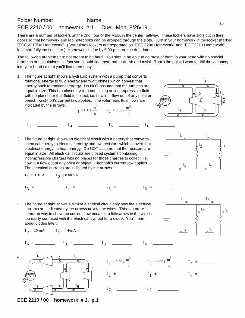
1. The figure at right shows a hydraulic system with a pump that converts rotational energy to fluid energy and two turbines which convert that energy back to rotational energy. Do NOT assume that the turbines are equal in size. This is a closed system containing an incompressible fluid with no places for that fluid to collect; i.e. flow in = flow out of any point or object. Kirchhoff's current law applies. The volumetric fluid flows are indicated by the arrows.
I 1.0.01m3
sI 2
.0.007m3
s
I 3 = _________ I 4 = _________ I 5 = _________ I 6 = _________
2. The figure at right shows an electrical circuit with a battery that converts chemical energy to electrical energy and two resistors which convert that electrical energy to heat energy. Do NOT assume that the resistors are equal in size. All electrical circuits are closed systems containing incompressible charges with no places for those charges to collect; i.e. flow in = flow out of any point or object. Kirchhoff's current law applies. . The electrical currents are indicated by the arrows.
I 1.0.01 A I 2
.0.007 A
I 3 = _________ I 4 = _________ I 5 = _________ I 6 = _________
3. The figure at right shows a similar electrical circuit only now the electrical currents are indicated by the arrows next to the wires. This is a more common way to show the current flow because a little arrow in the wire is too easily confused with the electrical symbol for a diode. You'll learn about diodes later.
I 2.20 mA I 5
.14 mA
I 6 = _________ I 1 = _________ I 3 = _________ I 4 = _________
4.I 3
.0.004m3
sI 5
.0.001m3
sI 4 = _________
I 2 = _________ I 1 = _________ I 6 = _________
I 7 = _________ I 8 = _________
ECE 2210 / 00 homework # 1, p.1
ECE 2210 / 00 homework # 1, p.2
5.I 3
.4.5 mA I 5.1.2 mA I 4 = _________
I 2 = _________ I 1 = _________ I 6 = _________
I 7 = _________ I 8 = _________
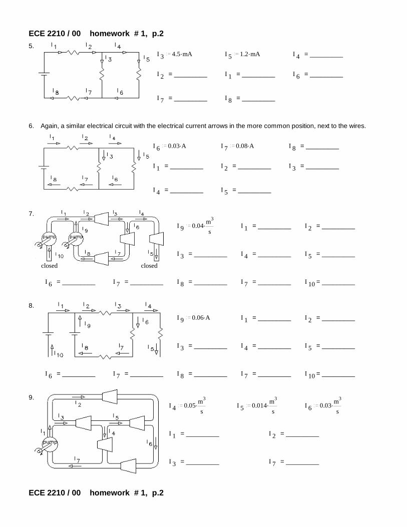
6. Again, a similar electrical circuit with the electrical current arrows in the more common position, next to the wires.
I 6.0.03 A I 7
.0.08 A I 8 = _________
I 1 = _________ I 2 = _________ I 3 = _________
I 4 = _________ I 5 = _________
7.
I 9.0.04m3
sI 1 = _________ I 2 = _________
I 3 = _________ I 4 = _________ I 5 = _________
closed closed
I 6 = _________ I 7 = _________ I 8 = _________ I 7 = _________ I 10 = _________
8.
I 9.0.06 A I 1 = _________ I 2 = _________
I 3 = _________ I 4 = _________ I 5 = _________
I 6 = _________ I 7 = _________ I 8 = _________ I 7 = _________ I 10 = _________
9.I 4
.0.05m3
sI 5
.0.014m3
sI 6
.0.03m3
s
I 1 = _________ I 2 = _________
I 3 = _________ I 7 = _________
ECE 2210 / 00 homework # 1, p.2

ECE 2210 / 00 homework # 1, p.3
10. I 4.20 mA I 5
.10 mA I 6.22 mA
I 1 = _________ I 2 = _________
I 3 = _________ I 7 = _________
11. Careful here, there are now two pumps. Also, given the flow arrows shown, one or more of the flows must comeout negative.
I 2.0.005m3
sI 6
.0.03m3
sI 7
.0.015m3
s
I 1 = _________ I 3 = _________
I 4 = _________ I 5 = _________
12. What does a negative fluid flow physically mean?
13. I 1.0.01 A I 5
.20 mA I 6.35 mA
I 2 = _________ I 3 = _________
I 4 = _________ I 7 = _________
14. What does a negative electrical current physically mean?
15.I 4
.0.05m3
sI 5
.0.03m3
sI 7
.0.045m3
s
I 9.0.06m3
sI 1 = _________
I 2 = _________ I 3 = _________
I 6 = _________ I 8 = _________
I 10 = _________ I 11 = _________
ECE 2210 / 00 homework # 1, p.3
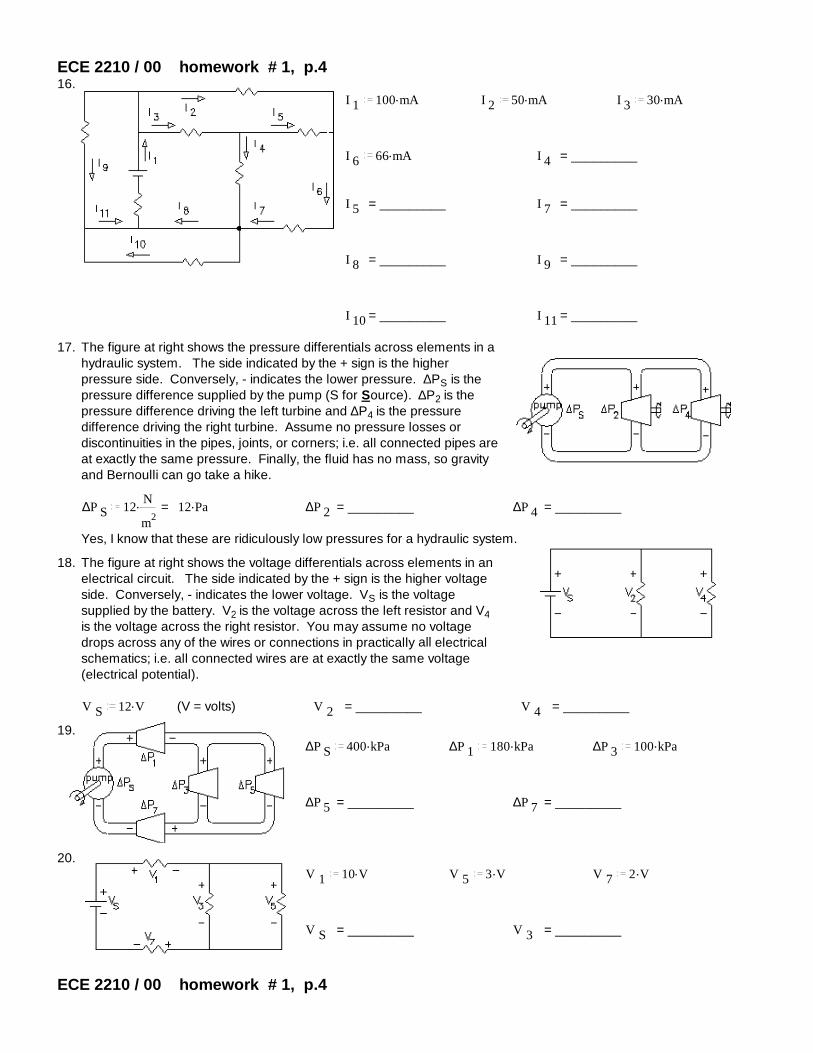
ECE 2210 / 00 homework # 1, p.416.
I 1.100 mA I 2
.50 mA I 3.30 mA
I 6.66 mA I 4 = _________
I 5 = _________ I 7 = _________
I 8 = _________ I 9 = _________
I 10 = _________ I 11 = _________
17. The figure at right shows the pressure differentials across elements in a hydraulic system. The side indicated by the + sign is the higher pressure side. Conversely, - indicates the lower pressure. ∆PS is the pressure difference supplied by the pump (S for Source). ∆P2 is the pressure difference driving the left turbine and ∆P4 is the pressure difference driving the right turbine. Assume no pressure losses or discontinuities in the pipes, joints, or corners; i.e. all connected pipes are at exactly the same pressure. Finally, the fluid has no mass, so gravity and Bernoulli can go take a hike.
∆P S.12
N
m2= .12 Pa ∆P 2 = _________ ∆P 4 = _________
Yes, I know that these are ridiculously low pressures for a hydraulic system.
18. The figure at right shows the voltage differentials across elements in an electrical circuit. The side indicated by the + sign is the higher voltage side. Conversely, - indicates the lower voltage. VS is the voltage supplied by the battery. V2 is the voltage across the left resistor and V4 is the voltage across the right resistor. You may assume no voltage drops across any of the wires or connections in practically all electrical schematics; i.e. all connected wires are at exactly the same voltage (electrical potential).
V S.12 V (V = volts) V 2 = _________ V 4 = _________
19.∆P S
.400 kPa ∆P 1.180 kPa ∆P 3
.100 kPa
∆P 5 = _________ ∆P 7 = _________
20.V 1
.10 V V 5.3 V V 7
.2 V
V S = _________ V 3 = _________
ECE 2210 / 00 homework # 1, p.4
ECE 2210 / 00 homework # 1, p.5
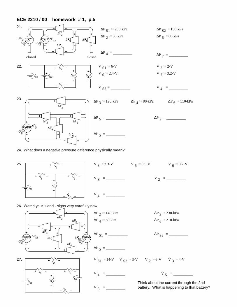
21. ∆P S1.200 kPa ∆P S2
.150 kPa
∆P 2.50 kPa ∆P 6
.60 kPa
∆P 4 = _________ ∆P 7 = _________closed closed
22. V S1.6 V V 2
.2 V
V 6.2.4 V V 7
.3.2 V
V S2 = _________ V 4 = _________
23. ∆P 3.120 kPa ∆P 4
.80 kPa ∆P 6.110 kPa
∆P S = _________ ∆P 2 = _________
∆P 5 = _________
24. What does a negative pressure difference physically mean?
25. V 3.2.3 V V 5
.0.5 V V 6.3.2 V
V S = _________ V 2 = _________
V 4 = _________
26. Watch your + and - signs very carefully now.
∆P 2.140 kPa ∆P 3
.230 kPa
∆P 4.50 kPa ∆P 6
.210 kPa
∆P S1 = _________ ∆P S2 = _________
∆P 5 = _________
27. V S1.14 V V S2
.3 V V 2.6 V V 3
.4 V
V 4 = _________ V 5 = _________
Think about the current through the 2nd battery. What is happening to that battery?V 6 = _________

ECE 2210 / 00 homework # 1, p.6
28. ∆P 1.200 kPa ∆P 2
.1100 kPa
∆P 3.600 kPa ∆P 9
.1800 kPa
∆P S = _________ ∆P 4 = _________
∆P 5 = _________ ∆P 6 = _________
∆P 10 = _________
29.V S
.18 V V 3.6 V V 4
.8 V V 5.2 V
V 1 = _________ V 2 = _________
V 6 = _________ V 9 = _________
V 10 = _________
Answers
1. I 3 = I 4 = I 5.0.003m3
s, I 6
.0.01m3
s2. I 3 = I 4 = I 5
.0.003 A , I 6.0.01 A
3. I 6 = I 1.34 mA , I 3 = I 4
.14 mA 4. I 4= I 6.0.001m3
s, I 1= I 2= I 7= I 8
.0.005m3
s5. I 4= I 6
.1.2 mA , I 1= I 2= I 7= I 8.5.7 mA 6. I 1= I 2= I 8
.80 mA , I 3.50 mA , I 4= I 5
.30 mA
8. I 1= I 10 = I 4= I 5.0 A ,
7. I 1= I 10 = I 4= I 5.0m3
s, I 2= I 3 = I 7= I 8
.0.04m3
s I 2= I 3 = I 7= I 8.0.06 A
9. I 1= I 7.0.080m3
s, I 2
.0.016m3
s, I 3
.0.064m3
s10. I 1= I 7
.42 mA , I 2.12 mA , I 3
.30 mA
12. Actual flow is in direction opposite to the arrow direction.
11. I 1.0.015m3
s, I 3
.0.010m3
s, I 4
.0.045m3
s, I 5
.0.035m3
s13. I 2
.15 mA, I 3.25 mA , I 4
.45 mA , I 7.10 mA 14. "
15. I 1.0.155m3
s, I 2
.0.015m3
s, I 3
.0.080m3
s, I 6
.0.045m3
s, I 8
.0.095m3
s, I 10
.0m3
s, I 11
.0.060m3
s16. I 4
.14 mA , I 5.16 mA , I 7
.66 mA , I 8.80 mA , I 9
.20 mA , I 10.0 mA , I 11
.20 mA
17. ∆P 2 = ∆P 4.12 Pa 18. V 2 = V 4
.12 V
19. ∆P 5.100 kPa , ∆P 7
.120 kPa 20. V S.15 V , V 3
.3 V
21. ∆P 4.0 kPa , ∆P 7
.40 kPa 22. V S2.7.6 V , V 4
.0 V
23. ∆P S.200 kPa , ∆P 2
.90 kPa , ∆P 5.30 kPa 24. The actual + & - should be reversed from those on drawing
25. V S.6 V , V 2
.2.8 V , V 4.3.7 V 26. ∆P S1
.280 kPa , ∆P S2.350 kPa , ∆P 5
.90 kPa
27. V 4.10 V, V 5
.2 V , V 6.5 V battery is charging 28. ∆P S
.2000 kPa , ∆P 4.1200 kPa , ∆P 5
.500 kPa ,∆P 6
.700 kPa , ∆P 10.0 kPa
29. V 1.4 V , V 2
.8 V , V 6.6 V , V 9
.14 V, V 10.0 V
ECE 2210 / 00 homework # 1, p.6

Folder Number______ Name__________________________ a5
ECE 2210 / 00 homework # 2 Due: Thurs, 8/29/19Don't forget: Write your folder number in the upper-left corner of ALL your homework.
Graded homework, labs and exams will be returned to a file cabinet in MEB 2101, filed by your alphabetically-assigned folder number.
You may do the following problems here or on your own paper. But, since you have the answers, you MUST show your work to get credit .
I1. Ohm's law
Consider the figure at right For each of the cases below, find the missing value.
V S V R R
a) I .0.01 A V R.4 V R = ?
b) I .50 mA R .560 Ω V R= ?
c) V R.12 V R .1.5 kΩ I = ?
2. Power and Ohm's law. Same circuit as above. For each of the cases below, find the missing values.
a) I .5 mA R .2 kΩ V R= P R =
b) V R.25 V R .100 Ω I = P R =
c) V R.20 V I .0.01 A R = P R =
Ignore the fact that the following items run on AC
d) P R.900 W V R
.120 V I = R =Toaster
e) P R.1500 W R .9.6 Ω I = V S =
Hair drier
f) P R.2500 W I .10.5 A R = V S =
Electric oven
3. Find the equivalent resistance of each of these networks, i.e. what would an ohmmeter read if hooked to the terminals.
a)R 2
.1.0 kΩ R 4.5.6 kΩ
R 1.1.8 kΩ R 3
.2.5 kΩ
ECE 2210 / 00 homework # 2 p.1
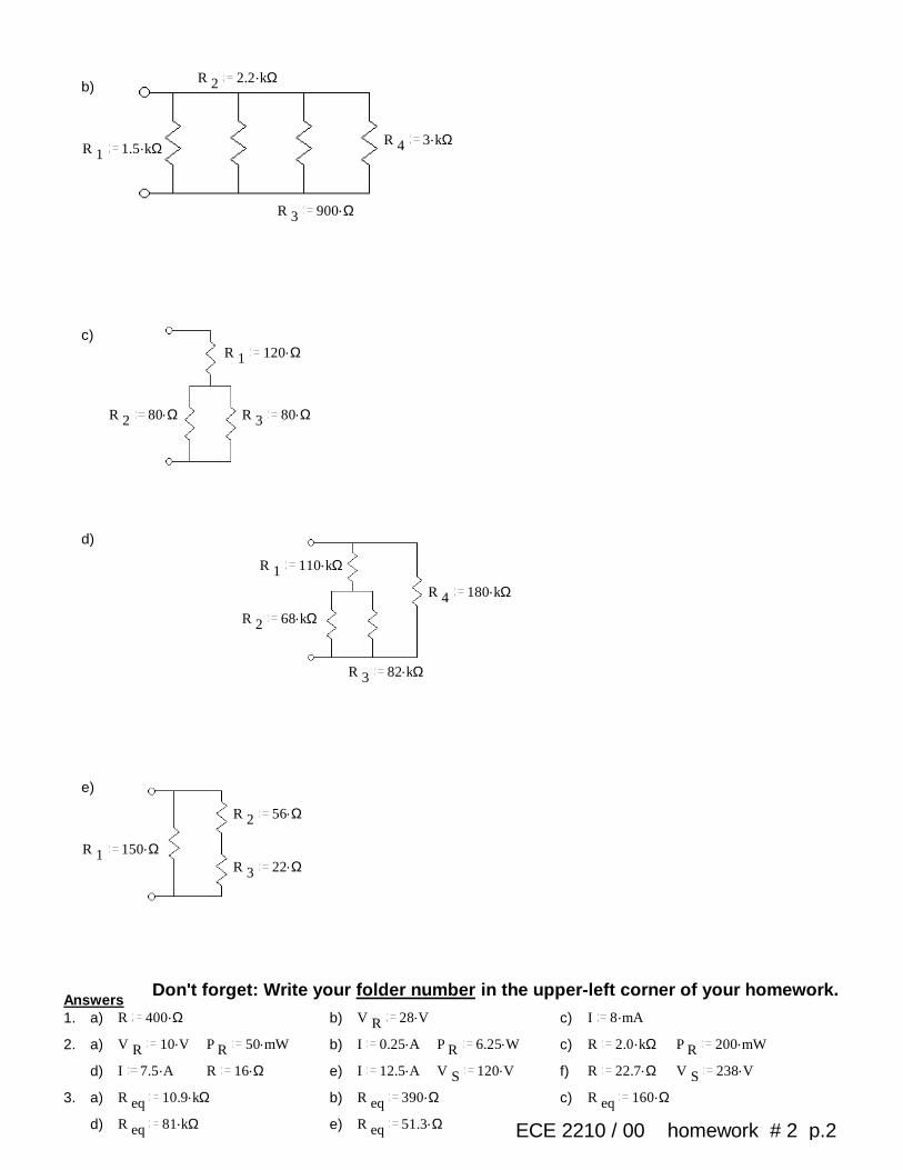
R 2.2.2 kΩ
b)
R 4.3 kΩ
R 1.1.5 kΩ
R 3.900 Ω
c)R 1
.120 Ω
R 2.80 Ω R 3
.80 Ω
d)
R 1.110 kΩ
R 4.180 kΩ
R 2.68 kΩ
R 3.82 kΩ
e)
R 2.56 Ω
R 1.150 Ω
R 3.22 Ω
Don't forget: Write your folder number in the upper-left corner of your homework.Answers1. a) R .400 Ω b) V R
.28 V c) I .8 mA
2. a) V R.10 V P R
.50 mW b) I .0.25 A P R.6.25 W c) R .2.0 kΩ P R
.200 mW
d) I .7.5 A R .16 Ω e) I .12.5 A V S.120 V f) R .22.7 Ω V S
.238 V
3. a) R eq.10.9 kΩ b) R eq
.390 Ω c) R eq.160 Ω
d) R eq.81 kΩ e) R eq
.51.3 Ω ECE 2210 / 00 homework # 2 p.2

ECE 2210 / 00 homework # 3 Due: Wed, 9/4/19 You should finish p.1 by Mon.Graded homework, labs and exams will be returned to a file cabinet in MEB 2101, filed by your alphabetically-assigned folder number.Answer the following problems on your own paper. Since you have the answers, you must show the equations and work you used to arrive at the answer to get credit.
Don't forget: Write your folder number in the upper-left corner of your homework.
Equivalent resistance1. Find the equivalent resistance of each of these networks, i.e. what would an ohmmeter read if hooked to the
terminals. Work out and keep all your intermediate results -- they will help you in the problems to come.
a) b) R 1.27 Ω
R 1.56 kΩ R 3
.97 kΩR 3R 2
.100 Ω R 4.56 Ω
.20 Ω
R 2.110 kΩ R 4
.82 kΩR 6
.39 ΩR 5
.75 ΩR 7
.51 Ω
Note: the hard part of these problems is actually seeing which resistors are in parallel and which are in series. You may want to redraw the circuits a few times to help you figure it out.
Voltage dividersR 1
.1.5 kΩ2. a) Use the voltage divider concept to find the voltage across each of the
resistors in the circuit at right. V R1 = ? V R2 = ? V R3 = ?V S
.6 Vb) Confirm that the three resistor voltages add up to the source
voltage, ie, confirm Kirchoff's voltage law.R 2
.1.0 kΩ
c) Without recalculating anything, what would happen to all the resistor voltages if the source voltage were doubled? Tripled?
R 3.2.2 kΩ
3. The circuit at right is known as a wheatstone bridge, or simply a bridge. It is a very common measurement circuit, used with strain gauges, thermisters, and other devices whose resistance changes in response to something that you'd like to measure. Let's assume the resistors in this circuit are 100Ω strain gauges. The resistance of these gauges changes slightly when you stretch or compress them. They are glued to a material (often steel) and are used to measure deformations of the material (called strain).a) Due to deformation, R1 and R4 decrease by 1% and R2 and R3 increase by 1%. Find Vab.
b) Due to a temperature change, the resistances of all the gages increase by 5%. Find the % change in Vab.
c) Why do you think the bridge circuit is used in this case?
4. Use voltage divider concepts to find the voltages indicated in the following circuits. You may want to use some of your results from problem 1. You may need to use the voltage divider equation more than once.
a) b) R 8.12 Ω R 1
.27 Ω R 3.20 Ω
R 1.56 kΩ R 3
.97 kΩR 4
.56 ΩR 2
.100 ΩV S
.36 V
R 4.82 kΩ
R 2.110 kΩ V S
.10 VR 6
.39 ΩR 5
.75 Ω
R 5.15 kΩ
R 7.51 Ω
V R5 = ? V R4 = ? V R1 = ?
V R8 = ? V R2 = ? V R1 = ?ECE 2210 / 00 homework # 3 p.1

ECE 2210 / 00 homework # 3 p.2Current Dividers5. The circuit at right shows a current source hooked to a resistor
network. Remember that the grounds are all connected together. You can draw lines between them if it helps you.
R 1.1.1 kΩ
I S.35 mA R 4
.1.5 kΩa) Use the current divider concept to find the current
through each of the resistors in the circuit at right.R 2
.0.68 kΩI R1 = ? I R2 = ? I R3 = ? I R4 = ?
b) Confirm that IR2 + IR3 = IR1 and that IR1 + IR4 = IS, ie, confirm Kirchoff's current law twice. R 3
.0.82 kΩ
c) Without recalculating anything, what would happen to all the currents if the source current were doubled? Tripled?
6. Refer back to the circuit of problem 4b. a) Find the equivalent resistance as seen by the source (R8 + your answer for problem 1b) and use that to find the
source current (IS or IR8).
b) Find these currents by current divider methods. I R2 = ? I R1 = ? I R4 = ?
c) Using Ohm's law and the currents you found in this problem, confirm the voltages found in problem 4b.
Power7. Refer to the circuit of problem 2.
a) How much power is dissipated by each resistor? P R1 = ? P R2 = ? P R3 = ?
b) Independently determine the power that the source is contributing to the circuit. P S = .V S I S = ?
c) Show that power is conserved (Σ answers to a = answer to b).
8. Refer to the circuit of problem 5.
a) How much power is dissipated by each resistor? P R1 = ? P R2 = ? P R3 = ? P R4 = ?
b) Independently determine the power that the source is contributing to the circuit. P S = .V S I S = ?
c) Show that power is conserved.I D
.0.2 A9. The circuit at right has five unknown components labeled A through E.
a) Which of the components are absorbing power from the circuit?V B
.2 Vb) Which of the components are contributing power to the circuit?
V D.8 V
c) Show that power is conserved.V E
.4 V
AnswersI C
.0.3 A1. a) R eq
.82.5 kΩ b) R eq.41.7 Ω
2. a) .1.91 V , .1.28 V , .2.81 V b) =.1.91 V .1.28 V .2.81 V 6 V c) double, triple
3. a) .100 mV b) 0% change c) Reading won't be affected by temperature.
4. a) .5.54 V , .17.35 V , .13.11 V b) .2.23 V , .7.77 V , .2.93 V
5. a) .17.67 mA , 9.66mA , .8.01 mA, .17.33 mA b) both check c) double, triple
6. a) .53.7 Ω , .0.186 A b) .77.65 mA , .108.6 mA , .28.6 mA c) all agree
7. a) .2.44 mW, .1.63 mW, .3.59 mW b) .7.66 mW c) P S = P R1 P R2 P R3
8. a) .0.343 W, .0.0634 W , .0.0526 W , .0.451 W b) .0.910 W c) P R1 P R2 P R3 P R4 = P S
9. a) C, D, E b) A, B c) .6 W = .6 WDon't forget: Write your folder number in the upper-left corner of your homework.ECE 2210 / 00 homework # 3 p.2

aECE 2210 / 00 homework # 4 Due: Fri, 9/6/19Answer the following problems on your own paper. Show your equations and work to get credit on this and all future homeworks.
Don't forget: Write your folder number in the upper-left corner of your homework.
SuperpositionR 1
.1 kΩ R 2.500 Ω
1. Use superposition to find I3. Circle your intermediate solutions on your paper. Your intermediate solutions show how much of I3 is due to VS1, and how much is due to VS2.
V S1.8 V
R 3.1 kΩ
V S2.10 V
2. Use superposition to solve following problems: Each problem asks for both a current and a voltage.
Clearly indicate your intermediate answers, the grader will look for those.
a) The letter "a" is the name of the "node" at the black dot. Va is a node voltage, referenced to ground.R 1
.40 Ω V a = ? V a = V R3
I R1= ? R 2.120 Ω
R 3.120 Ω
V S1.5 V
V S2.6 V
These are ground symbols. They are all connected together, although that connection is not explicitly shown.
b)
I R2= ?R 2
.22 Ω I S.0.5 A
R 1.11 Ω
V R1 = ?
V S.12 V
c) Watch your signs. R 2.3 kΩ R 3
.1 kΩa
V a = ?
I R1= ? R 4.2 kΩ
R 1.3 kΩ
V S.4.5 V
I S.3 mA
Answers
1. =.2 mA .5 mA 7 mA
2. a) .4.2 V , .20 mA b) .7.67 V , .197 mA Don't forget: Write your folder number in the upper-left corner of your homework.c) .0.5 V , .0.5 mA
ECE 2210 / 00 homework # 4 HW 5 on Back ----------->
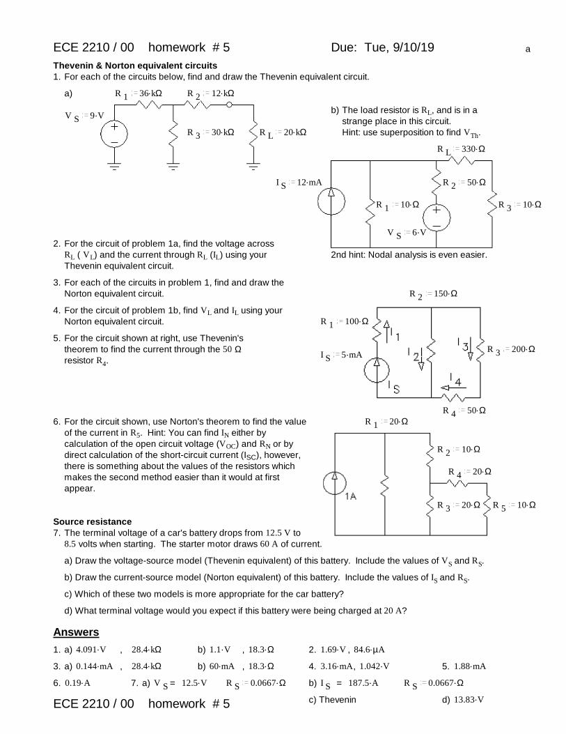
ECE 2210 / 00 homework # 5 Due: Tue, 9/10/19 a
Thevenin & Norton equivalent circuits1. For each of the circuits below, find and draw the Thevenin equivalent circuit.
a) R 1.36 kΩ R 2
.12 kΩ
b) The load resistor is RL, and is in a strange place in this circuit. Hint: use superposition to find VTh.
V S.9 V
R 3.30 kΩ R L
.20 kΩ
R L.330 Ω
I S.12 mA R 2
.50 Ω
R 1.10 Ω R 3
.10 Ω
V S.6 V
2. For the circuit of problem 1a, find the voltage across RL ( VL) and the current through RL (IL) using your Thevenin equivalent circuit.
2nd hint: Nodal analysis is even easier.
3. For each of the circuits in problem 1, find and draw the Norton equivalent circuit. R 2
.150 Ω
4. For the circuit of problem 1b, find VL and IL using your Norton equivalent circuit. R 1
.100 Ω
5. For the circuit shown at right, use Thevenin's theorem to find the current through the 50 Ω resistor R4.
R 3.200 Ω
I S.5 mA
R 4.50 Ω
6. For the circuit shown, use Norton's theorem to find the value of the current in R5. Hint: You can find IN either by calculation of the open circuit voltage (VOC) and RN or by direct calculation of the short-circuit current (ISC), however, there is something about the values of the resistors which makes the second method easier than it would at first appear.
R 1.20 Ω
R 2.10 Ω
R 4.20 Ω
R 3.20 Ω R 5
.10 Ω
Source resistance7. The terminal voltage of a car's battery drops from 12.5 V to
8.5 volts when starting. The starter motor draws 60 A of current.
a) Draw the voltage-source model (Thevenin equivalent) of this battery. Include the values of VS and RS.
b) Draw the current-source model (Norton equivalent) of this battery. Include the values of IS and RS.
c) Which of these two models is more appropriate for the car battery?
d) What terminal voltage would you expect if this battery were being charged at 20 A?
Answers
1. a) .4.091 V , .28.4 kΩ b) .1.1 V , .18.3 Ω 2. .1.69 V , .84.6 µA
3. a) .0.144 mA , .28.4 kΩ b) .60 mA , .18.3 Ω 4. .3.16 mA, .1.042 V 5. .1.88 mA
6. .0.19 A 7. a) V S = .12.5 V R S.0.0667 Ω b) I S = .187.5 A R S
.0.0667 Ω
c) Thevenin d) .13.83 VECE 2210 / 00 homework # 5

ECE 2210 / 00 homework # 6 Due: Fri, 9/13/19 a
Nodal Analysis1. a) If you select the bottom node as ground, how many unknown node
voltages remain? (Assume VS is a known quantity.) How many simultaneous equations would you need to solve to analize this circuit?
b) Use nodal analysis to find all the necessary simultaneous equations.
R 5.2 Ω
2. a) Use nodal analysis to find all the node voltages.
b) Your node voltages will depend on your selection of a reference node (ground) as well as your arbitrary node labels, so the grader won't look at these specifically. Use your node voltages to find the potential (voltage) across each resistor. Report the magnitude and polarity of each.
V s.5 V
R 2.2 Ω
R 1.4 Ω R 3
.2 Ω R 4.2 Ω
R 1.1 kΩ R 2
.500 Ω3. Use Nodal analysis to find Va and use Va to find I3.
V A.8 V
R 3.1 kΩ
V B.10 V
4. Use Nodal analysis to solve following problems: Each problem asks for at least 1 voltage and a current. Use the voltage(s) to find the current.
a)R 1
.40 Ω V a = ? b) R 3.1 kΩ
V a = ? V b = ?
R 2.120 Ω
I R1= ? I R1= ? R 4.2 kΩ
R 3.120 Ω
R 2.3 kΩ
V S.4.5 V
V S1.5 V
V S2.6 V I S
.3 mAR 1
.3 kΩ
Don't forget your folder number . hint: you may be able to eliminate one unknown node for the initial calculation.
Answers1. a) 3,3 b) .V a
1
R 1
1
R 2
1
R 3
V b
R 2
V c
R 3=
V S
R 1,
V a
R 2
.V b1
R 2
1
R 5
1
R 4
V c
R 4= .0 A
V a
R 3
V b
R 4
.V c1
R 3
1
R 4
1
R 6= .0 A
2. a) Answer will depend on your choice of ground, so check your answers to part b to see if you did part a right.b) .3.077 V , + bottom , .2.308 V , + left , .1.923 V , + top , .0.385 V , + bottom , .2.692 V , + right
3. .7 V , .7 mA 4. a) .4.2 V , .20 mA b) V a.1.5 V V b
.0.5 V I R1.0.5 mA
You may not get this homework back before the 1st exam. Photocopy it if you want to be sure to have it.
ECE 2210 / 00 homework # 6

ECE 2210 / 00 homework # 7 Due: Tue, 9/17/19 a
1st exam on Thur. 9/19 will include this materialAnswer the following problems on your own paper.
1. For each of the following sinusoidal waves, find: a)
1) peak-to-peak voltage or current, Vpp or Ipp2) amplitude, A, Vp, or Ip3) period, T4) frequency f in cycles/sec or Hz5) an expression for v(t) or i(t) in terms of Acos(ωt + φ) the frequency ω is in radians/sec the phase angle φ is in rad/sec or degrees
b)
c)
2. For each of the following waveforms, find: 2a)1) Peak-to-peak voltage or current, Vpp or Ipp2) Average, (VDC, IDC, Vave, or Iave)3) Period, T4) Frequency f in cycles/sec or Hz
b)
c)
3. For problem 2a above, write a full expression for v(t) in terms of v(t) = Acos(ωt + φ) + VDC
Answers1. a) .0.2 V .0.1 V .12 ms .83.3 Hz ..0.1 V cos( ).523.6 t 2. a) .12 V .3 V .6 ms .167 Hz
b) .24 V .12 V .0.018 ms .55.6 kHz b) .12 V .6 V .4 ms .250 Hzv( )t ..12 V cos( ).349100 t .90 deg
c) .250 mA .25 mA .0.6 ms .1.667 kHzc) .16 mA .8 mA .0.3 ms .3333 Hz
..8 mA cos( ).20940 t .150 deg 3. v( )t ..6 V cos( ).1047 t .90 deg .3 V
ECE 2210 / 00 homework # 7

ECE 2210 / 00 homework # 8 Due: Fri, 9/20/19 a2
1st exam on Thur. 9/19 may include p.1 of this homework (Listen for details in class)
1) Find Ceq in each case
a) b)C 1
.0.02 µFC 1
.0.2 µF C 2.0.4 µF
C 2.0.06 µF
c)
C 2.3 µF
C 1.3 µF
C 3.1.2 µF C 4
.1.8 µF
2. Each of the following circuits have been connected as shown for a long time.Find the voltage across each capacitor and the energy stored in each.
R 1.220 Ω
a)
C .5 µFV S
.5.5 V
R 2.330 Ω
b) R 1.2.4 kΩ
C .0.47 µFR 2
.1.5 kΩ
I S.25 mA
c) R 2.4.8 kΩ C 1
.0.68 µF
R 3.10 kΩ
R 1.22 kΩ
C 2.0.22 µF
V S.16 V
ECE 2210 / 00 homework # 8
Folder ________ ECE 2210 / 00 homework # 8
Name: __________________________________You may want to hand in this page with answers to problems 3 & 4.
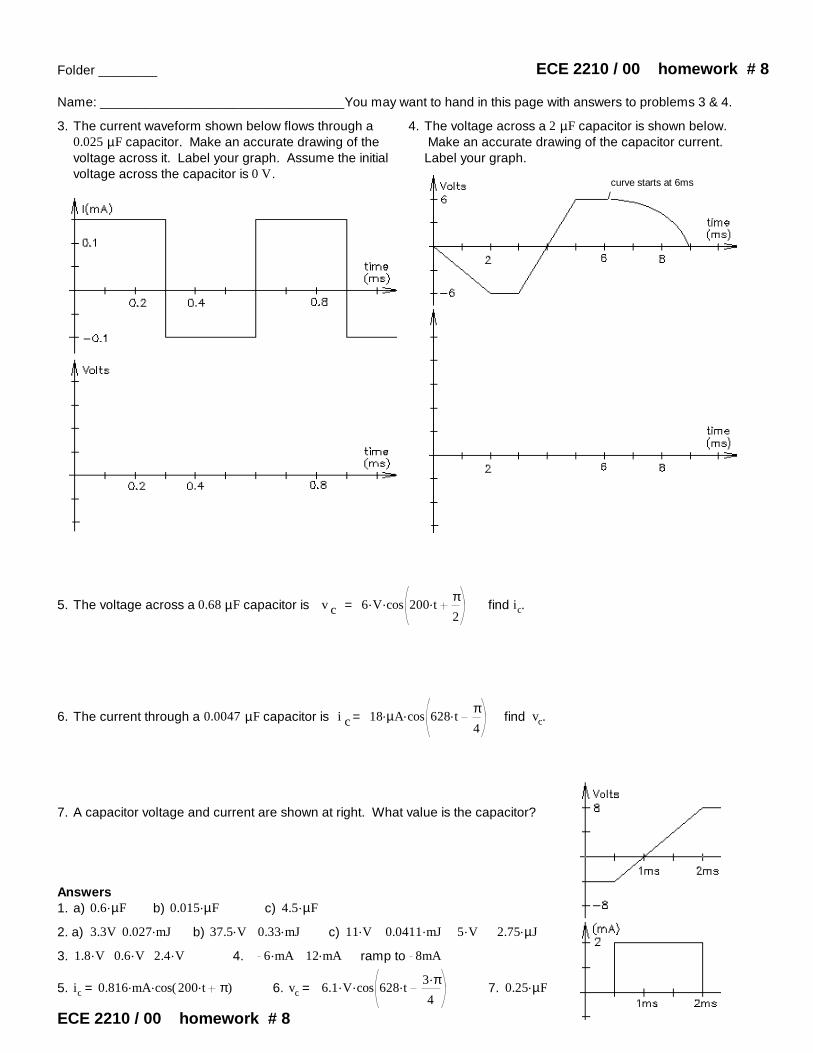
3. The current waveform shown below flows through a 0.025 µF capacitor. Make an accurate drawing of the voltage across it. Label your graph. Assume the initial voltage across the capacitor is 0 V.
4. The voltage across a 2 µF capacitor is shown below. Make an accurate drawing of the capacitor current. Label your graph.
curve starts at 6ms/
5. The voltage across a 0.68 µF capacitor is v c = ..6 V cos .200 tπ2
find ic.
6. The current through a 0.0047 µF capacitor is i c = ..18 µA cos .628 tπ4
find vc.
7. A capacitor voltage and current are shown at right. What value is the capacitor?
Answers1. a) .0.6 µF b) .0.015 µF c) .4.5 µF
2. a) 3.3V .0.027 mJ b) .37.5 V .0.33 mJ c) .11 V .0.0411 mJ .5 V .2.75 µJ
3. .1.8 V .0.6 V .2.4 V 4. .6 mA .12 mA ramp to 8mA
5. ic = ..0.816 mA cos( ).200 t π 6. vc = ..6.1 V cos .628 t.3 π4
7. .0.25 µF
ECE 2210 / 00 homework # 8

Folder ________ Name: ________________________________
ECE 2210 / 00 hw # 9 Due: Thur, 9/26/19You will need another paper for your calculations, but you may want to hand this sheet in with your drawings.
1. Find Leq in each caseb)
a) L 1.0.22 mH
L 1.2 mH L 2
.3 mH
L 2.0.4 mH
2. Find the stored energy in each capacitor and/or inductor under steady-state conditions. Note: Treat caps as opens and inductors as shorts to find DC voltages and currents. C 2
.2 µF
a) b)L 1
.0.5 mH R 1.30 Ω
R .200 ΩL .40 mH.10 V
L 2.4 mH
V S.18 V
R 3.30 Ω
C 1.10 µF
R 2.60 Ω
3. The current waveform shown below flows through a 2 mH inductor. Make an accurate drawing of the voltage across it. Label your graph.
4. The voltage across a 0.5 mH inductor is shown below. Make an accurate drawing of the inductor current. Label your graph. Assume the initial current is 0 mA.
The curve is 2nd order and starts at 6ms
0 0.1 0.2 0.3 0.4 0.5 0.6 0.7 0.8 0.9 1 1.1
2
1
1
2
3
4
0 1 2 3 4 5 6 7 8 9 10
8
6
4
2
2
4
6
8
v Li L / (volts)
(mA)
time (ms)
time (ms)
0 1 2 3 4 5 6 7 8 9 10 0 0.1 0.2 0.3 0.4 0.5 0.6 0.7 0.8 0.9 1 1.1
v L i L
time (ms) time (ms)
ECE 2210 / 00 homework # 9
ECE 2210 / 00 homework # 9
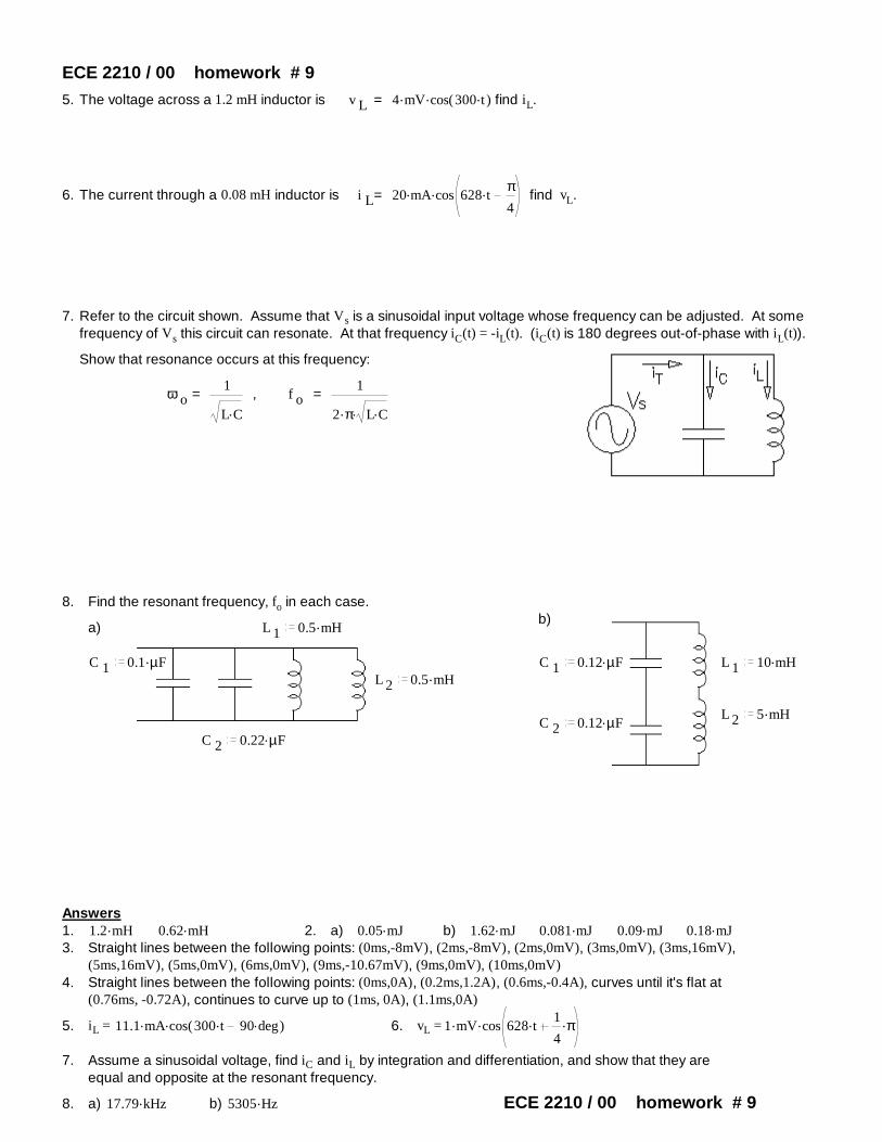
5. The voltage across a 1.2 mH inductor is v L = ..4 mV cos( ).300 t find iL.
6. The current through a 0.08 mH inductor is i L= ..20 mA cos .628 tπ4
find vL.
7. Refer to the circuit shown. Assume that Vs is a sinusoidal input voltage whose frequency can be adjusted. At some frequency of Vs this circuit can resonate. At that frequency iC(t) = -iL(t). (iC(t) is 180 degrees out-of-phase with iL(t)).
Show that resonance occurs at this frequency:
ω o =1
.L C
, f o =1
..2 π .L C
8. Find the resonant frequency, fo in each case.b)
a) L 1.0.5 mH
C 1.0.1 µF C 1
.0.12 µF L 1.10 mH
L 2.0.5 mH
L 2.5 mH
C 2.0.12 µF
C 2.0.22 µF
Answers1. .1.2 mH .0.62 mH 2. a) .0.05 mJ b) .1.62 mJ .0.081 mJ .0.09 mJ .0.18 mJ3. Straight lines between the following points: (0ms,-8mV), (2ms,-8mV), (2ms,0mV), (3ms,0mV), (3ms,16mV),
(5ms,16mV), (5ms,0mV), (6ms,0mV), (9ms,-10.67mV), (9ms,0mV), (10ms,0mV) 4. Straight lines between the following points: (0ms,0A), (0.2ms,1.2A), (0.6ms,-0.4A), curves until it's flat at
(0.76ms, -0.72A), continues to curve up to (1ms, 0A), (1.1ms,0A)
5. iL = ..11.1 mA cos( ).300 t .90 deg 6. vL = ..1 mV cos .628 t .1
4π
7. Assume a sinusoidal voltage, find iC and iL by integration and differentiation, and show that they are equal and opposite at the resonant frequency.
8. a) .17.79 kHz b) .5305 Hz ECE 2210 / 00 homework # 9
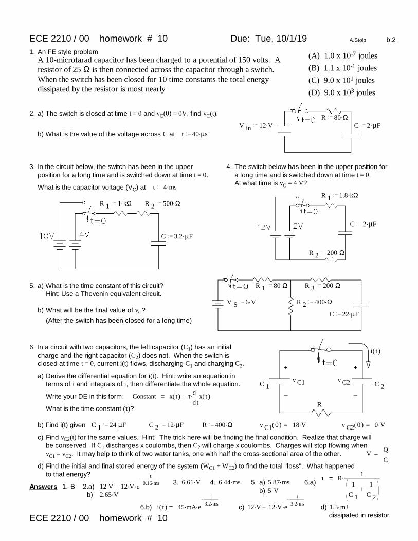
ECE 2210 / 00 homework # 10 Due: Tue, 10/1/19 A.Stolp b.2
1. An FE style problem (A) 1.0 x 10⁻⁷ joulesA 10-microfarad capacitor has been charged to a potential of 150 volts. A resistor of 25 Ω is then connected across the capacitor through a switch. When the switch has been closed for 10 time constants the total energy dissipated by the resistor is most nearly
(B) 1.1 x 10⁻¹ joules
(C) 9.0 x 101 joules
(D) 9.0 x 10³ joules
2. a) The switch is closed at time t = 0 and vC(0) = 0V, find vC(t).R .80 Ω
V in.12 V C .2 µF
b) What is the value of the voltage across C at t .40 µs
3. In the circuit below, the switch has been in the upper position for a long time and is switched down at time t = 0.
4. The switch below has been in the upper position for a long time and is switched down at time t = 0.At what time is vC = 4 V?
What is the capacitor voltage (VC) at t .4 msR 1
.1.8 kΩR 1
.1 kΩ R 2.500 Ω
C .2 µF
C .3.2 µF
R 2.200 Ω
5. a) What is the time constant of this circuit? R 1.80 Ω R 3
.200 ΩHint: Use a Thevenin equivalent circuit.
V S.6 V R 2
.400 Ωb) What will be the final value of vC?
(After the switch has been closed for a long time)C .22 µF
6. In a circuit with two capacitors, the left capacitor (C1) has an initial charge and the right capacitor (C2) does not. When the switch is closed at time t = 0, current i(t) flows, discharging C1 and charging C2.
i( )t
+ +a) Derive the differential equation for i(t). Hint: write an equation in
terms of i and integrals of i, then differentiate the whole equation.v C1 v C2C 1 C 2
_ _Write your DE in this form: Constant = x( )t .τ d
dtx( )t
RWhat is the time constant (τ)?
b) Find i(t) given C 1.24 µF C 2
.12 µF R .400 Ω v C1( )0 = .18 V v C2( )0 = .0 V
c) Find vC2(t) for the same values. Hint: The trick here will be finding the final condition. Realize that charge will be conserved. If C1 discharges x coulombs, then C2 will charge x coulombs. Charges will stop flowing when vC1 = vC2. It may help to think of two water tanks, one with half the cross-sectional area of the other. V =
Q
Cd) Find the initial and final stored energy of the system (WC1 + WC2) to find the total "loss". What happened
to that energy? τ = .R1
1
C 1
1
C 2
3. .6.61 V 4. .6.44 ms 5. a) .5.87 ms 6.a)Answers 1. B 2.a) .12 V ..12 V e
t.0.16 ms
b) .5 Vb) .2.65 V
6.b) i( )t = ..45 mA e
t.3.2 ms c) .12 V ..12 V e
t.3.2 ms d) .1.3 mJ
dissipated in resistorECE 2210 / 00 homework # 10

ECE 2210 / 00 homework # 11 Due: Fri, 10/4/19 a
1. A 12 V car ignition coil has an inductance of 10 mH and resistance of 2 Ω (so its equivalent circuit is a 10 mH inductor in series with a 2 Ω resistor). Calculate how long it takes the current to build up to 95% of its maximum value after a 12 V battery is connected to the coil.
2. A constant voltage is applied to a series RL circuit by closing a switch. The voltage across L is 30 volts at t = 0 and drops to 6 volts at t = .0025 sec. If L = 0.2 H, what must be the value of R?
3. In the circuit shown, the switch is closed at t = 0. Find the transient current expression.
4. In the circuit shown, the switch is closed on position 1 at t = 0, and then instantly moved to position 2 after 1 millisecond. Find the time at which the current is zero and reversing its direction.
R 1.30 Ω
R 2.40 Ω
V in.100 V R .400 Ω
V in1.40 V V in2
.40 VL .0.1 henry
R 3.10 Ω L .0.2 henry
note the different battery directions
If you learn to use the complex math feature of your calculator, you may use that to work the following problems. In that case you may report the answers without showing any work.
5. Convert the following complex numbers to polar form (m/θ or mejθ).a) 1 j b) 2.6 8.7j c) 3 4j d) 3 4j e) 3 4j f) 3 4j
6. Convert the following complex numbers to rectangular form (a + bj).
a) .10 e..j 60 deg b) .0.4 e
..j 12 deg c) .1500 e..j π
2rad
d) .10 e..j 45 deg e) .20 e
..j 120 deg f) .30 e..j 210 deg
7. Perform the following additions and subtractions of complex numbers.
a) ( )3 2j ( )6 9j b) ( )9 10j ( )9 10j c) ( )2 2j ( )6 9j d) ( )3 0j ( )0 9j
e) ( )5 6j .5 e..j 53 deg f) ( )2 3j .8 e
..j 37 deg
8. Perform the following multiplications of complex numbers.
a) .( )8 j 3 b) .( )3 2j j c) ..20 e..j 40 deg .10 e
..j 60 deg d) .( )6 9j .10 e..j 60 deg e) .( )2 j ( )6 9j
9. Perform the following divisions of complex numbers.
a).20 e
..j 40 deg
.10 e..j 60 deg
b)9 10j
.3 e..j 20 deg
c)3 0j
0 9jd)
2 2j
6 9j
Answers
1. .15 ms 2. .129 Ω 3. ..1.25 A 1 e
t.1.25 ms 4. .1.312 ms
5. a) .1.414 e.j45 deg b) .9.08 e
..j 73.4 deg c) .5 e..j 53.1 deg d) .5 e
..j 53.1 deg e) .5 e..j 126.9 deg f) .5 e
..j 126.9 deg
6. a) 5 .8.66 j b) 0.391 .0.083 j c) .1500 j d) 7.071 .7.071 j e) 10 .17.321 j f) 25.981 .15 j
7. a) 9 .11 j b) .20 j c) 8 .7 j d) 3 .9 j e) 8.009 .9.993 j f) 8.389 .7.815 j
8. a) 24 .3 j b) 2 .3 j c) .200 e..j 100 deg d) .108 e
..j 176 deg e) .24.2 e..j 82.9 deg
9. a) .2 e..j 20 deg b) .4.485 e
..j 28.01 deg
c) .0.333 e..j 90 deg d) 0.051 0.256j ECE 2210 / 00 homework # 11

ECE 2210/00 homework # 12 ECE 2210 Due: Tue, 10/15/19 b
ECE 2200 Due: Fri, 10/4, may be handed in Tue, 10/15 for full creditRead about complex numbers and phasors in your textbook (sections 2.26 & 2.27, starting on p.159).
1. For the complex numbers z 1 4 .5 j and z 2 2 .4 j Determine the following
a) Does .z 1 z 2 equal .z 1 z 2 ?
b) Doesz 1
z 2equal
z 1
z 2?
c) Does z 1 z 2 equal z 1 z 2 ?
2. a) Find the phasor for v( )t = .8.4 cos( ).100 t .90 deg Express in both forms, polar and rectangular.
b) The phasor representation of a current is I .( )5 .j 12 µA Find the time-domain representation, i(t). f .600 Hz
3. Add or subtract the sinusoidal voltages using phasors. Draw a phasor diagram which shows all 3 phasors, and give your final answer in time domain form.
a) v 1( )t = ..1.5 V cos( ).ω t .10 deg v 2( )t = ..3.2 V cos( ).ω t .25 deg Find v 3( )t = v 1( )t v 2( )t
b) v 1( )t = ..1.5 V cos( ).ω t .10 deg v 2( )t = ..3.2 V cos( ).ω t .25 deg Find v 4( )t = v 1( )t v 2( )t
you may add V4 to the phasor diagram you've already drawn for part a).
c) v 1( )t = ..50 V cos( ).ω t .60 deg v 2( )t = ..24 V cos( ).ω t .15 deg Find v 3( )t = v 1( )t v 2( )t
d) v 1( )t = ..0.9 V cos( ).ω t .72 deg v 2( )t = ..1.2 V cos( ).ω t .20 deg Find v 3( )t = v 1( )t v 2( )t
e) v 1( )t = ..0.9 V cos( ).ω t .72 deg v 2( )t = ..1.2 V cos( ).ω t .20 deg Find v 4( )t = v 2( )t v 1( )t
you may add V4 to the phasor diagram you've already drawn for part d).
4. Express the impedance of a 5.2mH inductor at 60 Hz in polar form.
5. a) A capacitor impedance has a magnitude of 240Ω at a frequency of 1.8kHz. What is the value of capacitor?
b) What value inductor has the same impedance magnitude at the same frequency?
c) Find the reactance (magnitude of the impedance with + or - sign) of this capacitor and this inductor at 3.6kHz?
d) What would be the total impedance of this inductance and this capacitance connected in series at 2.7kHz?
6. Find Zeq in each case.a) b) c)
V( )jωR .330 Ω
RR .330 Ω ..10 V ej0
V( )jωV( )jω
f .4 kHz..10 V ej0..10 V ej0 C .0.22 µF
f .1 kHzL .100 mH f .2 kHz
L
d)V( )jω L .160 mH
C .0.03 µFC..8 V ej0 R .4 kΩ
f .1.5 kHz
7. Find the current I(jω) in each case above. ECE 2210/00 homework # 12 p.1
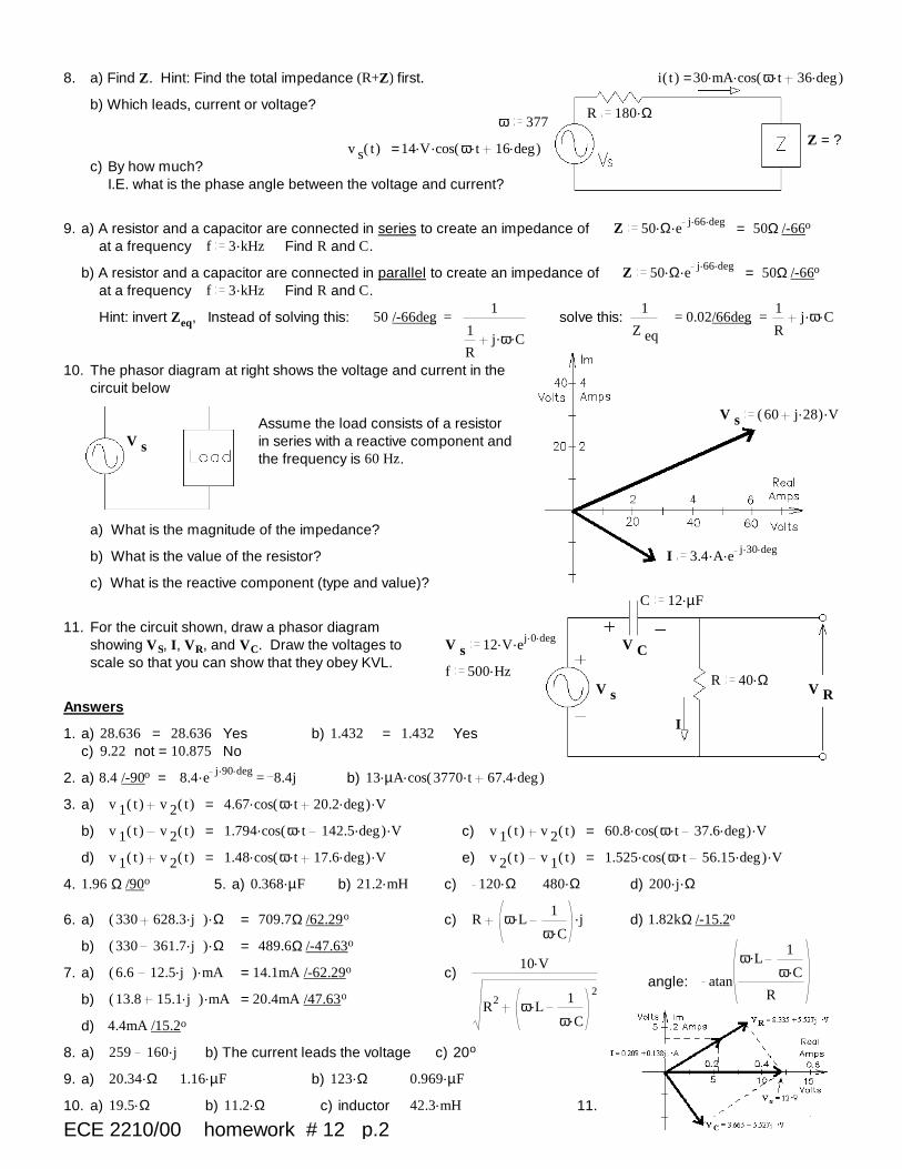
8. a) Find Z. Hint: Find the total impedance (R+Z) first. i( )t = ..30 mA cos( ).ω t .36 deg
b) Which leads, current or voltage?R .180 Ωω 377
Z = ?v s( )t = ..14 V cos( ).ω t .16 deg
c) By how much? I.E. what is the phase angle between the voltage and current?
9. a) A resistor and a capacitor are connected in series to create an impedance of Z ..50 Ω e..j 66 deg = 50Ω /-66o
at a frequency f .3 kHz Find R and C.
b) A resistor and a capacitor are connected in parallel to create an impedance of Z ..50 Ω e..j 66 deg = 50Ω /-66o
at a frequency f .3 kHz Find R and C.
Hint: invert Zeq, Instead of solving this: 50 /-66deg =1
1
R..j ω C
solve this:1
Z eq= 0.02/66deg =
1
R..j ω C
10. The phasor diagram at right shows the voltage and current in the circuit below
V s.( )60 .j 28 V
Assume the load consists of a resistor in series with a reactive component and the frequency is 60 Hz.
V s
a) What is the magnitude of the impedance?
b) What is the value of the resistor? I ..3.4 A e..j 30 deg
c) What is the reactive component (type and value)?C .12 µF
11. For the circuit shown, draw a phasor diagram showing VS, I, VR, and VC. Draw the voltages to scale so that you can show that they obey KVL.
V s..12 V e
..j 0 deg V C
f .500 HzR .40 Ω
V s V RAnswers
I1. a) 28.636 = 28.636 Yes b) 1.432 = 1.432 Yes
c) 9.22 not = 10.875 No
2. a) 8.4 /-90o = =.8.4 e..j 90 deg 8.4j b) ..13 µA cos( ).3770 t .67.4 deg
3. a) v 1( )t v 2( )t = ..4.67 cos( ).ω t .20.2 deg V
b) v 1( )t v 2( )t = ..1.794 cos( ).ω t .142.5 deg V c) v 1( )t v 2( )t = ..60.8 cos( ).ω t .37.6 deg V
d) v 1( )t v 2( )t = ..1.48 cos( ).ω t .17.6 deg V e) v 2( )t v 1( )t = ..1.525 cos( ).ω t .56.15 deg V
4. 1.96 Ω /90o 5. a) .0.368 µF b) .21.2 mH c) .120 Ω .480 Ω d) ..200 j Ω
6. a) .( )330 .628.3 j Ω = 709.7Ω /62.29o c) R ..ω L1.ω C
j d) 1.82kΩ /-15.2o
b) .( )330 .361.7 j Ω = 489.6Ω /-47.63o
7. a) .( )6.6 .12.5 j mA = 14.1mA /-62.29o c).10 V
R2 .ω L1.ω C
2angle: atan
.ω L1.ω C
Rb) .( )13.8 .15.1 j mA = 20.4mA /47.63o
d) 4.4mA /15.2o
8. a) 259 .160 j b) The current leads the voltage c) 20o
9. a) .20.34 Ω .1.16 µF b) .123 Ω .0.969 µF
10. a) .19.5 Ω b) .11.2 Ω c) inductor .42.3 mH 11.
ECE 2210/00 homework # 12 p.2

ECE 2210 / 00 homework # 13 ECE 2210 Due: Fri, 10/18/19 b.2
ECE 2200 Due: Fri, 10/4, may be handed in Fri, 10/18 for full creditThe 2nd exam will include this material
Warning: This homework is longer than normal -- DO NOT put it off until the last minute.
1. For the circuit shown, find the following:R .120 Ω
a) At what frequency would the magnitude of the total impedance be 240Ω?
L .3 mHb) At this frequency, what is the phase angle of the impedance?
c) At this frequency, you want to add a capacitor in series to make the circuit appear purely resistive (the impedance has no imaginary component). Find the value of the capacitor.
R .500 Ω2. You need to design a circuit in which the current (i(t))
leads the voltage (vS(t)) by 36o of phase. v S( )t = ..160 cos( ).450 t Vi( )t
a) What should go in the box: R, L, C?
b) Find its value.
.1.3 A I 13. The phasor diagram at right shows the source voltage and two branch currents of a parallel circuit. Find the inpedance of each of the two branches.
I 1 I 2
Z 1 Z 2 V SV S.1 A .50 V
I 2
4. a) Find all the currents, I1, I2, and IT .I T I 1 I 2
V S..24 V e
..j 45 deg
Z 1 Z 2 Z 2..250 Ω e
..j 45 deg
b) Draw a phasor diagram showing I1, I2, and IT to scale so that you can show that they obey KCL.
Z 1..100 Ω e
..j 10 deg
5. a) Find the AC current source, Iin in polar form. Z 1.( )120 .90 j Ω
b) Find VT.Z 1 V 1
.9 V
c) Choose one:
i) The source current leads the source voltage. V T
ii) The source current lags the source voltage.I in
Z 2 Z2 = 75 / 30o Ω
ECE 2210 homework # 13 p.1 Z 2..75 Ω e
..j 30 deg
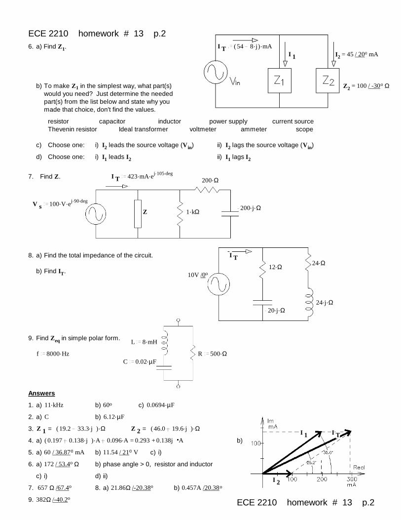
ECE 2210 homework # 13 p.26. a) Find Z1. I T
.( )54 .8 j mAI 1 I2 = 45 / 20o mA
b) To make Z1 in the simplest way, what part(s) would you need? Just determine the needed part(s) from the list below and state why you made that choice, don't find the values.
Z2 = 100 / -30o Ω
resistor capacitor inductor power supply current sourceThevenin resistor Ideal transformer voltmeter ammeter scope
c) Choose one: i) I2 leads the source voltage (Vin) ii) I2 lags the source voltage (Vin)
d) Choose one: i) I1 leads I2 ii) I1 lags I2
7. Find Z. I T..423 mA e
..j 105 deg.200 Ω
V s..100 V e
..j 90 deg..200 j Ω
Z .1 kΩ
8. a) Find the total impedance of the circuit. I T.24 Ω.12 Ω
b) Find IT. 10V /0o
..24 j Ω..20 j Ω
9. Find Zeq in simple polar form.L .8 mH
f .8000 Hz R .500 ΩC .0.02 µF
Answers
1. a) .11 kHz b) 60o c) .0.0694 µF
2. a) C b) .6.12 µF
3. Z 1 = .( )19.2 .33.3 j Ω Z 2 = .( )46.0 .19.6 j ΩI 1 I T
4. a) =.( )0.197 .0.138 j A .0.096 A 0.293 + 0.138j A b)
5. a) 60 / 36.87o mA b) 11.54 / 21o V c) i)
6. a) 172 / 53.4o Ω b) phase angle > 0, resistor and inductor
c) i) d) ii)I 2
7. 657 Ω /67.4o 8. a) 21.86Ω /-20.38o b) 0.457A /20.38o
9. 382Ω /-40.2o ECE 2210 homework # 13 p.2
Related Documents