Assessment of the feasibility of the possible joint use, on a long term basis, of the adjacent bands 5925-6425 MHz and 6425-7125 MHz for P-P links Approved May 2015 ECC Report 235

Welcome message from author
This document is posted to help you gain knowledge. Please leave a comment to let me know what you think about it! Share it to your friends and learn new things together.
Transcript
Assessment of the feasibility of the possible joint use, on a long term basis, of the adjacent bands 5925-6425 MHz and 6425-7125 MHz for P-P links
Approved May 2015
ECC Report 235
ECC REPORT 235 - Page 2
0 EXECUTIVE SUMMARY
The frequency bands 5925-6425 MHz and 6425-7125 MHz are used for Fixed Service (FS) with a large number of existing radio links within many CEPT countries. These links are used for variety of applications including broadcast distribution, mobile backhaul and infrastructure support for long distance communications. High capacity long distance radio links could be suitable to deploy in areas where optical fibre is not a realistic solution from an economical perspective. The “fibre like” capacity needed can be supported by using a wide channel arrangement, with channel bandwidths up to 112 MHz, in a contiguous frequency band between 5925-7125 MHz. A wider contiguous frequency band can also result in a better business case for operators due to investment in fewer transceivers (transmitter/receiver pairs) and other cost savings related to fewer antennas and leasing of less space in towers.
Some administrations may consider the introduction of new channel arrangements in the whole frequency range from 5925 to 7125 MHz, or are planning to re-structure their existing channel arrangements in this frequency range. This Report therefore studies the feasibility of merging the two adjacent frequency bands 5925-6425 MHz and 6425-7125 MHz into a single frequency band between 5925-7125 MHz on a long term basis for administrations national consideration. It is noted that this process is likely to include a number of considerations which may vary on a case by case basis and therefore a matter for the concerned administrations.
The study also considers that all existing channels in the 5925-6425 MHz (ERC/REC 14-01 [1]) and 6425-7125 MHz (ERC/REC 14-02 [2]) frequency bands cannot co-exist with all new channels in a combined 5925-7125 MHz frequency band at the same time over a path between the same sites. Therefore a compromise during the time of installation and period of restructuring will be required. It is common practice in P-P networks that a new frequency channel respects High/Low rule on shared sites for the same and adjacent frequency bands (e.g L6, U6 and 7 GHz). Violation of this rule limits the amount of usable spectrum and significantly reduces the future network expansion. Taking into account that several links of different operators can be deployed on a shared site, or both L6 and U6 bands are used simultaneously, it is possible that it will not be able for the transient period to preserve High/Low site consistency or to avoid spectral proximity of transmitting and receiving frequency of different links.
ECC/REC/(14)06 [5] also provides option for implementation of Fixed Service Point-to-Point narrow channels in the guard bands and center gaps of the existing lower 6 GHz (5925 to 6425 MHz) and upper 6 GHz (6425 to 7125 MHz) bands for administration consideration.
Special attention has also been given to studies of different co-existence scenarios and to find a possible solution. The study highlights the difference in Tx emission limits stated in EN 302 217-2-2 [9] and ETSI EN 302 217-2-1 [10]. Tx emission limits stated in EN 302 217-2-2, formally valid for CE assessment for all kind of equipment, are used in the main body of the Report in order to calculate Net Filter Discrimination (NFD) and finding a minimum required frequency separation between radio links using different channel arrangements. In ANNEX 2: the more stringent Tx limits stated in EN 302 217-2-1, typically valid only for indoor “multichannel trunk-like equipment”, are used, resulting in a lower required minimum frequency separation and an improved overall situation.
ECC REPORT 235 - Page 3
TABLE OF CONTENTS
0 EXECUTIVE SUMMARY ............................................................................................................................ 2
1 INTRODUCTION ......................................................................................................................................... 6
2 CURRENT AND FUTURE USE OF THE L6 AND U6 GHZ BANDS ......................................................... 7 2.1 Current FREQUENCY BAND PLAN FOR THE L6 and U6 GHz band ............................................. 7
2.1.1 Allocations in the L6 GHz and U6 GHz band .......................................................................... 8 2.2 Incentive for implementing wideband channel arrangements ........................................................... 8
2.2.1.1 Split mount configuration ....................................................................................... 10 2.2.1.2 Indoor Multichannel configuration ......................................................................... 11
2.3 POSSIBLE FUTURE USE OF THE 6 GHZ BAND .......................................................................... 12 2.3.1 Joint use L6 GHz, 5925-6425 MHz, and U6 GHz, 6425-7125 MHz, frequency bands ......... 12
3 COMPATIBILITY AND SHARING STUDIES ........................................................................................... 14 3.1 COMPATIBILITY/SHARING STUDIES IN THE 6 GHZ BAND ....................................................... 14
3.1.1 Introduction to compatibility and sharing studies ................................................................... 14 3.1.1.1 System Parameters ............................................................................................... 14
3.1.2 Sharing studies with other than FS service ........................................................................... 14 3.1.3 Sharing with Narrowband Fixed Service applications ........................................................... 14 3.1.4 Guard band and Centre Gap in the L6, U6 and new proposed 6 GHz band ........................ 15 3.1.5 Propagation model in 6 GHz frequency band ....................................................................... 15
3.2 Description of calculation methodology ........................................................................................... 15 3.2.1 NFD result .............................................................................................................................. 16 3.2.2 Required NFD and frequency separation .............................................................................. 16 3.2.3 Calculation of the wanted signal level ................................................................................... 17 3.2.4 Calculation of the interference signal level ............................................................................ 17 3.2.5 Calculation of Threshold Degradation ................................................................................... 17 3.2.6 Same Site Interference scenarios ......................................................................................... 18
3.2.6.1 Required NFD for co-located sites ........................................................................ 19 3.2.7 Different Site Interference scenarios ..................................................................................... 19
3.2.7.1 Required NFD for different sites ............................................................................ 20
4 RESTRUCTURING SCENARIOS............................................................................................................. 23 4.1 High/LOW site preservation ............................................................................................................ 23
4.1.1 Deployment of the new link on an unshared site ................................................................... 24 4.1.2 Deployment of the new link on a shared site ......................................................................... 25
4.1.2.1 Links from 7 GHz band only .................................................................................. 25 4.1.2.2 Links from L6 or U6 bands only ............................................................................ 25
4.1.3 Links from L6 or U6 bands and 7 GHz .................................................................................. 26 4.1.4 Links from L6 and U6 bands .................................................................................................. 26 4.1.5 Links from all concerned bands, i.e. L6, U6 and 7 GHz bands ............................................. 26
4.2 ONE STEP resturcturing ................................................................................................................. 27 4.3 TWO STEP restructuring ................................................................................................................. 29
4.3.1.1 First Step ............................................................................................................... 30 4.3.1.2 Second Step .......................................................................................................... 31
4.4 Summary of restructuring scenario ................................................................................................. 33
5 CONCLUSION .......................................................................................................................................... 34
ANNEX 1: NFD BASED ON ETSI EN 302 217-2-2 TX EMISSION MASKS ................................................. 35
ANNEX 2: RESTRUCTURING SCENARIO USING ETSI EN 302 217-2-1 TX EMISSION MASK ............... 36

ECC REPORT 235 - Page 4
ANNEX 3: ANALYSIS ON NFD TO BE USED IN THE RESTRUCTURING STRATEGY ............................. 38
ANNEX 4: CALCULATION OF REQUIRED NFD .......................................................................................... 41
ANNEX 5: CURRENT L6 AND U6 GHZ P-P USAGE IN CEPT COUNTRIES .............................................. 47
ANNEX 6: CHANNEL ARRANGEMENT EXAMPLE (5925-7125 MHZ) USED IN THIS REPORT. .............. 53
ANNEX 7: LIST OF REFERENCE .................................................................................................................. 54
ECC REPORT 235 - Page 5
LIST OF ABBREVIATIONS Abbreviation ACDP Adjacent Channel Dual Polarisation AM Adaptive Modulation AMR Adaptive Multi-Rate ATPC Automatic Transmit Power Control CCDP Co Channel Dual Polarisation CEPT European Conference of Postal and Telecommunications Administrations. ECC Electronic Communications Committee. ETSI European Telecommunications Standards Institute FS Fixed Service FSS Fixed Satellite Services HS Harmonised Standard IDU Indoor Unit ITU-R International Telecommunication Union - Radiocommunication Sector L6 GHz Lower 6 GHz frequency band, 5925-6425 MHz, with channel arrangement in
accordance with CEPT/ERC Recommendation 14-01 E [1]. U6 GHz
Upper 6 GHz frequency band, 6425-7125 MHz, with channel arrangement in accordance with CEPT/ERC Recommendation 14-01 E [2].
6 GHz
6 GHz frequency band, 5925-7125 MHz, new channel arrangement in a combination of the two adjacent L6 GHz and U6 GHz frequency bands.
NFD Net Filter Discrimination, The NFD express the reduction (in dB) of the interference power caused by the filtering shape of the transmitter emission mask and the receiver selectivity mask
ODU Outdoor Unit P-P Point to Point R&TTE Radio equipment and Telecommunications Terminal Equipment Rx Receiver STM Synchronous Transfer Mode TBD To be decided TD Threshold Degradation Tx Transmitter XPIC Cross-Polarization Interference Cancelation
ECC REPORT 235 - Page 6
1 INTRODUCTION
In order to assess the feasibility of joint use, on a long term basis, of the adjacent bands 5925-6425 MHz and 6425-7125 MHz for P-P links, it has been suggested to study the following with focus on the last bullet point.
Narrowband FS services implementation in the centre gap and guard band of today’s L6 GHz and U6 GHz channel plans;
Fixed Satellite Services (FSS Earth stations) with allocation in the lower half of the L6 GHz band; Co-existence with existing channel plans until implementation of a new channel plan is possible
ECC REPORT 235 - Page 7
2 CURRENT AND FUTURE USE OF THE L6 AND U6 GHZ BANDS
2.1 CURRENT FREQUENCY BAND PLAN FOR THE L6 AND U6 GHZ BAND
The bands 5925 MHz to 7125 MHz are allocated to Fixed Service among other services on primary basis in all regions as shown in Table 1.
Table 1: Table of Allocation in 5925 MHz – 7145 MHz (source Radio Regulations 2012)
The 6 GHz frequency band is suitable for applications such as infrastructure support where longer paths are required.
According to ECC Report 173, the 5.9 – 7.1 GHz range is used in Europe for high capacity P-P links, in accordance with the frequency plans contained in the ERC/REC 14-01 and ERC/REC 14-02, mainly forming part of fixed and mobile and broadcasting infrastructure.
The results of the questionnaire for the whole 31 CEPT countries indicated 20242 links declared active in this range, which has been traditionally used for P-P links since quite a long time.
In 2011, significant number of countries indicated a moderate trend to increase the usage of this range in the years to come (10 to 30% increase), some reported even a higher percentage, some other indicated the band is congested or close to congestion.
Currently, existing equipment are based upon the following channel plans:
CEPT/ERC/REC 14-01 E [1] (Bonn 1995, revised June 2007) provides the channel arrangements for the lower 6 GHz band (5925-6425 MHz), with the old channel spacing of 29.65 MHz;
CEPT/ERC/REC 14-02 E [2] (Bonn 1995, Revised Dublin 2009) provides the channel arrangements for the upper 6 GHz band (6425-7125 MHz), with 6 different channel spacings (40, 30, 20, 14, 7, 3.5 MHz);
Recommendation ITU-R F.383-9 (02/2013) [3] Radio-frequency arrangements for high-capacity wireless systems operating in the lower 6 GHz (5925 to 6425 MHz), with channel spacing of 5, 10, 20, 28, 29.65, 40 and 80 MHz;
Recommendation ITU-R F.384-11 (03/2012) [4] Radio-frequency arrangements for medium and high-capacity digital fixed wireless systems operating 6425-7125 MHz band, with channel spacing of 3.5, 5, 7, 10, 14, 20, 30, 40 MHz;
CEPT/ECC/REC/(14)06 [5] provides the channel arrangements for implementation of Fixed Service Point-to-Point narrow channels (3.5 MHz, 1.75 MHz, 0.5 MHz, 0.25 MHz, 0.025 MHz) in the guard bands and centre gaps of the lower 6 GHz (5925-6425 MHz) and upper 6 GHz (6425-7125 MHz) bands.
Allocation to services
Region 1 Region 2 Region 3
5 925-6 700 FIXED 5.457 FIXED-SATELLITE (Earth-to-space) 5.457A 5.457B MOBILE 5.457C 5.149 5.440 5.458
6 700-7 075 FIXED FIXED-SATELLITE (Earth-to-space) (space-to-Earth) 5.441 MOBILE 5.458 5.458A 5.458B 5.458C 7 075-7 145 FIXED MOBILE 5.458 5.459
ECC REPORT 235 - Page 8
Due to a variety of options with regard to channel spacing, the degree of harmonisation could be improved in this band on a long term basis. In addition, more capacity, mainly in rural areas where optical fibre is not an economical solution, will be needed in future infrastructure systems.
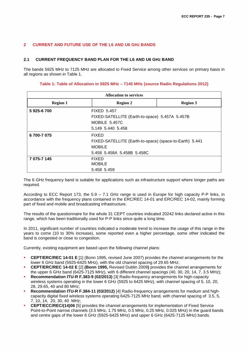
Figure 1 below presents the recommended frequency band plan for the L6 GHz, ERC/REC 14-01 [1].
Figure 1: Channel arrangement in the 5925-6425 MHz band with 29.65 MHz channel separation
For wider channels bandwidth than the eight 29.65 MHz channels available, there is an option to pair 29.65 MHz channels into 59.3 MHz channel, for a total of four 59.3 MHz channels. However, this option does not provide a harmonised solution.
Figure 2 below presents the recommended frequency band plan for the U6 GHz, ERC/REC14-02 [2].
Figure 2: Channel arrangement in the 6425-7125 MHz band with 40 MHz channel separation
For wider channels bandwidth than the eight 40 MHz channels available, there is an option to pair 40 MHz channels into an 80 MHz channel, for a total of four 80 MHz channels.
2.1.1 Allocations in the L6 GHz and U6 GHz band
Existing usage and allocations are described in ECC Report 215 [6].
2.2 INCENTIVE FOR IMPLEMENTING WIDEBAND CHANNEL ARRANGEMENTS
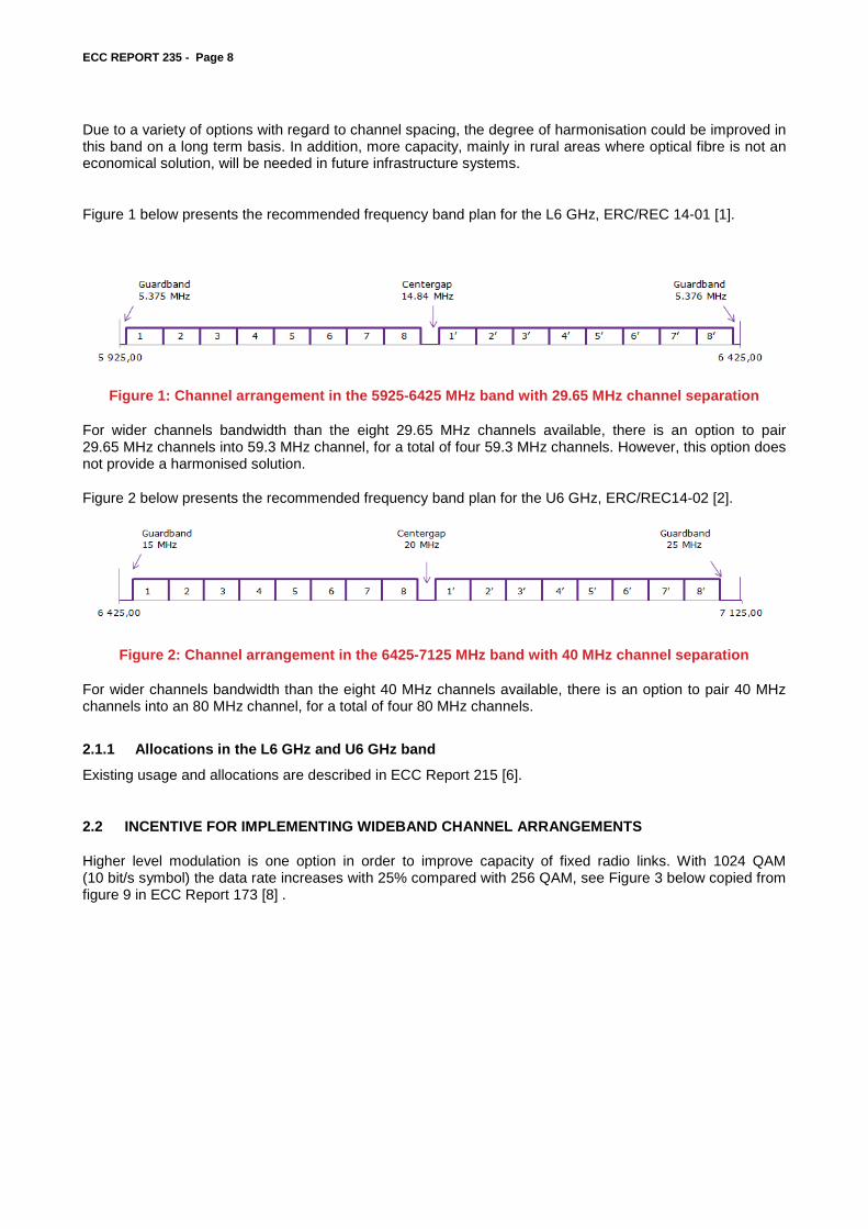
Higher level modulation is one option in order to improve capacity of fixed radio links. With 1024 QAM (10 bit/s symbol) the data rate increases with 25% compared with 256 QAM, see Figure 3 below copied from figure 9 in ECC Report 173 [8] .
ECC REPORT 235 - Page 9
Figure 3: Spectral Efficiency versus modulation level (example for CS=28 MHz and symbol frequency of around 0.9CS)
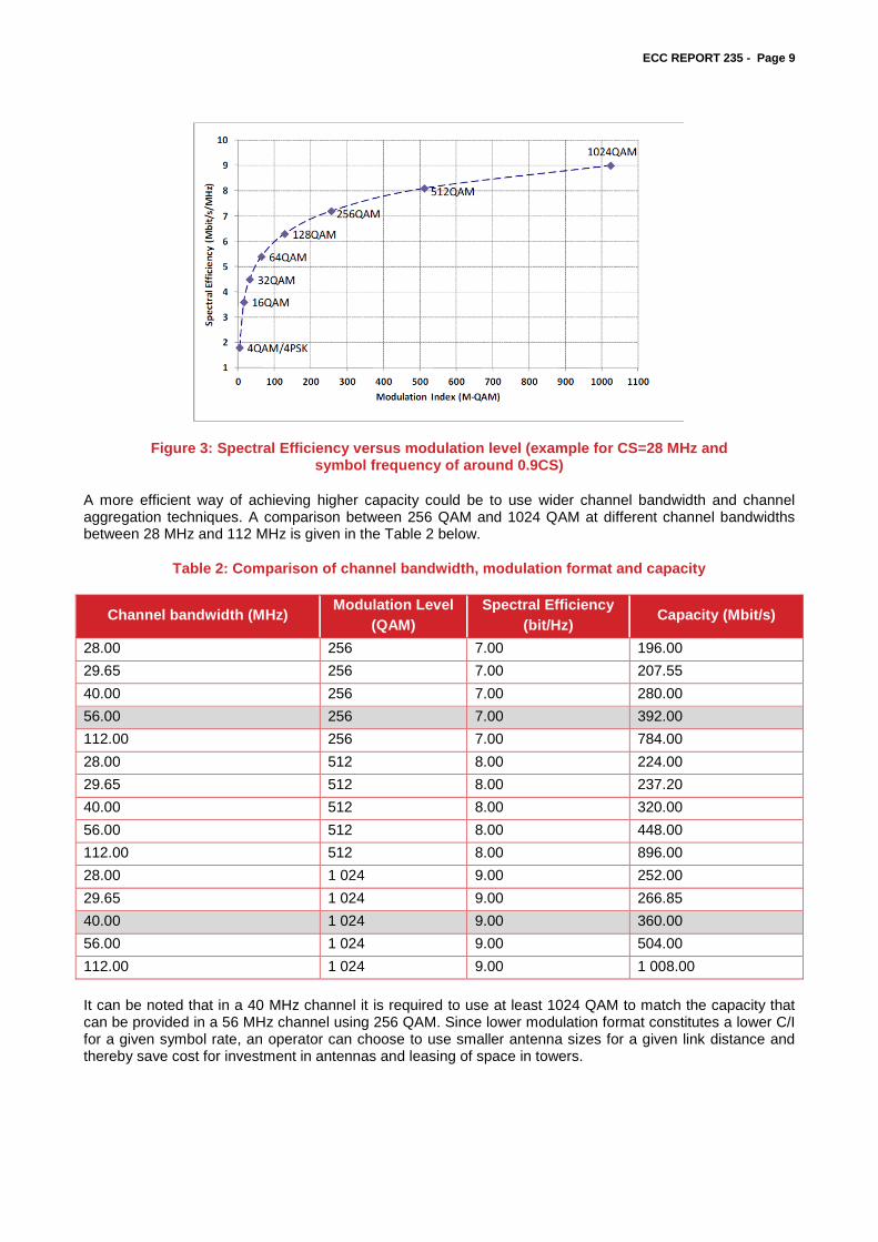
A more efficient way of achieving higher capacity could be to use wider channel bandwidth and channel aggregation techniques. A comparison between 256 QAM and 1024 QAM at different channel bandwidths between 28 MHz and 112 MHz is given in the Table 2 below.
Table 2: Comparison of channel bandwidth, modulation format and capacity
Channel bandwidth (MHz) Modulation Level (QAM)
Spectral Efficiency (bit/Hz)
Capacity (Mbit/s)
28.00 256 7.00 196.00 29.65 256 7.00 207.55 40.00 256 7.00 280.00 56.00 256 7.00 392.00 112.00 256 7.00 784.00 28.00 512 8.00 224.00 29.65 512 8.00 237.20 40.00 512 8.00 320.00 56.00 512 8.00 448.00 112.00 512 8.00 896.00 28.00 1 024 9.00 252.00 29.65 1 024 9.00 266.85 40.00 1 024 9.00 360.00 56.00 1 024 9.00 504.00 112.00 1 024 9.00 1 008.00 It can be noted that in a 40 MHz channel it is required to use at least 1024 QAM to match the capacity that can be provided in a 56 MHz channel using 256 QAM. Since lower modulation format constitutes a lower C/I for a given symbol rate, an operator can choose to use smaller antenna sizes for a given link distance and thereby save cost for investment in antennas and leasing of space in towers.
ECC REPORT 235 - Page 10
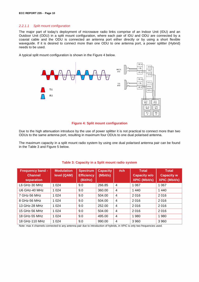
2.2.1.1 Split mount configuration
The major part of today’s deployment of microwave radio links comprise of an Indoor Unit (IDU) and an Outdoor Unit (ODU) in a split mount configuration, where each pair of IDU and ODU are connected by a coaxial cable and the ODU is connected an antenna port either directly or by using a short flexible waveguide. If it is desired to connect more than one ODU to one antenna port, a power splitter (Hybrid) needs to be used.
A typical split mount configuration is shown in the Figure 4 below.
Figure 4: Split mount configuration
Due to the high attenuation introduce by the use of power splitter it is not practical to connect more than two ODUs to the same antenna port, resulting in maximum four ODUs to one dual polarised antenna.
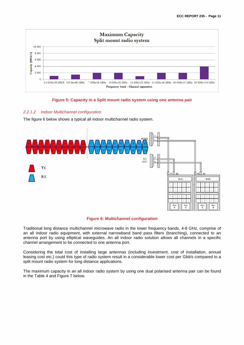
The maximum capacity in a split mount radio system by using one dual polarised antenna pair can be found in the Table 3 and Figure 5 below.
Table 3: Capacity in a Split mount radio system
Frequency band - Channel
separation
Modulation level (QAM)
Spectrum Efficiency
(Bit/Hz)
Capacity (Mbit/s)
#ch Total Capacity w/o XPIC (Mbit/s)
Total Capacity w
XPIC (Mbit/s) L6 GHz-30 MHz 1 024 9.0 266.85 4 1 067 1 067 U6 GHz-40 MHz 1 024 9.0 360.00 4 1 440 1 440 7 GHz-56 MHz 1 024 9.0 504.00 4 2 016 2 016 8 GHz-56 MHz 1 024 9.0 504.00 4 2 016 2 016 13 GHz-28 MHz 1 024 9.0 252.00 4 2 016 2 016 15 GHz-56 MHz 1 024 9.0 504.00 4 2 016 2 016 18 GHz-55 MHz 1 024 9.0 495.00 4 1 980 1 980 18 GHz-110 MHz 1 024 9.0 990.00 4 3 960 3 960 Note: max 4 channels connected to any antenna pair due to introduction of hybrids, in XPIC is only two frequencies used.
ECC REPORT 235 - Page 11
Figure 5: Capacity in a Split mount radio system using one antenna pair
2.2.1.2 Indoor Multichannel configuration
The figure 6 below shows a typical all indoor multichannel radio system.
Figure 6: Multichannel configuration
Traditional long distance multichannel microwave radio in the lower frequency bands, 4-8 GHz, comprise of an all indoor radio equipment, with external narrowband band pass filters (branching), connected to an antenna port by using elliptical waveguides. An all indoor radio solution allows all channels in a specific channel arrangement to be connected to one antenna port.
Considering the total cost of installing large antennas (including investment, cost of installation, annual leasing cost etc.) could this type of radio system result in a considerable lower cost per Gbit/s compared to a split mount radio system for long distance applications.
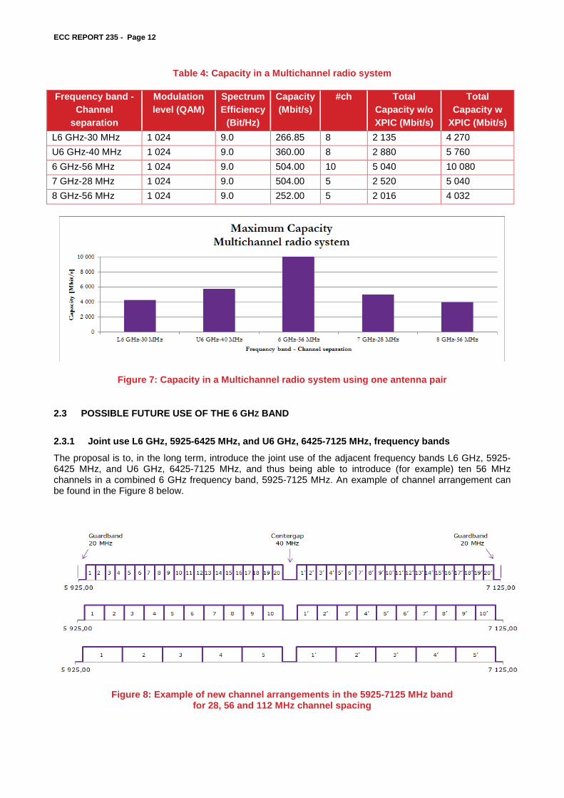
The maximum capacity in an all indoor radio system by using one dual polarised antenna pair can be found in the Table 4 and Figure 7 below.
ECC REPORT 235 - Page 12
Table 4: Capacity in a Multichannel radio system
Frequency band - Channel
separation
Modulation level (QAM)
Spectrum Efficiency
(Bit/Hz)
Capacity (Mbit/s)
#ch Total Capacity w/o XPIC (Mbit/s)
Total Capacity w
XPIC (Mbit/s) L6 GHz-30 MHz 1 024 9.0 266.85 8 2 135 4 270 U6 GHz-40 MHz 1 024 9.0 360.00 8 2 880 5 760 6 GHz-56 MHz 1 024 9.0 504.00 10 5 040 10 080 7 GHz-28 MHz 1 024 9.0 504.00 5 2 520 5 040 8 GHz-56 MHz 1 024 9.0 252.00 5 2 016 4 032
Figure 7: Capacity in a Multichannel radio system using one antenna pair
2.3 POSSIBLE FUTURE USE OF THE 6 GHZ BAND
2.3.1 Joint use L6 GHz, 5925-6425 MHz, and U6 GHz, 6425-7125 MHz, frequency bands
The proposal is to, in the long term, introduce the joint use of the adjacent frequency bands L6 GHz, 5925-6425 MHz, and U6 GHz, 6425-7125 MHz, and thus being able to introduce (for example) ten 56 MHz channels in a combined 6 GHz frequency band, 5925-7125 MHz. An example of channel arrangement can be found in the Figure 8 below.
Figure 8: Example of new channel arrangements in the 5925-7125 MHz band for 28, 56 and 112 MHz channel spacing
ECC REPORT 235 - Page 13
Since both the L6 GHz and U6 GHz band comprise of eight 29.65 and eight 40 MHz radio channels each, respectively, it is required to invest in up to (2x8+2x8) 32 radios for a fully loaded XPIC radio terminal using both the L6 and U6 GHz bands. When using a joint 6 GHz band comprising of ten 56 MHz radio channels it is required to invest in up to 20 radios for a fully loaded XPIC radio terminal, a reduction of the number of radios with 38% could contribute further to cost reductions.
The detailed channel arrangements used for drawing the conclusion of this report can be found in Annex 6.
ECC REPORT 235 - Page 14
3 COMPATIBILITY AND SHARING STUDIES
3.1 COMPATIBILITY/SHARING STUDIES IN THE 6 GHZ BAND
3.1.1 Introduction to compatibility and sharing studies
All existing channels in the L6 GHz or U6 GHz frequency band cannot co-exist with all new channels in the combined 6 GHz frequency band at the same time over a path between the same sites. A compromise during the time of installation and implementation is required and the questions is to evaluate if the achievable result is acceptable or not from an operator point of view. Modern radio systems give, in comparison with previous equipment generations, the access to new functions such as;
Automatic Power Control (ATPC); Adaptive Modulation (AM); Adjustable channel bandwidth, remotely changeable/controlled. Each and every of the above functions could facilitate the implementation from an older channel plan into a new channel plan with a different duplex distance by keeping the transmitted power to a minimum but still being able to guarantee transmission of the prioritized traffic.
3.1.1.1 System Parameters
The systems parameters used to asses potential interference for P-P FS system operating in the L6 GHz and U6 GHz frequency bands can be found in Recommendation ITU-R F.758-5 [7] . The system parameters for a P-P FS system operating in a new 6 GHz channel arrangement could be considered to be similar as the systems parameters for radio systems operating the L6 GHz and U6 GHz frequency bands, the only major difference being the duplex distance and channel bandwidths.
3.1.2 Sharing studies with other than FS service
Sharing studies with other services have been thoroughly carried out in ECC Report 215 [6]. Those results are considered valid also for new radio system working in the combined 6 GHz band.
3.1.3 Sharing with Narrowband Fixed Service applications
Given the introduction of narrowband Fixed Services as described in ECC Report 215 [6] and ECC/REC/(14)06 [5] it may be an advantage if the narrowband radio systems could be tuned into any new centre gap and guard bands within the frequency range 5925-7125 MHz whenever the administrations consider the new wideband channel plan options.
Initial installations of Narrowband Fixed Services should focus on the existing guard band in the upper part of U6 GHz channel plan. When a possible new channel plan has been developed the new centre gap can be used as well.
In addition, the suggested new 6 GHz channel arrangement allows more contiguous spectrum for narrow band services compared to existing channel arrangements.
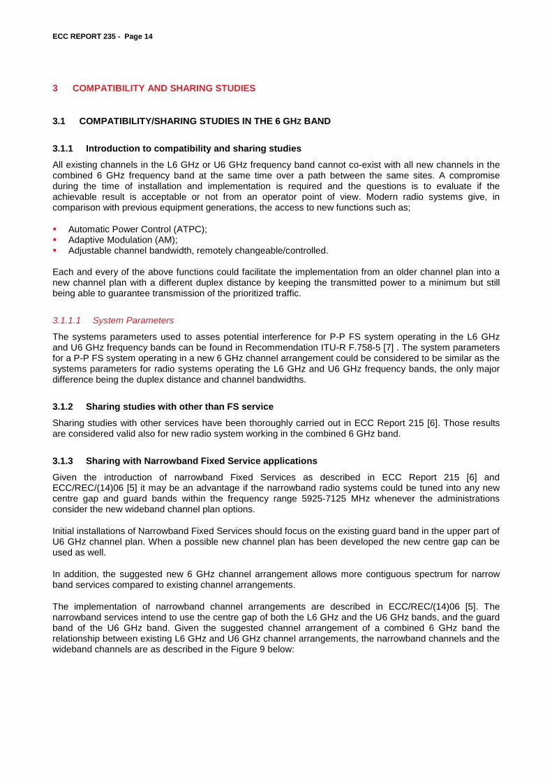
The implementation of narrowband channel arrangements are described in ECC/REC/(14)06 [5]. The narrowband services intend to use the centre gap of both the L6 GHz and the U6 GHz bands, and the guard band of the U6 GHz band. Given the suggested channel arrangement of a combined 6 GHz band the relationship between existing L6 GHz and U6 GHz channel arrangements, the narrowband channels and the wideband channels are as described in the Figure 9 below:
ECC REPORT 235 - Page 15
Figure 9: Comparison between narrowband and wideband channels in the 6 GHz
Given that narrowband services have been deployed in the same area as wideband services, and that no additional protection between the two services can be added due to antenna directivity, the worst case scenario in case of 28 MHz channel separation in the new 6 GHz channel arrangement is that channels 9 and 18 in the lower part of the band cannot be used due to added interference to, and from, the narrowband services. In the upper part of the band the unusable channels are 8’ and 9’.
The conclusion is that the worst case scenario, compared to existing separate L6 and U6 GHz band, is that three out of twenty 28 MHz channels (15% of the spectrum) cannot be used in the same geographical area given that narrowband services are deployed in the centre gaps and guards bands of the existing L6 and U6 GHz bands in accordance with ECC/REC/(14)06 [5].
3.1.4 Guard band and Centre Gap in the L6, U6 and new proposed 6 GHz band
The proposed new channel plan extends the existing guard band in the L6 GHz from 5.375 MHz to 20 MHz, see Table 5 below.
Table 5: Guard band and centre gaps
L6 GHz U6 GHz 6 GHz Guard Band 5375+5385 MHz 15+25 MHz 2x20 MHz Centre Gap 14.84 MHz 20 MHz 40 MHz
3.1.5 Propagation model in 6 GHz frequency band
Free space model describes the theoretical minimum propagation path loss between transmitter and receiver when direct line of sight (LOS) is assumed (earth curvature is not taken into consideration)
The following model is used for frequencies above 30 MHz
)log(2044,32][ dfdBFSL ×+=
where f is the frequency in MHz and d is the distance between transmitter and receiver in km.
3.2 DESCRIPTION OF CALCULATION METHODOLOGY
The calculation method to be used should correspond to a method that operators easily can reproduce in their own radio planning tools. The proposed method of calculating interference level is by the use of Net Filter Discrimination (NFD) The NFD express the reduction (in dB) of the interference power caused by the filtering shape of the transmitter emission mask and the receiver selectivity mask.
5 925,00 7 125,00
5 925,00 7 125,00
5 925,00 7 125,00
L6G U6G
Narrowband L6 Narrowband U6
6G
1 2 3 4 5 6 7 8 1’ 2’ 3’ 4’ 5’ 6’ 7’ 8’ 1 2 3 4 5 6 7 8 1’ 2’ 3’ 4’ 5’ 6’ 7’ 8’
1 2 3 4 5 6 7 8 9 10 11 12 13 14 15 16 17 18 19 20 1’ 2’ 3’ 4’ 5’ 6’ 7’ 8’ 9’ 10’ 11’ 12’ 13’ 14’ 15’ 16’ 17’ 18’ 19’ 20’
ECC REPORT 235 - Page 16
3.2.1 NFD result
In this report are NFD values presented based on the Tx emission limits as stated in ETSI EN 302 217-2-2 V2.2.0 (2013-11). The NFD for various transmitter and receiver combinations under consideration, at different channel separations 28, 40 and 56 MHz, with Tx emission mask in accordance with ETSI EN 302 217-2-2 [9], can be found in Annex 1.
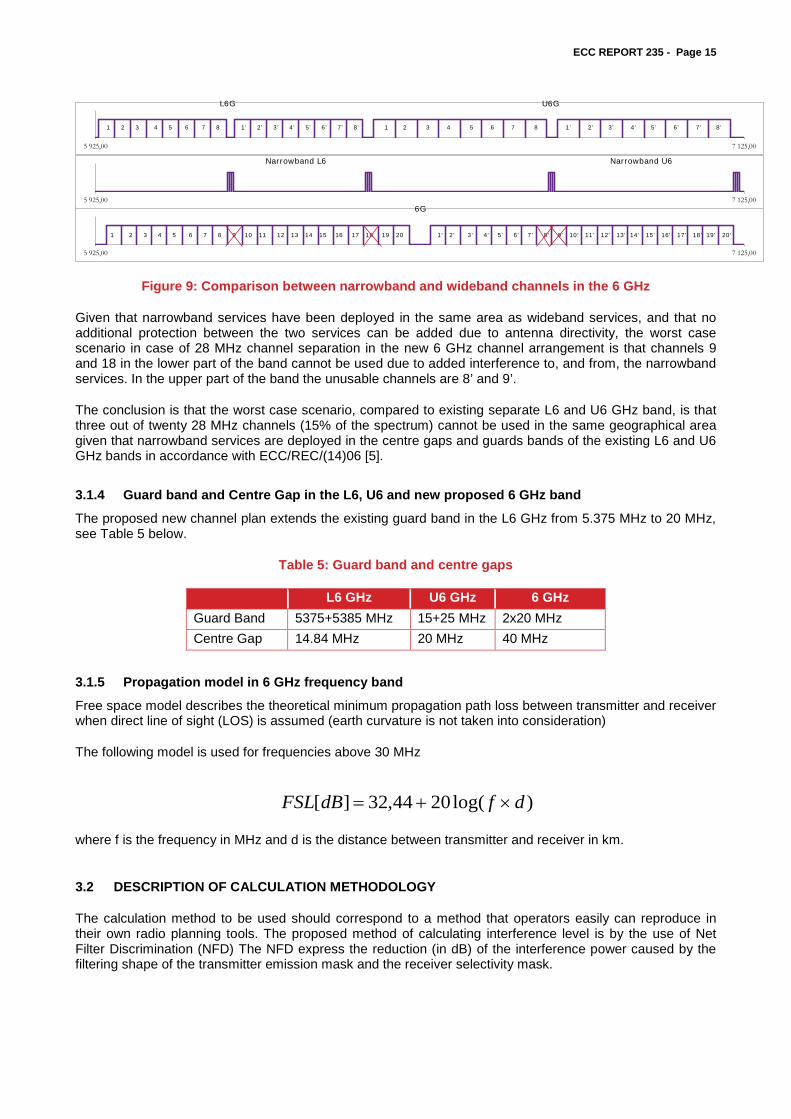
A summary of the results based on ETSI EN 302 217-2-2 can be found in the Figure 10 below:
Figure 10: NFD as a function of frequency offset for various Tx and Rx combinations using ETSI 302 217-2-2 Tx emission limits
A typical radio system will have a significantly better Tx emission and Rx selectivity performance than the ones stated in ETSI EN 302 217-2-2 and consequently it should be noted that using existing ETSI 302 217-2-2 Tx emission limits could result in a very conservative NFD value compared to actual radio systems.
For reference can examples of the more stringent NFD values based on ETSI EN 302 217-2-1 [10] be found in Annex 2.
Additional information regarding impact of Hardware design upon NFD can be found in Annex 3.
3.2.2 Required NFD and frequency separation
Normally only 1 or 3 dB Threshold Degradation is acceptable, but a higher interference level could be acceptable during a period of change (during a non-fading part of the season) depending on the operator’s quality and availability requirements. The level of interference, resulting in receiver threshold degradation and lower fade margins, should be considered together with the predicted performance and availability for each individual link.
The NFD required sets the minimum frequency separation necessary to keep threshold degradation below an acceptable level.
0,00
10,00
20,00
30,00
40,00
50,00
60,00
0 20 40 60 80 100 120
Net
Filt
er D
iscr
imin
atio
n (d
B)
Frequency offset (MHz)
TX 28 MHz RX 28 MHz
TX 28 MHz RX 40 MHz
TX 28 MHz RX 56 MHz
TX 40 MHz RX 40 MHz
TX 40 MHz RX 28 MHz
TX 40 MHz RX 56 MHz
TX 56 MHz RX 56 MHz
TX 56 MHz RX 28 MHz

ECC REPORT 235 - Page 17
3.2.3 Calculation of the wanted signal level
Using the free space model under the assumption that there is direct line-of-sight (LOS) between the transmitter and the receiver sites, the wanted free space receiver input level, Pr0, can be calculated as follows:
Pr0 = Pt + Gt - 32,44 - 20log(f x d) + Gr [dBm] (eq.1)
where:
Pt – Transmitter power at antenna port [dBm] Gt – Transmitter antenna gain [dBi] f – Radio carrier frequency [MHz] d – Distance between transmitter and receiver [km] Gr – Receiver antenna gain [dBi]
3.2.4 Calculation of the interference signal level
The unwanted interference power at receiver input, Ir, can be calculated as follows:
Ir = Pt + Gt(α) - 32,44 - 20log(f x d) + Gr(β) – NFD [dBm] (eq.2)
where:
Pt – Transmitter power at antenna port [dBm] Gt(α) – Transmitter off axis antenna gain in direction α towards the receiver [dBi] f – Radio carrier frequency [MHz] d – Distance between transmitter and receiver [km] Gr(β) – Receiver off axis antenna gain in direction β towards the transmitter [dBi] NFD – Net Filter Discrimination [dB]
3.2.5 Calculation of Threshold Degradation
A Received Signal Level of a radio systems receiver is the minimum level of the wanted signal for a given Bit Error Rate (BER). ECC/REC/(01)05 (recommends 1) [14] define the threshold degradation of a victim receiver as the increase of the noise power in the receiver bandwidth resulting from the aggregation of all interference coming from the relevant sources of the fixed service, weighted by the victim receiver selectivity. Typical radio budget links plan a degradation of the interference margin (i.e. 1 dB or 3 dB for a single or aggregate interferer respectively) with no impact on the BER. An increase of the interfering signal level beyond these values, will result in a lower fade margin.
In order to calculate the TD must first the noise power, Pnoise, in the interfered receiver bandwidth be calculated as follows
Pnoise = 10log(kTB) + F + 90 [dBm] (eq.3) where: k – Bolzmann’s constant (k=1,38*10-23 ) [W/K/Hz] T – Equivalent Noise Temperature [K] B – Effective receiver bandwidth [MHz] F – Receiver noise figure [dB] The TD can then be calculated as follows. 𝑇𝑇𝑇𝑇 = 10𝑙𝑙𝑙𝑙𝑙𝑙�1 + 10(𝐼𝐼𝑟𝑟𝑟𝑟−𝑃𝑃𝑛𝑛𝑛𝑛𝑛𝑛𝑛𝑛𝑛𝑛)/10� [dB] (eq.4)
ECC REPORT 235 - Page 18
3.2.6 Same Site Interference scenarios
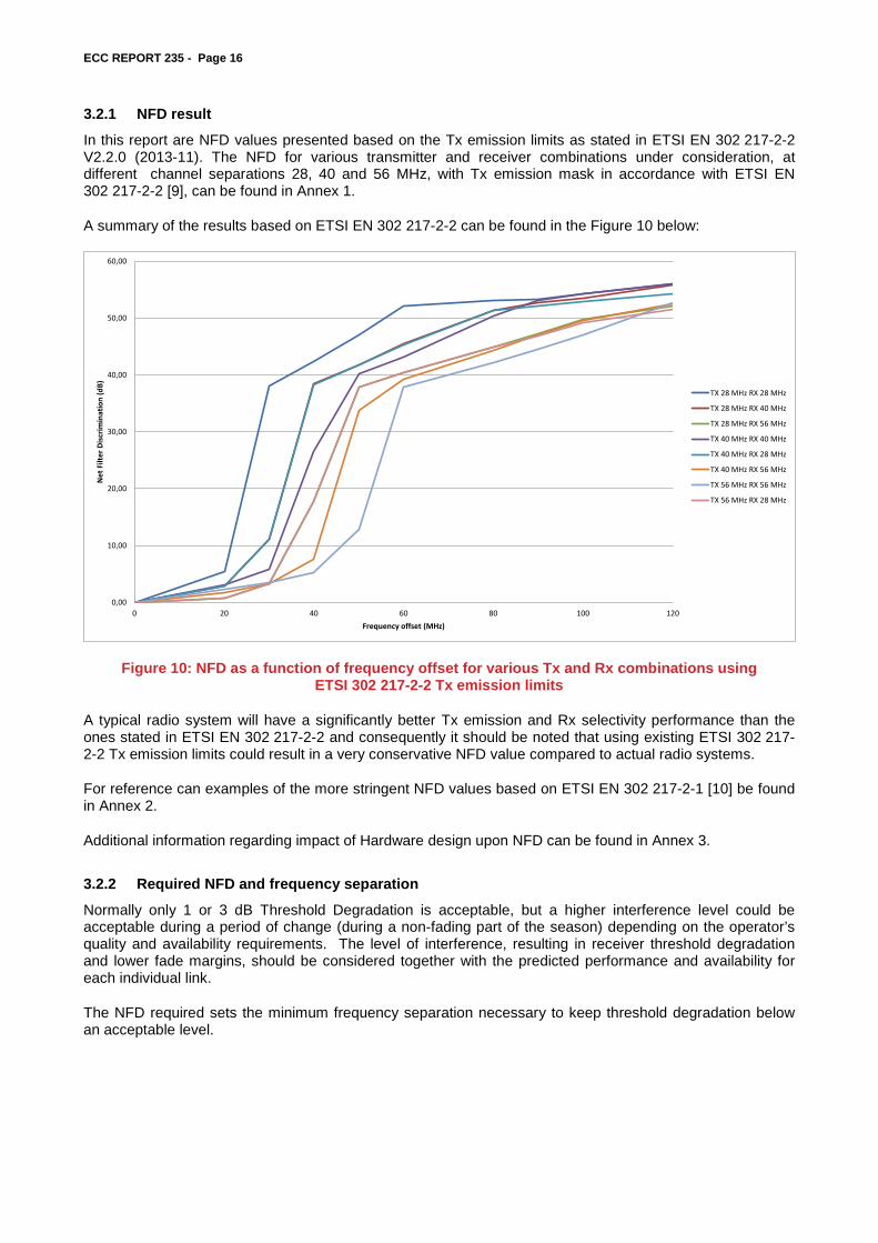
The following same site scenarios have been considered:
The worst case to be considered is when the new radio system shares the same sites as the previous system, see Figure 11, thus not being able to account for any antenna attenuation other than XPD. This will also simplify the calculations since both systems share the same path and will have the same path propagation loss and to some extent also experience the same amount of fading, even though not correlated. This worst case scenario gives an indication on the level of co-existence that can be achieved.
Figure 11: Co-located sites sharing the same path
The scenario could be considered when an operator wants to upgrade of an existing network and reinvest in a new radio system with higher capacity. Since the two radio systems typically are operated by the same operator it might be acceptable for the same operator to allow a higher interference level and threshold degradation during time of installation. This scenario normally takes place within the borders of one country and it is therefore up to each national Administration to decide upon provisional threshold degradation.
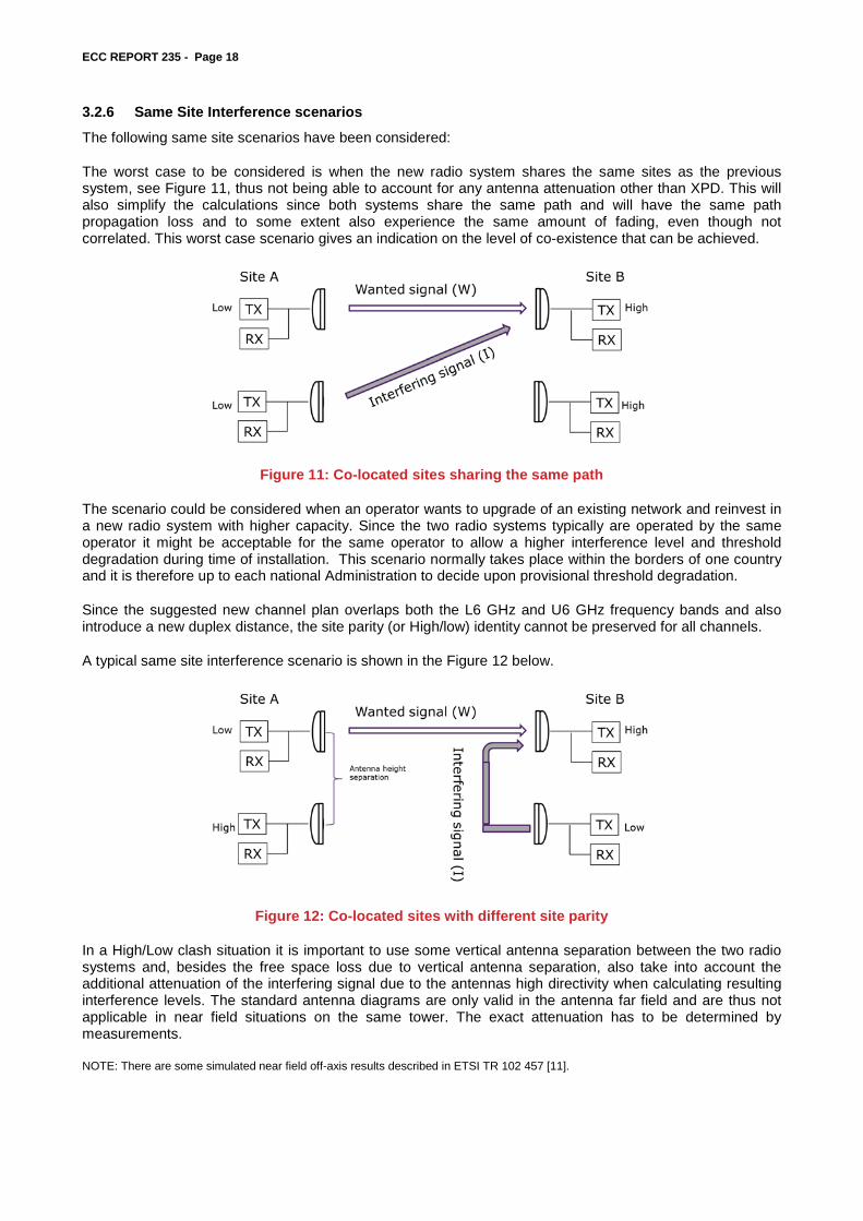
Since the suggested new channel plan overlaps both the L6 GHz and U6 GHz frequency bands and also introduce a new duplex distance, the site parity (or High/low) identity cannot be preserved for all channels.
A typical same site interference scenario is shown in the Figure 12 below.
Figure 12: Co-located sites with different site parity
In a High/Low clash situation it is important to use some vertical antenna separation between the two radio systems and, besides the free space loss due to vertical antenna separation, also take into account the additional attenuation of the interfering signal due to the antennas high directivity when calculating resulting interference levels. The standard antenna diagrams are only valid in the antenna far field and are thus not applicable in near field situations on the same tower. The exact attenuation has to be determined by measurements.
NOTE: There are some simulated near field off-axis results described in ETSI TR 102 457 [11].
ECC REPORT 235 - Page 19
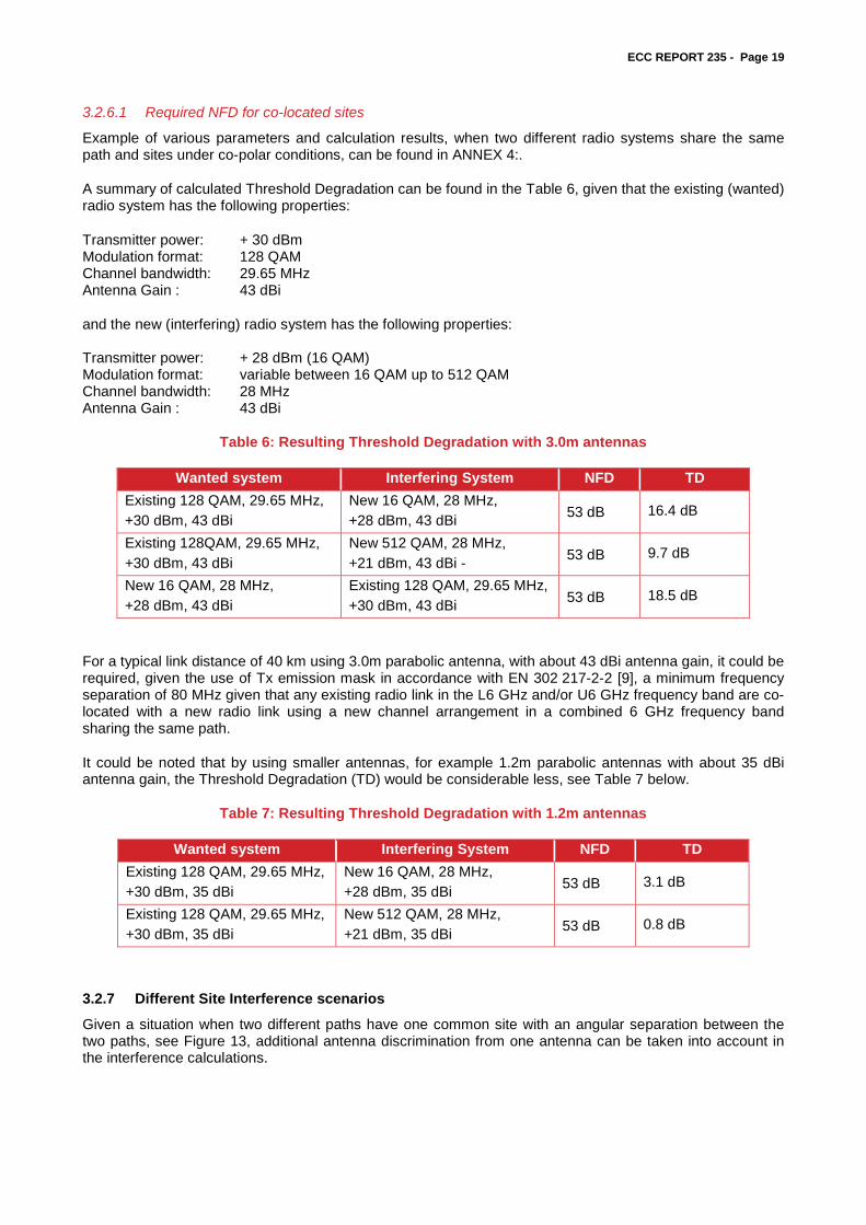
3.2.6.1 Required NFD for co-located sites
Example of various parameters and calculation results, when two different radio systems share the same path and sites under co-polar conditions, can be found in ANNEX 4:.
A summary of calculated Threshold Degradation can be found in the Table 6, given that the existing (wanted) radio system has the following properties:
Transmitter power: + 30 dBm Modulation format: 128 QAM Channel bandwidth: 29.65 MHz Antenna Gain : 43 dBi
and the new (interfering) radio system has the following properties: Transmitter power: + 28 dBm (16 QAM) Modulation format: variable between 16 QAM up to 512 QAM Channel bandwidth: 28 MHz Antenna Gain : 43 dBi
Table 6: Resulting Threshold Degradation with 3.0m antennas
Wanted system Interfering System NFD TD Existing 128 QAM, 29.65 MHz, +30 dBm, 43 dBi
New 16 QAM, 28 MHz, +28 dBm, 43 dBi 53 dB 16.4 dB
Existing 128QAM, 29.65 MHz, +30 dBm, 43 dBi
New 512 QAM, 28 MHz, +21 dBm, 43 dBi - 53 dB 9.7 dB
New 16 QAM, 28 MHz, +28 dBm, 43 dBi
Existing 128 QAM, 29.65 MHz, +30 dBm, 43 dBi 53 dB 18.5 dB
For a typical link distance of 40 km using 3.0m parabolic antenna, with about 43 dBi antenna gain, it could be required, given the use of Tx emission mask in accordance with EN 302 217-2-2 [9], a minimum frequency separation of 80 MHz given that any existing radio link in the L6 GHz and/or U6 GHz frequency band are co-located with a new radio link using a new channel arrangement in a combined 6 GHz frequency band sharing the same path.
It could be noted that by using smaller antennas, for example 1.2m parabolic antennas with about 35 dBi antenna gain, the Threshold Degradation (TD) would be considerable less, see Table 7 below.
Table 7: Resulting Threshold Degradation with 1.2m antennas
Wanted system Interfering System NFD TD Existing 128 QAM, 29.65 MHz, +30 dBm, 35 dBi
New 16 QAM, 28 MHz, +28 dBm, 35 dBi 53 dB 3.1 dB
Existing 128 QAM, 29.65 MHz, +30 dBm, 35 dBi
New 512 QAM, 28 MHz, +21 dBm, 35 dBi 53 dB 0.8 dB
3.2.7 Different Site Interference scenarios
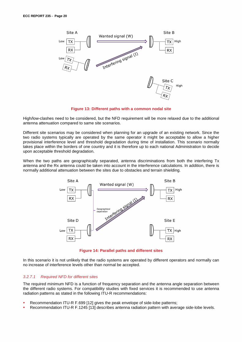
Given a situation when two different paths have one common site with an angular separation between the two paths, see Figure 13, additional antenna discrimination from one antenna can be taken into account in the interference calculations.
ECC REPORT 235 - Page 20
Figure 13: Different paths with a common nodal site
High/low-clashes need to be considered, but the NFD requirement will be more relaxed due to the additional antenna attenuation compared to same site scenarios.
Different site scenarios may be considered when planning for an upgrade of an existing network. Since the two radio systems typically are operated by the same operator it might be acceptable to allow a higher provisional interference level and threshold degradation during time of installation. This scenario normally takes place within the borders of one country and it is therefore up to each national Administration to decide upon acceptable threshold degradation.
When the two paths are geographically separated, antenna discriminations from both the interfering Tx antenna and the Rx antenna could be taken into account in the interference calculations. In addition, there is normally additional attenuation between the sites due to obstacles and terrain shielding.
Figure 14: Parallel paths and different sites
In this scenario it is not unlikely that the radio systems are operated by different operators and normally can no increase of interference levels other than normal be accepted.
3.2.7.1 Required NFD for different sites
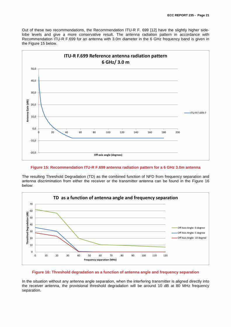
The required minimum NFD is a function of frequency separation and the antenna angle separation between the different radio systems. For compatibility studies with fixed services it is recommended to use antenna radiation patterns as stated in the following ITU-R recommendations:
Recommendation ITU-R F.699 [12] gives the peak envelope of side-lobe patterns; Recommendation ITU-R F.1245 [13] describes antenna radiation pattern with average side-lobe levels.
ECC REPORT 235 - Page 21
Out of these two recommendations, the Recommendation ITU-R F. 699 [12] have the slightly higher side-lobe levels and give a more conservative result. The antenna radiation pattern in accordance with Recommendation ITU-R F.699 for an antenna with 3.0m diameter in the 6 GHz frequency band is given in the Figure 15 below.
Figure 15: Recommendation ITU-R F.699 antenna radiation pattern for a 6 GHz 3.0m antenna
The resulting Threshold Degradation (TD) as the combined function of NFD from frequency separation and antenna discrimination from either the receiver or the transmitter antenna can be found in the Figure 16 below:
Figure 16: Threshold degradation as a function of antenna angle and frequency separation
In the situation without any antenna angle separation, when the interfering transmitter is aligned directly into the receiver antenna, the provisional threshold degradation will be around 10 dB at 80 MHz frequency separation.
-20,0
-10,0
0,0
10,0
20,0
30,0
40,0
50,0
0 20 40 60 80 100 120 140 160 180 200
Ante
nna
Gai
n (d
Bi)
Off-axis angle (degrees)
ITU-R F.699 Reference antenna radiation pattern6 GHz/ 3.0 m
ITU-R F.699-7
0
10
20
30
40
50
60
70
0 10 20 30 40 50 60 70 80 90 100 110 120
Thre
shho
d De
grad
atio
n (d
B)
Frequency separation (MHz)
TD as a function of antenna angle and frequency separation
Off Axis Angle- 0 degree
Off Axis Angle- 5 degree
Off Axis Angle- 10 degree
ECC REPORT 235 - Page 22
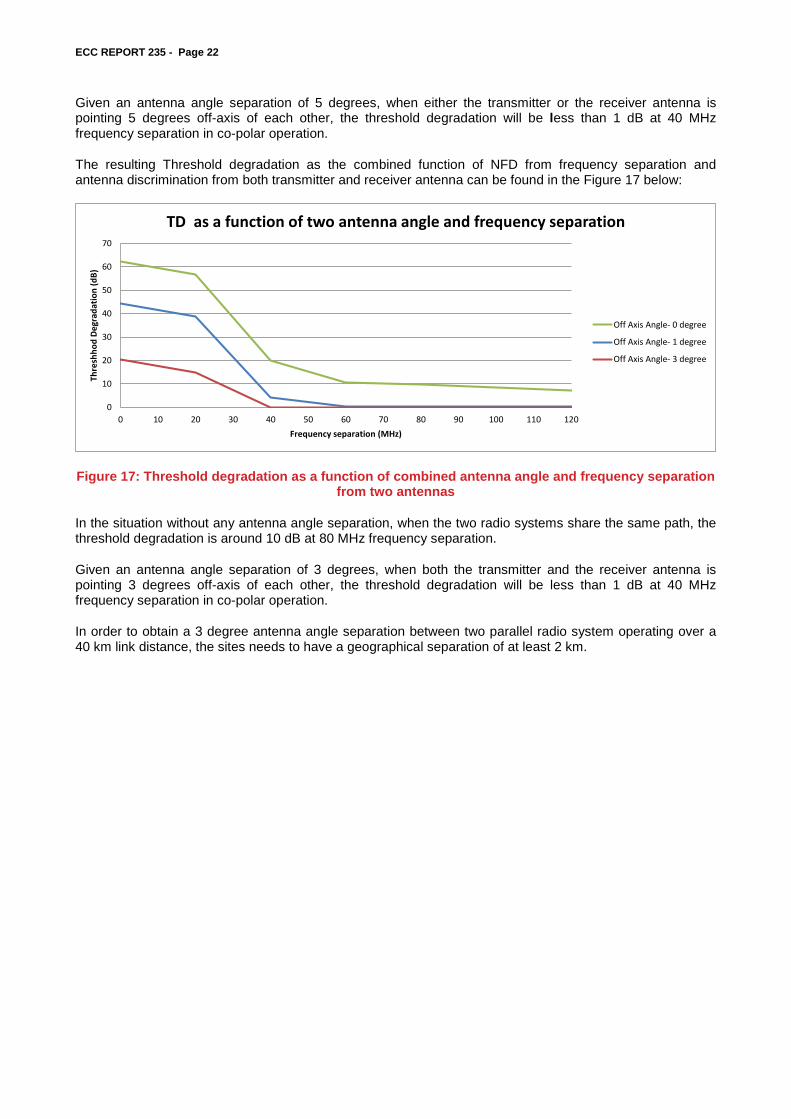
Given an antenna angle separation of 5 degrees, when either the transmitter or the receiver antenna is pointing 5 degrees off-axis of each other, the threshold degradation will be less than 1 dB at 40 MHz frequency separation in co-polar operation.
The resulting Threshold degradation as the combined function of NFD from frequency separation and antenna discrimination from both transmitter and receiver antenna can be found in the Figure 17 below:
Figure 17: Threshold degradation as a function of combined antenna angle and frequency separation from two antennas
In the situation without any antenna angle separation, when the two radio systems share the same path, the threshold degradation is around 10 dB at 80 MHz frequency separation.
Given an antenna angle separation of 3 degrees, when both the transmitter and the receiver antenna is pointing 3 degrees off-axis of each other, the threshold degradation will be less than 1 dB at 40 MHz frequency separation in co-polar operation.
In order to obtain a 3 degree antenna angle separation between two parallel radio system operating over a 40 km link distance, the sites needs to have a geographical separation of at least 2 km.
0
10
20
30
40
50
60
70
0 10 20 30 40 50 60 70 80 90 100 110 120
Thre
shho
d De
grad
atio
n (d
B)
Frequency separation (MHz)
TD as a function of two antenna angle and frequency separation
Off Axis Angle- 0 degree
Off Axis Angle- 1 degree
Off Axis Angle- 3 degree
ECC REPORT 235 - Page 23
4 RESTRUCTURING SCENARIOS
In areas where only one of the two frequency bands are available for Fixed Services in the foreseeable future it is recommended;
that the existing channel plan in each band is kept as is
or
that a new channel plan based upon 28/56 MHz channel separation is implemented in the available frequency band.
In areas where both the L6 GHz and U6 GHz bands are available for Fixed Services it is depending on the actual local situation on which restructuring scenario to use in accordance with the sections below.
Nevertheless, it is up to the individual administrations to implement any new channel plan.
The following sections describe the principles recommended to be used if/when considering changes from the L6 GHz and/or U6 GHz band.
4.1 HIGH/LOW SITE PRESERVATION
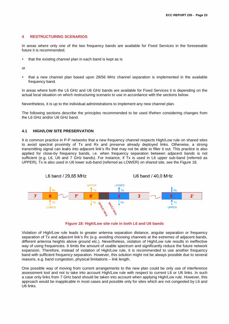
It is common practice in P-P networks that a new frequency channel respects High/Low rule on shared sites to avoid spectral proximity of Tx and Rx and preserve already deployed links. Otherwise, a strong transmitting signal can leaks into adjacent link’s Rx that may not be able to filter it out. This practice is also applied for close-by frequency bands, i.e. when frequency separation between adjacent bands is not sufficient (e.g. L6, U6 and 7 GHz bands). For instance, if Tx is used in L6 upper sub-band (referred as UPPER), Tx is also used in U6 lower sub-band (referred as LOWER) on shared site, see the Figure 18.
Figure 18: High/Low site rule in both L6 and U6 bands
Violation of High/Low rule leads to greater antenna separation distance, angular separation or frequency separation of Tx and adjacent link’s Rx (e.g. avoiding choosing channels at the extremes of adjacent bands, different antenna heights above ground etc.). Nevertheless, violation of High/Low rule results in ineffective way of using frequencies. It limits the amount of usable spectrum and significantly reduce the future network expansion. Therefore, instead of violation of High/Low rule, it is recommended to use another frequency band with sufficient frequency separation. However, this solution might not be always possible due to several reasons, e.g. band congestion, physical limitations – link length.
One possible way of moving from current arrangements to the new plan could be only use of interference assessment tool and not to take into account High/Low rule with respect to current L6 or U6 links. In such a case only links from 7 GHz band should be taken into account when applying High/Low rule. However, this approach would be inapplicable in most cases and possible only for sites which are not congested by L6 and U6 links.
ECC REPORT 235 - Page 24
The change of a current link can be understood as its cancelation and deployment of a new link. Cancelation represents release of Tx and Rx slots. Placing new Tx into spectral area which is used for Rx could block deployment of other new links or prevent restructuring of current L6 and U6 links, because placing of Tx next to Rx needs some frequency separation or another mitigation technique mentioned above. However, this necessary frequency separation may not be, especially for congested sites, available. Therefore it is recommended to use released spectrum as much as possible.
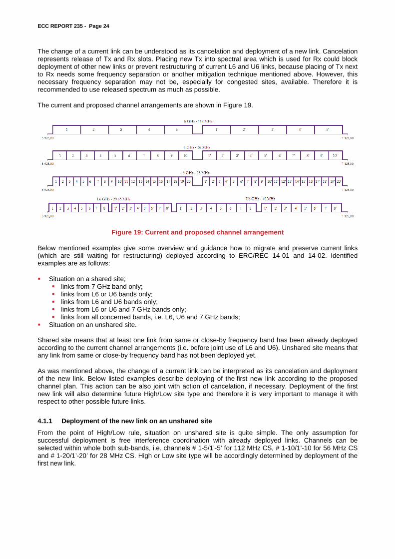
The current and proposed channel arrangements are shown in Figure 19.
Figure 19: Current and proposed channel arrangement
Below mentioned examples give some overview and guidance how to migrate and preserve current links (which are still waiting for restructuring) deployed according to ERC/REC 14-01 and 14-02. Identified examples are as follows:
Situation on a shared site; links from 7 GHz band only; links from L6 or U6 bands only; links from L6 and U6 bands only; links from L6 or U6 and 7 GHz bands only; links from all concerned bands, i.e. L6, U6 and 7 GHz bands;
Situation on an unshared site. Shared site means that at least one link from same or close-by frequency band has been already deployed according to the current channel arrangements (i.e. before joint use of L6 and U6). Unshared site means that any link from same or close-by frequency band has not been deployed yet.
As was mentioned above, the change of a current link can be interpreted as its cancelation and deployment of the new link. Below listed examples describe deploying of the first new link according to the proposed channel plan. This action can be also joint with action of cancelation, if necessary. Deployment of the first new link will also determine future High/Low site type and therefore it is very important to manage it with respect to other possible future links.
4.1.1 Deployment of the new link on an unshared site
From the point of High/Low rule, situation on unshared site is quite simple. The only assumption for successful deployment is free interference coordination with already deployed links. Channels can be selected within whole both sub-bands, i.e. channels # 1-5/1’-5’ for 112 MHz CS, # 1-10/1’-10 for 56 MHz CS and # 1-20/1’-20’ for 28 MHz CS. High or Low site type will be accordingly determined by deployment of the first new link.
ECC REPORT 235 - Page 25
4.1.2 Deployment of the new link on a shared site
The situation for a shared site is more complex. As was referred above, several examples can be identified.
4.1.2.1 Links from 7 GHz band only
To avoid spectral proximity of Tx/Rx from 6 GHz band and Rx/Tx 7 GHz band, it is necessary to choose Lower or Upper in 6 GHz band with respect to deployed links in 7 GHz band, i.e. Upper or Lower respectively. Violation of High/Low rule can lead to wasting spectrum or interference, especially for wider channels (56 MHz or 112 MHz), because strong transmitting signal can leak to adjacent link’s Rx and some guard bands would be necessary in such a case. Channels can be selected within whole upper or lower sub-band (i.e. channel # 1-5 or 1’-5’ for 112 MHz CS, # 1-10 or 1’-10 for 56 MHz CS and # 1-20 or 1’-20’ for 28 MHz CS) of the new channel plan. High or Low site type will be accordingly determined by deployment of the first new link.
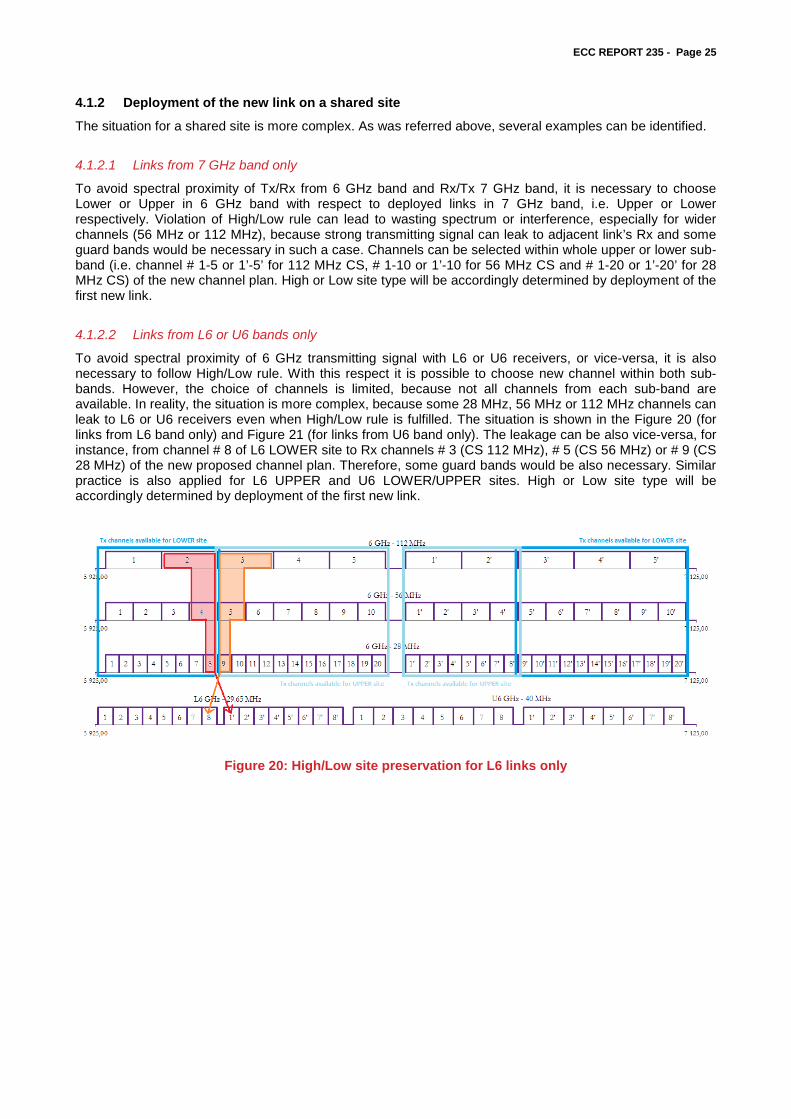
4.1.2.2 Links from L6 or U6 bands only
To avoid spectral proximity of 6 GHz transmitting signal with L6 or U6 receivers, or vice-versa, it is also necessary to follow High/Low rule. With this respect it is possible to choose new channel within both sub-bands. However, the choice of channels is limited, because not all channels from each sub-band are available. In reality, the situation is more complex, because some 28 MHz, 56 MHz or 112 MHz channels can leak to L6 or U6 receivers even when High/Low rule is fulfilled. The situation is shown in the Figure 20 (for links from L6 band only) and Figure 21 (for links from U6 band only). The leakage can be also vice-versa, for instance, from channel # 8 of L6 LOWER site to Rx channels # 3 (CS 112 MHz), # 5 (CS 56 MHz) or # 9 (CS 28 MHz) of the new proposed channel plan. Therefore, some guard bands would be also necessary. Similar practice is also applied for L6 UPPER and U6 LOWER/UPPER sites. High or Low site type will be accordingly determined by deployment of the first new link.
Figure 20: High/Low site preservation for L6 links only
ECC REPORT 235 - Page 26
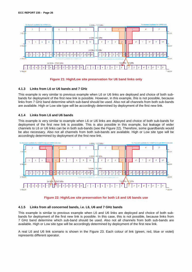
Figure 21: High/Low site preservation for U6 band links only
4.1.3 Links from L6 or U6 bands and 7 GHz
This example is very similar to previous example when L6 or U6 links are deployed and choice of both sub-bands for deployment of the first new link is possible. However, in this example, this is not possible, because links from 7 GHz band determine which sub-band should be used. Also not all channels from both sub-bands are available. High or Low site type will be accordingly determined by deployment of the first new link.
4.1.4 Links from L6 and U6 bands
This example is very similar to example when L6 or U6 links are deployed and choice of both sub-bands for deployment of the first new link is possible. This is also possible in this example, but leakage of wider channels to L6 or U6 links can be in both sub-bands (see the Figure 22). Therefore, some guardbands would be also necessary. Also not all channels from both sub-bands are available. High or Low site type will be accordingly determined by deployment of the first new link.
Figure 22: High/Low site preservation for both L6 and U6 bands use
4.1.5 Links from all concerned bands, i.e. L6, U6 and 7 GHz bands
This example is similar to previous example when L6 and U6 links are deployed and choice of both sub-bands for deployment of the first new link is possible. In this case, this is not possible, because links from 7 GHz band determine which sub-band should be used. Also not all channels from both sub-bands are available. High or Low site type will be accordingly determined by deployment of the first new link.
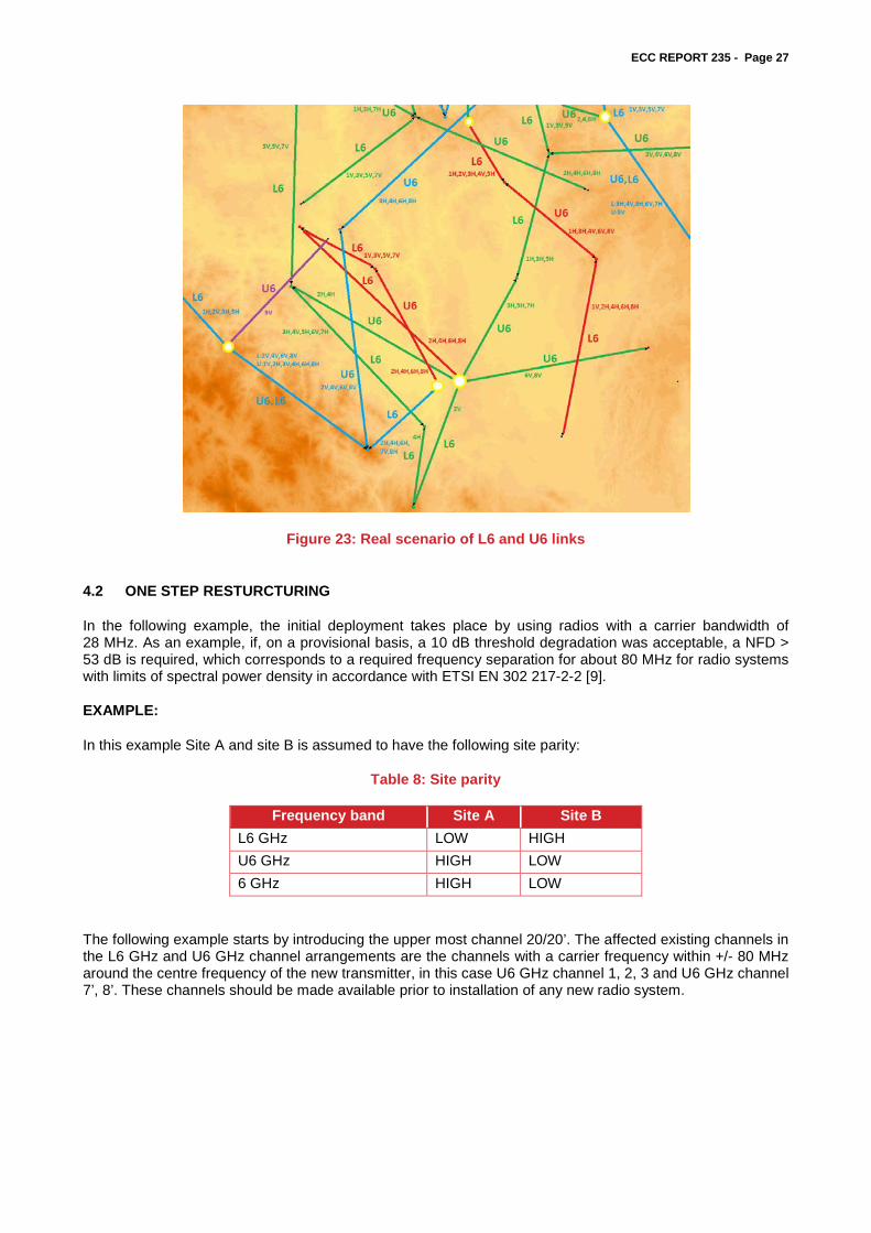
A real L6 and U6 link scenario is shown in the Figure 23. Each colour of link (green, red, blue or violet) represents different operator.
ECC REPORT 235 - Page 27
Figure 23: Real scenario of L6 and U6 links
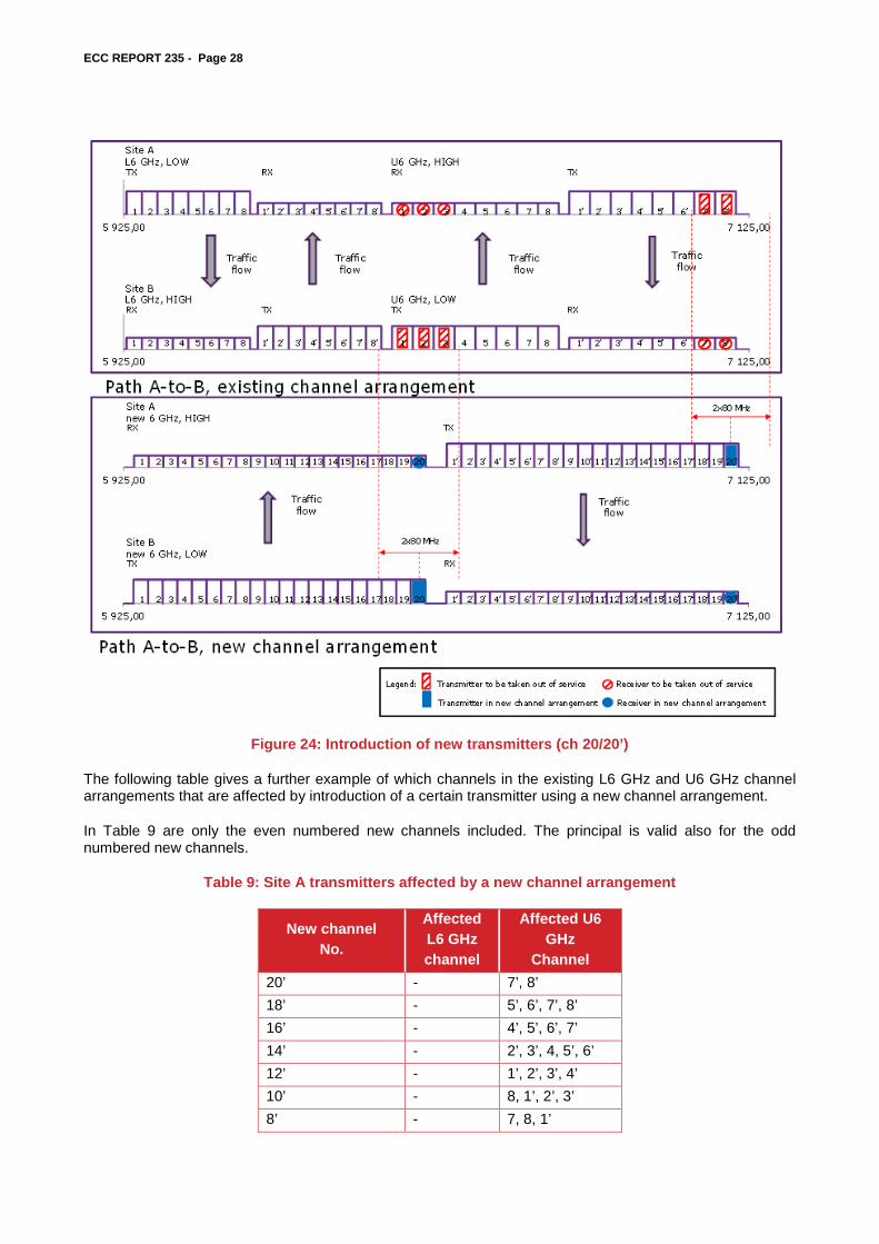
4.2 ONE STEP RESTURCTURING
In the following example, the initial deployment takes place by using radios with a carrier bandwidth of 28 MHz. As an example, if, on a provisional basis, a 10 dB threshold degradation was acceptable, a NFD > 53 dB is required, which corresponds to a required frequency separation for about 80 MHz for radio systems with limits of spectral power density in accordance with ETSI EN 302 217-2-2 [9].
EXAMPLE:
In this example Site A and site B is assumed to have the following site parity:
Table 8: Site parity
Frequency band Site A Site B L6 GHz LOW HIGH U6 GHz HIGH LOW 6 GHz HIGH LOW
The following example starts by introducing the upper most channel 20/20’. The affected existing channels in the L6 GHz and U6 GHz channel arrangements are the channels with a carrier frequency within +/- 80 MHz around the centre frequency of the new transmitter, in this case U6 GHz channel 1, 2, 3 and U6 GHz channel 7’, 8’. These channels should be made available prior to installation of any new radio system.
ECC REPORT 235 - Page 28
Figure 24: Introduction of new transmitters (ch 20/20’)
The following table gives a further example of which channels in the existing L6 GHz and U6 GHz channel arrangements that are affected by introduction of a certain transmitter using a new channel arrangement.
In Table 9 are only the even numbered new channels included. The principal is valid also for the odd numbered new channels.
Table 9: Site A transmitters affected by a new channel arrangement
New channel No.
Affected L6 GHz channel
Affected U6 GHz
Channel 20’ - 7’, 8’ 18’ - 5’, 6’, 7’, 8’ 16’ - 4’, 5’, 6’, 7’ 14’ - 2’, 3’, 4, 5’, 6’ 12’ - 1’, 2’, 3’, 4’ 10’ - 8, 1’, 2’, 3’ 8’ - 7, 8, 1’
ECC REPORT 235 - Page 29
New channel No.
Affected L6 GHz channel
Affected U6 GHz
Channel 6’ - 5, 6, 7, 8 4’ - 4, 5, 6, 7 2’ - 3, 4, 5, 6
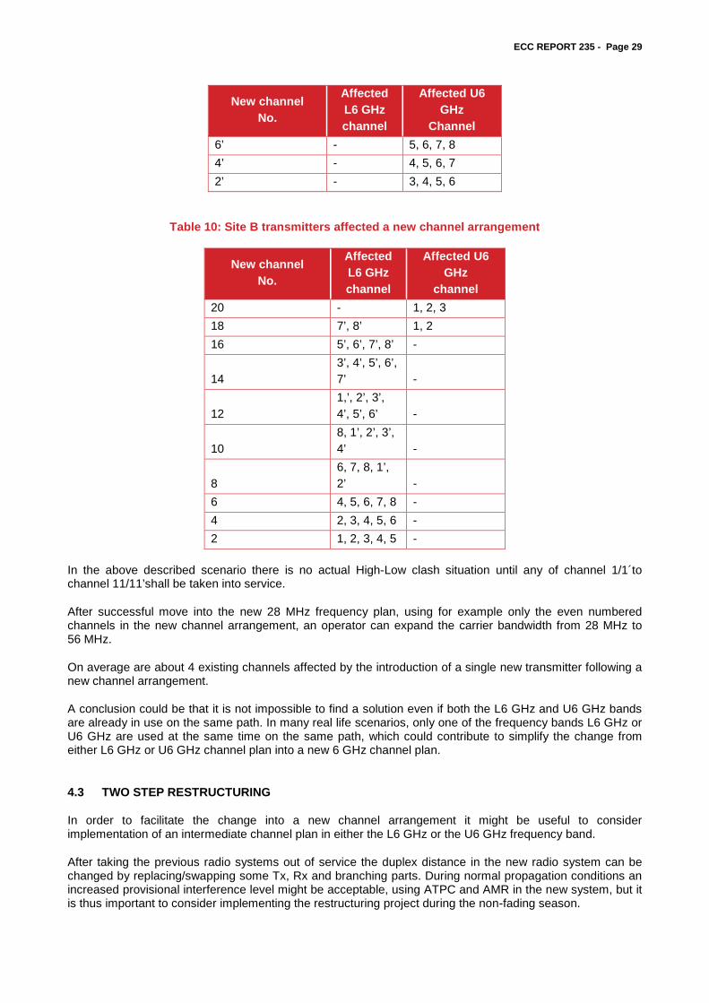
Table 10: Site B transmitters affected a new channel arrangement
New channel No.
Affected L6 GHz channel
Affected U6 GHz
channel 20 - 1, 2, 3 18 7’, 8’ 1, 2 16 5’, 6’, 7’, 8’ -
14 3’, 4’, 5’, 6’, 7’ -
12 1,’, 2’, 3’, 4’, 5’, 6’ -
10 8, 1’, 2’, 3’, 4’ -
8 6, 7, 8, 1’, 2’ -
6 4, 5, 6, 7, 8 - 4 2, 3, 4, 5, 6 - 2 1, 2, 3, 4, 5 -
In the above described scenario there is no actual High-Low clash situation until any of channel 1/1´to channel 11/11’shall be taken into service.
After successful move into the new 28 MHz frequency plan, using for example only the even numbered channels in the new channel arrangement, an operator can expand the carrier bandwidth from 28 MHz to 56 MHz.
On average are about 4 existing channels affected by the introduction of a single new transmitter following a new channel arrangement.
A conclusion could be that it is not impossible to find a solution even if both the L6 GHz and U6 GHz bands are already in use on the same path. In many real life scenarios, only one of the frequency bands L6 GHz or U6 GHz are used at the same time on the same path, which could contribute to simplify the change from either L6 GHz or U6 GHz channel plan into a new 6 GHz channel plan.
4.3 TWO STEP RESTRUCTURING
In order to facilitate the change into a new channel arrangement it might be useful to consider implementation of an intermediate channel plan in either the L6 GHz or the U6 GHz frequency band.
After taking the previous radio systems out of service the duplex distance in the new radio system can be changed by replacing/swapping some Tx, Rx and branching parts. During normal propagation conditions an increased provisional interference level might be acceptable, using ATPC and AMR in the new system, but it is thus important to consider implementing the restructuring project during the non-fading season.
ECC REPORT 235 - Page 30
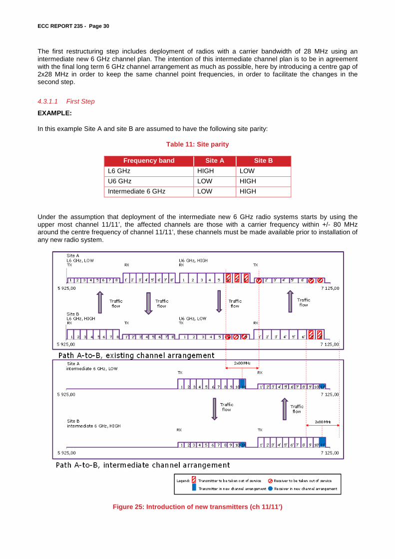
The first restructuring step includes deployment of radios with a carrier bandwidth of 28 MHz using an intermediate new 6 GHz channel plan. The intention of this intermediate channel plan is to be in agreement with the final long term 6 GHz channel arrangement as much as possible, here by introducing a centre gap of 2x28 MHz in order to keep the same channel point frequencies, in order to facilitate the changes in the second step.
4.3.1.1 First Step
EXAMPLE:
In this example Site A and site B are assumed to have the following site parity:
Table 11: Site parity
Frequency band Site A Site B L6 GHz HIGH LOW U6 GHz LOW HIGH Intermediate 6 GHz LOW HIGH
Under the assumption that deployment of the intermediate new 6 GHz radio systems starts by using the upper most channel 11/11’, the affected channels are those with a carrier frequency within +/- 80 MHz around the centre frequency of channel 11/11’, these channels must be made available prior to installation of any new radio system.
Figure 25: Introduction of new transmitters (ch 11/11’)
ECC REPORT 235 - Page 31
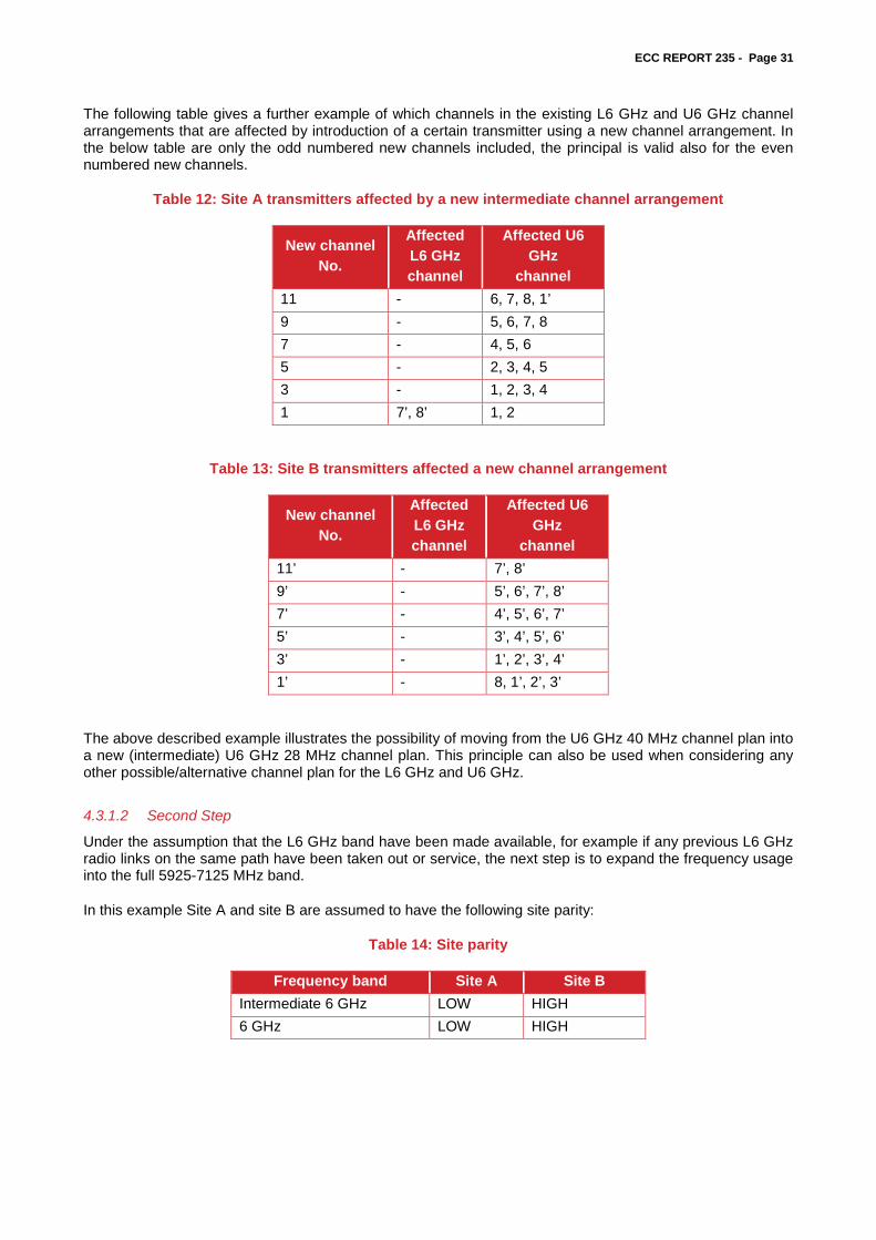
The following table gives a further example of which channels in the existing L6 GHz and U6 GHz channel arrangements that are affected by introduction of a certain transmitter using a new channel arrangement. In the below table are only the odd numbered new channels included, the principal is valid also for the even numbered new channels.
Table 12: Site A transmitters affected by a new intermediate channel arrangement
New channel No.
Affected L6 GHz channel
Affected U6 GHz
channel 11 - 6, 7, 8, 1’ 9 - 5, 6, 7, 8 7 - 4, 5, 6 5 - 2, 3, 4, 5 3 - 1, 2, 3, 4 1 7’, 8’ 1, 2
Table 13: Site B transmitters affected a new channel arrangement
New channel No.
Affected L6 GHz channel
Affected U6 GHz
channel 11’ - 7’, 8’ 9’ - 5’, 6’, 7’, 8’ 7’ - 4’, 5’, 6’, 7’ 5’ - 3’, 4’, 5’, 6’ 3’ - 1’, 2’, 3’, 4’ 1’ - 8, 1’, 2’, 3’
The above described example illustrates the possibility of moving from the U6 GHz 40 MHz channel plan into a new (intermediate) U6 GHz 28 MHz channel plan. This principle can also be used when considering any other possible/alternative channel plan for the L6 GHz and U6 GHz.
4.3.1.2 Second Step
Under the assumption that the L6 GHz band have been made available, for example if any previous L6 GHz radio links on the same path have been taken out or service, the next step is to expand the frequency usage into the full 5925-7125 MHz band.
In this example Site A and site B are assumed to have the following site parity:
Table 14: Site parity
Frequency band Site A Site B Intermediate 6 GHz LOW HIGH 6 GHz LOW HIGH
ECC REPORT 235 - Page 32
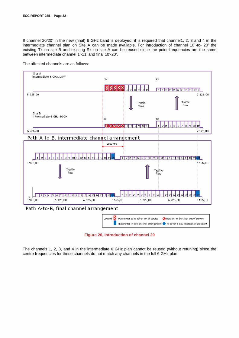
If channel 20/20’ in the new (final) 6 GHz band is deployed, it is required that channel1, 2, 3 and 4 in the intermediate channel plan on Site A can be made available. For introduction of channel 10´-to- 20’ the existing Tx on site B and existing Rx on site A can be reused since the point frequencies are the same between intermediate channel 1’-11’ and final 10’-20’.
The affected channels are as follows:
Figure 26, Introduction of channel 20
The channels 1, 2, 3, and 4 in the intermediate 6 GHz plan cannot be reused (without retuning) since the centre frequencies for these channels do not match any channels in the full 6 GHz plan.
ECC REPORT 235 - Page 33
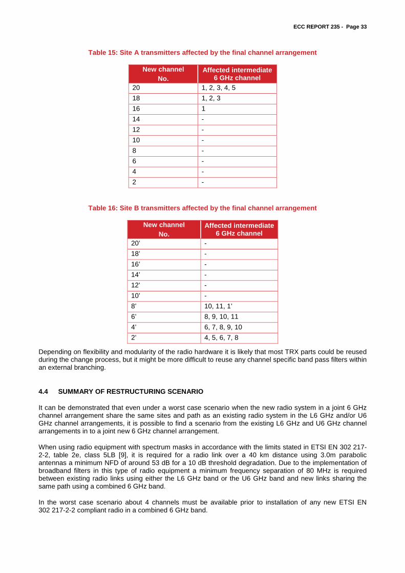
Table 15: Site A transmitters affected by the final channel arrangement
New channel No.
Affected intermediate 6 GHz channel
20 1, 2, 3, 4, 5 18 1, 2, 3 16 1 14 - 12 - 10 - 8 - 6 - 4 - 2 -
Table 16: Site B transmitters affected by the final channel arrangement
New channel No.
Affected intermediate 6 GHz channel
20’ - 18’ - 16’ - 14’ - 12’ - 10’ - 8’ 10, 11, 1’ 6’ 8, 9, 10, 11 4’ 6, 7, 8, 9, 10 2’ 4, 5, 6, 7, 8
Depending on flexibility and modularity of the radio hardware it is likely that most TRX parts could be reused during the change process, but it might be more difficult to reuse any channel specific band pass filters within an external branching.
4.4 SUMMARY OF RESTRUCTURING SCENARIO
It can be demonstrated that even under a worst case scenario when the new radio system in a joint 6 GHz channel arrangement share the same sites and path as an existing radio system in the L6 GHz and/or U6 GHz channel arrangements, it is possible to find a scenario from the existing L6 GHz and U6 GHz channel arrangements in to a joint new 6 GHz channel arrangement.
When using radio equipment with spectrum masks in accordance with the limits stated in ETSI EN 302 217-2-2, table 2e, class 5LB [9], it is required for a radio link over a 40 km distance using 3.0m parabolic antennas a minimum NFD of around 53 dB for a 10 dB threshold degradation. Due to the implementation of broadband filters in this type of radio equipment a minimum frequency separation of 80 MHz is required between existing radio links using either the L6 GHz band or the U6 GHz band and new links sharing the same path using a combined 6 GHz band.
In the worst case scenario about 4 channels must be available prior to installation of any new ETSI EN 302 217-2-2 compliant radio in a combined 6 GHz band.

ECC REPORT 235 - Page 34
5 CONCLUSION
High capacity long distance radio links could be suitable to deploy in areas where optical fibre is not a realistic solution from an economical perspective. The “fibre like” capacity needed can be supported by using a wide channel arrangement, with channel bandwidths up to 112 MHz, in a contiguous frequency band between 5925-7125 MHz. A wider contiguous frequency band can also result in a better business case for operators due to investment in fewer transceivers (transmitter/receiver pairs) and other cost savings related to fewer antennas and leasing of less space in towers.
The study also considers that all existing channels in the 5925-6425 MHz (ERC/REC 14-01 [1]) and 6425-7125 MHz (ERC/REC 14-02 [2]) frequency bands cannot co-exist with all new channels in a combined 5925-7125 MHz frequency band at the same time over a path between the same sites. Therefore a compromise during the time of installation and implementation will be required. It is common practice in P-P networks that a new frequency channel respects High/Low rule on shared sites for the same and adjacent frequency bands (e.g L6, U6 and 7 GHz). Violation of this rule limits the amount of usable spectrum and significantly reduces the future network expansion. Taking into account that several links of different operators can be deployed on a shared site, or both L6 and U6 bands are used simultaneously, it is possible that it will not be able for the transient period to preserve High/Low site consistency or to avoid spectral proximity of transmitting and receiving frequency of different links. This should be considered at national level on case by case basis.
ECC/REC/(14)06 [5] also provides option for implementation of Fixed Service Point-to-Point narrow channels in the guard bands and center gaps of the existing lower 6 GHz (5925 to 6425 MHz) and upper 6 GHz (6425 to 7125 MHz) bands for administration consideration.
Special attention has also been given to studies of different co-existence scenarios and to find a possible solution. The study highlights the difference in Tx emission limits stated in EN 302 217-2-2 and ETSI EN 302 217-2-1 [10]. Tx emission limits stated in EN 302 217-2-2, formally valid for CE assessment for all kind of equipment, are used in the main body of the Report in order to calculate Net Filter Discrimination (NFD) and finding a minimum required frequency separation between radio links using different channel arrangements. In ANNEX 2: the more stringent Tx limits stated in EN 302 217-2-1, typically valid only for indoor “multichannel trunk-like equipment”, are used, resulting in a lower required minimum frequency separation and an improved overall situation.
ECC REPORT 235 - Page 35
ANNEX 1: NFD BASED ON ETSI EN 302 217-2-2 TX EMISSION MASKS
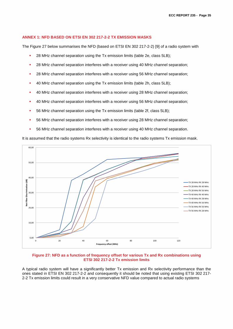
The Figure 27 below summarises the NFD (based on ETSI EN 302 217-2-2) [9] of a radio system with
28 MHz channel separation using the Tx emission limits (table 2e, class 5LB);
28 MHz channel separation interferes with a receiver using 40 MHz channel separation;
28 MHz channel separation interferes with a receiver using 56 MHz channel separation;
40 MHz channel separation using the Tx emission limits (table 2h, class 5LB);
40 MHz channel separation interferes with a receiver using 28 MHz channel separation;
40 MHz channel separation interferes with a receiver using 56 MHz channel separation;
56 MHz channel separation using the Tx emission limits (table 2f, class 5LB);
56 MHz channel separation interferes with a receiver using 28 MHz channel separation;
56 MHz channel separation interferes with a receiver using 40 MHz channel separation.
It is assumed that the radio systems Rx selectivity is identical to the radio systems Tx emission mask.
Figure 27: NFD as a function of frequency offset for various Tx and Rx combinations using ETSI 302 217-2-2 Tx emission limits
A typical radio system will have a significantly better Tx emission and Rx selectivity performance than the ones stated in ETSI EN 302 217-2-2 and consequently it should be noted that using existing ETSI 302 217-2-2 Tx emission limits could result in a very conservative NFD value compared to actual radio systems
0,00
10,00
20,00
30,00
40,00
50,00
60,00
0 20 40 60 80 100 120
Net
Filt
er D
iscr
imin
atio
n (d
B)
Frequency offset (MHz)
TX 28 MHz RX 28 MHz
TX 28 MHz RX 40 MHz
TX 28 MHz RX 56 MHz
TX 40 MHz RX 40 MHz
TX 40 MHz RX 28 MHz
TX 40 MHz RX 56 MHz
TX 56 MHz RX 56 MHz
TX 56 MHz RX 28 MHz
ECC REPORT 235 - Page 36
ANNEX 2: RESTRUCTURING SCENARIO USING ETSI EN 302 217-2-1 TX EMISSION MASK
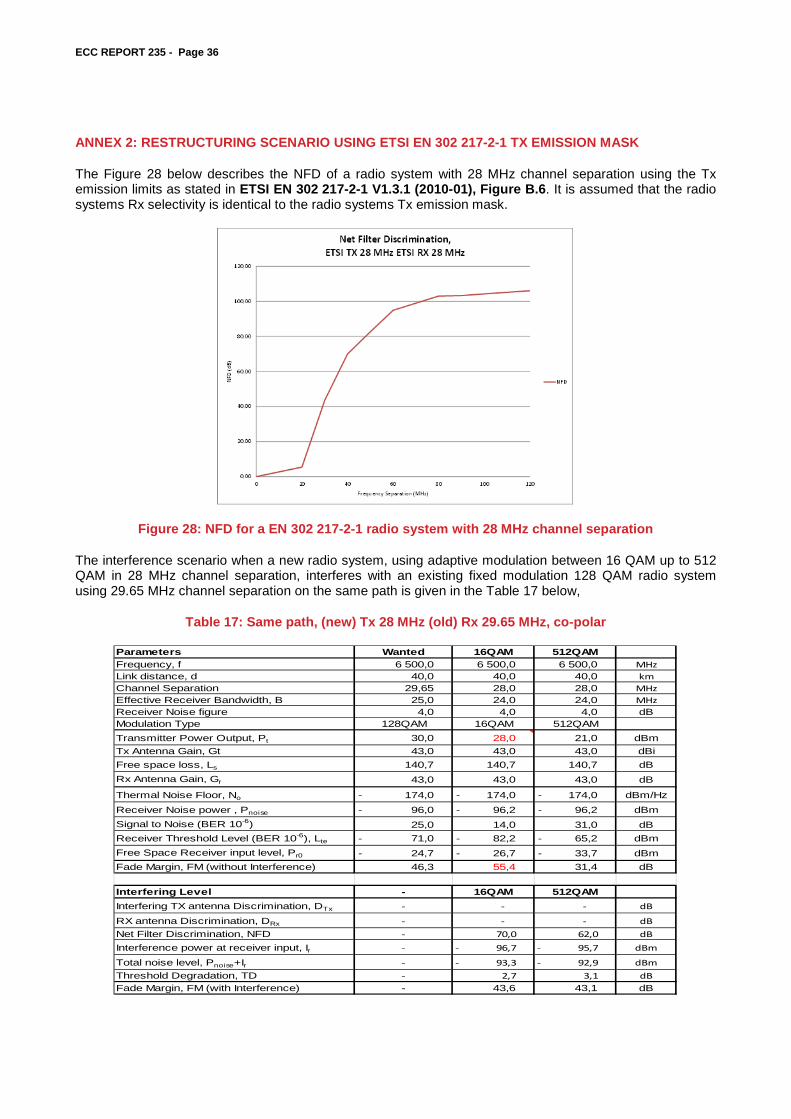
The Figure 28 below describes the NFD of a radio system with 28 MHz channel separation using the Tx emission limits as stated in ETSI EN 302 217-2-1 V1.3.1 (2010-01), Figure B.6. It is assumed that the radio systems Rx selectivity is identical to the radio systems Tx emission mask.
Figure 28: NFD for a EN 302 217-2-1 radio system with 28 MHz channel separation
The interference scenario when a new radio system, using adaptive modulation between 16 QAM up to 512 QAM in 28 MHz channel separation, interferes with an existing fixed modulation 128 QAM radio system using 29.65 MHz channel separation on the same path is given in the Table 17 below,
Table 17: Same path, (new) Tx 28 MHz (old) Rx 29.65 MHz, co-polar
Parameters Wanted 16QAM 512QAMFrequency, f 6 500,0 6 500,0 6 500,0 MHzLink distance, d 40,0 40,0 40,0 kmChannel Separation 29,65 28,0 28,0 MHzEffective Receiver Bandwidth, B 25,0 24,0 24,0 MHzReceiver Noise figure 4,0 4,0 4,0 dBModulation Type 128QAM 16QAM 512QAMTransmitter Power Output, Pt 30,0 28,0 21,0 dBmTx Antenna Gain, Gt 43,0 43,0 43,0 dBiFree space loss, Ls 140,7 140,7 140,7 dBRx Antenna Gain, Gr 43,0 43,0 43,0 dB
Thermal Noise Floor, No 174,0 - 174,0 - 174,0 - dBm/Hz
Receiver Noise power , Pnoise 96,0 - 96,2 - 96,2 - dBmSignal to Noise (BER 10-6) 25,0 14,0 31,0 dBReceiver Threshold Level (BER 10-6), Lte 71,0 - 82,2 - 65,2 - dBmFree Space Receiver input level, Pr0 24,7 - 26,7 - 33,7 - dBmFade Margin, FM (without Interference) 46,3 55,4 31,4 dB
Interfering Level - 16QAM 512QAMInterfering TX antenna Discrimination, DTx - - - dB
RX antenna Discrimination, DRx - - - dBNet Filter Discrimination, NFD - 70,0 62,0 dBInterference power at receiver input, Ir - 96,7 - 95,7 - dBm
Total noise level, Pnoise+Ir - 93,3 - 92,9 - dBmThreshold Degradation, TD - 2,7 3,1 dBFade Margin, FM (with Interference) - 43,6 43,1 dB

ECC REPORT 235 - Page 37
The calculated flat fade margin, without respect to any received interference, for the most robust modulation, 16 QAM, is considerably high (55.4 dB) and it could be considered to lower the maximum output power from +28dBm to for example +21 dBm (512 QAM reference) in order to minimize interference and setting the required NFD at co-polar operation to 70 dB irrespective of modulation format.
The existing system will experience a reduction of effective flat fade margin from 46.3 dB to 43.6 dB.
For the above described combination of radio systems, a NFD > 70 dB require a frequency separation of around 40 MHz for a 3 dB threshold degradation.
It could be noted that by using cross-polarisation and thus being able to account for a typical antenna XPD (see some reference) of around 30 dB, the threshold degradation will be negligible under the same conditions. For 3 dB threshold degradation under cross polar operation the requirements could be met if the frequency separation is > 30MHz.
A2.1 SUMMARY OF RESTRUCTURING SCENARIO
The scenario is the same as previously described in the main body of the report. The only difference is that the minimum required frequency separation is 40 MHz when using Tx emission limits in accordance with ETSI EN 302 217-2-1 [10] compared with the required 80 MHz frequency separation distance using Tx emission limits in accordance the ETSI EN 302 217-2-2 [9].
In the worst case scenario about 2 channels must be available prior to installation of any new ETSI EN 302 217-2-1 compliant radio in a combined 6 GHz band.
ECC REPORT 235 - Page 38
ANNEX 3: ANALYSIS ON NFD TO BE USED IN THE RESTRUCTURING STRATEGY
A3.1 FS SYSTEMS DESIGN AND ETSI STANDARDS
Since the entering into force of the 99/05/EC (R&TTE) Directive (year 2000), ETSI has decided to standardise, as “essential requirement” under Art. 3.2 of the Directive, only the “less stringent” RF spectrum mask achievable by current RF technology of equipment on the market.
At that time, and still today, but with different market sharing, two significantly different technologies were present:
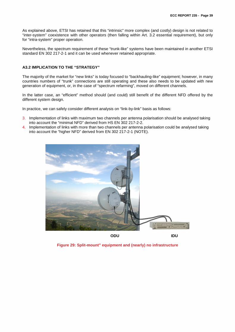
1. Backhauling-like” equipment, where the limited capacity needed for base stations connections and the operator’s need for fast and easy deployment and maintenance, requires a design for typical maximum two channels (typically adjacent) connected to the same (H or V) antenna port and a wide-band electronic tuning over the largest possible number of channels (so that the actual commissioning to the assigned frequency is made last minute in field).
This kind of equipment where initially placed on the market in bands above 15 GHz, but in late ‘90s, mobile operators, other than the old incumbent one, more and more requested longer hops connections in rural areas and for collecting traffic between larger cities; so avoiding fees and other bindings of using the “fixed core network”.
Also the need of avoiding large building infrastructure also required the design in “split-mount” configuration (IDU and ODU) or, more recently even “full-ODU” configuration.
Figure 29 shows typical example of such situation.
In these implementations, the Tx/Rx RF duplexer uses the widest band filters just permitting the compatibility of Tx with the corresponding Rx (i.e. innermost channel operation is not possible).
The Tx spectrum emission achievable by this kind of equipment has been used by ETSI as less stringent bases for defining the spectrum mask of equipment needed for fulfilling the “essential requirements” under Art. 3.2 of the R&TTE Directive (standardised in HS EN 302 217-2-2).
Therefore, the achievable NFD, for adjacent channels beyond the 1st (which is mostly linked to the digital shaping of the in-band spectrum), is not much increasing; practically, it is defined by the “unfiltered” spectrum emitted by the RF power amplifier with all its intermodulation products.
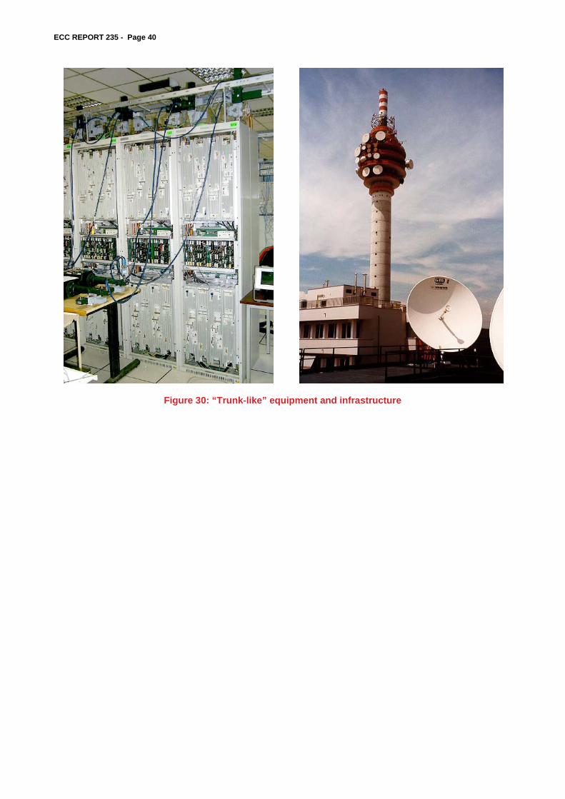
2. “Trunk-like”, multichannel full indoor systems, typically used by “previously incumbent” operators (of telecommunication and/or TV broadcasting) for long haul connections in the “fixed nation-wide core networks”. Deployment of such equipment implies the presence of building infrastructures (radio stations, with large air conditioned rooms connected to high antenna towers needed for long hop LoS conditions on relatively flat land).
In particular, this kind of equipment has been used only in bands up to 13 GHz (with few older examples in 15 and 18 GHz bands).
Figure 30 shows typical example of such situation in year 2000 technology.
In these implementations, the need for summing more than two channels to the same (H or V) antenna port automatically implies the use of narrow band branching filters for multi-channel Tx/Rx compatibility. This is also possible because of the far bigger HW size of the equipment.
This also implies that, while the co-channel and first adjacent channel NFD remain similar to that given by “backhauling-like” equipment, the 2nd and more adjacent NFD becomes, de facto higher, due to the more filtered emitted spectrum.
ECC REPORT 235 - Page 39
As explained above, ETSI has retained that this “intrinsic” more complex (and costly) design is not related to “inter-system” coexistence with other operators (then falling within Art. 3.2 essential requirement), but only for “intra-system” proper operation.
Nevertheless, the spectrum requirement of these “trunk-like” systems have been maintained in another ETSI standard EN 302 217-2-1 and it can be used whenever retained appropriate.
A3.2 IMPLICATION TO THE “STRATEGY”
The majority of the market for “new links” is today focused to “backhauling-like” equipment; however, in many countries numbers of “trunk” connections are still operating and these also needs to be updated with new generation of equipment, or, in the case of “spectrum refarming”, moved on different channels.
In the latter case, an “efficient” method should (and could) still benefit of the different NFD offered by the different system design.
In practice, we can safely consider different analysis on “link-by-link” basis as follows:
3. Implementation of links with maximum two channels per antenna polarisation should be analysed taking into account the “minimal NFD” derived from HS EN 302 217-2-2.
4. Implementation of links with more than two channels per antenna polarisation could be analysed taking into account the “higher NFD” derived from EN 302 217-2-1 (NOTE).
ODU IDU
Figure 29: Split-mount” equipment and (nearly) no infrastructure
ECC REPORT 235 - Page 40
Figure 30: “Trunk-like” equipment and infrastructure
ECC REPORT 235 - Page 41
ANNEX 4: CALCULATION OF REQUIRED NFD
A4.1 CO-LOCATED SITES
A4.1.1 Cross polarisation improvement
It could be noted that by using cross-polarisation and thus being able to account for a typical antenna XPD of 30 dB, the threshold degradation will be negligible under the same conditions. If, on a provisional basis, a 10 dB threshold degradation was acceptable, the requirements under cross-polarisation operation could be met if the frequency separation is > 30 MHz.
A4.1.2 Same path and co-located sites 3.0m parabolic antennas
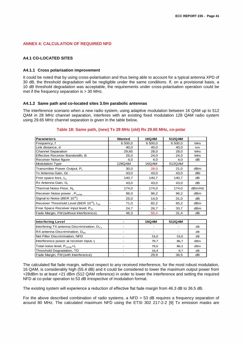
The interference scenario when a new radio system, using adaptive modulation between 16 QAM up to 512 QAM in 28 MHz channel separation, interferes with an existing fixed modulation 128 QAM radio system using 29.65 MHz channel separation is given in the table below,
Table 18: Same path, (new) Tx 28 MHz (old) Rx 29.65 MHz, co-polar
The calculated flat fade margin, without respect to any received interference, for the most robust modulation, 16 QAM, is considerably high (55.4 dB) and it could be considered to lower the maximum output power from +28dBm to at least +21 dBm (512 QAM reference) in order to lower the interference and setting the required NFD at co-polar operation to 53 dB irrespective of modulation format.
The existing system will experience a reduction of effective flat fade margin from 46.3 dB to 36.5 dB.
For the above described combination of radio systems, a NFD > 53 dB requires a frequency separation of around 80 MHz. The calculated maximum NFD using the ETSI 302 217-2-2 [9] Tx emission masks are
Parameters Wanted 16QAM 512QAMFrequency, f 6 500,0 6 500,0 6 500,0 MHzLink distance, d 40,0 40,0 40,0 kmChannel Separation 29,65 28,0 28,0 MHzEffective Receiver Bandwidth, B 25,0 24,0 24,0 MHzReceiver Noise figure 4,0 4,0 4,0 dBModulation Type 128QAM 16QAM 512QAMTransmitter Power Output, Pt 30,0 28,0 21,0 dBmTx Antenna Gain, Gt 43,0 43,0 43,0 dBiFree space loss, Ls 140,7 140,7 140,7 dBRx Antenna Gain, Gr 43,0 43,0 43,0 dB
Thermal Noise Floor, No 174,0 - 174,0 - 174,0 - dBm/Hz
Receiver Noise power , Pnoise 96,0 - 96,2 - 96,2 - dBmSignal to Noise (BER 10-6) 25,0 14,0 31,0 dBReceiver Threshold Level (BER 10-6), Lte 71,0 - 82,2 - 65,2 - dBmFree Space Receiver input level, Pr0 24,7 - 26,7 - 33,7 - dBmFade Margin, FM (without Interference) 46,3 55,4 31,4 dB
Interfering Level - 16QAM 512QAMInterfering TX antenna Discrimination, DTx - - - dB
RX antenna Discrimination, DRx - - - dBNet Filter Discrimination, NFD - 53,0 53,0 dBInterference power at receiver input, Ir - 79,7 - 86,7 - dBm
Total noise level, Pnoise+Ir - 79,6 - 86,3 - dBmThreshold Degradation, TD - 16,4 9,7 dBFade Margin, FM (with Interference) - 29,9 36,5 dB

ECC REPORT 235 - Page 42
around 54 dB and given the high receiver input level, and a resulting excessive fading margin, some provisional threshold degradation needs to be accepted when operating radio links sharing the same path.
The interference scenario when the existing fixed modulation radio system interferes with the new radio system is given in the table below.
Table 19: Same path, (old) Tx 29.65 MHz (new) Rx 28 MHz, co-polar
In this example, the existing radio system have a higher transmit power which will result in that the new radio system will experience a higher interference level than what was the case in the opposite direction.
The existing system will experience a reduction of effective flat fade margin from 48.4 dB to 29.9 dB for the most robust modulation format under co polar operation.
The interference scenario when a new radio system, using adaptive modulation between 16 QAM up to 512 QAM in 28 MHz channel separation, interferes with an existing fixed modulation 64 QAM radio system using 40 MHz channel separation is given in the Table 20 below,
Parameters 16QAM Site A-BFrequency, f 6 500,0 6 500,0 MHzLink distance, d 40,0 40,0 kmChannel Separation 28,00 28,0 MHzEffective Receiver Bandwidth, B 24,0 24,0 MHzReceiver Noise figure 4,0 4,0 dBModulation Type 16QAM 128QAMTransmitter Power Output, Pt 21,0 30,0 dBmTx Antenna Gain, Gt 43,0 43,0 dBiFree space loss, Ls 140,7 140,7 dBRx Antenna Gain, Gr 43,0 43,0 dB
Thermal Noise Floor, No 174,0 - 174,0 - dBm/Hz
Receiver Noise power , Pnoise 96,2 - 96,2 - dBmSignal to Noise (BER 10-6) 14,0 25,0 dBReceiver Threshold Level (BER 10-6), Lte 82,2 - 71,2 - dBmFree Space Receiver input level, Pr0 33,7 - 24,7 - dBmFade Margin, FM (without Interference) 48,4 46,4 dB
Interfering Level - Site A-BInterfering TX antenna Discrimination, DTx - - dB
RX antenna Discrimination, DRx - - dBNet Filter Discrimination, NFD - 53,0 dBInterference power at receiver input, Ir - 77,7 - dBm
Total noise level, Pnoise+Ir - 77,7 - dBmThreshold Degradation, TD - 18,5 dBFade Margin, FM (with Interference) - 29,9 dB

ECC REPORT 235 - Page 43
Table 20: Same path, (new) Tx 28 MHz (old) Rx 40 MHz, co-polar
The calculated flat fade margin, without respect to any received interference, for the most robust modulation, 16 QAM, is considerably high (55.4 dB) and it could be considered to lower the maximum output power from +28 dBm to for example +21 dBm (512 QAM reference) in order to minimize interference and setting the required NFD at co-polar operation to 52 dB irrespective of modulation format.
The existing system will experience a reduction of effective flat fade margin from 48.5 dB to 38.5 dB.
With reference to Figure 10, for the above described combination of radio systems, a NFD > 52 dB requires a frequency separation of around 80 MHz.
The interference scenario when the existing fixed modulation radio system interferes with the new radio system is given in the Table 21 below.
Parameters Wanted 16QAM 512QAMFrequency, f 6 500,0 6 500,0 6 500,0 MHzLink distance, d 40,0 40,0 40,0 kmChannel Separation 40,00 28,0 28,0 MHzEffective Receiver Bandwidth, B 30,0 24,0 24,0 MHzReceiver Noise figure 4,0 4,0 4,0 dBModulation Type 64QAM 16QAM 512QAMTransmitter Power Output, Pt 30,0 28,0 21,0 dBmTx Antenna Gain, Gt 43,0 43,0 43,0 dBiFree space loss, Ls 140,7 140,7 140,7 dBRx Antenna Gain, Gr 43,0 43,0 43,0 dB
Thermal Noise Floor, No 174,0 - 174,0 - 174,0 - dBm/Hz
Receiver Noise power , Pnoise 95,2 - 96,2 - 96,2 - dBmSignal to Noise (BER 10-6) 22,0 14,0 31,0 dBReceiver Threshold Level (BER 10-6), Lte 73,2 - 82,2 - 65,2 - dBmFree Space Receiver input level, Pr0 24,7 - 26,7 - 33,7 - dBmFade Margin, FM (without Interference) 48,5 55,4 31,4 dB
Interfering Level - 16QAM 512QAMInterfering TX antenna Discrimination, DTx - - - dB
RX antenna Discrimination, DRx - - - dBNet Filter Discrimination, NFD - 52,0 52,0 dBInterference power at receiver input, Ir - 78,7 - 85,7 - dBm
Total noise level, Pnoise+Ir - 78,6 - 85,3 - dBmThreshold Degradation, TD - 16,6 9,9 dBFade Margin, FM (with Interference) - 31,9 38,5 dB
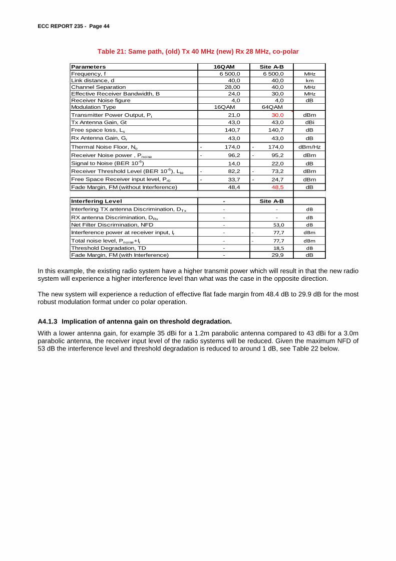
ECC REPORT 235 - Page 44
Table 21: Same path, (old) Tx 40 MHz (new) Rx 28 MHz, co-polar
In this example, the existing radio system have a higher transmit power which will result in that the new radio system will experience a higher interference level than what was the case in the opposite direction.
The new system will experience a reduction of effective flat fade margin from 48.4 dB to 29.9 dB for the most robust modulation format under co polar operation.
A4.1.3 Implication of antenna gain on threshold degradation.
With a lower antenna gain, for example 35 dBi for a 1.2m parabolic antenna compared to 43 dBi for a 3.0m parabolic antenna, the receiver input level of the radio systems will be reduced. Given the maximum NFD of 53 dB the interference level and threshold degradation is reduced to around 1 dB, see Table 22 below.
Parameters 16QAM Site A-BFrequency, f 6 500,0 6 500,0 MHzLink distance, d 40,0 40,0 kmChannel Separation 28,00 40,0 MHzEffective Receiver Bandwidth, B 24,0 30,0 MHzReceiver Noise figure 4,0 4,0 dBModulation Type 16QAM 64QAMTransmitter Power Output, Pt 21,0 30,0 dBmTx Antenna Gain, Gt 43,0 43,0 dBiFree space loss, Ls 140,7 140,7 dBRx Antenna Gain, Gr 43,0 43,0 dB
Thermal Noise Floor, No 174,0 - 174,0 - dBm/Hz
Receiver Noise power , Pnoise 96,2 - 95,2 - dBmSignal to Noise (BER 10-6) 14,0 22,0 dBReceiver Threshold Level (BER 10-6), Lte 82,2 - 73,2 - dBmFree Space Receiver input level, Pr0 33,7 - 24,7 - dBmFade Margin, FM (without Interference) 48,4 48,5 dB
Interfering Level - Site A-BInterfering TX antenna Discrimination, DTx - - dB
RX antenna Discrimination, DRx - - dBNet Filter Discrimination, NFD - 53,0 dBInterference power at receiver input, Ir - 77,7 - dBm
Total noise level, Pnoise+Ir - 77,7 - dBmThreshold Degradation, TD - 18,5 dBFade Margin, FM (with Interference) - 29,9 dB

ECC REPORT 235 - Page 45
Table 22: Same path, (new) Tx 28 MHz (old) Rx 29.65 MHz, co-polar, 1.2m antenna
A4.1.4 Same path and co-located sites with different site parity
The various parameters and calculation result, when the two radio systems share the same path and sites under co-polar conditions, and when there is a site parity conflict (High-Low clash), are given for a provisional 10 dB threshold degradation in the Table 23 below. The two radio systems antennas are located in the same tower and are assumed to have a vertical separation of 5m.
Parameters Wanted 16QAM 512QAMFrequency, f 6 500,0 6 500,0 6 500,0 MHzLink distance, d 40,0 40,0 40,0 kmChannel Separation 29,65 28,0 28,0 MHzEffective Receiver Bandwidth, B 25,0 24,0 24,0 MHzReceiver Noise figure 4,0 4,0 4,0 dBModulation Type 128QAM 16QAM 512QAMTransmitter Power Output, Pt 30,0 28,0 21,0 dBmTx Antenna Gain, Gt 35,0 35,0 35,0 dBiFree space loss, Ls 140,7 140,7 140,7 dBRx Antenna Gain, Gr 35,0 35,0 35,0 dB
Thermal Noise Floor, No 174,0 - 174,0 - 174,0 - dBm/Hz
Receiver Noise power , Pnoise 96,0 - 96,2 - 96,2 - dBmSignal to Noise (BER 10-6) 25,0 14,0 31,0 dBReceiver Threshold Level (BER 10-6), Lte 71,0 - 82,2 - 65,2 - dBmFree Space Receiver input level, Pr0 40,7 - 42,7 - 49,7 - dBmFade Margin, FM (without Interference) 30,3 39,4 15,4 dB
Interfering Level - 16QAM 512QAMInterfering TX antenna Discrimination, DTx - - - dB
RX antenna Discrimination, DRx - - - dBNet Filter Discrimination, NFD - 53,0 53,0 dBInterference power at receiver input, Ir - 95,7 - 102,7 - dBm
Total noise level, Pnoise+Ir - 92,9 - 95,2 - dBmThreshold Degradation, TD - 3,1 0,8 dBFade Margin, FM (with Interference) - 27,1 29,4 dB
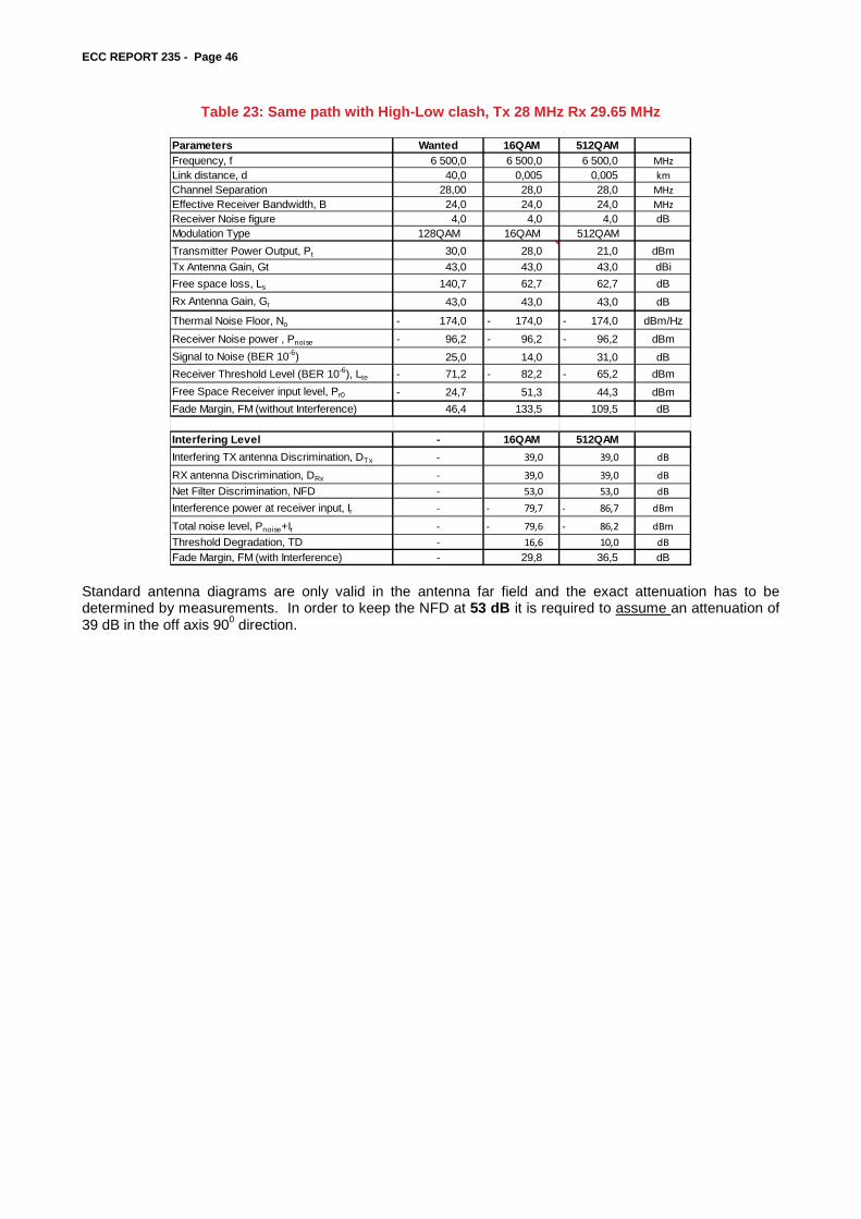
ECC REPORT 235 - Page 46
Table 23: Same path with High-Low clash, Tx 28 MHz Rx 29.65 MHz
Standard antenna diagrams are only valid in the antenna far field and the exact attenuation has to be determined by measurements. In order to keep the NFD at 53 dB it is required to assume an attenuation of 39 dB in the off axis 900 direction.
Parameters Wanted 16QAM 512QAMFrequency, f 6 500,0 6 500,0 6 500,0 MHzLink distance, d 40,0 0,005 0,005 kmChannel Separation 28,00 28,0 28,0 MHzEffective Receiver Bandwidth, B 24,0 24,0 24,0 MHzReceiver Noise figure 4,0 4,0 4,0 dBModulation Type 128QAM 16QAM 512QAMTransmitter Power Output, Pt 30,0 28,0 21,0 dBmTx Antenna Gain, Gt 43,0 43,0 43,0 dBiFree space loss, Ls 140,7 62,7 62,7 dBRx Antenna Gain, Gr 43,0 43,0 43,0 dB
Thermal Noise Floor, No 174,0 - 174,0 - 174,0 - dBm/Hz
Receiver Noise power , Pnoise 96,2 - 96,2 - 96,2 - dBmSignal to Noise (BER 10-6) 25,0 14,0 31,0 dBReceiver Threshold Level (BER 10-6), Lte 71,2 - 82,2 - 65,2 - dBmFree Space Receiver input level, Pr0 24,7 - 51,3 44,3 dBmFade Margin, FM (without Interference) 46,4 133,5 109,5 dB
Interfering Level - 16QAM 512QAMInterfering TX antenna Discrimination, DTx - 39,0 39,0 dB
RX antenna Discrimination, DRx - 39,0 39,0 dBNet Filter Discrimination, NFD - 53,0 53,0 dBInterference power at receiver input, Ir - 79,7 - 86,7 - dBm
Total noise level, Pnoise+Ir - 79,6 - 86,2 - dBmThreshold Degradation, TD - 16,6 10,0 dBFade Margin, FM (with Interference) - 29,8 36,5 dB
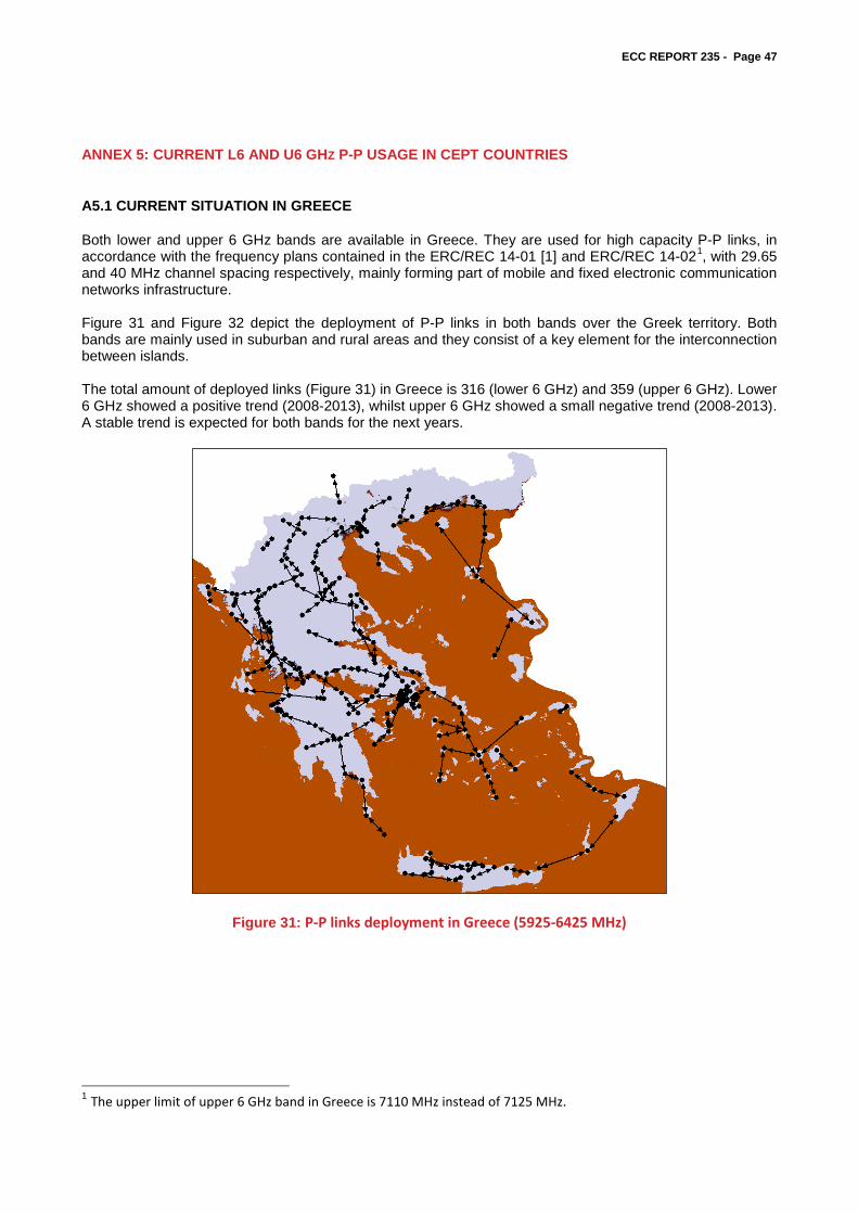
ECC REPORT 235 - Page 47
ANNEX 5: CURRENT L6 AND U6 GHZ P-P USAGE IN CEPT COUNTRIES
A5.1 CURRENT SITUATION IN GREECE
Both lower and upper 6 GHz bands are available in Greece. They are used for high capacity P-P links, in accordance with the frequency plans contained in the ERC/REC 14-01 [1] and ERC/REC 14-021, with 29.65 and 40 MHz channel spacing respectively, mainly forming part of mobile and fixed electronic communication networks infrastructure. Figure 31 and Figure 32 depict the deployment of P-P links in both bands over the Greek territory. Both bands are mainly used in suburban and rural areas and they consist of a key element for the interconnection between islands. The total amount of deployed links (Figure 31) in Greece is 316 (lower 6 GHz) and 359 (upper 6 GHz). Lower 6 GHz showed a positive trend (2008-2013), whilst upper 6 GHz showed a small negative trend (2008-2013). A stable trend is expected for both bands for the next years.
Figure 31: P-P links deployment in Greece (5925-6425 MHz)
1 The upper limit of upper 6 GHz band in Greece is 7110 MHz instead of 7125 MHz.
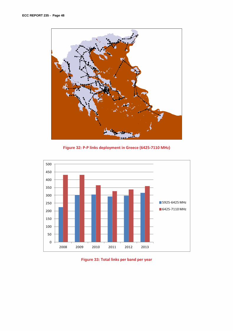
ECC REPORT 235 - Page 48
Figure 32: P-P links deployment in Greece (6425-7110 MHz)
Figure 33: Total links per band per year
0
50
100
150
200
250
300
350
400
450
500
2008 2009 2010 2011 2012 2013
5925-6425 MHz
6425-7110 MHz
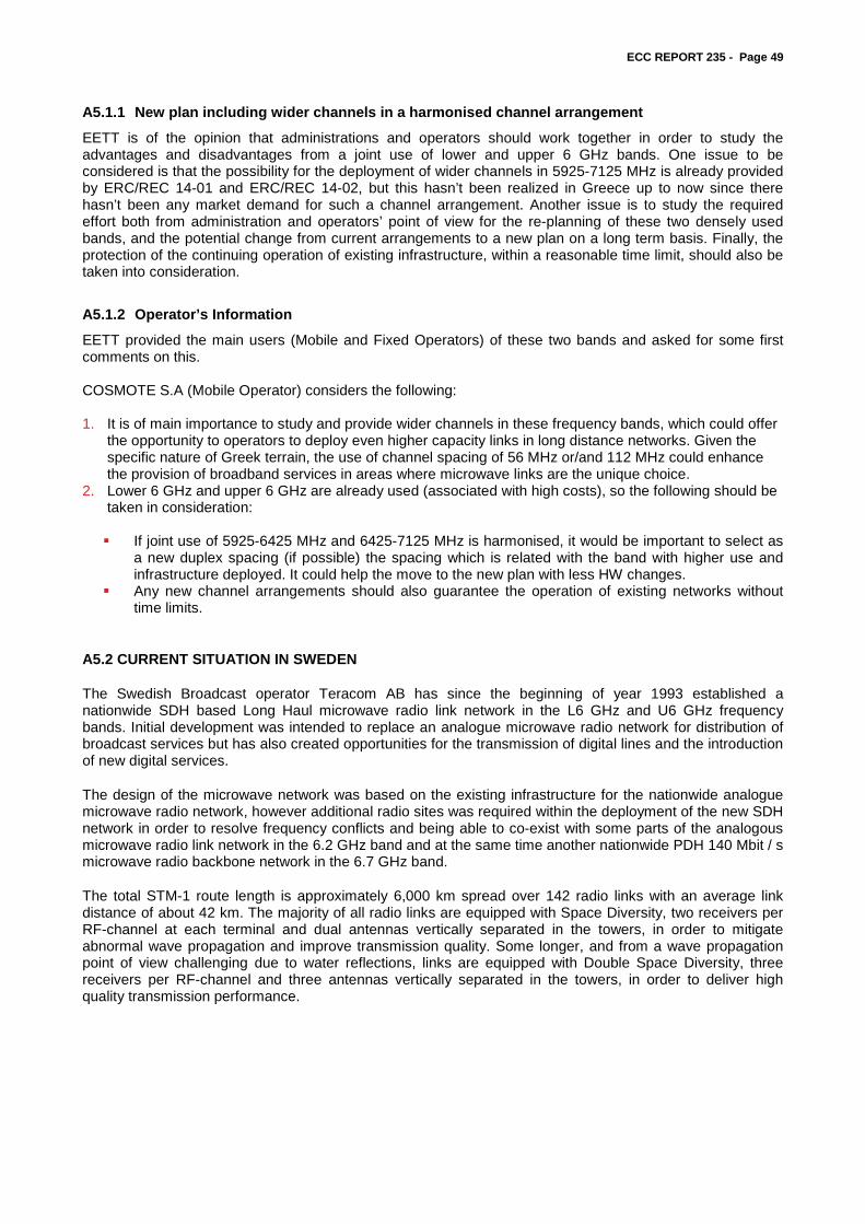
ECC REPORT 235 - Page 49
A5.1.1 New plan including wider channels in a harmonised channel arrangement
EETT is of the opinion that administrations and operators should work together in order to study the advantages and disadvantages from a joint use of lower and upper 6 GHz bands. One issue to be considered is that the possibility for the deployment of wider channels in 5925-7125 MHz is already provided by ERC/REC 14-01 and ERC/REC 14-02, but this hasn’t been realized in Greece up to now since there hasn’t been any market demand for such a channel arrangement. Another issue is to study the required effort both from administration and operators’ point of view for the re-planning of these two densely used bands, and the potential change from current arrangements to a new plan on a long term basis. Finally, the protection of the continuing operation of existing infrastructure, within a reasonable time limit, should also be taken into consideration.
A5.1.2 Operator’s Information
EETT provided the main users (Mobile and Fixed Operators) of these two bands and asked for some first comments on this. COSMOTE S.A (Mobile Operator) considers the following: 1. It is of main importance to study and provide wider channels in these frequency bands, which could offer
the opportunity to operators to deploy even higher capacity links in long distance networks. Given the specific nature of Greek terrain, the use of channel spacing of 56 MHz or/and 112 MHz could enhance the provision of broadband services in areas where microwave links are the unique choice.
2. Lower 6 GHz and upper 6 GHz are already used (associated with high costs), so the following should be taken in consideration:
If joint use of 5925-6425 MHz and 6425-7125 MHz is harmonised, it would be important to select as
a new duplex spacing (if possible) the spacing which is related with the band with higher use and infrastructure deployed. It could help the move to the new plan with less HW changes.
Any new channel arrangements should also guarantee the operation of existing networks without time limits.
A5.2 CURRENT SITUATION IN SWEDEN
The Swedish Broadcast operator Teracom AB has since the beginning of year 1993 established a nationwide SDH based Long Haul microwave radio link network in the L6 GHz and U6 GHz frequency bands. Initial development was intended to replace an analogue microwave radio network for distribution of broadcast services but has also created opportunities for the transmission of digital lines and the introduction of new digital services.
The design of the microwave network was based on the existing infrastructure for the nationwide analogue microwave radio network, however additional radio sites was required within the deployment of the new SDH network in order to resolve frequency conflicts and being able to co-exist with some parts of the analogous microwave radio link network in the 6.2 GHz band and at the same time another nationwide PDH 140 Mbit / s microwave radio backbone network in the 6.7 GHz band.
The total STM-1 route length is approximately 6,000 km spread over 142 radio links with an average link distance of about 42 km. The majority of all radio links are equipped with Space Diversity, two receivers per RF-channel at each terminal and dual antennas vertically separated in the towers, in order to mitigate abnormal wave propagation and improve transmission quality. Some longer, and from a wave propagation point of view challenging due to water reflections, links are equipped with Double Space Diversity, three receivers per RF-channel and three antennas vertically separated in the towers, in order to deliver high quality transmission performance.

ECC REPORT 235 - Page 50
The configuration of the radio links in the L6 GHz and U6 GHz in Sweden are stated in the Table 24 below:
Table 24: Number of radio links in the L6 GHz and U6 GHz bands
Configuration No. of
6.2 GHz links No. of
6.7 GHz links 1+0 8 2 1+1 9 6 2+1 3 10 3+1 2 5 4+1 5 1 5+1 18 18 6+1 18 19 7+1 20 14
All links in the 6.2 GHz and 6.7 GHz bands are using the Adjacent Channel Dual Polarisation (ACDP) mode, Co Channel Dual Polarisation (CCDP) mode is not used.
Besides the 142 links in the 6.2 GHz and 6.7 GHz bands operated by Teracom AB, there is 16 more links in the 6.2 GHz band operated by one (1) other operator.
A5.3 PREDICTED PERFOMANCE
The Figure 34 below show the average predicted availability with respect to wave propagation (by using Recommendation ITU-R P.530-10 [16]), but not including hardware failure, for the about 130 of the links comprising the previous Swedish Long Haul radio network in the L6 GHz and U6 GHz frequency bands.
The average predicted availability for the previous installed STM-1 radios using fixed modulation are 99.9970% per link.
Figure 34: Prediction Availability 64 QAM/40 MHz vs. AMR 40 MHz and AMR 56 MHz
99,9860%
99,9880%
99,9900%
99,9920%
99,9940%
99,9960%
99,9980%
100,0000%
0 50 100 150 200 250 300 350 400 450
Avai
labi
lity
Capacity (Mbps)
Fixed Modulation STM-1 radio vs Adaptiv Modulation radio with 40/56 MHz CS
STM-1
IP AMR-40MHz
IP AMR-56 MHz
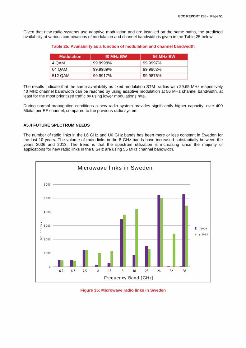
ECC REPORT 235 - Page 51
Given that new radio systems use adaptive modulation and are installed on the same paths, the predicted availability at various combinations of modulation and channel bandwidth is given in the Table 25 below:
Table 25: Availability as a function of modulation and channel bandwidth
Modulation 40 MHz BW 56 MHz BW 4 QAM 99.9998% 99.9997% 64 QAM 99.9989% 99.9982% 512 QAM 99.9917% 99.9875%
The results indicate that the same availability as fixed modulation STM- radios with 29.65 MHz respectively 40 MHz channel bandwidth can be reached by using adaptive modulation at 56 MHz channel bandwidth, at least for the most prioritized traffic by using lower modulations rate.
During normal propagation conditions a new radio system provides significantly higher capacity, over 400 Mbit/s per RF channel, compared to the previous radio system.
A5.4 FUTURE SPECTRUM NEEDS
The number of radio links in the L6 GHz and U6 GHz bands has been more or less constant in Sweden for the last 10 years. The volume of radio links in the 8 GHz bands have increased substantially between the years 2006 and 2013. The trend is that the spectrum utilization is increasing since the majority of applications for new radio links in the 8 GHz are using 56 MHz channel bandwidth.
Figure 35: Microwave radio links in Sweden
0
1 000
2 000
3 000
4 000
5 000
6 000
1 2 3 4 5 6 7 8 9 10 11
An
tal
Ra
dio
län
k
Frekvensband [GHz]
Antal Radiolänk 6-38 GHzår 2006-2013
År 2006
År 2013
6.2 6.7 7.5 8 13 15 18 23 26 32 38
Microwave links in Sweden
Y2006
y 2013
Frequency Band [GHz]
No.
of
links
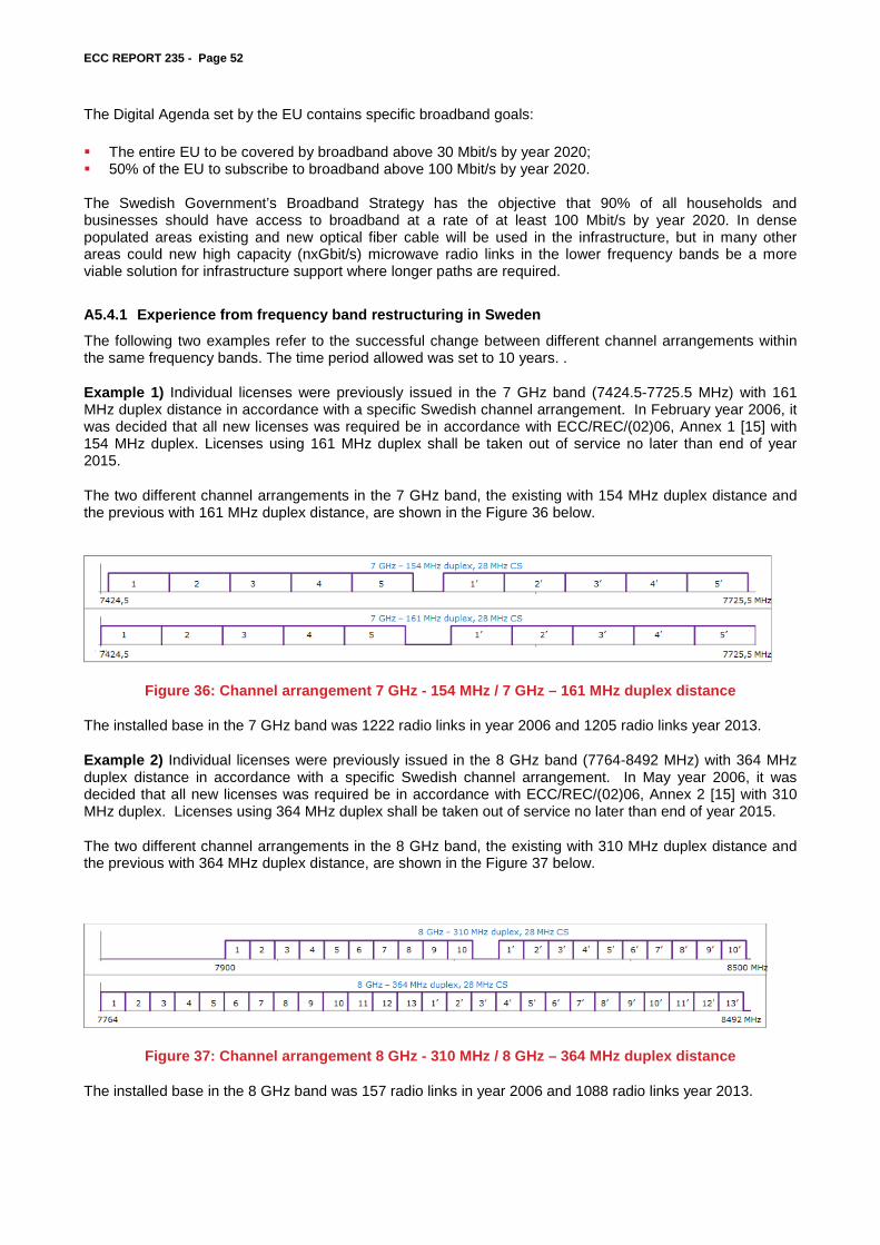
ECC REPORT 235 - Page 52
The Digital Agenda set by the EU contains specific broadband goals:
The entire EU to be covered by broadband above 30 Mbit/s by year 2020; 50% of the EU to subscribe to broadband above 100 Mbit/s by year 2020. The Swedish Government’s Broadband Strategy has the objective that 90% of all households and businesses should have access to broadband at a rate of at least 100 Mbit/s by year 2020. In dense populated areas existing and new optical fiber cable will be used in the infrastructure, but in many other areas could new high capacity (nxGbit/s) microwave radio links in the lower frequency bands be a more viable solution for infrastructure support where longer paths are required.
A5.4.1 Experience from frequency band restructuring in Sweden
The following two examples refer to the successful change between different channel arrangements within the same frequency bands. The time period allowed was set to 10 years. .
Example 1) Individual licenses were previously issued in the 7 GHz band (7424.5-7725.5 MHz) with 161 MHz duplex distance in accordance with a specific Swedish channel arrangement. In February year 2006, it was decided that all new licenses was required be in accordance with ECC/REC/(02)06, Annex 1 [15] with 154 MHz duplex. Licenses using 161 MHz duplex shall be taken out of service no later than end of year 2015.
The two different channel arrangements in the 7 GHz band, the existing with 154 MHz duplex distance and the previous with 161 MHz duplex distance, are shown in the Figure 36 below.
Figure 36: Channel arrangement 7 GHz - 154 MHz / 7 GHz – 161 MHz duplex distance
The installed base in the 7 GHz band was 1222 radio links in year 2006 and 1205 radio links year 2013.
Example 2) Individual licenses were previously issued in the 8 GHz band (7764-8492 MHz) with 364 MHz duplex distance in accordance with a specific Swedish channel arrangement. In May year 2006, it was decided that all new licenses was required be in accordance with ECC/REC/(02)06, Annex 2 [15] with 310 MHz duplex. Licenses using 364 MHz duplex shall be taken out of service no later than end of year 2015.
The two different channel arrangements in the 8 GHz band, the existing with 310 MHz duplex distance and the previous with 364 MHz duplex distance, are shown in the Figure 37 below.
Figure 37: Channel arrangement 8 GHz - 310 MHz / 8 GHz – 364 MHz duplex distance
The installed base in the 8 GHz band was 157 radio links in year 2006 and 1088 radio links year 2013.
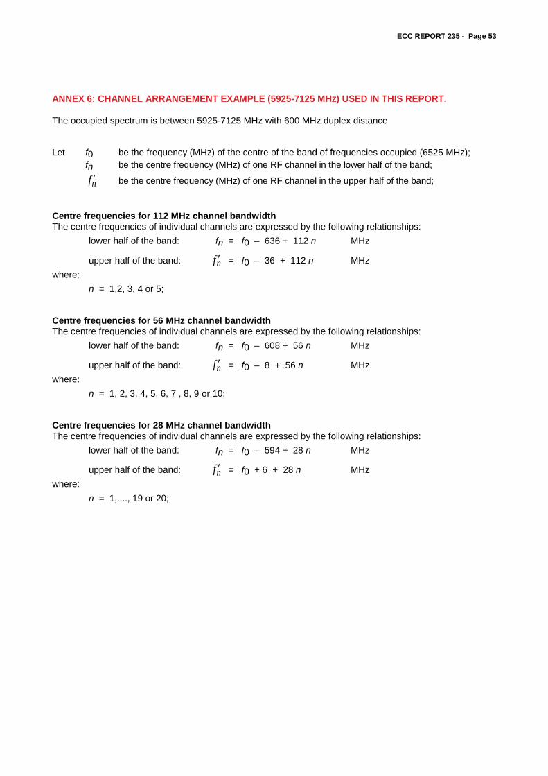
ECC REPORT 235 - Page 53
ANNEX 6: CHANNEL ARRANGEMENT EXAMPLE (5925-7125 MHZ) USED IN THIS REPORT.
The occupied spectrum is between 5925-7125 MHz with 600 MHz duplex distance
Let f0 be the frequency (MHz) of the centre of the band of frequencies occupied (6525 MHz); fn be the centre frequency (MHz) of one RF channel in the lower half of the band;
nf ′ be the centre frequency (MHz) of one RF channel in the upper half of the band; Centre frequencies for 112 MHz channel bandwidth The centre frequencies of individual channels are expressed by the following relationships: lower half of the band: fn = f0 – 636 + 112 n MHz
upper half of the band: nf ′ = f0 – 36 + 112 n MHz where: n = 1,2, 3, 4 or 5; Centre frequencies for 56 MHz channel bandwidth The centre frequencies of individual channels are expressed by the following relationships: lower half of the band: fn = f0 – 608 + 56 n MHz
upper half of the band: nf ′ = f0 – 8 + 56 n MHz where: n = 1, 2, 3, 4, 5, 6, 7 , 8, 9 or 10; Centre frequencies for 28 MHz channel bandwidth The centre frequencies of individual channels are expressed by the following relationships: lower half of the band: fn = f0 – 594 + 28 n MHz
upper half of the band: nf ′ = f0 + 6 + 28 n MHz where: n = 1,...., 19 or 20;
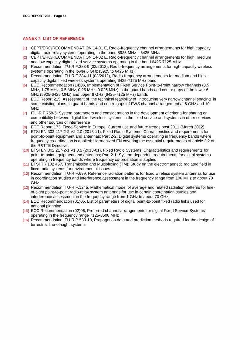
ECC REPORT 235 - Page 54
ANNEX 7: LIST OF REFERENCE
[1] CEPT/ERC/RECOMMENDATION 14-01 E, Radio-frequency channel arrangements for high capacity digital radio-relay systems operating in the band 5925 MHz – 6425 MHz.
[2] CEPT/ERC/RECOMMENDATION 14-02 E, Radio-frequency channel arrangements for high, medium and low capacity digital fixed service systems operating in the band 6425-7125 MHz.
[3] Recommendation ITU-R F.383-9 (02/2013), Radio-frequency arrangements for high-capacity wireless systems operating in the lower 6 GHz (5925 to 6425 MHz),
[4] Recommendation ITU-R F.384-11 (03/2012), Radio-frequency arrangements for medium and high-capacity digital fixed wireless systems operating 6425-7125 MHz band
[5] ECC Recommendation (14)06, Implementation of Fixed Service Point-to-Point narrow channels (3.5 MHz, 1.75 MHz, 0.5 MHz, 0.25 MHz, 0.025 MHz) in the guard bands and centre gaps of the lower 6 GHz (5925-6425 MHz) and upper 6 GHz (6425-7125 MHz) bands
[6] ECC Report 215, Assessment of the technical feasibility of introducing very narrow channel spacing in some existing plans, in guard bands and centre gaps of FWS channel arrangement at 6 GHz and 10 GHz
[7] ITU-R F.758-5, System parameters and considerations in the development of criteria for sharing or compatibility between digital fixed wireless systems in the fixed service and systems in other services and other sources of interference
[8] ECC Report 173, Fixed Service in Europe, Current use and future trends post 2011 (March 2012) [9] ETSI EN 302 217-2-2 V2.2.0 (2013-11), Fixed Radio Systems; Characteristics and requirements for
point-to-point equipment and antennas; Part 2-2: Digital systems operating in frequency bands where frequency co-ordination is applied; Harmonized EN covering the essential requirements of article 3.2 of the R&TTE Directive.
[10] ETSI EN 302 217-2-1 V1.3.1 (2010-01), Fixed Radio Systems; Characteristics and requirements for point-to-point equipment and antennas; Part 2-1: System-dependent requirements for digital systems operating in frequency bands where frequency co-ordination is applied
[11] ETSI TR 102 457, Transmission and Multiplexing (TM); Study on the electromagnetic radiated field in fixed radio systems for environmental issues.
[12] Recommendation ITU-R F.699, Reference radiation patterns for fixed wireless system antennas for use in coordination studies and interference assessment in the frequency range from 100 MHz to about 70 GHz
[13] Recommendation ITU-R F.1245, Mathematical model of average and related radiation patterns for line-of-sight point-to-point radio-relay system antennas for use in certain coordination studies and interference assessment in the frequency range from 1 GHz to about 70 GHz.
[14] ECC Recommendation (01)05, List of parameters of digital point-to-point fixed radio links used for national planning
[15] ECC Recommendation (02)06, Preferred channel arrangements for digital Fixed Service Systems operating in the frequency range 7125-8500 MHz
[16] Recommendation ITU-R P.530-10, Propagation data and prediction methods required for the design of terrestrial line-of-sight systems
Related Documents