ECAT-261x EtherCAT to Modbus RTU Gateway Module User Manual English Ver. 1.5.0, May 2019 WARRANTY All products manufactured by ICP DAS are warranted against defective materials for a period of one year from the date of delivery to the original purchaser. WARNING ICP DAS assumes no liability for damages consequent to the use of this product. ICP DAS reserves the right to change this manual at any time without notice. The information furnished by ICP DAS is believed to be accurate and reliable. However, no responsibility is assumed by ICP DAS for its use, nor for any infringements of patents or other rights of third parties resulting from its use. COPYRIGHT Copyright © 2019 by ICP DAS. All rights reserved. TRADEMARKS Names are used for identification purposes only and may be registered trademarks of their respective companies. CONTACT US If you have any questions, feel free to contact us via email at: [email protected] SUPPORT This manual relates to the following modules: ECAT-2060, ECAT-2060-DW and ECAT-2611

Welcome message from author
This document is posted to help you gain knowledge. Please leave a comment to let me know what you think about it! Share it to your friends and learn new things together.
Transcript

ECAT-261x EtherCAT to Modbus RTU Gateway Module User Manual English Ver. 1.5.0, May 2019
WARRANTY All products manufactured by ICP DAS are warranted against defective materials for a period of one year from the date of delivery to the original purchaser. WARNING ICP DAS assumes no liability for damages consequent to the use of this product. ICP DAS reserves the right to change this manual at any time without notice. The information furnished by ICP DAS is believed to be accurate and reliable. However, no responsibility is assumed by ICP DAS for its use, nor for any infringements of patents or other rights of third parties resulting from its use. COPYRIGHT Copyright © 2019 by ICP DAS. All rights reserved. TRADEMARKS Names are used for identification purposes only and may be registered trademarks of their respective companies. CONTACT US If you have any questions, feel free to contact us via email at: [email protected]
SUPPORT This manual relates to the following modules: ECAT-2060, ECAT-2060-DW and ECAT-2611

EtherCAT to Modbus RTU Gateway
Copyright © 2019 ICP DAS CO., Ltd. All Rights Reserved. - 2 -
TABLE OF CONTENTS PACKING LIST ............................................................................................................................................................. 6
MORE INFORMATION ................................................................................................................................................ 6
1. INTRODUCTION ................................................................................................................................................ 7
1.1 FEATURES .............................................................................................................................................................. 8 1.2 BLOCK DIAGRAM .................................................................................................................................................... 9
2. HARDWARE INFORMATION ........................................................................................................................... 10
2.1 APPEARANCE ....................................................................................................................................................... 10 2.2 SPECIFICATION ..................................................................................................................................................... 12 2.3 PIN ASSIGNMENTS ................................................................................................................................................ 13
EtherCAT Interface ..................................................................................................................................................... 13 COM1 (Console Port) ................................................................................................................................................. 13 COM2/COM3 (Modbus RTU) ..................................................................................................................................... 13
2.4 WIRING CONNECTIONS .......................................................................................................................................... 14 3-wire RS-232 Wiring ................................................................................................................................................. 14 4-wire RS-422 Wiring ................................................................................................................................................. 14 2-wire RS-485 Wiring ................................................................................................................................................. 14
2.5 INIT/NORMAL OPERATING MODE ............................................................................................................................ 15 2.6 DIMENSIONS ........................................................................................................................................................ 16
3. GETTING STARTED ......................................................................................................................................... 17
3.1 FACTORY DEFAULT SETTINGS ................................................................................................................................... 17 3.2 CONNECTING THE POWER AND THE HOST PC ............................................................................................................. 18 3.3 CONNECTING THE POWER METER (FOR ECAT-2610-DW) ....................................................................................................... 20 3.4 SEARCH MODULES ................................................................................................................................................ 22 3.5 CHECK STATUS ...................................................................................................................................................... 25
3.5.1 Module Status and Error Mode ........................................................................................................................ 27 ECAT-2610/2611 ...................................................................................................................................................................... 28 ECAT-2610-DW ......................................................................................................................................................................... 30
4. MODBUS RTU DEVICE SETUP ........................................................................................................................ 32
4.1 CONFIGURING THE MODBUS RTU DEVICE ................................................................................................................. 33 4.2 CONFIGURING AND UPLOADING .............................................................................................................................. 36
4.2.1 Restore to Factory Defaults Settings ................................................................................................................ 44 4.3 TESTING THE MODBUS RTU SLAVE .......................................................................................................................... 47
5. MODBUS RTU MASTER SETUP....................................................................................................................... 51
5.1 CONFIGURING AND UPLOADING .............................................................................................................................. 51 5.2 CONNECTING THE MODBUS RTU MASTER ................................................................................................................ 56

EtherCAT to Modbus RTU Gateway
Copyright © 2019 ICP DAS CO., Ltd. All Rights Reserved. - 3 -
5.3 TESTING THE MODBUS RTU MASTER ....................................................................................................................... 60
6. MODBUS INFORMATION ................................................................................................................................ 65
FC1(0X01) READ MULTIPLE COILS (0XXXX) FOR DO ................................................................................................................. 68 FC2(0X02) READ MULTIPLE INPUT DISCRETE (1XXXX) FOR DI ..................................................................................................... 69 FC3(0X03) READ MULTIPLE REGISTERS (4XXXX) FOR AO ........................................................................................................... 70 FC4(0X04) READ MULTIPLE INPUT REGISTERS (3XXXX) FOR AI ................................................................................................... 71 FC5(0X05) WRITE SINGLE COIL (0XXXX) FOR DO ..................................................................................................................... 72 FC6(0X06) WRITE SINGLE REGISTER (4XXXX) FOR AO .............................................................................................................. 73 FC15(0X0F) FORCE MULTIPLE COILS (0XXXX) FOR DO .............................................................................................................. 74 FC16(0X10) WRITE MULTIPLE REGISTERS (4XXXX) FOR AO ....................................................................................................... 75 FC255(0XFF) SPECIAL COMMANDS ....................................................................................................................................... 76
7. UPLOAD COMMANDS.TXT OPERATIONS ...................................................................................................... 77
8. DISTRIBUTED CLOCKS (FOR ECAT-2610) .................................................................................................... 82
8.1 MODBUS RTU TIMING .......................................................................................................................................... 82 8.2 DC CONFIGURATION AND OPERATION ...................................................................................................................... 88
9. OBJECT DESCRIPTION AND PARAMETERIZATION ...................................................................................... 96
9.1 STANDARD OBJECTS .............................................................................................................................................. 96 9.2 SPECIFIC OBJECTS ................................................................................................................................................. 97
Input Buffer ............................................................................................................................................................... 97 Output Buffer ............................................................................................................................................................ 97
10. APPLICATIONS ............................................................................................................................................ 98
10.1 THE ICPDAS FAMILY OF ECAT PRODUCTS ................................................................................................................. 98 10.2 ODMS ARE WELCOME ........................................................................................................................................ 101
APPENDICES ............................................................................................................................................................105
A1. HOW DO I RETRIEVE THE MODBUS COMMAND VIA DCON UTILITY? ..................................................................................... 105 A2. CONFIGURATION FILE REFERENCE FOR ECAT-2610 ........................................................................................................... 106
00. Baudrate ............................................................................................................................................................ 107 115200_N81_Init.txt ............................................................................................................................................................. 107 9600_N81.txt ......................................................................................................................................................................... 108 19200_N82.txt ....................................................................................................................................................................... 108 38400_E81.txt ........................................................................................................................................................................ 109 57600_O81.txt ....................................................................................................................................................................... 109
01. DIO .................................................................................................................................................................... 110 DIO_Addr01_1.txt ................................................................................................................................................................. 110 DIO_Addr01_2.txt ................................................................................................................................................................. 111 DIO_Addr01_3.txt ................................................................................................................................................................. 112 DIO_Addr01_4.txt ................................................................................................................................................................. 113
02. DA ...................................................................................................................................................................... 114 DA_Addr02_1.txt ................................................................................................................................................................... 114

EtherCAT to Modbus RTU Gateway
Copyright © 2019 ICP DAS CO., Ltd. All Rights Reserved. - 4 -
DA_Addr02_2.txt ................................................................................................................................................................... 115 DA_Addr02_3.txt ................................................................................................................................................................... 116 DA_Addr02_4.txt ................................................................................................................................................................... 117 DA_Addr02_5.txt ................................................................................................................................................................... 118
03. AD ...................................................................................................................................................................... 119 AD_Addr03_1.txt ................................................................................................................................................................... 119 AD_Addr03_2.txt ................................................................................................................................................................... 120
04. DIO_DA_AD ....................................................................................................................................................... 121 DIO_DA_AD_1.txt .................................................................................................................................................................. 121
05. Rising_Trigger.................................................................................................................................................... 122 RisingTrigger _1.txt ................................................................................................................................................................ 122 RisingTrigger _2.txt ................................................................................................................................................................ 123 RisingTrigger _3.txt ................................................................................................................................................................ 124
06. Initial_Value ...................................................................................................................................................... 125 Init_Value _1.txt .................................................................................................................................................................... 125
07. Swap_Byte_Word .............................................................................................................................................. 127 Both_Swap _1.txt .................................................................................................................................................................. 127 Byte_Swap _1.txt .................................................................................................................................................................. 128 Word_Swap _1.txt ................................................................................................................................................................. 129
08. State_Change_Trigger ....................................................................................................................................... 130 State_Change _1.txt .............................................................................................................................................................. 130 State_Change _2.txt .............................................................................................................................................................. 131
09. Constant_Output ............................................................................................................................................... 132 Constant _1.txt ...................................................................................................................................................................... 132
10. Bit_Command .................................................................................................................................................... 133 Bit _Cmd_1.txt ....................................................................................................................................................................... 133
11. Delay_Command ............................................................................................................................................... 134 Delay_Cmd_1.txt ................................................................................................................................................................... 134
12. TxPdo_RxPdo_0x80_0xFF .................................................................................................................................. 135 TxPdo_RxPdo_0x80.txt ......................................................................................................................................................... 135 TxPdo_RxPdo_0xFF.txt .......................................................................................................................................................... 135 TxPdo_RxPdo_AD_0x80.txt ................................................................................................................................................... 136 TxPdo_RxPdo_AD_0xFF.txt ................................................................................................................................................... 136 TxPdo_RxPdo_DA_0x80_0xFF.txt .......................................................................................................................................... 137
13. Commands_128_202 ........................................................................................................................................ 137 14. End_of_Cmd_Dealy ........................................................................................................................................... 138
End_Delay_1.txt .................................................................................................................................................................... 138 15. TxPdo_RxPdo_Max ............................................................................................................................................ 139
TxRxPdo_Max_1.txt .............................................................................................................................................................. 139 TxRxPdo_Max_2.txt .............................................................................................................................................................. 140 TxRxPdo_Max_3.txt .............................................................................................................................................................. 140
16. Rs485_Cycle_Time ............................................................................................................................................. 141 Rs485_Cycle_Time_1.txt ....................................................................................................................................................... 141

EtherCAT to Modbus RTU Gateway
Copyright © 2019 ICP DAS CO., Ltd. All Rights Reserved. - 5 -
Rs485_Cycle_Time_2.txt ....................................................................................................................................................... 142 17. Ext_Sync ............................................................................................................................................................ 143
ext_sync.txt ........................................................................................................................................................................... 144 A3. CONFIGURATION FILE REFERENCE FOR ECAT-2610-DW .................................................................................................... 146
01. 32_bit_Read_Power_Meter .............................................................................................................................. 147 02. 16_bit_Read_System ......................................................................................................................................... 148 03. 8_bit_DO0_DO1 ................................................................................................................................................ 148
DO0_DO1.txt ......................................................................................................................................................................... 148 DO0_DO1_2.txt ..................................................................................................................................................................... 149
04. 16_bit_Set_Parameter ...................................................................................................................................... 149 05. 8_16_32_Full ..................................................................................................................................................... 150 06. to_meterX3 ........................................................................................................................................................ 151 07. to_meterX6 ........................................................................................................................................................ 152 08. TEST ................................................................................................................................................................... 153
TEST_4A.txt ........................................................................................................................................................................... 153 TEST_5A_8.txt........................................................................................................................................................................ 153 TEST_5B_16.txt ...................................................................................................................................................................... 154 TEST_5C_32.txt ...................................................................................................................................................................... 154 TEST_5D_16.txt ..................................................................................................................................................................... 154 TEST_5E_2.txt ........................................................................................................................................................................ 155
A4. MANUALLY CONFIGURE AND UPLOAD ............................................................................................................................. 156 A4-1 Configuration Data ......................................................................................................................................... 156
Edit the configuration data of ECAT-2610 ............................................................................................................................. 156 Edit the configuration data of ECAT-2610-DW ...................................................................................................................... 160 Edit the configuration data of ECAT-2611 ............................................................................................................................. 164
A4-2 Upload Configuration Data ............................................................................................................................. 166 A5. INTEGRATION WITH ICP DAS MODBUS RTU PRODUCTS .................................................................................................... 171 A6. REVISION HISTORY ...................................................................................................................................................... 172

EtherCAT to Modbus RTU Gateway
Copyright © 2019 ICP DAS CO., Ltd. All Rights Reserved. - 6 -
Packing List The shipping package contains the following items:
NOTE
If any of these items is missing or damaged, contact your local distributor for more information. Keep the shipping materials and overall package in case you need to return the module in the future.
More Information Manual/Quick Start/Datasheet: http://ftp.icpdas.com/pub/cd/fieldbus_cd/ethercat/slave/ecat-2000/manual/ XML Device Description (ESI): http://ftp.icpdas.com/pub/cd/fieldbus_cd/ethercat/slave/ecat-2000/software/
FAQ: http://www.icpdas.com/root/support/faq/faq.html
ECAT-2610(-DW)/2611 x 1 Quick Start x 1 CA-0915 Cable x 1

EtherCAT to Modbus RTU Gateway
Copyright © 2019 ICP DAS CO., Ltd. All Rights Reserved. - 7 -
1. Introduction The ECAT-2610(-DW)/2611 Communicator is a proven and trusted protocol converter gateway module that can be used to connect non-networked industrial devices and equipment to an EtherCAT system.
The ECAT-2610 allows serial-based RS-232/422/485 industrial devices and equipment to be easily integrated into an EtherCAT control system without the need to make any changes to the device. Simply connect the ECAT-2610 and configure the device and you are ready to go. The ECAT-2610-DW is a DWORD version of ECAT-2610 that is suitable for Smart Power Meters PM-3000 series.
The ECAT-2611 provides a data exchange buffer that allows two different systems (EtherCAT Master and the Modbus RTU Master) exchange data easily and faster for more diverse applications.

EtherCAT to Modbus RTU Gateway
Copyright © 2019 ICP DAS CO., Ltd. All Rights Reserved. - 8 -
1.1 Features
Powerful MCU that efficiently manages network traffic. Two RJ-45 bus EtherCAT connectors for Daisy-Chain Wiring Allows system integration engineers to retrofit older automation devices into modern EtherCAT
communication structures. Requires no adjustments to be made to the hardware or software on the connected device. Compatible with all PLCs that provide EtherCAT support. Performs complete serial protocol conversion, no PLC function blocks required. ECAT-2610 Enable serial-based RS-232/422/485 devices to be integrated into an EtherCAT network via an
EtherCAT interface. Supports a maximum of 256 WORD of input data and 256 WORD of output data. Supports serial port interface.
Supports Modbus RTU (Master) protocol Supports RS-232/422/485 Port Supports Max. Baud Rate 115200 bps
ECAT-2610-DW Supports a maximum of 128 WORD of input data and 128 WORD of output data. Supports dedicated configuration file examples and ESI file for PM-3033/3133/3114/3112. Max. connections PM-3033/3133 Power Meter: 6 pcs Mixable with other Modbus RTU slaves. Supports serial port interface.
Supports Modbus RTU (Master) protocol Supports RS-232/422/485 Port Supports Max. Baud Rate 115200 bps
ECAT-2611 Transfer of I/O data between two networks. Supports a maximum of 256 WORD of input data and 256 WORD of output data. Supports serial port interface.
Supports Modbus RTU (Slave) protocol Supports RS-232/422/485 Port Supports Max. Baud Rate 115200 bps Supports Modbus Function code 03, 04, 06 and 16

EtherCAT to Modbus RTU Gateway
Copyright © 2019 ICP DAS CO., Ltd. All Rights Reserved. - 9 -
1.2 Block Diagram The following is the block diagram for the ECAT-2610(-DW)/2611 module:
Figure 1-2 Block Diagram for the ECAT-2610(-DW)/2611

EtherCAT to Modbus RTU Gateway
Copyright © 2019 ICP DAS CO., Ltd. All Rights Reserved. - 10 -
2. Hardware Information
2.1 Appearance
1. EtherCAT Bus Status Indicators
Notation Color State Description
RUN Red
OFF The device is in the INIT state
Blinking The device is in the PRE-OPETARIONAL state
Single Flash The device is in the SAFE-OPERATIONAL state
ON The device is in the OPETARIONAL state
Link Activity IN/OUT Green
OFF No connection established
Flashing Connection established and there is network activity
ON Connection established but there is not network activity
5. DC Power Input Connector
6. EtherCAT Interface
4. COM2/COM3 (Modbus RTU)
3. COM1 (Console Port)
2. ECAT-2610(-DW)/2611 Status Indicators
1. EtherCAT Bus Status Indicators
Front Panel Top Panel

EtherCAT to Modbus RTU Gateway
Copyright © 2019 ICP DAS CO., Ltd. All Rights Reserved. - 11 -
2. ECAT-2610(-DW)/2611 Status Indicators
Notation Color State Description
Err Red OFF Normal operation
Blinking An error has occurred
Mode Green
Flashing once every 0.3 seconds DC enabled
Flashing once every 1 seconds Normal operation
Flashing once every 2 seconds No configuration file or there is an error in the configuration data
Flashing once every 4 seconds Configuration CRC error
Modbus Green OFF No Modbus Command
Flashing once every 1 seconds Normal operation
3. COM1 (Console Port, DB9-Male)
COM1 is the Configuration/Diagnostic Port. For more detailed information related to the pin
assignments for the Console Port, refer to Section 2.3 “Pin Assignments”.
4. COM2/COM3 (Modbus RTU)
COM2 and COM3 are used to connect to Modbus RTU devices. For more detailed information
related to the pin assignments for the Modbus COM Ports, refer to Section 2.3 “Pin Assignments”.
5. DC Power Input Connector The “PWR(+)” and “GND(-)” pins are used to connect the power supply and is common to all types of ECAT-2610(-DW)/2611 module. The valid power voltage range is from +12 to +48 VDC. “F.G.” (Frame Ground): Electronic circuits are constantly vulnerable to Electrostatic Discharge (ESD), which becomes worse in a continental climate area. The ECAT-2610(-DW)/2611 module features a new design for the frame ground, which provides a path that bypasses ESD, resulting in enhanced ESD protection capabilities and ensuring that the module is more reliable.
6. EtherCAT Interface ECAT-2610(-DW)/2611 module is equipped with two RJ-45 EtherCAT Interface ports. The IN port is the EtherCAT signal input port that can be connected to either the EtherCAT Master or the signal output from the previous EtherCAT slave module. The OUT port is the EtherCAT signal output that is connected to the EtherCAT signal input on the next EtherCAT slave module.

EtherCAT to Modbus RTU Gateway
Copyright © 2019 ICP DAS CO., Ltd. All Rights Reserved. - 12 -
2.2 Specification Model ECAT-2610(-DW) ECAT-2611 Protocol Protocol EtherCAT
RJ-45 Port RJ-45 x 1 Max. distance between stations: 100 m (100BASE-TX) Data Transfer Medium: Ethernet/EtherCAT Cable (Min.CAT 5e)
Communication Protocol Modbus RTU (Master) Modbus RTU (Slave)
Serial Interface
RS-232 Note that the RS-232, RS-422 and RS-485 interfaces cannot be used simultaneously TxD, RxD, GND TxD+, TxD-, RxD+, RxD- Data+, Data-
RS-422 RS-485
Power Input Redundant Input Range +12 ~ +48 VDC Power Consumption 0.1 A @ 24 VDC Protection Power reverse polarity protection Connector 3-pin Removable Terminal Block (5.08 mm) Mechanical Dimensions (H x W x D) 110 mm x 90 mm x 33 mm Installation DIN-Rail Mounting Environment Operating Temperature -25 to +75°C Storage Temperature -30 to +80°C Relative Humidity 10 to 90% RH, Non-condensing

EtherCAT to Modbus RTU Gateway
Copyright © 2019 ICP DAS CO., Ltd. All Rights Reserved. - 13 -
2.3 Pin Assignments
EtherCAT Interface
COM1 (Console Port)
COM2/COM3 (Modbus RTU)
Pin Assignment
F.G. GND(-) PWR(+)
IN
OUT
Pin Assignment
Terminal No.
- 01 RxD 02 TxD 03
- 04 GND 05
Terminal No. Pin Assignment
COM2
TxD+/D+ TxD-/D- RxD+ RxD-
N/A
COM3 ISO.GND
TxD RxD
Terminal No.
Pin Assignment
06 - 07 - 08 - 09 -
NOTE Note that the RS-232, RS-422 and RS-485 interfaces cannot be used simultaneously.

EtherCAT to Modbus RTU Gateway
Copyright © 2019 ICP DAS CO., Ltd. All Rights Reserved. - 14 -
2.4 Wiring Connections
3-wire RS-232 Wiring
4-wire RS-422 Wiring
2-wire RS-485 Wiring
NOTE 1. Typically, all the signal grounds on RS-422/485
devices need to be connected together in order to reduce the common-mode voltage between devices.
2. Twisted-pair cable must be used for the DATA+/- wires.
3. Both ends of the twisted-pair cable may require a termination resistor connected across the two wires (DATA+ and DATA-). Typically 120 Ω resistors are used.
4. The Data+ and B pins in the figure are positive-voltage pins, and the Data- and A pins are negative-voltage pins. The B/A pins may be defined differently depending on the device, so ensure that you please check it first.

EtherCAT to Modbus RTU Gateway
Copyright © 2019 ICP DAS CO., Ltd. All Rights Reserved. - 15 -
2.5 Init/Normal Operating Mode The ECAT-2610(-DW)/2611 module provide two operating modes that can be selected, each of which will be described in more detail below.
Init Mode Note that Init Mode should only be selected when troubleshooting. Power off the ECAT-2610(-DW)/2611 module,
and connect the device to the Host PC using the CA-0915 cable.
Short the TxD and RxD pins on the COM3 port to enable Init mode. Launch the 7188ECAT utility on the Host PC and then power on the ECAT-2610(-DW)/2611
module to verify that Init mode has been enabled. Disconnect the wire from the TxD and RxD pins on the COM3 port to return the module to
Normal mode. Erase the EEPROM and upload the new configuration file to the EEPROM. Reboot the ECAT-2610(-DW)/2611 module to operate in Normal mode. For more detailed information about how to perform the above procedure, refer to Chapter 7 “Upload Commands.txt Operation”.
Normal Mode Normal Mode is the default operating mode and should be used in the majority of cases.

EtherCAT to Modbus RTU Gateway
Copyright © 2019 ICP DAS CO., Ltd. All Rights Reserved. - 16 -
2.6 Dimensions The following diagrams illustrate the dimensions of the ECAT-2610(-DW)/2611 and can be used as a reference when defining the specifications for any custom enclosures. All dimensions are in millimeters.
Left Side
Right Side
Front Rear
Top Bottom
EtherCAT to Modbus RTU Gateway
Copyright © 2019 ICP DAS CO., Ltd. All Rights Reserved. - 17 -
3. Getting Started This chapter provides detailed information about how to start using the ECAT-2610(-DW)/2611 module, including details related to the factory default settings and connecting the power supply, etc. which is used to confirm that the device operating correctly.
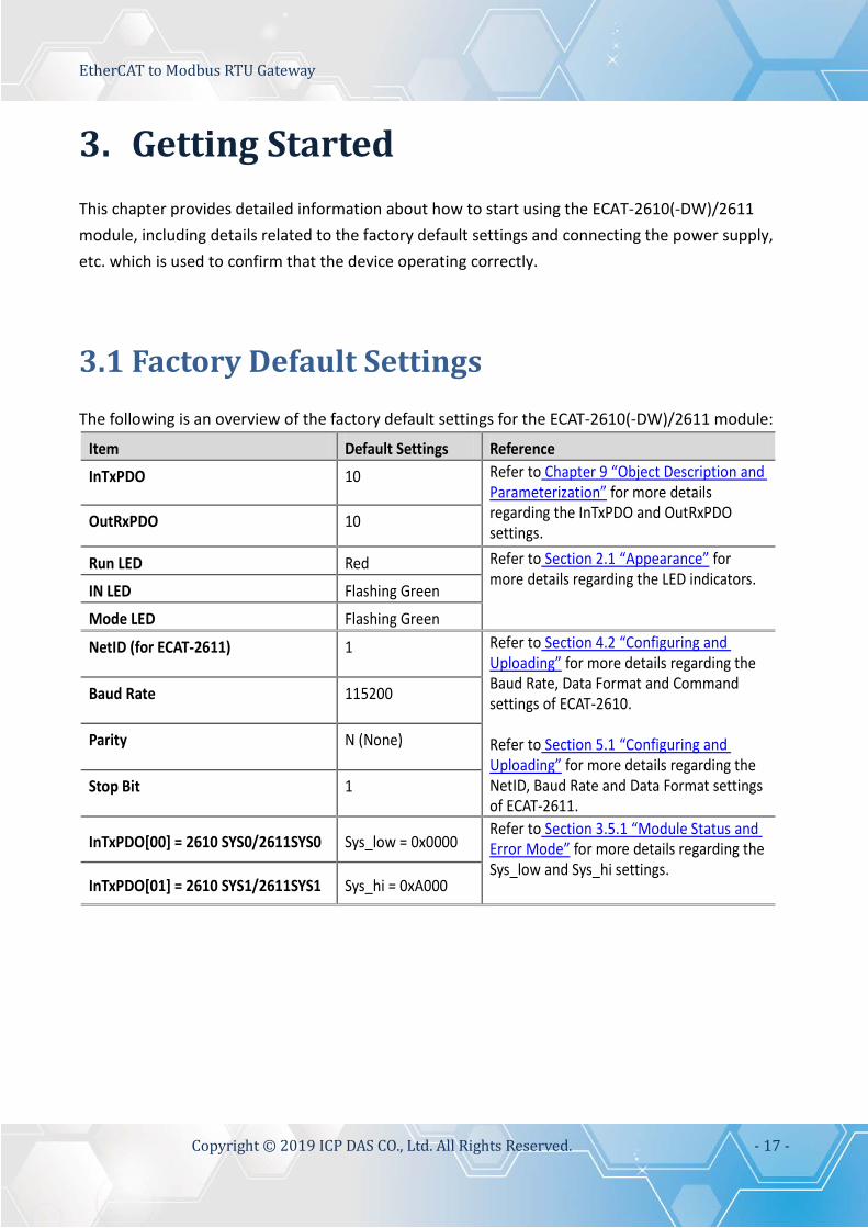
3.1 Factory Default Settings The following is an overview of the factory default settings for the ECAT-2610(-DW)/2611 module:
Item Default Settings Reference InTxPDO 10 Refer to Chapter 9 “Object Description and
Parameterization” for more details regarding the InTxPDO and OutRxPDO settings.
OutRxPDO 10
Run LED Red Refer to Section 2.1 “Appearance” for more details regarding the LED indicators.
IN LED Flashing Green
Mode LED Flashing Green
NetID (for ECAT-2611) 1 Refer to Section 4.2 “Configuring and Uploading” for more details regarding the Baud Rate, Data Format and Command settings of ECAT-2610. Refer to Section 5.1 “Configuring and Uploading” for more details regarding the NetID, Baud Rate and Data Format settings of ECAT-2611.
Baud Rate 115200
Parity N (None)
Stop Bit 1
InTxPDO[00] = 2610 SYS0/2611SYS0 Sys_low = 0x0000 Refer to Section 3.5.1 “Module Status and Error Mode” for more details regarding the Sys_low and Sys_hi settings.
InTxPDO[01] = 2610 SYS1/2611SYS1 Sys_hi = 0xA000

EtherCAT to Modbus RTU Gateway
Copyright © 2019 ICP DAS CO., Ltd. All Rights Reserved. - 18 -
3.2 Connecting the Power and the Host PC
Step 1 Connect the IN port on the ECAT-2610(-DW)/2611 to the RJ-45 Ethernet port on the Host PC.
Ensure that the network settings on the Host PC have been correctly configured and the connection
is functioning normally. Ensure that the Windows or 3rd-party firewall or any Anti-virus software is
properly configured to allow incoming connections, or temporarily disable these functions.
NOTE Attaching an ESC (EtherCAT Slave Controller) directly to an office network will result in network flooding, since the ESC will reflect any frame – especially broadcast frames – back into the network (broadcast storm). Connect the Host device to the IN Port on the ECAT-2610(-DW)/2611. Connect the PWR(+) pin on the ECAT-2610(-DW)/2611 to the positive terminal on a +12 VDC to +48 VDC power supply, and connect the GND(-) pin on the ECAT-2610(-DW)/2611 to the negative terminal.
Top Panel
Ethernet Cable
Figure 3-2.1
External Power

EtherCAT to Modbus RTU Gateway
Copyright © 2019 ICP DAS CO., Ltd. All Rights Reserved. - 19 -
Step 2 Verify that the LEDs indicators on the ECAT-2610(-DW)/2611 are illuminated as illustrated below: Once the power is connected, the “IN” and “Mode” LEDs should be flash in green. Once the ECAT-2610(-DW)/2611 connected to EtherCAT Master, the “Run” LED should be illuminated in red.
IN = Green Flashing
Mode = Green Flashing
RUN = Red Run
IN
Figure 3-2.2

EtherCAT to Modbus RTU Gateway
Copyright © 2019 ICP DAS CO., Ltd. All Rights Reserved. - 20 -
3.3 Connecting the Power Meter (for ECAT-2610-DW) This section only applies to ECAT-2610-DW. Please skip this section for other models. Note that ECAT-2610-DW only supports PM-3033, PM-3133, PM-3114 and PM-3112 Series Smart Power Meter. Here, the PM-3133 is used as an example.
Step 1 Connect the PM-3133 Power Meter to the ECAT-2610-DW Setting PM-3133’s Modbus RTU address, Baud Rate and Wiring Mode to match the command file of ECAT-2610-DW, as follows:
Set the Modbus address is 4 via DIP Switch 1 to 6, i.e. ON, ON, OFF, OFF, OFF, OFF.
Set the Baud Rate is 115200 via DIP Switch 7 to 8, i.e. ON, ON.
Set the Wiring Mode is 3P3W-3CT via DIP Switch 9 to 10, i.e. OFF, ON.
Figure 3-3.1
Figure 3-3.2
Figure 3-3.3

EtherCAT to Modbus RTU Gateway
Copyright © 2019 ICP DAS CO., Ltd. All Rights Reserved. - 21 -
Check the current input terminal and connect the CT’s then close the CT chip. Connect the PM-3133 using a RS-485 wiring to the COM2 on ECAT-2610-DW. Supply power to the PM-3133 (+12 to +48 VDC Power used).
NOTES 1. For detailed information regarding hardware configuration, CT’s installation, power supply and wiring, etc. for the PM-3133 Series, refer to Quick Start (http://ftp.icpdas.com/pub/cd/powermeter/pm-3133/quickstartguide/) or User Manual (http://ftp.icpdas.com/pub/cd/powermeter/pm-3133/user'smanual/) 2. If your power meter is another models (e.g., PM-3030, PM-3114 or PM-3112), refer to the Quick Start or User Manual for that specific power meter.
RS-485 wiring
DC Power Supply +12 to +48 VDC
Figure 3-3.4

EtherCAT to Modbus RTU Gateway
Copyright © 2019 ICP DAS CO., Ltd. All Rights Reserved. - 22 -
3.4 Search Modules Before following the steps below, you must first install the EtherCAT Master software (e.g., Beckhoff TwinCAT). In this example, we will use Beckhoff TwinCAT 2.x to configuring and operating the ECAT-2610(-DW)/2611, and Beckhoff TwinCAT 2.X is the most commonly used EtherCAT Master Software.
NOTE
Install the latest XML device description(ESI) Ensure that the latest XML device description has been installed in the appropriate TwinCAT folder. The ESI file can be downloaded from the ICP DAS web site (http://ftp.icpdas.com/pub/cd/fieldbus_cd/ethercat/slave/ecat-2000/software/), and should be installed according to the installation instructions.
Step 1 Install the ESI file
Copy the “ICPDAS ECAT-2610.xml”, “ICPDAS ECAT-2610DW.xml”or “ICPDAS ECAT-2611.xml” file to the appropriate Master Tools installation folder, as indicated in the table below.
Software Default Path Beckhoff EtherCAT Configuration C:\EtherCAT Configurator\EtherCAT Beckhoff TwinCAT 3.X C:\TwinCAT\3.x\Config\Io\EtherCAT Beckhoff TwinCAT 2.X C:\TwinCAT\Io\EtherCAT
Step 2 Automatic Scanning
The EtherCAT system must be in a safe, de-energized state before the ECAT-2610(-DW)/2611 is
connected to the EtherCAT network!
Switch on the operating power supply, launch the TwinCAT System Manager (Config mode),
and scan in the devices, as illustrated in the image below. Click the “OK” button for all dialogs
when requested, ensuring that the configuration is set to “FreeRun” mode. NOTE
The ECAT-2610-DW confirms that it has been connected to the Power Meter before scanning. Please refer to Section 3.3 “Connecting the Power Meter (for ECAT-2610-DW)” for more details.

EtherCAT to Modbus RTU Gateway
Copyright © 2019 ICP DAS CO., Ltd. All Rights Reserved. - 23 -
Scan the configuration by right-clicking the “I/O Devices” item in the left-hand pane of the TwinCAT System Manager and selecting the “Scan Devices…” option.
Figure 3-4.1
Click “OK” button
Choose the correct network device which is connected to ECAT-2610(-DW)/2611, and click “OK” button
Click “OK” to start scanning Click “OK” to activate the free run mode for TwinCAT system manager
Figure 3-4.2
Figure 3-4.3
Figure 3-4.4

EtherCAT to Modbus RTU Gateway
Copyright © 2019 ICP DAS CO., Ltd. All Rights Reserved. - 24 -
In the left-hand window, the module name is now shown in the TwinCAT system Manager, as follows: For ECAT-2610/2611
For PM-3000 Series Power Meter
Figure 3-4.6
Figure 3-4.5

EtherCAT to Modbus RTU Gateway
Copyright © 2019 ICP DAS CO., Ltd. All Rights Reserved. - 25 -
3.5 Check Status In the left-hand pane of the TwinCAT System Manager, click the entry for the EtherCAT device you wish to configure. For ECAT-2610/2611: Click the “TxPDO
0x00-0x7F” entry in the left-hand pane to retrieve the current configuration settings.
For PM-3000 Series Power Meter: Click
the “PM Inputs Channel 1” entry in the left-hand pane to retrieve the current configuration settings.
Figure 3-5.2
Figure 3-5.1

EtherCAT to Modbus RTU Gateway
Copyright © 2019 ICP DAS CO., Ltd. All Rights Reserved. - 26 -
In the right-hand pane of the TwinCAT System Manager window, check that the Sys_hi value, as follows: For ECAT-2610/2611: 2610/2611SYS1 = 0xA000 = Normal Running.
For PM-3000 Series Power Meter: 2610SYS = 0xA0000000 = Normal Running.
NOTE For more detailed information related to the status settings for the ECAT-2610(-DW)/2611, refer to Section 3.4.1 “Module Status and Error Mode”.
Figure 3-5.3
Figure 3-5.4

EtherCAT to Modbus RTU Gateway
Copyright © 2019 ICP DAS CO., Ltd. All Rights Reserved. - 27 -
3.5.1 Module Status and Error Mode
The ECAT-2610(-DW)/2611 will read and verify the configuration data file (commands.txt) from the EEPROM once power is supplied to the ECAT-2610(-DW)/2611. If an error is detected, the ECAT-2610(-DW)/2611 will switch to the error mode, the details of which are described below.
NOTES 1. For detailed information related to the configuration data file (commands.txt), refer to manually configure and upload of Section A4. “Manually Configure and Upload”. 2. The EEPROM is designed to store data that is not changed frequently. It is not suitable for frequent access a large amount of data, and the erase/write cycle is limited, so it should not be changed frequently when testing that it will easily cause damage to the module. If an error occurs, the Err LED indicator will illuminate, as illustrated below:
Err=Red
Err
Figure 3-5.5

EtherCAT to Modbus RTU Gateway
Copyright © 2019 ICP DAS CO., Ltd. All Rights Reserved. - 28 -
ECAT-2610/2611
To determine the source of the error, check the values of the Baud Rate, Data Format parameters and Modbus command, etc., that are found in the InTxPDO[00] or InTxPDO[01] results, the as indicated below table.
Table 3-5.1 (Read): InTxPDO[00] = 2610 SYS0/2611SYS0 = Sys_low values are defined as:
ECAT-2610 ECAT-2611 Bit Description
12-15 N/A 11 InMax/OutMax Error 10 CmdFun Error: Command Function Error, See Chapter 6 “Modbus Information” 09 CmdLen Error: Command Length Error, See Chapter 6 “Modbus Information” 08 CmdNum Error: Command Number Error, Valid Range: 0 to 300 (Max.) 07 Read EEP CRC Error 06 Address Error 05 Delay Value Error: Valid Range: 0 to 255 ms 04 Timeout Value Error: Valid Range: 0 to 255 ms 03 Stop_bit Error: Valid Values: 1, 2 02 Parity_bit Error: Valid Values: N (None), E (EVEN), O (ODD) 01 Baudrate Error: Valid Values: 1200, 2400, 4800, 9600, 19200, 38400, 57600, 115200 00 Init_pin is short: Enter the Debug Mode, See Chapter 7 “Upload Commands.txt Operation”
Table 3-5.2 (Read): InTxPDO[01] = 2610 SYS1/2611SYS1 = Sys_hi values are defined as:
ECAT-2610 ECAT-2611 Bit Description 15 Exec Baud Rate 3: Valid values refer to following table 3-5.3 1 14 Exec Baud Rate 2: Valid values refer to following table 3-5.3 N/A 13 Exec Baud Rate 1: Valid values refer to following table 3-5.3 N/A 12 Exec Baud Rate 0: Valid values refer to following table 3-5.3 N/A 11 Exec Even Parity: Valid Values: 0 (Not EVEN Parity), 1 (Is EVEN Parity) N/A 10 Exec Odd Parity: Valid Values: 0 (Not ODD Parity), 1 (Is ODD Parity) N/A 09 Exec Stop Bit: Valid Values: 0 (One Stop Bit), 1 (Two Stop Bit) N/A 08 Exec Default = 115200 + N81 N/A 07 N/A N/A 06 N/A N/A 05 Exec Ext_Sync N/A 04 Exec CRC Error 03 Exec return FC (Function Code) Error 02 Exec return Net_ID Error 01 Exec with init value 00 Exec Modbus Timeout

EtherCAT to Modbus RTU Gateway
Copyright © 2019 ICP DAS CO., Ltd. All Rights Reserved. - 29 -
Table 3-5.3: Baud Rate Settings are defined as:
Bit3 Bit2 Bit1 Bit0 Baud Rate 0 0 0 0 Reserved 0 0 0 1 Reserved 0 0 1 0 Reserved 0 0 1 1 1200 0 1 0 0 2400 0 1 0 1 4800 0 1 1 0 9600 0 1 1 1 19200 1 0 0 0 38400 1 0 0 1 57600 1 0 1 0 115200 1 0 1 1 230400 1 1 0 0 460800 1 1 0 1 921600 1 1 1 0 Reserved 1 1 1 1 Reserved
The OutRxPDO[00] or OutRxPDO [01] provides system settings for the ECAT-2610/2611 (e.g.,
No CRC check, clear sys_low and sys_hi… etc.) , the as indicated below table. Table 3-5.4 (Write): OutRxPDO[00] = 2610/2611CTL0 and OutRxPDO[01] = 2610/2611CTL1 values are defined as:
ECAT-2610 ECAT-2611 ECAT-2610 ECAT-2611 Bit OutRxPDO[00] OutRxPDO[01]
06-15 N/A N/A
05 Start the Ext_Sync operation when High Stop the Ext_Sync operation when Low
N/A N/A
04 Enable the Ext_Sync mechanism when High N/A N/A 03 Command TimeOut No Re-send N/A 02 No CRC Check N/A 01 Clear Sys_low, Sys_hi N/A 00 Initial Ready N/A

EtherCAT to Modbus RTU Gateway
Copyright © 2019 ICP DAS CO., Ltd. All Rights Reserved. - 30 -
ECAT-2610-DW
To determine the source of the error, check the values of the Baud Rate, Data Format parameters and Modbus command, etc., that are found in the InTxPDO[00] result, the as indicated below table.
Table 3-5.5 (Read): InTxPDO[00] = 2610SYS value are defined as:
ECAT-2610-DW Bit Description 31 Exec Baud Rate 3: Valid values refer to following table 3-5.6 30 Exec Baud Rate 2: Valid values refer to following table 3-5.6 29 Exec Baud Rate 1: Valid values refer to following table 3-5.6 28 Exec Baud Rate 0: Valid values refer to following table 3-5.6 27 Exec Even Parity: Valid Values: 0 (Not EVEN Parity), 1 (Is EVEN Parity) 26 Exec Odd Parity: Valid Values: 0 (Not ODD Parity), 1 (Is ODD Parity) 25 Exec Stop Bit: Valid Values: 0 (One Stop Bit), 1 (Two Stop Bit) 24 Exec Default = 115200 + N81
22-23 N/A 21 Exec Ext_Sync 20 Exec CRC Error 19 Exec return FC (Function Code) Error 18 Exec return Net_ID Error 17 Exec with init value 16 Exec Modbus Timeout
12-15 N/A 11 InMax/OutMax Error 10 CmdFun Error: Command Function Error, See Chapter 6 “Modbus Information” 09 CmdLen Error: Command Length Error, See Chapter 6 “Modbus Information” 08 CmdNum Error: Command Number Error, Valid Range: 0 to 300 (Max.) 07 Read EEP CRC Error 06 Address Error 05 Delay Value Error: Valid Range: 0 to 255 ms 04 Timeout Value Error: Valid Range: 0 to 255 ms 03 Stop_bit Error: Valid Values: 1, 2 02 Parity_bit Error: Valid Values: N (None), E (EVEN), O (ODD) 01 Baudrate Error: Valid Values: 1200, 2400, 4800, 9600, 19200, 38400, 57600, 115200 00 Init_pin is short: Enter the Debug Mode, See Chapter 7 “Upload Commands.txt Operation”

EtherCAT to Modbus RTU Gateway
Copyright © 2019 ICP DAS CO., Ltd. All Rights Reserved. - 31 -
Table 3-5.6: Baud Rate Settings are defined as:
Bit3 Bit2 Bit1 Bit0 Baud Rate 0 0 0 0 Reserved 0 0 0 1 Reserved 0 0 1 0 Reserved 0 0 1 1 1200 0 1 0 0 2400 0 1 0 1 4800 0 1 1 0 9600 0 1 1 1 19200 1 0 0 0 38400 1 0 0 1 57600 1 0 1 0 115200 1 0 1 1 230400 1 1 0 0 460800 1 1 0 1 921600 1 1 1 0 Reserved 1 1 1 1 Reserved
The OutRxPDO[00] or OutRxPDO [01] provides system settings for the ECAT-2610-DW (e.g., No CRC check, clear sys_low and sys_hi… etc.) , the as indicated below table.
Table 3-5.7 (Write): OutRxPDO[00] = 2610CTL value are defined as:
ECAT-2610-DW Bit Description
06-31 N/A 05 Start the Ext_Sync operation when High
Stop the Ext_Sync operation when Low 04 Enable the Ext_Sync mechanism when High 03 Command TimeOut No Re-send 02 No CRC Check 01 Clear Sys_low, Sys_hi 00 Initial Ready

EtherCAT to Modbus RTU Gateway
Copyright © 2019 ICP DAS CO., Ltd. All Rights Reserved. - 32 -
4. Modbus RTU Device Setup
NOTE
Before beginning the “Modbus RTU Device Setup” process, ensure that your ECAT-2610 module is operating correctly, refer to Chapter 3 “Getting Started” for more detailed information. Here, the M-7050D module is used as an example. For other Modbus RTU devices, refer to the Quick Start Guide or User Manual for that specific Modbus RTU device.
This chapter provides a simple overview of how to configure the basic settings for a Modbus RTU slave device, including the Modbus ID, the Baud Rate and the Data Format, etc., and how to modify the configuration data to control the Modbus RTU slave device. The following illustration is a quick reference to the configuration and setup process that can be used when setting up your Modbus RTU slave device.
Figure 4.1: Modbus RTU Device Setup
Configure the Modbus RTU Device • Set Net ID, Baud Rate and Data Format. See Section 4.1 for more details.
Configuration file Settings • Set Baud Rate, Data format and Modbus commands, etc., depending on Modbus RTU slave device. See Section 4.2 for more details.
Upload the configuration file to the ECAT-2610 Use ECAT-2610 Configuator.exe to upload a configuration file to ECAT-2610, See Section 4.2 for more details.
Control the Modbus RTU Device • Use the TwinCAT software to control the Modbus RTU slave device. See Section 4.4 for more details.

EtherCAT to Modbus RTU Gateway
Copyright © 2019 ICP DAS CO., Ltd. All Rights Reserved. - 33 -
4.1 Configuring the Modbus RTU Device The following configure method relates to an ICP DAS Modbus RTU slave device. If your device is a third party Modbus RTU slave device, refer to the Quick Start Guide or User Manual for that specific Modbus RTU slave device for details of how to set the Modbus ID (Net ID), Baud Rate and Data Format, etc. Step 1 Connect the Modbus slave device (e.g., an M-7050D module, optional) to the Host PC Step 2 Launch the DCON Utility Pro Software The DCON Utility Pro is a free tool for ICP DAS Modbus RTU slave devices that can be download from the ICP DAS website at: http://ftp.icpdas.com/pub/cd/8000cd/napdos/driver/dcon_utility/ Install the utility and launch it to search for Modbus RTU slave modules connected to the network and then configure the devices that are discovered.
RS-232
RS-485 Wiring
CA-0915 Cable
I-7520 RS-232 to RS-485 Converter
Host PC
Power Supply
M-7050D 7-ch DI/8-ch DO
Power Supply
Figure 4-1.1
EtherCAT to Modbus RTU Gateway
Copyright © 2019 ICP DAS CO., Ltd. All Rights Reserved. - 34 -
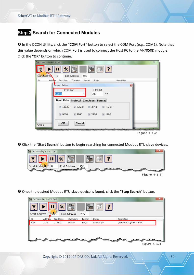
Step 3 Search for Connected Modules In the DCON Utility, click the “COM Port” button to select the COM Port (e.g., COM1). Note that this value depends on which COM Port is used to connect the Host PC to the M-7050D module. Click the “OK” button to continue. Click the “Start Search” button to begin searching for connected Modbus RTU slave devices.
Once the desired Modbus RTU slave device is found, click the “Stop Search” button.
Figure 4-1.2
Figure 4-1.3
Figure 4-1.4

EtherCAT to Modbus RTU Gateway
Copyright © 2019 ICP DAS CO., Ltd. All Rights Reserved. - 35 -
Step 4 Configure the Net ID , Baud Rate and Data Format Click the name of the module in the ID column to open the configuration dialog box. Enter the Address (Net ID), Baud Rate and Data Format information for the Modbus RTU slave device. Click the “Set Module Configurations” button to save the new configuration information.
NOTE If multiple Modbus RTU slave devices are connected to the RS‐485 network, a unique Net ID needs to be assigned to each device.
Figure 4-1.5

EtherCAT to Modbus RTU Gateway
Copyright © 2019 ICP DAS CO., Ltd. All Rights Reserved. - 36 -
4.2 Configuring and Uploading
Step 1 Connect the ECAT-2610 module to the Host PC. Follow the procedure described below to connect the CA-0915 cable from the ECAT-2610 module to the Host PC. Power off the ECAT-2610 module. Connect the COM1 port on the ECAT-2610 module to the COM Port on the Host PC using the CA-0915 cable, as illustrated in the diagram below.
Figure 4-2.1
CA-0915 Cable

EtherCAT to Modbus RTU Gateway
Copyright © 2019 ICP DAS CO., Ltd. All Rights Reserved. - 37 -
Step 2 Download the ECAT-2610_Utl_xxxxxx.zip. The “ECAT-2610_Utl_xxxxxx.zip” can be downloaded from the ICP DAS web site at: http://ftp.icpdas.com/pub/cd/fieldbus_cd/ethercat/slave/ecat-2000/software/ Decompressing the “ECAT-2610_Utl_xxxxxx.zip” and then you can find the “7188ECAT folder”. Copy the 7188ECAT folder to a drive on the PC host (e.g., E :\), the 7188ECAT folder should contain the following:
This folder contains additional configuration and reference files for DI, DO, AD and DA commands, etc. Refer to Appendix A2. “Configuration Files Reference for ECAT-2610” for more details.
This is the application file. Refer to A4-2 “Upload Configuration Data” for more details.
This is the Control file for the 7188ECAT application.
This is the configuration file for the Modbus RTU slave devices. The ECAT-2610 will use this file to communicate with the Modbus RTU slave device.
Using this file to upload the configuration data (commands.txt) to the ECAT-2610 module when it is connected to COM1 on the Host PC. Refer to A4-2 “Upload Configuration Data” for more details.
Using this file to upload the configuration data (commands.txt) to the ECAT-2610 module when it is connected to COM2 on the Host PC. Refer to A4-2 “Upload Configuration Data” for more details.
ECAT-2610 Configuration Tool.exe
Step 3 Launch the ECAT-2610 Configurator.exe. Double-click the “ECAT-2610 Configurator.exe” to open configuration toolkit.
Figure 4-2.2

EtherCAT to Modbus RTU Gateway
Copyright © 2019 ICP DAS CO., Ltd. All Rights Reserved. - 38 -
In the left-hand pane is used to set and upload a configuration file to ECAT-2610 module.
05.Rising_Trigger
Set COM Port on the Host PC
Connect to ECAT-2610
Set Baud Rate and Data Format for slave device
Status column
Upload a configuration file to ECAT-2610
Set a Modbus RTU command
Export/Import configuration file
Exit ECAT-2610 configuration tool
Reset command
ECAT-2610 Communicator configuration windows To gain review to these parameters, the entry must be expanded by clicking ‘+’.
This field will automatically display the Modbus Commands string when the above parameters are configured
Set update mode (HEX) 00: update cyclically ≠00: update at the rising edge of InTxPDO[Addr],
See for more details
Assigned to PDO address of ECAT-2610 Starting from 2
Set special code (HEX), default: 00 (None) Valid values: 01: Power-On value 02: byte-swap 04: word-swap 06: both-swap 08: state change trigger 10: constant output
Figure 4-2.3
Add a Modbus CMD String
Create ESI (.XML) file

EtherCAT to Modbus RTU Gateway
Copyright © 2019 ICP DAS CO., Ltd. All Rights Reserved. - 39 -
In the right-hand pane is used to factory debug operations.
Step 4 Modify COM Port number, Baud Rate and Data Format. Modify COM Port number in the “COM” field that depends on the Host PC COM Port (e.g., COM4) that connects to ECAT-2610. Select the appropriate Baud Rate and Data Format settings from the relevant drop down options. Note that the exact values for these parameters will depend on the Modbus RTU slave device being used, e.g., the M-7050D.
Factory Debug (Please skip and don’t use it)
Figure 4-2.4
Figure 4-2.5

EtherCAT to Modbus RTU Gateway
Copyright © 2019 ICP DAS CO., Ltd. All Rights Reserved. - 40 -
Step 5 Modify the Modbus RTU command and relevant property. Here, the M-7050 module is used as an example, as it provides 7-channel Digital Input and 8-channel Digital Output. Type the Modbus RTU command of write Digital Output channels 0 to 7 (see Figure 4-2.6), as follows: Set the appropriate “Net ID(1-255)”, “Modbus Function”, “Address (0-65535)” and “Length” settings from the relevant field depends on the Modbus RTU device. Set the RxPDO address from the “PDO Address” filed. Set the update mode from the “Update Mode(HEX)” filed. Set the special code from the “CMDX(HEX)” filed. Click the “ADD” button to add the “OUTWORD02” item. Type the Modbus RTU command of Read Digital Input channels 0 to 6 (see Figure 4-2.7), as follows:
Set the appropriate “Net ID(1-255)”, “Modbus Function”, “Address (0-65535)” and “Length” settings from the relevant field depends on the Modbus RTU slave device. Set the TxPDO address from the “PDO Address” filed. Set the update mode from the “Update Mode(HEX)” filed. Set the special code from the “CMDX(HEX)” filed. Click the “ADD” button to add the “INWORD02” item.
Figure 4-2.6
Figure 4-2.7

EtherCAT to Modbus RTU Gateway
Copyright © 2019 ICP DAS CO., Ltd. All Rights Reserved. - 41 -
Step 6 Click the “Connect” to connect the ECAT-2610 module Verify that status column shows “Connect” and “Download” button is unlocked.
Figure 4-2.8

EtherCAT to Modbus RTU Gateway
Copyright © 2019 ICP DAS CO., Ltd. All Rights Reserved. - 42 -
Step 7 Starting upload Click the “Download” button to open the “Download Setting Preview” window. Verify that the configuration data is correct (refer to commands.txt file for more detailed information about configuration data format) and click the “OK” button to continue next step.
The “ECAT-2610 Configurator” dialog box will be displayed asking you to reboot the ECAT-2610 module. Therefore, switch off the power to the ECAT-2610 module and then switch it back on again to reboot the module, and click the “OK” button to continue.
Figure 4-2.9
Figure 4-2.10

EtherCAT to Modbus RTU Gateway
Copyright © 2019 ICP DAS CO., Ltd. All Rights Reserved. - 43 -
The status column will be displayed the progress of the upload.
The “ECAT-2610 Configurator” dialog box is displayed again asking you to reboot the ECAT-2610 module when the upload is successful. Therefore, switch off the power to the ECAT-2610 module and then switch it back on again to reboot the module, and click the “OK” button to complete the upload.
Note: If the upload configuration via ECAT-2610 Configurator.exe is failed, then the manually configuration data file and upload is required to make the module working again, refer to A4. “Manually Configure and upload” for more details.
Figure 4-2.11
Figure 4-2.12

EtherCAT to Modbus RTU Gateway
Copyright © 2019 ICP DAS CO., Ltd. All Rights Reserved. - 44 -
4.2.1 Restore to Factory Defaults Settings
Use the following procedure to reset all parameters to their original factory default settings: Connect the COM1 port on the ECAT-2610 module to the COM Port on the Host PC using the CA-0915 cable, as illustrated in the diagram below. In the 7188ECAT folder, double-click the “ECAT-2610 Configurator.exe” to open configuration toolkit. Note the if the 7188ECAT folder does not exist, refer to Section 4.2 “Configuring and Uploading” for details of how to download the 7188ECAT folder.
CA-0915 Cable
Figure 4-2.13
Figure 4-2.14

EtherCAT to Modbus RTU Gateway
Copyright © 2019 ICP DAS CO., Ltd. All Rights Reserved. - 45 -
Modify COM Port number in the “COM” field that depends on the Host PC COM Port (e.g., COM4) that connects to ECAT-2610. Click the “Connect” button to connect the ECAT-2610 module. Verify that status column shows “Connect” and “Download” button is unlocked. Click the “Download” button to open the “ECAT-2610 Configurator” dialog box asking you to download the default setting, and click the “OK” button to continue.
Figure 4-2.15
Figure 4-2.16

EtherCAT to Modbus RTU Gateway
Copyright © 2019 ICP DAS CO., Ltd. All Rights Reserved. - 46 -
The “ECAT-2610 Configurator” dialog box will be displayed asking you to reboot the ECAT-2610 module. Therefore, switch off the power to the ECAT-2610 module and then switch it back on again to reboot the module, and click the “OK” button to continue. The status column will be displayed the progress of the upload.
The “ECAT-2610 Configurator” dialog box is displayed again asking you to reboot the ECAT-2610 module when the upload is successful. Therefore, switch off the power to the ECAT-2610 module and then switch it back on again to reboot the module, and click the “OK” button to complete the upload.
Figure 4-2.17
Figure 4-2.18
Figure 4-2.19

EtherCAT to Modbus RTU Gateway
Copyright © 2019 ICP DAS CO., Ltd. All Rights Reserved. - 47 -
4.3 Testing the Modbus RTU Slave Before beginning the “Test Modbus RTU Slave” process, the configuration data must be correctly formatted and upload to the ECAT-2610 module. Refer to Section 4.2 “Configuring and Uploading” for more details.
NOTE The testing method used depends on your Modbus RTU slave device. Here, the M-7050D module is used as an example. For other Modbus RTU slave device, refer to the Quick Start Guide or User Manual for that specific Modbus RTU slave device.
Step 1 Connect the Modbus RTU Slave Device. Maintain the network connection status for your ECAT-2610 module. Refer to Section 3.2 “Connecting the Power and the Host PC” for more details. Connect the ECAT-2610 module to a Modbus RTU slave device via the RS-485 bus, e.g., the M-7050D module illustrated in the diagram below. Connect a power supply to the Modbus RTU slave device, e.g., the +10 to +30 VDC power supply used for the M-7050D module illustrated in the diagram below.
Figure 4-3.1
RS-485 Wiring
Power Supply
M-7050D 7-ch DI/8-ch DO
+10 ~+30 VDC

EtherCAT to Modbus RTU Gateway
Copyright © 2019 ICP DAS CO., Ltd. All Rights Reserved. - 48 -
Step 2 Launch the TwinCAT Master software You must first install the EtherCAT Master software (e.g., Beckhoff TwinCAT). In this example, we will use Beckhoff TwinCAT 2.x to configuring and operating the ECAT-2610 module, refer to Section 3.4 “Search Modules” for more details. Automatically scan for connected devices
Switch on the power supply, launch the TwinCAT System Manager in Config mode, and scan for
connected devices (see Figure 4-3.2 below). Acknowledge all dialogs by clicking the OK button, so
that the configuration is operating in “FreeRun” mode.
For more detailed information related to launch the TwinCAT Master Software (e.g., Beckhoff
TwinCAT 2.X). Refer to Section 3.4 “Search Modules” or ECAT-2610 Quick Start for more details.
Scan the device configuration by right-clicking the I/O Devices item in the navigation pane, and the selecting the Scan Devices… option form the menu.
Figure 4-3.2
NOTE The EtherCAT system must be in a safe, de-energized state before the ECAT-2610 module is connected to the EtherCAT network.

EtherCAT to Modbus RTU Gateway
Copyright © 2019 ICP DAS CO., Ltd. All Rights Reserved. - 49 -
Step 3 Configuration via TwinCAT In the left-hand pane of the TwinCAT System Manager, expand on the branch for the EtherCAT Box that you wish to configure (i.e., ECAT-2610 in this case). Expand the entries for both TxPDO and RxPDO and click the relevant Inxx and Outxx items to access the properties window and then configure the state, as described in the procedure below.
Figure 4-3.3

EtherCAT to Modbus RTU Gateway
Copyright © 2019 ICP DAS CO., Ltd. All Rights Reserved. - 50 -
Verify the test results of the DO functions for M-7050D module in the following manner. In the left-hand pane of the TwinCAT System Manager window, click the Out02 item. In the right-hand pane, click the Online tab. Click the Write button to open the “Set Value Dialog” dialog box. In the “Set Value Dialog” dialog box, enter the value “0x00ff” in the “Hex:” field, which enables configuration for all DO channels, and then click the OK button. Check that the LEDs for all DO channels on the M-7050D module are illuminated.
Figure 4-3.4
Figure 4-3.5

EtherCAT to Modbus RTU Gateway
Copyright © 2019 ICP DAS CO., Ltd. All Rights Reserved. - 51 -
5. Modbus RTU Master Setup
NOTE
Before beginning the “Modbus RTU Master Setup” process, ensure that your ECAT-2611 module is operating correctly, refer to Chapter 3 “Getting Started” for more detailed information. Here, the PC to be a Modbus RTU Master for example. For other Modbus RTU Master, refer to the Quick Start Guide or User Manual for that specific Modbus RTU Master.
This chapter provides a simple overview of how to configure the basic settings for an ECAT-2611 module, including the Net ID, the Baud Rate and the Data Format, etc., and how to make Modbus RTU Master communicate with ECAT-2611.
5.1 Configuring and Uploading Step 1 Connect the ECAT-2611 module to the Host PC. Follow the procedure described below to connect the CA-0915 cable from the ECAT-2611 module to the Host PC. Power off the ECAT-2611 module. Connect the COM1 port on the ECAT-2611 module to the COM Port on the Host PC using the CA-0915 cable, as illustrated in the diagram below. Power on the ECAT-2611 module.
CA-0915 Cable
Figure 5-1.1

EtherCAT to Modbus RTU Gateway
Copyright © 2019 ICP DAS CO., Ltd. All Rights Reserved. - 52 -
Step 2 Download the ECAT-2611_Utl_xxxxxx.zip. The “ECAT-2611_Utl_xxxxxx.zip” can be downloaded from the ICP DAS web site at:
http://ftp.icpdas.com/pub/cd/fieldbus_cd/ethercat/slave/ecat-2000/software/ Decompressing the “ECAT-2611_Utl_xxxxxx.zip” and then you can find the “7188ECAT folder”. Copy the 7188ECAT folder to a drive on the PC host (e.g., E :\), the 7188ECAT folder should contain the following:
This is the application file. Refer to A4-2 “Upload Configuration Data” for more details.
This is the Control file for the 7188ECAT application.
This is the configuration file for the Modbus RTU slave devices. The ECAT-2611 will use this file to communicate with the Modbus RTU slave device.
Using this file to upload the configuration data (commands.txt) to the ECAT-2611 module when it is connected to COM1 on the Host PC. Refer to A4-2 “Upload Configuration Data” for more details.
Using this file to upload the configuration data (commands.txt) to the ECAT-2611 module when it is connected to COM2 on the Host PC. Refer to A4-2 “Upload Configuration Data” for more details.
ECAT-2611 Configuration Tool.exe
Step 3 Launch the ECAT-2611 Configurator.exe. Double-click the “ECAT-2611 Configurator.exe” to open configuration toolkit.
Figure 5-1.2

EtherCAT to Modbus RTU Gateway
Copyright © 2019 ICP DAS CO., Ltd. All Rights Reserved. - 53 -
The ECAT-2611 configuration toolkit is used to set and upload a configuration file to ECAT-2611 module.
Step 4 Modify COM Port number, Net ID, Baud Rate and Data Format, etc. Modify COM Port number in the “COM” field that depends on the Host PC COM Port (e.g., COM8) that connects to ECAT-2611, see figure 5-1.4. Select the appropriate Net ID, Baud Rate, Data Format and TxPDO/RxPDO size settings from the field and relevant drop down options, see figure 5-1.4. (e.g., modify the Net ID to 2) The factory default settings of ECAT-2611 as shown in the table below:
COM 1 Data Size (bits) 8 Net ID 1 Stop bits (bits) 1 Baud Rate (bps) 115200 TxPDO size 128 Parity None RxPDO size 128
ECAT-2611 Communicator configuration windows To gain review to these parameters, the entry must be expanded by clicking ‘+’.
Set COM Port on the Host PC
Connect to ECAT-2611
Status column
Upload a configuration file to ECAT-2611
Exit ECAT-2611 configuration tool
Set Net ID, Baud Rate and Data Format for ECAT-2611
Create ESI (.XML) file
Save the new configuration data
Set TxPDO/RxPDO size (Max. 256)
Export/Import configuration file
Figure 5-1.3

EtherCAT to Modbus RTU Gateway
Copyright © 2019 ICP DAS CO., Ltd. All Rights Reserved. - 54 -
Click the “Connect” to connect the ECAT-2611 module. Verify that status column shows “Connect” and “Download” button is unlocked. Step 5 Starting upload
Click the “Download” button to continue next step. The “ECAT-2611 Configurator” dialog box will be displayed asking you to reboot the ECAT-2611 module. Therefore, switch off the power to the ECAT-2611 module and then switch it back on again to reboot the module, and click the “OK” button to continue.
Figure 5-1.5
Figure 5-1.6
Figure 5-1.4

EtherCAT to Modbus RTU Gateway
Copyright © 2019 ICP DAS CO., Ltd. All Rights Reserved. - 55 -
The status column will be displayed the progress of the upload. The “ECAT-2611 Configurator” dialog box is displayed again asking you to reboot the ECAT-2611 module when the upload is successful. Therefore, switch off the power to the ECAT-2611 module and then switch it back on again to reboot the module, and click the “OK” button to complete the upload.
Note: If the upload configuration via ECAT-2611 Configurator.exe is failed, then the manually configuration data file and upload is required to make the module working again, refer to A4. “Manually Configure and upload” for more details.
Figure 5-1.7
Figure 5-1.8

EtherCAT to Modbus RTU Gateway
Copyright © 2019 ICP DAS CO., Ltd. All Rights Reserved. - 56 -
5.2 Connecting the Modbus RTU Master In this example, we use PC as Modbus RTU Master, which will be described in more detail below.
Step 1 Connect the Modbus Master device (e.g., PC) to COM2 (RS-485) on the ECAT-2611.
Step 2 Configure your computer to be a Modbus Master
Install Modbus Master Tools (e.g., Modbus Poll, it is a Modbus Master simulator) on your PC. The
location of the download addresses are shown below:
https://www.modbustools.com/download.html Launch the Modbus Poll.exe program. Click the “Read/Write Definition F8” option from the “Setup” menu to open the “Read/Write Definition” dialog.
Figure 5-2.1
Figure 5-2.2

EtherCAT to Modbus RTU Gateway
Copyright © 2019 ICP DAS CO., Ltd. All Rights Reserved. - 57 -
In the “Read/Write Definition” dialog, set the Slave ID, Function code, Start Address and Quantity,
etc. values depends on your ECAT-2611 module and click the “OK” button.
For example, we use Function 04 to read “20” registers from ECAT-2611 address “2” from Slave ID
“2” every 1000 ms.
Maximum 50
Set Net ID of ECAT-2611
Refer table 5.2-1 to type valid PDO address, e.g., 2 means starting from 2.
Figure 5-2.3
Table 5.2-1: The ECAT-2611 supports function code as show in the table below. Function Code Name Valid Read/Write PDO Address Section 03 (0x03) Read holding registers Readback Multiple TxPDO [02 to FF] 6.3 04 (0x04) Read input registers Read Multiple RxPDO [00 to FF] 6.4 06 (0x06) Write single register Write single TxPDO [02 to FF] 6.6 16 (0x10) Write multiple registers Write Multiple TxPDO [02 to FF] 6.8

EtherCAT to Modbus RTU Gateway
Copyright © 2019 ICP DAS CO., Ltd. All Rights Reserved. - 58 -
Click the “Connect… F3” option from the “Connection” menu to open the “Connection Setup”
dialog.
In the “Connection Setup” dialog, select the “Serial Port” from the “Connection” drop down options and set the appropriate serial port settings from the relevant drop down options, and then click the “OK” button.
Set connection type depends on Modbus Master (e.g., PC) connect to ECAT-2611
Set COM Port number depend on Modbus Master COM Port (e.g., PC, COM7) that connect to ECAT-2611
Set Baud Rate, Data Format and Modbus Protocol depend on ECAT-2611
Figure 5-2.4
Figure 5-2.5

EtherCAT to Modbus RTU Gateway
Copyright © 2019 ICP DAS CO., Ltd. All Rights Reserved. - 59 -
In the “Mbpoll1” window, verify that connection is successful (ERR = 0).
Figure 5-2.6

EtherCAT to Modbus RTU Gateway
Copyright © 2019 ICP DAS CO., Ltd. All Rights Reserved. - 60 -
5.3 Testing the Modbus RTU Master Before beginning the “Test Modbus RTU Master” process, confirm that Sections 5.1 and 5.2 have been completed.
Step 1 Launch the TwinCAT Master software You must first install the EtherCAT Master software (e.g., Beckhoff TwinCAT). In this example, we will use Beckhoff TwinCAT 2.x to configuring and operating the ECAT-2611 module, refer to Section 3.4 “Search Modules” for more details. Automatically scan for connected devices
Switch on the power supply, launch the TwinCAT System Manager in Config mode, and scan for
connected devices (see Figure 5-3.1 below). Acknowledge all dialogs by clicking the OK button, so
that the configuration is operating in “FreeRun” mode.
For more detailed information related to launch the TwinCAT Master Software (e.g., Beckhoff
TwinCAT 2.X). Refer to Section 3.4 “Search Modules” or ECAT-2611 Quick Start for more details.
Scan the device configuration by right-clicking the I/O Devices item in the navigation pane, and the selecting the Scan Devices… option form the menu.
Figure 5-3.1
NOTE The EtherCAT system must be in a safe, de-energized state before the ECAT-2611 module is connected to the EtherCAT network.

EtherCAT to Modbus RTU Gateway
Copyright © 2019 ICP DAS CO., Ltd. All Rights Reserved. - 61 -
Step 2 Configuration via TwinCAT In the left-hand pane of the TwinCAT System Manager, expand on the branch for the EtherCAT Box that you wish to configure (i.e., ECAT-2611 in this case). Expand the entries for both TxPDO and RxPDO and click the relevant Inxx and Outxx items to access the properties window and then configure the state, as described in the procedure below.
Figure 5-3.2

EtherCAT to Modbus RTU Gateway
Copyright © 2019 ICP DAS CO., Ltd. All Rights Reserved. - 62 -
Verify the test results of the function 03 “Read holding registers” in the following manner. In the “Modbus Poll” program, set the function 03 and relevant property, refer to Section 5.2 “Connecting the Modbus RTU Master” for more details. In the left-hand pane of the TwinCAT System Manager window, click the Out02 item. In the right-hand pane, click the Online tab. Click the Write button to open the “Set Value Dialog” dialog. In the “Set Value Dialog” dialog, enter the value “10” in the “Dec:” field and click the OK button. Repeat Steps 2 to 5 above to set the value “10” for Out03 to Out0A items. In the “Modbus Poll” program, verify that the addresses 2 to 10 are shown “10” in the value cell.
Figure 5-3.3
Figure 5-3.4

EtherCAT to Modbus RTU Gateway
Copyright © 2019 ICP DAS CO., Ltd. All Rights Reserved. - 63 -
Verify the test results of the function 16 “Write multiple registers” in the following manner. In the “Modbus Poll” program, set the function 16 and relevant property, as Figure below. Refer to Section 5.2 “Connecting the Modbus RTU Master” for more details. In the “Modbus Poll” program, double-click the value cell of address 2 to open the “Enter signed int 16” dialog. In the “Enter signed int 16” dialog, enter “20” in the “Value” filed and click the OK button.
Figure 5-3.5
Figure 5-3.6

EtherCAT to Modbus RTU Gateway
Copyright © 2019 ICP DAS CO., Ltd. All Rights Reserved. - 64 -
Repeat Steps 2 to 3 above to set the value “20” for addresses 3 to 10. In the left-hand pane of the TwinCAT System Manager window, click the TxPDO 0x00-0x7F item.
In the right-hand pane, check the In02 to In0A items is 0x0014 (20).
Figure 5-3.7
Figure 5-3.8

EtherCAT to Modbus RTU Gateway
Copyright © 2019 ICP DAS CO., Ltd. All Rights Reserved. - 65 -
6. Modbus Information Modbus is a communication protocol that was developed by Modicon in 1979. Detailed information regarding the Modbus protocol can be found at: http://www.modbus.org. The different versions of Modbus used today include Modbus RTU, which is based on serial communication interfaces such as RS-485 and RS-232, as well as Modbus ASCII and Modbus TCP, which uses the Modbus RTU protocol embedded into TCP packets.
Modbus Message Structure Modbus devices communicate using a master-slave (client-server) technique in which only one device (the master/client) can initiate transactions (called queries). The other devices (slaves/servers) respond by supplying the requested data to the master, or by taking the action requested in the query. A query from a master will consist of a slave, or broadcast, address, a function code defining the requested action, any required data, and an error checking field. A response from a slave consists of fields confirming the action taken, any data to be returned, and an error checking field. Modbus RTU Data Structure
Byte 00 Byte 01 Byte 02-03 Byte 04-05
Net ID (Station number)
Function Code Data Field
Reference Number (Address Mapping)
Number of Points
Net ID: Specifies the address of the receiver (i.e., the Modbus RTU slave).
Function Code: Specifies the message type.
Data Field: The data block.

EtherCAT to Modbus RTU Gateway
Copyright © 2019 ICP DAS CO., Ltd. All Rights Reserved. - 66 -
Net ID (Station Number) The first byte in the message structure of a Modbus RTU query is the address of the receiver. A valid address is in the range from 0 to 247. Address 0 is used for broadcast purposes, while addresses 1 to 247 are assigned to individual Modbus devices.
Function Code The second byte in the message structure of a Modbus RTU query is the function code, which describes what the slave device is required to do. Valid function codes range between 1 and 255. To answer the query, the slave device uses the same function code as contained in the request. The highest bit in the function code will only be set to ‘1’ if an error occurs in the system. In this way, the master device will know whether or not the message has been correctly transmitted.
Code Function Reference (Address) 01 (0x01) Read Multiple Coils Status for DO 0xxxx 02 (0x02) Read Multiple Input Discrete for DI 1xxxx 03 (0x03) Read Multiple Registers for AO 4xxxx 04 (0x04) Read Multiple Input Registers for AI 3xxxx 05 (0x05) Write Single Coil for DO 0xxxx 06 (0x06) Write Single Register for AO 4xxxx 15 (0x0F) Force Multiple Coils for DO 0xxxx 16 (0x10) Write Multiple Registers for AO 4xxxx

EtherCAT to Modbus RTU Gateway
Copyright © 2019 ICP DAS CO., Ltd. All Rights Reserved. - 67 -
Data Field Data is transmitted in 8-, 16- and 32-bit format. The data for 16-bit registers is transmitted in high-byte first format. For example: 0x0A0B will be transmitted as 0x0A, 0x0B. The data for 32-bit registers is transmitted as two 16-bit registers, and is low-word first. For example: 0x0A0B0C0D will be transmitted as 0x0C, 0x0D, 0x0A, 0x0B. The data field for messages sent between a master device and a slave device contains additional information about the action to be taken by the master, or any information requested by the slave. If the master does not require this information, the data field can be empty.
Reference (Address) Description
0xxxx Read/Write Discrete Outputs or Coils.
An 0x reference address is used to output device data to a Digital Output channel.
1xxxx Read Discrete Inputs.
The ON/OFF status of a 1x reference address is controlled by the corresponding Digital Input channel.
3xxxx Read Input Registers.
A 3x reference register contains a 16-bit value received from an external source, e.g. an analog signal.
4xxxx Read/Write Output or Holding Registers.
A 4x register is used to store 16bits of numerical data (binary or decimal), or to send data from the CPU to an output channel.
NOTE
The details regarding the address mapping (Reference Number) depends on which Modbus RTU slave device in installed.

EtherCAT to Modbus RTU Gateway
Copyright © 2019 ICP DAS CO., Ltd. All Rights Reserved. - 68 -
FC1(0x01) Read Multiple Coils (0xxxx) for DO
This function code is used to read either the current status of the coils or the current Digital Output readback value. [Request]
Byte Description Size Value 00 Net ID (Station Number) 1 Byte 1 to 247 01 Function Code 1 Byte 0x01
02-03 Starting DO Address 2 Bytes
Depends on the Modbus address of the slave device. Byte 02 = high byte Byte 03 = low byte
04-05 Number of Points (Channels) 2 Bytes Byte 04 = high byte Byte 05 = low byte
[Response] Byte Description Size Value 00 Net ID (Station Number) 1 Byte 1 to 247 01 Function Code 1 Byte 0x01
02 Byte Count 1 Byte Byte Count of the Response ( n = (Points+7)/8 )
03 Data n Bytes
n= 1; Byte 03 = data bit 7 to 0 n= 2; Byte 04 = data bit 15 to 8 ....... n= m; Byte m+2 = data bit (8m-1) to 8(m-1)
[Error Response] Byte Description Size Value 00 Net ID (Station Number) 1 Byte 1 to 247 01 Function Code 1 Byte 0x81
02 Exception Code 1 Byte Refer to the Modbus Standard Specifications for more details

EtherCAT to Modbus RTU Gateway
Copyright © 2019 ICP DAS CO., Ltd. All Rights Reserved. - 69 -
FC2(0x02) Read Multiple Input Discrete (1xxxx) for DI
This function code is used to read the current Digital Input value. [Request]
Byte Description Size Value 00 Net ID (Station Number) 1 Byte 1 to 247 01 Function Code 1 Byte 0x02
02-03 Starting DI Address 2 Bytes
Depends on the Modbus address of the slave device. Byte 02 = high byte Byte 03 = low byte
04-05 Number of Points (Channels) 2 Bytes Byte 04 = high byte Byte 05 = low byte
[Response]
Byte Description Size Value 00 Net ID (Station Number) 1 Byte 1 to 247 01 Function Code 1 Byte 0x02
02 Byte Count 1 Byte Byte Count of Response ( n =(Points+7)/8 )
03 Data n Bytes
n= 1; Byte 03 = data bit 7 to 0 n= 2; Byte 04 = data bit 15 to 8 ....... n= m; Byte m+2 = data bit (8m-1) to 8(m-1)
[Error Response]
Byte Description Size Value 00 Net ID (Station Number) 1 Byte 1 to 247 01 Function Code 1 Byte 0x82
02 Exception Code 1 Byte Refer to the Modbus Standard Specifications for more details

EtherCAT to Modbus RTU Gateway
Copyright © 2019 ICP DAS CO., Ltd. All Rights Reserved. - 70 -
FC3(0x03) Read Multiple Registers (4xxxx) for AO
This function code is used to readback either the current values in the holding registers or the Analog Output value. [Request]
Byte Description Size Value 00 Net ID (Station Number) 1 Byte 1 to 247 01 Function Code 1 Byte 0x03
02-03 Starting AO Address 2 Bytes
Depends on the Modbus address of the slave device. Byte 02 = high byte Byte 03 = low byte
04-05 Number of 16-bit Registers (Channels)
2 Bytes Word Count Byte 04 = high byte Byte 05 = low byte
[Response]
Byte Description Size Value 00 Net ID (Station Number) 1 Byte 1 to 247
01 Function Code 1 Byte 0x03
02 Byte Count 1 Byte Byte Count of the Response (n=Points x 2 Bytes)
03~ Register Values n Bytes
Register Values n= 2; Byte 03 = high byte
Byte 04 = low byte .......
n= m; Byte 03 = high byte Byte 04 = low byte ....... Byte m+1 = high byte Byte m+2 = low byte
[Error Response]
Byte Description Size Value 00 Net ID (Station Number) 1 Byte 1 to 247 01 Function Code 1 Byte 0x83
02 Exception Code 1 Byte Refer to the Modbus Standard Specifications for more details

EtherCAT to Modbus RTU Gateway
Copyright © 2019 ICP DAS CO., Ltd. All Rights Reserved. - 71 -
FC4(0x04) Read Multiple Input Registers (3xxxx) for AI
This function code is used to read either the input registers or the current Analog Input value. [Request]
Byte Description Size Value 00 Net ID (Station Number) 1 Byte 1 to 247 01 Function Code 1 Byte 0x04
02-03 Starting AI Address 2 Bytes
Depends on the Modbus address of the slave device. Byte 02 = high byte Byte 03 = low byte
04-05 Number of 16-bit Registers (Channels)
2 Bytes Word Count Byte 04 = high byte Byte 05 = low byte
[Response]
Byte Description Size Value 00 Net ID (Station Number) 1 Byte 1 to 247 01 Function Code 1 Byte 0x04 02 Byte Count 1 Byte Byte Count of the Response (n=Points x 2 Bytes)
03~ Register Values n Bytes
Register Values n= 2; Byte 03 = high byte
Byte 04 = low byte .......
n= m; Byte 03 = high byte Byte 04 = low byte ....... Byte m+1 = high byte
Byte m+2 = low byte [Error Response]
Byte Description Size Value 00 Net ID (Station Number) 1 Byte 1 to 247 01 Function Code 1 Byte 0x84
02 Exception Code 1 Byte Refer to the Modbus Standard Specifications for more details.

EtherCAT to Modbus RTU Gateway
Copyright © 2019 ICP DAS CO., Ltd. All Rights Reserved. - 72 -
FC5(0x05) Write Single Coil (0xxxx) for DO
This function code is used to set the status of a single coil or a single Digital Output value. [Request]
Byte Description Size Value 00 Net ID (Station Number) 1 Byte 1 to 247 01 Function Code 1 Byte 0x05
02-03 DO Address 2 Bytes
Depends on the Modbus address of the slave device. Byte 02 = high byte Byte 03 = low byte
04-05 Output Value 2 Bytes
0xFF 00 sets the output to ON. 0x00 00 sets the output to OFF. All other values are invalid and will not affect the coil. Byte 04 = high byte Byte 05 = low byte
[Response]
Byte Description Size Value 00 Net ID (Station Number) 1 Byte 1 to 247 01 Function Code 1 Byte 0x05
02-03 DO Address 2 Bytes The value is the same as Bytes 02-03 of the Request
04-05 Output Value 2 Bytes The value is the same as Bytes 04-05 of the Request
[Error Response]
Byte Description Size Value 00 Net ID (Station Number) 1 Byte 1 to 247 01 Function Code 1 Byte 0x85
02 Exception Code 1 Byte Refer to the Modbus Standard Specifications for more details.

EtherCAT to Modbus RTU Gateway
Copyright © 2019 ICP DAS CO., Ltd. All Rights Reserved. - 73 -
FC6(0x06) Write Single Register (4xxxx) for AO
This function code is used to set a specific holding register to store the configuration values. [Request]
Byte Description Size Value 00 Net ID (Station Number) 1 Byte 1 to 247 01 Function Code 1 Byte 0x06
02-03 AO Address 2 Bytes
Depends on the Modbus address of the slave device. Byte 02 = high byte Byte 03 = low byte
04-05 Register Value 2 Bytes Register Value Byte 04 = high byte Byte 05 = low byte
[Response]
Byte Description Size Value 00 Net ID (Station Number) 1 Byte 1 to 247 01 Function Code 1 Byte 0x06
02-03 AO Address 2 Bytes The value is the same as Bytes 02-03 of the Request
04-05 Register Value 2 Bytes The value is the same as Bytes 04-05 of the Request
[Error Response]
Byte Description Size Value 00 Net ID (Station Number) 1 Byte 1 to 247 01 Function Code 1 Byte 0x86
02 Exception Code 1 Byte Refer to the Modbus Standard Specifications for more details.

EtherCAT to Modbus RTU Gateway
Copyright © 2019 ICP DAS CO., Ltd. All Rights Reserved. - 74 -
FC15(0x0F) Force Multiple Coils (0xxxx) for DO
This function code is used to set the status of multiple coils or to write multiple Digital Output values. [Request]
Byte Description Size Value 00 Net ID (Station Number) 1 Byte 1 to 247 01 Function Code 1 Byte 0x0F
02-03 Starting DO Address 2 Bytes
Depends on the Modbus address of the slave device. Byte 02 = high byte Byte 03 = low byte
04-05 Number of Output Channels (Points)
2 Bytes Byte 04 = high byte Byte 05 = low byte
06 Byte count 1 Byte n = (Points +7)/8
07 Output value n Bytes
A bit corresponds to a channel. A value of 1 for a bit denotes that the channel is ON, while a value of denotes that the channel is OFF. n= 1; Byte 07 = data bit 7 to 0 n= 2; Byte 08 = data bit 15 to 8 ....... n= m; Byte m+6 = data bit (8m-1)to 8 (m-1)
[Response]
Byte Description Size Value 00 Net ID (Station Number) 1 Byte 1 to 247 01 Function Code 1 Byte 0x0F
02-03 Starting DO Address 2 Bytes The value is the same as Bytes 02-03 of the Request
04-05 Number of Output Channels (Points)
2 Bytes The value is the same as Bytes 04-05 of the Request
[Error Response]
Byte Description Size Value 00 Net ID (Station Number) 1 Byte 1to 247 01 Function Code 1 Byte 0x8F
02 Exception Code 1 Byte Refer to the Modbus Standard Specifications for more details.

EtherCAT to Modbus RTU Gateway
Copyright © 2019 ICP DAS CO., Ltd. All Rights Reserved. - 75 -
FC16(0x10) Write Multiple Registers (4xxxx) for AO
This function code is used to set multiple holding registers that are used to store the configuration values. [Request]
Byte Description Size Value 00 Net ID (Station Number) 1 Byte 1 to 247 01 Function Code 1 Byte 0x10
02-03 Starting AO Address 2 Bytes
Depends on the Modbus address of the slave device. Byte 02 = high byte Byte 03 = low byte
04-05 Number of 16-bit Registers (Channels) 2 Bytes
Word Count. Byte 04 = high byte Byte 05 = low byte
06 Byte Count 1 Byte n =Points x 2 Bytes
07 Register Values n Bytes
Register Values. n= 2; Byte 03 = high byte
Byte 04 = low byte .......
n= m; Byte 03 = high byte Byte 04 = low byte .......
Byte m+1 = high byte Byte m+2 = low byte
[Response]
Byte Description Size Value 00 Net ID (Station Number) 1 Byte 1 to 247 01 Function Code 1 Byte 0x10
02-03 Starting AO Address 2 Bytes The value is the same as Bytes 02-03 of the Request
04-05 Number of 16-bit Registers (Channels) 2 Bytes The value is the same as Bytes 04-05 of the
Request [Error Response]
Byte Description Size Value 00 Net ID (Station Number) 1 Byte 1 to 247 01 Function Code 1 Byte 0x90
02 Exception Code 1 Byte Refer to the Modbus Standard Specifications for more details.

EtherCAT to Modbus RTU Gateway
Copyright © 2019 ICP DAS CO., Ltd. All Rights Reserved. - 76 -
FC255(0xFF) Special Commands
This function code is special command that applies only to the ECAT-2610 module.
Commands Description Reference
FF 03 00 00 00 02 Read system status (2610Sys0 + 2610Sys1)
Refer to Section 3.5.1 “Module Status and Error Mode” for more details.
FF 03 00 01 00 01 Save the RS-485 cycle time, unit = 0.1 ms Refer to 16. RS485_Cycle_Time for more details.
FF 06 00 00 00 nn Delay 100 ms x nn Refer to 11.Delay_Command for more details. FF 06 00 01 00 nn Delay 1 ms x nn

EtherCAT to Modbus RTU Gateway
Copyright © 2019 ICP DAS CO., Ltd. All Rights Reserved. - 77 -
7. Upload Commands.txt Operations If the ECAT-2610(-DW)/2611 module is not functioning correctly, e.g., if there is no response from the module, or if the LED is continuously displayed as either ON or OFF, you can use Debug Mode to diagnose the problem. To begin, short the TxD and RxD pins on the module, as illustrated in Figure 7-1.1, the ECAT-2610(-DW)/2611 module will then enter the “Init” (Debug Mode). In the Debug Mode, the module will bypass the EEPROM and stop executing commands, and then you can erase the EEPROM and upload new configuration data file (commands.txt) to the EEPROM, as described below:
Step 1 Switch to Init Mode Follow the procedure described below to switch the ECAT-2610(-DW)/2611 module to Init mode. Power off the ECAT-2610(-DW)/2611 module. Connect the COM1 (Console Port) on the ECAT-2610(-DW)/2611 module to the COM Port on the Host PC using the CA-0915 cable, as illustrated in the diagram below.
Connect the TxD pin to RxD pin on the COM3 terminal block on the ECAT-2610(-DW)/2611
module, as illustrated in the diagram below.
Short the TxD and RxD pins
Figure 7.1.1
CA-0915 Cable

EtherCAT to Modbus RTU Gateway
Copyright © 2019 ICP DAS CO., Ltd. All Rights Reserved. - 78 -
Step 2 Launch the Configuration/Diagnostic Utility (7188ECAT.exe)
Here, the Windows XP is used as an example, type “cmd” in the Open field and the press Enter to
open the Command Prompt window.
In the Command Prompt window, type “e:” (7188ECAT folder location on your hard drive) and then press Enter. Type cd 7188ecat and then press Enter. Type execcom4 and then press Enter to automatically launch the 7188ECAT.exe Configuration/Diagnostic Utility. Note that the execcom4 is used COM Port 4 on the Host PC to download data, refer to Figure A4-17” for more details.
Figure 7-1.3
Figure 7-1.2
NOTE Open a Command Prompt window method depends on the version of Windows being used.

EtherCAT to Modbus RTU Gateway
Copyright © 2019 ICP DAS CO., Ltd. All Rights Reserved. - 79 -
Step 3 Power on the ECAT-2610(-DW)/2611 module in Init Mode When you power on the ECAT-2610(-DW)/2611 module, it will automatically enter the “INIT” (Debug Mode), as illustrated in the diagram below.
There are ten commands applicable to uploading and diagnostic operations, as described
below:
Command Description Operations CTRL+F4 Upload the commands.txt file to the EEPROM Upload READ1 Read data from the EEPROM Factory Debug READ2 Read data from the EEPROM Factory Debug SHOW0 Show the Version Number Factory Debug SHOW1 Show the status Factory Debug SHOW2 Show InTxPDO[00] to InTxPDO[FF] Factory Debug SHOW3 Show OutRxPDO[00] to OutRxPDO[FF] Factory Debug SHOW4 Show the Debug Information Factory Debug SHOW5 Show the Debug Information Step by Step (Slow Speed) Factory Debug ERASE Erase all data from the EEPROM Upload Only the CTRL+F4 and ERASE commands are applicable to uploading new configuration file (commands.txt) to the EEPROM. The other commands are applicable for factory debug operations. \
NOTE The EEPROM is designed to store data that is not changed frequently. It is not suitable for frequent access a large amount of data, and the erase/write cycle is limited, so it should not be changed frequently when testing that it will easily cause damage to the module.
Figure 7-1.4
INIT Mode

EtherCAT to Modbus RTU Gateway
Copyright © 2019 ICP DAS CO., Ltd. All Rights Reserved. - 80 -
Step 4 Disconnect the TxD and RxD pins
Step 5 Upload the new configuration file to the EEPROM Since the configuration has been changed, the new configuration data must be uploaded to the EEPROM using the Configuration/Diagnostic Utility. To do this, follow the procedure described below. Type erase in the Command Prompt window and then press Enter to erase all currently existing data from the EEPROM.
Switch off the power to the ECAT-2610(-DW)/2611 module and then switch it back on again to reboot the module.
Open the TxD and RxD pins
Figure 7-1.5
Type erase and then press Enter
Figure 7-1.6
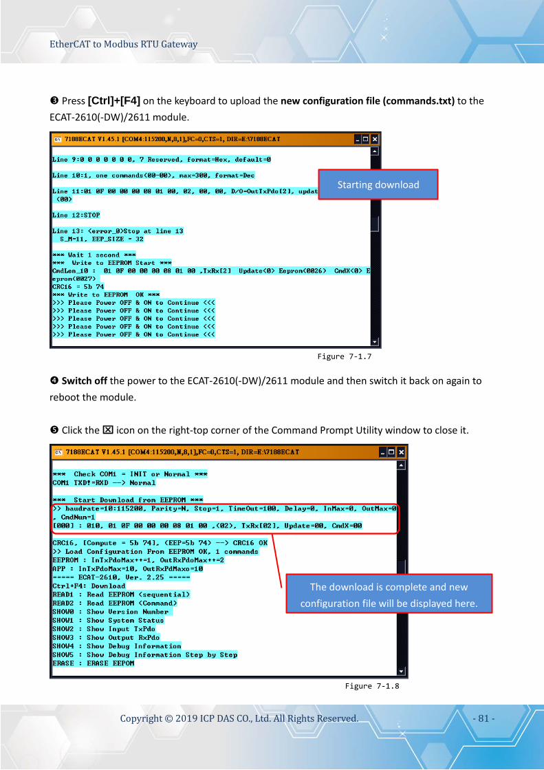
EtherCAT to Modbus RTU Gateway
Copyright © 2019 ICP DAS CO., Ltd. All Rights Reserved. - 81 -
Press [Ctrl]+[F4] on the keyboard to upload the new configuration file (commands.txt) to the ECAT-2610(-DW)/2611 module.
Switch off the power to the ECAT-2610(-DW)/2611 module and then switch it back on again to reboot the module. Click the icon on the right-top corner of the Command Prompt Utility window to close it.
Figure 7-1.7
Starting download
The download is complete and new configuration file will be displayed here.
Figure 7-1.8

EtherCAT to Modbus RTU Gateway
Copyright © 2019 ICP DAS CO., Ltd. All Rights Reserved. - 82 -
8. Distributed Clocks (for ECAT-2610) The term “Distributed Clocks” (DC) refers to a logical network of synchronized, distributed local clocks in an EtherCAT fieldbus system. By using distributed clocks, EtherCAT, the real-time Ethernet protocol, is able to synchronize the time in all local bus devices within a very narrow tolerance range. Additional and more detailed information about EtherCAT in general and Distributed Clocks in particular, can be found at http://www.ethercat.org/.
8.1 Modbus RTU Timing In this example, we use the ECAT-2610 module to control an M-7050 module (Modbus RTU I/O device), the 7-channel Digital Input and 8-channel Digital Output of ICP DAS. The following four example for measure the hardware timing for send command, read response and DC cycle time, as described below:
Sending a single Modbus Command, i.e., Write DO Use the DCON Utility to easily and quickly get the correct Write DO command and read response data. Refer to A1 “How do I retrieve the Modbus command via DCON Utility” for details of how to send commands to an M-7050 module as described below:
Figure 8-1.1
1. Select Baud Rate 2. Select Modbus RTU 3. Select Module 4. Select Command 5. Click “Send” button Send Write DO Command String = 01 0F 00 00 00 08 01 00 FE 95 Receive Response String = 01 0F 00 00 00 08 54 0D NOTE: The FE 95 and 54 0D items are check sum bytes.

EtherCAT to Modbus RTU Gateway
Copyright © 2019 ICP DAS CO., Ltd. All Rights Reserved. - 83 -
Edit the configuration data (commands.txt) by modifying the relevant information, including the Baud Rate, Data Format and Write DO command (Paste the command obtained in Step1), refer to Section 4.2 “Configuring and Uploading” or A4. “Manually configure and Upload” for details of how to upload the configuration data (see Figure 8-1.2) to the ECAT-2610 module.
The ECAT-2610 module will first send the Write DO command 01 0F 00 00 00 08 01 00 FE 95 to the M-7050 module, then read the response 01 0F 00 00 00 08 54 0D from the M-7050 module. The send_ then_read operation will not stop and will continue to repeat in sequence. Measure hardware timing result for a single send Write DO command/read response cycle is as follows: To Send the command 01 0F 00 00 00 08 01 00 FE 95 take approximately 1 ms. To Read the response 01 0F 00 00 00 08 54 take approximately 1 ms. The send_then_read process takes approximately 5 ms The read_N to send_N+1 process takes approximately 2 ms A single send_read_cycle is approximately 5+2=7 ms
Figure 8-1.3
Figure 8-1.2

EtherCAT to Modbus RTU Gateway
Copyright © 2019 ICP DAS CO., Ltd. All Rights Reserved. - 84 -
Sending a single Modbus Command, i.e., Read DI Back to DCON Utility to easily and quickly get the correct Read DI command and read response data. Refer to A1 “How do I retrieve the Modbus command via DCON Utility” for details of how to send commands to an M-7050 module as described below:
Edit the configuration data (commands.txt) by modifying the relevant information, including the Baud Rate, Data Format and Read DI command (Paste the command obtained in Step1) , refer to Section 4.2 “Configuring and Uploading” or A4. “Manually configure and Upload” for details of how to upload the configuration data (see Figure 8-1.5) to the ECAT-2610 module.
Figure 8-1.4
Figure 8-1.5
Send Read DI command string = 01 02 00 00 00 07 39 C8 Receive response string = 01 02 01 00 A1 88 NOTE: The 39 C8 and A1 88 items are check sum bytes.

EtherCAT to Modbus RTU Gateway
Copyright © 2019 ICP DAS CO., Ltd. All Rights Reserved. - 85 -
The ECAT-2610 will first send the Read DI command 01 02 00 00 00 07 39 C8 to the M-7050, then read the response 01 02 01 00 A1 88 from the M-7050 module. The send_ then_read operation will not stop and will continue to repeat in sequence. Measure hardware timing result for a single send Read DI command/read response cycle is as follows: To Send the command 01 02 00 00 00 07 39 C8 takes approximately 0.8 ms To Read the response 01 02 01 00 A1 88 takes approximately 0.7 ms The send_then_read process takes approximately 4 ms The read_N to send_N+1 process takes approximately 2 ms A single send_read_cycle takes approximately 4+2=6 ms
Figure 8-1.6
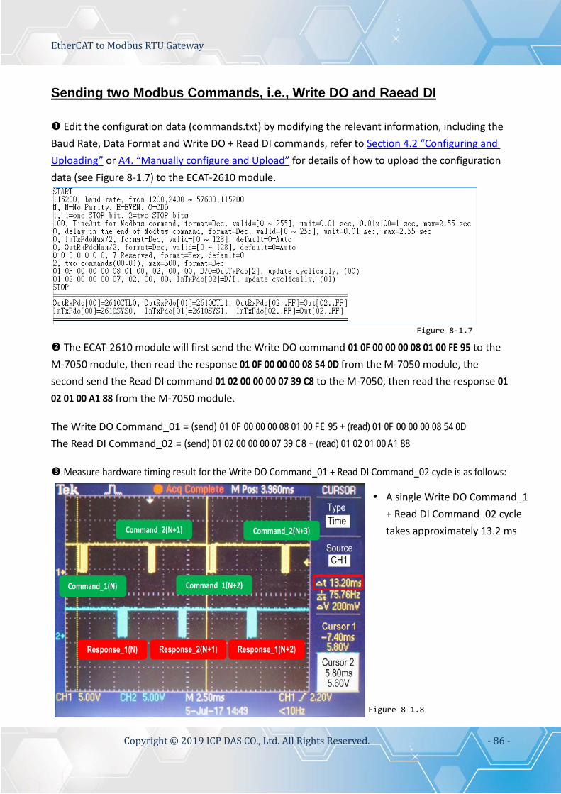
EtherCAT to Modbus RTU Gateway
Copyright © 2019 ICP DAS CO., Ltd. All Rights Reserved. - 86 -
Sending two Modbus Commands, i.e., Write DO and Raead DI Edit the configuration data (commands.txt) by modifying the relevant information, including the Baud Rate, Data Format and Write DO + Read DI commands, refer to Section 4.2 “Configuring and Uploading” or A4. “Manually configure and Upload” for details of how to upload the configuration data (see Figure 8-1.7) to the ECAT-2610 module.
The ECAT-2610 module will first send the Write DO command 01 0F 00 00 00 08 01 00 FE 95 to the M-7050 module, then read the response 01 0F 00 00 00 08 54 0D from the M-7050 module, the second send the Read DI command 01 02 00 00 00 07 39 C8 to the M-7050, then read the response 01 02 01 00 A1 88 from the M-7050 module. The Write DO Command_01 = (send) 01 0F 00 00 00 08 01 00 FE 95 + (read) 01 0F 00 00 00 08 54 0D The Read DI Command_02 = (send) 01 02 00 00 00 07 39 C8 + (read) 01 02 01 00 A1 88 Measure hardware timing result for the Write DO Command_01 + Read DI Command_02 cycle is as follows:
Figure 8-1.8
Figure 8-1.7
A single Write DO Command_1 + Read DI Command_02 cycle takes approximately 13.2 ms

EtherCAT to Modbus RTU Gateway
Copyright © 2019 ICP DAS CO., Ltd. All Rights Reserved. - 87 -
DC Cycle Time The ECAT-2610 module will automatically detect and synchronize to the DC signal each time the first command is executed. The cycle time for the Write DO command is about 7 ms, and the cycle time for the Write DO + Read DI commands is about 13.2 ms. If the DC signal is set to 20 ms, the cycle time for the Write DO command will be as follows:
If the DC signal is set to 20 ms, the cycle time for the Write DO + Read DI commands will be as
illustrated in the following diagram:
Sync to DC at every first command
Figure 8-1.9
Sync to DC at every first command
Figure 8-1.10
A single command_1 + command_02 cycle takes approximately 13.2ms. If the DC Cycle Time is set to 10 ms < 13.2 ms, the ECAT-2610 will synchronize to the DC at every first command. So the timing diagram for when the DC=10 ms is as same as for when the DC=20 ms and above. The total command cycle time can be greater than the DC Cycle Time without causing any significant problems.

EtherCAT to Modbus RTU Gateway
Copyright © 2019 ICP DAS CO., Ltd. All Rights Reserved. - 88 -
8.2 DC Configuration and Operation This Section provides a simple overview of how to configure the Distributed Clocks (DC), follow the procedure described below. The image below shows an example of the setup for Distributed Clocks (DC) test: DC is active DI = ECAT-2052 DO1=M-7055 slave1, DO2=M-7055 slave2 DO1=DI, DO2=DI
Figure 8-2.1: The setup for a Distributed Clocks (DC) test

EtherCAT to Modbus RTU Gateway
Copyright © 2019 ICP DAS CO., Ltd. All Rights Reserved. - 89 -
Launch the TwinCAT3.0 application and then follow the procedure described below to set the Distributed Clocks (DC) operation:
Step 1 Scan for devices
Step 2 Configure the DC mode settings for the ECAT-2610 module
Scan the configuration by first expanding the I/O entry in the left-hand pane of the TwinCAT System Manager and then right-clicking the Devices item. Select the Scan option from the menu to access the configuration panel.
In the left-hand pane click the Box1 and Box2 [ECAT-2610]
In the right-hand pane click the DC tab, and then select the DC-Synchron Option from the operation Mode drop-down menu.
Figure 8-2.2
Figure 8-2.3

EtherCAT to Modbus RTU Gateway
Copyright © 2019 ICP DAS CO., Ltd. All Rights Reserved. - 90 -
Step 3 Activate the PLC
Activate the PLC by right-clicking the PLC item in the left-hand pane of the TwinCAT system Manager and then selecting the Add New Item… option from the menu to open the Add New Item dialog.
In the Add New Item dialog, enter a name for the project in the Name field (e.g., Task1), and then click the Add button. The new item will then be listed in the left-hand pane of the TwinCAT System Manager application.
Right-click the Task1 item in the left-hand pane of the TwinCAT System Manager and then select the Activate Boot Project… item from the menu.
Figure 8-2.4
Figure 8-2.5
Figure 8-2.6

EtherCAT to Modbus RTU Gateway
Copyright © 2019 ICP DAS CO., Ltd. All Rights Reserved. - 91 -
Step 4 Map the M-7055 Output Variables
Step 5 Cycle time settings
To configure the Cycle Time settings, first expand the Tasks item in the left-hand panel of the TwinCAT System and click the PlcTask item. In the Properties window for the PLC Task, click the Task tab, and then set the Cycle Time parameter to 10 ms.
Figure 8-2.7
Figure 8-2.8
Expand the PLC Task Outputs item in the left-hand panel of the TwinCAT System Manager and then double click the entry for MAIN.M7055_DO_SLAVE1_0 to open the Attach Variable dialog box. Expand the Devices item in the Attach Variable dialog box and select the Out000 item from the Box1 [ECAT-2610] list. Click the OK button to continue.

EtherCAT to Modbus RTU Gateway
Copyright © 2019 ICP DAS CO., Ltd. All Rights Reserved. - 92 -
Step 6 Run the PLC
Click the OK button to restart the TwinCAT System in Run Mode.
Click the Activate Configuration button to run the PLC.
Figure 8-2.9
Figure 8-2.11
Click the OK button to activate the new configuration.
Figure 8-2.10

EtherCAT to Modbus RTU Gateway
Copyright © 2019 ICP DAS CO., Ltd. All Rights Reserved. - 93 -
Once the TwinCAT System has restarted, click the Login button.
Click the Start button to start the PLC operation.
Figure 8-2.12
Figure 8-2.13

EtherCAT to Modbus RTU Gateway
Copyright © 2019 ICP DAS CO., Ltd. All Rights Reserved. - 94 -
If the DC-Synchrony option has been set to disabled, the DO1 and DO2 channels will operate independently, below are some examples of the typical timing diagram is about some ms: DO1 to DO2 = 2 ms
DO1 to DO2 = 5 ms
The worst case for DO1 to DO2 is about 7 ms, refer to Section 8.1 “Modbus RTU Timing” for more
information.
Figure 8-2.14
Figure 8-2.15
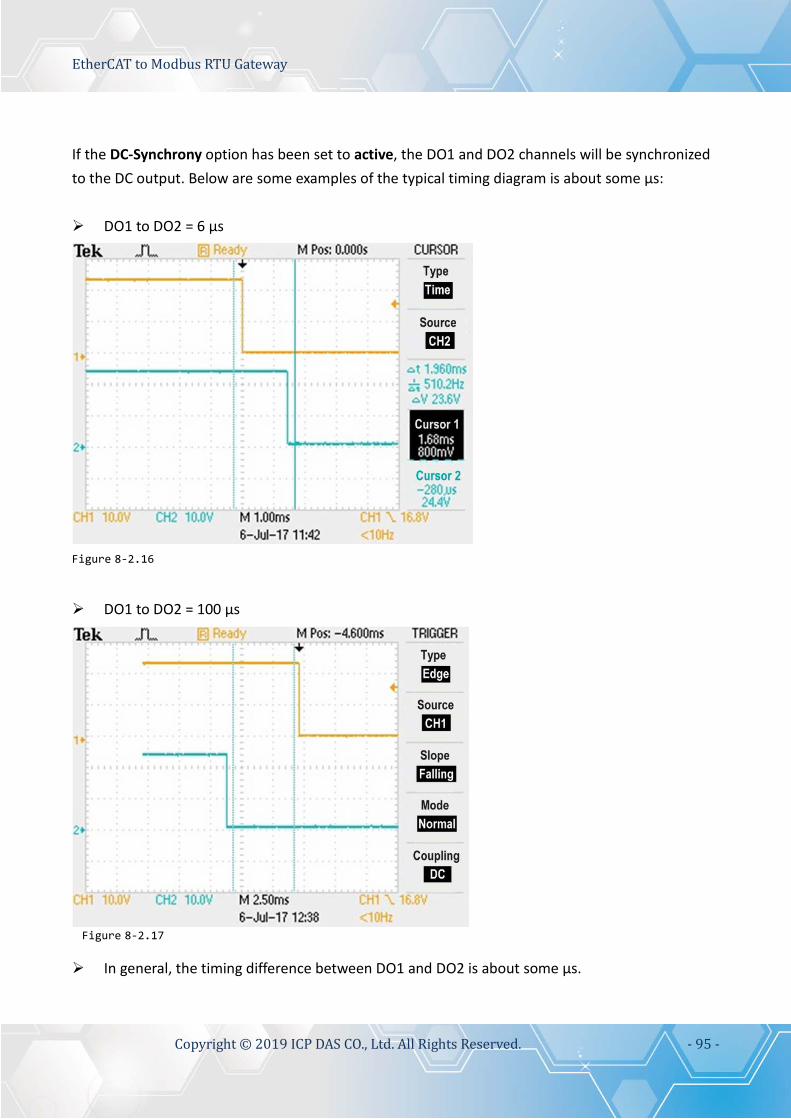
EtherCAT to Modbus RTU Gateway
Copyright © 2019 ICP DAS CO., Ltd. All Rights Reserved. - 95 -
If the DC-Synchrony option has been set to active, the DO1 and DO2 channels will be synchronized to the DC output. Below are some examples of the typical timing diagram is about some μs: DO1 to DO2 = 6 μs
DO1 to DO2 = 100 μs
In general, the timing difference between DO1 and DO2 is about some μs.
Figure 8-2.16
Figure 8-2.17

EtherCAT to Modbus RTU Gateway
Copyright © 2019 ICP DAS CO., Ltd. All Rights Reserved. - 96 -
9. Object Description and Parameterization
The following is a summary of the standard and specific objects that can be used with the ECAT-2610/2611.
9.1 Standard Objects
Index Name Sub- Index Definition Data
Type Flags Notes
1000h Device type 00h Device type UINT32 RO 0x0000 0192(No profile) 1001 h Error Register 00h Error Register UINT16 RO 0x00 1008h Device name 00h ECAT-2610/2611
Communicator Visible String
RO -
1009h Hardware Version 00h Hardware Version UINT16 RO -
100Ah Software Version 00h Software Version UINT16 RO -
1018h Identity object 00h Number of Entries UINT16 RO 04h 01h Vendor ID UINT32 RO - 02h Product Code UINT32 RO - 03h Revision Number UINT32 RO - 04h Serial Number UINT32 RO -
1600h 1601h
Receive PDO mapping
00h RxPDO 0x00-0x7F UINT16 RO Refer to Table 8-1 below 00h RxPDO 0x80-0xFF UINT16 RO
1A00h 1A01h
Transmit PDO mapping
00h TxPDO 0x00-0x7F UINT16 RO Refer to Table 8-1 below 00h TxPDO 0x80-0xFF UINT16 RO
1C00h Sync Manager Communication Type
00h Sync Manger Type UINT16 RO 04h 01h Write to Mailbox UINT16 RO 01h 02h Read from Mailbox UINT16 RO 02h 03h Process Data Out UINT16 RO 03h 04h Process Data In UINT16 RO 04h
1C12h Sync Manager Rx PDO Assign
00h SyncManager 2 Assignment UINT16 RO No. of assigned RxPDO(0-1) 01h Assigned RxPDO UINT16 RO Assigned to RxPDO 1600h
02h Assigned RxPDO UINT16 RO Assigned to RxPDO 1601h 1C13h Sync Manager Tx
PDO Assign 00h SyncManager 3 Assignment UINT16 RO No. of assigned TxPDO(0-1) 01h Assigned TxPDO UINT16 RO Assigned to TxPDO 1A00h
02h Assigned TxPDO UINT16 RO Assigned to TxPDO 1A01h Table 8-1: The PDO mapping for the ECAT-2610/2611 module is static and is as follows: PDO Corresponding Object Internal Memory TxPDO 1A00h Index 2000h, sub-index 1 to 128 Input Data, bytes 0 to 127 TxPDO 1A01h Index 2010h, sub-index 1 to 128 Input Data, bytes 128 to 255 RxPDO 1600h Index 2100h, sub-index 1 to 128 Output Data, bytes 0 to 127 RxPDO 1601h Index 2110h, sub-index 1 to 128 Output Data, bytes 128 to 255

EtherCAT to Modbus RTU Gateway
Copyright © 2019 ICP DAS CO., Ltd. All Rights Reserved. - 97 -
9.2 Specific Objects
Input Buffer
Index Object Name Sub-Index Definition Data Type Flags 2000h Inputs 00h No. of Entries UINT16 RO
01h Input Byte 0000 UINT16 RO 02h Input Byte 0001 UINT16 RO --- --- --- ---
80h Input Byte 0127 UINT16 RO 2010h Inputs 00h No. of Entries UINT16 RO
01h Input Byte 0128 UINT16 RO 02h Input Byte 0129 UINT16 RO --- --- --- ---
80h Input Byte 0255 UINT16 RO
NOTE
The Gateway will only create the actual number of objects needed to store the configuration information for the sub-network.
Output Buffer
Index Object Name Sub-Index Definition Data Type Flags 2100h Outputs 00h No. of Entries UINT16 RO
01h Output Byte 0000 UINT16 R(W) 02h Output Byte 0001 UINT16 R(W) --- --- --- ---
80h Output Byte 0127 UINT16 R(W) 2110h Outputs 00h No. of Entries UINT16 RO
01h Output Byte 0128 UINT16 R(W) 02h Output Byte 0129 UINT16 R(W) --- --- --- ---
80h Output Byte 0255 UINT16 R(W)
NOTES 1: For consistency, any data declared as I/O data will be designated as read-only. 2: The Gateway will only create the actual number of objects needed to store the configuration information for the sub-network.

EtherCAT to Modbus RTU Gateway
Copyright © 2019 ICP DAS CO., Ltd. All Rights Reserved. - 98 -
10. Applications
10.1 The ICPDAS Family of ECAT Products ICPDAS provides a range of products designed to operate in an EtherCAT network, including DC Digital I/O Modules, Analog Output modules and Analog Input modules, etc. For more information related to the available devices, check the EtherCAT Selection Guide web site.
The following diagram provides an example of a solution for an ECAT Motion Slave system:

EtherCAT to Modbus RTU Gateway
Copyright © 2019 ICP DAS CO., Ltd. All Rights Reserved. - 99 -
The following diagram provides an example of a solution for an ECAT Motion Master system:
The following diagram provides an example of a solution for an ECAT Gateway:

EtherCAT to Modbus RTU Gateway
Copyright © 2019 ICP DAS CO., Ltd. All Rights Reserved. - 100 -
The following diagram provides an example of a solution that can be implemented using a
number of modules that can be selected from the ICP DAS family of ECAT products:

EtherCAT to Modbus RTU Gateway
Copyright © 2019 ICP DAS CO., Ltd. All Rights Reserved. - 101 -
10.2 ODMs are Welcome ICP DAS has been focused on Fieldbus products for several years and has accumulated a rich development experience on Fieldbus applications, and have recently announced a variety of new Fieldbus projects for different applications. Whether it is software or hardware, ICP DAS always provides the best product for customers. This Section will introduce integrated applications for ECAT with various Fieldbus projects. Whatever your requirements, ICP DAS offers the complete solution. ICPDAS provides a rich platform for ECAT Solutions that can be used to variety of modules are
integrated into an EtherCAT network, an example of which is illustrated below.

EtherCAT to Modbus RTU Gateway
Copyright © 2019 ICP DAS CO., Ltd. All Rights Reserved. - 102 -
ICPDAS provides variety IO slave (e.g., Digital I/O and Analog I/O) solution, an example of
which is illustrated below:
ICPDAS provides a Complex_IO slave (ESC+uC: ARM or MIPS, 32-bit) solution, an example of
which is illustrated below:

EtherCAT to Modbus RTU Gateway
Copyright © 2019 ICP DAS CO., Ltd. All Rights Reserved. - 103 -
ICPDAS provides a rich software package that combines a variety of applications, an example of
which is illustrated below:
ICPDAS provides the ability to integrate devices into a wide range of operating system
environments, such as Windows 7/8/10/CE.net, Linux and MiniOS7, etc., using a variety of programming languages, including C, C++, C# and VB, as illustrated below:

EtherCAT to Modbus RTU Gateway
Copyright © 2019 ICP DAS CO., Ltd. All Rights Reserved. - 104 -
The ECAT Utility is a powerful software tool that is provided free by ICP ADS, as illustrated
below:

EtherCAT to Modbus RTU Gateway
Copyright © 2019 ICP DAS CO., Ltd. All Rights Reserved. - 105 -
Appendices A1. How do I retrieve the Modbus Command via DCON Utility?
The configure procedure described below relates to ICP DAS Modbus RTU devices. Connect the Modbus RTU device (e.g., an M-7050) to the Host PC and supply power to the Modbus RTU device. Refer to Section 4.1 “Configure the Modbus RTU Device” for more details. In the DCON Utility Pro tool (see Section 4.1 “Configure the Modbus RTU Device” for more details),
click the “Command Line” button to open the “Tool for Terminal Command” dialog box. Select the appropriate COM Port, Baud Rate, Format and Address settings from the relevant
drop down options, as shown in Figure A1-1 below. Select the name of the module from the “Select ID” drop down options. Once selected, all the
commands relevant to the module will be displayed in the Command Panel on the left of the dialog box.
Click the desired command in the panel to select it, and the Modbus RTU code (without checksum) will be given in the Command test field. Copy the Modbus RTU command to the configuration data file (commands.txt). Click the “Send” button. The Modbus RTU command together with the response will be displayed in the Output Panel.
Figure A1-1

EtherCAT to Modbus RTU Gateway
Copyright © 2019 ICP DAS CO., Ltd. All Rights Reserved. - 106 -
A2. Configuration File Reference for ECAT-2610
The more commands folder that can be found in the 7188ECAT folder provides many examples of configuration data commands (commands.txt) for the DI, DO, AD and DA … etc., each of which will be described in more detail below. You can refer to these configurations file examples to effectively create your own custom configuration data (commands.txt) files. NOTE This Chapter is used the ICP DAS Modbus RTU device (M-7000 series) as an example. If your device is a third party Modbus RTU device, refer to the Quick Start Guide or User Manual for that specific Modbus RTU device to settings Modbus command. Based on the default installation, the content of the more commands folder should be as
follows:
Figure A2-1

EtherCAT to Modbus RTU Gateway
Copyright © 2019 ICP DAS CO., Ltd. All Rights Reserved. - 107 -
The following is a detailed description of each of the files contained in the more commands folder.
00. Baudrate
The 00_Baudrate folder provides configure sample for set the Baud Rate, Parity Bit and Stop Bit, each of which will be described in more detail below. Note that the ECAT-2610 only supports 16 data bits.
115200_N81_Init.txt
The 115200_N81_Init.txt command file contains the default settings for the commands.txt file:
For Example: Baud Rate = 115200, Parity = N (None), Stop Bits = 1, TimeOut = 100, Number of commands = 3, (00) Modbus Command, PDO[Addr], Update Mode, Special Code = FF 03 00 00 00 02, 02, 00, 00, This command will read the system status for the ECAT-2610 module, refer to Section 3.5.1 “Module Status and Error Mode” for more details. (01) Modbus Command, PDO[Addr], Update Mode, Special Code = FF 06 00 00 00 64, 02, 00, 00, (02) Modbus Command, PDO[Addr], Update Mode, Special Code = FF 06 00 01 00 64, 02, 00, 00, These command will delay the Modbus command scan, refer to 11.Delay_Command for more details.
Figure A2-2

EtherCAT to Modbus RTU Gateway
Copyright © 2019 ICP DAS CO., Ltd. All Rights Reserved. - 108 -
9600_N81.txt
The 9600_N81.txt command file is very similar to the 115200_N81_init.txt command file described above, except for the Baud Rate value (e.g., 9600):
19200_N82.txt
The 19200_N82.txt command file is very similar to the 115200_N81_init.txt command file described above, except for the Baud Rate and Stop Bit values (e.g., 19200 and 2):
Figure A2-3
Figure A2-4

EtherCAT to Modbus RTU Gateway
Copyright © 2019 ICP DAS CO., Ltd. All Rights Reserved. - 109 -
38400_E81.txt
The 38400_E81.txt command file is very similar to the 115200_N81_init.txt command file described above, except for the Baud Rate and Parity values (e.g., 38400 and EVEN):
57600_O81.txt
The 57600_O81.txt command file is very similar to the 115200_N81_init.txt command file described above, except for the Baud Rate and Parity values (e.g., 57600 and ODD):
Figure A2-5
Figure A2-6

EtherCAT to Modbus RTU Gateway
Copyright © 2019 ICP DAS CO., Ltd. All Rights Reserved. - 110 -
01. DIO
The 01_DIO folder provides configure sample for set the Digital Input (DI) and Digital Output (DO), each of which will be described in more detail below.
DIO_Addr01_1.txt
The DIO_Addr01_1.txt command file contains a single typical Modbus RTU command, i.e., Write DO, as illustrate below:
The M-7050 module is used as an example: Number of commands = 1,
Modbus Command, PDO[Addr], Update Mode, Special Code = (00) 01 0F 00 00 00 08 01 00, 02, 00, 00, This command will first read data from the OutRxPDO[02] and then
send the Modbus command to the DO module.
Figure A2-7

EtherCAT to Modbus RTU Gateway
Copyright © 2019 ICP DAS CO., Ltd. All Rights Reserved. - 111 -
DIO_Addr01_2.txt
The DIO_Addr01_2.txt command file contains two typical Modbus RTU commands, i.e., Write DO and Read DI, as illustrated below:
The M-7050 module is used as an example: Number of commands = 2,
Modbus Command, PDO[Addr], Update Mode, Special Code = (00) 01 0F 00 00 00 08 01 00, 02, 00, 00, Read data from the OutRxPDO[02] and then send the Modbus
command to the DO module. (01) 01 02 00 00 00 08, 02, 00, 00, Read the DI data from the module, and then write the value that was
read to the InTxPDO[02].
Figure A2-8

EtherCAT to Modbus RTU Gateway
Copyright © 2019 ICP DAS CO., Ltd. All Rights Reserved. - 112 -
DIO_Addr01_3.txt
The DIO_Addr01_3.txt command file is very similar to DIO_Addr01_2.txt command file described above, except for the read DI latch, as illustrated below:
The M-7050 module is used as an example: Number of commands = 3,
Modbus Command, PDO[Addr], Update Mode, Special Code = (00) 01 0F 00 00 00 08 01 00, 02, 00, 00, Read data from the OutRxPDO[02] and then send the Modbus
command to the DO module. (01) 01 01 00 00 00 08, 02, 00, 00, Read the DO readback value from the module, and then write the value
that was read to the InTxPDO[02]. (02) 01 01 00 40 00 07, 03, 00, 00, Read the DI Latch high value from the module, and then write the value
that was read to the InTxPDO[03].
Figure A2-9

EtherCAT to Modbus RTU Gateway
Copyright © 2019 ICP DAS CO., Ltd. All Rights Reserved. - 113 -
DIO_Addr01_4.txt
The DIO_Addr01_4.txt command file contains four typical Modbus RTU commands, i.e., Write DO and Read DI, DO Readback and DI Latch, as illustrated below:
The M-7050 module is used as an example: Number of commands = 4,
Modbus Command, PDO[Addr], Update Mode, Special Code = (00) 01 0F 00 00 00 08 01 00, 02, 00, 00, Read data from the OutRxPDO[02] and then send the Modbus
command to the DO module. (01) 01 01 00 00 00 08, 02, 00, 00, Read the DO readback value from the module, and then write the value
that was read to the InTxPDO[02]. (02) 01 02 00 00 00 08, 03, 00, 00, Read the DI data from the module, and then write the value that was
read to the InTxPDO[03]. (03) 01 01 00 40 00 07, 04, 00, 00, Read the DI Latch high value from the module, and then write the value
that was read to the InTxPDO[04].
Figure A2-10

EtherCAT to Modbus RTU Gateway
Copyright © 2019 ICP DAS CO., Ltd. All Rights Reserved. - 114 -
02. DA
The 02_DA folder provides configure sample for set the Analog Output (DA), each of which will be described in more detail below.
DA_Addr02_1.txt
The DIO_Addr02_1.txt command file contains four typical Modbus RTU commands, i.e., Write Analog Output channels 0 to 3, as illustrated below:
Number of commands = 4,
Modbus Command, PDO[Addr], Update Mode, Special Code = (00) 02 06 00 00 00 00, 02, 00, 00, Read data from the OutRxPDO[02] and then send the Modbus command
to the DA0. (01) 02 06 00 01 00 00, 03, 00, 00, Read data from the OutRxPDO[03] and then send the Modbus command
to the DA1. (02) 02 06 00 02 00 00, 04, 00, 00, Read data from the OutRxPDO[04] and then send the Modbus command
to the DA2. (03) 02 06 00 03 00 00, 05, 00, 00, Read data from the OutRxPDO[05] and then send the Modbus command
to the DA3. Here, the M-7024 module is used as an example, as it provides four 16-bit DA channels. The address mapping is as follows:
DA Channel PDO[Addr] 0 OutRxPDO[02] 1 OutRxPDO[03] 2 OutRxPDO[04] 3 OutRxPDO[05]
Figure A2-11

EtherCAT to Modbus RTU Gateway
Copyright © 2019 ICP DAS CO., Ltd. All Rights Reserved. - 115 -
DA_Addr02_2.txt
The DA_Addr02_2.txt command file contains a single typical Modbus RTU command, i.e., write all Analog Output channels, as illustrated below:
Number of commands = 1,
Modbus Command, PDO[Addr], Update Mode, Special Code = (00) 02 10 00 00 00 04 08 12 34 12 34 12 34 12 34, 02, 00, 00, Read data from the OutRxPDO[02/03/04/05] and then send the Modbus command to the DA0/1/2/3.
Here, the M-7024 module is used as an example, as it provides four 16-bit DA channels. The address mapping is as follows:
DA channel PDO[Addr] 0 OutRxPDO[02] 1 OutRxPDO[03] 2 OutRxPDO[04] 3 OutRxPDO[05]
Figure A2-12

EtherCAT to Modbus RTU Gateway
Copyright © 2019 ICP DAS CO., Ltd. All Rights Reserved. - 116 -
DA_Addr02_3.txt
The DA_Addr02_3.txt command file is very similar to DA_Addr02_1.txt command file described above, except for the read Analog Output channels 0 to 3 Readback, as illustrated below:
The M-7024 module is used as an example:
Modbus Command, PDO[Addr], Update Mode, Special Code = (04) 02 03 00 40 00 01, 02, 00, 00, Read the DA0 readback value from the module, and then write the value
that was read to the InTxPDO[02]. (05) 02 03 00 41 00 01, 03, 00, 00, Read the DA1 readback value from the module, and then write the value
that was read to the InTxPDO[03]. (06) 02 03 00 42 00 01, 04, 00, 00, Read the DA2 readback value from the module, and then write the value
that was read to the InTxPDO[04]. (07) 02 03 00 43 00 01, 05, 00, 00, Read the DA3 readback value from the module, and then write the value
that was read to the InTxPDO[05].
Figure A2-13

EtherCAT to Modbus RTU Gateway
Copyright © 2019 ICP DAS CO., Ltd. All Rights Reserved. - 117 -
DA_Addr02_4.txt
The DA_Addr02_4.txt command file is very similar to DA_Addr02_2.txt command file described above, except for the read all Analog Output channels Readback, as illustrated below:
The M-7024 module is used as an example:
Modbus Command, PDO[Addr], Update Mode, Special Code = (01) 02 03 00 40 00 04, 02, 00, 00, Read the DA0/1/2/3 readback value from the module, and then write the
value that was read to the InTxPDO[02/03/04/05].
Figure A2-14

EtherCAT to Modbus RTU Gateway
Copyright © 2019 ICP DAS CO., Ltd. All Rights Reserved. - 118 -
DA_Addr02_5.txt
The DA_Addr02_5.txt command file contains five typical Modbus RTU commands, i.e., Write AO0 to AO3 and Read Analog Output channels 0 to 3 readback, as illustrated below:
The M-7024 module is used as an example: Number of commands = 5,
Modbus Command, PDO[Addr], Update Mode, Special Code = (00) 02 03 00 40 00 02, 02, 00, 00, Read the DA0/1 readback value from the module, and then write the
value that was read to the InTxPDO[02/03]. (01) 02 03 00 42 00 02, 04, 00, 00, Read the DA2/3 readback value from the module, and then write the
value that was read to the InTxPDO[04/05]. (02) 02 10 00 00 00 00 02 04 12 34 12 34, 02, 00, 00, Read data from the OutRxPDO[02/03] and then send
the Modbus command to the DA0/1. (03) 02 06 00 02 00 00, 04, 00, 00, Read data from the OutRxPDO[04] and then send the Modbus command
to the DA2. (04) 02 06 00 03 00 00, 05, 00, 00, Read data from the OutRxPDO[05] and then send the Modbus command
to the DA3.
Figure A2-15

EtherCAT to Modbus RTU Gateway
Copyright © 2019 ICP DAS CO., Ltd. All Rights Reserved. - 119 -
03. AD
The 03_AD folder provides configure sample for set the Analog Input (AD), each of which will be described in more detail below.
AD_Addr03_1.txt
The AD_Addr03_1.txt command file contains eight typical Modbus RTU commands, i.e., Read Analog Input channels 0 to 7, as illustrated below:
Number of command = 8,
Modbus Command, PDO[Addr], Update Mode, Special Code = (00) 03 04 00 00 00 01, 02, 00, 00, Read the AI0 value from the module, and then write the value that was
read to the InTxPDO[02]. (01) 03 04 00 01 00 01, 03, 00, 00, Read the AI1 value from the module, and then write the value that was
read to the InTxPDO[03]. (02) 03 04 00 02 00 01, 04, 00, 00, Read the AI2 value from the module, and then write the value that was
read to the InTxPDO[04]. (03) 03 04 00 03 00 01, 05, 00, 00, Read the AI3 value from the module, and then write the value that was
read to the InTxPDO[05]. (04) 03 04 00 04 00 01, 06, 00, 00, Read the AI4 value from the module, and then write the value that was
read to the InTxPDO[06].
Figure A2-16

EtherCAT to Modbus RTU Gateway
Copyright © 2019 ICP DAS CO., Ltd. All Rights Reserved. - 120 -
(05) 03 04 00 05 00 01, 07, 00, 00, Read the AI5 value from the module, and then write the value that was
read to the InTxPDO[07]. (06) 03 04 00 06 00 01, 08, 00, 00, Read the AI6 value from the module, and then write the value that was
read to the InTxPDO[08]. (07) 03 04 00 07 00 01, 09, 00, 00, Read the AI7 value from the module, and then write the value that was
read to the InTxPDO[09]. Here, the M-7017 module is used as an example, as it provides seven 16-bit AD channels. The address mapping is as follows:
AD channel PDO[Addr] 0 InTxPDO[02] 1 InTxPDO[03] 2 InTxPDO[04] 3 InTxPDO[05] 4 InTxPDO[06] 5 InTxPDO[07] 6 InTxPDO[08] 7 InTxPDO[09]
AD_Addr03_2.txt
The AD_Addr03_2.txt command file contains a single typical Modbus RTU command, i.e., read all Analog Input channels, as illustrated below:
The M-7017 module is used as an example:
Modbus Command, PDO[Addr], Update Mode, Special Code = (01) 02 03 00 40 00 04, 02, 00, 00, Read the AI0/1/2/3/4/5/6/7 value from the module, and then write the
value that was read to the InTxPDO[02/03/04/05/06/07/08/09].
Figure A2-17

EtherCAT to Modbus RTU Gateway
Copyright © 2019 ICP DAS CO., Ltd. All Rights Reserved. - 121 -
04. DIO_DA_AD
The 04_DIO_DA_AD folder provides configure sample for set the Digital Input (DI), Digital Output (DO), Analog Input (AD), Analog Output (DA) and delay the Modbus command, each of which will be described in more detail below.
DIO_DA_AD_1.txt
The DIO_DA_AD_1.txt command file contains five typical Modbus RTU commands, i.e., Read DI/AI, Write DO/AO and Set the delay 2 ms, as illustrated below:
For Example: Number of command = 5,
Modbus Command, PDO[Addr], Update Mode, Special Code = (00) 01 0F 00 00 00 08 01 00, 02, 00, 00, Read data from the OutRxPDO[02] and then send the Modbus
command to DO module. (01) 01 02 00 00 00 08, 02, 00, 00, Read the DI data from the module, and then write the read value that
was read to InTxPDO[02]. (02) 02 10 00 00 00 04 08 12 34 12 34 12 34 12 34, 03, 00, 00, Read data from the OutRxPDO[03/04/05/06]
and then send the Modbus command to AO0/1/2/3.
(03) FF 06 00 01 00 02, 02, 00, 00, Set the delay 2 ms. (04) 03 04 00 00 00 08, 03, 00, 00, Read the AI0/1/2/3/4/5/6/7 value from the module, and then write the
value that was read to the InTxPDO[03/04/05/06/07/08/09/0A].
Figure A2-18

EtherCAT to Modbus RTU Gateway
Copyright © 2019 ICP DAS CO., Ltd. All Rights Reserved. - 122 -
05. Rising_Trigger
The 05_Rising_Trigger folder provides configure sample for set the read/clear Counter and high/low_Latch of Digital Input, each of which will be described in more detail below.
RisingTrigger _1.txt
The RisingTrigger_1.txt command file is very similar to DIO_Addr01_2.txt command file described above, except for the Read/Clear DI Counter 0, as illustrated below:
Here, the M-7050 module is used as an example, where the DI can be used as a 16-bit event counter.
Modbus Command, PDO[Addr], Update Mode, Special Code = (02) 01 04 00 00 00 01, 03, 00, 00, This command is used to cyclically read the DI Counter_0 data from the
module, and then write the read value that was read to InTxPDO[03]. (03) 01 05 02 00 FF 00, 03, 01, 00, This command will clear DI Counter_0. Since the update mode is not set
to 00, Command will not be executed cyclically. If bit0 of the OutRxPDO[03] is changed from 0 to 1 (rising), Command (03) will be executed once and DI Counter_0 will be cleared to zero.
The address mapping as follows:
DO/DI/Event Counter PDO[Addr] Clear Counter DO OutRxPDO[02] - DI InTxPDO[02] -
Cnt_0 InTxPDO[03] OutRxPDO[03].bit0
Figure A2-19

EtherCAT to Modbus RTU Gateway
Copyright © 2019 ICP DAS CO., Ltd. All Rights Reserved. - 123 -
RisingTrigger _2.txt
The RisingTrigger_2.txt command file is very similar to RisingTrigger_1.txt command file described above, except for the Read/Clear DI Counters 0 to 16, as illustrated below:
Here, the M-7050 module is used as an example as it provides support for seven event counters. Commands (02) to (15) are used to cyclically read the seven event counters. If bits 0 to 6 for the OutRxPDO[03] are rising, the related event counters will be cleared to zero. The address mapping for the seven event counters is as follows:
Event Counter InTxPDO[Addr] Clear Counter 0 InTxPDO[03] OutRxPDO[03].bit0 1 InTxPDO[04] OutRxPDO[03].bit1 2 InTxPDO[05] OutRxPDO[03].bit2 3 InTxPDO[06] OutRxPDO[03].bit3 4 InTxPDO[07] OutRxPDO[03].bit4 5 InTxPDO[08] OutRxPDO[03].bit5 6 InTxPDO[09] OutRxPDO[03].bit6
Figure A2-20

EtherCAT to Modbus RTU Gateway
Copyright © 2019 ICP DAS CO., Ltd. All Rights Reserved. - 124 -
RisingTrigger _3.txt
The RisingTrigger_3.txt command file is very similar to RisingTrigger_2.txt command file described above, except for the Read/Clear DI Latch, as illustrated below:
Here, the M-7050 module is used as an example, as the DI can be latched using either the High_pulse or the Low_pulse. The address mapping is as follows:
DI Latch PDO[Addr] Clear Latch High_Latch InTxPDO[10] OutRxPDO[04].bit0 Low_Latch InTxPDO[11]
Modbus Command, PDO[Addr], Update Mode, Special Code =
(16) 01 01 00 40 00 07, 10, 00, 00, This command is used to cyclically read the DI High_Latch. (17) 01 01 00 60 00 07, 11, 00, 00, This command is used to cyclically read the DI Low_Latch. (18) 01 05 01 00 FF 00, 04, 01, 00, This command is used to clear the DI Latch. If bit0 for the OutRxPDO[04]
are rising, the related DI Latch will be cleared to zero.
Figure A2-21

EtherCAT to Modbus RTU Gateway
Copyright © 2019 ICP DAS CO., Ltd. All Rights Reserved. - 125 -
06. Initial_Value
The 06_Initial_Value folder provides configure sample for set the Power-on value function when special code is “01”, each of which will be described in more detail below.
Init_Value _1.txt
The Init_Value_1.txt command file contains eight typical Modbus RTU commands, i.e., set the Power-on value, as illustrated below:
Number of commands = 8,
Modbus Command, PDO[Addr], Update Mode, Special Code = (00) 02 06 00 00 01 23, 02, 00, 01, Set the DA0 initial value = 123 and read data from the OutRxPDO[02]
then send the data to the DA0. (01) 02 06 00 01 02 34, 03, 00, 01, Set the DA1 initial value = 234 and read data from the OutRxPDO[03]
then send the data to the DA1. (02) 02 06 00 02 03 45, 04, 00, 01, Set the DA2 initial value = 345 and read data from the OutRxPDO[04]
then send the data to the DA2. (03) 02 06 00 03 04 56, 05, 00, 01, Set the DA3 initial value = 456 and read data from the OutRxPDO[05]
then send the data to the DA3.
Figure A2-22

EtherCAT to Modbus RTU Gateway
Copyright © 2019 ICP DAS CO., Ltd. All Rights Reserved. - 126 -
(04) 02 03 00 40 00 01, 02, 00, 00, This command is used to cyclically read the DA0 readback value. (05) 02 03 00 41 00 01, 03, 00, 00, This command is used to cyclically read the DA1 readback value. (06) 02 03 00 42 00 01, 04, 00, 00, This command is used to cyclically read the DA2 readback value. (07) 02 03 00 43 00 01, 05, 00, 00, This command is used to cyclically read the DA3 readback value. If bit0 of the OutRxPDO[00] is 0, the DA 0 to 3 will be set to initial value. If bit0 of the OutRxPDO[00] is 1, read data from the OutRxPDO[02/03/04/05] and sent the data to the DA 0 to 3.
NOTE For detailed information about the OutRxPDO[00].bit0 (2610CTL0), refer to Section 3.5.1 “Module Status and Error Mode”. The address mapping is as follows:
DA channel OutRxPDO[00].bit0 = 0 OutRxPDO[00].bit0 = 1 Readback
Initial Value OutRxPDO[Addr] InTxPDO[Addr] 0 0x0123 OutRxPDO[02] InTxPDO[02] 1 0x0234 OutRxPDO[03] InTxPDO[03] 2 0x0345 OutRxPDO[04] nTxPDO[04] 3 0x0456 OutRxPDO[05] nTxPDO[05]
When the ECAT-2610 is power-on, the OutRxPDO[00]=2610CTRL0.bit0 is reset to 0. So the output of DA0/1/2/3 is set to the initial value as follows: DA0 = 0x0123 DA1 = 0x0234 DA2 = 0x0345 DA3 = 0x0456 The OutRxPDO[02/03/04/05] is set to new value. Then the OutRxPDO[00]=2610CTRL0.bit0 is set to 1 to update DA0/1/2/3 as follows: DA0 = OutRxPDO[02] DA1 = OutRxPDO[03] DA2 = OutRxPDO[04] DA3 = OutRxPDO[05] If the OutRxPDO[00]=2610CTRL0.bit0 is set to 0, the DA0/1/2/3 will be set to the initial value again.

EtherCAT to Modbus RTU Gateway
Copyright © 2019 ICP DAS CO., Ltd. All Rights Reserved. - 127 -
07. Swap_Byte_Word
The 07_Swap_Byte_Word folder provides configure sample for set the swap function, each of which will be described in more detail below.
Both_Swap _1.txt
The Both_Swap_1.txt command file contains two typical Modbus RTU commands, i.e., the both-swap function when set the special code is “06”, as illustrated below:
Number of commands = 2,
Modbus Command, PDO[Addr], Update Mode, Special Code = (00) 02 10 00 00 00 04 08 12 34 12 34 12 34 12 34, 02, 00, 06, Read data from the OutRxPDO[02/03/04/05]
and send data to the DA0/1/2/3 then both swap.
(01) 02 03 00 40 00 04, 02, 00, 06, Read the DA0/1/2/3 readback value from the module, and write the read value that was read to InTxPDO[02/03/04/05] then both swap.
If the input 4 bytes are ABCD, after both swap, the four bytes are DCBA. Assume the OutRxPDO[02]=0xAB and OutRxPDO[03]=0xCD, after they are both swap, The result are DA0 = 0xDC and DA1 = 0xBA.
Figure A2-23

EtherCAT to Modbus RTU Gateway
Copyright © 2019 ICP DAS CO., Ltd. All Rights Reserved. - 128 -
Byte_Swap _1.txt
The Byte_Swap_1.txt command file contains two typical Modbus RTU commands, i.e., the byte-swap function when set the special code is “02”, as illustrated below:
Number of commands = 8,
Modbus Command, PDO[Addr], Update Mode, Special Code = (00) 02 06 00 00 00 00, 02, 00, 02, Read data from the OutRxPDO[02] and send data to the DA0 then byte swap. (01) 02 06 00 01 00 00, 03, 00, 02, Read data from the OutRxPDO[03] and send data to the DA1 then byte swap. (02) 02 06 00 02 00 00, 04, 00, 02, Read data from the OutRxPDO[04] and send data to the DA2 then byte swap. (03) 02 06 00 03 00 00, 05, 00, 02, Read data from the OutRxPDO[05] and send data to the DA3 then byte swap. (04) 02 03 00 40 00 01, 02, 00, 02, Read the DA0 readback value from the module, and write the read value that
was read to InTxPDO[02] then byte swap. (05) 02 03 00 41 00 01, 03, 00, 02, Read the DA1 readback value from the module, and write the read value that
was read to InTxPDO[03] then byte swap. (06) 02 03 00 42 00 01, 04, 00, 02, Read the DA2 readback value from the module, and write the read value that
was read to InTxPDO[04] then byte swap. (07) 02 03 00 43 00 01, 05, 00, 02, Read the DA3 readback value from the module, and write the read value that
was read to InTxPDO[05] then byte swap. If the input 4 bytes are ABCD, after byte swap, the four bytes are BADC. Assume the OutRxPDO[02]=0xAB and OutRxPDO[03]=0xCD, after they are byte swap, The result are DA0 = 0xBA and DA1 = 0xDC.
Figure A2-24

EtherCAT to Modbus RTU Gateway
Copyright © 2019 ICP DAS CO., Ltd. All Rights Reserved. - 129 -
Word_Swap _1.txt
The Word_Swap_1.txt command file contains two typical Modbus RTU commands, i.e., the word-swap function when set the special code is “04”, as illustrated below:
Number of commands = 2,
Modbus Command, PDO[Addr], Update Mode, Special Code = (00) 02 10 00 00 00 04 08 12 34 12 34 12 34 12 34, 02, 00, 04, Read data from the OutRxPDO[02/03/04/05]
and send data to the DA0/1/2/3 then word swap.
(01) 02 03 00 40 00 04, 02, 00, 04, Read the DA0/1/2/3 readback value from the module, and write the read value that was read to InTxPDO[02/03/04/05] then word swap.
If the input 4 bytes are ABCD, after word swap, the four bytes are CDAB. Assume the OutRxPDO[02]=0xAB and OutRxPDO[03]=0xCD, after they are word swap, The result are DA0 = 0xCD and DA1 = 0xAB.
Figure A2-25

EtherCAT to Modbus RTU Gateway
Copyright © 2019 ICP DAS CO., Ltd. All Rights Reserved. - 130 -
08. State_Change_Trigger
The 08_State_Change_Trigger folder provides configure sample for set the state change trigger function when special code is “08”, each of which will be described in more detail below.
State_Change _1.txt
The State_Change_1.txt command file contains four typical Modbus RTU commands that are used to set the state change trigger function for Analog Output channels 0 to 3, as illustrated below:
Number of commands = 4,
Modbus Command, PDO[Addr], Update Mode, Special Code = (00) 02 06 00 00 00 00, 02, 00, 08, The DA0 = OutRxPDO[02]. If OutRxPDO[02] is changed, the “02 06 00 00 00 00” command will be sent to module. If OutRxPDO[02] is same, the “02 06 00 00 00 00” command will be bypass. (01) 02 06 00 01 00 00, 03, 00, 08, The DA1 = OutRxPDO[03]. If OutRxPDO[03] is changed, the “02 06 00 01 00 00” command will be sent to module. If OutRxPDO[03] is same, the “02 06 00 01 00 00” command will be bypass. (02) 02 06 00 02 00 00, 04, 00, 08, The DA2 = OutRxPDO[04]. If OutRxPDO[04] is changed, the “02 06 00 02 00 00” command will be sent to module. If OutRxPDO[04] is same, the “02 06 00 02 00 00” command will be bypass.
Figure A2-26

EtherCAT to Modbus RTU Gateway
Copyright © 2019 ICP DAS CO., Ltd. All Rights Reserved. - 131 -
(03) 02 06 00 03 00 00, 05, 00, 08, The DA3 = OutRxPDO[05]. If OutRxPDO[05] is changed, the “02 06 00 03 00 00” command will be sent to module. If OutRxPDO[05] is same, the “02 06 00 03 00 00” command will be bypass. The address mapping is as follows:
DA channel PDO[Addr] 0 OutRxPDO[02] 1 OutRxPDO[03] 2 OutRxPDO[04] 3 OutRxPDO[05]
State_Change _2.txt
The State_Change_2.txt command file contains four typical Modbus RTU commands that are used to set the state change trigger function for all Analog Output channels, as illustrated below:
Number of commands = 1,
Modbus Command, PDO[Addr], Update Mode, Special Code = (00) 02 10 00 00 00 04 08 12 34 12 34 12 34 12 34, 02, 00, 08, The DA0/1/2/3 = OutRxPDO[02/03/04/05]. If one of OutRxPDO[02/03/04/05] is changed, the “02 10 00 00 00 04 08 12 34 12 34 12 34 12 34” command will be sent to module. else the “02 10 00 00 00 04 08 12 34 12 34 12 34 12 34” command will be bypass.
Figure A2-27

EtherCAT to Modbus RTU Gateway
Copyright © 2019 ICP DAS CO., Ltd. All Rights Reserved. - 132 -
09. Constant_Output
The 09_Constant_Output folder provides configure sample for set the constant output function when special code is “10”, each of which will be described in more detail below.
Constant _1.txt
The Constant_1.txt command file contains four typical Modbus RTU commands that are used to output of the Analog Output channels 0 to 3 is constant value, as illustrated below:
Number of commands = 4,
Modbus Command, PDO[Addr], Update Mode, Special Code = (00) 02 06 00 00 01 23, 02, 00, 10, This command is used to cyclically constant output “123” using DA0. (01) 02 06 00 01 02 34, 03, 00, 10, This command is used to cyclically constant output “234” using DA1. (02) 02 06 00 02 03 45, 04, 00, 10, This command is used to cyclically constant output “345” using DA2. (03) 02 06 00 03 04 56, 05, 00, 10, This command is used to cyclically constant output “456” using DA3. The address mapping is as follows:
DA channel PDO[Addr] Constant output 0 OutRxPDO[02] 0x0123 1 OutRxPDO[03] 0x0234 2 OutRxPDO[04] 0x0345 3 OutRxPDO[05] 0x0456
Figure A2-28

EtherCAT to Modbus RTU Gateway
Copyright © 2019 ICP DAS CO., Ltd. All Rights Reserved. - 133 -
10. Bit_Command
The 10_Bit_Command folder provides configure sample for set the Bit command, each of which will be described in more detail below.
Bit _Cmd_1.txt
The Bit_Cmd_1.txt command file contains eight typical Modbus RTU commands that are used to write to DO Bits 0 to 7, as illustrated below:
The M-7050 module is used as an example. The address mapping is as follows:
DO PDO[Addr] Bit0 OutRxPDO[02].bit0 Bit1 OutRxPDO[02].bit1 Bit2 OutRxPDO[02].bit2 Bit3 OutRxPDO[02].bit3 Bit4 OutRxPDO[02].bit4 Bit5 OutRxPDO[02].bit5 Bit6 OutRxPDO[02].bit6 Bit7 OutRxPDO[02].bit7
NOTE
Using bit commands is not recommended.
Figure A2-29

EtherCAT to Modbus RTU Gateway
Copyright © 2019 ICP DAS CO., Ltd. All Rights Reserved. - 134 -
11. Delay_Command
The 11_Dealy_Command folder provides configure sample for set the delay time, each of which will be described in more detail below.
Delay_Cmd_1.txt
The Delay_Cmd_1.txt command file is very similar to DIO_DA_AD_1.txt command file described above, except for the delay time, as illustrated below:
For Example:
Modbus Command, PDO[Addr], Update Mode, Special Code = (02) FF 06 00 01 00 01, 02, 00, 00, Set the delay 1 ms = 1 ms x 1 (04) FF 06 00 01 00 02, 02, 00, 00, Set the delay 2 ms = 1 ms x 2 If the module needs more delay time, the delay command can be used as follows: FF 06 00 00 00 XX: unit = 0.01 sec = 10 ms, max. = 255 x 0.01 sec = 2.55 sec FF 06 00 01 00 XX: unit = 1 ms, max. = 255 x 1 ms = 0.255 sec
Figure A2-30

EtherCAT to Modbus RTU Gateway
Copyright © 2019 ICP DAS CO., Ltd. All Rights Reserved. - 135 -
12. TxPdo_RxPdo_0x80_0xFF
The 12_TxPdo_RxPdo_0x80_0xFF folder provides configure sample for set the address is 0x80 to 0xFF for the InTxPDO and OutRxPDO, each of which will be described in more detail below.
TxPdo_RxPdo_0x80.txt
The TxPdo_RxPdo_0x80.txt command file contains two typical Modbus RTU commands that are used to set the InTxPDO[Addr] and OutRxPDO[addr] is 0x80 for the Digital Input and Digital Output, as illustrated below:
TxPdo_RxPdo_0xFF.txt
The TxPdo_RxPdo_0xFF.txt command file contains two typical Modbus RTU commands that are used to set the InTxPDO[Addr] and OutRxPDO[Addr] is 0xFF for the Digital Input and Digital Output, as illustrated below:
Figure A2-31
Figure A2-32

EtherCAT to Modbus RTU Gateway
Copyright © 2019 ICP DAS CO., Ltd. All Rights Reserved. - 136 -
TxPdo_RxPdo_AD_0x80.txt
The TxPdo_RxPdo_AD_0x80.txt command file contains eight typical Modbus RTU commands that are used to set the InTxPDO[Addr] is 0x80 to 0x87 for the Analog Input channels 0 to 7, as illustrated below:
TxPdo_RxPdo_AD_0xFF.txt
The TxPdo_RxPdo_AD_0xFF.txt command file contains eight typical Modbus RTU commands that are used to set the InTxPDO[Addr] is 0x8F to 0xFF for the Analog Input channels 0 to 7, as illustrated below:
Figure A2-33
Figure A2-34

EtherCAT to Modbus RTU Gateway
Copyright © 2019 ICP DAS CO., Ltd. All Rights Reserved. - 137 -
TxPdo_RxPdo_DA_0x80_0xFF.txt
The TxPdo_RxPdo_AD_0xFF.txt command file contains eight typical Modbus RTU commands that are used to set the InTxPDO[Addr] and OutTxPDO[Addr] is 0x80 to 0xFF for the Analog Output channels 0 to 3, as illustrated below:
13. Commands_128_202
The Commands_128_202 folder provides configure sample (commands_128.txt and commands_202.txt) contains 128 and 202 typical Modbus RTU commands. NOTE The maximum command line is 300, but the maximum EEPROM is 2047. In the configure sample (commands_202.txt), the maximum commands is 202. The EEPROM will be FULL, if the command 203 is added.
Figure A2-35

EtherCAT to Modbus RTU Gateway
Copyright © 2019 ICP DAS CO., Ltd. All Rights Reserved. - 138 -
14. End_of_Cmd_Dealy
The 14_End_of_Cmd_Dealy folder provides configure sample for set delay time in the end of Modbus command, each of which will be described in more detail below.
End_Delay_1.txt
The End_Dealy_1.txt command file contains set the end_delay 2 seconds, as illustrated below:
For Example: Set the end_delay to 200, unit = 0.01 sec, so 200 x 0.01 sec = 2 sec for slow speed debug. ECAT-2610 will delay extra 2 seconds in the end of every command. This will make the scan speed is down to slow for debug. NOTE It is recommended to set this value to 0 for normal application.
Figure A2-36

EtherCAT to Modbus RTU Gateway
Copyright © 2019 ICP DAS CO., Ltd. All Rights Reserved. - 139 -
15. TxPdo_RxPdo_Max
The 15_TxPdo_RxPdo_Max folder provides configure sample for set the InTxPdoMax/2 and OutRxPdoMax/2, each of which will be described in more detail below. NOTE The InTxPdoMax/2 and OutRxPdoMax/2 can be set to special value for debug. It is recommended to set these 2 values to 0 (Automatic settings).
TxRxPdo_Max_1.txt
The TxRxPdo_Max_1.txt command file contains set the IntxPdoMax/2 to 8 and OutRxPdoMax/2 to 10, as illustrated below:
For Example: Set the InTxPdoMax/2 to 8, so InTxPdoMax = 8 x 2 =16 that means InTxPDO[00] to InTxPDO[0F]. Set the OutRxPdoMax/2 to 10, so OutRxPdoMax = 10 x 2 =20 that means OutRxPDO[00] to OutRxPDO[13].
Figure A2-37

EtherCAT to Modbus RTU Gateway
Copyright © 2019 ICP DAS CO., Ltd. All Rights Reserved. - 140 -
TxRxPdo_Max_2.txt
The TxRxPdo_Max_2.txt command file contains set the IntxPdoMax/2 and OutRxPdoMax/2 to 64, as illustrated below:
For Example: Set the InTxPdoMax/2 to 64, so InTxPdoMax = 64 x 2 =128 that means InTxPDO[00] to InTxPDO[7F]. Set the OutRxPdoMax/2 to 64, so OutRxPdoMax = 64 x 2 =128 that means OutRxPDO[00] to OutRxPDO[7F].
TxRxPdo_Max_3.txt
The TxRxPdo_Max_3.txt command file contains set the IntxPdoMax/2 and OutRxPdoMax/2 to 128, as illustrated below:
For Example: Set the InTxPdoMax/2 to 128, so InTxPdoMax = 128 x 2 =256 that means InTxPDO[00] to InTxPDO[FF]. Set the OutRxPdoMax/2 to 128, so OutRxPdoMax = 128 x 2 =256 that means OutRxPDO[00] to OutRxPDO[FF].
Figure A2-39
Figure A2-38

EtherCAT to Modbus RTU Gateway
Copyright © 2019 ICP DAS CO., Ltd. All Rights Reserved. - 141 -
16. Rs485_Cycle_Time
The 16_Rs485_Cycle_Time folder provides configure sample that are used to set the “FF 03 00 01 00 01” command is designed to save the RS-485 cycle time, each of which will be described in more detail below.
Rs485_Cycle_Time_1.txt
The Rs485_Cycle_Time_1.txt command file is very similar to DIO_Addr01_1.txt command file described above, except for save the RS-485 cycle time, as illustrated below:
Number of commands = 2,
Modbus Command, PDO[Addr], Update Mode, Special Code = (00) 01 0F 00 00 00 08 01 00, 02, 00, 00, This command is used to cyclically write DO. (01) FF 03 00 01 00 01, 02, 00, 00, This command is used to save the RS-485 cycle time, unit = 0.1 ms. The following example will show the measured value by TwinCAT and oscilloscope.
Figure A2-40

EtherCAT to Modbus RTU Gateway
Copyright © 2019 ICP DAS CO., Ltd. All Rights Reserved. - 142 -
Rs485_Cycle_Time_2.txt
The Rs485_Cycle_Time_2.txt command file is very similar to DIO_Addr01_2.txt command file described above, except for save the RS-485 cycle time, as illustrated below:
Number of commands = 3,
Modbus Command, PDO[Addr], Update Mode, Special Code = (00) 01 0F 00 00 00 08 01 00, 02, 00, 00, This command is used to cyclically write DO. (01) 01 02 00 00 00 08, 02, 00, 00, This command is used to cyclically read DI. (02) FF 03 00 01 00 01, 03, 00, 00, This command is used to save the RS-485 cycle time, unit = 0.1 ms. The following example will show the measured value by TwinCAT and oscilloscope.
Figure A2-41

EtherCAT to Modbus RTU Gateway
Copyright © 2019 ICP DAS CO., Ltd. All Rights Reserved. - 143 -
17. Ext_Sync
The 17_Ext_Sync folder provides configure sample for how to use the Ext_Sync mechanism. The Ext_Sync mechanism is designed to synchronize multiple ECAT-2610 modules, define as follows: Host use 2610CTL0.Bit4 = High to Enable the Ext_Sync mechanism Host use 2601CTL0.Bit5 = High to indicate Ext_Sync Ready ECTA-2610 use 2610SYS1.Bit5 = High to indicate the Ext_Sync_commands are executed ECAT-2610 use 2610SYS1.Bit5 = Low to indicate the Ext_Sync_commands are end User use CtrlX[0] to indicate the starting Ext_Sync_commands.
NOTE For detailed information about the 2610CTL0.Bit4, 2610CTL0.Bit5 and 2610SYS1.Bit5, refer to Section 3.5.1 “Module Status and Error Mode”. The image below shows an example of the Ext_Sync operation for three slave devices:

EtherCAT to Modbus RTU Gateway
Copyright © 2019 ICP DAS CO., Ltd. All Rights Reserved. - 144 -
ext_sync.txt
The Ext_Sync.txt command file contains five typical Modbus RTU commands. Here, set the CtrlX[0] = 3 that means used to indicate the starting Ext_Sync_command is 03. Therefore, commands (00) to (02) are normal_commands that will be always scan as normal, while commands (03) to (04) are Ext_Sync_commands that will be scan when the Ext_Sync is High, else (Ex_Sync is Low), the commands (03) to (04) will not be scan, as illustrate below:
When the 2610CTL0.Bit5 = Low, the scan sequence will be given as follows: Commands (00) (01) (02) (00) (01)(02)……. (00) (01) (02) ….. When the 2610CTL0.Bit5 = High, the scan sequence will be given as follows: Commands (00) (01)(02)(03) (04) ……. (00)(01)(02)(03)(04)……. The steps to configure the Ext_Sync mechanism are given as follows: Step 1: write all normal_commands in the leading part. Step 2: write all Ext_Sync_commands in the last part. Step 3: use CtrlX[0] to indicate the starting of Ext_Sync_commands. Step 4: upload the commands.txt to ECAT-2610 module. The steps to control the Ext_Sync Operation are given as follows: Step 1: Host set 2610CTL0.Bit4 = High to enable the Ext_Sync mechanism. Step 2: Host set 2610CTL0.Bit5 = High to START the Ext_Sync operation.
CtrlX[0]
Normal_commands
Ext_Sync_commands
Figure A2-42

EtherCAT to Modbus RTU Gateway
Copyright © 2019 ICP DAS CO., Ltd. All Rights Reserved. - 145 -
Step 3: Host waits the 2610SYS1.Bit5 = High (ECAT-2610 set 2610SYS1.Bit5 = High to indicate Ext_Sync_commands are executed) Step 4: Host set 2610CTL0.Bit5 = Low to STOP this Ext_Sync operation (ECAT-2610 set 2610SYS1.Bit5 = Low to indicate Ext_Sync_commands are end) Step 5: Host waits the 2610SYS1.Bit5 = Low Step 6: …...... Step 7: Return Step 2 for next Ext_Sync operation. Step 8: Host set 2610CTL0.Bit4 = Low to disable the Ext_Sync mechanism. Step 9: End In addition, the Ext_Sync.txt command file also contains the definitions of 2610CTL0.Bit4, 2610CTL0.Bit5, 2610SYS1.Bit5 and CtrlX[0]:

EtherCAT to Modbus RTU Gateway
Copyright © 2019 ICP DAS CO., Ltd. All Rights Reserved. - 146 -
A3. Configuration File Reference for ECAT-2610-DW
The more commands folder that can be found in the 7188ECAT folder provides many examples of configuration data commands (commands.txt) for the read power meter, read system and set parameter… etc., each of which will be described in more detail below. You can refer to these configurations file examples to effectively create your own custom configuration data (commands.txt) files. NOTE This configuration file reference only applies to PM-3033, PM-3133, PM-3114 and PM-3112 Series Smart Power Meter. Based on the default installation, the content of the more commands folder should be as
follows:
Figure A3-1

EtherCAT to Modbus RTU Gateway
Copyright © 2019 ICP DAS CO., Ltd. All Rights Reserved. - 147 -
The following is a detailed description of each of the files contained in the more commands folder.
01. 32_bit_Read_Power_Meter
User can use factory utility to configure the PM-3133 Series. The 01_32_bit_bit_Read_Power_Meter.txt is designed to read all 3-Phase power data to EtherCAT host.
The unit data format of PM-3133 Series is IEEE 754. The CmdX.bit5 = High is used to enable convert IEEE 754. The CtrlX[1] is used to adjust the reading as follows: if (CtrlX[1]==1) display_value = IEEE 754 * 10.0 if (CtrlX[1]==2) display_value = IEEE 754 * 100.0 if (CtrlX[1]==3) display_value = IEEE 754 * 1000.0 else display_value = IEEE 754

EtherCAT to Modbus RTU Gateway
Copyright © 2019 ICP DAS CO., Ltd. All Rights Reserved. - 148 -
02. 16_bit_Read_System
The 02_16_bit_read_system.txt command file contains five typical Modbus RTU commands, i.e., Read system information, as illustrated below:
03. 8_bit_DO0_DO1
The DO0_DO1.txt and DO0_DO1_2.txt command files contains three/two typical Modbus RTU commands that are used to write to DO Bits 0 to 1, as below:
DO0_DO1.txt

EtherCAT to Modbus RTU Gateway
Copyright © 2019 ICP DAS CO., Ltd. All Rights Reserved. - 149 -
DO0_DO1_2.txt
04. 16_bit_Set_Parameter
User can use factory utility to configure the PM-3133 series. The 04_ 16_bit_set_parameter.txt will update EEPROM of PM-3133 Series. So the state change update mode is recommended.

EtherCAT to Modbus RTU Gateway
Copyright © 2019 ICP DAS CO., Ltd. All Rights Reserved. - 150 -
05. 8_16_32_Full
The 05_8_16_32_Full.txt command file contains 01_32_bit_Read_Power_Meter, 02_16_bit_Read_System, 03_8_bit_DO0_DO1 and 04_16_bit_Set_Parameter commands, as illustrated below:

EtherCAT to Modbus RTU Gateway
Copyright © 2019 ICP DAS CO., Ltd. All Rights Reserved. - 151 -
06. to_meterX3
The 06_to_MeterX3.txt command file contains the default settings for the commands.txt file that is designed to read 3 pcs power meter to EtherCAT host, as illustrated below:

EtherCAT to Modbus RTU Gateway
Copyright © 2019 ICP DAS CO., Ltd. All Rights Reserved. - 152 -
07. to_meterX6
The 07_to_MeterX6.txt is designed to read 6 pcs power meter to EtherCAT host, as illustrated below:

EtherCAT to Modbus RTU Gateway
Copyright © 2019 ICP DAS CO., Ltd. All Rights Reserved. - 153 -
08. TEST
The 08_TEST.txt command folder contains read the data of V_a, I_a, kW_a, kvar_a, kVA_a, PF_a, kWh_a, kvarh_a, kVAh_a and Freq_a, and test 8-bit, 16-bit and 32-bit, as below:
TEST_4A.txt
TEST_5A_8.txt

EtherCAT to Modbus RTU Gateway
Copyright © 2019 ICP DAS CO., Ltd. All Rights Reserved. - 154 -
TEST_5B_16.txt
TEST_5C_32.txt
TEST_5D_16.txt

EtherCAT to Modbus RTU Gateway
Copyright © 2019 ICP DAS CO., Ltd. All Rights Reserved. - 155 -
TEST_5E_2.txt

EtherCAT to Modbus RTU Gateway
Copyright © 2019 ICP DAS CO., Ltd. All Rights Reserved. - 156 -
A4. Manually Configure and Upload
This chapter provides a simple overview of default configuration data file (commands.txt) format, and use the following procedure to modify the configuration data (commands.txt) then use the configuration/Diagnostic Utility (7188ECAT.exe) to upload configuration data (commands.txt) to ECAT-2610(-DW)/2611 module:
A4-1 Configuration Data
Edit the configuration data of ECAT-2610
Double-click the “commands.txt” configuration file to open it. The “commands.txt” file provides a simple command setting that can be used to control a Modbus RTU device. A syntax rule consists of a left to right sequence of instructions, separated by a comma “,”. The data format of the commands.txt file, will be described in more detail below. The settings contained in the default commands.txt file are illustrated below:
Red Block: The parameter settings area. Green Block: The parameter description area.
Figure A4-1

EtherCAT to Modbus RTU Gateway
Copyright © 2019 ICP DAS CO., Ltd. All Rights Reserved. - 157 -
Set the Baud Rate, Parity and Stop Bit values depending on the requirements of the Modbus RTU device being used.
Parameter Description Baud Rate Valid values: 1200/2400/4800/9600/19200/38400/57600/115200 bps.
(Default: 115200) Parity Valid values: N (None), E (EVEN), O (ODD). (Default: N)
Stop Bits Valid values: 1, 2. (Default: 1) Set the timeout, delay time, InTxPdoMax/2 and OutRxPdoMax/2 values.
Parameter Description
Timeout Set the timeout of the Modbus command (Default: 100). Valid Range: 0 to 255. Unit = 0.01 second, 0.01 x 100 = 1 second, Max. = 2.55 second.
End_delay Time Set the delay time at the end of the command (Default: 0). Refer to End_Delay_1.txt for more details. Valid Range: 0 to 255. Unit = 0.01 second, Max. = 2.55 second.
IntxPdoMax/2 The InTxPdoMax/2 is used for debug (Default: 0). It is recommended set to 0 (Automatic settings). Refer to 15.TxPdo_RxPdo_Max for more details.
OutRxPdoMax/2 The OutRxPdoMax/2 is used for debug (Default: 0). It is recommended set 0 (Automatic settings). Refer to 15.TxPdo_RxPdo_Max for more details.
7 Reserved The first parameter (CtrlX[0]=Ext_Sync_Start) is used to set indicate the starting Ext_Sync_command, and the other six parameters are reserved and have no function. Refer to 17.Ext_Sync for more details. (Default: 0 0 0 0 0 0 0)
Figure A4-2
Figure A4-3

EtherCAT to Modbus RTU Gateway
Copyright © 2019 ICP DAS CO., Ltd. All Rights Reserved. - 158 -
Set the Number of Modbus Commands.
Parameter Description Number of Modbus Commands Valid Range: 0 to 300 (Max.). (Default: 3)
Set the Modbus commands depending on the Modbus RTU device being used, and then save the amended configuration
No. Modbus Commands (HEX) Description
FF 03 00 00 00 02 The factory default command is used to read the status settings for the ECAT-2610 module. Refer to Section 3.5.1 “Module Status and Error Mode” for more details.
FF 06 00 00 00 64 FF 06 00 01 00 64
The factory default command is used to delay the Modbus command scan. This command is used to slow down the Modbus command for debug, refer to 11. Delay_Command for more details. Unit = 0.01 sec, delay 0x64 (HEX) = 100 (DEC), 100 (DEC) x 0.01 sec = 1 sec Unit = 1 ms = 0.01 sec, delay 0x64 (HEX) = 100 (DEC), 100 (DEC) x 0.001 sec = 0.1 sec
Figure A4-4
Figure A4-5
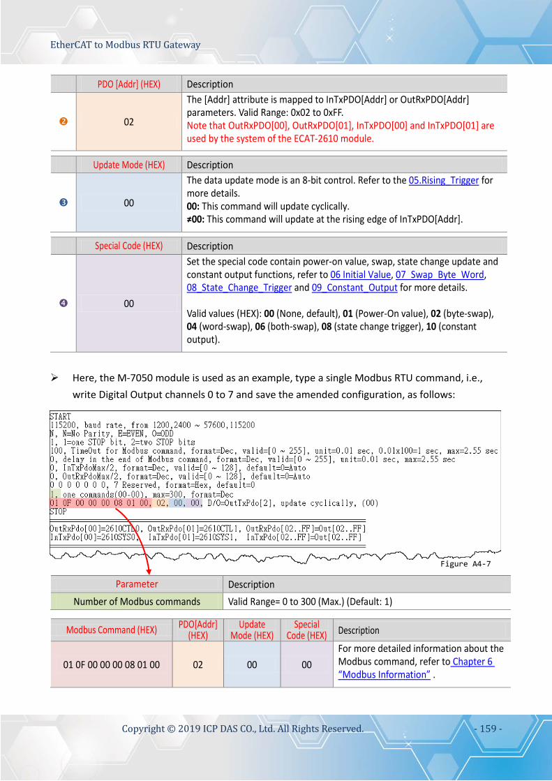
EtherCAT to Modbus RTU Gateway
Copyright © 2019 ICP DAS CO., Ltd. All Rights Reserved. - 159 -
PDO [Addr] (HEX) Description
02
The [Addr] attribute is mapped to InTxPDO[Addr] or OutRxPDO[Addr] parameters. Valid Range: 0x02 to 0xFF. Note that OutRxPDO[00], OutRxPDO[01], InTxPDO[00] and InTxPDO[01] are used by the system of the ECAT-2610 module.
Update Mode (HEX) Description
00
The data update mode is an 8-bit control. Refer to the 05.Rising_Trigger for more details. 00: This command will update cyclically. ≠00: This command will update at the rising edge of InTxPDO[Addr].
Special Code (HEX) Description
00
Set the special code contain power-on value, swap, state change update and constant output functions, refer to 06 Initial Value, 07_Swap_Byte_Word, 08_State_Change_Trigger and 09_Constant_Output for more details. Valid values (HEX): 00 (None, default), 01 (Power-On value), 02 (byte-swap), 04 (word-swap), 06 (both-swap), 08 (state change trigger), 10 (constant output).
Here, the M-7050 module is used as an example, type a single Modbus RTU command, i.e.,
write Digital Output channels 0 to 7 and save the amended configuration, as follows:
Parameter Description Number of Modbus commands Valid Range= 0 to 300 (Max.) (Default: 1)
Modbus Command (HEX) PDO[Addr]
(HEX) Update
Mode (HEX) Special
Code (HEX) Description
01 0F 00 00 00 08 01 00 02 00 00 For more detailed information about the Modbus command, refer to Chapter 6 “Modbus Information” .
Figure A4-7

EtherCAT to Modbus RTU Gateway
Copyright © 2019 ICP DAS CO., Ltd. All Rights Reserved. - 160 -
Edit the configuration data of ECAT-2610-DW
The “ECAT-2610DW_Utl_xxxxxx.zip” can be downloaded from the ICP DAS web site at: http://ftp.icpdas.com/pub/cd/fieldbus_cd/ethercat/slave/ecat-2000/software/ Decompressing the “ECAT-2610DW_Utl_xxxxxx.zip” and then you can find the “7188ECAT folder”. Copy the 7188ECAT folder to a drive on the PC host (e.g., E :\), the 7188ECAT folder should contain the following:
This folder contains additional configuration and reference files for read power meter commands, etc. Refer to Appendix A3. “Configuration Files Reference for ECAT-2610-DW” for more details.
This is the application file. Refer to A4-2 “Upload Configuration Data” for more details.
This is the Control file for the 7188ECAT application.
This is the configuration file for the Modbus RTU slave devices. The ECAT-2610-DW will use this file to communicate with the Modbus RTU slave device.
Using this file to upload the configuration data (commands.txt) to the ECAT-2610-DW module when it is connected to COM1 on the Host PC. Refer to A4-2 “Upload Configuration Data” for more details.
Using this file to upload the configuration data (commands.txt) to the ECAT-2610-DW module when it is connected to COM2 on the Host PC. Refer to A4-2 “Upload Configuration Data” for more details.
Double-click the “commands.txt” configuration file to open it.

EtherCAT to Modbus RTU Gateway
Copyright © 2019 ICP DAS CO., Ltd. All Rights Reserved. - 161 -
The “commands.txt” file provides a simple command setting that can be used to control a Modbus RTU device. A syntax rule consists of a left to right sequence of instructions, separated by a comma “,”. The data format of the commands.txt file, will be described in more detail below. The settings contained in the default commands.txt file are illustrated below:
Red Block: The parameter settings area. Green Block: The parameter description area.
Set the Baud Rate, Parity and Stop Bit values.
Parameter Description Baud Rate Valid values: 1200/2400/4800/9600/19200/38400/57600/115200 bps.
(Default: 115200) Parity Valid values: N (None), E (EVEN), O (ODD). (Default: N)
Stop Bits Valid values: 1, 2. (Default: 1)
Figure A4-8
Figure A4-9

EtherCAT to Modbus RTU Gateway
Copyright © 2019 ICP DAS CO., Ltd. All Rights Reserved. - 162 -
Set the timeout, delay time, InTxPdoMax/2 and OutRxPdoMax/2 values.
Parameter Description
Timeout Set the timeout of the Modbus command (Default: 100). Valid Range: 0 to 255. Unit = 0.01 second, 0.01 x 100 = 1 second, Max. = 2.55 second.
End_delay Time Set the delay time at the end of the command (Default: 0). Refer to End_Delay_1.txt for more details. Valid Range: 0 to 255. Unit = 0.01 second, Max. = 2.55 second.
IntxPdoMax/2 The InTxPdoMax/2 is used for debug (Default: 0). It is recommended set to 0 (Automatic settings). Refer to 15.TxPdo_RxPdo_Max for more details.
OutRxPdoMax/2 The OutRxPdoMax/2 is used for debug (Default: 0). It is recommended set 0 (Automatic settings). Refer to 15.TxPdo_RxPdo_Max for more details.
7 Reserved The second parameter (CtrlX[1]=2) is used to display value “IEEE 754 * 100.0”. The unit data format of PM-3133 Series is IEEE 754.
Set the Number of Modbus Commands.
Parameter Description Number of Modbus Commands Valid Range: 0 to 300 (Max.). (Default: 25)
Figure A4-10
Figure A4-11

EtherCAT to Modbus RTU Gateway
Copyright © 2019 ICP DAS CO., Ltd. All Rights Reserved. - 163 -
Set the Modbus commands depending on the Modbus RTU device being used, and then save the amended configuration.
No. Modbus Commands (HEX) Description
04 04 11 00 00 12 04 04 11 48 00 02 04 04 11 12 00 12
.
.
.
For more detailed information about the Modbus command, refer to Chapter 6 “Modbus Information” . For more detailed information about the communication profile area defined in PM-3000 series, refer to User Manual of PM-3000 series.
PDO [Addr] (HEX) Description
01 0A 0B . . .
The [Addr] attribute is mapped to InTxPDO[Addr] or OutRxPDO[Addr] parameters. Valid Range: 0x01 to 0x7F. Note that OutRxPDO[00] and InTxPDO[00] are used by the system of the ECAT-2610-DW module.
Update Mode (HEX) Description
00
The data update mode is an 8-bit control. Refer to the 05.Rising_Trigger for more details. 00: This command will update cyclically. ≠00: This command will update at the rising edge of InTxPDO[Addr].
Special Code (HEX) Description
20 Set the special code. Valid values (HEX): 00 (None), 08 (state change trigger), 20 (IEEE 754, default).
Figure A4-12

EtherCAT to Modbus RTU Gateway
Copyright © 2019 ICP DAS CO., Ltd. All Rights Reserved. - 164 -
Edit the configuration data of ECAT-2611
Double-click the “commands.txt” configuration file to open it. The “commands.txt” file provides a simple command setting of ECAT-2611, including the Net ID, the Baud Rate and the Data Format, etc. A syntax rule consists of a left to right sequence of instructions, separated by a comma “,”. The data format of the commands.txt file, will be described in more detail below. The settings contained in the default commands.txt file are illustrated below:
Red Block: The parameter settings area. Green Block: The parameter description area.
Figure A4-13

EtherCAT to Modbus RTU Gateway
Copyright © 2019 ICP DAS CO., Ltd. All Rights Reserved. - 165 -
Set the Baud Rate, Parity and Stop Bit values.
Parameter Description Baud Rate Valid values: 1200/2400/4800/9600/19200/38400/57600/115200 bps.
(Default: 115200) Parity Valid values: N (None), E (EVEN), O (ODD). (Default: N)
Stop Bits Valid values: 1, 2. (Default: 1) Set the timeout, Net ID, InTxPdoMax/2 and OutRxPdoMax/2 values.
Parameter Description
Timeout Set the timeout of the Modbus command (Default [DEC]: 100). Valid Range [DEC]: 0 to 255. Unit = 0.01 second, 0.01 x 100 = 1 second, Max. = 2.55 second.
Net ID Set the Net ID (Default [DEC]: 1). Valid Range [DEC]: 0 to 255. IntxPdoMax/2 InTxPdoMax = 8 X 2 = 16 = Sys0 ~ In0F (Default [DEC]: 128).
OutRxPdoMax/2 OutRxPdoMax = 10 X 2 = 20 =Ctrl0 ~ Out13 (Default [DEC]: 128). 7 Reserved These parameters are reserved and have no function. (Default[Hex]: 0 0 0 0 0 0 0)
Figure A4-14
Figure A4-15

EtherCAT to Modbus RTU Gateway
Copyright © 2019 ICP DAS CO., Ltd. All Rights Reserved. - 166 -
A4-2 Upload Configuration Data
Step 1 Connect the ECAT-2610(-DW)/2611 module to the Host PC. Switch off the power to the ECAT-2610(-DW)/2611 module. Connect the COM1 port on the ECAT-2610(-DW)/2611 module to the COM Port on the Host PC using the CA-0915 cable, as illustrated in the diagram below.
Step 2 Modify the COM Port number in execCOM1.bat file Right-click the name of the execCOM1.bat file and select the Edit option from the context menu. Change the COM Port value and save the file under a new name. The exact value will depend on COM Port (e.g., COM4) on your Host PC that is used to connect to the ECAT-2610(-DW)/2611 module.
CA-0915 Cable
Right-click
Modify this item
NOTE If the Host PC has either COM1 or COM2, the execCOM1.bat or execCOM2.bat files can be directly executed, so you can skip this step.
Figure A4-16
Figure A4-17

EtherCAT to Modbus RTU Gateway
Copyright © 2019 ICP DAS CO., Ltd. All Rights Reserved. - 167 -
Step 3 Upload the commands.txt to the ECAT-2610(-DW)/2611 module. Here, the Windows XP is used as an example. Launch a Command Prompt window by clicking the Windows Start button and opening a Run dialog. Type “cmd” in the Open field and then press Enter.
In the Command Prompt window, type E: (7188ECAT folder location on your hard drive, e.g., E) and then press Enter. Type cd 7188ecat and then press Enter. Type execcom4 and then press Enter to automatically launch the 7188ECAT.exe program. NOTE The execCOM1.bat and execCOM2.bat files are designed to use COM ports 1 and 2 on the Host PC when downloading data. If the default COM Ports on the PC is not set to 1 or 2, refer to Figure A4-17 for details of how to modify the COM Port number.
Figure A4-18
Figure A4-19
NOTE Open a Command Prompt window method depends on the version of Windows being used.

EtherCAT to Modbus RTU Gateway
Copyright © 2019 ICP DAS CO., Ltd. All Rights Reserved. - 168 -
Switch on the power to the ECAT-2610(-DW)/2611 module.
Type erase and the press Enter to erase any files that currently exist in the EEPROM.
Switch off the power to the ECAT-2610(-DW)/2611 module and then switch it back on again to reboot the module.
As this is a brand new ECAT-2610(-DW)/2611 module, a default command already exists in the EEPROM.
Type erase and then press Enter
Figure A4-20
Figure A4-21

EtherCAT to Modbus RTU Gateway
Copyright © 2019 ICP DAS CO., Ltd. All Rights Reserved. - 169 -
Simultaneously press [Ctrl] and [F4] keys on the keyboard to upload the commands.txt file to the ECAT-2610(-DW)/2611 module.
Switch off the power to the ECAT-2610(-DW)/2611 module and then switch it back on again to reboot the module.
Once the upload has been completed, click the icon in the right-top corner of the window to close it.
Figure A4-22
Starting upload
Once the upload is complete, the new configuration data will be displayed here.
Figure A4-23

EtherCAT to Modbus RTU Gateway
Copyright © 2019 ICP DAS CO., Ltd. All Rights Reserved. - 170 -
NOTES
1. If there are any errors in the configuration data (commands.txt), the ECAT-2610(-DW)/2611 module will stop and wait until you reboot it (i.e., switch the power OFF and ON) before continuing, as illustrated in Figure A4-24. Please check the configuration data (commands.txt) to correctly configure the parameters, and then upload the configuration data (commands.txt) to the ECAT-2610(-DW)/2611 module again. 2. The EEPROM is designed to store data that is not changed frequently. It is not suitable for frequent access a large amount of data, and the erase/write cycle is limited, so it should not be changed frequently when testing that it will easily cause damage to the module.
Figure A4-24

EtherCAT to Modbus RTU Gateway
Copyright © 2019 ICP DAS CO., Ltd. All Rights Reserved. - 171 -
A5. Integration with ICP DAS Modbus RTU Products
The following is a summary of the ICP DAS Modbus RTU slave devices that can be used in conjunction with the ECAT-2610 module.
Model Description
M-7000 Series
RS-485 Remote I/O Modules Website:http://www.icpdas.com/root/product/solutions/remote_io/rs-485/i-7000_m-7000/i-7000_m-7000_selection.html
M-2000 Series
RS-485 Remote I/O Modules Website:http://www.icpdas.com/root/product/solutions/remote_io/rs-485/m-2000/m-2000_selection.html
tM Series
RS-485 Remote I/O Modules Website:http://www.icpdas.com/root/product/solutions/remote_io/rs-485/tm-series/tm-series_selection.html
LC Series
Lighting Control Modules Website:http://www.icpdas.com/root/product/solutions/remote_io/rs-485/lighting_control/lighting_control_selection.html
SC Series
Lighting/Smart Control Modules Website:http://www.icpdas.com/root/product/solutions/remote_io/rs-485/smart_control/smart_control_selection.html
DL Series
Temperature and Humidity Data Logger Website:http://www.icpdas.com/root/product/solutions/remote_io/rs-485/dl_series/dl_selection.html
CL Series
PM2.5/CO/CO2/Temperature/Humidity/Dew Point Data Logger Website:http://www.icpdas.com/root/product/solutions/remote_io/rs-485/cl_series/cl_selection.html
ZT Series
ZigBee I/O Module Website:http://www.icpdas.com/root/product/solutions/industrial_wireless_communication/wireless_solutions/wireless_selection.html#e

EtherCAT to Modbus RTU Gateway
Copyright © 2019 ICP DAS CO., Ltd. All Rights Reserved. - 172 -
A6. Revision History
The following information relates to the revision history of this document.
Revision Date Description
B1.0 Oct. 2017 First Version: 8-bit version
B1.0 Mar. 2018 Second version: 16-bit version
1.1 May 2018 Initial release
1.2 Aug.2018
1. Modify the Section 4.2 use the ECAT-2610 Configuator.exe to set and upload a configuration file to ECAT-2610. 2. Added the Section 4.2.1 Restore to Factory Defaults Settings 3. Added the examples for 16.Rs485_Cycle_Time and 17.Ext_Sync
1.3 Nov. 2018 Modify the value of 2610SYS1 in the Section 3.3 Configuration and Operation.
1.4 Jan. 2019 Added the product information of ECAT-2611.
1.4.1 Apr. 2019 Modify the ECAT-2611 support function code table.
1.5 May 2019 Added the product information of ECAT-2610-DW.
Related Documents