ECLIPSE EC-5 1 EC5 SERIES LED DISPLAY USER’S MANUAL

Welcome message from author
This document is posted to help you gain knowledge. Please leave a comment to let me know what you think about it! Share it to your friends and learn new things together.
Transcript

ECLIPSE EC-5
1
EC5 SERIES LED DISPLAY USER’S
MANUAL

ECLIPSE EC-5
2
CONTENTS CAUTION ............................................................................................................................................... 3
PREFACE ............................................................................................................................................... 5
CHAPTER 1 LED CABINET ............................................................................................................ 6
1.1 CABINET STRUCTURE ................................................................................................................ 6
CHAPTER 2 CABINET CONNECTION ......................................................................................... 7
2.1 CONNECTORS AND CABINET MOUNTING SOCKET CONNECTION .............................. 7
2.2 SIGNAL AND POWER CABLE CONNECTION .................. ERREUR ! SIGNET NON DEFINI.
CHAPTER 3 LED SCREEN INSTALLATION ...................... ERREUR ! SIGNET NON DEFINI.
3.1 HANGING INSTALLATION ................................................... ERREUR ! SIGNET NON DEFINI.
3.2 FIXED INSTALLATION ............................................................................................................... 20
3.3 CURVE INSTALLATION ............................................................................................................. 21
3.4 DISLOCATION INSTALLATION .......................................... ERREUR ! SIGNET NON DEFINI.
CHAPTER 4 LED SCREEN CONTROL SYSTEM INSTALLATIONERREUR ! SIGNET NON DEFINI.
4.1 HARDWARE INSTALLATION .............................................. ERREUR ! SIGNET NON DEFINI.
4.2 SOFTWARE INSTALLATION AND SETTING .................... ERREUR ! SIGNET NON DEFINI.
CHAPTER 5 THE SETTING OF GRAPHIC CARD ............... ERREUR ! SIGNET NON DEFINI.
5.1 ATI-AGP/PCI SERIES GRAPHIC CARD ............................. ERREUR ! SIGNET NON DEFINI.
5.2 NVIDIA SERIES GRAPHIC CARD ....................................... ERREUR ! SIGNET NON DEFINI.
CHAPTER 6 COMMON PROBLEMSFOR LED SCREEN .......................................................... 1
6.1 SOFTWARE PROBLEM .......................................................... ERREUR ! SIGNET NON DEFINI.
6.2 HARDWARE PROBLEM ........................................................ ERREUR ! SIGNET NON DEFINI.
CHAPTER 7 THE MAINTENANCE OF LED SCREEN ........ ERREUR ! SIGNET NON DEFINI.
7.1 THE MAINTENANCE OF INDOOR LED SCREEN.................................................................35 7.2 THE MAINTENANCE OF OUTDOOR LED SCREEN.............................................................36
CHAPTER 8 PRODUCT PARAMETER & SPECIFICATIONERREUR ! SIGNET NON DEFINI.
APPENDIX I ......................................................................................................................................... 12
APPENDIX 2..........................................................................................................................................64
ECLIPSE EC-5
3
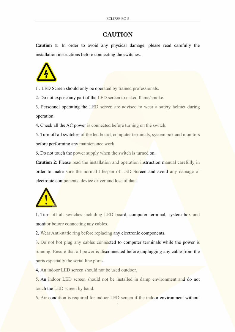
CAUTION
Caution 1: In order to avoid any physical damage, please read carefully the
installation instructions before connecting the switches.
1 . LED Screen should only be operated by trained professionals.
2. Do not expose any part of the LED screen to naked flame/smoke.
3. Personnel operating the LED screen are advised to wear a safety helmet during
operation.
4. Check all the AC power is connected before turning on the switch.
5. Turn off all switches of the led board, computer terminals, system box and monitors
before performing any maintenance work.
6. Do not touch the power supply when the switch is turned on.
Caution 2: Please read the installation and operation instruction manual carefully in
order to make sure the normal lifespan of LED Screen and avoid any damage of
electronic components, device driver and lose of data.
1. Turn off all switches including LED board, computer terminal, system box and
monitor before connecting any cables.
2. Wear Anti-static ring before replacing any electronic components.
3. Do not hot plug any cables connected to computer terminals while the power is
running. Ensure that all power is disconnected before unplugging any cable from the
ports especially the serial line ports.
4. An indoor LED screen should not be used outdoor.
5. An indoor LED screen should not be installed in damp environment and do not
touch the LED screen by hand.
6. Air condition is required for indoor LED screen if the indoor environment without

ECLIPSE EC-5
4
air condition or the indoor temperature is higher than 30 .
7. Regular electricity testing is required for indoor LED screen if long time no use.
(regular electricity testing standard : at least 2 hours in a week)
8. Special caution:Appropriate temperature and humidity is required for the LED
screen,otherwise it will damage the LED screen seriously.
Caution3: Making sure the LED screen should be properly grounded before
working.(Grounding resistance<4Ω)

ECLIPSE EC-5
5
PREFACE
On the basis of the standardized design concept and adopt the polymer
nanotechnology materials,Magic stage MG5 series can achieves over 12 compatible
modules, including YMG5-M03NFB, YMG5-M04NFB, YMG5-M04NFB-2,
YMG5-M05NFB, YMG5-M06NFB, YMG5-M07NFB, YMG5-M06UFB,
YMG5-M06UFC-2, YMG5-M07UFC, YMG5-M08UFC, YMG5-M10UFC, and
YMG5-M15UFC. The cabinet is very light, only 5.3-5.8 kg per cabinet. The product's
consistency is better and the anti-corrosion and waterproof performance are stronger
than traditional metal plated cabinet. The installation is faster and more
humanization.The aluminum alloy heat sink and power supply box are designed as a
one body, injection molding,which greatly improved heat dissipation performance.The
refresh rate is up to 3840Hz. Due to high refresh rate, image will not show dark
streaks and flashes when being captured by camera. With limitless screen size,high
brightness and curve installation, which can meet more market needs and broaden
more application, our screen has become an important choice for stage show/rent,
exhibitions, shows and commercial advertising.
To ensure that our products are used within reasonable conditions and get your
recognition,we will explain installation process,using process and cautions in details.
Please read this carefully before installing and testing screen.
Gentle hint: If there is no special description, all items should be operated under this
manual.

ECLIPSE EC-5
6
CHAPTER 1 LED CABINET The LED cabinet mainly includes power supply, modules, and receiving card. The
cover of power supply box can be fixed and protect all accessories inside. All
components inside should be neatly secured for connecting cabinets more easily.
1.1 CABINET STRUCTURE
The cabinet structure of MG5 Series products is made of special industrial material
instead of the traditional aluminum alloy die-castings or steel material so that the
cabinet weight is much lighter. The cabinet size is 500mm*500mm*73mm. (Picture
1.1.1) Based on whether there is any cable fixed on the cabinet, the cabinets can be
classified to A type and B type. (Picture 1.1.2)
A type is no cables fixed on the cabinet.
B type is 1pc signal cable and 1pc power cable fixed on each cabinet.
1.1.1 Cabinet view from all sides

ECLIPSE EC-5
7
1.1.2 A type and B type
CHAPTER 2 CABINET CONNECTION
2.1 CONNECTORS AND CABINET MOUNTING SOCKET
CONNECTION
Figure 2.1.1 Connectors for cabinet
As shown in figure 2.1.1. A (curve connector), B (horizontal connector), C (vertical
connector) and D (support structure connector) are the connectors for cabinets. The
connectors are used to join and fix the cabinets . Connectors A and B are used to
A
B
C
B
D
ECLIPSE EC-5
8
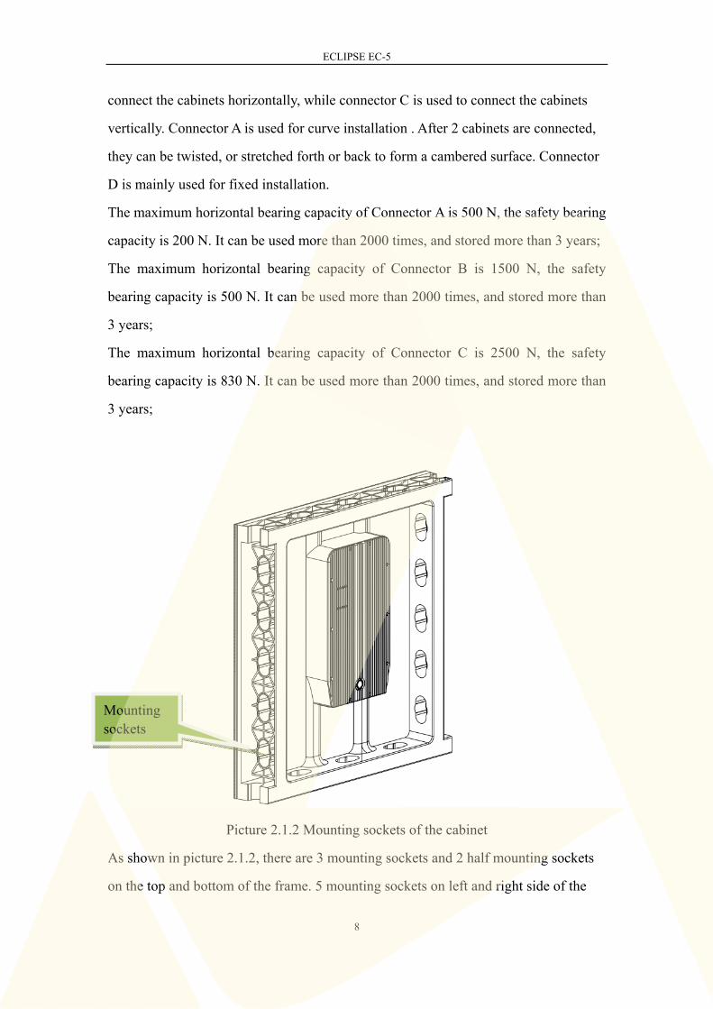
connect the cabinets horizontally, while connector C is used to connect the cabinets
vertically. Connector A is used for curve installation . After 2 cabinets are connected,
they can be twisted, or stretched forth or back to form a cambered surface. Connector
D is mainly used for fixed installation.
The maximum horizontal bearing capacity of Connector A is 500 N, the safety bearing
capacity is 200 N. It can be used more than 2000 times, and stored more than 3 years;
The maximum horizontal bearing capacity of Connector B is 1500 N, the safety
bearing capacity is 500 N. It can be used more than 2000 times, and stored more than
3 years;
The maximum horizontal bearing capacity of Connector C is 2500 N, the safety
bearing capacity is 830 N. It can be used more than 2000 times, and stored more than
3 years;
Picture 2.1.2 Mounting sockets of the cabinet
As shown in picture 2.1.2, there are 3 mounting sockets and 2 half mounting sockets
on the top and bottom of the frame. 5 mounting sockets on left and right side of the
Mounting sockets

ECLIPSE EC-5
9
frame, where the connectors can be inserted. Tightly twist the end of the connectors to
lock the cabinets in place. One by one, the cabinets can be connected easily and fast
with “one slot and one twist”.
Please note: Our standard issue of the connectors would be 3 vertical connectors (C)
and 3 horizontal connectors (B) as shown in picture 2.1.3.
Picture 2.1.3 Standard connectors for cabinet
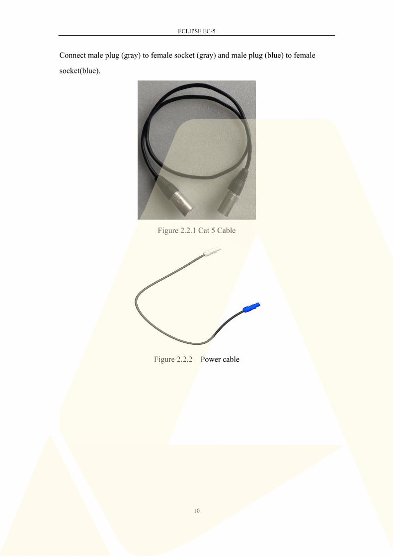
2.2 SIGNAL AND POWER CABLE CONNECTION
Between cabinets we use Cat 5 cables (signal cable) to transmit data, as shown in
Picture 2.2.1, and power cables to transmit power, shown in Picture 2.2.2. Full colored
LED screens need 2 different length of cables; Long signal cable is needed to connect
the sending card to the first cabinet of the LED screen , while short signal cable to
connect the near-by cabinets.
Signal and power cable connection are the same for both the Right-angled Cabinets
and the Slant-angled Cabinets. For each cabinet, there are 2 ports, one is the Input and
the other is Output. The Input of the cabinet would be connected to the output of the
previous cabinet, and the output would be connected to the input of the next cabinet.
The same goes for power cable connection.
Please note in Picture 2.2.2, one side of the power cable is gray, while the other is blue.
ECLIPSE EC-5
10
Connect male plug (gray) to female socket (gray) and male plug (blue) to female
socket(blue).
Figure 2.2.1 Cat 5 Cable
Figure 2.2.2 Power cable

ECLIPSE EC-5
11
Figure 2.2.3 Signal cable and power cable connection between cabinets
The both Signal ports can be flexibly as input or output according to your actual
operation, as shown in picture 2.2.3.
The source of signal cable is sending card in PC, as shown in picture 2.2.4.
Figure 2.2.4 The signal cable for sending card in PC
Signal in/out

ECLIPSE EC-5
12
Chapter 3 Installation of LED Screen For LED screen installation, we provide customers with hanging installation, fixed
installation, curved installation and dislocation installation. Customers can choose an
appropriate installation style according to the situation.
Note 1: All installation methods are required to avoid collision of the frontage 4
corners of the cabinet (as Figure 3.1), causing unnecessary damage and affecting the
normal use of the cabinet.
Figure 3.1 Cabinet front corners
Note 2: when taking out cabinet from flight case, make sure the top of the cabinet in
the same level and in a steady speed. Avoid any possible friction between the flight
case clapboard and the cabinet if the cabinet incline, which will affect the outlooking
and performance of the cabinet.
avoid collision avoid collision

ECLIPSE EC-5
13
Figure 3.2 taking out cabinets from flight case
Note 3: In general, unused cabinets must be placed in flight cases or cartons. However,
in case of no flight cases or in other special conditions, the LED should be placed
upwards, separating cabinets with foam or soft paper and then stack (stacked layers ≤
10PCS cabinet). Prohibit placing cabinet upright, in line of dominoes form (Figure
3.3).
wrong deposition

ECLIPSE EC-5
14
Figure 3.3 cabinet deposition
Note 4: When make the cascade connection of power cable and signal cable, in order
to ensure the cables in queue, cables between two cabinets can be connected through
the mounting hole. (Figure 3.4)
Figure 3.4 power cable and signal cable connection through mounting hole
right deposition paper or stack, cabinet stacked layers≤ 10PCS

ECLIPSE EC-5
15
Note 5: For B type cabinet in which the power cable and signal cable fixed, when the
show event is finished, the disassembly cabinets should be put back into the flight
case or other places, please put the power cable and signal cable as Figure 3.5, put the
cabinet in the right place after cleaning it. Handle gently when put the cabinets into
the flight case.
Figure 3.5 Cable putting
3.1 Hanging installation
The hanging method is to hang the cabinet on the hanging beam. For such installation
method, it must have a suitable installation location, such as overhead beams or lintel
being present. Furthermore, it is necessary to have a cover at the back of the LED
screen. To install in this way, it can also be mounted on TRUSS lifting frame or other
similar firm structures, as Figure 3.1.1.2.
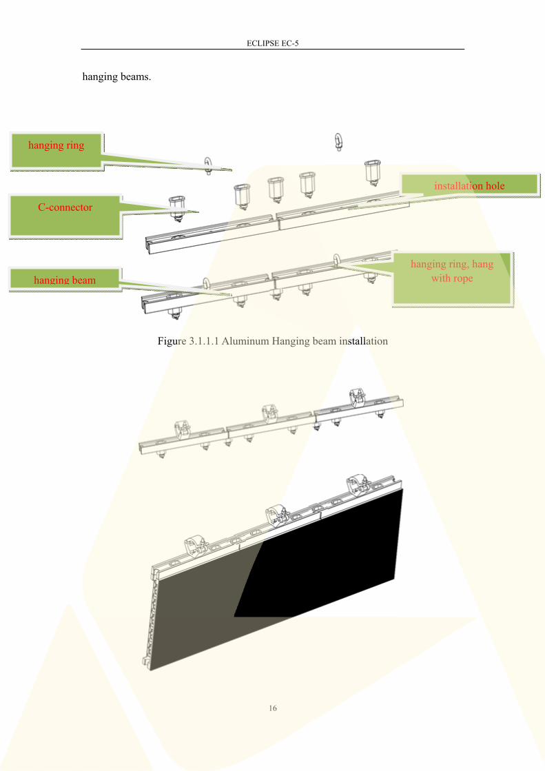
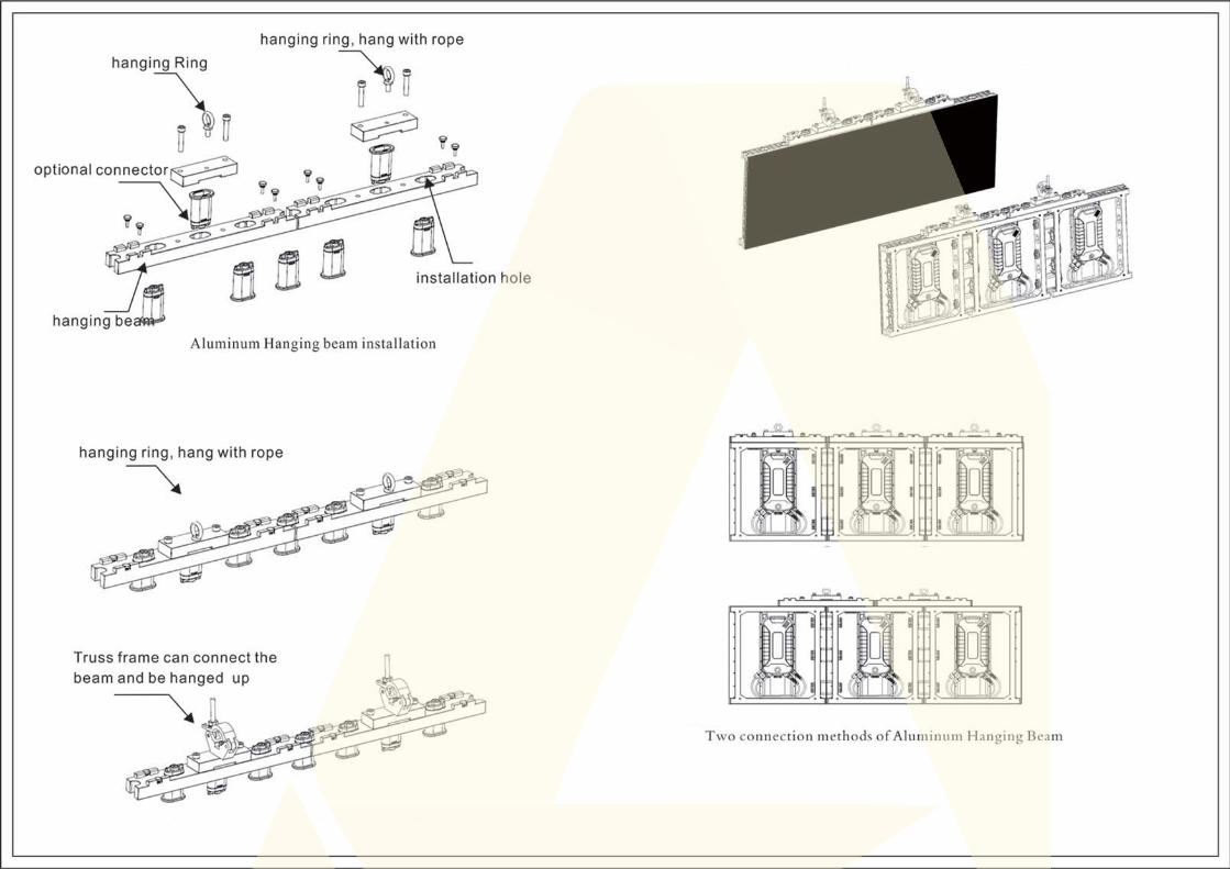
In this way, the uppermost of the display is aluminum hanging beam, and below
cabinets are connected, and then the lower cabinet is fastened with the upper one, and
the right one connected with the left one, thus it can form a whole screen. The
hanging beam structure as Figure 3.1.1.1, each complete hanging beam is made up of
several short hanging beams with 3 holes. C - connectors should be installed between
ECLIPSE EC-5
16
hanging beams.
Figure 3.1.1.1 Aluminum Hanging beam installation
hanging ring, hang with rope
hanging ring
hanging beam
C-connector
installation hole

ECLIPSE EC-5
17
Figure 3.1.1.2 Hanging beam mounted on TRUSS lifting frame
There are two connection methods between hanging beam and the cabinet : 1, the
hanging beam is aligned with a single cabinet; 2, dislocation installation across two
cabinets. Here we recommend the second way, as shown in Figure 3.1.1.3.
Figure 3.1.1.3 Two connection methods of Aluminum Hanging Beam
According to our test, for choosing the hole quantity of each hanging beam, if use 4
holes of the aluminum hanging beam, the load weight is 2861N and security index is
3:1, 95kg, and it is safe within 16 cabinets’ height. Therefore, we should pay special
attention to choosing the quantity of connectors, using 4 pieces of C - connectors.
Method 1
Method 2

ECLIPSE EC-5
18
Also, it is safe to keep the angle between rope and hanging beam to be 85°- 95° in
hanging installation. Design sketch is shown as Figure 3.1.4 & 3.1.5.
Note: use hanging rope for hanging installation, make sure every rope bear the weight
(rope in a tight condition). If the hanging height < 8 cabinets, using two C -
connectors between cabinets; if the hanging height > 8 cabinets, using three C -
connectors between cabinets.
Figure 3.1.1.4 Front side design sketch of hanging installation
install hanging rope here 85°- 95°
C - connector
hanging beam
installation
B - connector

ECLIPSE EC-5
19
Figure 3.1.1.5 Two installation methods of cabinets, design sketch in back side
2. In addition, the hanging beam can also be used as ground support: When the ground
is not flat, it can ensure smooth installation of the screen, as Figure 3.1.2.1, 3.1.2.2.
Figure 3.1.2.1 design sketch of ground support installation in back side
Figure 3.1.2.2 design sketch of ground support installation in back side

ECLIPSE EC-5
20
3.2 Fixed installation
Fixed installation means that the cabinet is attached to the wall or steel pole, fixed by
connectors. The wall must be solid or there is concrete beam at the hanging place.
Using the connectors between cabinets and fixing on steel pole, which is fixed in the
wall, then ensure the stableness.
The difference between fixed installation and hanging installation is the former uses
connector (D - connector as Figure 2.1.1) fixing on steel pole rather than through
hanging beam. C - connectors must be installed 3 pieces, as Figure 3.2.2, 3.2.2.
Figure 3.2.1 design sketch of fixed installation in front side

ECLIPSE EC-5
21
Figure 3.2.2 Design sketch of fixed installation in back side
3.3 Curving installation
Curving installation adopts special connector to connect cabinet with each other, by
twisting the connector to form arc screen.
Full color screen curving installation is formed by using the curved connector which
can be reversed (show as Figure 3.3.1 A - connector). Customers can install the
cabinet in outer arc, inner arc and “S” shape according to own requirements.
D - connector is used for fixed installation,
choosing the appropriate mounting hole

ECLIPSE EC-5
22
Figure 3.3.1 Curving installation diagram
As shown in Figure 3.3.1, install two cabinets as curved screen: Use A - connector,
ensure the cabinet surface is smooth, then twist two ends of A - connector, then
tighten the above butterfly screw.
A-connector,
turn here to
tighten
Outer Arc

ECLIPSE EC-5
23
Figure 3.3.2 Top view of curved installation
3.4 Dislocation Installation
Compared to traditional LED display, MG5 is designed with multiple dislocation
mounting holes, providing a great possibility for customers’ creative installation.
Different installation chooses different holes , see the details as Figure 3.4.1
. Figure 3.4.1 Dislocation installation (creative design)

ECLIPSE EC-5
24
Chapter 4 LED Screen Control System Installation
4.1 Hardware Installation
Control system of MG5 series is Nova. Nova sending card as showed below.
Figure 4.1.1 USB control cable, DVI signal cable and sending card
2. As picture 4.1.2 and 4.1.3, the control equipment of LED display includes computer,
sending card (or sending box), DVI signal cable, USB control cable, and internet
cable.
3. The sending card need to be installed at the computer PCI interface or in the video
DVI signal cable USB control cable
USB port
Internet cable port
DVI port
Sending card
PCI port

ECLIPSE EC-5
25
processor, and then insert each data cable into corresponding interface as per picture
4.1.4 and picture 4.1.6.
4. Internet cable: the RJ45 connector connect to the sending card, the aviation
connector connects indoor full-color LED display cabinet.
5. DVI data cable: Two ends are the same, one connects the graphic card, and the
other connects the sending card.
6. USB data cable: the big end connects the computer USB interface, the small end
connects the sending card
Figure 4.1.2 Cat 5 Cable (To connect sending card to indoor LED cabinet )
Figure 4.1.3 Sending card in video processor
Sending card
ECLIPSE EC-5
26
Figure 5.1.1
Chapter 6 Common Problems for LED Screen
6.1 Software Problems
1. Connection interruption or prompt unable to find the
control card when star the software, or the interface of the software is not adjustable,
that is,gray status, and there is no main controlling icon of the software LED control
equipment list.
Solution:
Change USB cable.
Check the equipment connection in the equipment manager.
Ensure that the computer is without virus.
If sending card installs in the computer, it is probably due to the loose slot or dirty
PCI. Please insert sending card again or clean PCI interface by rubber.
2. Indicator light of the output port for sending card is extinguished.
Solution: Two conditions probably:
Relevant control software has not been installed, please ensure the installation.
The FPD of the Graphics card is closed. Please right click “my computer” on the
desktop, and then click properties-> setting-> advanced> display-> FPD.
6.2 Hardware problems
1. There is no content on the LED screen
Solution: There are various reasons, first, please check the screen is powered, and the
power cable and signal cable are well connected.
2. The cabinet of the indoor full color LED screen is blurred or no bright in blocks.
Solution: Please check the flat cable of the led module to see if cables are well
connected..
3. The picture of the cabinet is in a wrong order
ECLIPSE EC-5
27
Solution: The signal cable between the cabinet is connected incorrectly.
4. Some individual LED lamps are extinguished
Solution: Please replace these faulty LEDs by professionals.
Chapter 7 The Maintenance of LED Screen
Use the LED display correctly is very important for the lifespan of the LED display
and normal work. Daily maintenance of display must be finished carefully.
7.1 Maintenance of Indoor Led Screen
1. Please read the Installation and Operation Instruction of the Magic Stage series
Full Color LED Display. The manufacturer do not take any legal liability to the
consequence due to the incorrect, incomplete, irresponsible, or unsafe use installation
system.
2. Moving screen in gentle, no collision and strike.
3. Check the cabinet if there's any loose screw before using.
4. Please confirm the steel frame or rings are kept in place firmly before installation,
for the screen having been installed for long time, the situation of the joining and
hanging part should be checked regularly. If loose part is found, adjust it timely,
reinforce or change hanging parts in time.
5. Keep the cabinet frame structure away from oil, acid and other corrosive substance.
6. Pay attention to the anti-static work of the screen, do not touch the LED face
directly by hand, wearing gloves for the installation and debugging of the screen is
suggested.
7. Null line and live wire of the computer and control system can't be connected
reversely; it should be connected strictly according to the original position.
8. If the power switch trips happened frequently, please check the screen or replace
the power supply switch.
9. Please open the PC first, then the LED screen; After using the display, first, turn off
the LED screen, then shut off PC (If shut off PC first, high bright spot will appear,
then lamp will be burnt, leading serious consequences).

ECLIPSE EC-5
28
10. If there is short circuit, switch trip, wire burning, smoke and other abnormal
phenomenon after removing, please don't repeat electricity test, and check the
problem timely.
11. The proper way to remove a power supply: turn the cabinet back up and keep the
connector upward; loosen the screws on aluminum cooling board and lift up
horizontally to 30 ~ 40mm (meanwhile observing the power supply interior), overturn
to right slowly (Attention to prevent radiator’s fan crashing other component), then
start checking and repairing.
12. Master the installation method, the original data recovery, backup, and
controlling parameter setting, basic data preset modification.
13. Inspect virus regularly, and remove irrelevant data.
14. No professional person, no operating the software system.
7.2 Maintenance of Outdoor Led Screen
1. Please read the Installation and Operation Instruction of the Magic Stage series
Full Color LED Display. The manufacturer do not take any law liability to the
consequence due to the incorrect, incomplete, irresponsible, or unsafe use installation
system.
2. Moving screen in gentle, no collision and strike.
3. Check the cabinet if there's any loose screw before using.
4. Please confirm the steel frame or rings are kept in place firmly before installation,
for the screen having been installed for long time, the situation of the joining and
hanging part should be checked regularly. If loose part is found, adjust it timely,
reinforce or change hanging parts in time.
5. Keep the cabinet frame structure away from oil, acid and other corrosive substance.
6. Pay attention to the anti-static work of the screen, do not touch the LED face
directly by hand, wearing gloves for the installation and debugging of the screen is
suggested.
7. Null line and live wire of the computer and control system can't be connected

ECLIPSE EC-5
29
reversely; it should be connected strictly according to the original position.
8. If the power switch trips happened frequently, please check the screen or replace
the power supply switch.
9. Please open the PC first, then the LED screen; After using the display, first, turn off
the LED screen, then shut off PC (If shut off PC first, high bright spot will appear,
then lamp will be burnt, leading serious consequences).
10. If there is short circuit, switch trip, wire burning, smoke and other abnormal
phenomenon after removing, please don't repeat electricity test, and check the
problem timely.
11. The proper way to remove a power supply: turn the cabinet back up and keep the
connector upward; loosen the screws on aluminum cooling board and lift up
horizontally to 30 ~ 40mm (meanwhile observing the power supply interior), overturn
to right slowly (Attention to prevent radiator’s fan crashing other component), then
start checking and repairing.
12. Master the installation method, the original data recovery, backup, and
controlling parameter setting, basic data preset modification.
13. Inspect virus regularly, and remove irrelevant data.
14. No professional person, no operating the software system.
15. Please do not perform in the storm and strong wind.
16. Dismantle LED display after the events, please clean the water stains and dust on
the two sides of the cabinet before putting into the flight case, which must be kept
clean and dry, at the same time, too much friction should be avoided between cabinet
and inner part of the flight case.
17. Please protect the LED at the edge of cabinet when dismantle the screen, to
prevent damage of LEDs.

ECLIPSE EC-5
30
Chapter 8 Product Parameters & Specification
Product No. EC5-M03NFD
Product Category P3.9 indoor full color led display
Cabinet Size 500×500×73mm
Pixel Pitch 3.9mm
Pixel Density 65536dot/
LED Encapsulation 2020 (Black Led)
Working Voltage AC 86-264V 50-60Hz
Average power
consumption
88w/cabinet
Max. Power
consumption
174w/cabinet
Brightness 1500 cd/
Viewing Angle(H/V) 150°/120°
Gray Scale Recommended single color 4096 grade (adjustable under
software 2BIT to 16BIT)
Driving Method 1/16 Dynamic scanning
Display Color 64G(under 4096 grad scale)
Led Module brightness
proportionality
<5%
Brightness Adjustment Brightness R.G.B color can be adjusted by software
Communication method HSYV
Effective
communication distance
100M
Refresh frequency <3840hz
Working environment
temperature
-20~50

ECLIPSE EC-5
31
Working environment
humidity
10~90%
Malfunction dot rate <0.00003
Average no failure time >10000 hours
Life span >100000 hours
Display content Text,graphics,logo,animation,live,video,etc
Cabinet material Polymer nanomaterial
Curved installation
angle
Inner curve 15°,outer curve 15°
Weight 5.2 kg/cabinet
Control system Nova, Mooncell
Input signal Synchronization with PC;TV,DVD player,VCD player,
VCR,camcorder,etc(need video processor)
Certificate CE, FCC
Product No. EC5-M04NFD
Product Category P4.4 indoor full color led display
Cabinet Size 500×500×73mm
Pixel Pitch 4.46mm
Pixel Density 50176dot/
LED Encapsulation 2020
Working Voltage AC 86-264V 50-60Hz
Average power
consumption
88w/cabinet
Max. Power consumption 180w/cabinet
Brightness 1500 cd/
Viewing Angle(H/V) 160°/120°
Gray Scale Recommended single color 4096 grade (adjustable under

ECLIPSE EC-5
32
software 2BIT to 16BIT)
Driving Method 1/14Dynamic scanning
Display Color 64G(under 4096 grad scale)
Led Module brightness
proportionality
<5%
Brightness Adjustment Brightness R.G.B color can be adjusted by software
Communication method HSYV
Effective communication
distance
100M
Refresh frequency <3840hz
Working environment
temperature
-20~50
Working environment
humidity
10~90%
Malfunction dot rate <0.00003
Average no failure time >10000 hours
Life span >100000 hours
Display content Text,graphics,logo,animation,live,video,etc
Cabinet material Polymer nanometerial
Curved installation angle Inner curve 15°,outer curve 15°
Weight 5.3 kg/cabinet
Control system Nova, Mooncell
Input signal Synchronization with PC;TV,DVD player,VCD player,
VCR,camcorder,etc(need video processor)
Certificate CE,FCC

ECLIPSE EC-5
33
Product No. EC5-M04NFD-2
Product Category P4.8 indoor full color led display
Cabinet Size 500×500×73mm
Pixel Pitch 4.8mm
Pixel Density 43264dot/
LED Encapsulation 2020(black let)
Working Voltage AC 86-264V 50-60Hz
Average power
consumption
94w/cabinet
Max. Power
consumption
188w/cabinet
Brightness 1200 cd/
Viewing Angle(H/V) 150°/120°
Gray Scale Recommended single color 4096 grade (adjustable under
software 2BIT to 16BIT)
Driving Method 1/13Dynamic scanning
Display Color 64G(under 4096 grad scale)
Led Module brightness
proportionality
<5%
Brightness Adjustment Brightness R.G.B color can be adjusted by software
Communication method HSYV
Effective
communication distance
100M
Refresh frequency <3840hz
Working environment
temperature
-20~50
Working environment
humidity
10~90%

ECLIPSE EC-5
34
Malfunction dot rate <0.00003
Average no failure time >10000 hours
Life span >100000 hours
Display content Text,graphics,logo,animation,live,video,etc
Cabinet material Polymer nanometerial
Curved installation
angle
Inner curve 15°,outer curve 15°
Weight 5.3 kg/cabinet
Control system Nova, Mooncell
Input signal Synchronization with PC;TV,DVD player,VCD player,
VCR,camcorder,etc(need video processor)
Certificate CE,FCC
Remark Magnet mounted, Snap Joints mask design
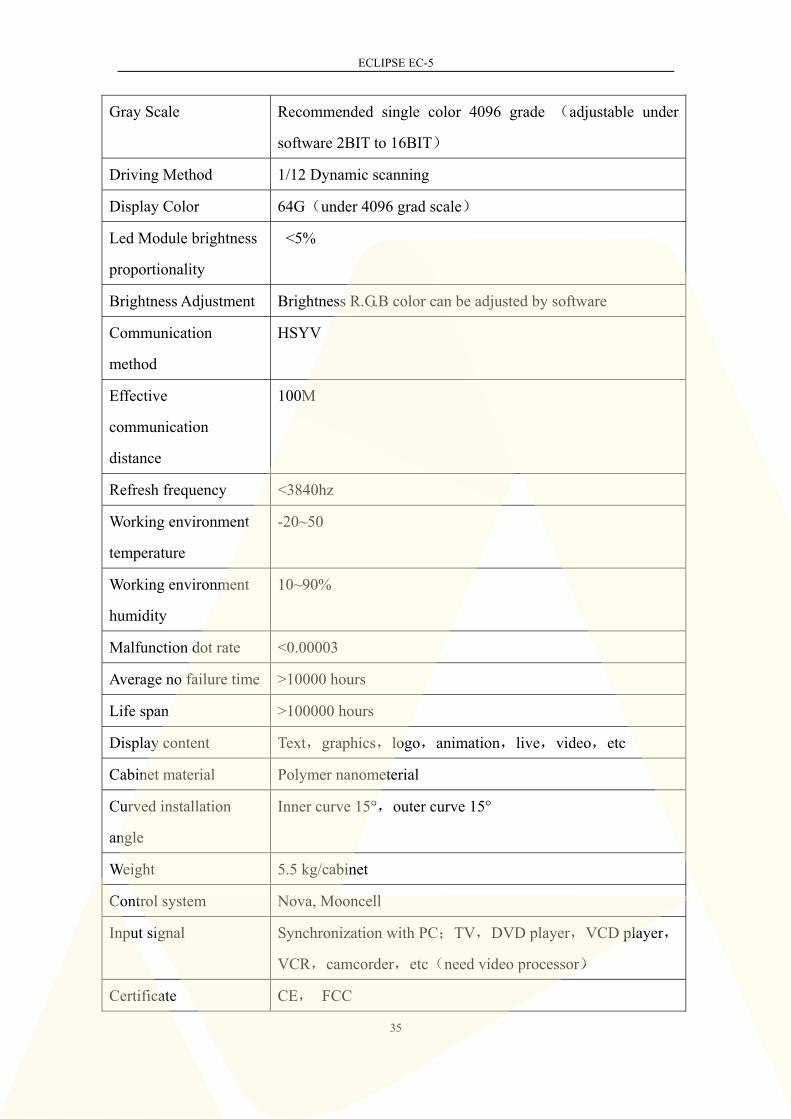
Product No. EC5-M05NFB
Product Category P5.2 indoor full color led display
Cabinet Size 500×500×73mm
Pixel Pitch 5.2mm
Pixel Density 36864dot/
LED Encapsulation 3528
Working Voltage AC 86-264V 50-60Hz
Average power
consumption
85w/cabinet
Max. Power
consumption
170w/cabinet
Brightness 1500 cd/
Viewing Angle(H/V) 160°/120°
ECLIPSE EC-5
35
Gray Scale Recommended single color 4096 grade (adjustable under
software 2BIT to 16BIT)
Driving Method 1/12 Dynamic scanning
Display Color 64G(under 4096 grad scale)
Led Module brightness
proportionality
<5%
Brightness Adjustment Brightness R.G.B color can be adjusted by software
Communication
method
HSYV
Effective
communication
distance
100M
Refresh frequency <3840hz
Working environment
temperature
-20~50
Working environment
humidity
10~90%
Malfunction dot rate <0.00003
Average no failure time >10000 hours
Life span >100000 hours
Display content Text,graphics,logo,animation,live,video,etc
Cabinet material Polymer nanometerial
Curved installation
angle
Inner curve 15°,outer curve 15°
Weight 5.5 kg/cabinet
Control system Nova, Mooncell
Input signal Synchronization with PC;TV,DVD player,VCD player,
VCR,camcorder,etc(need video processor)
Certificate CE, FCC
ECLIPSE EC-5
36
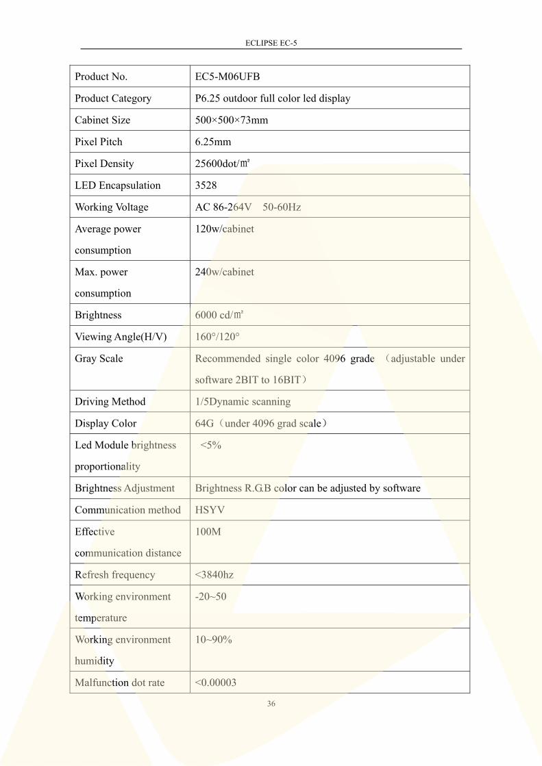
Product No. EC5-M06UFB
Product Category P6.25 outdoor full color led display
Cabinet Size 500×500×73mm
Pixel Pitch 6.25mm
Pixel Density 25600dot/
LED Encapsulation 3528
Working Voltage AC 86-264V 50-60Hz
Average power
consumption
120w/cabinet
Max. power
consumption
240w/cabinet
Brightness 6000 cd/
Viewing Angle(H/V) 160°/120°
Gray Scale Recommended single color 4096 grade (adjustable under
software 2BIT to 16BIT)
Driving Method 1/5Dynamic scanning
Display Color 64G(under 4096 grad scale)
Led Module brightness
proportionality
<5%
Brightness Adjustment Brightness R.G.B color can be adjusted by software
Communication method HSYV
Effective
communication distance
100M
Refresh frequency <3840hz
Working environment
temperature
-20~50
Working environment
humidity
10~90%
Malfunction dot rate <0.00003

ECLIPSE EC-5
37
Average no failure time >10000 hours
Life span >100000 hours
Display content Text,graphics,logo,animation,live,video,etc
Cabinet material Polymer nanomaterial
Curved installation angle Inner curve 15°,outer curve 15°
IP Grade Front: IP65/Back:IP54 (Upright position)
Weight 5.8 kg/cabinet
Control system Nova, Mooncell
Input signal Synchronization with PC;TV,DVD player,VCD player,
VCR,camcorder,etc(need video processor)
Certificate CE,FCC
Product No. EC5-M07UFC
Product Category P7.8 outdoor full color led display
Cabinet Size 500×500×73mm
Pixel Pitch 7.8mm
Pixel Density 16384dot/
LED Encapsulation 3535
Working Voltage AC 86-264V 50-60Hz
Average power
consumption
94w/cabinet
Max.power
consumption
188w/cabinet
Brightness 6000 cd/
Viewing Angle(H/V) 160°/120°
Gray Scale Recommended single color 4096 grade (adjustable under
software 2BIT to 16BIT)

ECLIPSE EC-5
38
Driving Method 1/4Dynamic scanning
Display Color 64G(under 4096 grad scale)
Led Module brightness
proportionality
<5%
Brightness Adjustment Brightness R.G.B color can be adjusted by software
Communication method HSYV
Effective
communication distance
100M
Refresh frequency <3840hz
Working environment
temperature
-20~50
Working environment
humidity
10~90%
Malfunction dot rate <0.00003
Average no failure time >10000 hours
Life span >100000 hours
Display content Text,graphics,logo,animation,live,video,etc
Cabinet material Polymer nanomaterial
Curved installation
angle
Inner curve 15°,outer curve 15°
IP Grade Front: IP65/Back IP54(Upright position)
Weight 6.0 kg/cabinet
Control system Nova, Mooncell
Input signal Synchronization with PC;TV,DVD player,VCD player,
VCR,camcorder,etc(need video processor)
Certificate CE, FCC

ECLIPSE EC-5
39
Product No. EC5-M08UFC
Product Category P8.9 outdoor full color led display
Cabinet Size 500×500×73mm
Pixel Pitch 8.9mm
Pixel Density 12544 dot/
LED Encapsulation 3535
Working Voltage AC 86-264V 50-60Hz
Average power
consumption
90w/cabinet
Max.power consumption 180w/cabinet
Brightness 5500 cd/
Viewing Angle(H/V) 160°/120°
Gray Scale Recommended single color 4096 grade (adjustable under
software 2BIT to 16BIT)
Driving Method 1/4Dynamic scanning
Display Color 64G(under 4096 grad scale)
Led Module brightness
proportionality
<5%
Brightness Adjustment Brightness R.G.B color can be adjusted by software
Communication method HSYV
Effective communication
distance
100M
Refresh frequency <3840hz
Working environment
temperature
-20~50
Working environment
humidity
10~90%
Malfunction dot rate <0.00003

ECLIPSE EC-5
40
Average no failure time >10000 hours
Life span >100000 hours
Display content Text,graphics,logo,animation,live,video,etc
Cabinet material Polymer nanomaterial
Curved installation angle Inner curve 15°, outer curve 15°
IP Grade Front: IP65/Back: IP54(Upright position)
Weight 6.0kg/cabinet
Control system Nova, Mooncell
Input signal Synchronization with PC;TV,DVD player,VCD player,
VCR,camcorder,etc(need video processor)
Certificate CE,FCC
Product No. EC5-M10UFC
Product Category P10.4 outdoor full color led display
Cabinet Size 500×500×73mm
Pixel Pitch 10.4mm
Pixel Density 9216dot/
LED Encapsulation 3535
Working Voltage AC 86-264V 50-60Hz
Average power
consumption
65w/cabinet
Max.power consumption 130w/cabinet
Brightness 5500 cd/
Viewing Angle(H/V) 160°/120°
Gray Scale Recommended single color 4096 grade (adjustable under
software 2BIT to 16BIT)
Driving Method 1/4Dynamic scanning
Display Color 64G(under 4096 grad scale)
ECLIPSE EC-5
41
Led Module brightness
proportionality
<5%
Brightness Adjustment Brightness R.G.B color can be adjusted by software
Communication method HSYV
Effective communication
distance
100M
Refresh frequency <3840hz
Working environment
temperature
-20~50
Working environment
humidity
10~90%
Malfunction dot rate <0.00003
Average no failure time >10000 hours
Life span >100000 hours
Display content Text,graphics,logo,animation,live,video,etc
Cabinet material Polymer nanomaterial
Curved installation angle Inner curve 15°, outer curve 15°
IP Grade Front: IP65/Back: IP54(Upright position)
Weight 6.0 kg/cabinet
Control system Nova, Mooncell
Input signal Synchronization with PC;TV,DVD player,VCD player,
VCR,camcorder,etc(need video processor)
Certificate CE,FCC
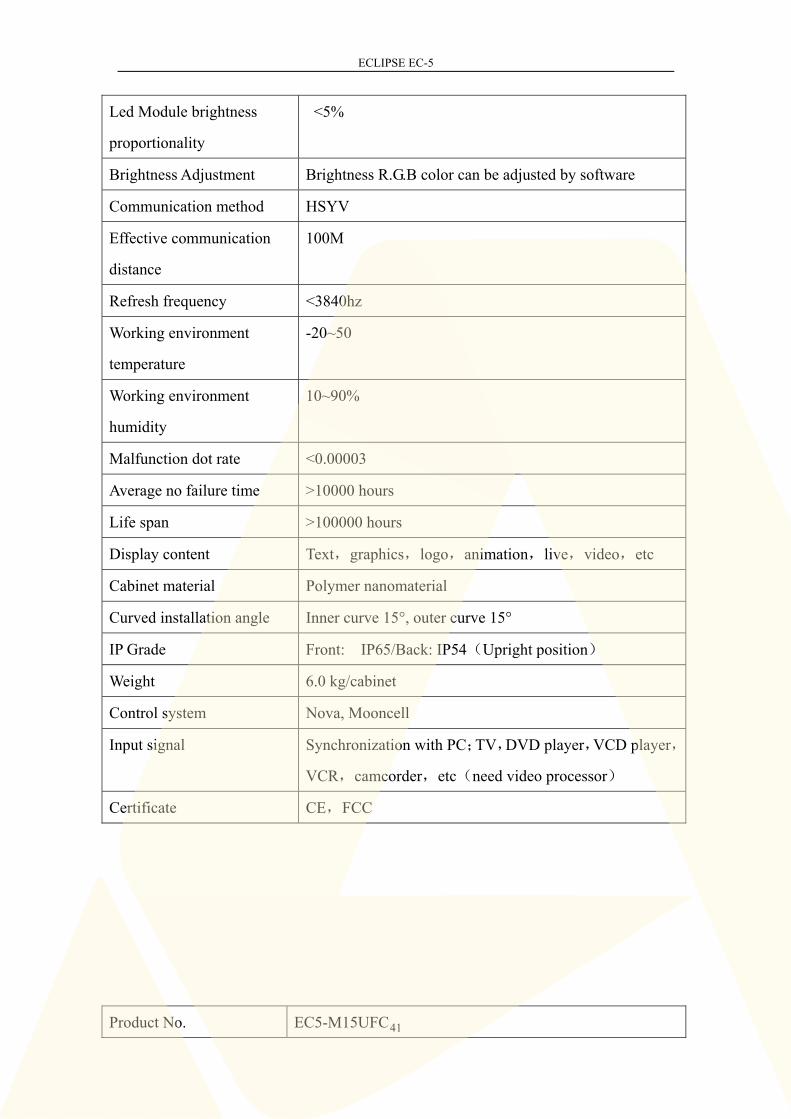
Product No. EC5-M15UFC

ECLIPSE EC-5
42
Product Category P15.6 outdoor full color led display
Cabinet Size 500×500×73mm
Pixel Pitch 15.6mm
Pixel Density 4096dot/
LED Encapsulation 3535
Working Voltage AC 86-264V 50-60Hz
Average power
consumption
115w/cabinet
Max.power consumption 230w/cabinet
Brightness 6000 cd/
Viewing Angle(H/V) 160°/120°
Gray Scale Recommended single color 4096 grade (adjustable under
software 2BIT to 16BIT)
Driving Method Static
Display Color 64G(under 4096 grad scale)
Led Module brightness
proportionality
<5%
Brightness Adjustment Brightness R.G.B color can be adjusted by software
Communication method HSYV
Effective communication
distance
100M
Refresh frequency <3840hz
Working environment
temperature
-20~50
Working environment
humidity
10~90%
Malfunction dot rate <0.00003
Average no failure time >10000 hours
Life span >100000 hours

ECLIPSE EC-5
43
Appendix I
Display content Text,graphics,logo,animation,live,video,etc
Cabinet material Polymer nanomaterial
Curve installation angle Inner curve 15°, outer curve 15°
IP Grade Front: IP65/Back: IP54(Upright position)
Weight 6.0 kg/cabinet
Control system Nova, Mooncell
Input signal Synchronization with PC;TV,DVD player,VCD player,
VCR,camcorder,etc(need video processor)
Certificate CE,FCC

ECLIPSE EC-5
44
Software installation of NOVA control system
Use NOVA control system(NOVA) please install the software first, double- click
NovaLCT-Mars(Picture 1) to start the installation.
图 1 Picture 1
Select the language
Click“Next”
Select destination location, click“Next”
ECLIPSE EC-5
45
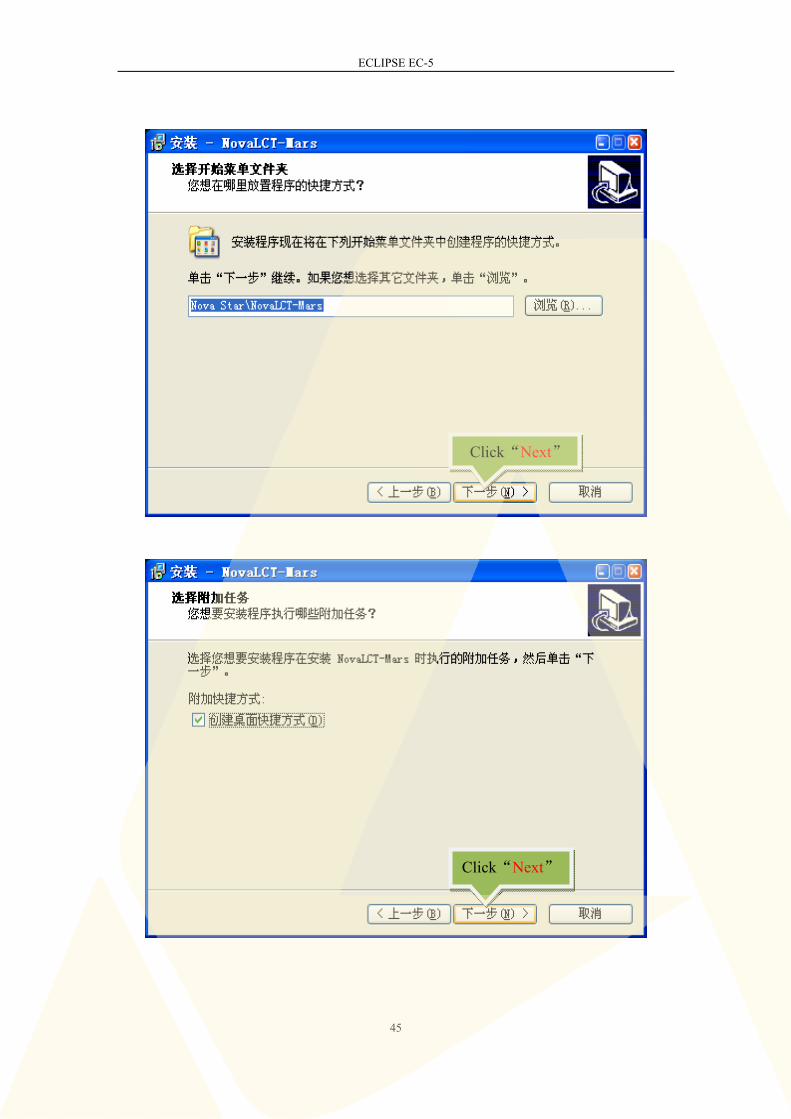
Click“Next”
Click“Next”
ECLIPSE EC-5
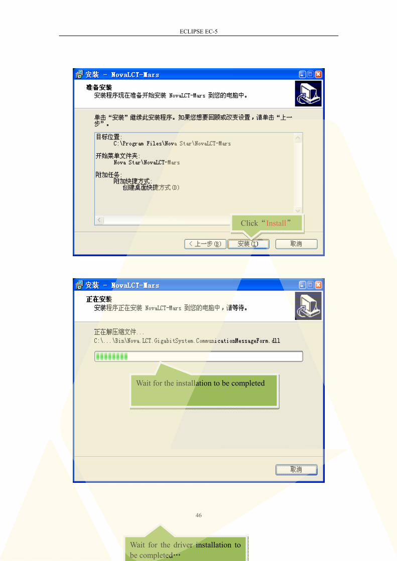
46
Click“Install”
Wait for the driver installation to be completed…
Wait for the installation to be completed

ECLIPSE EC-5
47
After the installation is completed, click [Start]/ [Programs]/ [NOVA STAR]/
[NovaLCT-Mars] to run the software. Also a shortcut(Figure 2) can be found on
desktop, double-click the icon to start program.
Figure 2
Software setting of NOVA control system
Corresponding setting for receiving cards is needed to make sure NOVA system can
Wait for the driver installation complete…
Click“Finish”

ECLIPSE EC-5
48
correctly controls the cabinet receiving cards and display the content. Please follow
below steps for the setting.
Click “User”>>“Advanced login”
Password: 666
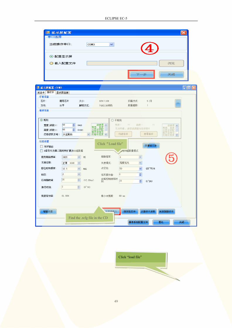
Click“screen config”
Click“Next”
ECLIPSE EC-5
49
Find the .rcfg file in the CD
Click “load file”
Click“Load file”
ECLIPSE EC-5
50
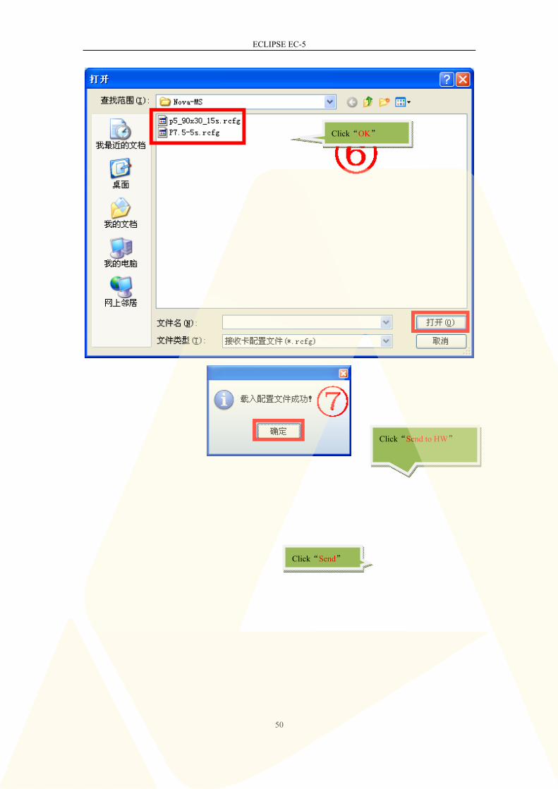
Click“OK”
Click“Send to HW”
Click“Send”

ECLIPSE EC-5
51
Wait for the data
transmission complete
Click“OK”
ECLIPSE EC-5
52
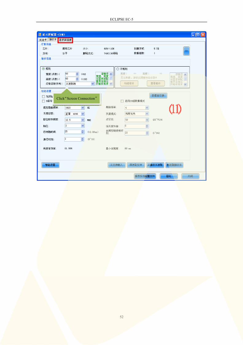
Click“Screen Connection”

ECLIPSE EC-5
53
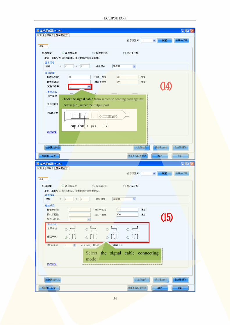
Input the receiving card quantity
for each row & line
Input the cabinet pixel
ECLIPSE EC-5
54
Check the signal cable from screen to sending card against
below pic., select the output port
Select the signal cable connecting mode

ECLIPSE EC-5
55
The screen can start to work properly after the transmission is completed.
Please read software menu “help’-’user file’-’receiving card electrical relay” for
instruction of fan control
Click“Send to HW”
Wait for the data
transmission complete
Click“OK”

ECLIPSE EC-5
56
Appendix 2 Parts list
No. Parts Specification remark
1 Cabinet 500mm*500mm*73mm,static package +
+ carton
Standard
2 Up-down connector 3 connectors for 1 cabinet Standard
3 Right-left connector 3 connectors for 1 cabinet Standard
4 Curve connector 2 connectors for 1 cabinet Extra pay
5 Hanging beam 3 up-down connectors for 1 aluminum
hanging beam
Extra pay
6 Steel structure
connector
1 connector for 4 cabinets, shape design
discussed with exact quantity
Check with
financial depart.
7 Signal cable A type cabinet equips one 900mm length
signal cable;B type cabinet equips one
1000mm length signal cable
Standard
8 Power cable A type cabinet equips one 800mm length
power cable;B type cabinet equips one
930mm length power cable.
Standard
9 Signal input cable Depends on screen size (15M for free) Standard
10 Power input cable One cable for 6 cabinets (one side with
Powercon connector, other side connect
input voltage) (5M for free)
Standard
11 Flight case 10 cabinets + accessories in one flight
case
Extra pay
Related Documents