Source of Acqu~s~t~on EACH AND EVEF(Y &+EC 8 fSh3 G(E~~RT: ik+- XBSERCOOLER DES IC;N FOR AIRCBABT Bg M, J, $rovoorL, U, 5, Joyner, ad Me Leifer L~nglcy Wenorial Aeronautical Laboratory Soptsnber 1939 https://ntrs.nasa.gov/search.jsp?R=20090014806 2018-06-08T15:39:44+00:00Z

Welcome message from author
This document is posted to help you gain knowledge. Please leave a comment to let me know what you think about it! Share it to your friends and learn new things together.
Transcript
Source of A c q u ~ s ~ t ~ o n
EACH AND EVEF(Y
&+EC 8 f S h 3 G ( E ~ ~ R T : ik+-
XBSERCOOLER DES IC;N FOR AIRCBABT
Bg M, J, $rovoorL, U, 5, Joyner, a d M e L e i f e r L ~ n g l c y Wenorial Aeronautical Laboratory
Soptsnber 1939
https://ntrs.nasa.gov/search.jsp?R=20090014806 2018-06-08T15:39:44+00:00Z

INTERCOOLEB DZSIGN FOR AIBC-UFT
By M. J. B r e v o o r t , U. T , J o y n e r , and M. Z e i f e r
SUMMARY
Data on h e a t t r a n s f e r a n d p r e s s u r e l o s s e s f o r f low m i t h i n c i r c u l a r and r e c t a n g u l a r t u b e s and f o r f low perpen- d i c u l a r t o tube banks a r e c o l l e c t e d and p r e s e n t e d . These d a t a , t o g e t h e r w i t h a g iven s e t of d e s i g n c o n d i t i o n s , a r e s u f f i c i e n t f o r t h e c a l c u l a t i o n of a n optimum i n t o r c o o l o r d e s i q n based on t h e t o t a l pomer c h a r g e a b l e t o t h e i n t e r - c o o l e r . The t o t a l power i s t h e sum of t h e powers oxpended i n pumping t h e charge a i r and t h e c o o l i n g a i r th rough t h e i n t e r c o o l e r and t h e power u s e d t o t r a n s p o r t t h e weight of t h e i n t e r c o o l e r .
The d e s i g n i s accompl ished by c o n s i d e r i n g t h e power c h a r g e a b l e t o each of a s e r i e s of i n t e r c o o l e r s o b t a i n e d by a s y s t e m a t t c v a r i a t i o n of t h e v a r i a b l e s of t h e des ign . A l l t h e i n t e r c o o l e r s c o n s i d e r a d s a t i s f y t h e d e s i ~ n condi- t i o n s ,
Three t y p e s of i n t e r c o o l e r a r e c o n s i d e r e d : a coun te r - f low i n t e r c o o l e r w i t h i n d i r e c t - c o o l i n g s u r f a c e s i n t h e form of f i n s , a coun te r f low i n t e r c o o l e r w i t h d i r e c t - c o o l i n g s u r f a c e s , and a tubs-typo c r o s s - f l o w i n t e r c o o l e r .
The optimum d e s i g n s f o r t h e cross- f low and f o r t h e c o u n t e r f l o w i n t e r c o o l e r s a r e abou t e q u a l l y good an a b a s i s of pomer consumed, The s t r u c t u r a l r i g i d i t y and t h e p r a c - t i c a b i l i t y of c o n s t r u c t i o n of t h e cross- f low type q i v e i t a p r a c t i c a l advan tage over t h e o t h e r t y p e s c o n s i d e r e d . Al though t h e c o u n t e r f l o w i n t e r c o o l e r w i t h i n d i r e c t - c o o l i n g s u r f a c e s i s a r e a s o n a b l y p r a c t i c a b l e d e s i g n , t h e power con- sumed i s somewhat g r e a t e r t h a n t h e power c h a r g e a b l e t o t h e c ross - f low i n t e r c o o l e r .
When a n a i r p l a n e i s o p e r a t i n s a t h i g h a l t i t u d e , i t i s n e c e s s a r y t o u s e a s u p e r c h a r g e r t o m a i n t a i n ground p r e s - s u r e a t t h o c a r b u r e t o r i n l e t . T h i s maintenance o f h i g h in take-mani fo ld p r e s s u r e t e n d s t o keep t h e pomer o u t p u t of t h e eng ine a t ground- level v a l u e . The a i r , be ing compressed by t h e s u p e r c h a r q e r , however, i s h e a t e d by a d i a b a t i c corn-
" . p r e s s i o n and f r i c t i o n t o a t e m p e r a t u r e t h a t s e r i o u s l y af- a

f e c t s the performance of t h e engine , I t i s t h e r e f o r e necd e s s a r y t o use an i n t e r c o o l e r t o reduce t h e temperature of t h e a i r between t h e supercharger o u t l e t and the c a r b u r e t o r i n l e t . The amount of coo l ing r e q u i r e d of t he i n t e r c o o l e r depends on t he e f f i c i e n c y of the supercharger i n s t a l l a t i o n .
In t h i s i n v e s t i g a t i o n , s e v e r a l t ypes o f i n t e r c o o l e r mere compared and a des ign procedure t h a t w i l l g i v e t h e b e s t i n t e r c o o l e r f o r a given s e t of de s ign c o n d i t i o n s i s i n d i c a t e d . I f t h e c o s t of t h e c o n s t r u c t i o n , t he weigh t , t h e s i z e , and t h e power consumed by t h e i n t e r c o o l e r a r e d i s r e q a r d e d , t h e des ign of a n i n t e r c o o l e r t o meet a g iven s e t of c o n d i t i o n s of t empera ture and mass flow i s s t r a i g h f - forward, provided t h a t f r i c t i o n f a c t o r and h e a t - t r a n s f e r d a t a a r e a v a i l a b l e f o r the type of i n t e r c o o l e r s e l e c t e d . The l a r g e number of v a r i a b l e s involved i n i n t e r c o o l e r de- s i g n , however, makes p o s s i b l e an i n f i n i t e number of i n t e r - c o o l e r de s igns , a l l of which w i l l meet t h e s iven c o n d i t i o n s of temperature and mass flow. This i n f i n i t e number of in- t e r c o o l e r de s igns m i l l vary widely i n t h e c h a r a c t e r i s t i c s of c o s t , we igh t , s i z e , and power consumed. I t i s t h e r e f o r e n e c e s s a r y t o d e c i d e which of t h e c h a r a c t e r i s t i c s named a r e most important and then t o u se theso c h a r a c t e r i s t i c s as a b a s i s f o r t h e s e l e c t i o n of an optimum i n t e r c o o l e r des ign .
In t h e p r e s e n t i n v e s t i s a t i o n of i n t e r c o o l e r d e s i g n , t h e f i g u r e of mer i t used f o r t h e s e l e c t i o n of the b e s t de- s i g n w a s t h e t q t d power consumed b~ the intercp9&!2xv This value i n c l u d e s t he power r e q u i r e d t o t r a n s p o r t t h e weiqht of t h e i n t e r c o o l e r as we l l as t h e power used t o f o r c e the charge a i r and t h e coo l ing a i r through t h e i n t e r - c o o l e r . The c o s t , t he s i z e , and the p r a c t i c a b i l i t y of con- s t r u c t i o n were no t cons idered , inasmuch a s i t was thought t h a t a survey o f p o s s i b i l i t i e s of improvement i n de s ign mould be of i n t e r e s t , r e g a r d l e s s of whether t he improvement cou ld be immediately r e a l i z e d ,
A l l t h e worth-while t y p e s of i n t e r c o o l e r a r e i nc luded i n t h e t h r e e t y p e s cons idered i n t h i s survey: a counte r - f low i n t e r c o o l e r wi th i n d i r e c t coo l ing s u r f a c e i n t h e form of f i n s ( f i g . . 1 ( a ) ) , a count-o r flow i n t e r c o o l e r w i t h d i r e c t c o o l i n s s u r f a c e s ( f i g . l ( b ) ) , and a cross-f low tube-type i n t e r c o o l e r ( f i g . 2 ) .
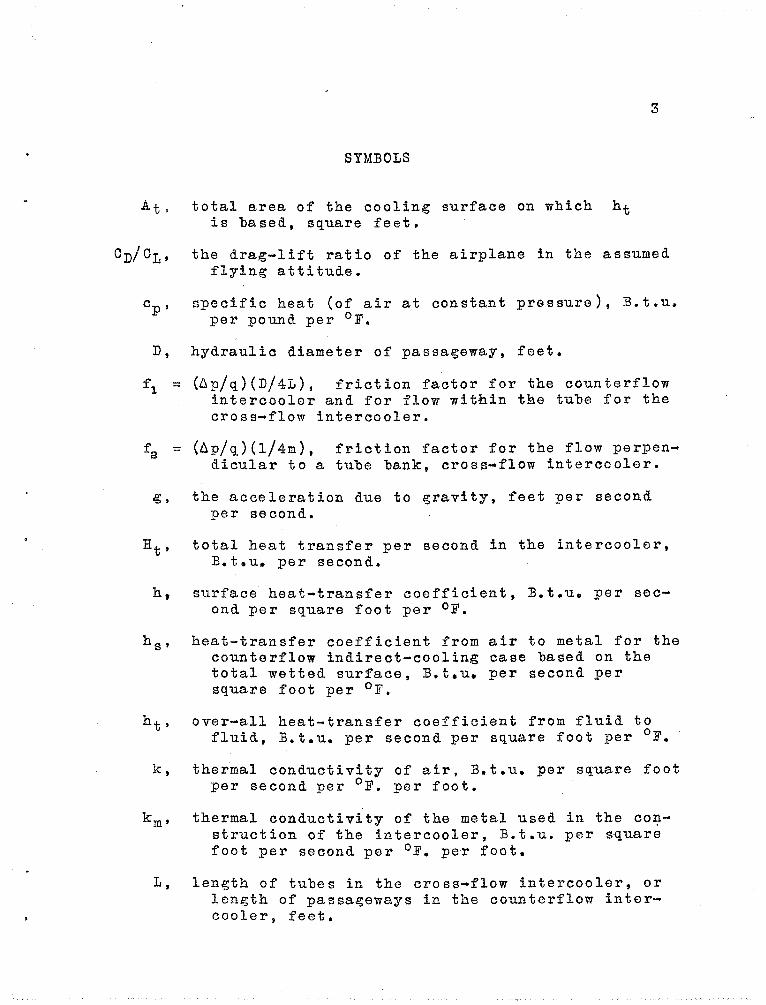
SYMBOLS
A t , t o t a l a r e a o f t h e c o o l i n g s u r f a c e on which h t i s b a s e d , square f e e t .
cD/cL, t h e d r a g - l i f t r a t i o of t h e a i r p l a n e i n t h e assumed f l y i n g a t t i t u d e .
c P ' s p e c i f i c h e a t (of a i r a t c o n s t a n t p r e s s u r e ) , B.t.u. p e r pound p e r O F .
D , h y d r a u l i c d i a m e t e r of passapeway, f e e t .
fl = ( 4 p l q ) ( ~ / 4 ~ ) , f r i c t i o n f a c t o r f o r t h e c o u n t e r f l o w i n t e r c o o l e r and f o r f low w i t h i n t h e tube f o r t h e c ross - f low i n t e r c o o l e r .
fa = ( d p / q ) ( l / 4 m ) , f r i c t i o n f a c t o r f o r t h e f l o w perpen- d i c u l a r t o a t u b e bank, c ross - f low i n t e r c o o l o r .
g , t h e a c c e l e r a t i o n due t o g r a v i t y , f e e t p e r second p e r second ,
H t , t o t a l h e a t t r a n s f e r p e r second i n t h e i n t e r c o o l e r , B.t.u, p e r second.
h , s u r f a c e h e a t - t r a n s f e r c o e f f i c i e n t , 3.t .u. p e r sec- ond p e r square f o o t p e r OF.
h s , h e a t - t r a n s f e r c o e f f i c i e n t from a i r t o me ta l f o r t h e c o u n t e r f l o w i n d i r e c t - c o o l i n g c a s e based on t h e t o t a l w e t t e d s u r f a c e , B.t.u. p e r second p e r square f o o t p e r O F .
h t , o v e r - a l l h e a t - t r a n s f e r c o e f f i c i e n t from f l u i d t o f l u i d , B.t.u. p e r second p e r s q u a r e f o o t p e r O F ,
k , t he rmal c o n d u c t i v i t y of a i r , 3.t .u. p e r s q u a r e f o o t p e r second p e r OF. p e r f o o t .
k,, the rmal c o n d u c t i v i t y of t h e me ta l used i n t h e con- s t r u c t i o n of t h e i n t e r c o o l e r , B.t.u. p e r s q u a r e f o o t p e r second p e r OF. p e r f o o t ,
L, l e n g t h of t u b e s i n t h o c ross - f low i n t e r c o o l e r , o r l e n g t h of passageways i n t h e c o u n t e r f l o w i n t e r - c o o l e r , f e e t .
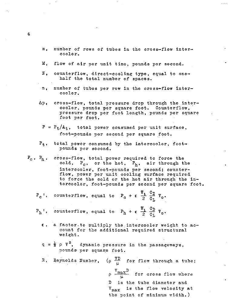
m , number o f rows of t u b e s i n t h o cross- f low i n t e r - c o o l e r .
M , f low of a i r p e r u n i t t i m e , pounds p o r second.
N, c o u n t e r f l o m , d i r e c t - c o o l i n g t y p e , e q u a l t o one- h a l f t h e t o t a l number o f spaces .
n , number o f t u b e s p e r row i n t h e c r o s s * f l o a i n t e r - c o o l e r .
Ap, c r o s s - f l o w , t o t a l p r e s s u r e d r o p th rough t h e i n t e r - cooXer, pounds p e r square f o o t . Counter f low, p r e s s u r e d rop p e r f o o t l e n g t h , pounds p e r s q u a r e f o o t p e r f o o t .
P = Pt/At, t o t a l power consumed p e r u n i t s u r f a c e , foot-pounds p e r second p e r s q u a r e f o o t .
P t , t o t a l power consumed by t h s i n t e r c o o l e r , f o o t - pounds p e r second.
PC, %, c r o s s - f l o w , t o t a l p o n e r r e q u i r e d t o f o r c e t h e c o l d , P C o r t h e h o t , Ph, a i r t h r o u g h t h e i n t e r c o o l e r , foot -pounds p e r second; c o u n t e r - f l o w , power por u n i t c o o l i n g s u r f a c e r e q u i r e d t o f o r c e t h e c o l d o r t h e h o t a i r th rough t h e i n - t e r c o o l e r , foot-pounds p e r second p e r s q u a r e f o o t ,
m, CD PC I , c o u n t e r f l o w , e q u a l t o PC + € -- -- 2 cL To'
c o u n t e r f l o w , e q u a l
t: , a f a c t o r , t o m u l t i p l y t h e f n t e r c o o l e r weight t o ac- count f o r t h e a d d i t i o n a l r e q u i r e d s t r u c t u r a l w e i g h t ,
q = p va , dynamic p r e s s u r e i n t h e yassagemays, pounds per squar-e f o o t .
TD f o r f l o n th rouqh a t u b e ; R , ~ e y n o l d s lumber . (p - -
f o r c r o s s f l o n where -7-- D i s t h e t u b e d i a m e t e r and Vmax i s the f l o n v e l o c i t y a t t h e q o i n t of minimum w i d t h . )

s p a c i n g , a s shown i n f i g u r e s l ( a ) and l ( b ) , f e e t ; and i n f i g u r e 2 , t u b e d i a m e t e r s .
t e m p e r a t u r e of t h e h o t a i r , OF..
t e m p e r a t u r e of t h e c o l d a i r , OF.
a i r - f l o w v e l o c i t y th rough t h e i n t e r c o o l e r , f e e t p e r second.
f l i g h t v e l o c i t y of t h e a i r p l a n e , f e e t p e r second.
r ~ i d t h of f i n ; o r s p a c e r , f e e t , a s shown i n f i g u r e 1.
t o t a l weight of t h e i n t e r c o o l e r , pounds.
W1 = w/At, t o t a l weight p e r u n i t s u r f a c e , pounds p e r square f o o t .
tm, t h i c k n e s s of me ta l between ho t and c o l d f l u i d s , f e e t .
pV, mass flom of c o l d o r h o t a i r p e r second p e r s q u a r e f o o t o f open a r e a , s l u g s p e r s q u a r e f o o t p e r second.
p V g , weight f lom of c o l d o r h o t a i r p e r second p e r s q u a r e f o o t of open a r e a , pounds p e r square f o o t p e r second.
, c o e f f i c i e n t o f v i s c o s i t y of a i r , s l u g s p e r foot -second,
np, pump e f f i c i e n c y : f o r t h e h e a t e d - a i r s i d e , e q u a l t o t h e compressor e f f i c i e n c y ; f o r t h e ' c o o l i n g - a i r s i d e , e q u a l t o t h e r a t f o sf t h e i n t e r n a l work done ( V p ) t o t h e c o r r e s p o n d i n g i n c r e a s e i n d r a g mu- l t ip l iod by t h e f l i g h t v e l o c i t y ( v O A D ) .
t f , f i n t h i c k n e s s , f e e t .
p , mass d e n s i t y of a i r , s l u g s p e r c u b i c f o o t .
P m , s p e c i f i c weight of t h e meta l used i n t h e c o n s t r u c t i o n of t h e i n t e r c o o l e r , pounds p e r c u b i c f o o t .
T i - To r e l a t e s t o charge a i r .
T 1 - T . t 'q = -9 ----- 2- ; r e l a t e s t o c o o l i n q Gir. T i - Ti 1
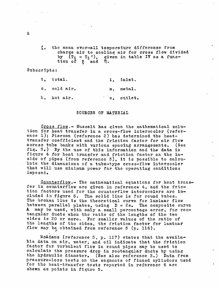
4 , t h e mean ave r - a l l temperature d i f f e r e n c e from c h a r ~ e a i r t o c o o l i n g a i r f o r c r o s s f low d i v i d e d by (Ti w T i ' ) 9 g iven i n t a b l e IV as a func- t i o n of g an& q.
S u b s c r i p t s :
t , t o t a l . i , i n l e t .
C , co ld a i r . m , metal .
h, hot a i r . 6, o u t l e t ,
SOURCES OF MATERIAL
Cross f l m . - Nussel t h a s g iven t h e mathematical solu- t i o n f o r hea t t r a n s f e r i n a cross-f low i n t e r c o o l e r ( r e f e r - ence 1 ) ; P i e r son ( r e f e r e n c e 2 ) has determined the hea t - t r a n s f e r c o e f f i c i e n t and t h e f r i c t i o n f a c t o r f o r a i r f low a c r o s s tube banks w i th v a r i o u s spacing arrangements. (See f i g . 3,) By tho use of t h i s informat ion and the d a t a i n f i ~ u r e 4 f o r h e a t t r a n s f e r and f r i c t i o n f a c t o r on t h e in- s i d e o f p i p e s (from re f e r ence 3 ) , i t i s p o s s i b l e t o ca lcu- l a t e t h e dimensions o f a tube-type cross-f low i n t e r c o o l e r t h a t w i l l use minimum power f o r t h e o p e r a t i n g c o n d i t i o n s imposed,
Counterflow.- The mathematical equa t ions f o r h e a t t r ans - f e r i n counterf low a r e given i n r e f e r e n c e 4 , and t h e f r i c - t i o n f a c t o r s usod f o r t h e counterf low i n t e r c o o l e r s a r e in- c luded i n f i g u r e 5, The s o l i d l i n e i s fox round tubes . The broken l i n e i s the t h e o r e t i c a l curve f o r l aminar f low between p a r a l l e l p l a t e s , u s i n g D = 2s, The composite curve A may 3% used , w i th only a small percen tage e r r o r , f o r roc- t a n g u l a r d u c t s when t h e r a t i o of t h e l e n g t h s of t h e two s i d e s i s 20 o r more. For s m a l l e r va lues of the r a t i o of the l e n g t h s of t h e s i d e s , t h e f r i c t i o n f a c t o r f o r l aminar f low may be, ob t a ined from r e f e r e n c e 5 (p. 116) .
McAdams ( r e f e r e n c e 5 , p. 117) s t a t e s t h a t t h e a v a i l a - b l e d a t a on a i r , wate r , and o i l i n d i c a t e t h a t t he f r i c t i o n f a c t o r f o r t u r b u l e n t f low i n round p i p e s may be used t o ca l cuZa te t h e p r e s s u r e drop i n r e c t a n g u l a r duc t s by u s i n g tho h y d r a u l i c diameter . (See a l s o r e f e r ence 3 . ) Data from p r e s s u r e - l o s s t e s t s on t he segments of f i n n e d c y l i n a e r s usod f o r t h e h e a t - t r a n s f e r t e s t s r e p o r t e d i n re fe ronce 6 a r e shown as p o i n t s i n f i q u r c 5,

The f r i c t i o n f a c t o r f o r t u r b u l e n t flom b e i n g t h e same f o r round as f o r r e c t a n g u l a r d u c t s , i t f o l l o w s from Reynolds a n a l o g y t h a t t h e h e a t - t r a n s f e r c o e f f i c i e n t i s t h e sane i n b o t h k i n d s of tube . The same a n a l o g y i n d i c a t e s t h a t , f o r l a m i q a r f low, t h e r e c t a n g u l a r d u c t s shou ld have a h e a t - t r a n s f e r c o e f f i c i e n t somewhat h i g h e r t h a n t h a t o f a round tube . The h e a t - t r a n s f e r d a t a f o r round t u b e s ( f i g . 4 ) were used f o r both c o u n t e r f l o ~ v i n t e r c o o l e r s aecause no h e a t - t r a n s f e r d a t a f o r l aminar f low th rough r e c t a n g u l a r d u c t s x were a v a f l a b l e .
DESIGX CONDITIONS
In t h e d e s i g n of a n i n t e r c o o l e r , t h e r e a r e known: t h e mass flom of h o t a i r t h r o u g h t h e i n t e r c o o l e r , t h e tem- p e r a t u r e s a t which t h e h a t a n d t h e c o l d a i r e n t e r t h e in- t e r c o o l e r , and t h e t e m p e r a t u r e a t mhich t h e h o t a i r i s re- q u i r e d t o l e a v e t h e i n t e r c o o l e r .
In o r d e r t o des3.qn t h e i n t e r c o o l e r t h a t a i l1 uso l e a s t power, t i le f l i s h t v e l o c i t y , t h e d r a g - l i f t r a t i o of t h e air- p l a n e f o r t h i s v i s c o s i t y , a n d t h e f a c t o r c must be knonn t o o b t a i n t h e power used i n t r a n s p o r t i n g t h e i n t e r c o o l e r we igh t . I n a d d i t i o n , t h e pumping e f f i c i e n c i e s must be knonn i n o r d e r t o c a l c u l a t e t h e t o t a l pumping power charge- a b l e t o t h e i n t e r c o o l e r , a n d t h e a l t i t u d e a t which t h e max- imum demand i s made upon t h e i n t e r c o o l e r ~ u s t Be known i n o r d e r t o de te rmine t h e f l u i d c o n s t a n t s of t h e c o o l i n g a i r .
For t h e purposw o f d s m o n s t r a t i n g t h e method of d e s i q n u s e d i n t h i s i n v e s t i g a t i o n : t h e f o l l o w i n g c o n d i t i o n s a r e assumed:
1. The b r a k e horsepower of t h e e n s i n e i s 1 ,000.
2, The cng ine u s e s 6 ,600 pounds of a i r p e r h o u r , o r 1.833 pounds p e r second.
4. Thc a i r p l a n e i s o p e r a t i n g a t t h e r a t e d h e i g h t of t h e e n g i n e , which i s 25,000 f e e t .
5. To, t h e f l i g h t v e l o c i t y of t h e a i r p l a n e , i s 300 m i l e s p e r hour o r 440 f e e t p o r second.
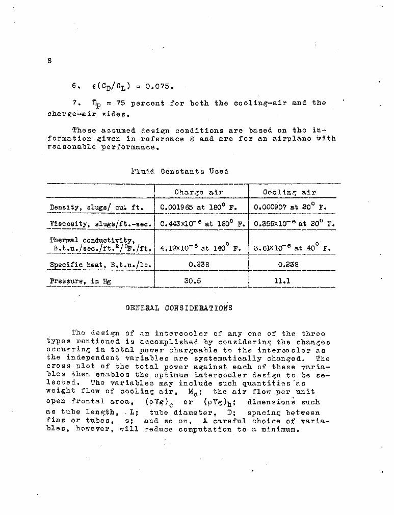
7 . % = 75 p e r c e n t f o r b o t h t he c o o l i n g - a i r and t h e
c h a r g e - a i r s i d e s ,
2hcse assumed d e s i q n c o n d i t i o n s a r e based on t h e i n - f o r m a t i o n gfvon i n r e f e r e n c e 8 and a r e f o r a n a i r p l a n e w i t h r e a s o n a b l e performance.
F l u i d Constant s Used --------------- --__-_--.---- ----- -----I--------
! Chareo a i r T c o o l i n e s i r
Density, slugs/ cui f t . 10.001965at 180°F . 0.000907at 20°F. -------_I----------- ---------__------ --&--.-.-I------ 4 I- Viscosity, slugs/ft at 180' F. 0 .355~10-~ at 20' F. ----------I------- ------------ -------em---- -I- Thermal conductivity, 1 ~.t.u./sec./ft,~/~./ft.~.l9~10-~ at 140' F. 3.61~10-' at 40' F.
-------.-------l-__l_ --..--------..--- ----------------- I i
Specific heat, ~ , t .u./lb. I I-------- --I---- .-
0.238 0.238 +---------------- --------------- 1
Pressure, i n Hg i 30.5 -----------------.-----A - - C I - - C I - - - - - - . - - - - I
GEBERAL CONSIDERATIONS
Tho d c s i g n of an i n t e r c o o l e r of any one of the t h r e e t y p e s mentioned i s accompl ished by considering t h e changes o c c u r r i n g i n t o t a l power c h a r g o a b l e t o t h e i n t e r c o o l e r a s t h e independent v a r i a b l e s a r e s y s t e m a t i c a l l y changed. The c r o s s p l o t o f t h e t o t s f power s q a i n s t each of t h e s e v a r i a - b l e s then e n a b l e s t h e optimum i n t e r c o o l e r d e s i q n t o be se- l e c t e d . The v a r i a b l e s may i n c l u d e such q u a n t i t i e s 'as weight f low of c o o l i n g a i r , Mc: t h e a i r f low p e r u n i t open f r o n t a l a r e a , ( p ~ g ) , o r ( p ~ g ) h : dimensions such as t u b 9 l e n g t h , .L; tube d i a m e t e r , D; spac ing between f i n s o r t u b e s , s; and so on. A c a r e f u l cho ice o f v a r i a - b l e s , however, m i l l r educe computa t ion t o a minimum,
COUNTERFLOF IN'J!ERCOOLER
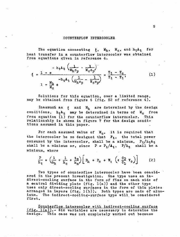
The e q u a t i o n c o n n e c t i n g e, Hh, M c , and h t A t f o r h e a t t r a n s f e r i n a coun te r f low i n t e r c o o l e r w a s o b t a i n e d from e q u a t i o n s g i v e n i n r e f e r e n c e 4.
5 = ---------------- - A V
T i - T i '
Mh 1 - ; ; - e Mcc "d = ---
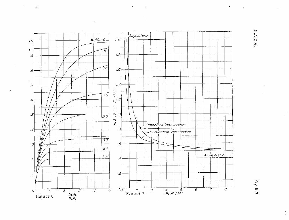
S o l u t i o n s f o r t h i s e q u a t i o n , over a l i m i t e d r a n g e , may be o b t a i n e d from f i g u r e 6 ( f i g . 52 of r e f e r e n c e 4 ) .
Inasmuch as % and Mh a r e de termined by t h e d e s i g n c o n d i t i o n s , htAt may be de terminod i n t e rms of from from e q u a t i o n (1) f o r t h e c o u n t e r f l o w i n t e r c o o l e r . T h i s r e l a t i o n s h i p i s shown i n f i g u r e 7 f o r t h e d e s i g n condi- t i o n s assumed i n t h i s p a p e r .
For e a c h assumed v a l u e of Me, i t i s r e q u i r e d t h a t t h e i n t e r c o o l e r be so d e s i g n e d t h a t P t , t h e t o t a l power consumed by t h e i n t e r c o o l e r , s h a l l be a minimum, pt/htAt s h a l l be a minimum o r , s i n c e P c Pt/Atr P/ht s h a l l be a minimum, where
Two t y p e s o f coun te r f low i n t e r c o o l e r have been cons id- e r e d i n t h e p r e s e n t i n v e s t i g a t i o n . One type u s e s an i n - d i r e c t - c o o l i n g s u r f a c e i n t h e form o f f i n s on each s i d e of a c e n t r a l d i v i d i n g p l a t e ( f i g , l ( a ) ) a n d t h e o t h e r type u s e s o n l y d i r e c t - c o o l i n g s u r f a c e s i n t h e form of t h i n p l a t a s a r r a n g e d i n l a y e r s ( f i g , I ( % ) ) , Both t y p e s a r e mado o f alum- inum. The i n d i s e c t - c o o l i n g - s u r f a c e type w i l l be c o n s i d e r e d f i,r s t .
Counterf low i n t e r ~ o o l e a mi th i n d i r e c t - c o o l i x s u r f a c e -------.-....--- ---------------------- ------- J a g . ~(all.- S i x v a r i a b l e s a r e n e c e s s a r y t o de te rmine t h e d e s i g n . T h i s c a s e w a s n o t comple te ly worked o u t because

t h e l a r g e number of v a r i a b l e s meant a v e r y l a r g e number of d e s i q n s t o be c a l c u l a t e d . Accord ing ly , t h e problem was s i m p l i f i e d by assuming t h e f i n wid th and spac ing t o be i d e n t i c a l f o r b o t h s i d e s of t h e i n t e r c o o l e r . The v a r i a b l e s s e l e c t e d were ( P V ~ ) ~ , ( P V ~ ) ~ , f i n s p a c i n g , and f i n width. The advan tage i n s e l e c t i n g t h e weight f l o w o f a i r p e r u n i t open f r o n t a l a r e a ( p ~ g ) ~ and (pVg)h, i n p r e f e r e n c e t o
i n t e r c o o l e r d imensions such as l e n g t h , i s t h a t t h e r e s u l t - i n g c a l c u l a t i o n s a r e somewhat more s t r a i g h t f o r w a r d .
Table I o u t l i n e s t h e c a l c u l a t i o n s f o r t h e d e s i g n of a c o u n t e r f l o w i n t e r c o o l e r w i t h i n d i r e c t - c o o l i n g s u r f a c e . Tar- i o u s s i m p l i f i c a t i o n s a r e p o s s i b l e o a i n q t o t h e r e p e t i t i o n s encoun te red . These s i m p l i f i c a t i o n s a r e no ted benea th t h e t a b l e and r e s u l t i n a d e c r e a s e of more t h a n t h r e e - f o u r t h s of t h e i n d i c a t e d c a l c u l a t i o n s . The f i n w i d t h s u s e d i n t h e c a l c u l a t i o n s mere 0.0417, 0.0833, and 0,1666 f o o t w i t h f i n s p a c i n ~ of 0.0042, 0.0083, 0.0208, and 0.0416 f o o t f o r each f i n w i d t h used. The q u a n t i t i e s ( ~ v G ) ~ and ( P V ~ ) ~ were e i v e n v a l u e s of 1, 4 , 7 , and 10.
Tho h y d r a u l i c d i a m e t e r , D = -5!ZiJT-- can be c a l c u l a t e d 2 ( s+m) '
f o r a n y g iven f i n spac ing and midth; t h e n Reynolds Number, VD R = e-- P ' can be c a l c u l a t e d f o r any v a l u e o f pV. A f t e r
t h e Reynolds Number i s known, Nusso l t Is number, h s ~ / k , and hence h s , can be o b t a i n e d from f i g . 4 . The q u a n t i t y
h s i s t h e s u r f a c e h e a t - t r a n s f e r c o e f f i c i e n t between a i r and s u r f a c e i n a r e c t a n g u l a r channel of s e c t i o n s by w f e e t .
The f o r n u l a f o r t 3 e h e a t - t r a n s f e r c o e f f i c i e n t based on u n i t a r e a of t h e d i v i d i n g p l a t e f o r such a f i n n e d c o o l b i n g s u r f a c e i s
t a n h a w f '"t hh ( o r h c ) = s + t f k a w * i'
tv 1 = v + t f / 2 and a = Ji lhs/ tm t f
L ----- , number of f i n s p e r u n i t w i d t h of d i v i d i n g s+ t p l a t e .
( 2 tan-h-a~.? 1 , e q u i v a l e n t c o o l i n g a r e a 0 5 one a m t
f i n of u n i t l e n g t h i f t h e e n t i r e e q u i v a l e n t a r e a i s assumed t o be a t base t e m p e r a t u r e .
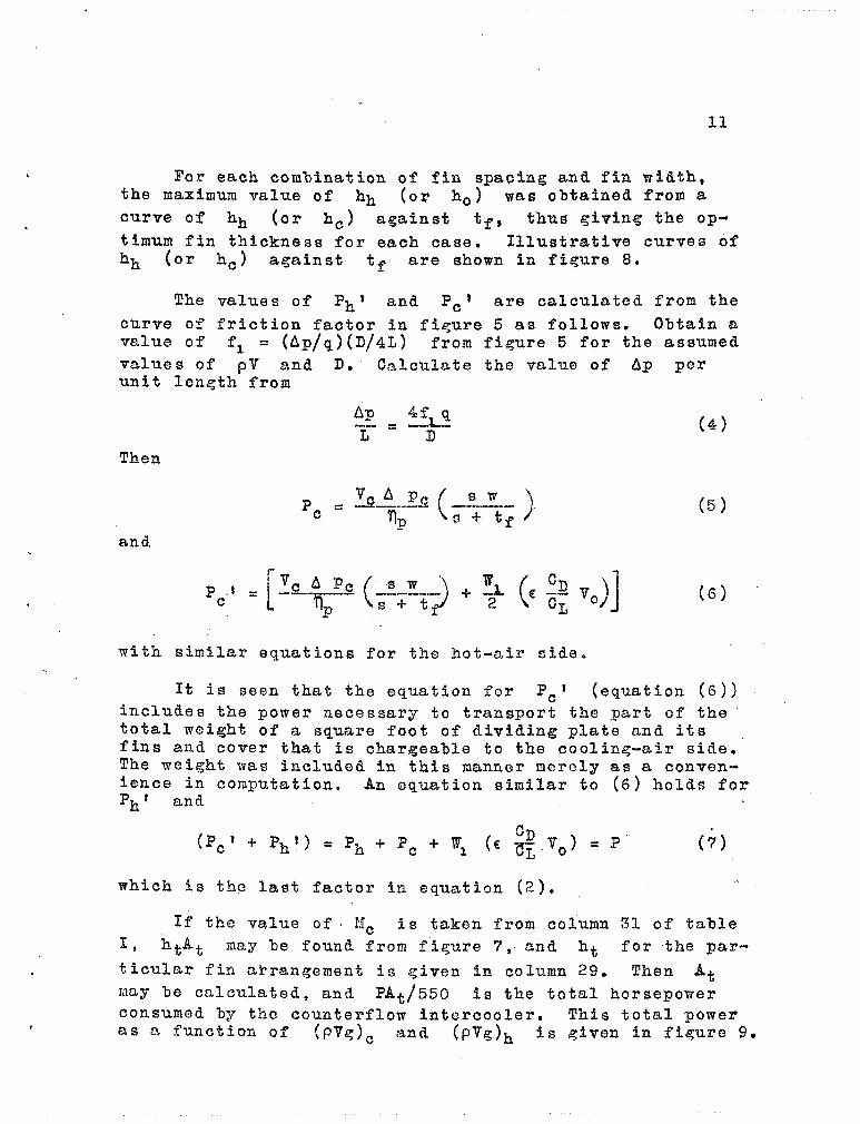
For each combinat ion of fin s p a c i n g and f i n width, t h e maximum v a l u e of hh ( o r h o ) w a s o b t a i n e d from a c u r v e o f hh ( o r he ) a g a i n s t E f , t h u s g i v i n g t h e op- t i m u m f i n t h i c k n e s s f o r each case . I l l u s t r a t f v e c u r v e s of hh ( o r h e ) a g a i n s t t f a r e shown i n f i g u r e 8.
The v a l u e s of P h * and PC a r e c a l c u l a t e d from t h e curve of f r i c t i o n f a c t o r i n f i g u r e 5 as fo l lows . Obta in a v a l u e of f , = ( A p / 9 ) ( ~ / 4 ~ ) f r o n f i g u r e 5 f o r t h e assumed v a l u e s of p V a n d D. C a l c u l a t e t h e v a l u e o f Ap p e r u n i t l o n q t h from
Then
and
with similar e q u a t i o n s f o r t h e h o t - a i r s i d e .
I t i s seen t h a t t h e e q u a t i o n f o r P C t ( e q u a t i o n ( 6 ) ) i n c l u d e s t h e pomex n e c e s s a r y t o t r a n s p o r t t h e p a r t o f t h e . t o t a l weight of a square f o o t of d i v i d i n g p l a t e and i t s f i n s and cover t h a t i s c h a r g e a b l e t o t h e c o o l i n g - a i r s i d e . The we igh t mas i n c l u d o d i n t h i s mannor meroly as a conven- i e n c e i n computa t ion , An e q u a t i o n similar t o ( 6 ) h o l d s f o r P h f and
which i s t h o l a s t f a c t o r I n e q u a t i o n ( 2 ) .
I f t h e v a l u e o f I.lc i s t a k e n from column 3 1 o f t a b l e I , htAt may be found from f i c u r e 7 , a n d h t f o r t h e par- t i c u l a r f i n akrangement i s q i v e n i n column 29. Then At may be c n l c u l a t e d , and pAt/550 i s t h e t o t a l horsepower consumed by t h e coun te r f low i n t e r c o o l e r . Th i s t o t a l power a s a f u n c t i o n of ( p ~ q ) , a n d ( P V ~ ) ~ i s g iven i n f i q u r e 9.

The s m a l l e s t power consumption c a l c u l a t e d f o r t h i s type of i n t e r c o o l e r w a s abou t 1 6 horsepower. Th i s power c o u l d p r o b a b l y be f u r t h e r reduced by u s i n g a l a r g e r i n t e r - c o o l e r and n s m a l l e r a i r v e l o c i t y th rough t h e i n t e r c o o l e r , 1% i s l a t e r shown ( s e e t a b l e vI) t h a t a n i n t e r c o o l e r of t h i s t y p e , which u s e d 16 horsepower, w a s abou t as l a r g e as c o u l d r e a s o n a b l y be used, I f t h i s i n t e r c o o l e r were u s e d i n n cross - f low i n s t e a d of a c o u n t e r f l o w t y p e , t h e mean t e m p e r a t u r e d i f f e r e n c e a v a i l a b l e f o r c o o l i n g would be abou t 20 p e r c e n t s m a l l e r ; a c o r r e s p o n d i n s i n c r e a s e of a b o u t 20 p e r c e n t i n c o o l i n g a r e a , and hence i n power consumed, would t h e r e f o r e be r e q u i r e d ,
Counterf low i n t e r c o o l e r w i t h d i r e c t - c o o l i n e s u r f a c e -------------_-I___----- _^ _--_I.--- - - -----
( f i g . 1 ( b ) 1.- Four v a r i a b l e s a r e n e c e s s a r y t o de te rmine t h e d e s i g n : (pVgIh, (pYg),, sh , and sc. In a l l c a l - c u l a t i o n s made on t h i s type of i n t e r c o o l e r , t h e s p a c i n g s s h a n d sc a r e assumed t o be equal . Table I1 shows t h e c a l c u l a t i o n s r e q u i r e d f o r t h e case of t h e cou&erf low i n t e r - c o o l e r w i t h d i r e c t - c o o l i n g s u r f a c e . R e p e t i t i o n s s imf ls r t o t h o s e o c c u r r i n g i n t a b l e I reduce t h o i n d i c a t e d work t o abou t one-four th . I t i s advan tageous , from c o n s i d e r a t i o n s of weight and h e a t f ldw th rough t h e m e t a l , t o have t h e in- d i v i d u a l me ta l p l a t e s as t h i n as p o s s i b l e . A t h i c k n e s s t h a t seemed r e a s o n a b l e (0.0025 f t , ) was s e l e c t e d and spac- i n g s of 0.0021, 0.0042, 0 ,0062, and 0,0083 f o o t were inves- t i g a t e d , The q u a n t i t i e s (pVg)h and ( p ~ g ) ~ were g i v e n v a l u e s of 1, 4 , 7, and 10.
4 The c a l c u l a t i o n f o r t h i s type of i n t e r c o o l e r i s s i m i -
l a r t o that f o r t h e c o u n t e r f l o w i n t e r c o o l e r w i t h i n d i r e c t - c o o l i n q s u r f a c e , excep t f o r t h e c a l c u l a t i o n of P and h t , which a r e now based on t h e t o t a l h e a t - t r a n s f e r s u r f a c e . For t h i s type i n t e r c o o l e r , D = 2 s .
P i c u r e 1 0 shows t h e r e s u l t s o b t a i n e d w i t h t h e d i r e c t - c o o l i n g - s u r f a c e t y p e of i n t e r c o o l e r . The s m a l l e s t s p a c i n g u s e d (0,0021 f t . ) g i v e s a n i n t e r c o o l e r t h a t w i l l consume a b o u t 1 3 horsepower , u s i n q v a l u e s of ( P V ~ ) ~ and (pPg lh between 1 and 2. T h i s power consumption might be reduced t o a b o u t 8 horsepower if t h e weight r e r e seduced by u s i n g 0.000417-foot me ta l i n p l a c e of t h e 0,0025-foot m e t a l u s e d i n t h i s c a l c u l a t i o n . I t seems p r a c t i c a l l y impossible t o u s e such t h i n m e t a l i n a n i n t e r c o o l e r of t h i s type.

THE CROSS-FLOW IMTERCOOLER
The r e q u i r e d h e a t - t r a n s f e r and f r i c t i o n d a t a t o compute t h e case of the cross-flow i n t e r c o o l e r a r e shown i n f i g - u r e s 3 and 4. It may be no ted t h a t , f o r t he flom perpen- d i c u l a r t o a tube bank ( f i g . 3 ) , t he Nusse l t number was found to, be independent. of t ha s p a c i n e f o r a l l the c a s e s where t h o spacing between tubes i n a row equaled t h e spac- i n g between rows ( r e f e r e n c ~ 2) . For the p re sen t des ign , on ly ca ses I n which t h e s e spac ings a r e equal v i l l be con- s ide red . Five v a r i a b l e s a r e neces sa ry t o determine the desigxi, For t h i s cane, t he i n t e r c o o l e r dimensions a r e se- l e c t e d as t h o v a r i a b l e f a c t o r s . These dimensions a r e t h e tube l eng th , t h e tube d iameter , tho spac ing between the t u b e s , the number of t ubes pe r row, and the number of rows of tubes . (See f i g . 2 , )
' , . Tho procedure used i n t h e c a l c u l a t f o n s f o r t h e cross-
f l o m i n t e r c a o l e r .may be most e a s i l y fol lowed by r e f e r e n c e t o t a b l e 111, which i s a sample c a l c u l a t i o n f o r an i n t e r - c o o l e r wi th tube's 2 f e e t l ong and 1/48 . f o o t i n diameter . *
As a p re l imina ry s t e p , f i g u r e 11 (which i s sf v a l u e . i n o b t a i n i n g column 9 of t a b l e 111) i s de r ived a s fol loms:
I , f o r a crdss-flow i n t e r c o o l e r , t he q h a a t i t y of hea t
t r a n s f e r r e d p e r second i s given ( r e f e r e n c e '1) asd . Ht = Mdcp ( T ~ - T o ) = htAt f (Ti - T i ' ) ( 8 ) -
A f t e r a ranqe of va lues of Mc ha s been assumed and and have been c a l c u l a t e d from t h e i r d e f i n i t i o n s , may be read d i r e c t l y from t a b l e I V ( t a b l e 3 of r e f e r -
ence 1 ) . Thus, from equa t ion (%) , a value of htAt may be ob ta ined f o r each assumed value of Mc; a curve of these i s g iven i n f i g u r e 7,

TABLE IV
V a r i a t i o n of 5 w i t h 7) and f
( f rom r e f e r e n c e 1, t a b l e 3 )
For a g i v e n tube l e n ~ t h and d i a m e t e r , such as i s as- sumed i n t h t s c a l c u l a t i o n , t h e v a r i a t i o n of l / h , w i t h ( p ~ ) , ( f i g . 11) i s r e a d i l y c a l c u l a t e d from t h e h e a t - t r a n s f e r d a t a of f i ~ u r e 4 f o r t h e i n s i d e of t h e tube . The curve t h u s o b t a i n e d h o l d s f o r any number of tubes .
F o r any ei'ven number of t u b e s and weight f low on t h e c o l d s i d e , 1 , A t , and Az a r e known and ht, can be c a l c u l a t e d by u s e of f i g u r e 7. hen ( P V ) ~ can be ca lcu- l a t e d from t h e e q u a t i o n

a n d t h e v a r i a t i o n of l / h t w i t h ( P V ) ~ f o r s e v e r a l v a l u e s o f (mn) may t h e r e f o r e be o b t a i n e d ( f i g . 1 1 ) .
The d a t a c o n t a i n e d i n f i q u r e 11, o b t a i n e d i n t h e f o r e - g o i n g manner, mere used f o r t h e c a l c u l a t i o n s i n t a b l e 111, where L and D were h e l d c o n s t a n t and a s e r i e s of v a l - u e s of m , n , a n d s mere assumed.
The r e s u l t s of t h i s sample c a l c u l a t i o n a r e p r e s e n t e d i n f i g u r e s 12 a n d 13. I t may be seen from t h e s e f i g u r e s t h a t t h e minimum power consumption c a l c u l a t e d i s a b o u t 1 0 horsepower. If t h i s power c a l c u l a t i o n i s r e p a a t o d f o r d i f f e r e n t l e n g t h s and d i a m e t e r s of t u b i n g and t h e r e s u l t s a r e c r o s s - p l o t t e d , t h e b e s t combinat ion of t h e f i v e i n t e r - c o o l e r v a r i a b l e s and t h e mass flom of c o o l i n g a i r w i l l be o b t a i n e d .
DISCUSS I O N OF THE RESULTS
The c u r v e s g i v e n i n f i g u r e 7 showing htAt a g a i n s t 1 a r e t h e r e s u l t of a mathemat ica l a n a l y s i s and w i l l ap- p l y t o any c o n c e i v a b l e type o f cross-f low o r coun te r f lom i n t e r c o o l e r t h a t i s t o meet t h e d e s i g n c o n d i t i o n s . T h i s f i g u r e shows t h a t any i n t e r c o o l e r w i t h t h e same v a l u e s of f r i c t i o n f a c t o r and h e a t - t r a n s f e r c o e f f i c i e n t f o r a l l d i r e c - t i o n s of ,air f lom, such as t h e i n t e r c o o l e r shown i n f i g u r e l ( b ) , w i l l be s m a l l e r , hence l i g h t e r and more e f f i c i e n t , if t h e a i r i s i n c o u n t e r f l o w than if i t i s i n c r o s s f lom. The c o u n t e r f l o w i n t e r c o o l e r h a s a b o u t a 20-percent advan- t a q e over t h e cross- f low i n t e r c o o l e r under t h e o p e r a t i n g c o n d i t i o n s chosen f o r t h i s a n a l y s i s .
The f o r e g o i n g c o n s i d e r a t i o n s mould seem t o i n d i c a t e t h a t t h e b e s t method of b u i l d i n g a n i n t e r c o o l e r i s t o make i t o f t h e coun te r f lom . t y p e . Tho assumpt ion of e q u a l f r i c - t i o n f a c t o r and h e a t - t r a n s f e r c o e f f i c i e n t f o r b o t h c r o s s f lom and coun to r f low, however, does n o t h o l d , as can be seen from f ig . sces 3 and 4 .
L
The q u e s t i o n remains whether f low a c z o s s a bank of t u b e s i s more o r l e s s e f f i c i e n t than f low p a r a l l e l t o a t u b e s u r f a c e . A c c o r d i n g l y , c a l c u l a t i o n s mere made f o r sev- e r a l t y p e s of s i m p l i f i e d h e a t exchangers f o r t h e p u r p o s e of comparing t h e optimum d e s i g n s f o r each type u n d e r t h e same o p e r a t i n g c o n d i t i o n s . Table V e i v e s t h e r e s u l t s o f t h e s e c a l c u l a t i o n s , The f o l l o w i n g p o i n t s should be no ted :

( a ) Much h i ~ h e r h e a t d i s s i p a t i o n p e r square f o o t of c o o l i n g s u r f a c e i s a c h i e v e d i n c r o s s f low. That i s , much l e s s me ta l s u r f a c e i s r e q u i r e d f o r e q u a l amounts o f h e a t d i s s i p a t i o n ,
( b ) Cool ing e f f i c i e n c i e s a r e comparable f o r f low w i t h i n t u b e s a n d f o r f low a c r o s s a t u b e bundle .
TABLE V
A Conparison of Optimum Beat-Exchanger Des igns f o r A i r Flow w i t h i n a n d a c r o s s a Tube Bundle
( np = 25.6 i b . / s q . f t . : e n e r g y d i n s i p a t - e d , 250 hp.: "'T.? - Tia = 70° F.; Qp = 100 p e r c e n t ; a i r - m e t a l h e a t - t r a n s f e r
coefficient t a k o n e q u a l t o h t )
I H e a t dissi- I Required pat ion per f ronta l
Cesign t y p e I unit cooling area surface
A i r flow within
= 1/48 f t .
Length (or deptha of design
A i r flow within hexagonal tubes, D = 1/48 f t . t 51
Cooling efficiency heat dissipated i
A i r f low across round tubes.,
I D = 1/48 f t , s = 1/96 f t , I .98
I
-
PPumping power cost
I 12.2. 1 .31
5
,
')T, i s t h e t e m p e r a t u r e of t h e m e t a l s u r f a c e s and i s as- sumed t o be c o n s t a n t th roughou t t h e h e a t exchanger , s i n c e w a t e r i s on t h e o t h e r s i d e o f t h e h e a t - t r a n s f e r s u r f a c e .
b ) ~ u m p i n g power c o s t i s o n l y t h e power r e q u i r e d t o push t h e air t h rough ; the qower u s e & i n pumping v a t o r i s n o t c o n s i d e r e d .
22.8
Air flow across round tubes; D = 1 / 4 8 f t . 1 s"=: 1/48 f t . .74 9.80 1 .92
i

The c a l c u l a t i o n s i n t a b l e V show t h a t t h e cross-flow tube-type hea t exchanger overcomes i t s i n i t i a l d isadvantage of lower mean-temperature d i f f e r e n c e by d i s s i p a t i n g more h e a t p e r u n i t a r e a owing t o a h ighe r h e a t - t r a n s f e r c o e f f i - c i e n t . The r a t i o of hea t t r a n s f e r t o pumping power i s about the same f o r f low e i t h e r w i t h i n o r a c r o s s t he tubes . The s m a l l e r coo l ing a r e a r e q u i r e d by the cross-flow tube-type h e a t exchanger w i l l t hus r e s u l t i n a cons iderab ly l i g h t e r i n t e r c o o l e r , This advantage of weight-saving i s enough t o evercome the 20-percent d isadvantage i n mean temperature difference and t o g ive an i n t e r c o o l e r r e q u i r i n g l e s s t o t a l power,.
I t i s of i n t e r e s t t o no te t h a t t he power l o s s i n t he duct between t h e supercharger and the i n t e r c o o l e r b e a r s t he same r a t i o t o t h e powsr less through the h o t - a i r s i d e of t h e i n t e r c o o l s r as the p ra s su ro drep i n tho duct b e a r s t o t h e p re s su re drop through the i n t e r c o o l e r . An e s t i m a t e sf t h e power l a s s i n t he duc t can be made by use of t he Ba- mer ica l r e s u l t s i n t he sameple c s l c u l a t i o n s , the p r e s s u r e drop i n the duct having been measursd.
Altheugh t h e c a l c u l a t i o n s f o r t he t h r e o types of i n t e r - c a o l a r s show the tube-type crass-flew hn te rcoo le r t o be su- p e r i o r on tho basi4s of t o t a l power requf.r@d, t o t a l power may no t bs the on ly cons ide ra t ion . Table V I shows t h a t t he power censumcad by the i n t e r c o s l a r v a r i e s between about 10 and 25 horsepower i n the b e s t des igns c a l c u l a t e d f o r t h e t h r e e t ypes of i n t e r c o o l e r considtarad. Whather t h e a c t u a l power consumption i s 10 o r 25 horsepower f o r a 1,000-horse- powsr engine, i s not n a c e s s a r i l y t he determining cons ider - a t i o n i n t h e @he ice of an i n t e r c o o l e r , Ruggedness of con- s t r u c t i e n , easc o f i n s t a l l a t i o n , f r o n t a l s r e a , OF l e n g t h might e a s i l y be t h e dec id ing f a c t o r when t he d i f f e r e n a e i n t o t a l pomw i s s o small.
Obviously, any ind i r ec t - coo l ing arrangement can be i m - proved by the s u b s t i t u t i o n of a d i r ec t - coo l ing su r f ace f o r an i n d i r e c t - c o o l i n g su r f ace , The r equ i r ed cool ing s u r f a c e i s t h u s reduced which, i n t u r n , reduces the weight and t h e power t o pump t h e a i r through t h e exchanger.
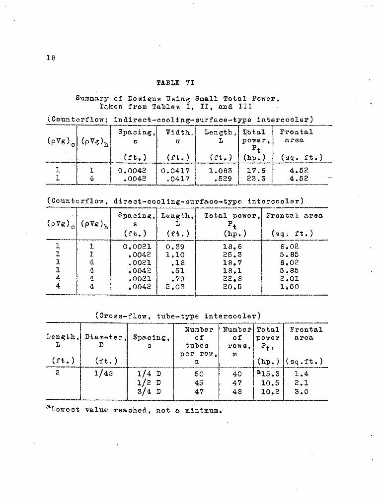
TABLE V I
Summary of Designs Using Small Total Power, Taken f r o m Tables I, 11, and 111
<Counte~flovr; indirect-cooling-surface-type intercooler) - - - - C - - ~ - l - - - - - - - - - - - - - - - - - - - - - - I - - - - - - - - - C - - - -
(Counterflow, direct-cooling-surface-type intercooler) ---- I------ T'--------r------- r - - - - r---------- I Spacing, Length, Potol power, s j *t
(ft.1 I (hp. )
Frontal area
(sq. ft*) ------------- 8.02 5,85 8.02 5.85 2.01 1m50
(Cross-flow, tube-type intercooler)
L tubes
2 47 10.5 2,1
47 3 * 0
a ~ o w e s t value reached, not a minimum.
CONCLUDIWG REMARKS
The r e s u l t s show the importance of u s ing the i n t e r - c o o l e r having optimum dimensions f o r tho ope ra t ing condi- t i o n s spec i f i ed . They f u r t h e r show t h e r e l a t i v e power c o s t a s s o c i a t e d w i t h pumping the coo l ing and the charge a i r through the i n t e r c o o l e r and the power t o t r a n s p o r t the i n t e r c o o l e r . The r e l a t i v e importance of t he v a r i o u s di - mensions of the i n t e r c o o l e r i s a l s o e a s i l y determined by an examination o f t h e t a b l e s and the f i g u r e s .
The t o t a l power t o ope ra t e a well-desisned i n t e r - c o o l e r i s so small t h a t o t h e r c o n s i d e r a t i o n s , such a s ea se of i n s t a l l a t i o n o r r u ~ g e d n e s s o f c o n s t ~ u c t i o n , might e a s i l y be t h e determining cons ide ra t ion i n t h e choice of a type of i n t e r c o o l e r .
Langleg Memorial Aeronaut ica l Laboratory, Nat iona l Advisory Committee f o r Aeronaut ics ,
Langleg F i e l d , V a . , May 26; 1939.
REFEREM OES
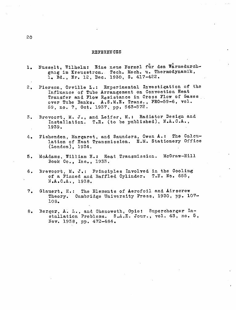
N u s s g l t , Wilhelm: E ine neue Formel f k r den ~ k r m e d u r c h - gaag i m Xreuzstrom. Tech. Mech, u. Thermodynamik, 1. Bd., N r . 1 2 , Dec. 1930 , So 417-422.
P i e r s o n , O r v i l l e L. : Exper imenta l I n v e s t i g a t i o n of t h e I n f l u e n c e of Tube Arrangement on Convect ion Heat T r a n s f e r a n d Flow R e s i s t a n c e i n Cross Flow o f Gases over Tube Banks. A,S.M.E, T r a n s . , PRO-59-6, vo l . 5 9 , no. 7 , Oct. 1937, pp , 563-572.
B r e v o o r t , U. J , , a r d L e i f e r , M . : R a d i a t o r Design a n d I n s t a l l a t i o n . T.R. ( t o be ~ u b l i s h e d ) , N.A*C.A. , 1939.
F i shenden , H a r g a r e t , a n d Saunders , Omen A. : The Calcu- l a t i o n of Heat Transmiss ion . H.14. S t a t i o n e r y Off i c e ondo don) , 1934.
McAdams , V i l l i a m H. : Heat Transmiss ion . McGraw-Hill Book Co., Inc. , 1933.
B r e v o o r t , M, 3. : P r Z n c i p l e s Involved i n t h e Cool ing o f a Finned and B a f f l e d Cyl inder . T*N, W O , 655, N,A+C*Ae, 1938,
G l a u e r t , 3,: The Elements of A e r o f o i l and Ai r sc rew Theory. Cambridge U n i v e r s i t y P r e s s , 1930, pp, 107- 108,
B e r g e r , A. L., and Chenoweth, Opie t Supercharger In- s t a l l a t i o n Problems. S.A.E. Jour . , v o l . 4 3 , no* 5, NOT. 1938, pp* 4'724!84r

FIGURE LEGENDS
( a ) Fin-type counterf low i n t e r c o o l e r . ( b ) Countorflow i n t o r c o o l e r w i th d i r e c t coo l inq surfaces.
F i g m e 1.- Lay-out dimensions of tvo counterflom typos of i n t e r c o o l e r .
F igure 2,- Tube lay-out dimensions of a cross-flow typo of i n t e r c o o l e r .
F igure 3.- Var i a t i on of Mu.sselt number h ~ / k and f r i c t i o n .
LJ? 1 f a c t o r -- - with Reynolds Number D ~ v ~ ~ ~ / I J ~ f o r a i r s 4m
flom a c r o s s tube banks ( r e f e r e n c e 2).
Figure 4.- Var i a t i on of Musselt number h ~ / k and f r i c t i o n
f a c t o r 42 a with Reynolds Number ~ p V / p f o r a i r flow q 4.L
through c i r c u l a r t ubes ( r e f e r e n c e 3 ) ,
Figure 5.- Var ia t ion o f f r i c t i o n f a c t o r 42 2 q 4L
mith
Reynolds Number D p ~ / y f o r f u l l y developed a i r flow through c i r c u l a r and r e c t a n g u l a r tubes .
F igure 6.- ~ r a ~ h i c a i p r e s e n t a t i o n of s o l u t i o n s t o equa t ion ( I ) ( 'eferoncc 4 ) .
Xigure 7.- Required va lues of h e a t - t r a n s f e r c o e f f i c i e n f and coo l ing s u r f a c e . a s a f u n c t i o n of t h e mass flom of cool- i n g air f o r c r o s s f l o v and f o r counterf low i n t e r c n o l e r s . 4 , 0.645; M h , 1.833 lb. /sec,
Ffgure 8.- I l l u s t r a t i o n of t h e method of u s i n 5 equa t ion ( 3 ) t o determine the optimum f i n t h i c k n e s s f o r a f i n - t ype coun te r f lon i n t e r c o o l e r . Fin wid th , 1/24 f t e ; ( p v d , 10.
T i s u r e 9.- Var ia t ion of t o t a l horsepower consumed mi th ( p ~ g ) , and ( P V ~ ) ~ f o r a f in- type coun te r f lon i n t c r - cooler .
(a) Spacing, 0,0083 f t . ( b ) Spacing, 0,0063 f t . ( c ) Spacing, 0.0042 f t . ( d ) Spacing, 0,0021 f t ,
F igu re 10.- Va r i a t i on of horseponer consumed wi th (pvgIc f o r sovc ra l v a l u e s of ( p ~ g ) h and spao&g i n a d i r e c t - cool ing-surface counterflom i n t e r c o o l e r .
F igu re 11.- Var i a t i on of l / h t and l / h c wi th ( P V ) C in a tubo-type cross-flom i n t e r c o o l e r ,
F i g u r e 12,- V a r i a t i o n of horsepower consumed w i t h m for s e v e r a l v a l u e s of n and s i n a tuba-typo cross- f low i n t e r c o o l e r ,
F i g u r e 13.- V a r i a t i o n of horaepomor coasumod w i t h n f o r s e v e r a l v a l u e s of s p a c i n g , and w i t h s p a c i n g f o r s e v e r a l v a l u e s o f n i n a tube- type cross-f low i n t e r c o o l e r .
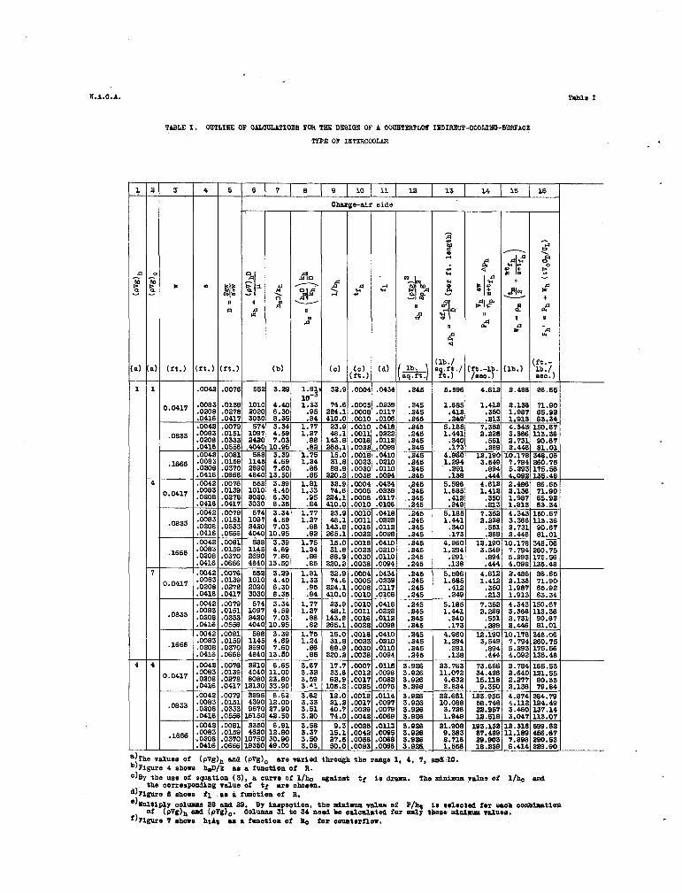
Table I
TABLE I. OUTLIE OF OALOULATI0118 FOR TBe DEBIGE OF A OOWTEWLO+l IWIREOT-000LIBTQ-SUWAOE
TYPE OF IUT&RCCOLEX
he values of ( p ~ g ) ~ and ( P V ~ ) ~ are varied through the range 1, 4, 7, d N). b)~igure 4 shore h,D/k am a funotion of R. O ) B ~ the use of equation (31, a curre of l/ha againat tf is dram. The ainZnmn vdue of l/ho and
the corresponding value of tf are ohosen. d)Figure 5 shore f1 a. a funbtion of R. e)ltultiply column8 a8 and 29. By inspeotion, the uinimo vslao of P/% il melsoted for aaoh ool~binsti~n
of ( p ~ g ) ~ and (pvg),. oolumne 31 to 34 need be crloulatsd for only these aininum values. f)~igure 7 mhore htAt as r funotion of for oomrterflcr.
~a 3 4 5 6 7 8 9 1 0 1 1 la 1s 14 15 16
Ohnrge-air aide
fi
4
7
4
o.0417
.0833
.1666
o.0417
.0833
.1666
.0048 -0083 .0208 .0416 -0042 .0083 .O208 .0416 .0042 .0083 .0206 . o m .0042 .0083 .0208 .0416
.0042
.0083 -0808 -0416 .ooa .0083 .0208 . o m .W42 .0083 .0208 .0416
.0081
.0159
.0370
.OW6
.0076
.0139
.0278
.0417
.0079
.oi51
.0333
. o m
.0081
.0159
.0370
.ow6
.0076
.0139
.0878
.0417
.0079
.0151
.0333
.05s
.0081
.0159
.0370
.0666
588 1145 26d0 4840 558 1010 2020 3030 574 1097 2420 4040 588 1145 2690 4840
2810 4040 8080 12120 ha95 4390 9670 16150 2350 4620 10750 19350
3.39 4.69 7.60 13.50 3.29 4.40 6.30 8.35 3.34 4.59 7.03 10.95 3.39 4.69 7.60 13.50
6.65 11.00 23.80 33.90 s.sa 12 .OO 27.80 4a. 50 6.91 18.80 30.90 49.00
1.75 1.24
.86
.85 1.81 1.33 .95 .64
1.77 1.27 .88 .a2
1.75 1.24 .86 .a5
3.67 3.32 3.59 3.A: 3.62 3.33 3.51 3 .ao 3.58 3.37 3.50 3.08,
15.0 31.8 88.9 220.2 32.9 74.6 224.1 410.0 23.9 48.1 143.8 865.1 15.0 31.8 88.9 aao.2
17.7 33.6 62.9 105.2 1a.o 21 .2 40.7 74.0 9.3 15.1 37.5 80.0
.0018
.0023
.W30
.0038
.0004
.0005
.0008
.0010
.0010
.oozi
.0016
.ooaa
.0018 ,0023 .0030 .oars .0007 .0012 .0017 .0085 .ooia .0017 .0029 .oo4a .0025 .0042 .0058 .0083
.0410 ,0210 .0110 .0084 .0434 .0239 .0117 .0106 .0418 .oaza .0112 .ooss .04%0 .0210 -0110 .oos4
.OX15
.0098
.Oil82
.0075
.olir
.0097
.0079
.ooea
.0113
.OW5
.m8
.OM6
.a45
.245 -245 .a45 .a45 .a45 .245 .a45 .245 .245 .a45 245 .a45 .a45 .a45 .a45
3.936 3.926 3.926 3.296 3.9a5 3.926 3.9a6 3.926 3.986 3.986 3.926 3.9%
4.960 1.294 .291 .I38 5.596 1.685 .412 .a49
5.185 1.441 .340 .i7s
4.960 1.294 ,291 .is8
23.763 11.073 4.633 2.824 aa.661 10.088 3.726 1.949 a1.908 9.383 3.716 1.556
1 m 9 0 3.549 .894 .444 4.612 1.412 .350 .213 7.352 a.aaa .551 .ass
18.190 3.549 .894 .444
73.666 34.436 15.118 9.350
la3.965 58.748 2a.957 za.518 193.138 87.499 a8.903 18.239
10.178 7.794 5.293 4.b2 2.486 2.138 1.987 1.913 4.343 3.366 2.731 a . 4 ~ 10.178 7.794 5.293 4.092
a.784 2.640 2.277 2.136 4.874 4.112 3.460 3.047 18.318 11.189 7.898 6.414
348.06 260.75 175.56 135.48 86.65 71.90 65.92 63.34 150.67 11~.36 90.67 81.01 348.06 360.75 175.56 135.48
166.53 M1.55 90.33 79.84 ~84.79 194.49 137.14 113.07- 599.68 456.67 a80.53 2Z9.90
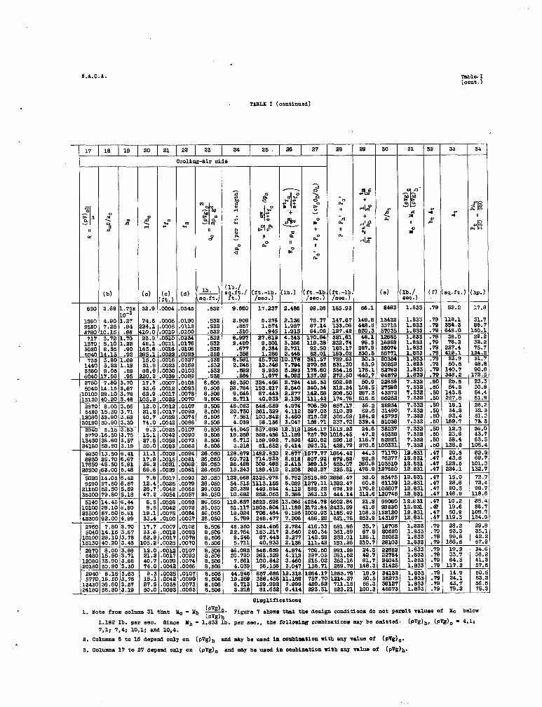
. TABLE I (continued)
1 . Note from oolumn 31 that Yo = Yh Figure 7 shows that the design aondltions do not permit values of Yo below ( P V ~ ) h
1.182 lb. per eeo. Sinae Yh = 1.833 l b . per eeo., the io l lor ing ooinblnations may be omitted: ( P V ~ ) ~ , (PVS)~ 4 , l l 7 , l ; 7,4; 1 0 , l ; and 10,4.
2. Columns 6 t o 16 depend only on (pVgIh and may be ursd in c o m b l ~ t i o n with any valw Of ( P V ~ ) ~ .
3. colunme 17 t o 27 depend only on (pvglo and m y be w e d i n oombi=tion d t h any of (PVS)~.
34
U
(hp.)
17.6
31.7 85.7
150.1 22.2 32.2 75.7
124.2 31.7 48.8 90.5
172.5 23.3 30.8 54.4 81.9 28.2 3 2 3 51.3 7% 3 36.0 43.7 63.3
105.4 62.9 69.7
101.3 132.7
72.7 72.4 98.7
118.5 85.4 86.7
109.7 134.9
29.8 35.1 42.2 57.9 34.6 36.2 41.3 57.5 50.5 53.2 56.5 75.3
33 28 31 32
Cooling-air s ide
..
25
'
- 29
- eP +
P. L* M a '
30 25 17 19
-
P.
( f t . - lb . ( f%.- lb . /sea.)
185.93
147.57 133.06 lZ7.42 321.61 832.74 183.17 163.oa 729.63 531.30 354.18 272.50 502.98 312.24 208.50 174.76 857.17 510.39 305.69 237.72
1512.23 1018.45
596.18 438.79
1664.42 879.82 455.07 325.61
2666.47 1392.47 676.19 444.14
4602.84 2433.59 1185.49
621.76 581.86 361.89 232.91 191.25 991.29 591.52 352.16 269.78
1863.79 1214.37
711.15 523.21
27 23 18 24 20
-
66.1
149.5 448.5 820.3 48.1 96.5
287.9 530.5 30.3 63.9
178.1 '440.7
50.9 108.5 287.3 515.5 36.2 69.6
184.8 339.4 24.6 47.2
116.7 270.5 44.3 92.8
360.8 476.9
32.0 60.8
170.8 312.5 21.8 41.5
108.3 253.9 35.7 67 .5
126.1 210.7
24.3 42.7 81.7
148.3 16.9 30.5 55.3
100.3
c?
21
53
( e l
8483
13422 33718 57035 13685 16868 36074 55771 20364 30252 52762 94579 23656 27598 43273 60252 28934 31490 45795 81038 38237 45338 62821
100331 71170 76277
103510 X27680 83475 81139
105607 120745 99080 98830
122120 143167
18706 80520 28062 28103 22682 22784 24043 31425 34132 35273 38127 46673
22
Le
590
1260 2520 3780 717
1370 3020 5040
735 1440 3360 6040 2750 5040
10100 15130
2870 5480
13080 20180 2940 5770
13430 24180 4830 8830
17550 26500
5020 9590
21150 35300 - 5140
101W 23500 42300
2750
10100 15130
3870 5480
12080 20180
2940 5770
13430 24180
1 n
a m
" irelm 9 4 ir
k PIP + -
(b)
3.58
4.90 7.25
10.15 3.72 5.10 8.35
14.15 3.80 5.22 9.05
17.50 7.60
14.15 29.10 40.20
8.00 15.50 33.90 50.90 8.15
15.50 35.50 58.80 13.50 25.70 45.50 63.00 14.05 27.50 52.50 79.80 14.45 29.10 57.50 92.00
7.80 504014.153.67
29.10 40.20 8.00
15.50 33.90 50.90 8.15
15.50 35.60 58.80
a"
1 eeo.)
1.833
1.833 1.833 1.833 1.633 1.833 1.833 1.833 1.833 1.833 1.833 1.833 7.332 7.332 7.332 7.332 7.332 7.332 7.338 7.332 7.332 7.332 7.332 7.338
M.831 18.831 12.831 12.831 12.831 12.831 12.831 12.831 12.831 12.831 12.831 12.831 1.833 1.833 1.833 1.833 1.833 1.833 1.833 1.833 1.833 1.833 1.833 1.833
1 . 7 5 ~ 1 0 - ~ 1.27
.94
.88 1.70 1.22
.90
.QZ 1.69 1.19
.88
.95 3.70 3.67 3.78 3.48 3.66 3.71 3.56 3.30 3.53 3.75 3.57 3.19 6.41 6.67 5.91 5.46 6.42 6.57 5.69 5,18 5.44 6.50 5.61 4.99 3.70
3.78 3.48 3.56 3.71 3.58 3.30 3.63 3.75 3.57 3.19
( f )
.79
.79
.79
.79
.79
.79 .79 .78 .79 .79 -79 .79 .SO .50 .50 .50 -50 .50 .50 .50 .50 .50 .50 .50 .47 .47 .47 .47 .47 ,47 .47 .47 .47 .47 .47 .47 .79 .79 .79 .79 -79 .79 .79 .79 .79 .79 .79 .79
( o )
32.9
74.6 234.1 410.0
23.9 48.1
143.6 265.1 15.0 31.8 88.9
220.2 17.7 33.6 62.9
105.2 12.0 21.2 40.7 74.0 9 . 3
15.1 27.5 50.0 11.1
- 17.9 36.2 66.6
7.8 12.4 26.7 47 .2
6 . 5 9 . 5
19.1 33.4 17.7 33.6 62.9
105.2 12.0 21.2 40.7 74.0 9 . 3
15.1 2 7 . 5 50.0
(eq.ft .1
52.2
118.1 364.3 648.0
38.0 76.2
227.4 419.1
23.9 50.5
140.7 348.2 25.5 54.3
143.6 257.8 18 .1 34.8 92.4
169.7 12.3 23.8 58.4
135.2 20.8 43.6
122.5 224.1 15.0 28.5 80.3
146.9 10 .2 19.6 50.9
119.3 28.2 53.3 99.6
165.5 19.2 33.7 64.5
117.2 14.9 24.1 43.7 79.2
( a ) ( f t . ) .OW4
.0005
.0008
.0010
.0010
.ooii
.0016
.ooaa .0018 ,0023 .0030 .0038 .0007 .W12 .0017 .0025 .0012 .0017 .0029 .0042 .0025 .0042 .0058 .0083 .0008 .0015 .0021 .Was .0017 .0025 .0042 .0054 -
.0028
.0042
.0075
. a 0 0
.0007
.0012
.OD17
.0025
.0012
.0017
.0029
.0042
.0025
.0042
.0058
.0083
( a )
.0345
.0190
.0112
.0100
.0334
.aim
.0106
.ooss .0327 .Ol68 .0103 .0089 .0108 .0093 .0076 .0070 .0107 .0092 .0074 .0056 .0107 .0090 .0073 .0063 .0094 .0081 .0068 .008l .0093 .0079 .0065 .0057 -
.0093
.0078
.0084 .0037 .0108 .0093 .0078 .0070 .0107 .0092 .0074 .0056 .0107 .0090 .0073 .0063
Ib. s q . f t .
.532
.532
.532
.532
.532
.53a
.532
.ma
.532
.532
.533
.532 8.506 8.508 8.506 8.506 8.506 8.506 8.506 8.506 8.506 8.506 8.506 8.506
26.050 25.050 26.050 26.050 26.050 26.050 25.050 25:050 26.050 26.050 26.050 25.050 8.506 8 . m 8.506 8.506 8.506 8.505 6.506 8.506 8.506 8.506 6.506 8.506
a"
( l b . 1 a q . f t . 1 f t . )
9.660
2.909 .857 .510
8.997 2.480
.577
.356 8.591 2.246
.592 .a84
48.350 22.764 9.546 5.711
46.083 20.730 7.561 4.039
44.945 19.259 5.713 3.218
126.879 60.721 25.488 15.243
122,665 54.53.5 20.339 10.582
119.637 51.117 18.024
5.789 48.350 22.764
9.546 5.711
46.083 20.730
7.561 4.039
44.945 19.259 6 . n 3 3.218
I
L*O
( f t . - lb . /sea.)
17.237
5.276 1.574
.945 27.619
a.301 2.384 1.286
45.702 13.346
3.935 1.977
324.456 153.217
87.443 40.933
545.659 261.329 100.842
58.166 857.588 388.456 159.992
81.552 1482.830 714.933 309.486 189.410
2325.976 1113.155
449.824 252.053
3823.596 1803.604
708.484 248.477 324.456 153.217
67.443 40.933
545.659 251.3'29 100.842
56.156 857.688 388.456 159.992
81.552
2
P
( l b . )
2.486
2.136 1.987 1.913 4.343 3.366 2.731 2 . u
10.178 7.794 5.383 4.092 2.784 8.840 2.277 2.136 4.874 4.112 3.460 3.047
12.318 11.189
7.898 6.414 2.877 2.818 2.415 2.208 5.752 5.029 4.112 3.366
13.W6 11.189 9.196 7 . a 2.784 2.640 2.277 2.1% 4.874 4.112 3.460 3.047
12.318 11.189
7.898 6.414
-0
U
-" P.
/ sea . )
99.28
75.77 67.14 64.08
170.94 119.38
92.50 62.01
381.57 270.55 178.60 137.02 415.33 240.34 142.58 111.42 706.50 397.03 215.02 158.71
1264.17 757.70 420.82 293.31
1577.77 807.92 389.15 262.27
2515.80 1279.31
585.52 363.13
4254.78 2l72.84 1009.93 486.28 416.33 240.34 148.58 111.42 706.50 397.03 215.02 156.71
1264.17 757.70 420.62 293.31

Table I1
TABLE 11. OUTLINE OF CALCULATIOUS FOR TEE DESIGN OF A COUBTERFLOS DIRECT-COOLITIG-SURFACE
TYPE 03" IUTWCWLER
(For simplifications, see Table I)
a)~he values of ( P V ~ ) ~ and ( P V ~ ) ~ are varied through the range 1, 4, 7, and 10, the values of ah aM sC are varied through the range 0.0021, 0.0042, 0.0062, and 0.0083.
b)~igure 4 shows hD/k as a function of R. 01~igure 5 shows fl as a function of R.
TABLE I1 (oontimwd)
Table II (oont.)
d ) ~ ~ inspection, the minimum value of P/ht i~ selected for each combination of ( P V ~ ) ~ and (p~g) , . OolWns 27 to 31 need be oaloulated only for these minimum values.
' )~igure 7 ehora htAt a8 a function of Yo for eounterflm.
TABLE I11
OUTLINE OF CALCULATIONS FOR THE DESIGN OF A TUBE-TYPE CROSS-FLOW INTERCOOLEX
(L = 2 f t , D = 1/48 f t . Subscript 2 refers to charge-air aide.)
- CThe derivation of f ig . 11 l a erplsined i n the Bert. The value of ( ~ ' l ) ~ I s selected oopper tubes, wall thickness 0.005 in., density cf oopper i s 555 lb. per ou. i t . E;
for =uch 1 - + using the proper of 4) and 1 (column 10). e a s i n g of copper, 1/32 in. thickness, seamed to encase the intercooler oompletely.
ht hc hh' hh Ei

N.A.C.A. Figs .l,Z
Figure 1.
of f low
0 0 0 ROW m , n tubes
Figure 2.
N.A.C.A. F
igs ,3,4
Figu re 6. && Mh

N.A.C.A. Figs.8,3


N.A
.C.A
. F
igs .11,12

Related Documents