EC2311-COMMUNICATION ENGINEERING UNIT I ANALOG COMMUNICATION Analog Communication is a data transmitting technique in a format that utilizes continuous signals to transmit data including voice, image, video, electrons etc. An analog signal is a variable signal continuous in both time and amplitude which is generally carried by use of modulation. Analog circuits do not involve quantisation of information unlike the digital circuits and consequently have a primary disadvantage of random variation and signal degradation, particularly resulting in adding noise to the audio or video quality over a distance. Data is represented by physical quantities that are added or removed to alter data. Analog transmission is inexpensive and enables information to be transmitted from point-to-point or from one point to many. Once the data has arrived at the receiving end, it is converted back into digital form so that it can be processed by the receiving computer. Analog communication systems convert (modulate) analog signals into modulated (analog) signals).

Welcome message from author
This document is posted to help you gain knowledge. Please leave a comment to let me know what you think about it! Share it to your friends and learn new things together.
Transcript
EC2311-COMMUNICATION ENGINEERING
UNIT I
ANALOG COMMUNICATION
Analog Communication is a data transmitting technique in a format that utilizes
continuous signals to transmit data including voice, image, video, electrons etc. An
analog signal is a variable signal continuous in both time and amplitude which is
generally carried by use of modulation. Analog circuits do not involve quantisation of
information unlike the digital circuits and consequently have a primary disadvantage of
random variation and signal degradation, particularly resulting in adding noise to the
audio or video quality over a distance.
Data is represented by physical quantities that are added or removed to alter data.
Analog transmission is inexpensive and enables information to be transmitted from point-
to-point or from one point to many. Once the data has arrived at the receiving end, it is
converted back into digital form so that it can be processed by the receiving computer.
Analog communication systems convert (modulate) analog signals into modulated
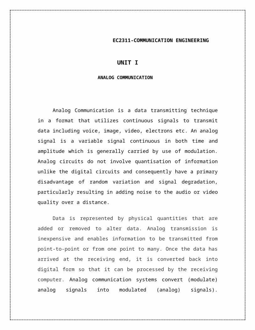
(analog) signals). Communication systems convert information into a format appropriate
for the transmission medium. The Block diagram of a communication system is given
below:
Fig.1 Communication System Block Diagram
The Source encoder converts message into message signal or bits. The
Transmitter converts message signal or bits into format appropriate for channel
transmission (analog/digital signal). The Channel introduces distortion, noise, and
interference. Receiver decodes received signal back to message signal. Source decoder
decodes message signal back into original message.
Amplitude Modulation:
Amplitude modulation (AM) is a technique used in electronic communication,
most commonly for transmitting information via a radio carrier wave. AM works by
varying the strength of the transmitted signal in relation to the information being sent. For
example, changes in the signal strength can be used to specify the sounds to be
reproduced by a loudspeaker, or the light intensity of television pixels. (Contrast this with
frequency modulation, also commonly used for sound transmissions, in which the
frequency is varied; and phase modulation, often used in remote controls, in which the
phase is varied).
In order that a radio signal can carry audio or other information for broadcasting or for
two way radio communication, it must be modulated or changed in some way. Although
there are a number of ways in which a radio signal may be modulated, one of the easiest,
and one of the first methods to be used was to change its amplitude in line with variations
of the sound.
The basic concept surrounding what is amplitude modulation, AM, is quite
straightforward. The amplitude of the signal is changed in line with the instantaneous
intensity of the sound. In this way the radio frequency signal has a representation of the
sound wave superimposed in it. In view of the way the basic signal "carries" the sound or
modulation, the radio frequency signal is often termed the "carrier".
Fig.2 Amplitude Modulation, AM
When a carrier is modulated in any way, further signals are created that carry the actual
modulation information. It is found that when a carrier is amplitude modulated, further
signals are generated above and below the main carrier. To see how this happens, take the
example of a carrier on a frequency of 1 MHz which is modulated by a steady tone of 1
kHz.
The process of modulating a carrier is exactly the same as mixing two signals together,
and as a result both sum and difference frequencies are produced. Therefore when a tone
of 1 kHz is mixed with a carrier of 1 MHz, a "sum" frequency is produced at 1 MHz + 1
kHz, and a difference frequency is produced at 1 MHz - 1 kHz, i.e. 1 kHz above and
below the carrier.

If the steady state tones are replaced with audio like that encountered with speech of
music, these comprise many different frequencies and an audio spectrum with
frequencies over a band of frequencies is seen. When modulated onto the carrier, these
spectra are seen above and below the carrier.
It can be seen that if the top frequency that is modulated onto the carrier is 6 kHz, then
the top spectra will extend to 6 kHz above and below the signal. In other words the
bandwidth occupied by the AM signal is twice the maximum frequency of the signal that
is used to modulated the carrier, i.e. it is twice the bandwidth of the audio signal to be
carried.
In Amplitude Modulation or AM, the carrier signal is given by
It has an amplitude of ‘A’
modulated in proportion to the message bearing (lower frequency) signal
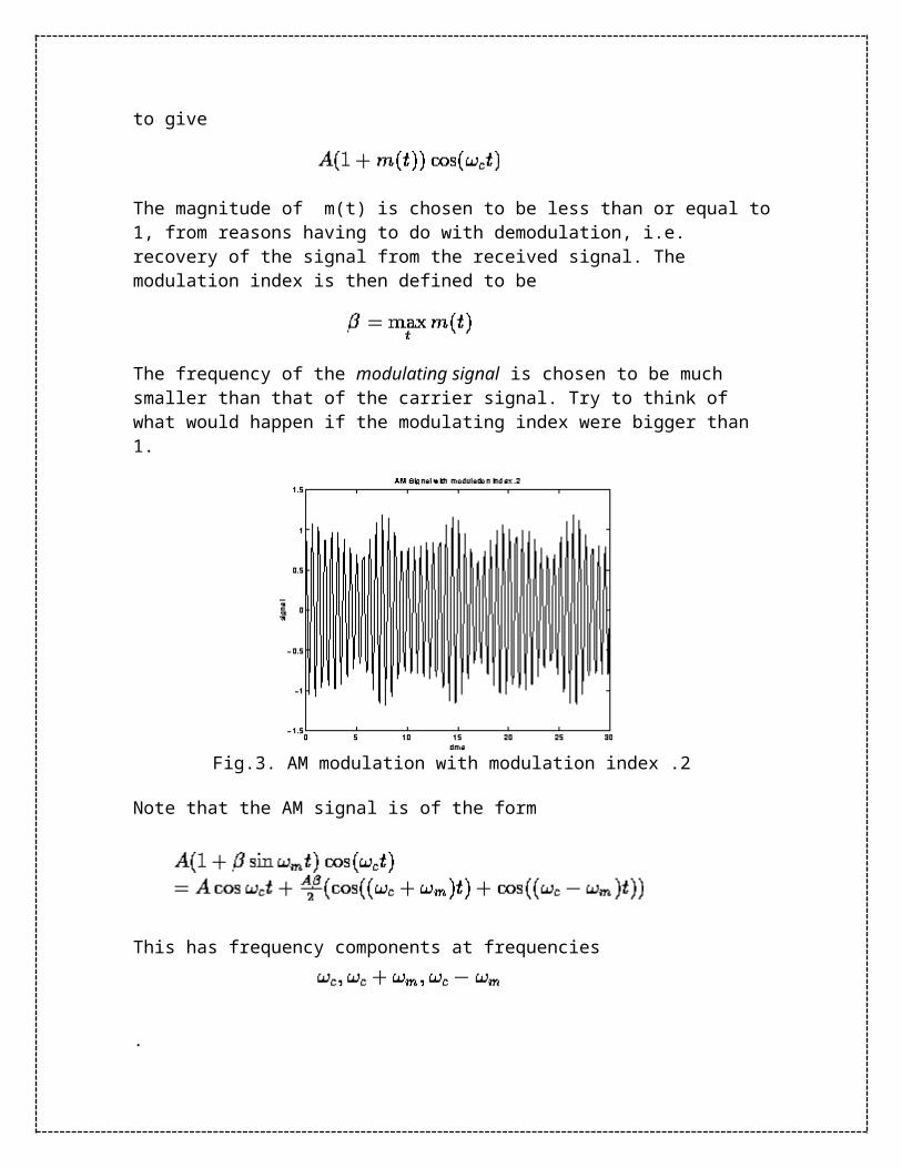
to give
The magnitude of m(t) is chosen to be less than or equal to 1, from reasons having to do with demodulation, i.e. recovery of the signal from the received signal. The modulation index is then defined to be
The frequency of the modulating signal is chosen to be much smaller than that of the carrier signal. Try to think of what would happen if the modulating index were bigger than 1.
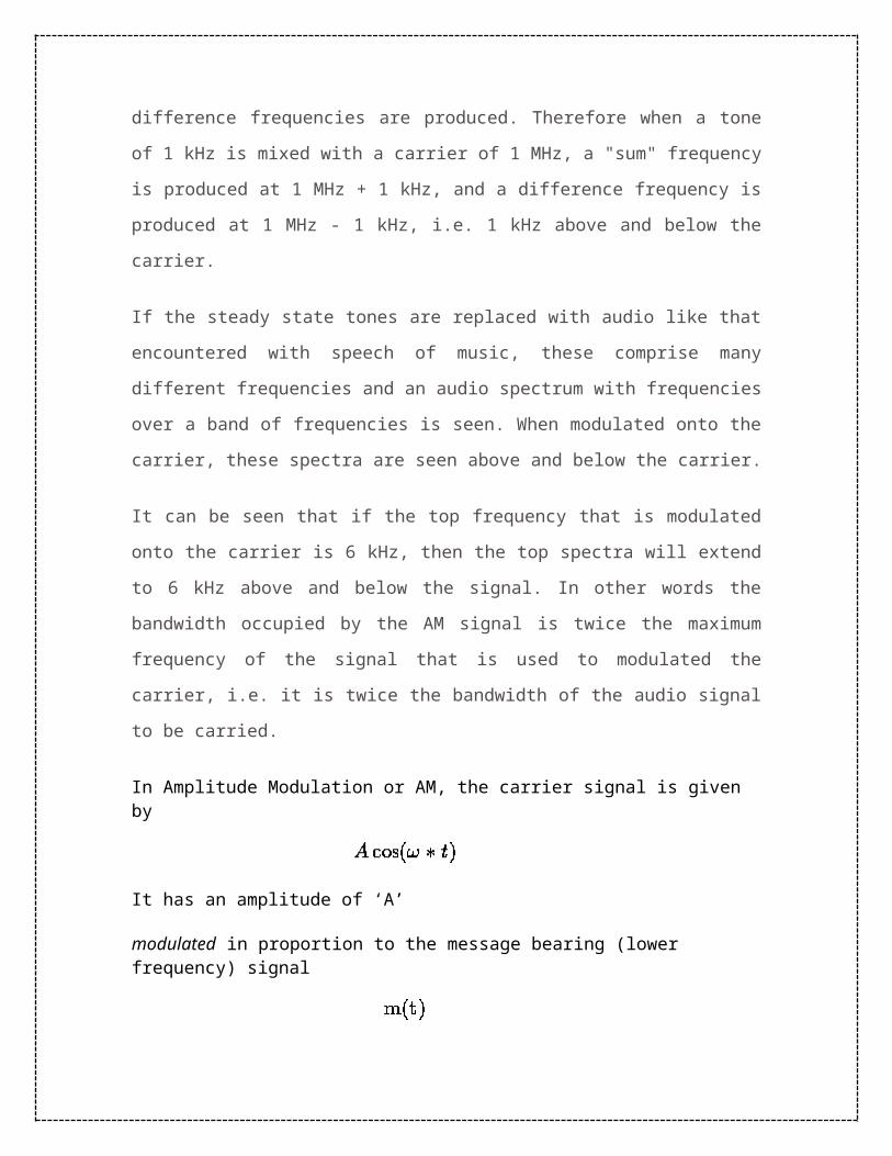
Fig.3. AM modulation with modulation index .2
Note that the AM signal is of the form
This has frequency components at frequencies
.
Fig.4: AM modulation with modulation index .4
The version of AM that we described is called Double Side Band AM or DSBAM since we send signals at both
, and at
It is more efficient to transmit only one of the side bands (so-called Single Side
Band AM or USBAM, LSBAM for upper and lower side bands respectively), or if the
filtering requirements for this are too arduous to send a part of one of the side band. This
is what is done in commercial analog NTSC television, which is known as Vestigial Side
Band AM. The TV video signal has a bandwidth of about 4.25 MHz, but only 1 MHz of
the lower side band of the signal is transmitted. The FCC allocates 6 MHz per channel
(thus 0.75 MHz is left for the sound signal, which is an FM signal (next section)).
You may have wondered how we can listen to AM radio channels on both stereo and
mono receivers. The trick that is used to generate a modulating signal by adding a DSB
version (carrier at 38 Khz suppressed) version of the output of the difference between the
Left and Right channels added to the sum of the Left and Right channels unmodulated.
The resulting modulating signal has a bandwidth of about 60 KHz. A mono receiver gets
the sum signal whereas a stereo receiver separates out the difference as well and
reconstitutes the Left and Right channel outputs.
Amplitude demodulation
Amplitude modulation, AM, is one of the most straightforward ways of
modulating a radio signal or carrier. The process of demodulation, where the audio signal
is removed from the radio carrier in the receiver is also quite simple as well. The easiest
method of achieving amplitude demodulation is to use a simple diode detector. This
consists of just a handful of components:- a diode, resistor and a capacitor.
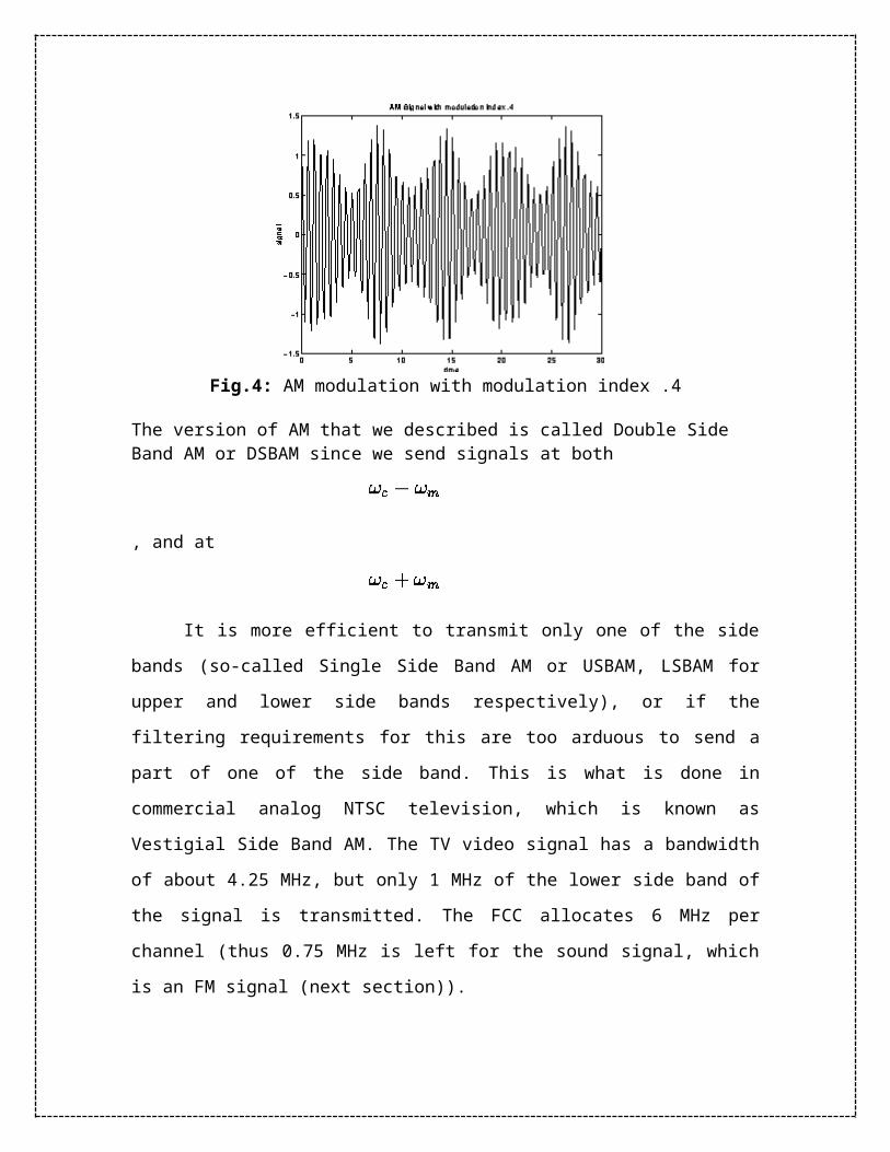
Fig. 5 AM Diode Detector
In this circuit, the diode rectifies the signal, allowing only half of the alternating
waveform through. The capacitor is used to store the charge and provide a smoothed
output from the detector, and also to remove any unwanted radio frequency components.
The resistor is used to enable the capacitor to discharge. If it were not there and no other
load was present, then the charge on the capacitor would not leak away, and the circuit
would reach a peak and remain there.
Advantages of Amplitude Modulation, AM
There are several advantages of amplitude modulation, and some of these reasons have
meant that it is still in widespread use today:
It is simple to implement
it can be demodulated using a circuit consisting of very few components
AM receivers are very cheap as no specialised components are needed.
Disadvantages of amplitude modulation
Amplitude modulation is a very basic form of modulation, and although its simplicity is
one of its major advantages, other more sophisticated systems provide a number of
advantages. Accordingly it is worth looking at some of the disadvantages of amplitude
modulation.

It is not efficient in terms of its power usage
It is not efficient in terms of its use of bandwidth, requiring a bandwidth equal to
twice that of the highest audio frequency
It is prone to high levels of noise because most noise is amplitude based and
obviously AM detectors are sensitive to it.
Thus, AM has advantages of simplicity, but it is not the most efficient mode to use, both
in terms of the amount of space or spectrum it takes up, and the way in which it uses the
power that is transmitted. This is the reason why it is not widely used these days both for
broadcasting and for two way radio communication. Even the long, medium and short
wave broadcasts will ultimately change because of the fact that amplitude modulation,
AM, is subject to much higher levels of noise than are other modes. For the moment, its
simplicity, and its wide usage, mean that it will be difficult to change quickly, and it will
be in use for many years to come.
SINGLE SIDEBAND MODULATION
Single sideband modulation is widely used in the HF portion, or short wave
portion of the radio spectrum for two way radio communication. There are many users of
single sideband modulation. Many users requiring two way radio communication will use
single sideband and they range from marine applications, generally HF point to point
transmissions, military as well as radio amateurs or radio hams.
Single sideband modulation or SSB is derived from amplitude modulation (AM) and SSB
modulation overcomes a number of the disadvantages of AM. Single sideband
modulation is normally used for voice transmission, but technically it can be used for
many other applications where two way radio communication using analogue signals is
required. As a result of its widespread use there are many items of radio communication
equipment designed to use single sideband radio including: SSB receiver, SSB
transmitter and SSB transceiver equipments.
Single sideband, SSB modulation is basically a derivative of amplitude modulation, AM.
By removing some of the components of the ordinary AM signal it is possible to
significantly improve its efficiency.
It is possible to see how an AM signal can be improved by looking at the
spectrum of the signal. When a steady state carrier is modulated with an audio signal, for
example a tone of 1 kHz, then two smaller signals are seen at frequencies 1 kHz above
and below the main carrier. If the steady state tones are replaced with audio like that
encountered with speech of music, these comprise many different frequencies and an
audio spectrum with frequencies over a band of frequencies is seen. When modulated
onto the carrier, these spectra are seen above and below the carrier. It can be seen that if
the top frequency that is modulated onto the carrier is 6 kHz, then the top spectra will
extend to 6 kHz above and below the signal. In other words the bandwidth occupied by
the AM signal is twice the maximum frequency of the signal that is used to modulated the
carrier, i.e. it is twice the bandwidth of the audio signal to be carried. Amplitude
modulation is very inefficient from two points. The first is that it occupies twice the
bandwidth of the maximum audio frequency, and the second is that it is inefficient in
terms of the power used. The carrier is a steady state signal and in itself carries no
information, only providing a reference for the demodulation process. Single sideband
modulation improves the efficiency of the transmission by removing some unnecessary
elements. In the first instance, the carrier is removed - it can be re-introduced in the
receiver, and secondly one sideband is removed - both sidebands are mirror images of
one another and the carry the same information. This leaves only one sideband - hence
the name Single SideBand / SSB.
SSB receiver
While signals that use single sideband modulation are more efficient for two way radio
communication and more effective than ordinary AM, they do require an increased level
of complexity in the receiver. As SSB modulation has the carrier removed, this needs to
be re-introduced in the receiver to be able to reconstitute the original audio. This is
achieved using an internal oscillator called a Beat Frequency Oscillator (BFO) or Carrier
Insertion Oscillator (CIO). This generates a carrier signal that can be mixed with the
incoming SSB signal, thereby enabling the required audio to be recovered in the detector.
Typically the SSB detector itself uses a mixer circuit to combine the SSB modulation and
the BFO signals. This circuit is often called a product detector because (like any RF
mixer) the output is the product of the two inputs.
It is necessary to introduce the carrier using the BFO / CIO on the same frequency
relative to the SSB signal as the original carrier. Any deviation from this will cause the
pitch of the recovered audio to change. Whilst errors of up to about 100 Hz are
acceptable for communications applications including amateur radio, if music is to be
transmitted the carrier must be reintroduced on exactly the correct frequency. This can be
accomplished by transmitting a small amount of carrier, and using circuitry in the
receiver to lock onto this.
There are several types of two way radio communication that it is possible to
listen to legally. Radio amateurs form a large group that short wave listeners can listen to
quite legally, and the transmissions are easy to find as they are all contained within the
amateur radio band allocations - see the section of this website on ham radio. In view of
its popularity it is necessary to know how to tune an SSB signal and receive the SSB
signal in the best way to ensure that the best copy is obtained. Although it is slightly more
difficult to tune than an AM or FM signal, with a little practice, it is easy to become used
to tuning them in. When receiving SSB it is necessary to have a basic understanding of
how a receiver works. Most radio receivers that will be used to receive SSB modulation
will be of the superheterodyne type. Here the incoming signals are converted down to a
fixed intermediate frequency. It is at this stage where the BFO signal is mixed with the
incoming SSB signals. It is necessary to set the BFO to the correct frequency to receive
the form of SSB, either LSB or USB, that is expected. Many radio receivers will have a
switch to select this, other receivers will have a BFO pitch control which effectively
controls the frequency. The BFO needs to be positioned to be in the correct position for
when the signal is in the centre of the receiver passband. This typically means that it will
be on the side of the passband of the receiver. To position the BFO, tune the SSB signal
in for the optimum strength, i.e. ensure it is in the centre of the passband, and then adjust
the BFO frequency for the correct pitch of the signal. Once this has been done, then the
main tuning control of the receiver can be used, and once a signal is audible with the
correct pitch, then it is also in the centre of the receiver passband.
Tuning an SSB signal with the BFO set is quite easy. First set the receiver to the SSB
position or the BFO to ON, and then if there is a separate switch set the LSB / USB
switch to the format that is expected and then gradually tune the receiver. Adjust the main
tuning control so that the pitch is correct, and the signal should be comprehensible. If it is
not possible to distinguish the sounds, then set the LSB / USB switch to the other position
and re-adjust the main tuning control if necessary to return the signal to the correct pitch,
at which point the signal should be understandable.
SSB advantages
Single sideband modulation is often compared to AM, of which it is a derivative. It has
several advantages for two way radio communication that more than outweigh the
additional complexity required in the SSB receiver and SSB transmitter required for its
reception and transmission.
1. As the carrier is not transmitted, this enables a 50% reduction in transmitter power
level for the same level of information carrying signal. [NB for an AM
transmission using 100% modulation, half of the power is used in the carrier and a
total of half the power in the two sideband - each sideband has a quarter of the
power.]
2. As only one sideband is transmitted there is a further reduction in transmitter
power.
3. As only one sideband is transmitted the receiver bandwidth can be reduced by
half. This improves the signal to noise ratio by a factor of two, i.e. 3 dB, because
the narrower bandwidth used will allow through less noise and interference.
Single sideband modulation, SSB is the main modulation format used for analogue voice
transmission for two way radio communication on the HF portion of the radio spectrum.

Its efficiency in terms of spectrum and power when compared to other modes means that
for many years it has been the most effective option to use. Now some forms of digital
voice transmission are being used, but it is unlikely that single sideband will be ousted for
many years as the main format used on these bands.
Frequency Modulation
While changing the amplitude of a radio signal is the most obvious method to modulate
it, it is by no means the only way. It is also possible to change the frequency of a signal to
give frequency modulation or FM. Frequency modulation is widely used on frequencies
above 30 MHz, and it is particularly well known for its use for VHF FM broadcasting.
Although it may not be quite as straightforward as amplitude modulation, nevertheless
frequency modulation, FM, offers some distinct advantages. It is able to provide near
interference free reception, and it was for this reason that it was adopted for the VHF
sound broadcasts. These transmissions could offer high fidelity audio, and for this reason,
frequency modulation is far more popular than the older transmissions on the long,
medium and short wave bands. In addition to its widespread use for high quality audio
broadcasts, FM is also sued for a variety of two way radio communication systems.
Whether for fixed or mobile radio communication systems, or for use in portable
applications, FM is widely used at VHF and above.
To generate a frequency modulated signal, the frequency of the radio carrier is changed
in line with the amplitude of the incoming audio signal.
Fig.5 Frequency Modulation, FM
When the audio signal is modulated onto the radio frequency carrier, the new radio
frequency signal moves up and down in frequency. The amount by which the signal
moves up and down is important. It is known as the deviation and is normally quoted as
the number of kilohertz deviation. As an example the signal may have a deviation of ±3
kHz. In this case the carrier is made to move up and down by 3 kHz.
Broadcast stations in the VHF portion of the frequency spectrum between 88.5 and 108
MHz use large values of deviation, typically ±75 kHz. This is known as wide-band FM
(WBFM). These signals are capable of supporting high quality transmissions, but occupy
a large amount of bandwidth. Usually 200 kHz is allowed for each wide-band FM
transmission. For communications purposes less bandwidth is used. Narrow band FM
(NBFM) often uses deviation figures of around ±3 kHz. It is narrow band FM that is
typically used for two-way radio communication applications. Having a narrower band it
is not able to provide the high quality of the wideband transmissions, but this is not
needed for applications such as mobile radio communication.
Fig. Frequency Modulation
Advantages of frequency modulation, FM
FM is used for a number of reasons and there are several advantages of frequency
modulation. In view of this it is widely used in a number of areas to which it is ideally
suited. Some of the advantages of frequency modulation are noted below:
Resilience to noise: One particular advantage of frequency modulation is its
resilience to signal level variations. The modulation is carried only as variations
in frequency. This means that any signal level variations will not affect the audio
output, provided that the signal does not fall to a level where the receiver cannot
cope. As a result this makes FM ideal for mobile radio communication
applications including more general two-way radio communication or portable
applications where signal levels are likely to vary considerably. The other
advantage of FM is its resilience to noise and interference. It is for this reason that
FM is used for high quality broadcast transmissions.
Easy to apply modulation at a low power stage of the transmitter: Another
advantage of frequency modulation is associated with the transmitters. It is
possible to apply the modulation to a low power stage of the transmitter, and it is
not necessary to use a linear form of amplification to increase the power level of
the signal to its final value.

It is possible to use efficient RF amplifiers with frequency modulated signals:
It is possible to use non-linear RF amplifiers to amplify FM signals in a
transmitter and these are more efficient than the linear ones required for signals
with any amplitude variations (e.g. AM and SSB). This means that for a given
power output, less battery power is required and this makes the use of FM more
viable for portable two-way radio applications.
Applications
Magnetic tape storage
FM is also used at intermediate frequencies by all analog VCR systems, including
VHS, to record both the luminance (black and white)portions of the video signal.
Commonly, the chrome component is recorded as a conventional AM signal, using the
higher-frequency FM signal as bias. FM is the only feasible method of recording the
luminance ("black and white") component of video to and retrieving video from
Magnetic tape without extreme distortion, as video signals have a very large range of
frequency components — from a few hertz to several megahertz, too wide for equalizers
to work with due to electronic noise below −60 dB. FM also keeps the tape at saturation
level, and therefore acts as a form of noise reduction, and a simple limiter can mask
variations in the playback output, and the FM capture effect removes print-through and
pre-echo. A continuous pilot-tone, if added to the signal — as was done on V2000 and
many Hi-band formats — can keep mechanical jitter under control and assist timebase
correction.
These FM systems are unusual in that they have a ratio of carrier to maximum
modulation frequency of less than two; contrast this with FM audio broadcasting where
the ratio is around 10,000. Consider for example a 6 MHz carrier modulated at a 3.5 MHz
rate; by Bessel analysis the first sidebands are on 9.5 and 2.5 MHz, while the second
sidebands are on 13 MHz and −1 MHz. The result is a sideband of reversed phase on
+1 MHz; on demodulation, this results in an unwanted output at 6−1 = 5 MHz. The
system must be designed so that this is at an acceptable level.

Sound
FM is also used at audio frequencies to synthesize sound. This technique, known as FM
synthesis, was popularized by early digital synthesizers and became a standard feature for
several generations of personal computer sound cards.
Radio
Main article: FM broadcasting
Edwin Howard Armstrong (1890–1954) was an American electrical engineer who
invented wideband frequency modulation (FM) radio. He patented the regenerative
circuit in 1914, the superheterodyne receiver in 1918 and the super-regenerative circuit in
1922. He presented his paper: "A Method of Reducing Disturbances in Radio Signaling
by a System of Frequency Modulation", which first described FM radio, before the New
York section of the Institute of Radio Engineers on November 6, 1935. The paper was
published in 1936.
As the name implies, wideband FM (WFM) requires a wider signal bandwidth than
amplitude modulation by an equivalent modulating signal, but this also makes the signal
more robust against noise and interference. Frequency modulation is also more robust
against simple signal amplitude fading phenomena. As a result, FM was chosen as the
modulation standard for high frequency, high fidelity radio transmission: hence the term
"FM radio" (although for many years the BBC called it "VHF radio", because
commercial FM broadcasting uses a well-known part of the VHF band—the FM
broadcast band).
FM receivers employ a special detector for FM signals and exhibit a phenomenon called
capture effect, where the tuner is able to clearly receive the stronger of two stations
being broadcast on the same frequency. Problematically however, frequency drift or lack
of selectivity may cause one station or signal to be suddenly overtaken by another on an
adjacent channel. Frequency drift typically constituted a problem on very old or
inexpensive receivers, while inadequate selectivity may plague any tuner.

An FM signal can also be used to carry a stereo signal: see FM stereo. However, this is
done by using multiplexing and demultiplexing before and after the FM process. The rest
of this article ignores the stereo multiplexing and demultiplexing process used in "stereo
FM", and concentrates on the FM modulation and demodulation process, which is
identical in stereo and mono processes.
A high-efficiency radio-frequency switching amplifier can be used to transmit FM signals
(and other constant-amplitude signals). For a given signal strength (measured at the
receiver antenna), switching amplifiers use less battery power and typically cost less than
a linear amplifier. This gives FM another advantage over other modulation schemes that
require linear amplifiers, such as AM and QAM.
FM is commonly used at VHF radio frequencies for high-fidelity broadcasts of music and
speech (see FM broadcasting). Normal (analog) TV sound is also broadcast using FM. A
narrow band form is used for voice communications in commercial and amateur radio
settings. In broadcast services, where audio fidelity is important, wideband FM is
generally used. In two-way radio, narrowband FM (NBFM) is used to conserve
bandwidth for land mobile radio stations, marine mobile, and many other radio services.

Unit 2
Digital Communication
The transmission of digital data through a digital platform that has the ability to combine
text, audio, graphics, video and data. Digital communication enables data to be
transmitted in an efficient manner through the use of digitally encoded information sent
through data signals. These data signals are easily compressed and, as such, can be
transmitted with accuracy and speed.
Unlike in an analog communications where the continuity of a varying signal can not be
broken, in a digital communication a digital transmission can be broken down into
packets as discrete messages. Transmitting data in discrete messages not only facilitates
the error detection and correction but also enables a greater signal processing capability.
Digital communication has, in large part, replaced analog communication as the ideal
form of transmitting information through computer and mobile technologies.
PHASE MODULATION
Phase modulation (PM) is a form of modulation that represents information as
variations in the instantaneous phase of a carrier wave. Unlike its more popular
counterpart, frequency modulation (FM), PM is not very widely used for radio
transmissions. This is because it tends to require more complex receiving hardware and
there can be ambiguity problems in determining whether, for example, the signal has
changed phase by +180° or -180°.
Phase modulation is also similar to frequency modulation in the number of sidebands that
exist within the modulated wave and the spacing between sidebands. Phase modulation
will also produce an infinite number of sideband frequencies. The spacing between these
sidebands will be equal to the frequency of the modulating signal.
Before looking at phase modulation it is first necessary to look at phase itself. A radio
frequency signal consists of an oscillating carrier in the form of a sine wave is the basis

of the signal. The instantaneous amplitude follows this curve moving positive and then
negative, returning to the start point after one complete cycle - it follows the curve of the
sine wave. This can also be represented by the movement of a point around a circle, the
phase at any given point being the angle between the start point and the point on the
waveform as shown.
Phase modulation works by modulating the phase of the signal, i.e. changing the rate at
which the point moves around the circle. This changes the phase of the signal from what
it would have been if no modulation was applied. In other words the speed of rotation
around the circle is modulated about the mean value. To achieve this it is necessary to
change the frequency of the signal for a short time. In other words when phase
modulation is applied to a signal there are frequency changes and vice versa. Phase and
frequency are inseparably linked as phase is the integral of frequency. Frequency
modulation can be changed to phase modulation by simply adding a CR network to the
modulating signal that integrates the modulating signal. As such the information
regarding sidebands, bandwidth and the like also hold true for phase modulation as they
do for frequency modulation, bearing in mind their relationship.
Forms of phase modulation
Although phase modulation is used for some analogue transmissions, it
is far more widely used as a digital form of modulation where it
switches between different phases. This is known as phase shift
keying, PSK, and there are many flavours of this. It is even possible to
combine phase shift keying and amplitude keying in a form of
modulation known as quadrature amplitude modulation, QAM.
The list below gives some of the forms of phase shift keying that are
used:
PSK - Phase Shift Keying
BPSK - Binary Phase Shift Keying

QPSK - Quadrature Phase Shift Keying
QAM - Quadrature Amplitude Modulation
MSK - Minimum Shift Keying
GMSK - Gaussian filtered Minimum Shift Keying
Phase Shift Keying, PSK, basics
Like any form of shift keying, there are defined states or points that
are used for signalling the data bits. The basic form of binary phase
shift keying is known as Binary Phase Shift Keying (BPSK) or it is
occasionally called Phase Reversal Keying (PRK). A digital signal
alternating between +1 and -1 (or 1 and 0) will create phase reversals,
i.e. 180 degree phase shifts as the data shifts state.
Binary phase shift keying, BPSK
The problem with phase shift keying is that the receiver cannot know the exact phase of
the transmitted signal to determine whether it is in a mark or space condition. This would
not be possible even if the transmitter and receiver clocks were accurately linked because
the path length would determine the exact phase of the received signal. To overcome this
problem PSK systems use a differential method for encoding the data onto the carrier.
This is accomplished, for example, by making a change in phase equal to a one, and no
phase change equal to a zero. Further improvements can be made upon this basic system
and a number of other types of phase shift keying have been developed. One simple
improvement can be made by making a change in phase by 90 degrees in one direction
for a one, and 90 degrees the other way for a zero. This retains the 180 degree phase
reversal between one and zero states, but gives a distinct change for a zero. In a basic
system not using this process it may be possible to loose synchronisation if a long series
of zeros are sent. This is because the phase will not change state for this occurrence.
There are many variations on the basic idea of phase shift keying. Each one has its own
advantages and disadvantages enabling system designers to choose the one most
applicable for any given circumstances. Other common forms include QPSK (Quadrature
phase shift keying) where four phase states are used, each at 90 degrees to the other, 8-
PSK where there are eight states and so forth.
PSK constellation diagrams
It is often convenient to represent a phase shift keyed signal, and sometimes other types
of signal using a phasor or constellation diagram. Using this scheme, the phase of the
signal is represented by the angle around the circle, and the amplitude by the distance
from the origin or centre of the circle. In this way the can be signal resolved into
quadrature components representing the sine or I for In-phase component and the cosine
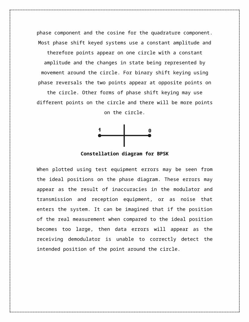
for the quadrature component. Most phase shift keyed systems use a constant amplitude
and therefore points appear on one circle with a constant amplitude and the changes in
state being represented by movement around the circle. For binary shift keying using
phase reversals the two points appear at opposite points on the circle. Other forms of
phase shift keying may use different points on the circle and there will be more points on
the circle.
Constellation diagram for BPSK
When plotted using test equipment errors may be seen from the ideal positions on the
phase diagram. These errors may appear as the result of inaccuracies in the modulator
and transmission and reception equipment, or as noise that enters the system. It can be
imagined that if the position of the real measurement when compared to the ideal position
becomes too large, then data errors will appear as the receiving demodulator is unable to
correctly detect the intended position of the point around the circle.
Constellation diagram for QPSK
Using a constellation view of the signal enables quick fault finding in a system. If the
problem is related to phase, the constellation will spread around the circle. If the problem
is related to magnitude, the constellation will spread off the circle, either towards or away
from the origin. These graphical techniques assist in isolating problems much faster than
when using other techniques.
QPSK is used for the forward link form the base station to the mobile in the IS-95
cellular system and uses the absolute phase position to represent the symbols. There are
four phase decision points, and when transitioning from one state to another, it is possible
to pass through the circle's origin, indicating minimum magnitude.
On the reverse link from mobile to base station, O-QPSK is used to prevent transitions
through the origin. Consider the components that make up any particular vector on the
constellation diagram as X and Y components. Normally, both of these components
would transition simultaneously, causing the vector to move through the origin. In O-
QPSK, one component is delayed, so the vector will move down first, and then over, thus
avoiding moving through the origin, and simplifying the radio's design. A constellation
diagram will show the accuracy of the modulation.

MINIMUM SHIFT KEYING:
Minimum shift keying, MSK, is a form of phase shift keying, PSK, that is
used in a number of applications. A variant of MSK modulation, known
as Gaussian filtered Minimum Shift Keying, GMSK, is used for a number
of radio communications applications including being used in the GSM
cellular telecommunications system. In addition to this MSK has
advantages over other forms of PSK and as a result it is used in a
number of radio communications systems.
Reason for Minimum Shift Keying, MSK
It is found that binary data consisting of sharp transitions between "one" and "zero" states
and vice versa potentially creates signals that have sidebands extending out a long way
from the carrier, and this creates problems for many radio communications systems, as
any sidebands outside the allowed bandwidth cause interference to adjacent channels and
any radio communications links that may be using them.
Minimum Shift Keying, MSK basics
The problem can be overcome in part by filtering the signal, but is found that the
transitions in the data become progressively less sharp as the level of filtering is increased
and the bandwidth reduced. To overcome this problem GMSK is often used and this is
based on Minimum Shift Keying, MSK modulation. The advantage of which is what is
known as a continuous phase scheme. Here there are no phase discontinuities because the
frequency changes occur at the carrier zero crossing points.

When looking at a plot of a signal using MSK modulation, it can be seen that the
modulating data signal changes the frequency of the signal and there are no phase
discontinuities. This arises as a result of the unique factor of MSK that the frequency
difference between the logical one and logical zero states is always equal to half the data
rate. This can be expressed in terms of the modulation index, and it is always equal to
0.5.
Signal using MSK modulation
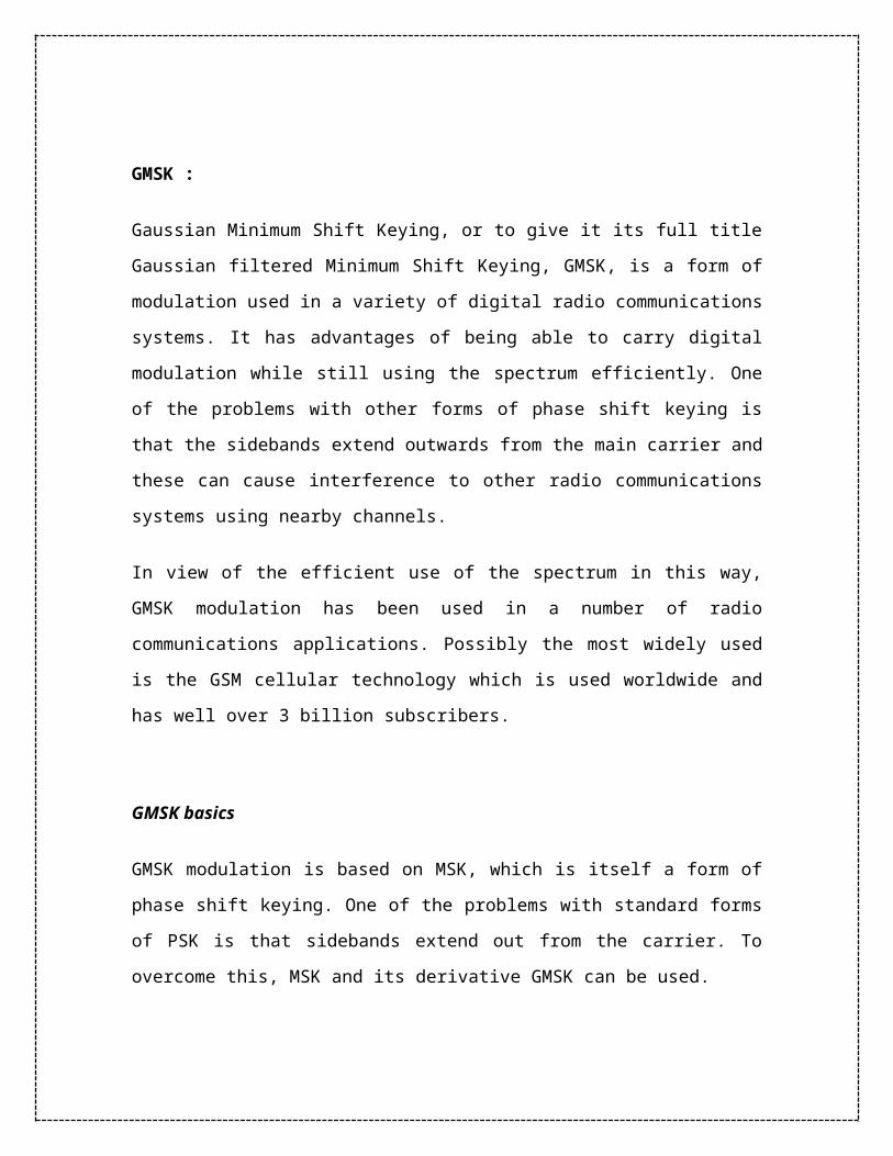
GMSK :
Gaussian Minimum Shift Keying, or to give it its full title Gaussian filtered Minimum
Shift Keying, GMSK, is a form of modulation used in a variety of digital radio
communications systems. It has advantages of being able to carry digital modulation
while still using the spectrum efficiently. One of the problems with other forms of phase
shift keying is that the sidebands extend outwards from the main carrier and these can
cause interference to other radio communications systems using nearby channels.
In view of the efficient use of the spectrum in this way, GMSK modulation has been used
in a number of radio communications applications. Possibly the most widely used is the
GSM cellular technology which is used worldwide and has well over 3 billion
subscribers.

GMSK basics
GMSK modulation is based on MSK, which is itself a form of phase shift keying. One of
the problems with standard forms of PSK is that sidebands extend out from the carrier.
To overcome this, MSK and its derivative GMSK can be used.
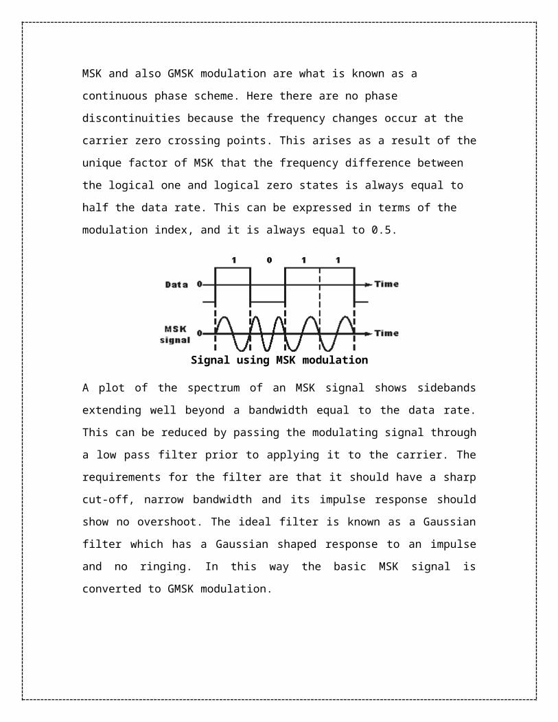
MSK and also GMSK modulation are what is known as a continuous phase scheme. Here
there are no phase discontinuities because the frequency changes occur at the carrier zero
crossing points. This arises as a result of the unique factor of MSK that the frequency
difference between the logical one and logical zero states is always equal to half the data
rate. This can be expressed in terms of the modulation index, and it is always equal to
0.5.
Signal using MSK modulation
A plot of the spectrum of an MSK signal shows sidebands extending well beyond a
bandwidth equal to the data rate. This can be reduced by passing the modulating signal
through a low pass filter prior to applying it to the carrier. The requirements for the filter
are that it should have a sharp cut-off, narrow bandwidth and its impulse response should
show no overshoot. The ideal filter is known as a Gaussian filter which has a Gaussian
shaped response to an impulse and no ringing. In this way the basic MSK signal is
converted to GMSK modulation.
Spectral density of MSK and GMSK signals
Generating GMSK modulation
There are two main ways in which GMSK modulation can be generated. The most obvious way is to filter the modulating signal using a Gaussian filter and then apply this to a frequency modulator where the modulation index is set to 0.5. This method is very simple and straightforward but it has the drawback that the modulation index must exactly equal 0.5. In practice this analogue method is not suitable because component tolerances drift and cannot be set exactly.
Generating GMSK using a Gaussian filter and VCO
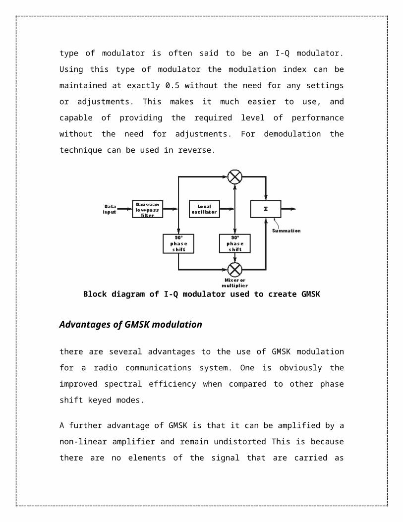
A second method is more widely used. Here what is known as a quadrature modulator is
used. The term quadrature means that the phase of a signal is in quadrature or 90 degrees
to another one. The quadrature modulator uses one signal that is said to be in-phase and
another that is in quadrature to this. In view of the in-phase and quadrature elements this
type of modulator is often said to be an I-Q modulator. Using this type of modulator the
modulation index can be maintained at exactly 0.5 without the need for any settings or
adjustments. This makes it much easier to use, and capable of providing the required
level of performance without the need for adjustments. For demodulation the technique
can be used in reverse.
Block diagram of I-Q modulator used to create GMSK
Advantages of GMSK modulation
there are several advantages to the use of GMSK modulation for a radio communications
system. One is obviously the improved spectral efficiency when compared to other phase
shift keyed modes.
A further advantage of GMSK is that it can be amplified by a non-linear amplifier and
remain undistorted This is because there are no elements of the signal that are carried as
amplitude variations. This advantage is of particular importance when using small
portable transmitters, such as those required by cellular technology. Non-linear amplifiers
are more efficient in terms of the DC power input from the power rails that they convert
into a radio frequency signal. This means that the power consumption for a given output
is much less, and this results in lower levels of battery consumption; a very important
factor for cell phones.
A further advantage of GMSK modulation again arises from the fact that none of the
information is carried as amplitude variations. This means that is immune to amplitude
variations and therefore more resilient to noise, than some other forms of modulation,
because most noise is mainly amplitude based.
Quadrature Amplitude Modulation

Quadrature Amplitude Modulation or QAM is a form of modulation which is widely used
for modulating data signals onto a carrier used for radio communications. It is widely
used because it offers advantages over other forms of data modulation such as PSK,
although many forms of data modulation operate along side each other.
Quadrature Amplitude Modulation, QAM is a signal in which two carriers shifted in
phase by 90 degrees are modulated and the resultant output consists of both amplitude
and phase variations. In view of the fact that both amplitude and phase variations are
present it may also be considered as a mixture of amplitude and phase modulation.
Analogue and digital QAM
Quadrature amplitude modulation, QAM may exist in what may be termed either
analogue or digital formats. The analogue versions of QAM are typically used to allow
multiple analogue signals to be carried on a single carrier. For example it is used in PAL
and NTSC television systems, where the different channels provided by QAM enable it to
carry the components of chroma or colour information. In radio applications a system
known as C-QUAM is used for AM stereo radio. Here the different channels enable the
two channels required for stereo to be carried on the single carrier.
Digital formats of QAM are often referred to as "Quantised QAM" and they are being
increasingly used for data communications often within radio communications systems.
Radio communications systems ranging from cellular technology through wireless
systems including WiMAX, and Wi-Fi 802.11 use a variety of forms of QAM, and the
use of QAM will only increase within the field of radio communications.
Digital / Quantised QAM basics
Quadrature amplitude modulation, QAM, when used for digital transmission for radio
communications applications is able to carry higher data rates than ordinary amplitude

modulated schemes and phase modulated schemes. As with phase shift keying, etc, the
number of points at which the signal can rest, i.e. the number of points on the
constellation is indicated in the modulation format description, e.g. 16QAM uses a 16
point constellation.
When using QAM, the constellation points are normally arranged in a square grid with
equal vertical and horizontal spacing and as a result the most common forms of QAM use
a constellation with the number of points equal to a power of 2 i.e. 2, 4, 8, 16 . . . .
By using higher order modulation formats, i.e. more points on the constellation, it is
possible to transmit more bits per symbol. However the points are closer together and
they are therefore more susceptible to noise and data errors.
To provide an example of how QAM operates, the table below provides the bit
sequences, and the associated amplitude and phase states. From this it can be seen that a
continuous bit stream may be grouped into threes and represented as a sequence of eight
permissible states.
Bit sequence Amplitude Phase (degrees)
000 1/2 0 (0°)
000 1 0 (0°)
010 1/2 π/2 (90°)
011 1 πi/2 (90°)
100 1/2 π (180°)
101 1 π (180°)
110 1/2 3πi/2 (270°)
111 1 3π/2 (270°)
Bit sequences, amplitudes and phases for 8-QAM
Phase modulation can be considered as a special form of QAM where the amplitude
remains constant and only the phase is changed. By doing this the number of possible
combinations is halved.
QAM advantages and disadvantages
Although QAM appears to increase the efficiency of transmission for radio
communications systems by utilising both amplitude and phase variations, it has a
number of drawbacks. The first is that it is more susceptible to noise because the states
are closer together so that a lower level of noise is needed to move the signal to a
different decision point. Receivers for use with phase or frequency modulation are both
able to use limiting amplifiers that are able to remove any amplitude noise and thereby
improve the noise reliance. This is not the case with QAM.
The second limitation is also associated with the amplitude component of the signal.
When a phase or frequency modulated signal is amplified in a radio transmitter, there is
no need to use linear amplifiers, whereas when using QAM that contains an amplitude
component, linearity must be maintained. Unfortunately linear amplifiers are less
efficient and consume more power, and this makes them less attractive for mobile
applications.
QAM comparison with other modes
As there are advantages and disadvantages of using QAM it is necessary to compare
QAM with other modes before making a decision about the optimum mode. Some radio
communications systems dynamically change the modulation scheme dependent upon the
link conditions and requirements - signal level, noise, data rate required, etc.
QAM applications
QAM is in many radio communications and data delivery applications. However some
specific variants of QAM are used in some specific applications and standards.
For domestic broadcast applications for example, 64 QAM and 256 QAM are often used
in digital cable television and cable modem applications. In the UK, 16 QAM and 64
QAM are currently used for digital terrestrial television using DVB - Digital Video
Broadcasting. In the US, 64 QAM and 256 QAM are the mandated modulation schemes
for digital cable as standardised by the SCTE in the standard ANSI/SCTE 07 2000.
In addition to this, variants of QAM are also used for many wireless and cellular
technology applications.
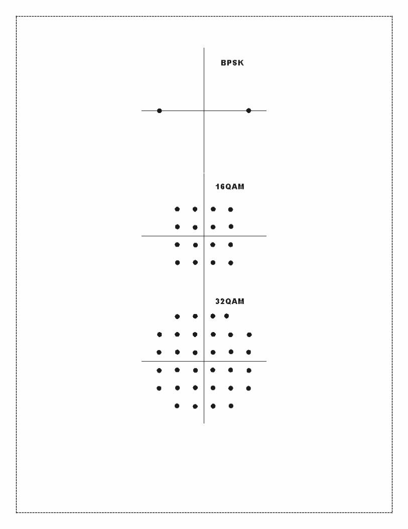
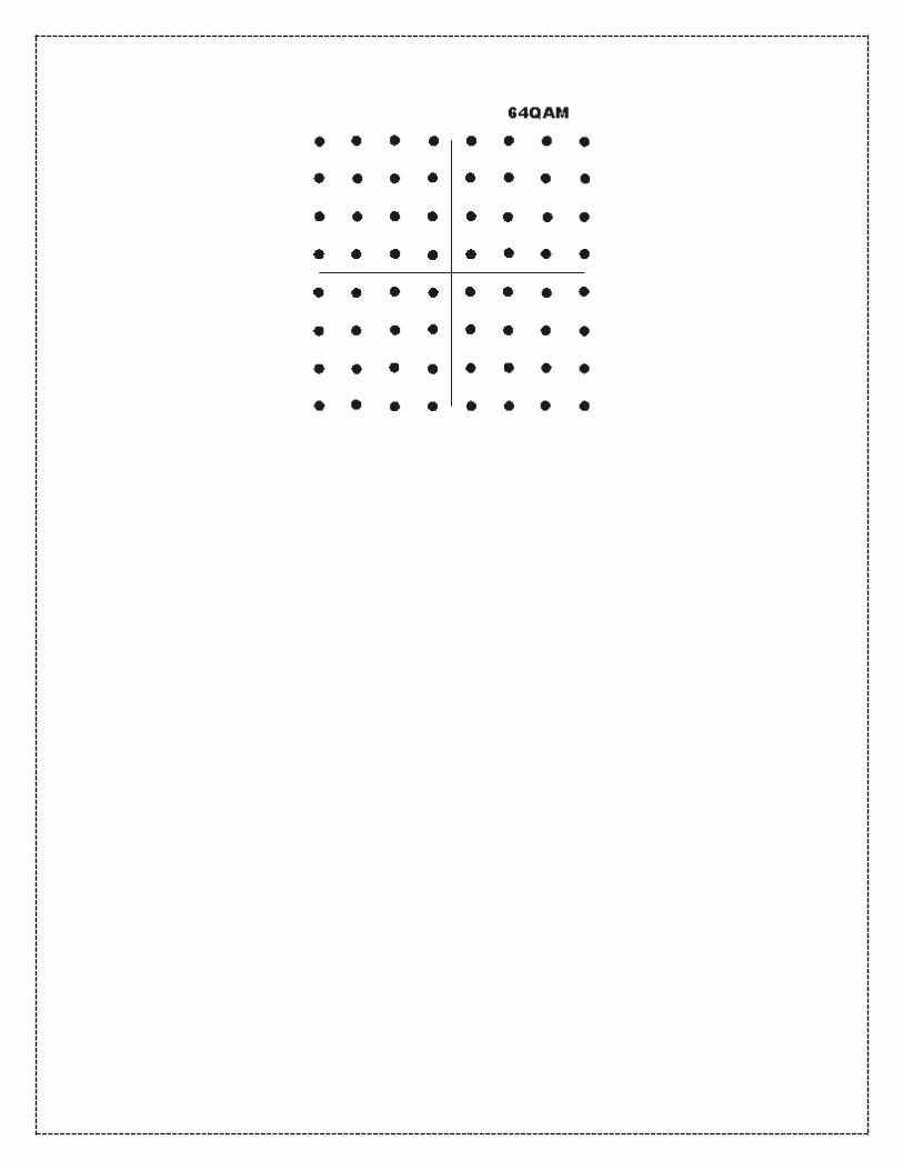
Constellation diagrams for QAM
The constellation diagrams show the different positions for the states within different
forms of QAM, quadrature amplitude modulation. As the order of the modulation
increases, so does the number of points on the QAM constellation diagram.
The diagrams below show constellation diagrams for a variety of formats of modulation:


UNIT III
SOURCE CODES, LINE CODES & ERROR CONTROL
ENTROPY:
In information theory, entropy is a measure of the uncertainty associated with a random
variable. Shannon's entropy represents an absolute limit on the best possible lossless
compression of any communication, under certain constraints: treating messages to be
encoded as a sequence of independent and identically-distributed random variables,
Shannon's source coding theorem shows that, in the limit, the average length of the
shortest possible representation to encode the messages in a given alphabet is their
entropy divided by the logarithm of the number of symbols in the target alphabet.

Entropy is really a notion of self information{the information provided by a random
process about itself. Mutual information is a measure of the information contained in one
process about another process. While entropy is sufficient to study the reproduction of a
single process through a noiseless environment, more often one has two or more distinct
random processes, e.g., one random process representing an information source and
another representing the output of a communication medium wherein the coded source
has been corrupted by another random process called noise. In such cases observations
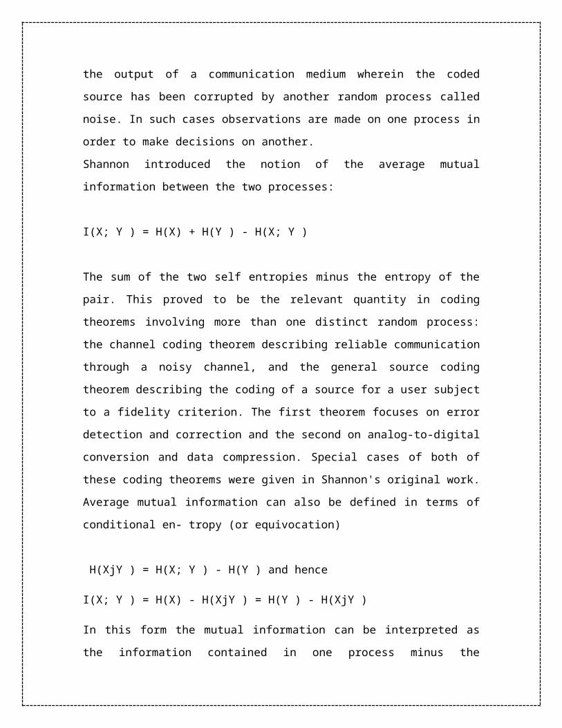
are made on one process in order to make decisions on another.
Shannon introduced the notion of the average mutual information between the two
processes:
I(X; Y ) = H(X) + H(Y ) - H(X; Y )
The sum of the two self entropies minus the entropy of the pair. This proved to be the
relevant quantity in coding theorems involving more than one distinct random process:
the channel coding theorem describing reliable communication through a noisy channel,
and the general source coding theorem describing the coding of a source for a user
subject to a fidelity criterion. The first theorem focuses on error detection and correction
and the second on analog-to-digital conversion and data compression. Special cases of
both of these coding theorems were given in Shannon's original work. Average mutual
information can also be defined in terms of conditional en- tropy (or equivocation)
H(XjY ) = H(X; Y ) - H(Y ) and hence
I(X; Y ) = H(X) - H(XjY ) = H(Y ) - H(XjY )
In this form the mutual information can be interpreted as the information contained in one
process minus the information contained in the process when the other process is known.
Let X be a discrete random variable with alphabet X = {1, 2, . . .m}. Assume there
is a probability mass function p(x) over X. How many binary questions, on average,
does it take to determine the outcome?
The entropy of a discrete random variable X is defined as:
which can interpreted as the expected value
SOURCE CODING
A (binary) source code C for a random variable X is a mapping fromvX to a
(finite) binary string. Let C(x) be the codeword corresponding to x and let l(x) denote the
length of C(x). We focus on codes that are “instantaneous”.
A code is called a prefix code or an instantaneous code if no codeword is a prefix
of any other codeword.
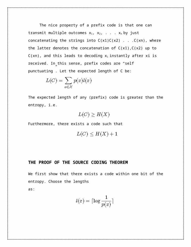
The nice property of a prefix code is that one can transmit multiple outcomes x1,
x2, . . . xn by just concatenating the strings into C(x1)C(x2) . . .C(xn), where the latter
denotes the concatenation of C(x1),C(x2) up to C(xn), and this leads to decoding xi
instantly after xi is received. In this sense, prefix codes are “self punctuating”. Let the
expected length of C be:
The expected length of any (prefix) code is greater than the entropy, i.e.
Furthermore, there exists a code such that
THE PROOF OF THE SOURCE CODING THEOREM
We first show that there exists a code within one bit of the entropy. Choose the lengths
as:
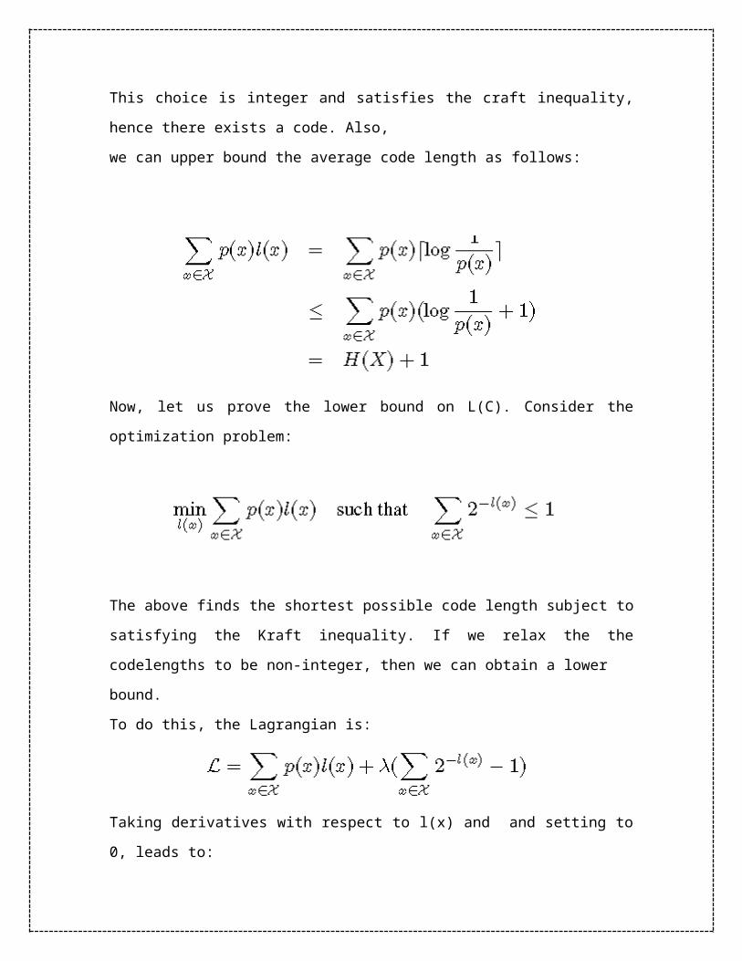
This choice is integer and satisfies the craft inequality, hence there exists a code. Also,
we can upper bound the average code length as follows:
Now, let us prove the lower bound on L(C). Consider the optimization problem:
The above finds the shortest possible code length subject to satisfying the Kraft
inequality. If we relax the the codelengths to be non-integer, then we can obtain a lower
bound.

To do this, the Lagrangian is:
Taking derivatives with respect to l(x) and and setting to 0, leads to:
Solving this for l(x) leads to
which can be verified by direct substitution. This proves the lower bound.
CONVOLUTION CODES
The probability of error can be reduced by transmitting more bits than needed to
represent the information being sent, and convolving each bit with neighbouring bits so
that if one transmitted bit got corrupted, enough information is carried by the
neighbouring bits to estimate what the corrupted bit was. This approach of transforming a
number of information bits into a larger number of transmitted bits is called channel
coding, and the particular approach of convolving the bits to distribute the information is
referred to as convolution coding. The ratio of information bits to transmitted bits is the
code rate (less than 1) and the number of information bits over which the convolution
takes place is the constraint length. For example, suppose you channel encoded a
message using a convolution code. Suppose you transmitted 2 bits for every information
bit (code rate=0.5) and used a constraint length of 3. Then the coder would send out 16
bits for every 8 bits of input, and each output pair would depend on the present and the
past 2 input bits (constraint length =3). The output would come out at twice the input
speed. Since information about each input bit is spread out over 6 transmitted bits, one
can usually reconstruct the correct input even with several transmission errors. The need
for coding is very important in the use of cellular phones. In this case, the “channel” is
the propagation of radio waves between your cell phone and the base station. Just by
turning your head while talking on the phone, you could suddenly block out a large
portion of the transmitted signal. If you tried to keep your head still, a passing bus could
change the pattern of bouncing radio waves arriving at your phone so that they add
destructively, again giving a poor signal. In both cases, the SNR suddenly drops deeply
and the bit error rate goes up dramatically. So the cellular environment is extremely
unreliable. If you didn’t have lots of redundancy in the transmitted bits to boost
reliability, chances are that digital cell phones would not be the success they are today.
Convolutional codes are commonly specified by three parameters; (n,k,m).
n = number of output bits
k = number of input bits
m = number of memory registers
The quantity k/n called the code rate, is a measure of the efficiency of the code.
Commonly k and n parameters range from 1 to 8, m from 2 to 10 and the code rate from
1/8 to 7/8 except for deep space applications where code rates as low as 1/100 or even
longer have been employed.
Often the manufacturers of convolutional code chips specify the code by parameters
(n,k,L), The quantity L is called the constraint length of the code and is defined by
Constraint Length, L = k (m-1)
The constraint length L represents the number of bits in the encoder memory that affect
the generation of the n output bits. The constraint length L is also referred to by the
capital letter K, which can be confusing with the lower case k, which represents the

number of input bits. In some books K is defined as equal to product the of k and m.
Often in commercial spec, the codes are specified by (r, K), where r = the code rate k/n
and K is the constraint length. The constraint length K however is equal to L – 1, as
defined in this paper. I will be referring to convolutional codes as (n,k,m) and not as
(r,K).
CODE PARAMETERS AND THE STRUCTURE OF THE CONVOLUTIONAL
CODE
The convolutional code structure is easy to draw from its parameters. First draw m boxes
representing the m memory registers. Then draw n modulo-2 adders to represent the n
output bits. Now connect the memory registers to the adders using the generator
polynomial as shown in the Fig. 1.
u1
v1
v2
u1 u0 u -1
v3
(1,1,1)
(1,0,1)
(0,1,1)
Figure 1 - This (3,1,3) convolutional code has 3 memory registers, 1 input bit and 3
output bits.
This is a rate 1/3 code. Each input bit is coded into 3 output bits. The constraint length of
the code is 2. The 3 output bits are produced by the 3 modulo-2 adders by adding up
certain bits in the memory registers. The selection of which bits are to be added to
produce the output bit is called the generator polynomial (g) for that output bit. For
example, the first output bit has a generator polynomial of (1,1,1). The output bit 2 has a

generator polynomial of (0,1,1) and the third output bit has a polynomial of (1,0,1). The
output bits just the sum of these bits.
v1 = mod2 (u1 + u0 + u-1)
v2 = mod2 ( u0 + u-1)
v3 = mod2 (u1 + u-1)
The polynomials give the code its unique error protection quality. One (3,1,4) code can
have completely different properties from an another one depending on the polynomials
chosen.
How polynomials are selected
There are many choices for polynomials for any m order code. They do not all result in
output sequences that have good error protection properties. Petersen and Weldon’s book
contains a complete list of these polynomials. Good polynomials are found from this list
usually by computer simulation. A list of good polynomials for rate ½ codes is given
below.
Table 1-Generator Polynomials found by Busgang for good rate ½ codes
Constraint
Length
G1 G2
3
4
5
6
7
8
110
1101
11010
110101
110101
110111
111
1110
11101
111011
110101
1110011

9
10
110111
110111001
111001101
1110011001
STATES OF A CODE
We have states of mind and so do encoders. We are depressed one day, and perhaps
happy the next from the many different states we can be in. Our output depends on our
states of mind and tongue-in-cheek we can say that encoders too act this way. What they
output depends on what is their state of mind. Our states are complex but encoder states
are just a sequence of bits. Sophisticated encoders have long constraint lengths and
simple ones have short in dicating the number of states they can be in.
The (2,1,4) code in Fig. 2 has a constraint length of 3. The shaded registers below hold
these bits. The unshaded register holds the incoming bit. This means that 3 bits or 8
different combination of these bits can be present in these memory registers. These 8
different combinations determine what output we will get for v1 and v2, the coded
sequence.
The number of combinations of bits in the shaded registers are called the states of the
code and are defined by
Number of states = 2L
where L = the constraint length of the code and is equal to k (m - 1).

Fig – The states of a code indicate what is in the memory registers
Think of states as sort of an initial condition. The output bit depends on this initial
condition which changes at each time tick.
Let’s examine the states of the code (2,1,4) shown above. This code outputs 2 bits for
every 1 input bit. It is a rate ½ code. Its constraint length is 3. The total number of states
is equal to 8.
The eight states of this (2,1,4) code are: 000, 001, 010, 011, 100, 101, 110, 111.
Punctured Codes
For the special case of k = 1, the codes of rates ½, 1/3, ¼, 1/5, 1/7 are sometimes called
mother codes. We can combine these single bit input codes to produce punctured codes
which give us code rates other than 1/n.
By using two rate ½ codes together as shown in the figure, and then just not transmitting
one of the output bits we can convert this rate ½ implementation into a 2/3 rate code. 2
bits come and 3 go out. This concept is called puncturing. On the receive side, dummy
u1
v1
v2
u1 u0 u-1 u-2
(1,1,1,1)
(1,1,0,1)
bits that do not affect the decoding metric are inserted in the appropriate places before
decoding.
Fig. - Two (2,1,3) convolutional codes produce 4 output bits. Bit number 3 is
“punctured” so the combination is effectively a (3,2,3) code.
This technique allows us to produce codes of many different rates using just one simple
hardware. Although we can also directly construct a code of rate 2/3 as we shall see later,
the advantage of a punctured code is that the rates can be changed dynamically (through
software) depending on the channel condition such as rain, etc. A fixed implementation,
although easier, does not allow this flexibility.
BLOCK CODES
In coding theory, block codes are one of the two common types of channel codes (the
other one being convolutional codes), which enable reliable transmission of digital data
over unreliable communication channels subject to channel noise.
A block code transforms a message m consisting of a sequence of information symbols
over an alphabet Σ into a fixed-length sequence c of n encoding symbols, called a code
word. In a linear block code, each input message has a fixed length of k < n input
symbols. The redundancy added to a message by transforming it into a larger code word
enables a receiver to detect and correct errors in a transmitted code word, and – using a
suitable decoding algorithm – to recover the original message. The redundancy is
described in terms of its information rate, or more simply – for a linear block code – in
terms of its code rate, k/n.
The error correction performance of a block code is described by the minimum
Hamming distance d between each pair of code words, and is called the distance of the
code.
Unit 4
MULTIPLE ACCESS TECHNIQUES
A limited amount of bandwidth is allocated for wireless services. A wireless system is
required to accommodate as many users as possible by effectively sharing the limited
bandwidth. Therefore, in the field of communications, the term multiple access could be
defined as a means of allowing multiple users to simultaneously share the finite
bandwidth with least possible degradation in the performance of the system. There are
several techniques how multiple accessing can be achieved. The are four basic schemes
1. Frequency Division Multiple Access (FDMA)
2. Time Division Multiple Access (TDMA)
3. Code Division Multiple Access (CDMA)
4. Space Division Multiple Access (SDMA)
Frequency Division Multiple Access (FDMA)
FDMA is one of the earliest multiple-access techniques for cellular systems when
continuous transmission is required for analog services. In this technique the bandwidth
is divided into a number of channels and distributed among users with a finite portion of
bandwidth for permanent use. The vertical axis that represents the code is shown here just
to make a clear comparison with CDMA (discussed later in this chapter). The channels
are assigned only when demanded by the users. Therefore when a channel is not in use it
becomes a wasted resource. FDMA channels have narrow bandwidth (30Khz). For this
reason, although x[n] is strictly the nth number in the sequence, we often refer to it as the
nth sample. We also often refer to \the sequence x[n]" when we mean the entire sequence.
Discrete-time signals are often depicted graphically as follows:
are usually implemented in narrowband systems. Since the user has his portion of
the bandwidth all the time, FDMA does not require synchronization or timing control,
which makes it algorithmically simple. Even though no two users use the same frequency
band at the same time, guard bands are introduced between frequency bands to minimize
adjacent channel interference. Guard bands are unused frequency slots that separate
neighboring channels. This leads to a waste of bandwidth. When continuous transmission
is not required, bandwidth goes wasted since it is not being utilized for a portion of the
time. In wireless communications, FDMA achieves simultaneous transmission and
reception by using Frequency division duplexing (FDD). In order for both the transmitter
and the receiver to operate at the same time, FDD requires duplexers.
Time Division Multiple Access (TDMA)
In digital systems, continuous transmission is not required because users do not
use the allotted bandwidth all the time. In such systems, TDMA is a complimentary
access technique to FDMA. Global Systems for Mobile communications (GSM) uses the
TDMA technique. In TDMA, the entire bandwidth is available to the user but only for a
finite period of time. In most cases the available bandwidth is divided into fewer channels
compared to FDMA and the users are allotted time slots during which they have the
entire channel bandwidth at their disposal. TDMA requires careful time synchronization
since users share the bandwidth in the frequency domain. Since the number of channels
are less, inter channel interference is almost negligible, hence the guard time between the
channels is considerably smaller. Guard time is a spacing in time between the TDMA
bursts. In cellular communications, when a user moves from one cell to another there is a
chance that user could experience a call loss if there are no free time slots available.
TDMA uses different time slots for transmission and reception. This type of duplexing is
referred to as Time division duplexing (TDD). TDD does not require duplexers.
Code Division Multiple Access
In CDMA, all the users occupy the same bandwidth, however they are all
assigned separate codes, which differentiates them from each other. CDMA systems
utilize a spread spectrum technique in which a spreading signal, which is uncorrelated to
the signal and has a large bandwidth, is used to spread the narrow band message signal.
Direct Sequence Spread Spectrum (DS-SS) is most commonly used for CDMA. In DS-
SS, the message signal is multiplied by a Pseudo Random Noise Code (PN code), which
has noise-like properties. Each user has his own codeword which is orthogonal to the
codes of other users. In order to detect the user, the receiver is required to know the
codeword used by the transmitter. Unlike TDMA, CDMA does not require time
synchronization between the users. A CDMA system experiences a problem called self-

jamming which arises when the spreading codes used for different users are not exactly
orthogonal. While dispreading, this leads to a significant contribution from other users to
the receiver decision statistic. If the power of the multiple users in a CDMA system is
unequal, then the user with the strongest signal power will be demodulated at the
receiver. The strength of the received signal raises the noise floor for the weaker signals
at the demodulators. This reduces the probability that weaker signals will be received.
This problem, known as the near-far problem can be taken care of by using power
control. This ensures that all the signals within the coverage of the base station arrive
with same power at the receiver.
Space Division Multiple Access (SDMA)
SDMA utilizes the spatial separation of the users in order to optimize the use of
the frequency spectrum. A primitive form of SDMA is when the same frequency is re-
used in different cells in a cellular wireless network. However for limited co-channel
interference it is required that the cells be sufficiently separated. This limits the number
of cells a region can be divided into and hence limits the frequency re-use factor. A more
advanced approach can further increase the capacity of the network. This technique
would enable frequency re-use within the cell. It uses a Smart Antenna technique that
employs antenna arrays backed by some intelligent signal processing to steer the antenna
pattern in the direction of the desired user and places nulls in the direction of the
interfering signals. Since these arrays can produce narrow spot beams, the frequency can
be re-used within the cell as long as the spatial separation between the users is sufficient.
In a practical cellular environment it is improbable to have just one transmitter fall within
the receiver beam width. Therefore it becomes imperative to use other multiple access
techniques in conjunction with SDMA. When different areas are covered by the antenna
beam, frequency can be re-used, in which case TDMA or CDMA is employed, for
different frequencies FDMA can be used.
UNIT 5
SATELLITE, OPTICAL FIBER – POWERLINE, SCADA
A satellite communication system will have a number of users operating via a
common satellite transponder, and this calls for sharing of the resources of power,
bandwidth and time. Here we describe these techniques and examine their implications,
with emphasis on principles rather than detailed structure or parameters of particular
networks, which tend to be very system specific. The term used for such sharing and
management of a number of different channels is multiple access.
Types of Satellite Orbits
There are three basic kinds of orbits, depending on the satellite's position relative to
Earth's surface:

Geostationary orbits (also called geosynchronous or synchronous) are orbits in
which the satellite is always positioned over the same spot on Earth. Many
geostationary satellites are above a band along the equator, with an altitude of
about 22,223 miles, or about a tenth of the distance to the Moon. The "satellite
parking strip" area over the equator is becoming congested with several hundred
television, weather and communication satellites! This congestion means each
satellite must be precisely positioned to prevent its signals from interfering with
an adjacent satellite's signals. Television, communications and weather satellites
all use geostationary orbits. Geostationary orbits are why a DSS satellite TV dish
is typically bolted in a fixed position.
The scheduled Space Shuttles use a much lower, asynchronous orbit, which
means they pass overhead at different times of the day. Other satellites in
asynchronous orbits average about 400 miles (644 km) in altitude.
In a polar orbit, the satellite generally flies at a low altitude and passes over the
planet's poles on each revolution. The polar orbit remains fixed in space as Earth
rotates inside the orbit. As a result, much of Earth passes under a satellite in a
polar orbit. Because polar orbits achieve excellent coverage of the planet, they are
often used for satellites that do mapping and photography.
Cellular CDMA
Mobile telephony, using the concept of cellular architecture, has been very popular
world wide. Such systems are built based on accepted standards, such as GSM (Global
System for Mobile communication) and IS-95(Intermediate Standard-95). Several
standards of present and future generations of mobile communication systems include
CDMA as an important component which allows a satisfactorily large number of users to
communicate simultaneously over a common radio frequency band.
Cellular CDMA is a promising access technique for supporting multimedia services
in a mobile environment as it helps to reduce the multi-path fading effects and
interference. It also supports universal frequency reuse, which implies large teletraffic
capacity to accommodate new calling subscribers. In a practical system, however, the
actual number of users who can simultaneously use the RF band satisfactorily is limited
by the amount of interference generated in the air interface. A good feature is that the
teletraffic capacity is ‘soft’, i.e. there is no ‘hard’ or fixed value for the maximum
capacity. The quality of received signal degrades gracefully with increase in the number
of active users at a given point of time.
It is interesting to note that the quality of a radio link in a cellular system is often
indicated by the Signal-to-Interference Ratio (SIR), rather than the common metric
‘SNR’. Let us remember that in a practical system, the spreading codes used by all the
simultaneous users in a cell have some cross-correlation amongst themselves and also
due to other propagation features, the signals received in a handset from all transmitters
do not appear orthogonal to each other. Hence, the signals from all users, other than the
desired transmitter, manifest as interference. In a practical scenario, the total interference
power may even momentarily exceed the power of the desired signal. This happens
especially when the received signals fluctuate randomly (fading) due to mobility of the
users. Fading is a major factor degrading the performance of a CDMA system. While
large-scale fading consists of path loss and shadowing, small-scale fading refers to rapid
changes in signal amplitude and phase over a small spatial separation.
The desired signal at a receiver is said to be ‘in outage’ (i.e. momentarily lost)
when the SIR goes below an acceptable threshold level. An ongoing conversation may
get affected adversely if the outage probability is high or if the duration of outage (often
called as ‘fade duration’) is considerable. On the other hand, low outage probability and
insignificant ‘average fade duration’ in a CDMA system usually implies that more users
could be allowed in the system ensuring good quality of signal.
OPTICAL FIBRE:
An optical fiber is a flexible, transparent fiber made of very pure glass (silica)
not much bigger than a human hair that acts as a waveguide, or "light pipe", to transmit
light between the two ends of the fiber. The field of applied science and engineering
concerned with the design and application of optical fibers is known as fiber optics.
Optical fibers are widely used in fiber-optic communications, which permits transmission
over longer distances and at higher bandwidths (data rates) than other forms of
communication. Fibers are used instead of metal wires because signals travel along them
with less loss and are also immune to electromagnetic interference. Fibers are also used
for illumination, and are wrapped in bundles so they can be used to carry images, thus
allowing viewing in tight spaces. Specially designed fibers are used for a variety of other
applications, including sensors and fiber lasers.
An optical fiber junction box. The yellow cables are single mode fibers; the
orange and blue cables are multi-mode fibers: 50/125 µm OM2 and 50/125 µm OM3
fibers respectively. Optical fiber typically consists of a transparent core surrounded by a
transparent cladding material with a lower index of refraction. Light is kept in the core by
total internal reflection. This causes the fiber to act as a waveguide. Fibers that support
many propagation paths or transverse modes are called multi-mode fibers (MMF), while
those that only support a single mode are called single-mode fibers (SMF). Multi-mode
fibers generally have a larger core diameter, and are used for short-distance
communication links and for applications where high power must be transmitted. Single-
mode fibers are used for most communication links longer than 1,050 meters (3,440 ft).
OPTICAL DETECTORS
The detection of optical radiation is usually accomplished by converting the
optical energy into an electrical signal. Optical detectors include photon detectors, in
which one photon of light energy releases one electron that is detected in the electronic
circuitry, and thermal detectors, in which the optical energy is converted into heat, which
then generates an electrical signal. Often the detection of optical energy must be
performed in the presence of noise sources, which interfere with the detection process.
The detector circuitry usually employs a bias voltage and a load resistor in series with the
detector. The incident light changes the characteristics of the detector and causes the
current flowing in the circuit to change. The output signal is the change in voltage drop
across the load resistor. Many detector circuits are designed for specific applications.
Avalanche photodetectors (APDs) are used in long-haul fiber
optic systems, since they have superior sensitivity, as much as 10 dB
better than PIN diodes. Basically, an APD is a P-N junction photodiode
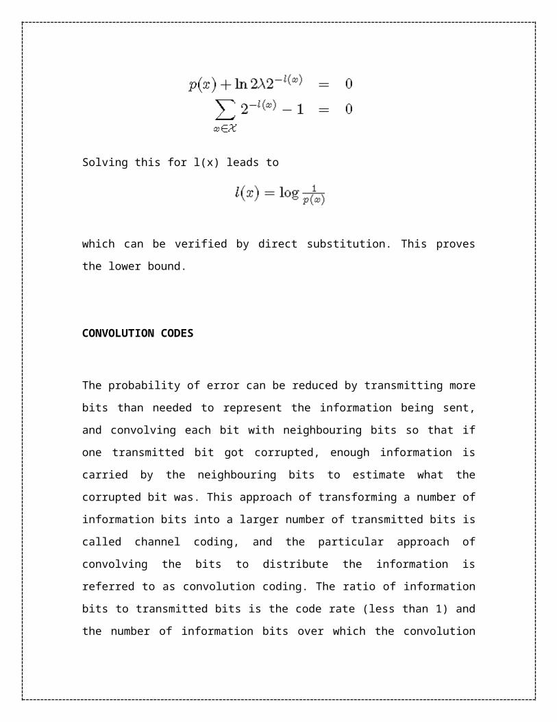
operated with high reverse bias. The materials is typically InP/InGaAs.
With the high applied potential, impact ionization from the lightwave
generates electron-hole pairs that subsequently cause an avalanche
across the potential barrier. This current gain gives the APD its greater
sensitivity. APDs are commonly used up to 2.5 Gbps and sometimes to
10 Gbps if the extra cost can be justified.
Silicon photodiodes (APDs) are used in lower frequency systems
(up to 1.5 or 2 GHz) where they can meet low cost and modest
frequency response requirements. Si devices are used in pairs in
wavelength sensors. The ratio of longer and shorter wavelength
sensors is proportional to the input wavelength. Hopefully, this short
tutorial provides a useful introduction to an important part of optical
communication systems.
Related Documents