AIP Belgium and Luxembourg AD 2.EBBR-1 © AIM BELGIUM EBBR - BRUSSELS / Brussels-National EBBR AD 2.1 Aerodrome Location Indicator and Name EBBR - BRUSSELS / Brussels-National EBBR AD 2.2 Aerodrome Geographical and Administrative Data EBBR AD 2.3 Operational Hours 1 ARP coordinates 505405N 0042904E Site of ARP at aerodrome 246º MAG / 1.8 KM from TWR 2 Direction and distance from (city) 6.5NM NE of Brussels 3 Elevation / reference temperature 184FT / 23°C 4 Geoid undulation 141FT 5 Magnetic variation / annual change 1°E (2015) / INFO not AVBL 6 AD administration address Brussels Airport Company Brussels Airport 1930 Zaventem BELGIUM TEL +32 (0) 2 753 42 00 (office hours only) +32 (0) 2 753 69 00 (Airport Inspection, H24) FAX +32 (0) 2 753 69 09 (Airport Inspection) Telex NIL AFS EBBRYDYX Email NIL 7 Types of traffic permitted (IFR / VFR) IFR / VFR 8 Remarks NIL 1 AD Administration H24 2 Customs and immigration H24 3 Health and sanitation H24 4 AIS Briefing Office H24 5 ATS Reporting Office (ARO) H24 6 MET Briefing Office H24 7 ATS H24 8 Fuelling H24 (Between 2100 and 0500 (2000 and 0400), only with credit cards acceptable by the chosen petroleum company) 9 Handling H24 10 Security H24 11 De-icing H24 12 Remarks See also EBBR AD 2.20, § 1 and EBBR AD 2.21, § 1 . AMDT 004/2018 29-MAR-2018 29-MAR-2018

Welcome message from author
This document is posted to help you gain knowledge. Please leave a comment to let me know what you think about it! Share it to your friends and learn new things together.
Transcript

AIP Belgium and Luxembourg AD 2.EBBR-1
© AIM BELGIUM
EBBR - BRUSSELS / Brussels-National
EBBR AD 2.1 Aerodrome Location Indicator and Name
EBBR - BRUSSELS / Brussels-National
EBBR AD 2.2 Aerodrome Geographical and Administrative Data
EBBR AD 2.3 Operational Hours
1ARP coordinates 505405N 0042904E
Site of ARP at aerodrome 246º MAG / 1.8KM from TWR
2 Direction and distance from (city) 6.5NM NE of Brussels
3 Elevation / reference temperature 184FT / 23°C
4 Geoid undulation 141FT
5 Magnetic variation / annual change 1°E (2015) / INFO not AVBL
6
AD administration address
Brussels Airport CompanyBrussels Airport1930 ZaventemBELGIUM
TEL +32 (0) 2 753 42 00 (office hours only)+32 (0) 2 753 69 00 (Airport Inspection, H24)
FAX +32 (0) 2 753 69 09 (Airport Inspection)
Telex NIL
AFS EBBRYDYX
Email NIL
7 Types of traffic permitted (IFR / VFR) IFR / VFR
8 Remarks NIL
1 AD Administration H24
2 Customs and immigration H24
3 Health and sanitation H24
4 AIS Briefing Office H24
5 ATS Reporting Office (ARO) H24
6 MET Briefing Office H24
7 ATS H24
8 Fuelling H24 (Between 2100 and 0500 (2000 and 0400), only with credit cards acceptable by the chosen petroleum company)
9 Handling H24
10 Security H24
11 De-icing H24
12 Remarks See also EBBR AD 2.20, § 1 and EBBR AD 2.21, § 1.
AMDT 004/2018
29-MAR-2018
29-MAR-2018
AD 2.EBBR-2 AIP Belgium and Luxembourg
© AIM BELGIUM
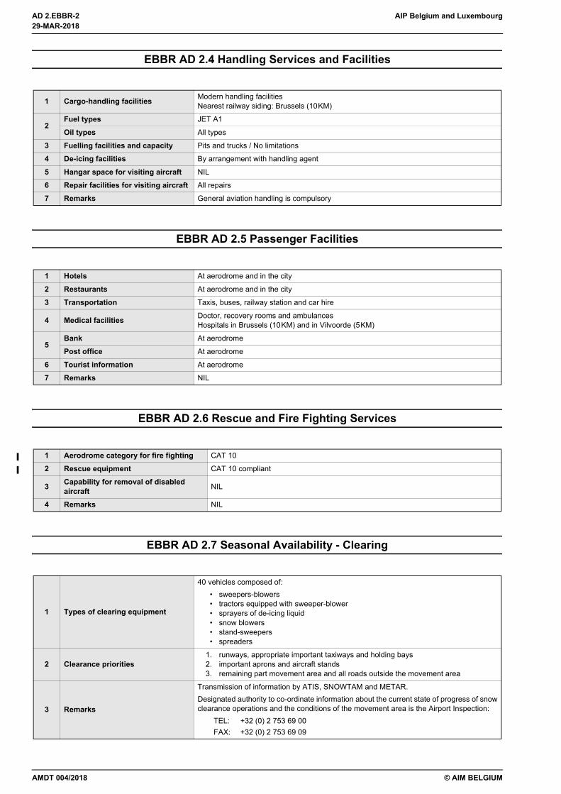
EBBR AD 2.4 Handling Services and Facilities
EBBR AD 2.5 Passenger Facilities
EBBR AD 2.6 Rescue and Fire Fighting Services
EBBR AD 2.7 Seasonal Availability - Clearing
1 Cargo-handling facilities Modern handling facilitiesNearest railway siding: Brussels (10KM)
2Fuel types JET A1
Oil types All types
3 Fuelling facilities and capacity Pits and trucks / No limitations
4 De-icing facilities By arrangement with handling agent
5 Hangar space for visiting aircraft NIL
6 Repair facilities for visiting aircraft All repairs
7 Remarks General aviation handling is compulsory
1 Hotels At aerodrome and in the city
2 Restaurants At aerodrome and in the city
3 Transportation Taxis, buses, railway station and car hire
4 Medical facilities Doctor, recovery rooms and ambulancesHospitals in Brussels (10KM) and in Vilvoorde (5KM)
5Bank At aerodrome
Post office At aerodrome
6 Tourist information At aerodrome
7 Remarks NIL
1 Aerodrome category for fire fighting CAT 10
2 Rescue equipment CAT 10 compliant
3 Capability for removal of disabled aircraft NIL
4 Remarks NIL
1 Types of clearing equipment
40 vehicles composed of:• sweepers-blowers• tractors equipped with sweeper-blower• sprayers of de-icing liquid• snow blowers• stand-sweepers• spreaders
2 Clearance priorities1. runways, appropriate important taxiways and holding bays2. important aprons and aircraft stands3. remaining part movement area and all roads outside the movement area
3 Remarks
Transmission of information by ATIS, SNOWTAM and METAR.Designated authority to co-ordinate information about the current state of progress of snowclearance operations and the conditions of the movement area is the Airport Inspection:
TEL: +32 (0) 2 753 69 00FAX: +32 (0) 2 753 69 09
29-MAR-2018
29-MAR-2018
AMDT 004/2018
AIP Belgium and Luxembourg AD 2.EBBR-3
© AIM BELGIUM
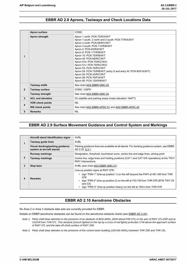
EBBR AD 2.8 Aprons, Taxiways and Check Locations Data
EBBR AD 2.9 Surface Movement Guidance and Control System and Markings
EBBR AD 2.10 Aerodrome Obstacles
No Area 2 or Area 3 obstacle data sets are currently provided for EBBR.
Details on EBBR aerodrome obstacles can be found on the aerodrome obstacle charts (see EBBR AD 2.24).
Note 1: Pilots shall draw attention to the presence of an obstacle of 86M AMSL (46M aboveTHR 07L) in the axis of RWY 07L/25R and at 1610M from THR 07L. This obstacle (church lighted on the top by a cross of red lights) protrudes 17M above the approach surface of RWY 07L and the take-off climb surface of RWY 25R.
Note 2: Pilots shall draw attention to the presence of the control tower building (109.6M AMSL) between THR 25R and THR 25L.
1
Apron surface CONC
Apron strength Apron 1 north: PCN 72/R/A/W/TApron 1 south, 2 north and 2 south: PCN 77/R/A/W/TApron 3 north: PCN 68/R/C/W/TApron 3 south: PCN 110/R/B/W/TApron 4: PCN 63/R/D/W/TApron 9: PCN 117/R/B/W/TApron 10: PCN 75/R/B/W/TApron 40: PCN 68/R/C/W/TApron 51b: PCN 70/R/C/W/UApron 51c: PCN 70/R/C/W/UApron 53: PCN 76/R/C/W/TApron 54: PCN 73/R/B/W/T (entry S and entry W: PCN 80/F/A/W/T)Apron 55: PCN 43/R/C/W/TApron 56: PCN 76/F/A/W/TApron 60: PCN 120/R/B/W/T
2Taxiway width See chart AD2 EBBR-GMC.02
Taxiway surface CONC / ASPH
Taxiway strength See chart AD2 EBBR-GMC.02
3 ACL and elevation On satellite and parking areas (mean elevation 184FT)
4VOR check points NIL
INS check points See chart AD2 EBBR-APDC.01 and AD2 EBBR-APDC.02
5 Remarks NIL
1
Aircraft stand identification signs AVBL
Taxiway guide lines AVBL
Visual docking/parking guidance system at aircraft stands
Parking guidance lines are available at all stands. For docking guidance system, see EBBR AD 2.20, § 3.1.
2Runway markings Designation, threshold, touchdown zone, centre line and edge lines, aiming point
Taxiway markings Centre line, edge lines and holding positions (CAT I and CAT II/III operations) at the TWY/RWY intersections
3 Stop bars AVBL (see chart AD2 EBBR GMC.01)
4 Remarks
Line-up position signs at RWY 07R:• sign “PSN 1" (line-up position 1) on the left beyond the PAPI at 461.4M from THR
07R• sign “PSN 2" (line-up position 2) on the left at 743.7M from THR 07R (BTN TWY C6
and C5)• sign “PSN H” (line-up position heavy) on the left at 194m from THR 07R
AIRAC AMDT 007/2017
20-JUL-2017
20-JUL-2017
AD 2.EBBR-4 AIP Belgium and Luxembourg
© AIM BELGIUM
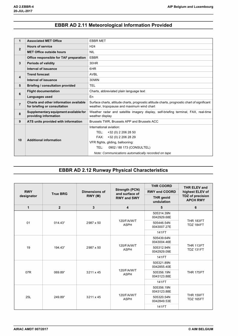
EBBR AD 2.11 Meteorological Information Provided
EBBR AD 2.12 Runway Physical Characteristics
1 Associated MET Office EBBR MET
2Hours of service H24
MET Office outside hours NIL
3Office responsible for TAF preparation EBBR
Periods of validity 30HR
Interval of issuance 6HR
4Trend forecast AVBL
Interval of issuance 30MIN
5 Briefing / consultation provided TEL
6Flight documentation Charts, abbreviated plain language text
Languages used En
7 Charts and other information available for briefing or consultation
Surface charts, altitude charts, prognostic altitude charts, prognostic chart of significant weather, tropopause and maximum wind chart
8 Supplementary equipment available for providing information
Weather radar and satellite imagery display, self-briefing terminal, FAX, real-timeweather display
9 ATS units provided with information Brussels TWR, Brussels APP and Brussels ACC
10 Additional information
International aviation:TEL: +32 (0) 2 206 28 50FAX: +32 (0) 2 206 28 29
VFR flights, gliding, ballooning:TEL: 0902 / 88 173 (CONSULTEL)
Note: Communications automatically recorded on tape
RWY designator True BRG Dimensions of
RWY (M)
Strength (PCN) and surface of RWY and SWY
THR COORD THR ELEV and highest ELEV of TDZ of precision
APCH RWY
RWY end COORDTHR geoid undulation
1 2 3 4 5 6
01 014.43° 2987 x 50 120/F/A/W/TASPH
505314.39N0042929.68E
THR 183FTTDZ 184FT505446.54N
0043007.27E
141FT
19 194.43° 2987 x 50 120/F/A/W/TASPH
505439.64N0043004.46E
THR 113FTTDZ 131FT505312.94N
0042929.09E
141FT
07R 069.89° 3211 x 45 120/F/A/W/TASPH
505321.89N0042855.40E
THR 175FT505356.19N0043123.88E
141FT
25L 249.89° 3211 x 45 120/F/A/W/TASPH
505356.19N0043123.88E
THR 159FTTDZ 165FT505320.54N
0042849.53E
141FT
20-JUL-2017
20-JUL-2017
AIRAC AMDT 007/2017
AIP Belgium and Luxembourg AD 2.EBBR-5
© AIM BELGIUM
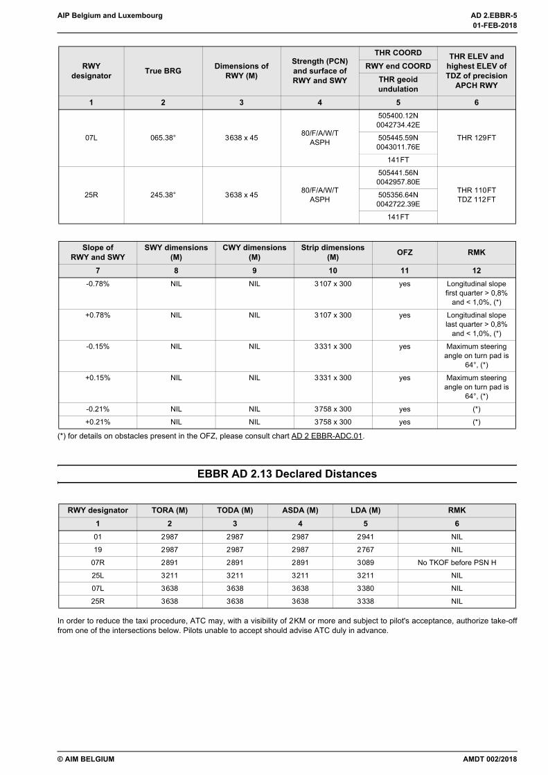
(*) for details on obstacles present in the OFZ, please consult chart AD 2 EBBR-ADC.01.
EBBR AD 2.13 Declared Distances
In order to reduce the taxi procedure, ATC may, with a visibility of 2KM or more and subject to pilot's acceptance, authorize take-offfrom one of the intersections below. Pilots unable to accept should advise ATC duly in advance.
07L 065.38° 3638 x 45 80/F/A/W/TASPH
505400.12N0042734.42E
THR 129FT505445.59N0043011.76E
141FT
25R 245.38° 3638 x 45 80/F/A/W/TASPH
505441.56N0042957.80E
THR 110FTTDZ 112FT505356.64N
0042722.39E
141FT
Slope ofRWY and SWY
SWY dimensions (M)
CWY dimensions (M)
Strip dimensions (M) OFZ RMK
7 8 9 10 11 12-0.78% NIL NIL 3107 x 300 yes Longitudinal slope
first quarter > 0,8% and < 1,0%, (*)
+0.78% NIL NIL 3107 x 300 yes Longitudinal slope last quarter > 0,8%
and < 1,0%, (*)
-0.15% NIL NIL 3331 x 300 yes Maximum steering angle on turn pad is
64°, (*)
+0.15% NIL NIL 3331 x 300 yes Maximum steering angle on turn pad is
64°, (*)
-0.21% NIL NIL 3758 x 300 yes (*)
+0.21% NIL NIL 3758 x 300 yes (*)
RWY designator TORA (M) TODA (M) ASDA (M) LDA (M) RMK1 2 3 4 5 601 2987 2987 2987 2941 NIL
19 2987 2987 2987 2767 NIL
07R 2891 2891 2891 3089 No TKOF before PSN H
25L 3211 3211 3211 3211 NIL
07L 3638 3638 3638 3380 NIL
25R 3638 3638 3638 3338 NIL
RWY designator True BRG Dimensions of
RWY (M)
Strength (PCN) and surface of RWY and SWY
THR COORD THR ELEV and highest ELEV of TDZ of precision
APCH RWY
RWY end COORDTHR geoid undulation
1 2 3 4 5 6
AMDT 002/2018
01-FEB-2018
01-FEB-2018
AD 2.EBBR-6 AIP Belgium and Luxembourg
© AIM BELGIUM
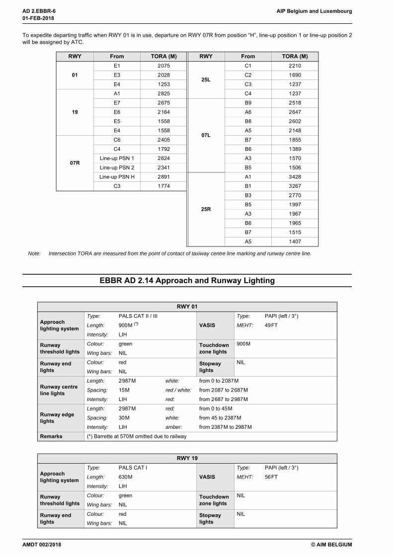
To expedite departing traffic when RWY 01 is in use, departure on RWY 07R from position “H”, line-up position 1 or line-up position 2will be assigned by ATC.
Note: Intersection TORA are measured from the point of contact of taxiway centre line marking and runway centre line.
EBBR AD 2.14 Approach and Runway Lighting
RWY From TORA (M) RWY From TORA (M)
01E1 2075
25L
C1 2210
E3 2028 C2 1690
E4 1253 C3 1237
19
A1 2825 C4 1237
E7 2675
07L
B9 2518
E6 2164 A6 2647
E5 1558 B8 2602
E4 1558 A5 2148
07R
C6 2405 B7 1855
C4 1792 B6 1389
Line-up PSN 1 2624 A3 1570
Line-up PSN 2 2341 B5 1506
Line-up PSN H 2891
25R
A1 3428
C3 1774 B1 3267
B3 2770
B5 1997
A3 1967
B6 1965
B7 1515
A5 1407
RWY 01
Approach lighting system
Type: PALS CAT II / III
VASISType: PAPI (left / 3°)
Length: 900M (*) MEHT: 49FT
Intensity: LIH
Runway threshold lights
Colour: green Touchdown zone lights
900M
Wing bars: NIL
Runway end lights
Colour: red Stopway lights
NIL
Wing bars: NIL
Runway centre line lights
Length: 2987M white: from 0 to 2087M
Spacing: 15M red / white: from 2087 to 2687M
Intensity: LIH red: from 2687 to 2987M
Runway edge lights
Length: 2987M red: from 0 to 45M
Spacing: 30M white: from 45 to 2387M
Intensity: LIH amber: from 2387M to 2987M
Remarks (*) Barrette at 570M omitted due to railway
RWY 19
Approach lighting system
Type: PALS CAT I
VASISType: PAPI (left / 3°)
Length: 630M MEHT: 56FT
Intensity: LIH
Runway threshold lights
Colour: green Touchdown zone lights
NIL
Wing bars: NIL
Runway end lights
Colour: red Stopway lights
NIL
Wing bars: NIL
01-FEB-2018
01-FEB-2018
AMDT 002/2018
AIP Belgium and Luxembourg AD 2.EBBR-7
© AIM BELGIUM
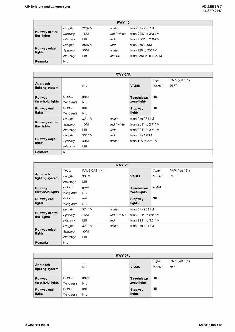
Runway centre line lights
Length: 2987M white: from 0 to 2087M
Spacing: 15M red / white: from 2087 to 2687M
Intensity: LIH red: from 2687 to 2987M
Runway edge lights
Length: 2987M red: from 0 to 220M
Spacing: 30M white: from 220 to 2387M
Intensity: LIH amber: from 2387M to 2987M
Remarks NIL
RWY 07R
Approach lighting system VASIS
Type: PAPI (left / 3°)
NIL MEHT: 66FT
Runway threshold lights
Colour: green Touchdown zone lights
NIL
Wing bars: NIL
Runway end lights
Colour: red Stopway lights
NIL
Wing bars: NIL
Runway centre line lights
Length: 3211M white: from 0 to 2311M
Spacing: 15M red / white: from 2311 to 2911M
Intensity: LIH red: from 2911 to 3211M
Runway edge lights
Length: 3211M red: from 0 to 125M
Spacing: 30M white: from 125 to 3211M
Intensity: LIH
Remarks NIL
RWY 25L
Approach lighting system
Type: PALS CAT II / III
VASISType: PAPI (left / 3°)
Length: 900M MEHT: 63FT
Intensity: LIH
Runway threshold lights
Colour: green Touchdown zone lights
900M
Wing bars: NIL
Runway end lights
Colour: red Stopway lights
NIL
Wing bars: NIL
Runway centre line lights
Length: 3211M white: from 0 to 2311M
Spacing: 15M red / white: from 2311 to 2911M
Intensity: LIH red: from 2911 to 3211M
Runway edge lights
Length: 3211M white: from 0 to 3211M
Spacing: 30M
Intensity: LIH
Remarks NIL
RWY 07L
Approach lighting system VASIS
Type: PAPI (left / 3°)
NIL MEHT: 66FT
Runway threshold lights
Colour: green Touchdown zone lights
NIL
Wing bars: NIL
Runway end lights
Colour: red Stopway lights
NIL
Wing bars: NIL
RWY 19
AMDT 010/2017
14-SEP-2017
14-SEP-2017

AD 2.EBBR-8 AIP Belgium and Luxembourg
© AIM BELGIUM
EBBR AD 2.15 Other Lighting, Secondary Power Supply
EBBR AD 2.16 Helicopter Landing Area
Runway centre line lights
Length: 3638M white: from 0 to 2738M
Spacing: 15M red / white: from 2738 to 3338M
Intensity: LIH red: from 3338 to 3638M
Runway edge lights
Length: 3638M red: from 0 to 258M
Spacing: 30M white: from 258 to 3638M
Intensity: LIH
Remarks NIL
RWY 25R
Approach lighting system
Type: PALS CAT II / III
VASISType: PAPI (right / 3°)
Length: 600M MEHT: 61FT
Intensity: LIH
Runway threshold lights
Colour: green Touchdown zone lights
900M
Wing bars: NIL
Runway end lights
Colour: red Stopway lights
NIL
Wing bars: NIL
Runway centre line lights
Length: 3608M white: from 30 to 2738M
Spacing: 15M red / white: from 2738 to 3338M
Intensity: LIH red: from 3338 to 3638M
Runway edge lights
Length: 3638M red: from 0 to 300M
Spacing: 30M white: from 300 to 3638M
Intensity: LIH
Remarks NIL
1 ABN / IBN location, characteristics and hours of operation NIL
2
LDI location and lighting NIL
WDI location and lighting
At THR 07L (lighted)At 198M from THR 07R (lighted)At 378M from THR 25L (lighted)At 430M from THR 19 and 209M from THR 25R (lighted)At 472M from THR 01 and 940M from THR 07R (lighted)
3Taxiway edge lighting See chart AD2 EBBR GMC.02
Taxiway centre line lighting See chart AD2 EBBR GMC.02
4Secondary power supply AVBL
Switch-over time 0 SEC
5 Remarks NIL
1 Coordinates of TLOF and FATO THR
505348.28N 0042758.57EThe FATO is located on TWY R1
2 TLOF / FATO elevation 124FT
3TLOF dimensions 22M x 22M
TLOF surface ASPH
TLOF strength PCN 75/F/C/W/T
RWY 07L
14-SEP-2017
14-SEP-2017
AMDT 010/2017

AIP Belgium and Luxembourg AD 2.EBBR-9
© AIM BELGIUM
EBBR AD 2.17 ATS Airspace
4 FATO true bearing 065° / 245°
5 Declared distances available Information not available. See remarks on the restrictions of use.
6 TLOF and FATO marking Marked with a conventional H (dimensions 6M x 3.6M). There is no aiming point provided, a WDI is located on the west side.
7 Approach and FATO lighting Information not available. See remarks.
8 Remarks
State and military flights are exempted.Performance class 1 operations are not allowed to/from the FATO due to the slope ofobstacle limitation surfaces that comply to performance class 2 & 3 only.The take-off and climb surface has been protected to 8% to the east and west of the FATO.Caution must be exercised when operating to and from the FATO due to possible movingaircraft and vehicles.The FATO shall be vacated immediately after landing according ATC instructions.Helicopters with skid-type landing gear proceeding to and from the FATO shall hover taxito and from the parking area.Helicopters with wheel-type landing gear proceeding to and from the FATO shall groundtaxi to and from the parking area.
1Designation Brussels CTR
Lateral limits 504434N 0043404E - an arc of circle, 10NM radius, centred on 505405N 0042904E and traced clockwise to 505203N 0044435E - 504434N 0043404E.
2 Vertical limits 1500FT AMSL
3 Airspace classification D (1)
4ATS unit call sign Brussels Tower
Language(s) En
5 Transition altitude 4500FT AMSL
6 Remarks
(1) Partially airspace class G during EBGB operational hours between GND and 1000FT AMSL: 510401N 0042700E - 505800N 0042800E - 505545N 0042452E - 505800N 0041428E - an arc of circle, 10NM radius, centred on 505405N 0042904E and traced clockwise to 510401N 0042700E (see chart AD2 EBBR-VAC.01 and AD 2.PVT-EBGB).
AMDT 004/2018
29-MAR-2018
29-MAR-2018
AD 2.EBBR-10 AIP Belgium and Luxembourg
© AIM BELGIUM
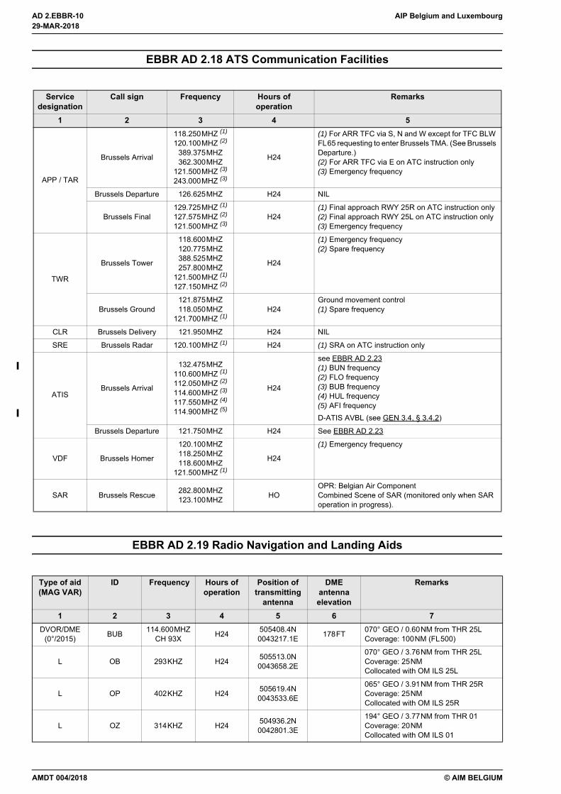
EBBR AD 2.18 ATS Communication Facilities
EBBR AD 2.19 Radio Navigation and Landing Aids
Service designation
Call sign Frequency Hours ofoperation
Remarks
1 2 3 4 5
APP / TAR
Brussels Arrival
118.250MHZ (1)
120.100MHZ (2)
389.375MHZ362.300MHZ
121.500MHZ (3)
243.000MHZ (3)
H24
(1) For ARR TFC via S, N and W except for TFC BLW FL65 requesting to enter Brussels TMA. (See Brussels Departure.) (2) For ARR TFC via E on ATC instruction only(3) Emergency frequency
Brussels Departure 126.625MHZ H24 NIL
Brussels Final129.725MHZ (1)
127.575MHZ (2)
121.500MHZ (3)H24
(1) Final approach RWY 25R on ATC instruction only(2) Final approach RWY 25L on ATC instruction only(3) Emergency frequency
TWR
Brussels Tower
118.600MHZ120.775MHZ388.525MHZ257.800MHZ
121.500MHZ (1)
127.150MHZ (2)
H24
(1) Emergency frequency(2) Spare frequency
Brussels Ground121.875MHZ118.050MHZ
121.700MHZ (1)H24
Ground movement control(1) Spare frequency
CLR Brussels Delivery 121.950MHZ H24 NIL
SRE Brussels Radar 120.100MHZ (1) H24 (1) SRA on ATC instruction only
ATISBrussels Arrival
132.475MHZ110.600MHZ (1)
112.050MHZ (2)
114.600MHZ (3)
117.550MHZ (4)
114.900MHZ (5)
H24
see EBBR AD 2.23(1) BUN frequency(2) FLO frequency(3) BUB frequency(4) HUL frequency(5) AFI frequencyD-ATIS AVBL (see GEN 3.4, § 3.4.2)
Brussels Departure 121.750MHZ H24 See EBBR AD 2.23
VDF Brussels Homer
120.100MHZ118.250MHZ118.600MHZ
121.500MHZ (1)
H24
(1) Emergency frequency
SAR Brussels Rescue 282.800MHZ123.100MHZ HO
OPR: Belgian Air Component Combined Scene of SAR (monitored only when SAR operation in progress).
Type of aid(MAG VAR)
ID Frequency Hours ofoperation
Position oftransmitting
antenna
DMEantennaelevation
Remarks
1 2 3 4 5 6 7DVOR/DME
(0°/2015) BUB 114.600MHZ CH 93X H24 505408.4N
0043217.1E 178FT 070° GEO / 0.60NM from THR 25LCoverage: 100NM (FL500)
L OB 293KHZ H24 505513.0N0043658.2E
070° GEO / 3.76NM from THR 25LCoverage: 25NM Collocated with OM ILS 25L
L OP 402KHZ H24 505619.4N0043533.6E
065° GEO / 3.91NM from THR 25RCoverage: 25NM Collocated with OM ILS 25R
L OZ 314KHZ H24 504936.2N0042801.3E
194° GEO / 3.77NM from THR 01Coverage: 20NM Collocated with OM ILS 01
29-MAR-2018
29-MAR-2018
AMDT 004/2018
AIP Belgium and Luxembourg AD 2.EBBR-11
© AIM BELGIUM
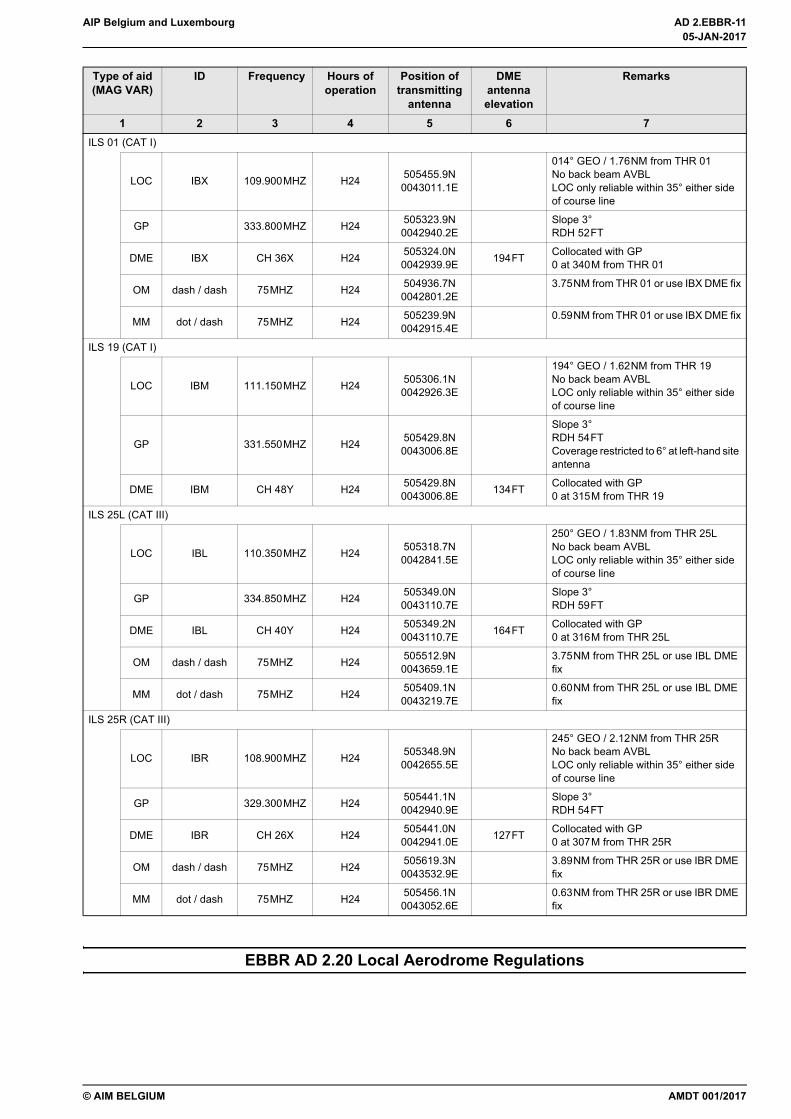
EBBR AD 2.20 Local Aerodrome Regulations
ILS 01 (CAT I)
LOC IBX 109.900MHZ H24 505455.9N0043011.1E
014° GEO / 1.76NM from THR 01No back beam AVBL LOC only reliable within 35° either side of course line
GP 333.800MHZ H24 505323.9N0042940.2E
Slope 3°RDH 52FT
DME IBX CH 36X H24 505324.0N0042939.9E 194FT Collocated with GP
0 at 340M from THR 01
OM dash / dash 75MHZ H24 504936.7N0042801.2E
3.75NM from THR 01 or use IBX DME fix
MM dot / dash 75MHZ H24 505239.9N0042915.4E
0.59NM from THR 01 or use IBX DME fix
ILS 19 (CAT I)
LOC IBM 111.150MHZ H24 505306.1N0042926.3E
194° GEO / 1.62NM from THR 19No back beam AVBL LOC only reliable within 35° either side of course line
GP 331.550MHZ H24 505429.8N0043006.8E
Slope 3°RDH 54FT Coverage restricted to 6° at left-hand site antenna
DME IBM CH 48Y H24 505429.8N0043006.8E 134FT Collocated with GP
0 at 315M from THR 19
ILS 25L (CAT III)
LOC IBL 110.350MHZ H24 505318.7N0042841.5E
250° GEO / 1.83NM from THR 25LNo back beam AVBL LOC only reliable within 35° either side of course line
GP 334.850MHZ H24 505349.0N0043110.7E
Slope 3°RDH 59FT
DME IBL CH 40Y H24 505349.2N0043110.7E 164FT Collocated with GP
0 at 316M from THR 25L
OM dash / dash 75MHZ H24 505512.9N0043659.1E
3.75NM from THR 25L or use IBL DME fix
MM dot / dash 75MHZ H24 505409.1N0043219.7E
0.60NM from THR 25L or use IBL DME fix
ILS 25R (CAT III)
LOC IBR 108.900MHZ H24 505348.9N0042655.5E
245° GEO / 2.12NM from THR 25RNo back beam AVBL LOC only reliable within 35° either side of course line
GP 329.300MHZ H24 505441.1N0042940.9E
Slope 3°RDH 54FT
DME IBR CH 26X H24 505441.0N0042941.0E 127FT Collocated with GP
0 at 307M from THR 25R
OM dash / dash 75MHZ H24 505619.3N0043532.9E
3.89NM from THR 25R or use IBR DME fix
MM dot / dash 75MHZ H24 505456.1N0043052.6E
0.63NM from THR 25R or use IBR DME fix
Type of aid(MAG VAR)
ID Frequency Hours ofoperation
Position oftransmitting
antenna
DMEantennaelevation
Remarks
1 2 3 4 5 6 7
AMDT 001/2017
05-JAN-2017
05-JAN-2017

AD 2.EBBR-12 AIP Belgium and Luxembourg
© AIM BELGIUM
1 GENERAL
1.1 Airport CoordinationEBBR is a coordinated airport. Unless exempted, and irrespective of noise abatement procedures (EBBR AD 2.21, § 1),ATFM slot, or traffic rights, take-off or landing of an IFR flight without an appropriate allocated slot is prohibited andpunishable. No airport slots will be allocated for take-off during following periods:
• SAT, 0000 (FRI, 2300) to SAT, 0500 (0400);• SAT, 2300 (2200) to SUN, 0500 (0400);• SUN, 2300 (2200) to MON, 0500 (0400).
1.1.1 Coordination Procedure
1.1.1.1 General
For every take-off and landing of an IFR flight, a slot shall be requested and obtained from the coordinator before the filingof the flight plan.
Applications should be made as early as possible. In case of short-term applications or alterations to flights, lower priorityhandling must be expected as against flights with earlier allocated slots for the same time of arrival or departure.
For fully coordinated airports, the arrival and departure times may only be published by the air carrier and/or operator afterallocation of the slots by the airport coordinator. The arrival and departure times at coordinated airports included in theannouncements and/or applications must conform to the airport slot as allocated by the airport slot coordinator.
Permission for entry and exit granted by the Belgian CAA does not replace the obligation to report or submit an applicationto the airport coordinator. The same applies to flight schedules for scheduled air services approved by the Belgian CAA.
Any unused slot shall be returned to the airport coordinator in due time.
1.1.1.2 Procedures for airlines
Slot applications shall be submitted via email to [email protected], whereby the procedures and formats of theIATA Standard Schedule Information Manual (SSIM, chapter 6), must be used.
1.1.1.3 Procedures for General Business Aviation (GA/BA)
Unless otherwise agreed with Belgium Slot Coordination (BSC), airport slots and airport slot authorization number must berequested only via a handling agent for General and Business Aviation. Slot requests sent directly to the coordinator willnot be accepted.
GA/BA flights outbound from or inbound for EBBR falling under this regulation shall fill item 18 of the flight plan form.
The filing format is as follows: RMK/ASL<authorization number>. The authorization number is that given by the coordinatorwhen allocating the airport time slot. It is composed of 14 alphanumeric characters, the first 4 of which are the ICAO codeof the airport for which the airport time slot has been delivered (example: “RMK/ASLEBBR1234567890”).
If the flight is between two coordinated airports applying a similar regulation (ex. France or Germany), the authorizationnumbers delivered by the coordinator for each airport shall be filled in, in item 18 as per the format below:RMK/ASLLFMNSEA3456789RMK/ASLEBBR1234567890
The general or business flight plans falling under this regulation and filed without authorization number or without acorresponding airport slot time, will not be taken in consideration for the departure sequence. For that purpose, a messagewill be sent by email by Brussels Airport Company on account of Belgium Slot Coordination to the flight plan originator orhis dedicated representative.
1.1.2 ExemptionsFollowing flights are exempted from coordination, but should be reported to the airport coordinator as far in advance aspossible:
• flights carrying members of the Belgian Royal Family, the Belgian governments or foreign royal families, foreignheads of state or leaders of governments, the President or commissioners of the European Commission when theyare on official mission;
• military missions.
Following flights are exempted from coordination, but should be reported to the airport coordinator as soon as possible afterthe operation:
• ILS calibration flights when urgently needed for operational reasons;• missions in case of disaster or medical urgency;• police emergency flights;• SAR flights;• landing (and subsequent departure within 2 hours) in case of operational diversion.
05-JAN-2017
05-JAN-2017
AMDT 001/2017
AIP Belgium and Luxembourg AD 2.EBBR-13
© AIM BELGIUM
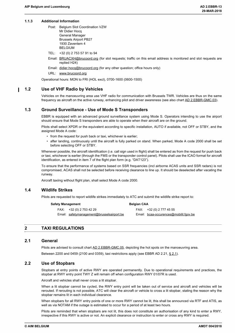
1.1.3 Additional InformationPost: Belgium Slot Coordination VZW
Mr Didier HocqGeneral ManagerBrussels Airport PB271930 Zaventem 4BELGIUM
TEL: +32 (0) 2 753 57 91 to 94Email: [email protected] (for slot requests; traffic on this email address is monitored and slot requests are
replied H24)Email: [email protected] (for any other question; office hours only)URL: www.brucoord.org
Operational hours: MON to FRI (HOL excl), 0700-1600 (0600-1500)
1.2 Use of VHF Radio by VehiclesVehicles on the manoeuvring area use VHF radio for communication with Brussels TWR. Vehicles are thus on the samefrequency as aircraft on the active runway, enhancing pilot and driver awareness (see also chart AD 2.EBBR-GMC.03).
1.3 Ground Surveillance - Use of Mode S TranspondersEBBR is equipped with an advanced ground surveillance system using Mode S. Operators intending to use the airportshould ensure that Mode S transponders are able to operate when their aircraft are on the ground.
Pilots shall select XPDR or the equivalent according to specific installation, AUTO if available, not OFF or STBY, and theassigned Mode A code:
• from the request for push back or taxi, whichever is earlier;• after landing, continuously until the aircraft is fully parked on stand. When parked, Mode A code 2000 shall be set
before selecting OFF or STBY.
Whenever possible, the aircraft identification (i.e. call sign used in flight) shall be entered as from the request for push backor taxi, whichever is earlier (through the FMS or the transponder control panel). Pilots shall use the ICAO format for aircraftidentification, as entered in item 7 of the flight plan form (e.g. “DAT123”).
To ensure that the performance of systems based on SSR frequencies (incl airborne ACAS units and SSR radars) is notcompromised, ACAS shall not be selected before receiving clearance to line up. It should be deselected after vacating therunway.
Aircraft taxiing without flight plan, shall select Mode A code 2000.
1.4 Wildlife StrikesPilots are requested to report wildlife strikes immediately to ATC and submit the wildlife strike report to:
2 TAXI REGULATIONS
2.1 GeneralPilots are advised to consult chart AD 2.EBBR-GMC.05, depicting the hot spots on the manoeuvring area.
Between 2200 and 0459 (2100 and 0359), taxi restrictions apply (see EBBR AD 2.21, § 2.1).
2.2 Use of StopbarsStopbars at entry points of active RWY are operated permanently. Due to operational requirements and practices, thestopbar at RWY entry point TWY Z will remain off when configuration RWY 01/07R is used.
Aircraft and vehicles shall never cross a lit stopbar.
When a lit stopbar cannot be cycled, the RWY entry point will be taken out of service and aircraft and vehicles will bererouted. If rerouting is not possible, ATC will clear the aircraft or vehicle to cross a lit stopbar, stating the reason why thestopbar remains lit in each individual clearance.
When stopbars for all RWY entry points of one or more RWY cannot be lit, this shall be announced via RTF and ATIS, aswell as via NOTAM if the outage is estimated to occur for a period of at least two hours.
Pilots are reminded that when stopbars are not lit, this does not constitute an authorisation of any kind to enter a RWY,irrespective if this RWY is active or not. An explicit clearance or instruction to enter or cross any RWY is required.
Safety Management Belgian CAAFAX: +32 (0) 2 753 42 29Email: [email protected]
FAX: +32 (0) 2 777 45 55Email: [email protected]
AMDT 004/2018
29-MAR-2018
29-MAR-2018

AD 2.EBBR-14 AIP Belgium and Luxembourg
© AIM BELGIUM
2.3 Standard Taxi Routes
2.3.1 GeneralAircraft requiring full length for departure shall advise GND at the latest when requesting taxi clearance.
Arriving aircraft shall remain on TWR frequency until instructed to contact GND.
Ground operations are controlled by two sectors: GND North and GND South (see chart AD 2.EBBR-GMC.03). Transfer ofcontrol and communication point between GND N and GND S is TWY INN 8 or OUT 8.
Aircraft will be transferred to the appropriate TWR frequency to enter or cross an active runway. An explicit clearance tocross or enter any runway shall be issued by ATC. If no such clearance is received, pilots shall obtain it from ATC beforecrossing the relevant holding position marking.
2.3.2 Runway Configuration 25L (Arrivals) / 25R (Departures)Departures originating from sector GND N will expect to depart from B1. Departures originating from sector GND S willexpect to depart from W41 or W42.
Clearance to cross RWY 01/19 at E4-F4, E5-F4 or E6-F5 may be given by GND. Aircraft arriving on RWY 25L andproceeding via E1 or E3 will receive clearance to cross RWY 01/19 from TWR.
2.3.3 Runway Configuration 25L and 25R (Arrivals) / 19 and 25R (Departures)All departures for RWY 25R will expect to depart from B1.
All departures for RWY 19 will expect to depart from E7.
Aircraft requiring full length for departure (RWY 19 and RWY 25R) will receive clearance to cross RWY 01/19 from TWR.
2.3.4 Runway Configuration 07L (Arrivals) / 07R (Departures)Departing traffic RWY 07R will receive take-off clearance on TWR FREQ 118.600 MHZ.
2.3.5 Runway Configuration 01 (Arrivals) / 07R (Departures)Traffic departing from RWY 07R, lining up via P9 and departing from position H or position 1, will receive line-up clearanceon GND S FREQ 121.875 MHZ.
Departing traffic will receive take-off clearance on TWR FREQ 120.775 MHZ.
2.3.6 LVPSee EBBR AD 2.22, § 4.1.2.
2.4 Taxiway RestrictionsWhen an A380 is present on TWY OUT, traffic on parallel TWY INN must be limited to Code D aircraft.
Pilots must not enter TWY W41 or W42 when A380 is present on TWY W41 or W42.
Pilots of A380 must not enter TWY W41 or W42 when another aircraft is present on TWY W41 or W42.
For A380 taxiway restrictions see chart AD 2.EBBR-GMC.06.
3 APRON REGULATIONS
3.1 Docking GuidanceWhen arriving at parking positions on remote stands or on stands where no guidance system is installed, pilots shall notenter the stand unless a marshaller is present for guidance. In case no marshaller is present, contact GND, requestmarshaller guidance and await the marshaller on the taxiway centre line.
Parking positions 140 to 174, 201 to 240, 350 to 354 and 680 to 699 are equipped with a docking guidance system.Guidance to these positions by marshallers may still be requested from GND.
29-MAR-2018
29-MAR-2018
AMDT 004/2018
AIP Belgium and Luxembourg AD 2.EBBR-15
© AIM BELGIUM
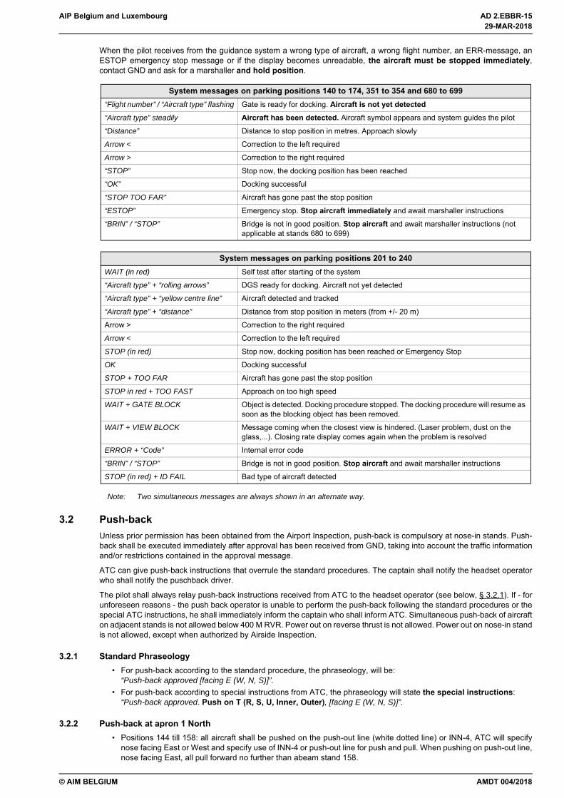
When the pilot receives from the guidance system a wrong type of aircraft, a wrong flight number, an ERR-message, anESTOP emergency stop message or if the display becomes unreadable, the aircraft must be stopped immediately,contact GND and ask for a marshaller and hold position.
Note: Two simultaneous messages are always shown in an alternate way.
3.2 Push-backUnless prior permission has been obtained from the Airport Inspection, push-back is compulsory at nose-in stands. Push-back shall be executed immediately after approval has been received from GND, taking into account the traffic informationand/or restrictions contained in the approval message.
ATC can give push-back instructions that overrule the standard procedures. The captain shall notify the headset operatorwho shall notify the puschback driver.
The pilot shall always relay push-back instructions received from ATC to the headset operator (see below, § 3.2.1). If - forunforeseen reasons - the push back operator is unable to perform the push-back following the standard procedures or thespecial ATC instructions, he shall immediately inform the captain who shall inform ATC. Simultaneous push-back of aircrafton adjacent stands is not allowed below 400 M RVR. Power out on reverse thrust is not allowed. Power out on nose-in standis not allowed, except when authorized by Airside Inspection.
3.2.1 Standard Phraseology• For push-back according to the standard procedure, the phraseology, will be:
“Push-back approved [facing E (W, N, S)]”.• For push-back according to special instructions from ATC, the phraseology will state the special instructions:
“Push-back approved. Push on T (R, S, U, Inner, Outer), [facing E (W, N, S)]”.
3.2.2 Push-back at apron 1 North• Positions 144 till 158: all aircraft shall be pushed on the push-out line (white dotted line) or INN-4, ATC will specify
nose facing East or West and specify use of INN-4 or push-out line for push and pull. When pushing on push-out line,nose facing East, all pull forward no further than abeam stand 158.
System messages on parking positions 140 to 174, 351 to 354 and 680 to 699“Flight number” / “Aircraft type” flashing Gate is ready for docking. Aircraft is not yet detected“Aircraft type” steadily Aircraft has been detected. Aircraft symbol appears and system guides the pilot
“Distance” Distance to stop position in metres. Approach slowly
Arrow < Correction to the left required
Arrow > Correction to the right required
“STOP” Stop now, the docking position has been reached
“OK” Docking successful
“STOP TOO FAR” Aircraft has gone past the stop position
“ESTOP” Emergency stop. Stop aircraft immediately and await marshaller instructions
“BRIN” / “STOP” Bridge is not in good position. Stop aircraft and await marshaller instructions (not applicable at stands 680 to 699)
System messages on parking positions 201 to 240WAIT (in red) Self test after starting of the system
“Aircraft type” + “rolling arrows” DGS ready for docking. Aircraft not yet detected
“Aircraft type” + “yellow centre line” Aircraft detected and tracked
“Aircraft type” + “distance” Distance from stop position in meters (from +/- 20 m)
Arrow > Correction to the right required
Arrow < Correction to the left required
STOP (in red) Stop now, docking position has been reached or Emergency Stop
OK Docking successful
STOP + TOO FAR Aircraft has gone past the stop position
STOP in red + TOO FAST Approach on too high speed
WAIT + GATE BLOCK Object is detected. Docking procedure stopped. The docking procedure will resume as soon as the blocking object has been removed.
WAIT + VIEW BLOCK Message coming when the closest view is hindered. (Laser problem, dust on the glass,...). Closing rate display comes again when the problem is resolved
ERROR + “Code” Internal error code
“BRIN” / “STOP” Bridge is not in good position. Stop aircraft and await marshaller instructions
STOP (in red) + ID FAIL Bad type of aircraft detected
AMDT 004/2018
29-MAR-2018
29-MAR-2018

AD 2.EBBR-16 AIP Belgium and Luxembourg
© AIM BELGIUM
3.2.3 Push-back at apron 1 South• Positions 143 and 145 L/R: all aircraft shall be pushed no further than stop point on TWY R4 (white perpendicular
mark on TWY).
3.2.4 Push-back at apron 2 North• Position 204: all aircraft shall be pushed on the push out line until stop point (white perpendicular mark on push out
line) and pulled forward until abeam stand 206L or further on ATC discretion.
3.2.5 Push-back at apron 2 South• Position 205 L: all aircraft shall be pushed backward with a slight turn to the right-hand side onto the push-out line.
Nose gear must be stopped on the stop position (white perpendicular mark on the push-out line). Aircraft will be pulledforward abeam stand 211. Full engine start only abeam stand 211.
• Position 205 R: • all aircraft shall be pushed on TWY T no further then stop point (white perpendicular mark on the TWY) and
pulled forward abeam stand 211, full engine start only abeam stand 211; or• all aircraft shall be pushed on TWY U and pulled forward abeam stand 316, full engine start only abeam stand
316.
3.2.6 Push-back at apron 3 North• ICAO aircraft category D or E shall be pushed onto taxiway T.• Position 312: all aircraft shall be pushed on TWY, nose facing West only.
Full engine start only abeam stand 211 (TWY T) / stand 316 (TWY U)
3.2.7 Push-back at apron 3 South• Position 313 and 315: ICAO aircraft category C with wingspan 36M MAX shall be pushed on the push-out line (white
dotted line). Nose gear shall be stopped on the stop point (white perpendicular mark on the push-out line).• Positions 317 until 327: all aircraft will be pushed on INN-9 or INN-10.
3.2.8 Push-back at satellite (apron 3)• Positions 351: all aircraft will be pushed on the push-out line (white dotted line). Nose gear shall be stopped on the
stop point (white perpendicular mark on the push-out line).• Positions 352, 353, 354 and 304: all aircraft will be pushed on taxiway INN, ATC will specify facing North or South.• Positions 306: all aircraft shall be pushed on TWY Z, ATC will specify facing East or West.
3.2.9 Push-back at apron 9• Position 950 and 951: all aircraft shall be pushed on TWY N1/N2 abeam position 958, nose facing West only.
In case of A380 push-back only allowed under supervision of Airside Inspection.• Position 952: for push back, nose facing West, all aircraft shall be pushed on TWY N1/N2 abeam position 958, nose
facing West only.• Position 971 and 972: for push back, nose facing West, All aircraft shall be pushed back on push out line via lead-in
line stand 973, nose gear no further than push out limit line (white perpendicular mark on lead-in line) and pulledforward abeam stand 971. Full engine start only abeam 971.
• Position 973: for push back, nose facing West, all aircraft shall be pushed on lead-in line stand 973, nose gear nofurther than push out limit line (white perpendicular mark on lead-in line) and pulled forward abeam stand 971, nosefacing West. Full engine start only abeam stand 971.
4 RUNWAY REGULATIONS
4.1 Selection of Runway-in-useThe direction in which aircraft take off and land is determined by the speed and direction of the surface wind or by thepreferential runway system.
The term “runway-in-use” is used to indicate the runway that - at a particular time - is considered by ATC to be the mostsuitable for use by the types of aircraft expected to land or take off according to the preferential runway system.
Normally, an aircraft will take off and land into the wind, unless safety, runway configuration or traffic conditions determinethat a different direction is preferable. However, in selecting the runway-in-use, ATC shall also take into consideration otherrelevant factors such as the aerodrome traffic circuits, the length of the runway, the approach and landing aids available,meteorological conditions, aircraft performance, the existence of a preferential runway system and noise abatement.
Accepting a runway is a pilot’s decision. If the pilot-in-command considers the runway-in-use not usable for reasons ofsafety or performance, he shall request permission to use another runway. ATC will accept such request, provided thattraffic and air safety conditions permit.
29-MAR-2018
29-MAR-2018
AMDT 004/2018
AIP Belgium and Luxembourg AD 2.EBBR-17
© AIM BELGIUM
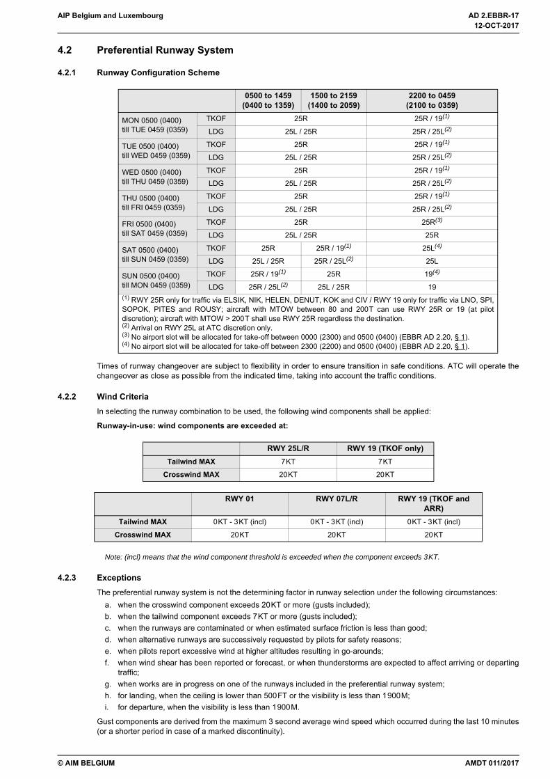
4.2 Preferential Runway System
4.2.1 Runway Configuration Scheme
Times of runway changeover are subject to flexibility in order to ensure transition in safe conditions. ATC will operate thechangeover as close as possible from the indicated time, taking into account the traffic conditions.
4.2.2 Wind CriteriaIn selecting the runway combination to be used, the following wind components shall be applied:
Runway-in-use: wind components are exceeded at:
Note: (incl) means that the wind component threshold is exceeded when the component exceeds 3KT.
4.2.3 ExceptionsThe preferential runway system is not the determining factor in runway selection under the following circumstances:
a. when the crosswind component exceeds 20KT or more (gusts included);b. when the tailwind component exceeds 7KT or more (gusts included);c. when the runways are contaminated or when estimated surface friction is less than good;d. when alternative runways are successively requested by pilots for safety reasons;e. when pilots report excessive wind at higher altitudes resulting in go-arounds;f. when wind shear has been reported or forecast, or when thunderstorms are expected to affect arriving or departing
traffic;g. when works are in progress on one of the runways included in the preferential runway system;h. for landing, when the ceiling is lower than 500FT or the visibility is less than 1900M;i. for departure, when the visibility is less than 1900M.
Gust components are derived from the maximum 3 second average wind speed which occurred during the last 10 minutes(or a shorter period in case of a marked discontinuity).
0500 to 1459(0400 to 1359)
1500 to 2159(1400 to 2059)
2200 to 0459(2100 to 0359)
MON 0500 (0400)till TUE 0459 (0359)
TKOF 25R 25R / 19(1)
LDG 25L / 25R 25R / 25L(2)
TUE 0500 (0400)till WED 0459 (0359)
TKOF 25R 25R / 19(1)
LDG 25L / 25R 25R / 25L(2)
WED 0500 (0400)till THU 0459 (0359)
TKOF 25R 25R / 19(1)
LDG 25L / 25R 25R / 25L(2)
THU 0500 (0400)till FRI 0459 (0359)
TKOF 25R 25R / 19(1)
LDG 25L / 25R 25R / 25L(2)
FRI 0500 (0400)till SAT 0459 (0359)
TKOF 25R 25R(3)
LDG 25L / 25R 25R
SAT 0500 (0400)till SUN 0459 (0359)
TKOF 25R 25R / 19(1) 25L(4)
LDG 25L / 25R 25R / 25L(2) 25L
SUN 0500 (0400)till MON 0459 (0359)
TKOF 25R / 19(1) 25R 19(4)
LDG 25R / 25L(2) 25L / 25R 19(1) RWY 25R only for traffic via ELSIK, NIK, HELEN, DENUT, KOK and CIV / RWY 19 only for traffic via LNO, SPI,SOPOK, PITES and ROUSY; aircraft with MTOW between 80 and 200T can use RWY 25R or 19 (at pilotdiscretion); aircraft with MTOW > 200T shall use RWY 25R regardless the destination.(2) Arrival on RWY 25L at ATC discretion only.(3) No airport slot will be allocated for take-off between 0000 (2300) and 0500 (0400) (EBBR AD 2.20, § 1).(4) No airport slot will be allocated for take-off between 2300 (2200) and 0500 (0400) (EBBR AD 2.20, § 1).
RWY 25L/R RWY 19 (TKOF only)Tailwind MAX 7KT 7KT
Crosswind MAX 20KT 20KT
RWY 01 RWY 07L/R RWY 19 (TKOF and ARR)
Tailwind MAX 0KT - 3KT (incl) 0KT - 3KT (incl) 0KT - 3KT (incl)
Crosswind MAX 20KT 20KT 20KT
AMDT 011/2017
12-OCT-2017
12-OCT-2017
AD 2.EBBR-18 AIP Belgium and Luxembourg
© AIM BELGIUM
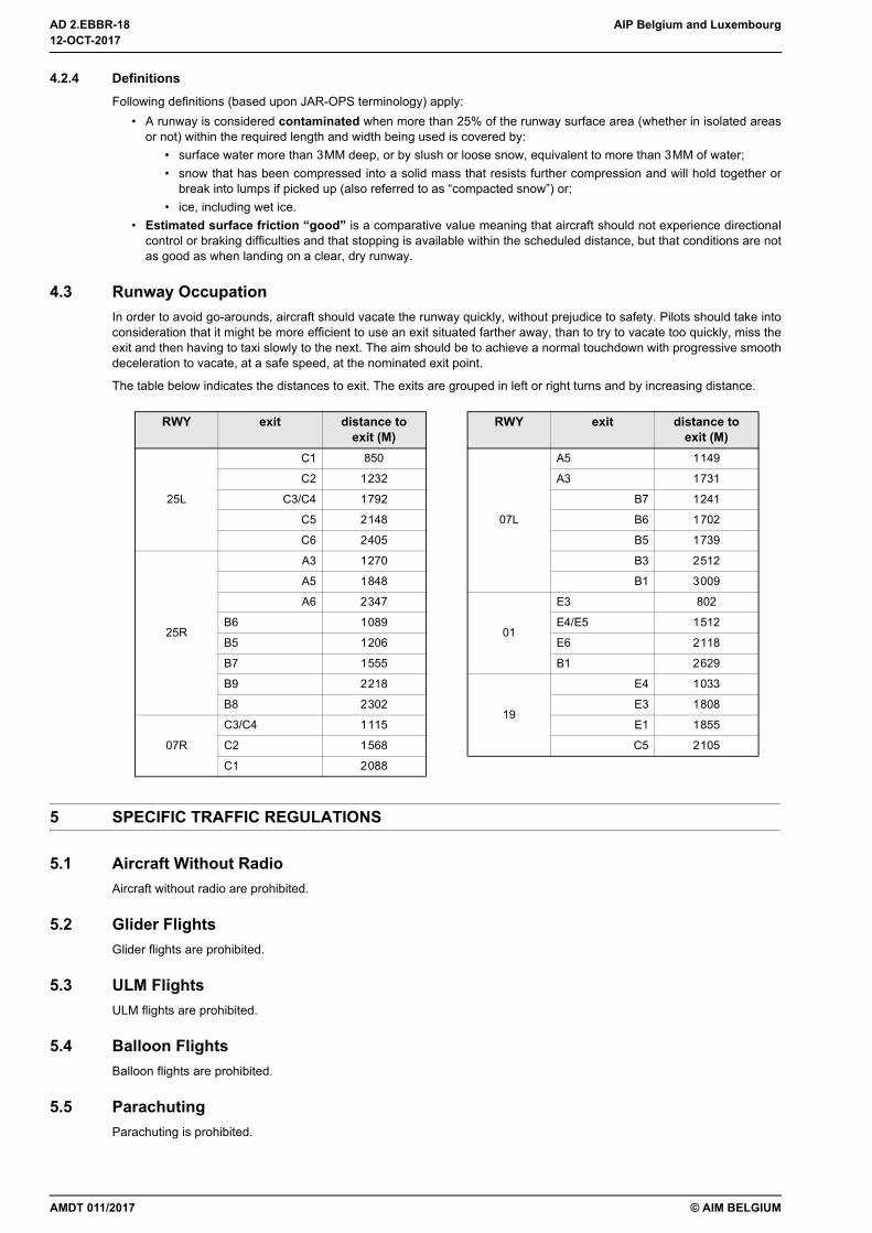
4.2.4 DefinitionsFollowing definitions (based upon JAR-OPS terminology) apply:
• A runway is considered contaminated when more than 25% of the runway surface area (whether in isolated areasor not) within the required length and width being used is covered by:
• surface water more than 3MM deep, or by slush or loose snow, equivalent to more than 3MM of water;• snow that has been compressed into a solid mass that resists further compression and will hold together or
break into lumps if picked up (also referred to as “compacted snow”) or;• ice, including wet ice.
• Estimated surface friction “good” is a comparative value meaning that aircraft should not experience directionalcontrol or braking difficulties and that stopping is available within the scheduled distance, but that conditions are notas good as when landing on a clear, dry runway.
4.3 Runway OccupationIn order to avoid go-arounds, aircraft should vacate the runway quickly, without prejudice to safety. Pilots should take intoconsideration that it might be more efficient to use an exit situated farther away, than to try to vacate too quickly, miss theexit and then having to taxi slowly to the next. The aim should be to achieve a normal touchdown with progressive smoothdeceleration to vacate, at a safe speed, at the nominated exit point.
The table below indicates the distances to exit. The exits are grouped in left or right turns and by increasing distance.
5 SPECIFIC TRAFFIC REGULATIONS
5.1 Aircraft Without RadioAircraft without radio are prohibited.
5.2 Glider FlightsGlider flights are prohibited.
5.3 ULM FlightsULM flights are prohibited.
5.4 Balloon FlightsBalloon flights are prohibited.
5.5 ParachutingParachuting is prohibited.
RWY exit distance toexit (M)
RWY exit distance toexit (M)
25L
C1 850
07L
A5 1149
C2 1232 A3 1731
C3/C4 1792 B7 1241
C5 2148 B6 1702
C6 2405 B5 1739
25R
A3 1270 B3 2512
A5 1848 B1 3009
A6 2347
01
E3 802
B6 1089 E4/E5 1512
B5 1206 E6 2118
B7 1555 B1 2629
B9 2218
19
E4 1033
B8 2302 E3 1808
07R
C3/C4 1115 E1 1855
C2 1568 C5 2105
C1 2088
12-OCT-2017
12-OCT-2017
AMDT 011/2017
AIP Belgium and Luxembourg AD 2.EBBR-19
© AIM BELGIUM
5.6 Acrobatic FlightsAcrobatic flights are prohibited.
5.7 Training and Test FlightsProvided traffic conditions permit, training and test flights may be performed using RWY 25L/R, outside following periods:
• 2200-0459 (2100-0359);• MON to FRI: 0600-1000 (0500-0900) and 1600-1900 (1500-1800);• SAT: 0700-1000 (0600-0900);• SUN: 1600-2000 (1500-1900).
Local VFR is not allowed during HN.
6 OPERATIONS OF LARGE AIRCRAFT
6.1 Aircraft Code FAircraft code F are subject to a special permission. However, B747-8F are authorised to operate at EBBR.
6.2 A380 Operations
6.2.1 GeneralOperators of A380 aircraft may designate Brussels Airport as a nominated diversionary aerodrome subject to prioragreement by Airside Inspection +32 2 753 69 00 and assessment of the handling facilities by the airline.
6.2.2 Aprons and Aircraft StandsDesignated aircraft stand 233L, equipped with triple apron boarding bridge and four power units.
Aircraft stands 951 and 954 suitable for remote handling. Push back from stand 951 only allowed under supervision ofAirside Inspection.
6.2.3 De-icingAircraft de-icing on stand, no remote de-icing area suitable.
EBBR AD 2.21 Noise Abatement Procedures
1 GENERAL
1.1 Noise RestrictionsMovements of jet aircraft with MTOW ≥ 34T or with a capacity of more than 19 seats (crew-only seats excl) are restricted:
• take-off or landing with QC > 8.0 is forbidden between 2200 and 0459 (2100 and 0359);• take-off or landing with QC > 12.0 is forbidden between 0500 and 0559 (0400 and 0459);• take-off with QC > 48.0 is forbidden between 0600 and 1959 (0500 and 1859);• landing with QC > 24.0 is forbidden between 0600 and 1959 (0500 and 1859);• take-off with QC > 24.0 is forbidden between 2000 and 2159 (1900 and 2059);• landing with QC > 12.0 is forbidden between 2000 and 2159 (1900 and 2059).
Exemptions may be granted for:• take-off between 2000 and 2159 (1900 and 2059) with QC ≤ 26.0 (with a maximum of 3% of the number of take-offs
per year for this time period);• take-off between 2200 and 0459 (2100 and 0359) with QC ≤ 12.0 (with a maximum of 200 take-offs per year only for
aircraft that operated at EBBR between 25 OCT 2008 and 24 OCT 2009);• landing between 2200 and 0459 (2100 and 0359) with QC ≤ 12.0 (with a maximum of 300 exemptions per year).
Exemptions shall be requested from the CAA in advance via FAX (+32 (0) 2 277 42 54) or via email([email protected]).
The QC is calculated using the formula QC = 10[(G-85)/10], whereby “G” equals:• for take-off: half the sum of the certified fly-over and sideline noise levels in EPNdB of the aircraft at its MTOW;• for landing: the certified approach noise level in EPNdB of the aircraft at its maximum landing weight, minus 9 EPNdB.
AMDT 004/2018
29-MAR-2018
29-MAR-2018
AD 2.EBBR-20 AIP Belgium and Luxembourg
© AIM BELGIUM
Take-off or landing of marginally compliant aircraft is forbidden between 2200 and 0459 (2100 and 0359).
Following flights are exempted from the noise quota system:• flights carrying members of the Belgian Royal Family, the federal government, regional or community governments
or foreign royal families, foreign heads of state or government leaders, the President or members of the EuropeanCommission on official mission;
• missions in case of disaster or medical urgency;• military missions;• take-off or landing performed in exceptional conditions (flights on which an immediate threat exists to the health of
people or animals, diverted flights, etc.).
In case of circumstances beyond the operator's control, a non-compliant flight may be exceptionally allowed, provided thatproper justification is sent to the Director-General of the CAA within two working days after the flight.
For marginally compliant aircraft, an authorization of temporary use may be delivered by the Minister of Transport or hisrepresentative, if the aircraft is operated exceptionally or in non-commercial flights for modifications, repairs ormaintenance.
1.2 Reverse ThrustExcept for safety reasons, reverse thrust shall not be used at other than idle power. On the aprons, it is prohibited at anytime.
2 GROUND PROCEDURES
2.1 Taxi Restrictions between 2200 and 0459 (2100 and 0359)Maximum four aircraft are authorized to taxi simultaneously to the holding position(s) of the runway(s)-in-use. Additionally,only three aircraft are allowed to await take-off clearance at the holding position at the same time.
Engine run-up is not allowed at the holding position, except for run-up tests performed immediately before take-off as partof the take-off procedure.
2.2 Engine Test Runs and Idle ChecksEngine test runs and idle checks in the open air and without silencers must be restricted to the very minimum and requireprior permission from the Airport Authority.
Engine test runs are only allowed between 0600 and 2100 (0500 and 2000). They can only take place on the crossing ofTWY F3, Y, W1 and W21. If this crossing is not available due to infrastructural reasons, compass swing located at TWY D2may be used instead.
2.3 Power SupplyThe aircraft parking positions 140 to 174, 201 to 240, 680 to 699 and 969 to 973 are equipped with 400HZ and aircraftparking positions 140 to 174, 201 to 240 and 680 to 699 are equipped with pre-conditioned air (PCA). As soon as possibleafter arrival at one of these positions (5MIN after docking MAX), 400HZ shall be connected and the APU switched off. Upondeparture (15MIN before ETD), the APU may be started and 400HZ shall be disconnected. When 400HZ or PCA is notavailable, GPU shall be used.
When no PCA is available and an authorization from the Airport Inspection has been obtained, the use of the APU is allowedduring periods of extreme high or low temperatures for aircraft docked for more than 1HR at the aircraft parking position.
3 ARRIVAL PROCEDURES
3.1 ILS ApproachAircraft performing an ILS approach shall not intercept the GP below:
• 2000FT QNH for RWY 25L/R (3000FT and 2000FT respectively in case of simultaneous approach);• 2000FT QNH for RWY 01;• 3000FT QNH for RWY 19.
After interception, the aircraft shall not descend below the GP.
3.2 Surveillance Radar ApproachAircraft performing an SRA without ILS assistance, shall not descend below 2000FT QNH before 6NM from touchdown,nor fly thereafter below a descent path of 3°.
29-MAR-2018
29-MAR-2018
AMDT 004/2018
AIP Belgium and Luxembourg AD 2.EBBR-21
© AIM BELGIUM
3.3 Visual ApproachAircraft performing a visual approach without ILS or radar assistance, shall not descend below 1800FT QNH beforeintercepting the PAPI approach slope, nor fly below it thereafter.
3.4 Vectored Continuous Descent Operations (CDO)When the traffic situation permits, ATC will facilitate vectored continuous descent for all RWY.
Facilitation of CDO will be provided at ATC discretion only.
When vectoring for continuous descent, ATC will, as soon as practicable after first call on the APP frequency, providedistance from touchdown and an approval to descend at pilot’s discretion. The phraseology “when ready, descend” shallbe used.
CDO will not be facilitated in adverse weather conditions that may affect the approach (wind shear, thunderstorms, etc).
Subject to ATC instructions, inbound aircraft shall adopt a continuous descent profile - to the greatest possible extentcompatible with safe operation of the aircraft - by employing minimum engine thrust, ideally in a low drag configuration, priorto the FAF/FAP.
Note: All noise abatement procedures for arrivals as well as the speed limitations in EBBR AD 2.22, § 2.1.3 remain applicable when performing CDO.
3.5 Speed LimitationAircraft being radar vectored shall reduce speed to 250KIAS when entering the radar vectoring area or when below FL100.250KIAS MAX shall be respected by all pilots as soon as they cross one of the speed limiting points (SLP) as shown onchart AD 2.EBBR-STAR.01.
3.6 Special Procedures for Arrivals between 2200 and 0459 (2100 and 0359)Traffic leaving IAF KERKY for approach to RWY 25L/R will not be cleared to descend below FL70 until crossing R-360 BUBunless for vectored continuous descent operations (see § 3.4 above).
4 DEPARTURE PROCEDURES
4.1 GeneralThe SID (see EBBR AD 2.22, § 3.2.1) constitute noise abatement procedures. It is therefore emphasized that pilots shalladhere to these routes as closely as performance permits. If unable to comply with these procedures, they shall advise ATCimmediately.
4.2 Climb GradientIn order to minimize noise nuisance, to clear obstacles in the departure area and for compliance with ATS airspace limits,aircraft shall maintain a net climb gradient of 7% MNM until passing 3200FT QNH. If unable to comply, pilots shall adviseATS accordingly when requesting start-up clearance.
4.3 Noise Abatement Take-off and Climb ProceduresThe following operational noise abatement take-off procedures must be applied for outbound flights:
For turbo-jet aircraft:• from take-off to 1700FT QNH:
• take-off power;• take-off flaps;• climb to V2 + 10 to 20KT or as limited by body angle;
• at 1700FT QNH:• reduce thrust to not less than climb thrust;
• from 1700FT QNH to 3200FT QNH:• climb at V2 + 10 to 20KT;
• at 3200FT QNH:• accelerate smoothly to en-route climb speed with flaps retraction.
For propeller aircraft:• from take-off to 1700FT QNH:
• take-off power;• climb at maximum gradient compatible with safety;• speed not less than single engine climb speed, nor higher than best rate of climb speed;
• at 1700FT QNH:
AMDT 004/2018
29-MAR-2018
29-MAR-2018
AD 2.EBBR-22 AIP Belgium and Luxembourg
© AIM BELGIUM
• reduce power to the maximum normal operating power (if this power has been used for showing compliancewith the noise certification requirements) or to the maximum climb power;
• from 1700FT QNH to 3200FT QNH:• climb at the maximum gradients with reduced power, maintaining constant speed;
• at 3200FT QNH:• accelerate smoothly to en-route climb speed.
4.4 Speed RestrictionsUnless otherwise instructed by ATC for safety reasons, maximum speed below FL100 is 250KIAS or clean speed (VZF),whichever is higher.
4.5 Special Procedures for Aircraft with MTOW > 200TWhen preferential runway system configuration RWY 25R/19 is in use for departures, the following aircraft shall use RWY25R for departure, regardless of their destination.
4.6 Special Procedures for Departures between 2200 and 0459 (2100 and 0359)All departures from RWY 25R shall start their take-off at the beginning of the runway and preferably an uninterrupted take-off from W41/W42 will be made.
EBBR AD 2.22 Flight Procedures
1 GENERAL
1.1 Aerodrome MinimaFor specific landing minima, see charts:
• AD 2.EBBR-IAC.01• AD 2.EBBR-IAC.02• AD 2.EBBR-IAC.08• AD 2.EBBR-IAC.09• AD 2.EBBR-IAC.10
2 IFR FLIGHTS (INBOUND)
2.1 General
2.1.1 Aircraft EquipmentDME is compulsory for all inbound IFR traffic.
2.1.2 Radar VectoringRadar vectoring may be expected when crossing 30 DME BUB.
In case of radar vectoring, the intermediate approach procedure may be partially or completely omitted. The clearance limitassigned by Brussels ACC will then be replaced by a clearance to a final approach aid or radar vectors will be given to directthe aircraft to a position from where final approach can be started or a visual approach made.
2.1.3 Speed LimitationsIn case of ILS approach following speed limits apply, unless otherwise instructed by ATC:
• 250KIAS below FL100;• 220KIAS or more from IAF until LOC interception;
ICAO aircraft type (see ICAO Doc 8643)A124 A332 A333 A342 A343 A345 A346
A388 AN22 B741 B742 B743 B744 B748
B74R B74S B764 B772 B773 B77L B77W
B788 C5 C17 DC10 IL96 L101 MD11
29-MAR-2018
29-MAR-2018
AMDT 004/2018

AIP Belgium and Luxembourg AD 2.EBBR-23
© AIM BELGIUM
• 180KIAS or more at a distance of approximately 12NM from touchdown until 6NM from touchdown;• 160KIAS until OM (or 4NM from THR RWY 19)1.
Aircraft unable to maintain these speeds shall advice Brussels Arrival/Final on initial contact.
The speed limitations do not relieve pilots of their responsibility to observe any applicable noise abatement procedures (seeEBBR AD 2.21).
(1) Aircraft unable to maintain 160KIAS until OM (or 4NM from THR RWY 19) will not be accepted during periods 0700-0900 (0600-0800) and 1700-1930 (1600-1830) ATA.
2.2 Holding PatternsThe holding patterns shall be entered at 170KIAS MAX (aircraft CAT A/B) or 230KIAS MAX (aircraft CAT C/D).
ANTWERPENFix ANT DVOR/DME
Turn / inbound track (MAG) Left / 117°
Levels (MAX / MNM) FL140 / FL80
Remarks NIL
BRUNOFix BUN DVOR/DME
Turn / inbound track (MAG) Right / 115°
Levels (MAX / MNM) FL140 / 3000FT QNH
Remarks At ATC discretion only
FLORAFix FLO DVOR/DME
Turn / inbound track (MAG) Right / 308°
Levels (MAX / MNM) FL140 / FL90 (FL60 when RWY 25R/L is used for landings
Remarks NIL
GOSLYFix GSY DVOR/DME
Turn / inbound track (MAG) Left / 358°
Levels (MAX / MNM) FL230 / FL100
Remarks At ATC discretion only
KERKYFix KERKY (R-282 AFI/5.7NM and R-207 NIK/16.0NM)
Turn / inbound track (MAG) Right / 100°
Levels (MAX / MNM) FL90 / 4000FT QNH
Remarks NIL
NIVORFix NIVOR (R-156 AFI/14.0NM and R-256 HUL/13.7NM)
Turn / inbound track (MAG) Left / 075°
Levels (MAX / MNM) FL90 / 3000FT QNH
Remarks At ATC discretion only
AMDT 004/2018
29-MAR-2018
29-MAR-2018
AD 2.EBBR-24 AIP Belgium and Luxembourg
© AIM BELGIUM
2.3 Approach Procedures
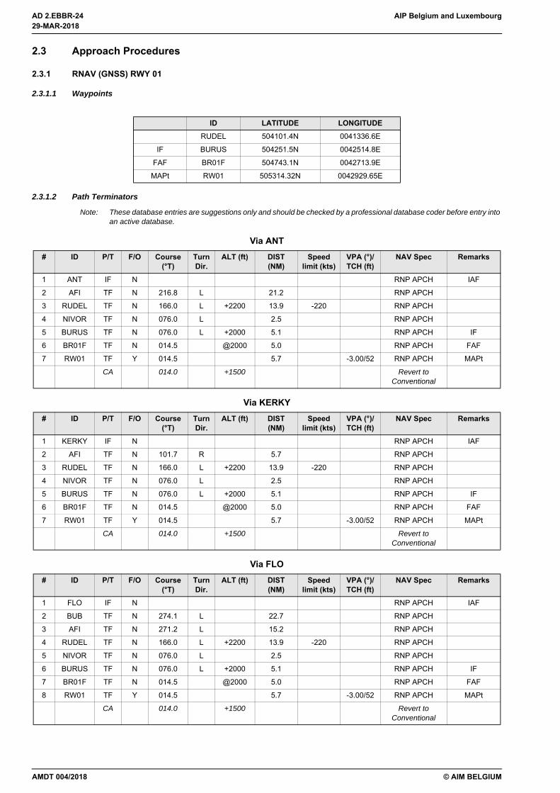
2.3.1 RNAV (GNSS) RWY 01
2.3.1.1 Waypoints
2.3.1.2 Path Terminators
Note: These database entries are suggestions only and should be checked by a professional database coder before entry into an active database.
ID LATITUDE LONGITUDERUDEL 504101.4N 0041336.6E
IF BURUS 504251.5N 0042514.8E
FAF BR01F 504743.1N 0042713.9E
MAPt RW01 505314.32N 0042929.65E
Via ANT# ID P/T F/O Course
(°T)Turn Dir.
ALT (ft) DIST (NM)
Speed limit (kts)
VPA (°)/TCH (ft)
NAV Spec Remarks
1 ANT IF N RNP APCH IAF
2 AFI TF N 216.8 L 21.2 RNP APCH
3 RUDEL TF N 166.0 L +2200 13.9 -220 RNP APCH
4 NIVOR TF N 076.0 L 2.5 RNP APCH
5 BURUS TF N 076.0 L +2000 5.1 RNP APCH IF
6 BR01F TF N 014.5 @2000 5.0 RNP APCH FAF
7 RW01 TF Y 014.5 5.7 -3.00/52 RNP APCH MAPt
CA 014.0 +1500 Revert to Conventional
Via KERKY# ID P/T F/O Course
(°T)Turn Dir.
ALT (ft) DIST (NM)
Speed limit (kts)
VPA (°)/TCH (ft)
NAV Spec Remarks
1 KERKY IF N RNP APCH IAF
2 AFI TF N 101.7 R 5.7 RNP APCH
3 RUDEL TF N 166.0 L +2200 13.9 -220 RNP APCH
4 NIVOR TF N 076.0 L 2.5 RNP APCH
5 BURUS TF N 076.0 L +2000 5.1 RNP APCH IF
6 BR01F TF N 014.5 @2000 5.0 RNP APCH FAF
7 RW01 TF Y 014.5 5.7 -3.00/52 RNP APCH MAPt
CA 014.0 +1500 Revert to Conventional
Via FLO# ID P/T F/O Course
(°T)Turn Dir.
ALT (ft) DIST (NM)
Speed limit (kts)
VPA (°)/TCH (ft)
NAV Spec Remarks
1 FLO IF N RNP APCH IAF
2 BUB TF N 274.1 L 22.7 RNP APCH
3 AFI TF N 271.2 L 15.2 RNP APCH
4 RUDEL TF N 166.0 L +2200 13.9 -220 RNP APCH
5 NIVOR TF N 076.0 L 2.5 RNP APCH
6 BURUS TF N 076.0 L +2000 5.1 RNP APCH IF
7 BR01F TF N 014.5 @2000 5.0 RNP APCH FAF
8 RW01 TF Y 014.5 5.7 -3.00/52 RNP APCH MAPt
CA 014.0 +1500 Revert to Conventional
29-MAR-2018
29-MAR-2018
AMDT 004/2018
AIP Belgium and Luxembourg AD 2.EBBR-25
© AIM BELGIUM
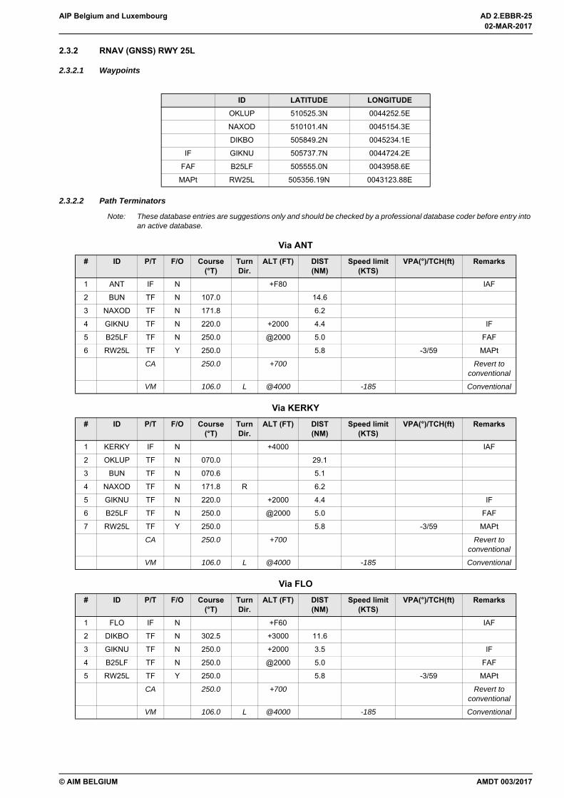
2.3.2 RNAV (GNSS) RWY 25L
2.3.2.1 Waypoints
2.3.2.2 Path Terminators
Note: These database entries are suggestions only and should be checked by a professional database coder before entry into an active database.
ID LATITUDE LONGITUDEOKLUP 510525.3N 0044252.5E
NAXOD 510101.4N 0045154.3E
DIKBO 505849.2N 0045234.1E
IF GIKNU 505737.7N 0044724.2E
FAF B25LF 505555.0N 0043958.6E
MAPt RW25L 505356.19N 0043123.88E
Via ANT# ID P/T F/O Course
(°T)Turn Dir.
ALT (FT) DIST (NM)
Speed limit (KTS)
VPA(°)/TCH(ft) Remarks
1 ANT IF N +F80 IAF
2 BUN TF N 107.0 14.6
3 NAXOD TF N 171.8 6.2
4 GIKNU TF N 220.0 +2000 4.4 IF
5 B25LF TF N 250.0 @2000 5.0 FAF
6 RW25L TF Y 250.0 5.8 -3/59 MAPt
CA 250.0 +700 Revert to conventional
VM 106.0 L @4000 -185 Conventional
Via KERKY# ID P/T F/O Course
(°T)Turn Dir.
ALT (FT) DIST (NM)
Speed limit (KTS)
VPA(°)/TCH(ft) Remarks
1 KERKY IF N +4000 IAF
2 OKLUP TF N 070.0 29.1
3 BUN TF N 070.6 5.1
4 NAXOD TF N 171.8 R 6.2
5 GIKNU TF N 220.0 +2000 4.4 IF
6 B25LF TF N 250.0 @2000 5.0 FAF
7 RW25L TF Y 250.0 5.8 -3/59 MAPt
CA 250.0 +700 Revert to conventional
VM 106.0 L @4000 -185 Conventional
Via FLO# ID P/T F/O Course
(°T)Turn Dir.
ALT (FT) DIST (NM)
Speed limit (KTS)
VPA(°)/TCH(ft) Remarks
1 FLO IF N +F60 IAF
2 DIKBO TF N 302.5 +3000 11.6
3 GIKNU TF N 250.0 +2000 3.5 IF
4 B25LF TF N 250.0 @2000 5.0 FAF
5 RW25L TF Y 250.0 5.8 -3/59 MAPt
CA 250.0 +700 Revert to conventional
VM 106.0 L @4000 -185 Conventional
AMDT 003/2017
02-MAR-2017
02-MAR-2017

AD 2.EBBR-26 AIP Belgium and Luxembourg
© AIM BELGIUM
2.3.3 RNAV (GNSS) RWY 25R
2.3.3.1 Waypoints
2.3.3.2 Path Terminators
Note: These database entries are suggestions only and should be checked by a professional database coder before entry into an active database.
2.3.4 Standard Instrument ArrivalsSTAR have been established as shown on the STAR charts (see EBBR AD 2.24) and as listed below. ATC may deviatefrom these routes and pilots may expect radar vectors for separation reasons or in order to expedite traffic flow.
ID LATITUDE LONGITUDEOKLUP 510525.3N 0044252.5E
NAXOD 510101.4N 0045154.3E
DIKBO 505849.2N 0045234.1E
IF UVETI 505914.0N 0044541.9E
FAF B25RF 505709.5N 0043830.2E
MAPt RW25R 505441.55N 0042957.79E
Via ANT# ID P/T F/O Course
(°T)Turn Dir.
ALT (FT) DIST (NM)
Speed limit (KTS)
VPA(°)/TCH(ft) Remarks
1 ANT IF N +F80 IAF
2 BUN TF N 107.0 14.6
3 NAXOD TF N 171.8 6.2
4 UVETI TF N 245.5 +2000 4.3 IF
5 B25RF TF N 245.5 @2000 5.0 FAF
6 RW25R TF Y 245.5 5.9 -3/54 MAPt
CA 245.5 +700 Revert to conventional
VM 016.0 R @3000 Conventional
Via KERKY# ID P/T F/O Course
(°T)Turn Dir.
ALT (FT) DIST (NM)
Speed limit (KTS)
VPA(°)/TCH(ft) Remarks
1 KERKY IF N +4000 IAF
2 OKLUP TF N 070.0 29.1
3 BUN TF N 070.6 5.1
4 NAXOD TF N 171.8 R 6.2
5 UVETI TF N 245.5 +2000 4.3 IF
6 B25RF TF N 245.5 @2000 5.0 FAF
7 RW25R TF Y 245.5 5.9 -3/54 MAPt
CA 245.5 +700 Revert to conventional
VM 016.0 R @3000 Conventional
Via FLO# ID P/T F/O Course
(°T)Turn Dir.
ALT (FT) DIST (NM)
Speed limit (KTS)
VPA(°)/TCH(ft) Remarks
1 FLO IF N +F60 IAF
2 DIKBO TF N 302.5 +3000 11.6
3 UVETI TF N 275.5 +2000 4.4 IF
4 B25RF TF N 245.5 @2000 5.0 FAF
5 RW25R TF Y 245.5 5.9 -3/54 MAPt
CA 245.5 +700 Revert to conventional
VM 016.0 R @3000 Conventional
02-MAR-2017
02-MAR-2017
AMDT 003/2017
AIP Belgium and Luxembourg AD 2.EBBR-27
© AIM BELGIUM
Depending on traffic conditions (LVP in progress, etc.), ATC may clear traffic to hold at GSY DVOR/DME. At EAT, suchtraffic will be re-cleared for a standard approach or will be radar vectored for sequencing.
AIRAC AMDT 002/2017
02-MAR-2017
02-MAR-2017
AD 2.EBBR-28 AIP Belgium and Luxembourg
© AIM BELGIUM
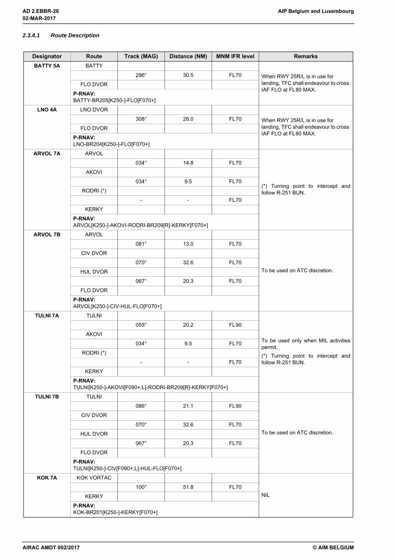
2.3.4.1 Route Description
Designator Route Track (MAG) Distance (NM) MNM IFR level RemarksBATTY 5A BATTY
When RWY 25R/L is in use for landing, TFC shall endeavour to cross IAF FLO at FL80 MAX.
296° 30.5 FL70
FLO DVOR
P-RNAV:BATTY-BR205[K250-]-FLO[F070+]
LNO 4A LNO DVOR
When RWY 25R/L is in use for landing, TFC shall endeavour to cross IAF FLO at FL80 MAX.
308° 28.0 FL70
FLO DVOR
P-RNAV:LNO-BR204[K250-]-FLO[F070+]
ARVOL 7A ARVOL
(*) Turning point to intercept andfollow R-251 BUN.
034° 14.8 FL70
AKOVI
034° 9.5 FL70
RODRI (*)
- - FL70
KERKY
P-RNAV:ARVOL[K250-]-AKOVI-RODRI-BR209[R]-KERKY[F070+]
ARVOL 7B ARVOL
To be used on ATC discretion.
081° 13.0 FL70
CIV DVOR
070° 32.6 FL70
HUL DVOR
067° 20.3 FL70
FLO DVOR
P-RNAV:ARVOL[K250-]-CIV-HUL-FLO[F070+]
TULNI 7A TULNI
To be used only when MIL activitiespermit.(*) Turning point to intercept andfollow R-251 BUN.
055° 20.2 FL90
AKOVI
034° 9.5 FL70
RODRI (*)
- - FL70
KERKY
P-RNAV:TULNI[K250-]-AKOVI[F090+;L]-RODRI-BR209[R]-KERKY[F070+]
TULNI 7B TULNI
To be used on ATC discretion.
086° 21.1 FL90
CIV DVOR
070° 32.6 FL70
HUL DVOR
067° 20.3 FL70
FLO DVOR
P-RNAV:TULNI[K250-]-CIV[F090+;L]-HUL-FLO[F070+]
KOK 7A KOK VORTAC
NIL100° 51.8 FL70
KERKY
P-RNAV:KOK-BR201[K250-]-KERKY[F070+]
02-MAR-2017
02-MAR-2017
AIRAC AMDT 002/2017

AIP Belgium and Luxembourg AD 2.EBBR-29
© AIM BELGIUM
WOODY 7A WOODY
NIL
205° 7.6 FL70
8.4 DME NIK
117° - FL70
ANT DVOR
P-RNAV:WOODY[K250-]-BR202[L]-ANT[F070+]
WOODY 3B WOODY
To be used on ATC discretion.
205° 16.0 FL80
NIK
206° 16.0 FL80
KERKY
P-RNAV:WOODY[K250-]-NIK-KERKY[F080+]
BEKEM 7A BEKEM
NIL
222° 13.2 FL70
8.7 DME NIK
117° - FL70
ANT DVOR
P-RNAV:BEKEM[K250-]-BR203[L]-ANT[F070+]
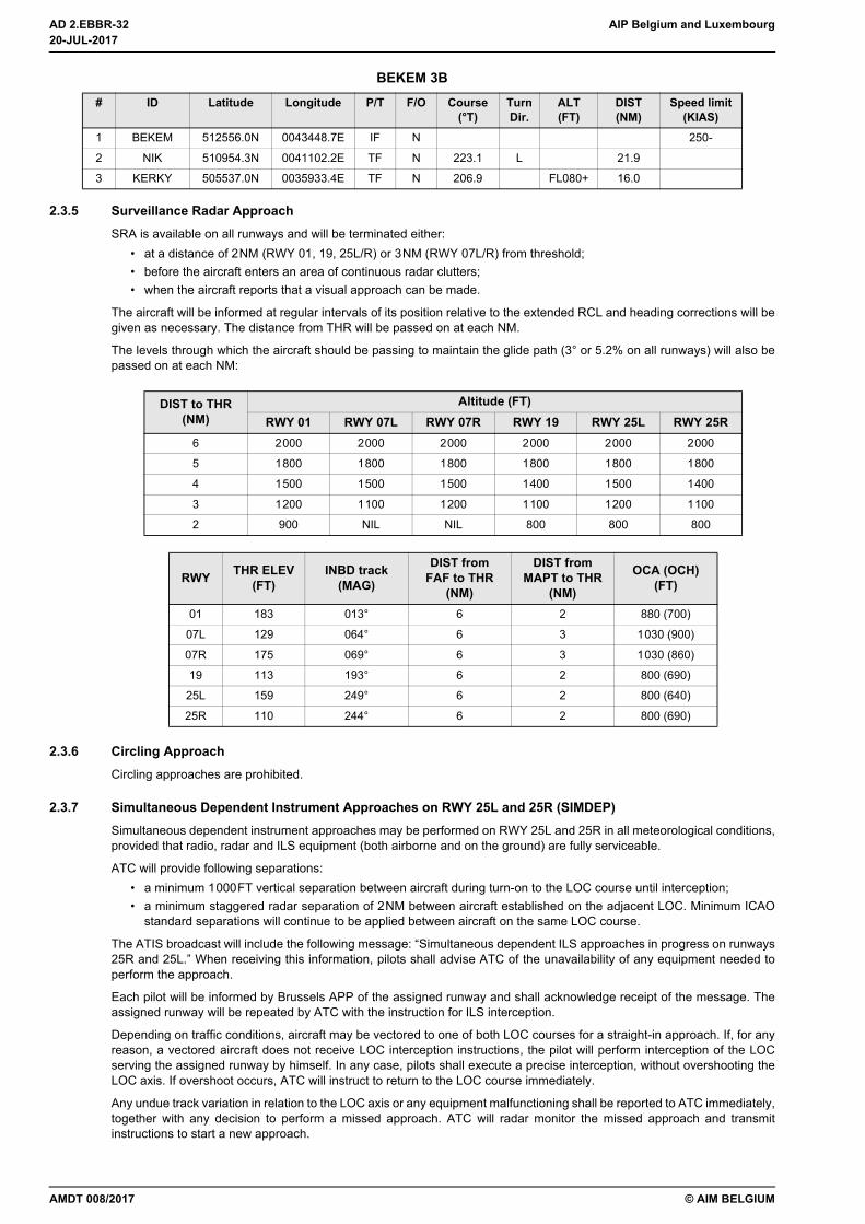
BEKEM 3B BEKEM
To be used on ATC discretion.
222° 21.9 FL80
NIK
206° 16.0 FL80
KERKY
P-RNAV:BEKEM[K250-]-NIK[L]-KERKY[F080+]
Designator Route Track (MAG) Distance (NM) MNM IFR level Remarks
AIRAC AMDT 002/2017
02-MAR-2017
02-MAR-2017
AD 2.EBBR-30 AIP Belgium and Luxembourg
© AIM BELGIUM
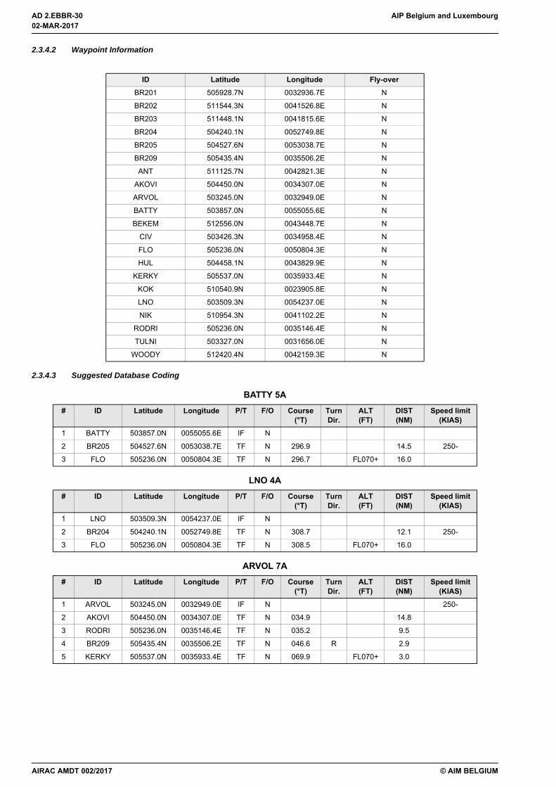
2.3.4.2 Waypoint Information
2.3.4.3 Suggested Database Coding
ID Latitude Longitude Fly-overBR201 505928.7N 0032936.7E N
BR202 511544.3N 0041526.8E N
BR203 511448.1N 0041815.6E N
BR204 504240.1N 0052749.8E N
BR205 504527.6N 0053038.7E N
BR209 505435.4N 0035506.2E N
ANT 511125.7N 0042821.3E N
AKOVI 504450.0N 0034307.0E N
ARVOL 503245.0N 0032949.0E N
BATTY 503857.0N 0055055.6E N
BEKEM 512556.0N 0043448.7E N
CIV 503426.3N 0034958.4E N
FLO 505236.0N 0050804.3E N
HUL 504458.1N 0043829.9E N
KERKY 505537.0N 0035933.4E N
KOK 510540.9N 0023905.8E N
LNO 503509.3N 0054237.0E N
NIK 510954.3N 0041102.2E N
RODRI 505236.0N 0035146.4E N
TULNI 503327.0N 0031656.0E N
WOODY 512420.4N 0042159.3E N
BATTY 5A# ID Latitude Longitude P/T F/O Course
(°T)Turn Dir.
ALT (FT)
DIST (NM)
Speed limit (KIAS)
1 BATTY 503857.0N 0055055.6E IF N
2 BR205 504527.6N 0053038.7E TF N 296.9 14.5 250-
3 FLO 505236.0N 0050804.3E TF N 296.7 FL070+ 16.0
LNO 4A# ID Latitude Longitude P/T F/O Course
(°T)Turn Dir.
ALT (FT)
DIST (NM)
Speed limit (KIAS)
1 LNO 503509.3N 0054237.0E IF N
2 BR204 504240.1N 0052749.8E TF N 308.7 12.1 250-
3 FLO 505236.0N 0050804.3E TF N 308.5 FL070+ 16.0
ARVOL 7A# ID Latitude Longitude P/T F/O Course
(°T)Turn Dir.
ALT (FT)
DIST (NM)
Speed limit (KIAS)
1 ARVOL 503245.0N 0032949.0E IF N 250-
2 AKOVI 504450.0N 0034307.0E TF N 034.9 14.8
3 RODRI 505236.0N 0035146.4E TF N 035.2 9.5
4 BR209 505435.4N 0035506.2E TF N 046.6 R 2.9
5 KERKY 505537.0N 0035933.4E TF N 069.9 FL070+ 3.0
02-MAR-2017
02-MAR-2017
AIRAC AMDT 002/2017

AIP Belgium and Luxembourg AD 2.EBBR-31
© AIM BELGIUM
ARVOL 7B# ID Latitude Longitude P/T F/O Course
(°T)Turn Dir.
ALT (FT)
DIST (NM)
Speed limit (KIAS)
1 ARVOL 503245.0N 0032949.0E IF N 250-
2 CIV 503426.3N 0034958.4E TF N 082.4 13.0
3 HUL 504458.1N 0043829.9E TF N 070.8 32.6
4 FLO 505236.0N 0050804.3E TF N 067.7 FL070+ 20.3
TULNI 7A# ID Latitude Longitude P/T F/O Course
(°T)Turn Dir.
ALT (FT)
DIST (NM)
Speed limit (KIAS)
1 TULNI 503327.0N 0031656.0E IF N 250-
2 AKOVI 504450.0N 0034307.0E TF N 055.5 L FL090+ 20.2
3 RODRI 505236.0N 0035146.4E TF N 035.2 9.5
4 BR209 505435.4N 0035506.2E TF N 046.6 R 2.9
5 KERKY 505537.0N 0035933.4E TF N 069.9 FL070+ 3.0
TULNI 7B# ID Latitude Longitude P/T F/O Course
(°T)Turn Dir.
ALT (FT)
DIST (NM)
Speed limit (KIAS)
1 TULNI 503327.0N 0031656.0E IF N 250-
2 CIV 503426.3N 0034958.4E TF N 087.3 L FL090+ 21.1
3 HUL 504458.1N 0043829.9E TF N 070.8 32.6
4 FLO 505236.0N 0050804.3E TF N 067.7 FL070+ 20.3
KOK 7A# ID Latitude Longitude P/T F/O Course
(°T)Turn Dir.
ALT (FT)
DIST (NM)
Speed limit (KIAS)
1 KOK 510540.9N 0023905.8E IF N
2 BR201 505928.7N 0032936.7E TF N 100.7 32.5 250-
3 KERKY 505537.0N 0035933.4E TF N 101.4 FL070+ 19.3
WOODY 7A# ID Latitude Longitude P/T F/O Course
(°T)Turn Dir.
ALT (FT)
DIST (NM)
Speed limit (KIAS)
1 WOODY 512420.4N 0042159.3E IF N 250-
2 BR202 511544.3N 0041526.8E TF N 205.5 L 9.5
3 ANT 511125.7N 0042821.3E TF N 117.9 FL070+ 9.2
WOODY 3B# ID Latitude Longitude P/T F/O Course
(°T)Turn Dir.
ALT (FT)
DIST (NM)
Speed limit (KIAS)
1 WOODY 512420.4N 0042159.3E IF N 250-
2 NIK 510954.3N 0041102.2E TF N 205.5 16.0
3 KERKY 505537.0N 0035933.4E TF N 206.9 FL080+ 16.0
BEKEM 7A# ID Latitude Longitude P/T F/O Course
(°T)Turn Dir.
ALT (FT)
DIST (NM)
Speed limit (KIAS)
1 BEKEM 512556.0N 0043448.7E IF N 250-
2 BR203 511448.1N 0041815.6E TF N 223.1 L 15.2
3 ANT 511125.7N 0042821.3E TF N 118.0 FL070+ 7.2
AMDT 008/2017
20-JUL-2017
20-JUL-2017
AD 2.EBBR-32 AIP Belgium and Luxembourg
© AIM BELGIUM
2.3.5 Surveillance Radar ApproachSRA is available on all runways and will be terminated either:
• at a distance of 2NM (RWY 01, 19, 25L/R) or 3NM (RWY 07L/R) from threshold;• before the aircraft enters an area of continuous radar clutters;• when the aircraft reports that a visual approach can be made.
The aircraft will be informed at regular intervals of its position relative to the extended RCL and heading corrections will begiven as necessary. The distance from THR will be passed on at each NM.
The levels through which the aircraft should be passing to maintain the glide path (3° or 5.2% on all runways) will also bepassed on at each NM:
2.3.6 Circling ApproachCircling approaches are prohibited.
2.3.7 Simultaneous Dependent Instrument Approaches on RWY 25L and 25R (SIMDEP)Simultaneous dependent instrument approaches may be performed on RWY 25L and 25R in all meteorological conditions,provided that radio, radar and ILS equipment (both airborne and on the ground) are fully serviceable.
ATC will provide following separations:• a minimum 1000FT vertical separation between aircraft during turn-on to the LOC course until interception;• a minimum staggered radar separation of 2NM between aircraft established on the adjacent LOC. Minimum ICAO
standard separations will continue to be applied between aircraft on the same LOC course.
The ATIS broadcast will include the following message: “Simultaneous dependent ILS approaches in progress on runways25R and 25L.” When receiving this information, pilots shall advise ATC of the unavailability of any equipment needed toperform the approach.
Each pilot will be informed by Brussels APP of the assigned runway and shall acknowledge receipt of the message. Theassigned runway will be repeated by ATC with the instruction for ILS interception.
Depending on traffic conditions, aircraft may be vectored to one of both LOC courses for a straight-in approach. If, for anyreason, a vectored aircraft does not receive LOC interception instructions, the pilot will perform interception of the LOCserving the assigned runway by himself. In any case, pilots shall execute a precise interception, without overshooting theLOC axis. If overshoot occurs, ATC will instruct to return to the LOC course immediately.
Any undue track variation in relation to the LOC axis or any equipment malfunctioning shall be reported to ATC immediately,together with any decision to perform a missed approach. ATC will radar monitor the missed approach and transmitinstructions to start a new approach.
BEKEM 3B# ID Latitude Longitude P/T F/O Course
(°T)Turn Dir.
ALT (FT)
DIST (NM)
Speed limit (KIAS)
1 BEKEM 512556.0N 0043448.7E IF N 250-
2 NIK 510954.3N 0041102.2E TF N 223.1 L 21.9
3 KERKY 505537.0N 0035933.4E TF N 206.9 FL080+ 16.0
DIST to THR(NM)
Altitude (FT) RWY 01 RWY 07L RWY 07R RWY 19 RWY 25L RWY 25R
6 2000 2000 2000 2000 2000 2000
5 1800 1800 1800 1800 1800 1800
4 1500 1500 1500 1400 1500 1400
3 1200 1100 1200 1100 1200 1100
2 900 NIL NIL 800 800 800
RWY THR ELEV(FT)
INBD track(MAG)
DIST fromFAF to THR
(NM)
DIST fromMAPT to THR
(NM)
OCA (OCH)(FT)
01 183 013° 6 2 880 (700)
07L 129 064° 6 3 1030 (900)
07R 175 069° 6 3 1030 (860)
19 113 193° 6 2 800 (690)
25L 159 249° 6 2 800 (640)
25R 110 244° 6 2 800 (690)
20-JUL-2017
20-JUL-2017
AMDT 008/2017

AIP Belgium and Luxembourg AD 2.EBBR-33
© AIM BELGIUM
2.3.8 Simultaneous Independent Instrument Approaches on RWY 25L and 25R (SIMINDEP)Simultaneous independent instrument approaches without radar separation between aircraft on the adjacent runway centrelines may be performed on RWY 25L and 25R in all meteorological conditions, provided that following conditions are met:
• no adverse weather, such as wind shear, severe turbulence, thunderstorms,... is reported which might increase ILSLOC course deviations;
• radio, radar and ILS equipment (LOC, GP, DME and markers) are fully serviceable, both airborne and on ground.
ATC will provide following separations:• a radar separation of at least 3NM and/or 1000FT vertical separation during turn-on to the LOC course until both
aircraft are stabilized on the LOC course;• 1000FT minimum vertical separation between aircraft established on adjacent LOC until 14NM from touchdown;• minimum ICAO standard separations will continue to be applied between aircraft on the same LOC course.
Note 1: No Transgression Zone (NTZ): A corridor of airspace of defined dimensions located centrally between the two extended runway centre lines where a penetration by an aircraft requires a controller intervention to manoeuvre any threatened aircraft on the adjacent approach.
Note 2: An aircraft established on ILS LOC course is separated from another aircraft established on an adjacent parallel ILS LOC course, provided neither aircraft penetrates the NTZ as depicted on the radar display.
Following procedures apply:a. the ATIS broadcast will include the following message: “Simultaneous independent ILS approaches are in progress
- ILS 25R frequency 108.9; ILS 25L frequency 110.35.” When informed by ATIS that SIMINDEP are in progress, pilotswill advise ATC of any unavailability of required equipment;
b. each pilot will be informed by Brussels APP of the assigned runway for landing and shall acknowledge receipt of themessage. The assigned runway (25L or 25R) will be repeated by the controller with the instruction for ILS interception;
c. pilots experiencing radio-communication failure before runway assignment shall execute an ILS approach on RWY25L;
d. if - for any reason - an aircraft being radar vectored does not receive LOC interception instructions, the pilot shallintercept the ILS/LOC course serving the assigned runway by himself;
e. pilots shall execute precise LOC interception (not overshooting the LOC axis);f. if an aircraft is observed to overshoot the assigned LOC course during its turn to final on the assigned runway, the
pilot will be instructed to return to the LOC course immediately;g. when an aircraft is observed penetrating the NTZ, the aircraft on the adjacent LOC course will be immediately cleared
by the appropriate controller to climb and turn away (45° MAX) from penetrating aircraft;h. any undue track variation in relation to the LOC axis or any equipment malfunction shall be reported immediately to
ATC, together with any decision to perform a missed approach. ATC will exercise radar monitoring of the missedapproach and will transmit instructions to start a new approach.
2.4 Missed ApproachUnless instructed otherwise by Brussels TWR or Brussels APP, the missed approach procedures as published on theinstrument approach charts (see EBBR AD 2.24) shall be followed.
3 IFR FLIGHTS (OUTBOUND)
3.1 Starting Procedures
3.1.1 Aircraft Collaborative Decision Making (A-CDM)CDM is part of the European programme “Single European Sky” to optimize airspace and airport operations. MajorEuropean airports started implementing local CDM-programmes (A-CDM) which will become a harmonized procedure inEurope.
A-CDM is about partnership at airports between Airport Operations, Air Traffic Control, Aircraft Operators, Slot Coordinatorand Ground Handlers. Emphasis is put on:
• linking the inbound, turn-round and outbound processes;• the sharing of the right information at the right time to the right people best placed to act upon it; and• the improved flight operational data exchange between airports and the ATFM-Network.
3.1.1.1 CDM-Procedures
3.1.1.1.1 Flight Plan Check
The ATC FPL-originator needs to check if the flight has a valid airport slot and that the scheduled departure time of therelated ATC flight plan is in line with the Airport Slot. If they do not correspond, the contact address will be informed togetherwith the request to coordinate the times. The CDM-process may be blocked if the flight is not coordinated according therules and the flight plan may be rejected (no TSAT) if the air carrier intends to take off without having an airport slot allocated
AMDT 009/2017
17-AUG-2017
17-AUG-2017
AD 2.EBBR-34 AIP Belgium and Luxembourg
© AIM BELGIUM
by the Brussels Slot Coordinator (EC-Regulation N°793/2004 amending Council Regulation 95/93 on common rules for theallocation of slots at Community Airports, §14.1).
Filing and updating a flight plan is and remains the responsibility of the Aircraft Operator. He may delegate these tasks tohis accredited Handling Agent.
3.1.1.1.2 TOBT-TSAT Procedure
TOBT represents the time that an Aircraft Operator or Handling Agent estimates that an aircraft will be ready, all doorsclosed, boarding bridge removed, push back vehicle available, ready to start-up immediately and push back within 5MINafter reception of start-up clearance from Tower.
TSAT is issued by ATC and represents the time at which an aircraft can expect start-up taking into account the ATFMrestrictions and local constraints. ATC sequences the departures based on TOBT.
TSAT will be calculated from TOBT-25MIN onwards. Changes to the TOBT do not affect the TSAT in general, as long asthe newly calculated TOBT is not later than TSAT. However it is of the utmost importance that a TOBT reflects the potentialreadiness of the aircraft since it is the basis for the determination of TSAT.
3.1.1.1.3 Actions by Cockpit Crew
Pilots at a stand with a Docking Guidance System display (e.g. Pier A&B, P60): TOBT is displayed from EOBT-20MINonwards and TSAT appears at TOBT-5MIN.
Pilots at a stand with no Docking Guidance System display (e.g. on remote stands): TOBT can be obtained from theRedcap/Loadmaster and the TSAT becomes available at Brussels Delivery on FREQ 121.950 from approximately TOBT-10MIN onwards.
Start-up shall be requested from Brussels Delivery on FREQ 121.950MHZ or via Digital Data Link (see below, § 3.1.2) inaccordance with the related TSAT±5MIN (TSAT takes the ATFM-slot into consideration, if any). Early requests without flightplan update are only allowed as of EOBT minus 15MIN. The start-up request shall only be made when the aircraft is “ready”(see TOBT-definition) and when push back (if required) becomes available. Pilots must check the pushback availabilitybefore requesting start-up.
If the flight is not ready at TSAT+5MIN, ATS will issue a new TSAT only after receipt of an updated EOBT. The IATA-delaycode becomes “code 61".
Aircraft requiring full runway length shall include this in their start-up request. Pilots are reminded that noise abatementprocedures affecting some runway distances remain to be adhered to (see EBBR AD 2.21, § 4.5).
The request for push back and/or taxi shall be done on the GND frequency within 5MIN after reception of start-up clearance.TWR shall be advised if the latter is not possible and delay is expected. Otherwise, the TOBT will be deleted and must beentered again. If pilot does not call at TSAT+5MIN, ATC will issue a new TSAT only after receipt of an updated EOBT.
The pushback sequence of the handling agent is based on TSAT, not on TOBT. The pushback vehicle will become availableat TSAT-5MIN.
3.1.1.1.4 Actions by Airline Representative or Handling Agent
The first TOBT is triggered automatically at EOBT-2H and copies the value of EOBT.
Until the Target Start-Up Approval Time (TSAT) has been issued, the TOBT can be corrected as often as desired.Thereafter the TOBT-corrections are limited to a maximum of three.
If the TOBT cannot be adhered to, it must be corrected by the TOBT responsible person.
As the TOBT is triggering additional processes at the airport, TOBT adaptations shall be done as soon as possible. If a flightis to be withdrawn from the TOBT and/or TSAT calculation, the TOBT shall be cancelled. To set this process in motionagain, the TOBT shall be filed anew. It is still mandatory to send a delay message to the IFPS if the EOBT deviates by15MIN or more.
Note: Restricted flights should not update their EOBT/TOBT in function of the related CTOT.
Aircraft Operators shall communicate known or expected delays to their Handling Agent and the Airport Partners well inadvance.
In case of changing the aircraft and filing a change message (CHG-type / registration), the original TOBT will be retained.
3.1.1.1.5 Actions by ATC
The TOBT received by Brussels Delivery is processed and results in a TSAT, which can never be earlier than TOBT. Start-up approval will only be granted from TSAT-5MIN till TSAT+5MIN.
INFO fromairline / handler TOBT Target off block time: confirmation of estimated ready time
INFO from ATC TSAT Target start-up approval time, based on TOBT or EOBT (if TOBT not AVBL): sequenced off block time
17-AUG-2017
17-AUG-2017
AMDT 009/2017
AIP Belgium and Luxembourg AD 2.EBBR-35
© AIM BELGIUM
3.1.1.2 CDM alerts
An alert mechanism monitors expected upcoming events to trigger data updates and consistency. These alert messageswill be sent via the A-CDM Information Sharing Platform and are classified into 3 classes, sorted in decreasing priority:
• Primary Alert;• Secondary Alert; and• Advisory Alert
React onto the alerts as required.
3.1.1.3 Coordination with Eurocontrol NM
A permanent and fully automatic data exchange with the Eurocontrol NM (Network Management) is established. This datatransfer enables highly accurate early predictions of landing and departure times. Furthermore, this allows for moreaccurate and efficient calculation of the CTOT due to the use of local target take-off times.
The following system-to-system messages are used:• Flight Update Message (FUM);• Early Departure Planning Information Message (E-DPI);• Target Departure Planning Information Message (T-DPI);
• T-DPI-t is based on the TOBT and related updates;• T-DPI-s is based on TSAT and related updates;
• ATC Departure Planning Information Message (A-DPI);• Cancel DPI (C-DPI).
The first DPI (E-DPI) is based on the Estimated Off-Block Time (=STD) and confirms the validity of the Airport Slot againsta flight plan. The target DPIs are triggered by TOBT/TSAT and provide Target Take-Off Times, used to re-assess the impacton the Network. The final DPI is sent at Actual Off-Block Time and freezes the ATFM-slot.
The basic Eurocontrol NM procedures continue to apply. The Eurocontrol NM will generally take these local target take-offtimes into consideration and will try to adjust the CTOT accordingly, if possible.
3.1.1.4 De-icing
3.1.1.4.1 On stand de-icing
On stand de-icing is performed for:• aircraft that are not allocated to be de-iced on a remote de-icing platform.
Aircraft handled on apron 9:• are being de-iced on stand in case of departures from RWY 25R, RWY 07L or RWY 19;• for departures from RWY 07R or RWY 01 stand 304 is available for de-icing with engines shut down. In case of de-
icing on stand 304, pilot requests taxi to stand 304 and no start-up clearance (movement to stand 304). Once de-icingis complete, pilot requests actual start-up (activation of flight plan) and push-back.
3.1.1.4.2 Remote de-icing
Remote de-icing can be performed on one of the following locations:• De-icing platform W, on TWY W21 & TWY W22 (preferred location):
• offers two de-icing positions for aircraft:• W22 up to ICAO code C;• W21 up to ICAO code E;• Pilot shall confirm ICAO aircraft code to de-icing coordinator;• In case TWY W21 is used by aircraft greater than ICAO code C, TWY W22 becomes unavailable until
aircraft on TWY W21 has vacated W21.• Simultaneous de-icing on TWY W21 and TWY W22 is possible for aircraft up to ICAO code C only.
• note that the two de-icing positions are not on the same level, pilots should thus line up with the de-icing stopof their assigned de-icing pad and not line up with the aircraft on the adjacent pad;
• signalisation panels support verbal communication on the VHF FREQ. Verbal communication however holdspriority over the messages on the panels;
• de-icing platform W is used for all departures from RWY 25R;• de-icing platform W cannot be used when RWY 01 or RWY 19 is in use;• when de-icing platform W is active, TWY F4 is restricted to ICAO code C aircraft.
• De-icing platform M, on TWY M:• offers one de-icing position for aircraft up to ICAO code C;• de-icing platform M is used for departures:
• from RWY 25R when de-icing platform W is not operational;• from RWY 19.
• de-icing platform South, on stands 320 and 325:• offers one de-icing position for aircraft up to ICAO code C;
AMDT 013/2017
07-DEC-2017
07-DEC-2017
AD 2.EBBR-36 AIP Belgium and Luxembourg
© AIM BELGIUM
• aircraft enter the platform via stand 320 where they hold and proceed over the service drive to the stand 325for de-icing (parked in the opposite direction of the stand on the de-icing stop). After being de-iced the aircraftshall leave the pad by continuing straight;
• de-icing platform South is used for all departures from RWY 07R and RWY 01.
ATC will provide taxi clearance up until the entrance to the remote de-icing platform (for de-icing on TWY W21 or TWY W22clearance will be given up until the de-icing holding position on TWY W21), after which pilots will be requested to contactthe platform coordinator on VHF FREQ 129.8.
Upon completion of the de-icing, pilots will only contact the GND FREQ after having received the confirmation of theplatform coordinator that the platform is clear.
De-icing and A-CDM
EBBR has implemented the de-icing milestones in its A-CDM program, indicating start/end times and duration of de-icing.This means that for both on-stand and remote de-icing the de-icing operations are always excluded out of TOBT.
On-stand de-icing
Whenever a flight has been flagged for on-stand de-icing, the TSAT will be based on the Estimated End of De-icing Time(EEZT) instead of the TOBT.
The EEZT is a calculated element, derived from the ground handler’s estimation of the start of de-icing (ECZT) + theexpected duration of the de-icing job (EDIT). An update of the EEZT is provided when the de-icing job actually starts(ACZT).
Remote de-icing
Whenever a flight has been flagged for remote de-icing, the TSAT will be based on the ground handler’s estimation of thestart of the de-icing (ECZT) at the platform, taking into account the taxi time to the platform + a standard queueing time.
Pre de-icing
Flights that are flagged for pre de-icing are exempted from having to share the de-icing milestones.
Cancellation of de-icing
De-icing can be cancelled at any time after having been flagged for either on-stand or remote de-icing. When de-icing isrequested again after cancellation, the process as described above has to be initiated again.
3.1.2 Data Link Clearance Delivery Service (DCL)
3.1.2.1 General
A DCL through Digital Data Link is implemented at Brussels TWR. The system, implemented through ACARS, uses theSITA network, which complies with the requirements and recommendations of EUROCAE Document ED-85.
To use DCL via Data Link, the user should have certified on-board equipment according to the recommendations ofDocument ED-85 and comply with the entire operational procedure that overcomes the risk identified by Document ED-85.
In order to be authorized to use Brussels DCL, operators shall apply to the national authority responsible for their ownoperational oversight (or to the state of registry when appropriate) to obtain technical and operational approval to receivedeparture clearance over ACARS. When obtained, copy of such authorization shall be sent to Belgocontrol:
Post: BelgocontrolDGOTervuursesteenweg 3031820 SteenokkerzeelBELGIUM
The document shall indicate the type and registration of each authorized aircraft, as well as the ICAO and IATA aircraftoperating agency designator of the operator.
3.1.2.2 Operational Use
DCL via Data Link can only be used by aircraft using SID whose specifications include level requirements.
The service does not provide clearance revision. Any clearance modification will be made via the Brussels Delivery voicefrequency.
After reception of the departure clearance, the pilot shall send to the ground system an acknowledge message includingthe entire content of the clearance before contacting GND. In case a departure clearance is not received, the pilot shallcontact Brussels Delivery by voice.
TSAT will be communicated from TOBT-10MIN onwards. Syntax: “Standby till TSAT hh:mm”.
Note: TSAT on DGS has precedence over TSAT via Data Link (TSAT can only be sent once via DCL thus late TSAT-changes should be monitored via DGS).
The aircrew, before taking off, shall check the consistency of the SID delivered in the DCL message with the departurerunway and the flight plan information. Voice procedures shall be used in case of inconsistency.
Departure clearance delivered by voice shall always supersede any DCL clearance. Pilots are reminded to keep acontinuous listening watch on 121.950MHZ.
07-DEC-2017
07-DEC-2017
AMDT 013/2017
AIP Belgium and Luxembourg AD 2.EBBR-37
© AIM BELGIUM
3.2 Departure Procedures
3.2.1 Standard Instrument DeparturesSID have been established as shown on the EBBR SID charts (see EBBR AD 2.24) and as listed below. Pilots unable tocomply shall inform ATC when requesting start-up clearance.
After take-off, aircraft shall remain on TWR frequency.
Note: ATC may deviate from these routes.
AMDT 013/2017
07-DEC-2017
07-DEC-2017

AD 2.EBBR-38 AIP Belgium and Luxembourg
© AIM BELGIUM
3.2.1.1 Route Description
RWY 01
DesignatorRoute
RemarksLateral Vertical
LNO 6F
At 700FT QNH TR 028. At 1700 FTQNH RT to intercept R-355 HULINBD. At 6.0 DME HUL LT tointercept R-287 LNO INBD to LNO.
Cross R-045 HUL at FL60 (FL70when QNH is below 977HPA) orabove.
For TFC requesting a cruising or initial FL belowFL195.
SPI 6F
At 700FT QNH TR 028. At 1700FT QNH RT to intercept R-355 HULINBD. At 6.0 DME HUL LT tointercept R-287 LNO INBD, RT tointercept R-295 SPI INBD to SPI.
Cross R-045 HUL at FL60 (FL70when QNH is below 977HPA) orabove.
NIL
SOPOK 6F
At 700FT QNH TR 028. At 1700FT QNH RT to intercept R-355 HULINBD. LT to intercept R-287 SPIINBD. When passing BULUX orclimbing through FL170, whicheveris later, RT direct to SOPOK.
Cross HUL at FL60 (FL70 whenQNH is below 977HPA) or above. ATC climb requirements: see § 3.2.2 below.
PITES 6F
At 700FT QNH TR 028. At 1700FT QNH RT to intercept R-355 HULINBD. LT to intercept R-287 SPIINBD. When passing REMBA, RTdirect to RITAX, DIK, PITES next.
Cross HUL at FL60 (FL70 whenQNH is below 977HPA) or above.
ATC climb requirements: see § 3.2.2 below.CDR 1 - H24.TEMPO CLSD on ATC instructions due to MILrequirements (alternative route: SOPOK 6F-SOPOK - RITAX - DIK - PITES).Only when UM150 between DIK and PITES isAVBL (alternative route: SOPOK 6F - SOPOK -ETENO).
ROUSY 6F
At 700FT QNH TR 028. At 1700FT QNH RT to intercept R-355 HULINBD. LT to intercept R-287 SPIINBD. When passing REMBA, RTdirect to RITAX, ROUSY next.
Cross HUL at FL60 (FL70 whenQNH is below 977HPA) or above.
ATC climb requirements: see § 3.2.2 below.CDR 1 - H24.TEMPO CLSD on ATC instructions due to MILrequirements (alternative route: SOPOK 6F -SOPOK - RITAX - ROUSY).
CIV 9F
At 700FT QNH TR 028. At 1700FT QNH RT to intercept R-355 HULINBD. At 3 DME HUL RT to interceptR-071 CIV INBD to CIV.
AVBL when RWY 01 in single RWY operations.ATC climb requirements: see § 3.2.2 below.M617 southbound, MAX FL170.Y50 southbound, MAX FL190, compulsory forTFC DEST Paris TMA.N872 and UN872 southbound, only for TFCflight planned above FL195.
KOK 2F Climb straight ahead. At 1700FT QNH LT direct to KOK. L607 westbound.
DENUT 8F At 700FT QNH TR 008. At 1800FT QNH DCT to DENUT. B-RNAV above MSA.
HELEN 8F At 700FT QNH TR 008. At 1800FT QNH DCT to HELEN. B-RNAV above MSA.
NIK 5F At 700FT QNH TR 008. At 1700FT QNH LT direct to NIK.
M624 northbound.Not to be used by TFC DEST EHAM.
ELSIK 2F At 700FT QNH RT direct to BUN,ELSIK next.
L179 eastbound.To be used when adequate MIL airspaces areAVBL for GAT.
07-DEC-2017
07-DEC-2017
AMDT 013/2017
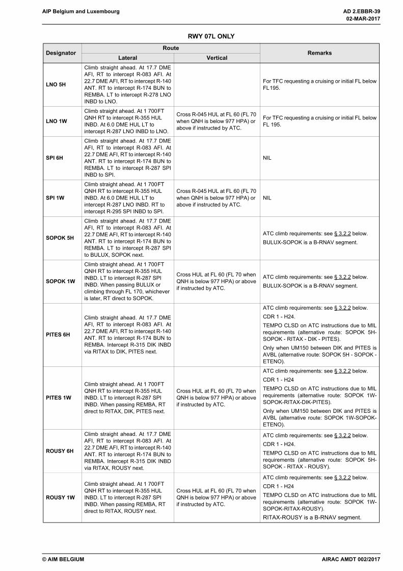
AIP Belgium and Luxembourg AD 2.EBBR-39
© AIM BELGIUM
RWY 07L ONLY
DesignatorRoute
RemarksLateral Vertical
LNO 5H
Climb straight ahead. At 17.7 DMEAFI, RT to intercept R-083 AFI. At22.7 DME AFI, RT to intercept R-140ANT. RT to intercept R-174 BUN toREMBA. LT to intercept R-278 LNOINBD to LNO.
For TFC requesting a cruising or initial FL belowFL195.
LNO 1W
Climb straight ahead. At 1 700FT QNH RT to intercept R-355 HUL INBD. At 6.0 DME HUL LT to intercept R-287 LNO INBD to LNO.
Cross R-045 HUL at FL 60 (FL 70 when QNH is below 977 HPA) or above if instructed by ATC.
For TFC requesting a cruising or initial FL belowFL 195.
SPI 6H
Climb straight ahead. At 17.7 DMEAFI, RT to intercept R-083 AFI. At22.7 DME AFI, RT to intercept R-140ANT. RT to intercept R-174 BUN toREMBA. LT to intercept R-287 SPIINBD to SPI.
NIL
SPI 1W
Climb straight ahead. At 1 700FT QNH RT to intercept R-355 HUL INBD. At 6.0 DME HUL LT to intercept R-287 LNO INBD. RT to intercept R-295 SPI INBD to SPI.
Cross R-045 HUL at FL 60 (FL 70 when QNH is below 977 HPA) or above if instructed by ATC.
NIL
SOPOK 5H
Climb straight ahead. At 17.7 DMEAFI, RT to intercept R-083 AFI. At22.7 DME AFI, RT to intercept R-140ANT. RT to intercept R-174 BUN toREMBA. LT to intercept R-287 SPIto BULUX, SOPOK next.
ATC climb requirements: see § 3.2.2 below.BULUX-SOPOK is a B-RNAV segment.
SOPOK 1W
Climb straight ahead. At 1 700FT QNH RT to intercept R-355 HUL INBD. LT to intercept R-287 SPI INBD. When passing BULUX or climbing through FL 170, whichever is later, RT direct to SOPOK.
Cross HUL at FL 60 (FL 70 when QNH is below 977 HPA) or above if instructed by ATC.
ATC climb requirements: see § 3.2.2 below.BULUX-SOPOK is a B-RNAV segment.
PITES 6H
Climb straight ahead. At 17.7 DMEAFI, RT to intercept R-083 AFI. At22.7 DME AFI, RT to intercept R-140ANT. RT to intercept R-174 BUN toREMBA. Intercept R-315 DIK INBDvia RITAX to DIK, PITES next.
ATC climb requirements: see § 3.2.2 below.CDR 1 - H24.TEMPO CLSD on ATC instructions due to MILrequirements (alternative route: SOPOK 5H-SOPOK - RITAX - DIK - PITES).Only when UM150 between DIK and PITES isAVBL (alternative route: SOPOK 5H - SOPOK -ETENO).
PITES 1W
Climb straight ahead. At 1 700FT QNH RT to intercept R-355 HUL INBD. LT to intercept R-287 SPI INBD. When passing REMBA, RT direct to RITAX, DIK, PITES next.
Cross HUL at FL 60 (FL 70 when QNH is below 977 HPA) or above if instructed by ATC.
ATC climb requirements: see § 3.2.2 below.CDR 1 - H24TEMPO CLSD on ATC instructions due to MILrequirements (alternative route: SOPOK 1W-SOPOK-RITAX-DIK-PITES).Only when UM150 between DIK and PITES isAVBL (alternative route: SOPOK 1W-SOPOK-ETENO).
ROUSY 6H
Climb straight ahead. At 17.7 DMEAFI, RT to intercept R-083 AFI. At22.7 DME AFI, RT to intercept R-140ANT. RT to intercept R-174 BUN toREMBA. Intercept R-315 DIK INBDvia RITAX, ROUSY next.
ATC climb requirements: see § 3.2.2 below.CDR 1 - H24.TEMPO CLSD on ATC instructions due to MILrequirements (alternative route: SOPOK 5H-SOPOK - RITAX - ROUSY).
ROUSY 1W
Climb straight ahead. At 1 700FT QNH RT to intercept R-355 HUL INBD. LT to intercept R-287 SPI INBD. When passing REMBA, RT direct to RITAX, ROUSY next.
Cross HUL at FL 60 (FL 70 when QNH is below 977 HPA) or above if instructed by ATC.
ATC climb requirements: see § 3.2.2 below.CDR 1 - H24TEMPO CLSD on ATC instructions due to MILrequirements (alternative route: SOPOK 1W-SOPOK-RITAX-ROUSY).RITAX-ROUSY is a B-RNAV segment.
AIRAC AMDT 002/2017
02-MAR-2017
02-MAR-2017
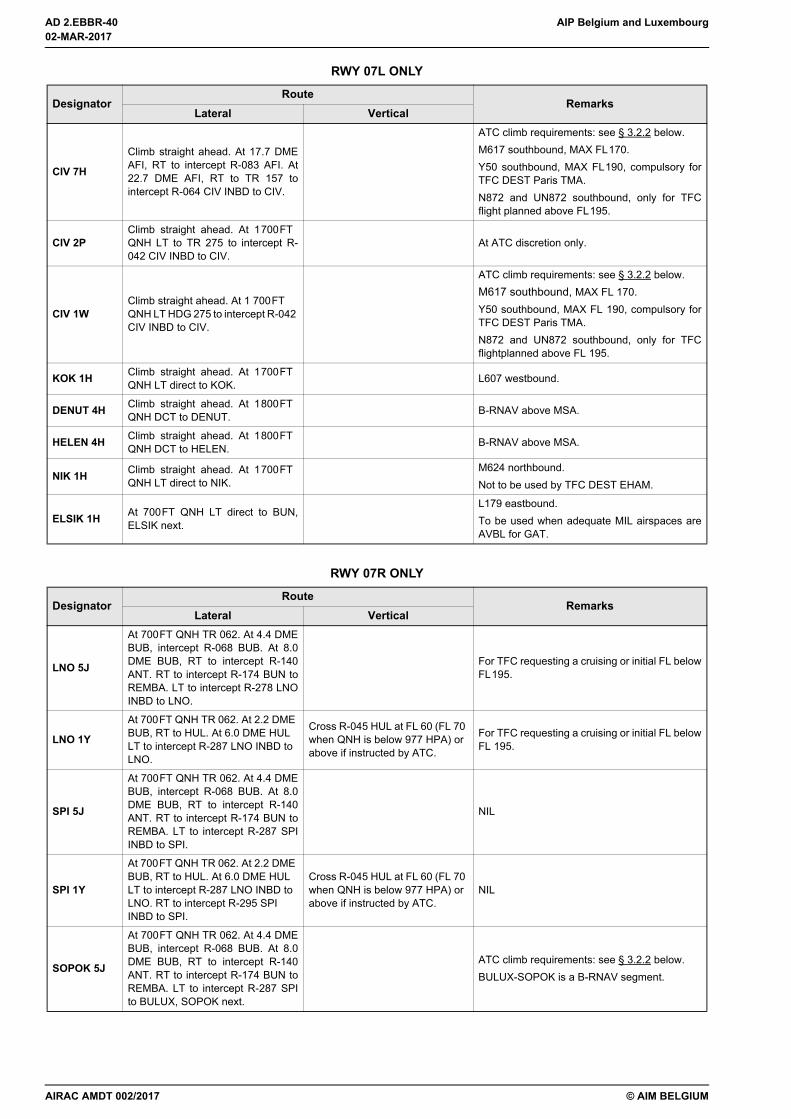
AD 2.EBBR-40 AIP Belgium and Luxembourg
© AIM BELGIUM
CIV 7H
Climb straight ahead. At 17.7 DMEAFI, RT to intercept R-083 AFI. At22.7 DME AFI, RT to TR 157 tointercept R-064 CIV INBD to CIV.
ATC climb requirements: see § 3.2.2 below.M617 southbound, MAX FL170.Y50 southbound, MAX FL190, compulsory forTFC DEST Paris TMA.N872 and UN872 southbound, only for TFCflight planned above FL195.
CIV 2PClimb straight ahead. At 1700FT QNH LT to TR 275 to intercept R-042 CIV INBD to CIV.
At ATC discretion only.
CIV 1WClimb straight ahead. At 1 700FT QNH LT HDG 275 to intercept R-042 CIV INBD to CIV.
ATC climb requirements: see § 3.2.2 below.M617 southbound, MAX FL 170.Y50 southbound, MAX FL 190, compulsory forTFC DEST Paris TMA.N872 and UN872 southbound, only for TFCflightplanned above FL 195.
KOK 1H Climb straight ahead. At 1700FT QNH LT direct to KOK. L607 westbound.
DENUT 4H Climb straight ahead. At 1800FT QNH DCT to DENUT. B-RNAV above MSA.
HELEN 4H Climb straight ahead. At 1800FT QNH DCT to HELEN. B-RNAV above MSA.
NIK 1H Climb straight ahead. At 1700FT QNH LT direct to NIK.
M624 northbound.Not to be used by TFC DEST EHAM.
ELSIK 1H At 700FT QNH LT direct to BUN,ELSIK next.
L179 eastbound.To be used when adequate MIL airspaces areAVBL for GAT.
RWY 07R ONLY
DesignatorRoute
RemarksLateral Vertical
LNO 5J
At 700FT QNH TR 062. At 4.4 DMEBUB, intercept R-068 BUB. At 8.0DME BUB, RT to intercept R-140ANT. RT to intercept R-174 BUN toREMBA. LT to intercept R-278 LNOINBD to LNO.
For TFC requesting a cruising or initial FL belowFL195.
LNO 1Y
At 700FT QNH TR 062. At 2.2 DME BUB, RT to HUL. At 6.0 DME HUL LT to intercept R-287 LNO INBD to LNO.
Cross R-045 HUL at FL 60 (FL 70 when QNH is below 977 HPA) or above if instructed by ATC.
For TFC requesting a cruising or initial FL belowFL 195.
SPI 5J
At 700FT QNH TR 062. At 4.4 DMEBUB, intercept R-068 BUB. At 8.0DME BUB, RT to intercept R-140ANT. RT to intercept R-174 BUN toREMBA. LT to intercept R-287 SPIINBD to SPI.
NIL
SPI 1Y
At 700FT QNH TR 062. At 2.2 DME BUB, RT to HUL. At 6.0 DME HUL LT to intercept R-287 LNO INBD to LNO. RT to intercept R-295 SPI INBD to SPI.
Cross R-045 HUL at FL 60 (FL 70 when QNH is below 977 HPA) or above if instructed by ATC.
NIL
SOPOK 5J
At 700FT QNH TR 062. At 4.4 DMEBUB, intercept R-068 BUB. At 8.0DME BUB, RT to intercept R-140ANT. RT to intercept R-174 BUN toREMBA. LT to intercept R-287 SPIto BULUX, SOPOK next.
ATC climb requirements: see § 3.2.2 below.BULUX-SOPOK is a B-RNAV segment.
RWY 07L ONLY
DesignatorRoute
RemarksLateral Vertical
02-MAR-2017
02-MAR-2017
AIRAC AMDT 002/2017
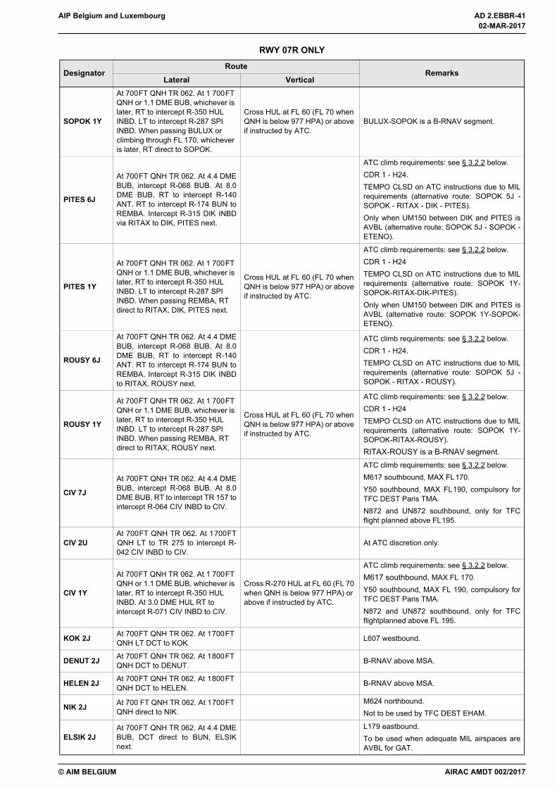
AIP Belgium and Luxembourg AD 2.EBBR-41
© AIM BELGIUM
SOPOK 1Y
At 700FT QNH TR 062. At 1 700FT QNH or 1.1 DME BUB, whichever is later, RT to intercept R-350 HUL INBD. LT to intercept R-287 SPI INBD. When passing BULUX or climbing through FL 170, whichever is later, RT direct to SOPOK.
Cross HUL at FL 60 (FL 70 when QNH is below 977 HPA) or above if instructed by ATC.
BULUX-SOPOK is a B-RNAV segment.
PITES 6J
At 700FT QNH TR 062. At 4.4 DMEBUB, intercept R-068 BUB. At 8.0DME BUB, RT to intercept R-140ANT. RT to intercept R-174 BUN toREMBA. Intercept R-315 DIK INBDvia RITAX to DIK, PITES next.
ATC climb requirements: see § 3.2.2 below.CDR 1 - H24.TEMPO CLSD on ATC instructions due to MILrequirements (alternative route: SOPOK 5J -SOPOK - RITAX - DIK - PITES).Only when UM150 between DIK and PITES isAVBL (alternative route: SOPOK 5J - SOPOK -ETENO).
PITES 1Y
At 700FT QNH TR 062. At 1 700FT QNH or 1.1 DME BUB, whichever is later, RT to intercept R-350 HUL INBD. LT to intercept R-287 SPI INBD. When passing REMBA, RT direct to RITAX, DIK, PITES next.
Cross HUL at FL 60 (FL 70 when QNH is below 977 HPA) or above if instructed by ATC.
ATC climb requirements: see § 3.2.2 below.CDR 1 - H24TEMPO CLSD on ATC instructions due to MILrequirements (alternative route: SOPOK 1Y-SOPOK-RITAX-DIK-PITES).Only when UM150 between DIK and PITES isAVBL (alternative route: SOPOK 1Y-SOPOK-ETENO).
ROUSY 6J
At 700FT QNH TR 062. At 4.4 DMEBUB, intercept R-068 BUB. At 8.0DME BUB, RT to intercept R-140ANT. RT to intercept R-174 BUN toREMBA. Intercept R-315 DIK INBDto RITAX, ROUSY next.
ATC climb requirements: see § 3.2.2 below.CDR 1 - H24.TEMPO CLSD on ATC instructions due to MILrequirements (alternative route: SOPOK 5J -SOPOK - RITAX - ROUSY).
ROUSY 1Y
At 700FT QNH TR 062. At 1 700FT QNH or 1.1 DME BUB, whichever is later, RT to intercept R-350 HUL INBD. LT to intercept R-287 SPI INBD. When passing REMBA, RT direct to RITAX, ROUSY next.
Cross HUL at FL 60 (FL 70 when QNH is below 977 HPA) or above if instructed by ATC.
ATC climb requirements: see § 3.2.2 below.CDR 1 - H24TEMPO CLSD on ATC instructions due to MILrequirements (alternative route: SOPOK 1Y-SOPOK-RITAX-ROUSY).RITAX-ROUSY is a B-RNAV segment.
CIV 7J
At 700FT QNH TR 062. At 4.4 DMEBUB, intercept R-068 BUB. At 8.0DME BUB, RT to intercept TR 157 tointercept R-064 CIV INBD to CIV.
ATC climb requirements: see § 3.2.2 below.M617 southbound, MAX FL170.Y50 southbound, MAX FL190, compulsory forTFC DEST Paris TMA.N872 and UN872 southbound, only for TFCflight planned above FL195.
CIV 2UAt 700FT QNH TR 062. At 1700FTQNH LT to TR 275 to intercept R-042 CIV INBD to CIV.
At ATC discretion only.
CIV 1Y
At 700FT QNH TR 062. At 1 700FT QNH or 1.1 DME BUB, whichever is later, RT to intercept R-350 HUL INBD. At 3.0 DME HUL RT to intercept R-071 CIV INBD to CIV.
Cross R-270 HUL at FL 60 (FL 70 when QNH is below 977 HPA) or above if instructed by ATC.
ATC climb requirements: see § 3.2.2 below.M617 southbound, MAX FL 170.Y50 southbound, MAX FL 190, compulsory forTFC DEST Paris TMA.N872 and UN872 southbound, only for TFCflightplanned above FL 195.
KOK 2J At 700FT QNH TR 062. At 1700FT QNH LT DCT to KOK. L607 westbound.
DENUT 2J At 700FT QNH TR 062. At 1800FT QNH DCT to DENUT. B-RNAV above MSA.
HELEN 2J At 700FT QNH TR 062. At 1800FT QNH DCT to HELEN. B-RNAV above MSA.
NIK 2J At 700 FT QNH TR 062. At 1700FT QNH direct to NIK.
M624 northbound.Not to be used by TFC DEST EHAM.
ELSIK 2JAt 700FT QNH TR 062. At 4.4 DMEBUB, DCT direct to BUN, ELSIKnext.
L179 eastbound.To be used when adequate MIL airspaces areAVBL for GAT.
RWY 07R ONLY
DesignatorRoute
RemarksLateral Vertical
AIRAC AMDT 002/2017
02-MAR-2017
02-MAR-2017
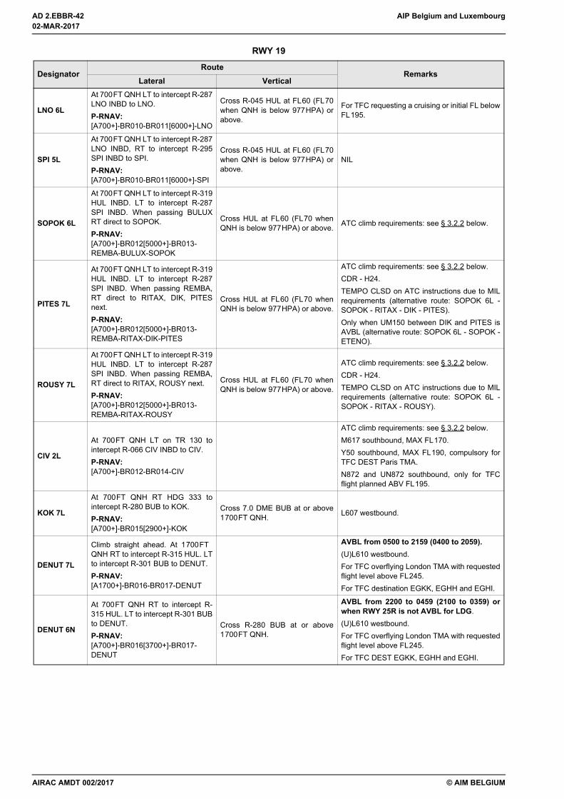
AD 2.EBBR-42 AIP Belgium and Luxembourg
© AIM BELGIUM
RWY 19
DesignatorRoute
RemarksLateral Vertical
LNO 6L
At 700FT QNH LT to intercept R-287LNO INBD to LNO.P-RNAV:[A700+]-BR010-BR011[6000+]-LNO
Cross R-045 HUL at FL60 (FL70when QNH is below 977HPA) orabove.
For TFC requesting a cruising or initial FL belowFL195.
SPI 5L
At 700FT QNH LT to intercept R-287LNO INBD, RT to intercept R-295SPI INBD to SPI.P-RNAV:[A700+]-BR010-BR011[6000+]-SPI
Cross R-045 HUL at FL60 (FL70when QNH is below 977HPA) orabove.
NIL
SOPOK 6L
At 700FT QNH LT to intercept R-319HUL INBD. LT to intercept R-287SPI INBD. When passing BULUXRT direct to SOPOK.P-RNAV:[A700+]-BR012[5000+]-BR013-REMBA-BULUX-SOPOK
Cross HUL at FL60 (FL70 whenQNH is below 977HPA) or above. ATC climb requirements: see § 3.2.2 below.
PITES 7L
At 700FT QNH LT to intercept R-319HUL INBD. LT to intercept R-287SPI INBD. When passing REMBA,RT direct to RITAX, DIK, PITESnext.P-RNAV:[A700+]-BR012[5000+]-BR013-REMBA-RITAX-DIK-PITES
Cross HUL at FL60 (FL70 whenQNH is below 977HPA) or above.
ATC climb requirements: see § 3.2.2 below.CDR - H24.TEMPO CLSD on ATC instructions due to MILrequirements (alternative route: SOPOK 6L -SOPOK - RITAX - DIK - PITES).Only when UM150 between DIK and PITES isAVBL (alternative route: SOPOK 6L - SOPOK -ETENO).
ROUSY 7L
At 700FT QNH LT to intercept R-319HUL INBD. LT to intercept R-287SPI INBD. When passing REMBA,RT direct to RITAX, ROUSY next.P-RNAV:[A700+]-BR012[5000+]-BR013-REMBA-RITAX-ROUSY
Cross HUL at FL60 (FL70 whenQNH is below 977HPA) or above.
ATC climb requirements: see § 3.2.2 below.CDR - H24.TEMPO CLSD on ATC instructions due to MILrequirements (alternative route: SOPOK 6L -SOPOK - RITAX - ROUSY).
CIV 2L
At 700FT QNH LT on TR 130 tointercept R-066 CIV INBD to CIV.P-RNAV:[A700+]-BR012-BR014-CIV
ATC climb requirements: see § 3.2.2 below.M617 southbound, MAX FL170.Y50 southbound, MAX FL190, compulsory forTFC DEST Paris TMA.N872 and UN872 southbound, only for TFCflight planned ABV FL195.
KOK 7L
At 700FT QNH RT HDG 333 tointercept R-280 BUB to KOK.P-RNAV:[A700+]-BR015[2900+]-KOK
Cross 7.0 DME BUB at or above1700FT QNH. L607 westbound.
DENUT 7L
Climb straight ahead. At 1700FT QNH RT to intercept R-315 HUL. LTto intercept R-301 BUB to DENUT.P-RNAV:[A1700+]-BR016-BR017-DENUT
AVBL from 0500 to 2159 (0400 to 2059).(U)L610 westbound.For TFC overflying London TMA with requestedflight level above FL245.For TFC destination EGKK, EGHH and EGHI.
DENUT 6N
At 700FT QNH RT to intercept R-315 HUL. LT to intercept R-301 BUBto DENUT.P-RNAV:[A700+]-BR016[3700+]-BR017-DENUT
Cross R-280 BUB at or above1700FT QNH.
AVBL from 2200 to 0459 (2100 to 0359) orwhen RWY 25R is not AVBL for LDG.(U)L610 westbound.For TFC overflying London TMA with requestedflight level above FL245.For TFC DEST EGKK, EGHH and EGHI.
02-MAR-2017
02-MAR-2017
AIRAC AMDT 002/2017
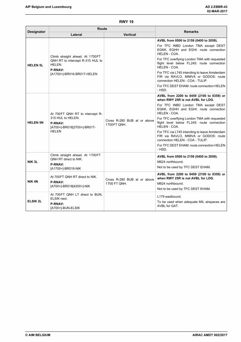
AIP Belgium and Luxembourg AD 2.EBBR-43
© AIM BELGIUM
HELEN 5L
Climb straight ahead. At 1700FT QNH RT to intercept R-315 HUL toHELEN.P-RNAV:[A1700+]-BR016-BR017-HELEN
AVBL from 0500 to 2159 (0400 to 2059).For TFC INBD London TMA except DESTEGKK, EGHH and EGHI: route connectionHELEN - COA.For TFC overflying London TMA with requestedflight level below FL245: route connectionHELEN - COA.For TFC via L745 intending to leave AmsterdamFIR via RAVLO, MIMVA or GODOS: routeconnection HELEN - COA - TULIP.For TFC DEST EHAM: route connection HELEN- HSD.
HELEN 5N
At 700FT QNH RT to intercept R-315 HUL to HELEN.P-RNAV:[A700+]-BR016[3700+]-BR017-HELEN
Cross R-280 BUB at or above1700FT QNH.
AVBL from 2200 to 0459 (2100 to 0359) orwhen RWY 25R is not AVBL for LDG.For TFC INBD London TMA except DESTEGKK, EGHH and EGHI: route connectionHELEN - COA.For TFC overflying London TMA with requestedflight level below FL245: route connectionHELEN - COA.For TFC via L745 intending to leave AmsterdamFIR via RAVLO, MIMVA or GODOS: routeconnection HELEN - COA - TULIP.For TFC DEST EHAM: route connection HELEN- HSD.
NIK 3L
Climb straight ahead. At 1700FT QNH RT direct to NIK.P-RNAV:[A1700+]-BR018-NIK
AVBL from 0500 to 2159 (0400 to 2059).M624 northbound.Not to be used by TFC DEST EHAM.
NIK 4NAt 700FT QNH RT direct to NIK.P-RNAV:[A700+]-BR018[4200+]-NIK
Cross R-280 BUB at or above1700 FT QNH.
AVBL from 2200 to 0459 (2100 to 0359) orwhen RWY 25R is not AVBL for LDG.M624 northbound.Not to be used by TFC DEST EHAM.
ELSIK 2L
At 700FT QNH LT direct to BUN,ELSIK next.P-RNAV:[A700+]-BUN-ELSIK
L179 eastbound.To be used when adequate MIL airspaces areAVBL for GAT.
RWY 19
DesignatorRoute
RemarksLateral Vertical
AIRAC AMDT 002/2017
02-MAR-2017
02-MAR-2017

AD 2.EBBR-44 AIP Belgium and Luxembourg
© AIM BELGIUM
RWY 25L / R
DesignatorRoute
RemarksLateral Vertical
LNO 3D
Climb straight ahead. At 4000FT QNH or when crossing 8.0 DMEBUB, whichever is later, LT to HUL.At HUL intercept R-283 LNO INBDto LNO.
Cross HUL at FL60 (FL70 whenQNH is below 977HPA) or above.
Only AVBL from 0500 to 2159 (0400 to 2059)for DEP RWY 25R and H24 for DEP RWY 25L.For TFC requesting a cruising or initial FL belowFL195.To be used by four-engine aircraft.
SPI 3D
Climb straight ahead. At 4000FT QNH or when crossing 8.0 DMEBUB, whichever is later, LT tointercept R-287 SPI INBD to SPI.
Cross R-225 HUL at FL60 (FL70when QNH is below 977HPA) orabove.
Only AVBL from 0500 to 2159 (0400 to 2059)for DEP RWY 25R and H24 for DEP RWY 25L.To be used by four-engine aircraft.
SOPOK 4D
Climb straight ahead. At 4000FT QNH or when crossing 8.0 DMEBUB whichever is later, LT tointercept R-287 SPI. When passingBULUX or climbing through FL170,whichever is later, RT direct toSOPOK.
Cross R-225 HUL at FL60 (FL70when QNH is below 977HPA) orabove.
Only AVBL from 0500 to 2159 (0400 to 2059)for DEP RWY 25R and H24 for DEP RWY 25L.To be used by four-engine aircraft.ATC climb requirements: see § 3.2.2 below.
PITES 4D
Climb straight ahead. At 4000FT QNH or when crossing 8.0 DMEBUB, whichever is later, LT tointercept R-287 SPI. When passingREMBA, RT direct to RITAX, DIK,PITES next.
Cross R-225 HUL at FL60 (FL70when QNH is below 977HPA) orabove.
Only AVBL from 0500 to 2159 (0400 to 2059)for DEP RWY 25R and H24 for DEP RWY 25L.To be used by four-engine aircraft.ATC climb requirements: see § 3.2.2 below.CDR 1 - H24.TEMPO CLSD on ATC instructions due to MILrequirements (alternative route: SOPOK 4D -SOPOK - RITAX - DIK - PITES).Only when UM150 between DIK and PITES isAVBL (alternative route: SOPOK 4D - SOPOK -ETENO).
ROUSY 4D
Climb straight ahead. At 4000FT QNH or when crossing 8.0 DMEBUB, whichever is later, LT tointercept R-287 SPI. When passingREMBA, RT direct to RITAX,ROUSY next.
Cross R-225 HUL at FL60 (FL70when QNH is below 977HPA) orabove.
Only AVBL from 0500 to 2159 (0400 to 2059)for DEP RWY 25R and H24 for DEP RWY 25L.To be used by four-engine aircraft.ATC climb requirements: see § 3.2.2 below.CDR 1 - H24.TEMPO CLSD on ATC instructions due to MILrequirements (alternative route: SOPOK 4D -SOPOK - RITAX - ROUSY).
CIV 4C
At 700FT QNH RT on track 292° tointercept R-273 BUB. At 6.7 DMEBUB, LT to intercept R-041 CIVINBD to CIV.
Not AVBL during weekends from 0500 to2159 (0400 to 2059).ATC climb requirements: see § 3.2.2 below.M617 southbound, MAX FL170.Y50 southbound, MAX FL190, compulsory forTFC DEST Paris TMA.N872 and UN872 southbound, only for TFCflight planned ABV FL195.
KOK 4C At 700FT QNH RT HDG 290 tointercept R-280 BUB to KOK.
Cross 7.0 DME BUB at or above1700FT QNH. L607 westbound.
DENUT 6CAt 700FT QNH RT on track 297° tointercept R-278 BUB. RT to interceptR-308 HUL to DENUT.
Cross R-280 BUB at or above 1700FT QNH.
(U)L610 westbound.For TFC overflying London TMA with requestedflight level above FL245.For TFC DEST EGKK, EGHH and EGHI.
HELEN 6C At 700FT QNH RT on track 305° tointercept R-315 HUL to HELEN.
Cross R-280 BUB at or above1700FT QNH.
For TFC INBD London TMA except DESTEGKK, EGHH and EGHI: route connectionHELEN - COA.For TFC overflying London TMA with requestedflight level below FL245: route connectionHELEN - COA.For TFC via L745 intending to leave AmsterdamFIR via RAVLO, MIMVA or GODOS: routeconnection HELEN - COA - TULIP.For TFC DEST EHAM: route connection HELEN- HSD.
02-MAR-2017
02-MAR-2017
AIRAC AMDT 002/2017
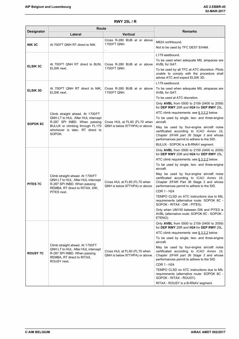
AIP Belgium and Luxembourg AD 2.EBBR-45
© AIM BELGIUM
NIK 3C At 700FT QNH RT direct to NIK.Cross R-280 BUB at or above1700FT QNH..
M624 northbound.Not to be used by TFC DEST EHAM.
ELSIK 3C At 700FT QNH RT direct to BUN,ELSIK next.
Cross R-280 BUB at or above1700FT QNH.
L179 eastbound.To be used when adequate MIL airspaces areAVBL for GAT.To be used by all TFC at ATC discretion. Pilotsunable to comply with the procedure shalladvise ATC and expect ELSIK 3D.
ELSIK 3D At 700FT QNH RT direct to NIK,ELSIK next.
Cross R-280 BUB at or above1700FT QNH.
L179 eastbound.To be used when adequate MIL airspaces areAVBL for GAT.To be used at ATC discretion.
SOPOK 8C
Climb straight ahead. At 1700FT QNH LT to HUL. After HUL interceptR-287 SPI INBD. When passingBULUX or climbing through FL170whichever is later, RT direct toSOPOK.
Cross HUL at FL60 (FL70 whenQNH is below 977HPA) or above.
Only AVBL from 0500 to 2159 (0400 to 2059)for DEP RWY 25R and H24 for DEP RWY 25L.ATC climb requirements: see § 3.2.2 below.To be used by single, two- and three-engineaircraft.May be used by four-engine aircraft noisecertificated according to ICAO Annex 16,Chapter 3/FAR part 36 Stage 3 and whoseperformances permit to adhere to the SID.BULUX - SOPOK is a B-RNAV segment.
PITES 7C
Climb straight ahead. At 1700FT QNH LT to HUL. After HUL intercept R-287 SPI INBD. When passing REMBA, RT direct to RITAX, DIK, PITES next.
Cross HUL at FL60 (FL70 when QNH is below 977HPA) or above.
Only AVBL from 0500 to 2159 (0400 to 2059)for DEP RWY 25R and H24 for DEP RWY 25L.ATC climb requirements: see § 3.2.2 below.To be used by single, two- and three-engineaircraft.May be used by four-engine aircraft noisecertificated according to ICAO Annex 16,Chapter 3/FAR Part 36 Stage 3 and whoseperformances permit to adhere to the SID.CDR 1 - H24TEMPO CLSD on ATC instructions due to MILrequirements (alternative route: SOPOK 8C -SOPOK - RITAX - DIK - PITES).Only when UM150 between DIK and PITES isAVBL (alternative route: SOPOK 8C - SOPOK -ETENO).
ROUSY 7C
Climb straight ahead. At 1700FT QNH LT to HUL. After HUL intercept R-287 SPI INBD. When passing REMBA, RT direct to RITAX, ROUSY next.
Cross HUL at FL60 (FL70 when QNH is below 977HPA) or above.
Only AVBL from 0500 to 2159 (0400 to 2059)for DEP RWY 25R and H24 for DEP RWY 25L.ATC climb requirements: see § 3.2.2 below.To be used by single, two- and three-engineaircraft.May be used by four-engine aircraft noisecertificated according to ICAO Annex 16,Chapter 3/FAR part 36 Stage 3 and whoseperformances permit to adhere to the SID.CDR 1 - H24TEMPO CLSD on ATC instructions due to MILrequirements (alternative route: SOPOK 8C -SOPOK - RITAX - ROUSY).RITAX - ROUSY is a B-RNAV segment.
RWY 25L / R
DesignatorRoute
RemarksLateral Vertical
AIRAC AMDT 002/2017
02-MAR-2017
02-MAR-2017
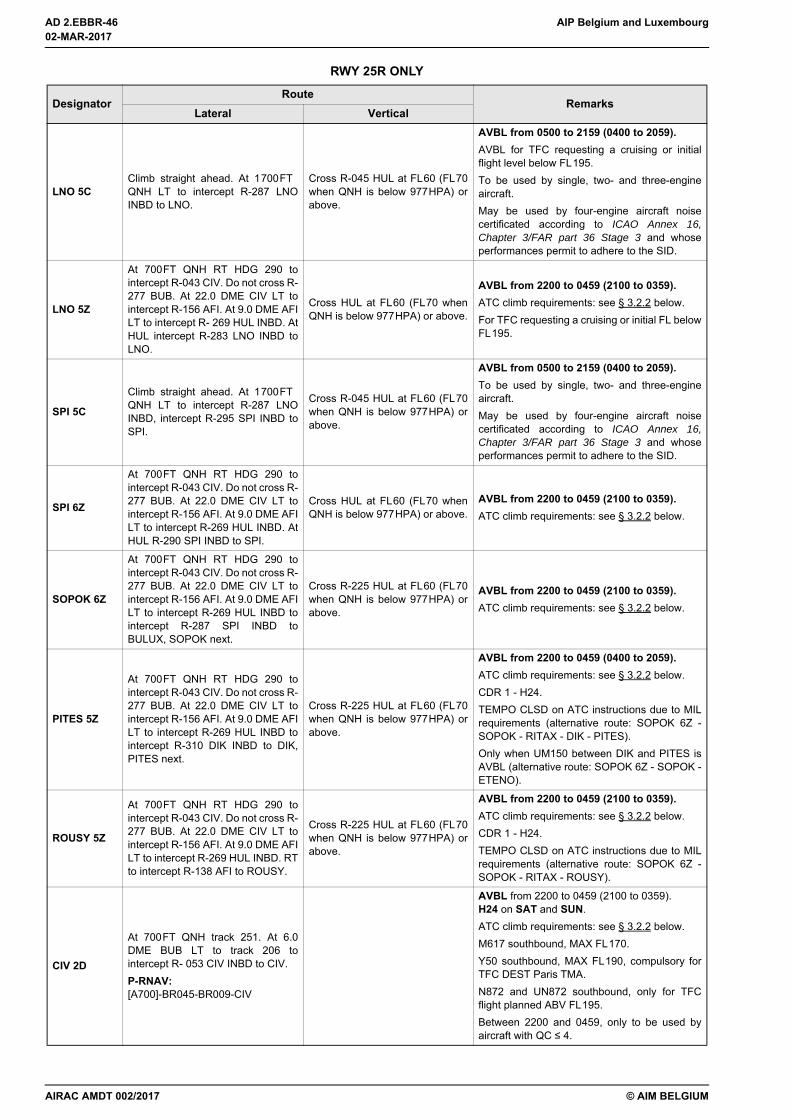
AD 2.EBBR-46 AIP Belgium and Luxembourg
© AIM BELGIUM
RWY 25R ONLY
DesignatorRoute
RemarksLateral Vertical
LNO 5CClimb straight ahead. At 1700FT QNH LT to intercept R-287 LNOINBD to LNO.
Cross R-045 HUL at FL60 (FL70when QNH is below 977HPA) orabove.
AVBL from 0500 to 2159 (0400 to 2059).AVBL for TFC requesting a cruising or initialflight level below FL195.To be used by single, two- and three-engineaircraft.May be used by four-engine aircraft noisecertificated according to ICAO Annex 16,Chapter 3/FAR part 36 Stage 3 and whoseperformances permit to adhere to the SID.
LNO 5Z
At 700FT QNH RT HDG 290 tointercept R-043 CIV. Do not cross R-277 BUB. At 22.0 DME CIV LT tointercept R-156 AFI. At 9.0 DME AFILT to intercept R- 269 HUL INBD. AtHUL intercept R-283 LNO INBD toLNO.
Cross HUL at FL60 (FL70 whenQNH is below 977HPA) or above.
AVBL from 2200 to 0459 (2100 to 0359).ATC climb requirements: see § 3.2.2 below.For TFC requesting a cruising or initial FL belowFL195.
SPI 5C
Climb straight ahead. At 1700FT QNH LT to intercept R-287 LNOINBD, intercept R-295 SPI INBD toSPI.
Cross R-045 HUL at FL60 (FL70when QNH is below 977HPA) orabove.
AVBL from 0500 to 2159 (0400 to 2059).To be used by single, two- and three-engineaircraft.May be used by four-engine aircraft noisecertificated according to ICAO Annex 16,Chapter 3/FAR part 36 Stage 3 and whoseperformances permit to adhere to the SID.
SPI 6Z
At 700FT QNH RT HDG 290 tointercept R-043 CIV. Do not cross R-277 BUB. At 22.0 DME CIV LT tointercept R-156 AFI. At 9.0 DME AFILT to intercept R-269 HUL INBD. AtHUL R-290 SPI INBD to SPI.
Cross HUL at FL60 (FL70 whenQNH is below 977HPA) or above.
AVBL from 2200 to 0459 (2100 to 0359).ATC climb requirements: see § 3.2.2 below.
SOPOK 6Z
At 700FT QNH RT HDG 290 tointercept R-043 CIV. Do not cross R-277 BUB. At 22.0 DME CIV LT tointercept R-156 AFI. At 9.0 DME AFILT to intercept R-269 HUL INBD tointercept R-287 SPI INBD toBULUX, SOPOK next.
Cross R-225 HUL at FL60 (FL70when QNH is below 977HPA) orabove.
AVBL from 2200 to 0459 (2100 to 0359).ATC climb requirements: see § 3.2.2 below.
PITES 5Z
At 700FT QNH RT HDG 290 tointercept R-043 CIV. Do not cross R-277 BUB. At 22.0 DME CIV LT tointercept R-156 AFI. At 9.0 DME AFILT to intercept R-269 HUL INBD tointercept R-310 DIK INBD to DIK,PITES next.
Cross R-225 HUL at FL60 (FL70when QNH is below 977HPA) orabove.
AVBL from 2200 to 0459 (0400 to 2059).ATC climb requirements: see § 3.2.2 below.CDR 1 - H24.TEMPO CLSD on ATC instructions due to MILrequirements (alternative route: SOPOK 6Z -SOPOK - RITAX - DIK - PITES).Only when UM150 between DIK and PITES isAVBL (alternative route: SOPOK 6Z - SOPOK -ETENO).
ROUSY 5Z
At 700FT QNH RT HDG 290 tointercept R-043 CIV. Do not cross R-277 BUB. At 22.0 DME CIV LT tointercept R-156 AFI. At 9.0 DME AFILT to intercept R-269 HUL INBD. RTto intercept R-138 AFI to ROUSY.
Cross R-225 HUL at FL60 (FL70when QNH is below 977HPA) orabove.
AVBL from 2200 to 0459 (2100 to 0359).ATC climb requirements: see § 3.2.2 below.CDR 1 - H24.TEMPO CLSD on ATC instructions due to MILrequirements (alternative route: SOPOK 6Z -SOPOK - RITAX - ROUSY).
CIV 2D
At 700FT QNH track 251. At 6.0DME BUB LT to track 206 tointercept R- 053 CIV INBD to CIV.P-RNAV:[A700]-BR045-BR009-CIV
AVBL from 2200 to 0459 (2100 to 0359).H24 on SAT and SUN.ATC climb requirements: see § 3.2.2 below.M617 southbound, MAX FL170.Y50 southbound, MAX FL190, compulsory forTFC DEST Paris TMA.N872 and UN872 southbound, only for TFCflight planned ABV FL195.Between 2200 and 0459, only to be used byaircraft with QC ≤ 4.
02-MAR-2017
02-MAR-2017
AIRAC AMDT 002/2017

AIP Belgium and Luxembourg AD 2.EBBR-47
© AIM BELGIUM
3.2.1.2 Waypoint Information
3.2.1.3 Path Terminators
Note: The following database entries are suggestions only and should be checked by a professional database coder before entry into an active database.
RWY 25L ONLY
DesignatorRoute
RemarksLateral Vertical
LNO 5Q At 700FT QNH LT to intercept R-287LNO INBD to LNO.
Cross R-045 HUL at FL60 (FL70when QNH is below 977HPA) orabove.
To be used by single, two- and three-engineaircraft.May be used by four-engine aircraft noisecertificated according to ICAO Annex 16,Chapter 3/FAR part 36 Stage 3 and whoseperformances permit to adhere to the SID.For TFC requesting a cruising or initial FL belowFL195.
SPI 5QAt 700FT QNH LT to intercept R-287LNO INBD, intercept R-295 SPIINBD to SPI.
Cross R-045 HUL at FL60 (FL70when QNH is below 977HPA) orabove.
To be used by single, two- and three-engineaircraft.May be used by four-engine aircraft noisecertificated according to ICAO Annex 16,Chapter 3/FAR Part 36 Stage 3 and whoseperformances permit to adhere to the SID.
CIV 2QClimb straight ahead. At 7.0 DMEBUB LT to TR 206° to intercept R-053 CIV INBD to CIV.
AVBL from 2200 to 0459 (2100 to 0359).H24 on SAT and SUN.ATC climb requirements: see § 3.2.2 below.M617 southbound, MAX FL170.Y50 southbound, MAX FL190, compulsory forTFC DEST Paris TMA.N872 and UN872 southbound, only for TFCflight planned ABV FL195.Between 2200 and 0459, only to be used byaircraft with QC ≤ 4.
ID Latitude LongitudeBR009 504645.6N 0041652.9E
BR010 504759.7N 0043857.8E
BR011 504634.6N 0044604.2E
BR012 504642.1N 0043607.3E
BR013 504200.3N 0044228.9E
BR014 504315.6N 0042300.9E
BR015 505527.1N 0042026.7E
BR016 505707.5N 0041921.6E
BR017 510208.8N 0041122.9E
BR018 505823.7N 0041943.8E
BR045 505247.9N 0042143.7E
RWR25 505441.5N 0042957.7E
AMDT 011/2017
12-OCT-2017
12-OCT-2017
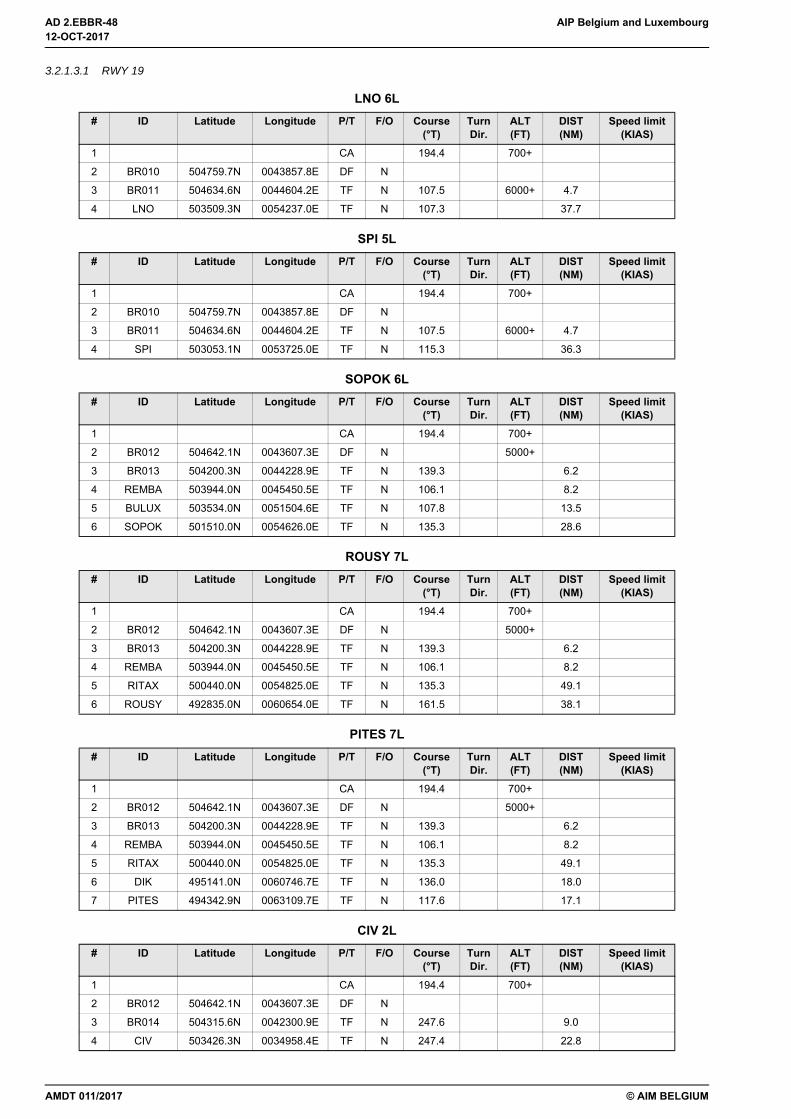
AD 2.EBBR-48 AIP Belgium and Luxembourg
© AIM BELGIUM
3.2.1.3.1 RWY 19
LNO 6L# ID Latitude Longitude P/T F/O Course
(°T)Turn Dir.
ALT (FT)
DIST (NM)
Speed limit (KIAS)
1 CA 194.4 700+
2 BR010 504759.7N 0043857.8E DF N
3 BR011 504634.6N 0044604.2E TF N 107.5 6000+ 4.7
4 LNO 503509.3N 0054237.0E TF N 107.3 37.7
SPI 5L# ID Latitude Longitude P/T F/O Course
(°T)Turn Dir.
ALT (FT)
DIST (NM)
Speed limit (KIAS)
1 CA 194.4 700+
2 BR010 504759.7N 0043857.8E DF N
3 BR011 504634.6N 0044604.2E TF N 107.5 6000+ 4.7
4 SPI 503053.1N 0053725.0E TF N 115.3 36.3
SOPOK 6L# ID Latitude Longitude P/T F/O Course
(°T)Turn Dir.
ALT (FT)
DIST (NM)
Speed limit (KIAS)
1 CA 194.4 700+
2 BR012 504642.1N 0043607.3E DF N 5000+
3 BR013 504200.3N 0044228.9E TF N 139.3 6.2
4 REMBA 503944.0N 0045450.5E TF N 106.1 8.2
5 BULUX 503534.0N 0051504.6E TF N 107.8 13.5
6 SOPOK 501510.0N 0054626.0E TF N 135.3 28.6
ROUSY 7L# ID Latitude Longitude P/T F/O Course
(°T)Turn Dir.
ALT (FT)
DIST (NM)
Speed limit (KIAS)
1 CA 194.4 700+
2 BR012 504642.1N 0043607.3E DF N 5000+
3 BR013 504200.3N 0044228.9E TF N 139.3 6.2
4 REMBA 503944.0N 0045450.5E TF N 106.1 8.2
5 RITAX 500440.0N 0054825.0E TF N 135.3 49.1
6 ROUSY 492835.0N 0060654.0E TF N 161.5 38.1
PITES 7L# ID Latitude Longitude P/T F/O Course
(°T)Turn Dir.
ALT (FT)
DIST (NM)
Speed limit (KIAS)
1 CA 194.4 700+
2 BR012 504642.1N 0043607.3E DF N 5000+
3 BR013 504200.3N 0044228.9E TF N 139.3 6.2
4 REMBA 503944.0N 0045450.5E TF N 106.1 8.2
5 RITAX 500440.0N 0054825.0E TF N 135.3 49.1
6 DIK 495141.0N 0060746.7E TF N 136.0 18.0
7 PITES 494342.9N 0063109.7E TF N 117.6 17.1
CIV 2L# ID Latitude Longitude P/T F/O Course
(°T)Turn Dir.
ALT (FT)
DIST (NM)
Speed limit (KIAS)
1 CA 194.4 700+
2 BR012 504642.1N 0043607.3E DF N
3 BR014 504315.6N 0042300.9E TF N 247.6 9.0
4 CIV 503426.3N 0034958.4E TF N 247.4 22.8
12-OCT-2017
12-OCT-2017
AMDT 011/2017
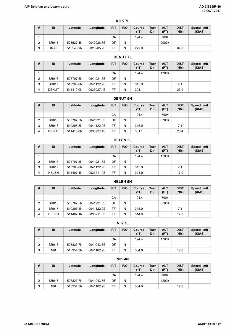
AIP Belgium and Luxembourg AD 2.EBBR-49
© AIM BELGIUM
KOK 7L# ID Latitude Longitude P/T F/O Course
(°T)Turn Dir.
ALT (FT)
DIST (NM)
Speed limit (KIAS)
1 CA 194.4 700+
2 BR015 505527.1N 0042026.7E DF N 2900+
3 KOK 510540.9N 0023905.9E TF N 279.8 64.8
DENUT 7L# ID Latitude Longitude P/T F/O Course
(°T)Turn Dir.
ALT (FT)
DIST (NM)
Speed limit (KIAS)
1 CA 194.4 1700+
2 BR016 505707.5N 0041921.6E DF N
3 BR017 510208.8N 0041122.9E TF N 315.0 7.1
4 DENUT 511410.0N 0033927.4E TF N 301.1 23.4
DENUT 6N# ID Latitude Longitude P/T F/O Course
(°T)Turn Dir.
ALT (FT)
DIST (NM)
Speed limit (KIAS)
1 CA 194.4 700+
2 BR016 505707.5N 0041921.6E DF N 3700+
3 BR017 510208.8N 0041122.9E TF N 315.0 7.1
4 DENUT 511410.0N 0033927.4E TF N 301.1 23.4
HELEN 5L# ID Latitude Longitude P/T F/O Course
(°T)Turn Dir.
ALT (FT)
DIST (NM)
Speed limit (KIAS)
1 CA 194.4 1700+
2 BR016 505707.5N 0041921.6E DF N
3 BR017 510208.8N 0041122.9E TF N 315.0 7.1
4 HELEN 511407.1N 0035211.0E TF N 314.9 17.0
HELEN 5N# ID Latitude Longitude P/T F/O Course
(°T)Turn Dir.
ALT (FT)
DIST (NM)
Speed limit (KIAS)
1 CA 194.4 700+
2 BR016 505707.5N 0041921.6E DF N 3700+
3 BR017 510208.8N 0041122.9E TF N 315.0 7.1
4 HELEN 511407.1N 0035211.0E TF N 314.9 17.0
NIK 3L# ID Latitude Longitude P/T F/O Course
(°T)Turn Dir.
ALT (FT)
DIST (NM)
Speed limit (KIAS)
1 CA 194.4 1700+
2 BR018 505823.7N 0041943.8E DF N
3 NIK 510954.3N 0041102.2E TF N 334.6 12.8
NIK 4N# ID Latitude Longitude P/T F/O Course
(°T)Turn Dir.
ALT (FT)
DIST (NM)
Speed limit (KIAS)
1 CA 194.4 700+
2 BR018 505823.7N 0041943.8E DF N 4200+
3 NIK 510954.3N 0041102.2E TF N 334.6 12.8
AMDT 011/2017
12-OCT-2017
12-OCT-2017
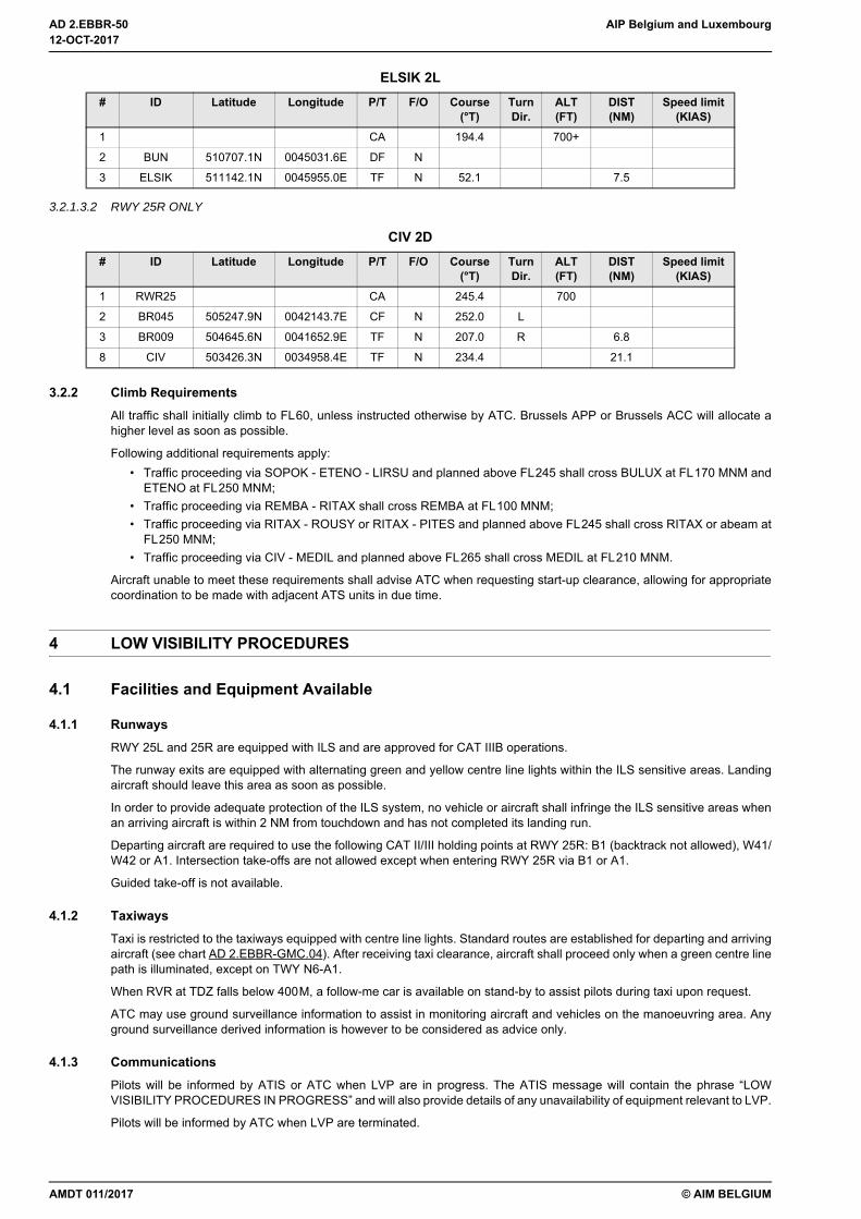
AD 2.EBBR-50 AIP Belgium and Luxembourg
© AIM BELGIUM
3.2.1.3.2 RWY 25R ONLY
3.2.2 Climb RequirementsAll traffic shall initially climb to FL60, unless instructed otherwise by ATC. Brussels APP or Brussels ACC will allocate ahigher level as soon as possible.
Following additional requirements apply:• Traffic proceeding via SOPOK - ETENO - LIRSU and planned above FL245 shall cross BULUX at FL170 MNM and
ETENO at FL250 MNM;• Traffic proceeding via REMBA - RITAX shall cross REMBA at FL100 MNM;• Traffic proceeding via RITAX - ROUSY or RITAX - PITES and planned above FL245 shall cross RITAX or abeam at
FL250 MNM;• Traffic proceeding via CIV - MEDIL and planned above FL265 shall cross MEDIL at FL210 MNM.
Aircraft unable to meet these requirements shall advise ATC when requesting start-up clearance, allowing for appropriatecoordination to be made with adjacent ATS units in due time.
4 LOW VISIBILITY PROCEDURES
4.1 Facilities and Equipment Available
4.1.1 RunwaysRWY 25L and 25R are equipped with ILS and are approved for CAT IIIB operations.
The runway exits are equipped with alternating green and yellow centre line lights within the ILS sensitive areas. Landingaircraft should leave this area as soon as possible.
In order to provide adequate protection of the ILS system, no vehicle or aircraft shall infringe the ILS sensitive areas whenan arriving aircraft is within 2 NM from touchdown and has not completed its landing run.
Departing aircraft are required to use the following CAT II/III holding points at RWY 25R: B1 (backtrack not allowed), W41/W42 or A1. Intersection take-offs are not allowed except when entering RWY 25R via B1 or A1.
Guided take-off is not available.
4.1.2 TaxiwaysTaxi is restricted to the taxiways equipped with centre line lights. Standard routes are established for departing and arrivingaircraft (see chart AD 2.EBBR-GMC.04). After receiving taxi clearance, aircraft shall proceed only when a green centre linepath is illuminated, except on TWY N6-A1.
When RVR at TDZ falls below 400M, a follow-me car is available on stand-by to assist pilots during taxi upon request.
ATC may use ground surveillance information to assist in monitoring aircraft and vehicles on the manoeuvring area. Anyground surveillance derived information is however to be considered as advice only.
4.1.3 CommunicationsPilots will be informed by ATIS or ATC when LVP are in progress. The ATIS message will contain the phrase “LOWVISIBILITY PROCEDURES IN PROGRESS” and will also provide details of any unavailability of equipment relevant to LVP.
Pilots will be informed by ATC when LVP are terminated.
ELSIK 2L# ID Latitude Longitude P/T F/O Course
(°T)Turn Dir.
ALT (FT)
DIST (NM)
Speed limit (KIAS)
1 CA 194.4 700+
2 BUN 510707.1N 0045031.6E DF N
3 ELSIK 511142.1N 0045955.0E TF N 52.1 7.5
CIV 2D# ID Latitude Longitude P/T F/O Course
(°T)Turn Dir.
ALT (FT)
DIST (NM)
Speed limit (KIAS)
1 RWR25 CA 245.4 700
2 BR045 505247.9N 0042143.7E CF N 252.0 L
3 BR009 504645.6N 0041652.9E TF N 207.0 R 6.8
8 CIV 503426.3N 0034958.4E TF N 234.4 21.1
12-OCT-2017
12-OCT-2017
AMDT 011/2017

AIP Belgium and Luxembourg AD 2.EBBR-51
© AIM BELGIUM
4.2 Criteria for Initiation and Termination of LVPThe preparation phase will start when visibility falls below 1500M and/or ceiling is at or below 300FT, and CAT II/IIIoperations are expected. The operations phase will start when RVR falls below 800M or ceiling is below 200FT.
LVP will be terminated when RVR is greater than 800M and ceiling is higher than 200FT, and a continuing improvement inthese conditions is expected.
4.3 Other InformationWhen LVP are in operation, arriving aircraft will be vectored to intercept the ILS at least 10NM from touchdown. ATC willprovide suitable spacing between arrivals to achieve sufficient protection of the ILS sensitive area (see § 4.1.1 above). Thisspacing will be in the order of 8NM in case of CAT II operations and 10NM during CAT III operations.
The traffic manager will determine the applicable traffic acceptance rate according to the circumstances.
CAT II and CAT III approach practice during normal operations is allowed, but pilots should be aware that due to high trafficintensity, protection of the ILS sensitive area cannot be guaranteed and fluctuations in the ILS signal may occur.
5 VFR FLIGHTS
5.1 GeneralPilots flying to/from EBBR or crossing Brussels CTR or TMA shall adhere strictly to all published procedures and ATCinstructions. Non-adherence can cause unacceptable supplementary workload for ATC and may result in delays for theflights concerned. In any case, IFR traffic will have priority over VFR traffic.
VFR traffic (state aircraft and helicopter flights excluded) shall not enter Brussels CTR or TMA during following periods:• from MON to FRI: 0700-0900 (0600-0800), 1200-1300 (1100-1200) and 1600-1900 (1500-1800);• on SAT: 0700-0800 (0600-0700);• on SUN: 1600-1900 (1500-1800).
Local VFR flights at night within the aerodrome traffic circuit are prohibited.
The published routes are compulsory. All routes are allocated at ATC discretion according to the traffic situation. Pilotsunable to comply shall contact ATC immediately to request an alternative route.
To enhance the see-and-avoid concept, VFR flights operating in Brussels CTR or TMA are advised to switch on theirnavigation, landing and anti-collision lights, and they shall keep a sharp look-out for other aircraft.
In order to improve radar detection, pilots flying transponder equipped aircraft shall set code 7000 in mode A/C. Unlessanother code has been previously allocated, Brussels TWR will allocate a code from series 6301-6313.
5.2 Visual Reporting PointsVFR traffic shall only use following reporting points:
Abbreviation Name Associated landmark PositionAM Abeam Mechelen east of Mechelen, lake Nekker 510117N 0043023E
AT Atomium monument 505342N 0042029E
BE Bertem radar station 505226N 0043659E
CA Brucargo cargo terminal 505420N 0042726E
GB Groot-Bijgaarden motorway intersection R0-E40 505231N 0041626E
HO Haasrode intersection motorway E40 and road N25 505041N 0044302E
KH Kampenhout-Sas intersection canal Leuven-Dijle and road N21 505720N 0043537E
LO Waterloo monument 504042N 0042417E
ME Mechelen water tower 510039N 0042749E
NO Nossegem intersection motorway E40 and road N227 505210N 0043038E
PU Peutie pylon military domain 505555N 0042757E
SH South Herent KBC building at intersection of motorway E314 and road N2
505310N 0044039E
TE Ternat castle 505216N 0041014E
WA Wavre radio and television mast 504426N 0043512E
ZB Forêt de Soignes/Zoniënbos motorway intersection R0-E411 504803N 0042754E
AMDT 010/2017
14-SEP-2017
14-SEP-2017

AD 2.EBBR-52 AIP Belgium and Luxembourg
© AIM BELGIUM
5.3 Inbound Traffic
5.3.1 CommunicationsPilots intending to enter Brussels CTR shall contact Brussels TWR on FREQ 120.775MHZ (entry via AT, GB or ME) or118.600MHZ (entry via HO, LO or WA).
Pilots entering Brussels TMA shall contact Brussels Departure (entry between 2000FT AMSL and FL60) or Brussels ACC(entry above FL60).
All VFR flights with destination EBBR shall report their position and obtain an ATC clearance before entering the BrusselsCTA, TMA or CTR. When practicable, the request shall be made at least 5MIN prior to entry.
5.3.2 Routes
Crossing traffic shall follow the routes indicated above and proceed in accordance with ATC instructions.
Crossing traffic with destination EBGB will not be allowed to route directly to EBGB, but will be instructed to vacate BrusselsCTR via the relevant outbound routes indicated below.
Aircraft crossing Brussels CTR east of EBBR may be instructed by ATC to hold over reporting point SH (northbound traffic)or KH (southbound traffic), awaiting clearance to cross the final approach path of RWY 25L/R.
5.4 Outbound Traffic
5.4.1 CommunicationsPilots departing from EBBR shall request start-up clearance from Brussels Delivery. The clearance will be issued dependingon traffic density.
Together with start-up clearance, pilots will receive instructions regarding the transponder setting, the outbound routes tobe expected and the ATS unit(s) to be contacted with the associated frequency.
Departing traffic with destination EBGB will not be allowed to route directly to EBGB, but will be instructed to vacate BrusselsCTR via the relevant outbound routes indicated below.
RWY 25L/R OR RWY 07L/R IN USE
Arrivals from the NorthJoin Brussels CTR via ME and proceed to PU.Traffic shall remain RIGHT of motorway E19 and enter the aerodrome traffic circuit according to ATC instructions.
Arrivals from the SouthJoin Brussels CTR via WA or LO and proceed to ZB, NO next.Traffic shall remain RIGHT of motorways E411/R0, and enter the aerodrome traffic circuit according to ATC instructions.
RWY 01 (ARR) AND 07L/R (DEP) OR RWY 01/19 IN USE
Arrivals from the WestJoin Brussels CTR via TE and proceed to GB, AT and CA next.Traffic shall remain RIGHT of motorway E40 and enter the aerodrome traffic circuit according to ATC instructions.
Arrivals from the EastJoin Brussels CTR via HO and proceed to BE, NO next.Traffic shall remain RIGHT of motorway E40, and enter the aerodrome traffic circuit according to ATC instructions.
14-SEP-2017
14-SEP-2017
AMDT 010/2017

AIP Belgium and Luxembourg AD 2.EBBR-53
© AIM BELGIUM
5.4.2 Routes
6 HELICOPTER FLIGHTS
All helicopters to and from EBBR are subject to PPR. Prior permission must be obtained before the departure of thehelicopter. In flight requests are not allowed. PPR requests shall be addressed to Brussels Airport Company AirsideInspection:
TEL: + 32 (0) 2 753 69 00FAX: + 32 (0) 2 753 69 09Email: [email protected]
Upon requesting permission to land at or take off from EBBR, notwithstanding any other required information, the pilot willclearly indicate:
• the flight rules under which the flight will be performed: IFR or VFR;• the MOPSC;• the time of the day on which the flight will be performed (day or night flight);• the performance class under which the helicopter will be operated.
Restrictions of use applying to the FATO:• The FATO is limited to:
• helicopters able to climb on a 8% slope all engines running;• VFR traffic only;• day operations only (HJ);• performance class 2 (slope category “C”) and performance class 3 (slope category “B”) operations only;• helicopters that have an MOPSC ≤ 19;
• All helicopters shall take off or land on the designated runway in use in the following conditions:• night operations (HN);• operating under IFR;• operating under performance class 1 (slope category “A”);• if the MOPSC > 19.
7 RADIO COMMUNICATION FAILURE
If an aircraft does not succeed in landing within the 30MIN normally allowed for approach and landing, it shall leave BrusselsCTR and TMA on R-289 BUB at 2200FT QNH or below, and land at the first suitable aerodrome where the weatherconditions allow a visual approach and landing.
See also ENR 1.1, § 1.10.5.
EBBR AD 2.23 Additional Information
1 ATIS
ATIS messages serving inbound and outbound traffic are broadcast H24 (see EBBR AD 2.18).
RWY 19 AND 25L/R IN USE
Departures to the NorthAfter take-off, right turn to PU and proceed via AM.Traffic shall remain RIGHT of motorway E19 and leave Brussels CTR according to ATC instructions.
Departures to the SouthAfter take-off, left turn to NO and proceed via ZB to LO or WA.Traffic shall remain RIGHT of motorways R0/E411 and leave Brussels CTR according to ATC instructions.
RWY 01 AND 07L/R IN USE
Departures to the WestAfter take-off, left turn to CA and proceed via AT, GB and TE.Traffic shall remain RIGHT of motorway E40 and leave Brussels CTR according to ATC instructions.
Departures to the EastAfter take-off, right turn to NO or abeam and proceed via BE and HO.Traffic shall remain RIGHT of motorway E40 and leave Brussels CTR according to ATC instructions.
AIRAC AMDT 002/2017
02-MAR-2017
02-MAR-2017
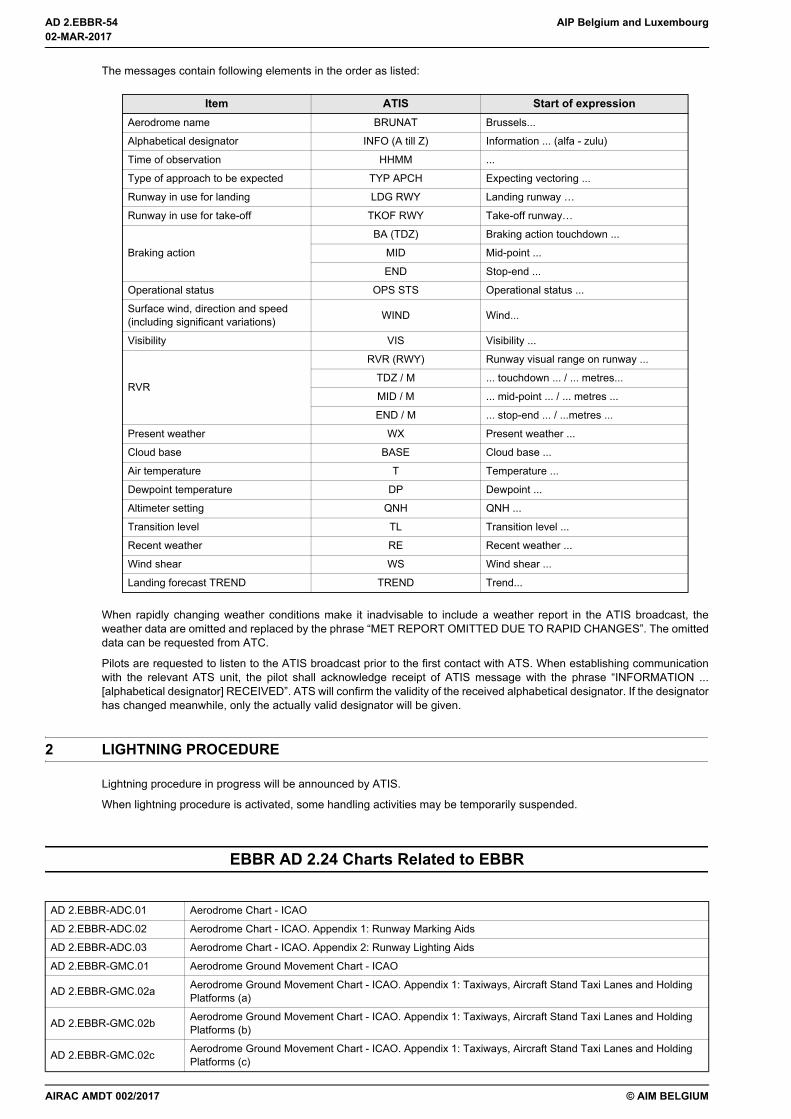
AD 2.EBBR-54 AIP Belgium and Luxembourg
© AIM BELGIUM
The messages contain following elements in the order as listed:
When rapidly changing weather conditions make it inadvisable to include a weather report in the ATIS broadcast, theweather data are omitted and replaced by the phrase “MET REPORT OMITTED DUE TO RAPID CHANGES”. The omitteddata can be requested from ATC.
Pilots are requested to listen to the ATIS broadcast prior to the first contact with ATS. When establishing communicationwith the relevant ATS unit, the pilot shall acknowledge receipt of ATIS message with the phrase “INFORMATION ...[alphabetical designator] RECEIVED”. ATS will confirm the validity of the received alphabetical designator. If the designatorhas changed meanwhile, only the actually valid designator will be given.
2 LIGHTNING PROCEDURE
Lightning procedure in progress will be announced by ATIS.
When lightning procedure is activated, some handling activities may be temporarily suspended.
EBBR AD 2.24 Charts Related to EBBR
Item ATIS Start of expressionAerodrome name BRUNAT Brussels...
Alphabetical designator INFO (A till Z) Information ... (alfa - zulu)
Time of observation HHMM ...
Type of approach to be expected TYP APCH Expecting vectoring ...
Runway in use for landing LDG RWY Landing runway …
Runway in use for take-off TKOF RWY Take-off runway…
Braking action
BA (TDZ) Braking action touchdown ...
MID Mid-point ...
END Stop-end ...
Operational status OPS STS Operational status ...
Surface wind, direction and speed(including significant variations) WIND Wind...
Visibility VIS Visibility ...
RVR
RVR (RWY) Runway visual range on runway ...
TDZ / M ... touchdown ... / ... metres...
MID / M ... mid-point ... / ... metres ...
END / M ... stop-end ... / ...metres ...
Present weather WX Present weather ...
Cloud base BASE Cloud base ...
Air temperature T Temperature ...
Dewpoint temperature DP Dewpoint ...
Altimeter setting QNH QNH ...
Transition level TL Transition level ...
Recent weather RE Recent weather ...
Wind shear WS Wind shear ...
Landing forecast TREND TREND Trend...
AD 2.EBBR-ADC.01 Aerodrome Chart - ICAO
AD 2.EBBR-ADC.02 Aerodrome Chart - ICAO. Appendix 1: Runway Marking Aids
AD 2.EBBR-ADC.03 Aerodrome Chart - ICAO. Appendix 2: Runway Lighting Aids
AD 2.EBBR-GMC.01 Aerodrome Ground Movement Chart - ICAO
AD 2.EBBR-GMC.02a Aerodrome Ground Movement Chart - ICAO. Appendix 1: Taxiways, Aircraft Stand Taxi Lanes and Holding Platforms (a)
AD 2.EBBR-GMC.02b Aerodrome Ground Movement Chart - ICAO. Appendix 1: Taxiways, Aircraft Stand Taxi Lanes and Holding Platforms (b)
AD 2.EBBR-GMC.02c Aerodrome Ground Movement Chart - ICAO. Appendix 1: Taxiways, Aircraft Stand Taxi Lanes and Holding Platforms (c)
02-MAR-2017
02-MAR-2017
AIRAC AMDT 002/2017

AIP Belgium and Luxembourg AD 2.EBBR-55
© AIM BELGIUM
AD 2.EBBR-GMC.02d Aerodrome Ground Movement Chart - ICAO. Appendix 1: Taxiways, Aircraft Stand Taxi Lanes and Holding Platforms (d)
AD 2.EBBR-GMC.03 Aerodrome Ground Movement Chart - ICAO. Appendix 2: Ground Movement Responsibilities
AD 2.EBBR-GMC.04 Aerodrome Ground Movement Chart - ICAO. Appendix 3: Low Visibility Procedures
AD 2.EBBR-GMC.05 Aerodrome Ground Movement Chart - ICAO. Appendix 4: Hot Spots
AD 2.EBBR-GMC.06 Aerodrome Ground Movement Chart - ICAO. Appendix 5: A380 Ground Movements
AD 2.EBBR-APDC.01 Aircraft Parking Docking Chart - ICAO
AD 2.EBBR-APDC.02 Aircraft Parking Docking Chart - ICAO: Apron 9
AD 2.EBBR-APDC.03 Aircraft Parking Docking Chart - ICAO: General Aviation
AD 2.EBBR-AOC.01 Aerodrome Obstacle Chart. Type A (Operating Limitations): RWY 01/19
AD 2.EBBR-AOC.02 Aerodrome Obstacle Chart. Type A (Operating Limitations): RWY 07L/25R
AD 2.EBBR-AOC.03 Aerodrome Obstacle Chart. Type A (Operating Limitations): RWY 07R/25L
AD 2.EBBR-AOC.04 Aerodrome Obstacle Chart. Type B
AD 2.EBBR-PATC.01 Precision Approach Terrain Chart - ICAO: RWY 25L
AD 2.EBBR-PATC.02 Precision Approach Terrain Chart - ICAO: RWY 25R
AD 2.EBBR-ATCSMAC.01 ATC Surveillance Minimum Altitude Chart - ICAO
AD 2.EBBR-STAR.01 Standard Arrival Chart - Instrument - ICAO
AD 2.EBBR-STAR.02 Standard Arrival Chart - Instrument - ICAO (P-RNAV Overlay GNSS / DME-DME)
AD 2.EBBR-SID.01 Standard Departure Chart - Instrument - ICAO: RWY 01
AD 2.EBBR-SID.02 Standard Departure Chart - Instrument - ICAO: RWY 07L
AD 2.EBBR-SID.02a Standard Departure Chart - Instrument - ICAO: RWY 07L
AD 2.EBBR-SID.03 Standard Departure Chart - Instrument - ICAO: RWY 07R
AD 2.EBBR-SID.03a Standard Departure Chart - Instrument - ICAO: RWY 07R
AD 2.EBBR-SID.04a Standard Departure Chart - Instrument - ICAO: RWY 19
AD 2.EBBR-SID.04b Standard Departure Chart - Instrument - ICAO: RWY 19 (P-RNAV Overlay GNSS / DME-DME)
AD 2.EBBR-SID.05a Standard Departure Chart - Instrument - ICAO: RWY 25L (C Departures)
AD 2.EBBR-SID.05b Standard Departure Chart - Instrument - ICAO: RWY 25L (D - Q Departures)
AD 2.EBBR-SID.06a Standard Departure Chart - Instrument - ICAO: RWY 25R (C Departures)
AD 2.EBBR-SID.06b Standard Departure Chart - Instrument - ICAO: RWY 25R (D - Z Departures)
AD 2.EBBR-IAC.01 Instrument Approach Chart - ICAO: ILS or LOC a RWY 25R (IAF ANT/KERKY)
AD 2.EBBR-IAC.02 Instrument Approach Chart - ICAO: ILS or LOC b RWY 25R (IAF FLO)
AD 2.EBBR-IAC.03 Instrument Approach Chart - ICAO: ILS or LOC a RWY 25L (IAF ANT/KERKY)
AD 2.EBBR-IAC.04 Instrument Approach Chart - ICAO: ILS or LOC b RWY 25L (IAF FLO)
AD 2.EBBR-IAC.05 Instrument Approach Chart - ICAO: VOR z RWY 25L (IAF ANT/KERKY)
AD 2.EBBR-IAC.06 Instrument Approach Chart - ICAO: VOR y RWY 25L (IAF FLO)
AD 2.EBBR-IAC.07a Instrument Approach Chart - ICAO: ILS or LOC RWY 01
AD 2.EBBR-IAC.07b Instrument Approach Chart - ICAO: ILS or LOC RWY 01. Appendix: Alternate Routes RWY 01 - On ATC discretion only
AD 2.EBBR-IAC.08 Instrument Approach Chart - ICAO: VOR RWY 07R
AD 2.EBBR-IAC.09 Instrument Approach Chart - ICAO: ILS or LOC RWY 19
AD 2.EBBR-IAC.10 Instrument Approach Chart - ICAO: VOR RWY 07L
AD 2.EBBR-IAC.11 Instrument Approach Chart - ICAO: RNAV (GNSS) RWY 01
AD 2.EBBR-IAC.11a Instrument Approach Chart - ICAO: RNAV (GNSS) RWY 01. Appendix: FAS Datablock
AD 2.EBBR-IAC.12 Instrument Approach Chart - ICAO: RNAV (GNSS) RWY 25L
AD 2.EBBR-IAC.12a Instrument Approach Chart - ICAO: RNAV (GNSS) RWY 25L. Appendix: FAS Datablock
AD 2.EBBR-IAC.13 Instrument Approach Chart - ICAO: RNAV (GNSS) RWY 25R
AD 2.EBBR-IAC.13a Instrument Approach Chart - ICAO: RNAV (GNSS) RWY 25R. Appendix: FAS Datablock
AD 2.EBBR-VAC.01 Visual Approach Chart - ICAO
AMDT 004/2018
29-MAR-2018
29-MAR-2018
AD 2.EBBR-56 AIP Belgium and Luxembourg
© AIM BELGIUM
THIS PAGE INTENTIONALLY LEFT BLANK
29-MAR-2018
29-MAR-2018
AMDT 004/2018
Related Documents