EasyDCC Digital Wireless Throttle System Installation and Setup Guide Quick Start Procedure 1. Install four AAA batteries into throttle. 2. Set desired frequency inside throttle with SW2. Frequency 0 is the default setting from the factory with all switches on. 3. Reinstall throttle in case. 4. Attach antenna - finger tight. 5. Attach antenna to receiver - finger tight. Take care not to strip threads. 6. Set desired mode - scan mode is usual factory setting. 7. Connect receiver to throttle bus or Command Station. 8. Connect 12VAC transformer to receiver. 9. Turn on throttle power switch. 10 Select address and drive away. ©1999 - 2000 By CVP Products All Rights Reserved FCC Information Statement Your wireless throttle is a carefully designed and certified unlicensed low-power transmitter. The FCC ID label and the compliance label serves to show the FCC has authorized this transmitter. This transmitter has been tested and found to comply with the limits for a Class B digital device, pursuant to part 15 of the FCC rules. These limits are designed to provide reasonable protection against harmful interference in a residential installation. This equipment uses and can radiate radio frequency energy and, if not installed and used in accordance with the instructions, may cause harmful interference to radio communications. However, there is no guarantee that interference will not occur in a particular installation. If this equipment does cause harmful interference to radio or television reception, which can be determined by turning the equipment off and on, the user is encouraged to try to correct the interference by one or more of the following measures: - Reorient or relocate the receiving antenna. - Increase the separation between the equipment and the receiver. - Connect the equipment into an outlet on a circuit different from that to which the - Consult the dealer or experienced radio/TV technician for help. receiver is connected. The + end of the battery clips may scratch through a thin or painted-on battery wrapper causing a short circuit to the battery. If you experience this problem with your batteries, use a small strip of tape around the plus end of the battery. Mouser Electronics sells an excellent, low cost “super alkaline” battery, with a sturdy vinyl coating. The Mouser part number is 573-24A and cost about 35 cents in quantities of 100. BATTERY CAUTION BATTERY CAUTION

Welcome message from author
This document is posted to help you gain knowledge. Please leave a comment to let me know what you think about it! Share it to your friends and learn new things together.
Transcript
EasyDCC Digital Wireless Throttle SystemInstallation and Setup Guide
Quick Start Procedure1. Install four AAA batteries into throttle.2. Set desired frequency inside throttle with SW2. Frequency 0 is the default setting from the factory with all switches on.3. Reinstall throttle in case.4. Attach antenna - finger tight.
5. Attach antenna to receiver - finger tight. Take care not to strip threads.6. Set desired mode - scan mode is usual factory setting.7. Connect receiver to throttle bus or Command Station.8. Connect 12VAC transformer to receiver.
9. Turn on throttle power switch.10 Select address and drive away.
©1999 - 2000 By CVP Products All Rights Reserved
FCC Information StatementYour wireless throttle is a carefully designed and certified unlicensed low-power transmitter. The FCC ID label and the compliance label serves to showthe FCC has authorized this transmitter. This transmitter has been tested and found to comply with the limits for a Class B digital device, pursuant to part15 of the FCC rules. These limits are designed to provide reasonable protection against harmful interference in a residential installation. This equipmentuses and can radiate radio frequency energy and, if not installed and used in accordance with the instructions, may cause harmful interference to radiocommunications. However, there is no guarantee that interference will not occur in a particular installation. If this equipment does cause harmfulinterference to radio or television reception, which can be determined by turning the equipment off and on, the user is encouraged to try to correct theinterference by one or more of the following measures:- Reorient or relocate the receiving antenna.- Increase the separation between the equipment and the receiver.
- Connect the equipment into an outlet on a circuit different from that to which the- Consult the dealer or experienced radio/TV technician for help.
receiver is connected.
The + end of the battery clips may scratch through a thin or painted-onbattery wrapper causing a short circuit to the battery. If you experience thisproblem with your batteries, use a small strip of tape around the plus end ofthe battery. Mouser Electronics sells an excellent, low cost “super alkaline”battery, with a sturdy vinyl coating. The Mouser part number is 573-24Aand cost about 35 cents in quantities of 100.
BATTERY CAUTIONBATTERY CAUTION

EasyDCC RX900 Receiver Installation GuidelinesAttaching Receiver Antenna
The threaded aluminum rod serves as the receiver’s antenna. It isshipped unattached for protection. Gently screw in the antennathrough the hole in the top of the case. The antenna should be fingertight for best performance – don’t over tighten.
Receiver Setup Options
There are several options from which to choose. Be sure the throttlemode matches the receiver mode.
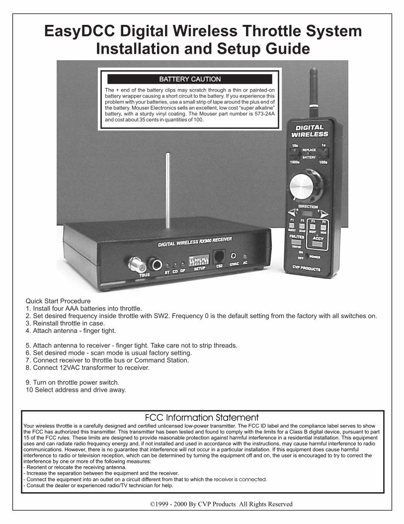
Scan Mode is the most basic setup the most commonly used (A).This mode is recommend when there are no more than 8 throttles inuse and you wish to have each throttle on a dedicated frequency. Thebenefit is fast response time, no time delay, and no interference fromother throttles.
The Burst mode allows multiple throttles to share a single, specificfrequency (B). This mode allows for more than 8 throttles to be usedsimply by adding more receivers. In the burst mode, up to eightthrottles can share a single frequency and the receiver is set to thesame frequency. Since there are 7 unique frequencies, a total of 8x7throttles can be accommodated. In the burst mode, the transmitterturns on for a short moment and “bursts” out the data. It then turnsoff and waits a fixed amount of time before bursting out again.During the quiet time, another throttle can burst out its data.However, since throttles are not synchronized it is possible for twothrottle to burst at the same time. If this occurs, the receiver willignore the both bursts and wait for the next. As more throttles areadded to a frequency you may notice a sluggish response to rapidthrottle speed changes.
Multi-mode provides a convenient way to have the best of both scanand burst mode at the same time (C). Multi-mode allows one receiverto operate in the scan mode, serving up to 6 dedicated throttles. Asecond receiver is set to the burst mode and services another 8throttles. There are two other multi-modes with the only differencebeing the split between dedicated frequencies and shared frequencies.
Receiver Placement
For best reception, mount the receiver at least 5 feet above the floor.Make sure the antenna is not touching nearby objects. Try and placethe receiver in the middle of the room. Walls, pipes, insulation,human bodies and other objects commonly found in the layout roomwill absorb the transmitter’s energy. The fewer obstructions betweenthe receiver and transmitter, the better the reception. No two roomsare alike. Try several locations to determine the best location topermanently mount the receiver.
Hookup Options – Basic Direct
The most basic installation places the receiver near the CommandStation. The CS2 jack on the receiver is connected to theTHROTTLE jack on the Command station using the enclosedmodular cable. Do not use any other type or length of cable. Themodular cable must not be longer than 7 feet.
Hookup Options – Existing Throttle Bus (TBUS)
If you already have tethered throttles in use, you may plug thereceiver into any convenient fascia plate jack using the a Radio Shacktwo conductor coiled guitar cord (RS# 42-978). This is a handy wayto quickly move the receiver about your layout to determine the bestplacement. It does not have to be near the Command Station.
Hookup Options – Using A Dedicated Extender
If you have a large layout requiring more than one receiver or youwish to move the receiver away from the Command Station, youmust add a throttle Extender. Connect the Extender to the CommandStation and use the appropriate length of coaxial cable to connect thereceiver back to the extender.
Throttle Bus Terminator
The end of the EasyDCC throttle bus must be terminated with a 75ohm termination resistor. When your RX900 is at the end of the coax
cable run, you may use the built in terminator. Turn on switch number 7 toactivate the internal termination. Do not use the terminator unless theRX900 is at the end of the coax cable.
Hookup Options – Using A Secondary Receiver
For very large layouts or layouts in unusually poor radio reception areas,an additional receiver may be needed. You must use a special “secondary”receiver for proper operation. You can not simply add another primaryreceiver. The secondary receiver uses special software to allow both theprimary and secondary to receive the same transmission. The tworeceivers then coordinate with each other to decide who places the throttledata on the throttle bus. There are other factors that may influence theusefulness of a secondary receiver. Give us a call to discuss your needs.
Using The RX900 Indicators
The GP LED turns on when good throttle data is received on the properfrequency. This LED is excellent when checking that throttles andreceivers are on the proper frequency. This LED will stay on until the lastthrottle is turned off. This provides a neat way insure all throttles areturned off.
The CD LED briefly turns on whenever throttle data is interrupted. Thismay occur when addresses are changed or throttles are turned off.
The ST LED is on whenever the receiver is recognized by the CommandStation, and valid throttle data is passed on to the Command Station. ThisLED may flicker depending on the number of throttles in use. This isnormal.
Replacement Antennas
The antennas on both units are custom built for CVP. Do not useunauthorized replacements. If your receiver antenna requires replacement,the cost is $1 plus shipping. The handheld throttle’s rubber antennareplacement cost is $7 plus shipping.
Dealing With Interference
Your wireless throttle is a carefully designed unlicensed low-powertransmitter. Unlicensed means other equipment can and do use the samefrequencies as your throttle. The most common source of interference isfrom your own 900MHz cordless telephones (not cellular phones).Cordless 900MHz phones and cordless 900MHz spread-spectrum phonescan jam certain frequencies used by your throttles. Jamming usuallyresults in shorter range and intermittent loss of signal. Here are somesuggestions to deal with interference:
• Try to determine the source of the interference and turn it off.
• Relocate the RX900 receiver or move the jammer away from the
RX900 receiver. This may be as simple as leaving your cordless phoneoutside the layout room.
• Sometimes moving the receiver a 9 inches in one direction or the other
will lessen the interference. Try raising or lowering it also.
• If using scan mode, change to burst mode and try different frequencies.
You will usually find several that work satisfactorily.
• Connect the equipment into an outlet on a circuit different from that towhich the receiver is connected.
• Add a secondary receiver to improve signal reception in distant areas.
EasyDCC Wireless Throttle FrequenciesThe following frequencies are used in the EasyDCC wireless throttle.
F0: 903.37 MHz
F1: 906.37 MHz
F2: 907.87 MHz
F3: 909.37 MHz
F4: 912.37 MHz
F5: 915.37 MHz
F6: 919.87 MHz
F7: 921.37 MHz
8-27-00
FCCID: OKWTX900
ON
1 2 3 4 5 6 7 8
FREQUENCY SELECTION(Burst Mode)
Frequency #0ON
1 2 3 4 5 6 7 8
ON
1 2 3 4 5 6 7 8
ON
1 2 3 4 5 6 7 8
ON
1 2 3 4 5 6 7 8
Frequency #1
Frequency #2
Frequency #3
Frequency #4
ON
1 2 3 4 5 6 7 8
ON
1 2 3 4 5 6 7 8
ON
1 2 3 4 5 6 7 8
ON
1 2 3 4 5 6 7 8
Frequency #5
Frequency #6Fre
qu
en
cy
Sele
ct
1
Fre
qu
en
cy
Sele
ct
2
Fre
qu
en
cy
Sele
ct
3
Mo
de
Sele
ct
MODE SELECT
ON
1 2 3 4 5 6 7 8
ON
1 2 3 4 5 6 7 8
BURST MODE
SCAN MODE
Receives only asingle frequencyset by FS1,FS2, FS3
Receiver scansselected frequenciessee scan table
SETUP SWITCHES
TB
US
So
ckets
CS
2Jack
TB
US
Typ
e
TB
US
Term
inato
r
ENABLE TBUS SOCKETS
CS2 SOCKET
ON
1 2 3 4 5 6 7 8
ON
1 2 3 4 5 6 7 8
CS2 Socket Used
CS2 Socket not used
RX900 uses modularcable between Extenderor Command Station
CS2 socket not used
EasyDCC TBUS in use and RX900E isplugged into either TBUS jack.
If TBUS sockets are not used, bothswitch 5 and 7 must be turned off.
TBUS TERMINATOR
For use when RX900Dis at end of coaxial line
INDICATORS
GP:
CD:
ST:
Good transmission and packets received
Address/frequency dropped
Command Station link OK (status)
AC: 12VAC power present
All frequencies scannednormal setup
FREQUENCY SELECTIONSan and Multimode
All Scan
ON
1 2 3 4 5 6 7 8
ON
1 2 3 4 5 6 7 8
Multimode 1
ON
1 2 3 4 5 6 7 8
Multimode 2
Multimode 3
ON
1 2 3 4 5 6 7 8
Frequency #7
Not available in burstmode - do not use
Frequencies 0-5 scannedFrequency 6,7 ignored
Frequencies 0-4 scannedFrequency 5,6,7 ignored
Frequencies 0-3 scannedFrequency 4,5,6,7 ignored
Terminator OFF
75 ohm terminator ON
F-Jack Screw Connector1/4” headphone jack
IndicatorsSetup switches
6-pin modular jack12VAC transformer input
AC pilot light
Screw-on Antenna
Recommended Setup
ON
1 2 3 4 5 6 7 8
ON
1 2 3 4 5 6 7 8
EasyDCC Model RX900E Wireless Receiver Setup Options
When there are 8 or fewer throttles inuse, the best performance is obtainedwith the receiver and throttles set to
mode. There are only twooptions.SCAN
ON
1 2 3 4 5 6 7 8
This setup is used when theCS2 jack is used. Plug themodular cable into theCommand Station’s “ThrottleJack” or the Extender’s outputjack.
This setup is used when one ofthe TBUS sockets is used.
ON
1 2 3 4 5 6 7 8
Use either coaxial cable or a RadioShack guitar cord to connect theRX900E to the throttle bus (TBUS).
If CS2 jack is used, the modular cablemust not be longer than 7 feet.
FS
1
FS
2
CS
FS
3
E/R
B/S
TM
TB
ON
1 2 3 4 5 6 87
FIG 1 FIG 2
FIG 3
FIG 4
FIG 5 FIG 6
FIG 7 FIG 8
FIG 9
FIG 10
F1
BURST
Frequency #0
ON
1 2 3
ON
1 2 3
ON
1 2 3
Frequency #1
Frequency #2
Frequency #3
Frequency #4
ON
1 2 3
ON
1 2 3
ON
1 2 3
ON
1 2 3
Frequency #5
Frequency #6
ON
1 2 3
Frequency #7
Not available in burstmode - do not use
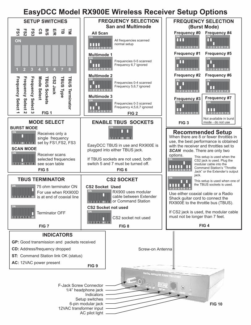
Scan- (Recommended) Burst Mode
F2
SCAN
Note: Throttle is preset tomode at factory.
You may change betweenscan or burst mode at anytime.
SCAN
Push and hold F1 and turn on powerswitch. Yellow (R) LED will turn onsolid indicating Burst Mode isselected. Release F1 and wait forLED to stop flashing. Select throttle’sshared transmit frequency usingSW2 switches. Do not use frequency7 when in burst mode.
THROTTLE MODE SELECTMust Match Receiver Mode
EasyDCC Model TX900E Wireless Throttle Setup And OperationOpening The Throttle
Installing Batteries
Frequency Selection
Antenna Installation
Maximize Battery Life
Battery Life Monitor
Throttle is sent with antenna unattached and face plate held to plastic box witha 4-40 shipping screw. The faceplate holds all the throttles parts and is easilyseparated from the box. First remove the shipping screw and discard. Gentlyremove the face plate from the plastic box by pulling up on the speed knob.Once the battery clips are clear of the box, gently slip the antenna connectorout its hole.
Throttle is designed to use four standard AAA size batteries. Note the polaritysymbol.
Orient the battery with the positive end facing the + symbolon the board. Center the battery in the clips and gently push battery in untillocked in place.
The transmit frequency is selected using the three small switches near theantenna connector. Set the desired transmit frequency with the throttle’s DIPswtiches using the tip of a small (1/8th inch blade) screwdriver tip.
Reassemble faceplate and box. Screw on the antenna until it is finger tightagainst box. Do not over tighten
Throttle does not have an automatic shut off. When throttle is not in use, turn offthe power switch. Alkaline batteries provide the longest lifetime. Battery life isestimated at 25 to 30 hours of continuous use. You may also use rechargeablebatteries. However, they can not be recharged inside the throttle. They must beremoved and recharged with an external battery charger. However,rechargeable batteries will have shorter operation time. When selectingrechargeable batteries, always select AAA size rated at 1.2 to 1.5 volts. Highervoltage batteries will damage throttle.
All batteries face towards bottom off the board. (positive end nearestthe power switch).
When the batteries have about 20 minutes of life remaining, the REPLACEBATTERY indicator will start to flash. You should plan on changing thebatteries soon. Continuing to use weak batteries will result in erratic operation.
Throttle Controls and Operation
Throttle Status Light
Emergency Stop
4-Digit Addressing
Maximizing Transmission Range
Scan Versus Burst Mode
Please refer to your EasyDCC installation and operation manual’s descriptionof the walk-around throttle. The wireless throttle and the tethered throttle haveexactly the same functions and keys. There are a few operating differenceswhich will be described next.
The wireless throttle uses the direction ‘F’ green LED for a status indicator. Ifyou change the locomotive address it begins to flash indicating the throttle hasceased transmission. The throttle will automatically resume transmission inabout 10-15 seconds. This prevents you from accidentally gaining control ofother addresses as you dial through them.
Push and hold the direction key to initiate a system halt. Similar to the tetheredthrottle, both direction indicators will flash. They will continue to flash even if thethrottle power switch is turned off. To restore normal operation, push thedirection key again.
This feature requires the forthcoming upgrade to the Command Stationsoftware, scheduled for mid October 1999. Until the Command Stationsoftware is upgraded, the wireless throttle only supports the standard two digitaddressing mode. Address 00 should not be used. If 00 is selected, none of theindicators will turn on even though the transmitter is on and the battery is beingdrained.
Keep the antenna away from your body and hands. Hold the throttle with theantenna pointed up.
Your throttle is preset to scan mode at the factory. This is the best mode whenno more than 8 throttles are used. Throttles will not interfere with each othersince each throttle has its own unique frequency.
When more than 8 throttles are to be used, use burst mode and multiplefrequencies. In this mode, up to 8 throttles share a single frequency. As the limitof 8 is approached, sluggish response may be noticed. Balanced receiverloading can help. For example, if you plan to use 10 throttles, put 5 throttles onone receiver and 5 on the second receiver.
U2
SW
2
1
ON
2 3
Throttle Frequency SelectionScan and Burst
AntennaConnector
“DIP”Switch SW2
Each throttle in use must be set to afrequency for proper
operation. All 8 frequencies may beused in the scan mode.
differentEach throttle in use must be set to the
frequency for proper operation.Frequency 7 is not available for burstmode and should not be used.
same
One receiver supports up to 8 throttlesin the scan mode.
One receiver supports up to 8 throttlesin the burst mode.
Use additional receivers to increase thetotal number of supported throttles to amaximum of 56.
Maximum number of supportedthrottles is limited to 8 in scan mode.
FIG 11
FIG 12
To change back to Scan mode fromBurst Mode, push and hold F2 andturn on power switch. Green (F) LEDwill turn on solid indicating ScanMode is selected. Release F2 andwait for LED to stop flashing. Selectthrottle’s dedicated transmitfrequency using SW2 switches.
FIG 13
Burst mode allowsthrottles to share a singlefrequency, The frequencyselect switches, figure 11,determine the frequencywhich is shared..
Burst Mode Operation
#1#0 #3#2 #5#4 #7#6
ON
1 2 3 4 5 6 7 8
All Frequencies Scanned
#0
Burst Frequency #0 UsedON
1 2 3 4 5 6 7 8
#0 #0 #0 #0 #0 #0 #0
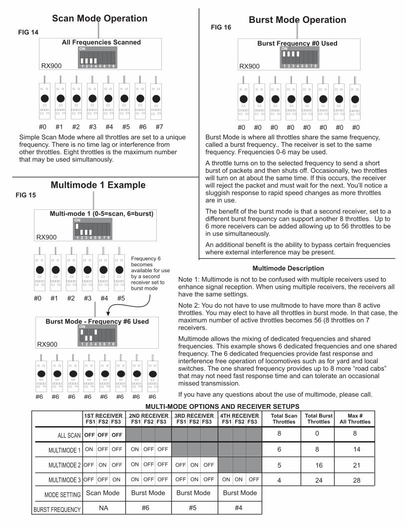
Simple Scan Mode where all throttles are set to a uniquefrequency. There is no time lag or interference fromother throttles. Eight throttles is the maximum numberthat may be used simultanously.
RX900 RX900
Burst Mode is where all throttles share the same frequency,called a burst frequency.. The receiver is set to the samefrequency. Frequencies 0-6 may be used.
A throttle turns on to the selected frequency to send a shortburst of packets and then shuts off. Occasionally, two throttleswill turn on at about the same time. If this occurs, the receiverwill reject the packet and must wait for the next. You’ll notice asluggish response to rapid speed changes as more throttlesare in use.
The benefit of the burst mode is that a second receiver, set to adifferent burst frequency can support another 8 throttles. Up to6 more receivers can be added allowing up to 56 throttles to bein use simultaneously.
An additional benefit is the ability to bypass certain frequencieswhere external interference may be present.
#1#0 #3#2 #5#4
ON
1 2 3 4 5 6 7 8
Multi-mode 1 (0-5=scan, 6=burst)
RX900
#6
Burst Mode - Frequency #6 UsedON
1 2 3 4 5 6 7 8
#6#6 #6 #6 #6 #6 #6
RX900
Frequency 6becomesavailable for useby a secondreceiver set toburst mode
Multimode Description
Note 1: Multimode is not to be confused with multiple receivers used toenhance signal reception. When using multiple receivers, the receivers allhave the same settings.
Note 2: You do not have to use multmode to have more than 8 activethrottles. You may elect to have all throttles in burst mode. In that case, themaximum number of active throttles becomes 56 (8 throttles on 7receivers.
Multimode allows the mixing of dedicated frequencies and sharedfrequencies. This example shows 6 dedicated frequencies and one sharedfrequency. The 6 dedicated frequencies provide fast response andinterference free operation of locomotives such as for yard and localswitches. The one shared frequency provides up to 8 more “road cabs”that may not need fast response time and can tolerate an occasionalmissed transmission.
If you have any questions about the use of multimode, please call.
Scan Mode Operation
Multimode 1 Example
FIG 14
FIG 15
FIG 16
MULTI-MODE OPTIONS AND RECEIVER SETUPS
1ST RECEIVERFS1 FS2 FS3
2ND RECEIVERFS1 FS2 FS3
3RD RECEIVERFS1 FS2 FS3
4TH RECEIVERFS1 FS2 FS3
ALL SCAN
MULTIMODE 1
MULTIMODE 2
MULTIMODE 3
MODE SETTING
BURST FREQUENCY
OFF OFF OFF
OFF OFFON
ON
ON
OFF OFF
OFFOFF
OFF OFFON
Burst Mode Burst Mode Burst ModeScan Mode
ON OFFOFF
ON OFFON
OFF OFFON
OFF OFFON ON OFFOFF
NA #6 #5 #4
Total ScanThrottles
Total BurstThrottles
Max #All Throttles
8 0 8
6 8 14
5 16 21
4 24 28
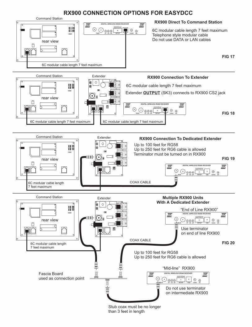
FIG 17
FIG 18
FIG 19
FIG 20
RX900 Direct To Command Station
rear view
DIGITAL WIRELESS RX900 RECEIVER
GPCDST 12VACCS2TBUS AC
FS
1
FS
2
FS
3
B/S
E/R
TB
TM
CS
SETUP
rear view
DIGITAL WIRELESS RX900 RECEIVER
GPCDST 12VACCS2TBUS AC
FS
1
FS
2
FS
3
B/S
E/R
TB
TM
CS
SETUP
Extender RX900 Connection To Extender
6C modular cable length 7 feet maximum
Extender (SK3) connects to RX900 CS2 jackOUTPUT
rear view
DIGITAL WIRELESS RX900 RECEIVER
GPCDST 12VACCS2TBUS AC
FS
1
FS
2
FS
3
B/S
E/R
TB
TM
CS
SETUP
Extender RX900 Connection To Dedicated Extender
Up to 100 feet for RG58Up to 250 feet for RG6 cable is allowedTerminator must be turned on in RX900
rear view
DIGITAL WIRELESS RX900 RECEIVER
GPCDST 12VACCS2TBUS AC
FS
1
FS
2
FS
3
B/S
E/R
TB
TM
CS
SETUP
Extender Multiple RX900 UnitsWith A Dedicated Extender
DIGITAL WIRELESS RX900 RECEIVER
GPCDST 12VACCS2TBUS AC
FS
1
FS
2
FS
3
B/S
E/R
TB
TM
CS
SETUP
Do not use terminatoron intermediate RX900
Use terminatoron end of line RX900
“End of Line RX900”
“Mid-line” RX900
Stub coax must be no longerthan 3 feet in length
Fascia Boardused as connection point
RX900 CONNECTION OPTIONS FOR EASYDCCCommand Station
Command Station
Command Station
Command Station
6C modular cable length 7 feet maximumTelephone style modular cableDo not use DATA or LAN cables
6C modular cable length 7 feet maximum 6C modular cable length 7 feet maximum
6C modular cable length7 feet maximum
6C modular cable length7 feet maximum
Up to 100 feet for RG58Up to 250 feet for RG6 cable is allowed
COAX CABLE
COAX CABLE
6C modular cable length 7 feet maximum
Related Documents