1 EASTERN SUBTERRANEAN TERMITE (ISOPTERA: Reticulitermes flavipes (Kollar)) ENTERING INTO BUILDINGS AND EFFECTS ON THERMAL PROPERTIES OF BUILDING MATERIALS By CYNTHIA LINTON TUCKER A DISSERTATION PRESENTED TO THE GRADUATE SCHOOL OF THE UNIVERSITY OF FLORIDA IN PARTIAL FULFILLMENT OF THE REQUIREMENTS FOR THE DEGREE OF DOCTOR OF PHILOSOPHY UNIVERSITY OF FLORIDA 2008

Welcome message from author
This document is posted to help you gain knowledge. Please leave a comment to let me know what you think about it! Share it to your friends and learn new things together.
Transcript

1
EASTERN SUBTERRANEAN TERMITE (ISOPTERA: Reticulitermes flavipes (Kollar)) ENTERING INTO BUILDINGS AND EFFECTS ON THERMAL PROPERTIES OF
BUILDING MATERIALS
By
CYNTHIA LINTON TUCKER
A DISSERTATION PRESENTED TO THE GRADUATE SCHOOL OF THE UNIVERSITY OF FLORIDA IN PARTIAL FULFILLMENT
OF THE REQUIREMENTS FOR THE DEGREE OF DOCTOR OF PHILOSOPHY
UNIVERSITY OF FLORIDA
2008
2
© 2008 Cynthia Linton Tucker

3
Windswake Farm

4
ACKNOWLEDGMENTS
I would like to express my heartfelt gratitude and appreciation to my academic and
research advisor, Phil Koehler, for his unwavering support. Through careful questioning and
insightful comments he was able to suggest alternative courses of action in experimental and
analytical developments.
I am extremely thankful for the financial support of Dow AgroSciences. I am also
thankful in particular to Ellen Thoms, Raymond Issa, and Richard Patterson who along with Phil
Koehler constituted my supervisory committee and guided the research to a successful end.
I would also like to thank my office mates and compatriots for their unending support. I
would also like to thank Gilman Marshal (the lab’s biological scientist and safety officer) for his
patience and grateful support. Finally I thank my parents and family for their unending support.
And I am grateful for warm summer memories of Windswake Farm.
5
TABLE OF CONTENTS page
ACKNOWLEDGMENTS ...............................................................................................................4
LIST OF TABLES...........................................................................................................................8
LIST OF FIGURES .........................................................................................................................9
ABSTRACT...................................................................................................................................11
CHAPTER
1 INTRODUCTION ..................................................................................................................13
2 LITERATURE REVIEW .......................................................................................................16
Evolution of Termites .............................................................................................................16 Important Subterranean Termites in the United States...........................................................17 Termite Caste System.............................................................................................................18 Process of Tunnel Formation..................................................................................................20 Feeding Habits ........................................................................................................................22 Building Construction and Its Relevance to Termite Exploitation.........................................23 Building Codes .......................................................................................................................23
Building code history ......................................................................................................24 USA code history: ...........................................................................................................24
Concrete Construction Standards ...........................................................................................25 Wood Framing Standards .......................................................................................................27 Termite Control Options.........................................................................................................28 Physical Barriers.....................................................................................................................30 Heat Transfer Concepts ..........................................................................................................31 Insulation ................................................................................................................................33 Thermal Transmission ............................................................................................................33
3 ABILITY OF EASTERN SUBTERRANEAN TERMITES TO MOVE THROUGH CRACKS ................................................................................................................................35
Introduction.............................................................................................................................35 Materials and Methods ...........................................................................................................36
Termites...........................................................................................................................36 Effect of Crack Width on Penetration and Consumption by Caste .................................37 Effect of Termite Head Capsule Dimension on Penetration Through Cracks ................38 Data Analysis...................................................................................................................38
Results.....................................................................................................................................39 Effect of Crack Width on Penetration and Consumption by Caste .................................39 Effect Termite Head Capsule Dimension on Penetration Through Cracks.....................40
Discussion...............................................................................................................................41

6
4 METHODS TO PREVENT PENETRATION OF CONCRETE-PIPE INTERFACES BY THE EASTERN SUBTERRANEAN TERMITE............................................................52
Introduction.............................................................................................................................52 Materials and Methods ...........................................................................................................54
Termites...........................................................................................................................54 Pipe Sleeve Experiment...................................................................................................54
Pipe Sleeve Treatments ............................................................................................54 Pipe Sleeve Experimental Arena..............................................................................55
Termite Blocker Experiment ...........................................................................................56 Treatments ................................................................................................................56 Termite Blocker Experimental Arena ......................................................................57
Data Analysis...................................................................................................................58 Results.....................................................................................................................................59
Pipe Sleeve Experiment...................................................................................................59 Termite Blocker Experiment ...........................................................................................61
Discussion...............................................................................................................................62
5 DEVELOPMENT OF A METHOD TO EVALUATE THE EFFECTS OF EASTERN SUBTERRANEAN TERMITE DAMAGE TO THE THERMAL PROPERTIES OF BUILDING CONSTRUCTION MATERIALS .....................................................................72
Introduction.............................................................................................................................72 Materials and Methods ...........................................................................................................73
Termites. ..........................................................................................................................73 Termite Damage to Construction Materials. ...................................................................74 Thermal Imaging. ............................................................................................................75 Data Analysis...................................................................................................................75
Results.....................................................................................................................................76 2x4s..................................................................................................................................76 Plywood. ..........................................................................................................................77 Rigid Foam Board Insulation. .........................................................................................78
Discussion...............................................................................................................................79
6 EFFECTS OF EASTERN SUBTERRANEAN TERMITE DAMAGE ON THE THERMAL PROPERTIES OF COMMON BUILDING MATERIALS...............................85
Introduction.............................................................................................................................85 Materials and Methods ...........................................................................................................87
Termites...........................................................................................................................87 Test Arena .......................................................................................................................87 Thermal Imaging Setup ...................................................................................................89 Data Analysis...................................................................................................................89
Results.....................................................................................................................................90
7
Structural Lumber............................................................................................................91 Wood Based Siding .........................................................................................................92 Foam Insulation ...............................................................................................................95
Discussion...............................................................................................................................96
7 CONCLUSION.....................................................................................................................117
LIST OF REFERENCES.............................................................................................................119
BIOGRAPHICAL SKETCH .......................................................................................................130

8
LIST OF TABLES
Table page 3-1 Percentage of termite castes located on the bottom of the arena that passed through
various crack widths and consumption of filter paper by termites in arena at 5 d. ...........44
4-1 Effect of pipe sleeve composition and length and termiticide treatment on Mean consumption (g) of cardboard (± SE) on top of the concrete slab by termites. .................65
5-1 Percent damage and surface temperature increase for building materials heated for 15-min. Damaged materials were exposed to eastern subterranean termites (n=300) for 8 wk. .............................................................................................................................81
6-1 Mean ± SE percent termite survivorship, damage (g), percent damage, and percent increase in heat transfer index (HTI) between undamaged and building material damaged by subterranean termites (n=300) and after 8 wk.............................................101
9
LIST OF FIGURES
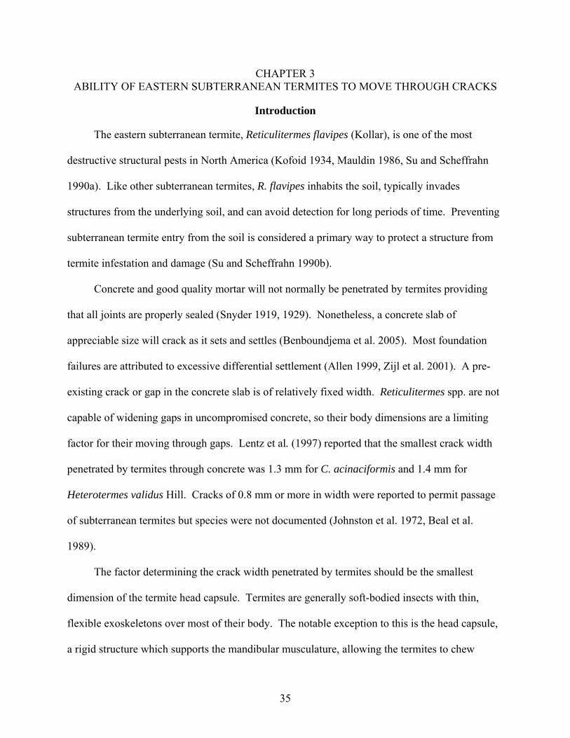
Figure page 3-1 Termite caste location and consumption test arena. ..........................................................45
3-2 Head capsule Petri-dish test arena. ....................................................................................46
3-3 Linear regression comparing the maximum soldier head capsule measurements .............47
3-4 Linear regression comparing the maximum worker head capsule measurements.............48
3-5 Soldier head capsule width. ...............................................................................................49
3-6 Worker head capsule width................................................................................................50
3-7 Larval head capsule width. ................................................................................................51
4-1 Pipe sleeve experimental arena..........................................................................................66
4-2 Termite blocker experimental arena ..................................................................................67
4-3 Typical pipe sleeve experiment arenas at 28 d. .................................................................68
4-4 Foam pipe sleeves exposed to eastern subterranean termites for 28 d in termiticide-treated and untreated arenas...............................................................................................69
4-5 Polyethylene pipe sleeves exposed to eastern subterranean termites for 28 d in termiticide-treated and untreated arenas. ...........................................................................70
4-6 Mean cardboard consumption (g) (± SE) after 8 wk by termites in arenas without termite blocker around copper and CPVC pipes, with or without foam or polyethylene sleeves. .........................................................................................................71
5-1 Images of a 2x4 sample after exposure to 300 termites for 8 wk. .....................................82
5-2 Images of a plywood sample after exposure to 300 termites for 8 wk. .............................83
5-3 Images of a rigid foam insulation sample after exposure to 300 termites for 8 wk...........84
6-1 Differences in heat transfer index between undamaged materials and materials damaged by subterranean termites after an 8 wk period..................................................102
6-2 The 2x4 samples. .............................................................................................................103
6-3 Natural log linear regression of 2x4 samples...................................................................104
6-4 The 2x6 samples. .............................................................................................................105
10
6-5 Natural log linear regression of 2x6 samples...................................................................106
6-6 The OSB samples.............................................................................................................107
6-7 Natural log linear regression of OSB samples.................................................................108
6-8 The T1-11 samples...........................................................................................................109
6-9 Natural log linear regression of T1-11 samples...............................................................110
6-10 The 5-ply samples.. ..........................................................................................................111
6-11 Natural log linear regression of 5-ply samples ................................................................112
6-12 The EXP samples.............................................................................................................113
6-13 Natural log linear regression of EXP samples .................................................................114
6-14 The ISO samples ..............................................................................................................115
6-15 Natural log linear regression of ISO samples ..................................................................116
11
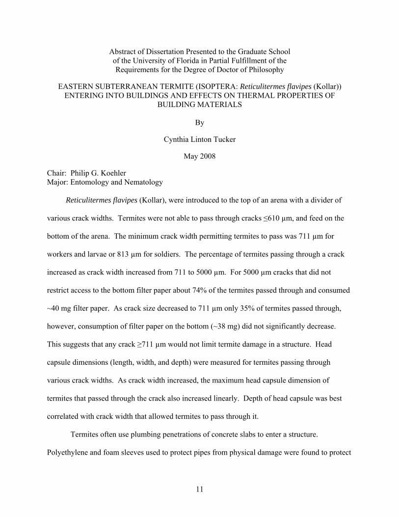
Abstract of Dissertation Presented to the Graduate School of the University of Florida in Partial Fulfillment of the Requirements for the Degree of Doctor of Philosophy
EASTERN SUBTERRANEAN TERMITE (ISOPTERA: Reticulitermes flavipes (Kollar)) ENTERING INTO BUILDINGS AND EFFECTS ON THERMAL PROPERTIES OF
BUILDING MATERIALS
By
Cynthia Linton Tucker
May 2008
Chair: Philip G. Koehler Major: Entomology and Nematology
Reticulitermes flavipes (Kollar), were introduced to the top of an arena with a divider of
various crack widths. Termites were not able to pass through cracks ≤610 µm, and feed on the
bottom of the arena. The minimum crack width permitting termites to pass was 711 µm for
workers and larvae or 813 µm for soldiers. The percentage of termites passing through a crack
increased as crack width increased from 711 to 5000 µm. For 5000 µm cracks that did not
restrict access to the bottom filter paper about 74% of the termites passed through and consumed
~40 mg filter paper. As crack size decreased to 711 µm only 35% of termites passed through,
however, consumption of filter paper on the bottom (~38 mg) did not significantly decrease.
This suggests that any crack ≥711 µm would not limit termite damage in a structure. Head
capsule dimensions (length, width, and depth) were measured for termites passing through
various crack widths. As crack width increased, the maximum head capsule dimension of
termites that passed through the crack also increased linearly. Depth of head capsule was best
correlated with crack width that allowed termites to pass through it.
Termites often use plumbing penetrations of concrete slabs to enter a structure.
Polyethylene and foam sleeves used to protect pipes from physical damage were found to protect
12
termites from residual soil termiticide treatments. When pipe sleeves extended beyond the
termiticide treatment, termites utilized the sleeves as a protected route through the termiticide-
treated sand. However when pipe sleeves terminated within the termiticide treatment, termites
failed to pass through the slab. Impasse™ Termite Blocker installed on pipes prevented termites
from passing through the slab at pipe penetrations.
Building construction materials (2x4s, 5-ply plywood, and rigid foam board insulation)
were exposed to termites for 8 wk and a method for measuring changes in thermal properties was
developed by heating one surface and imaging the temperature on the opposite surface. Termites
mainly tunneled into 2x4s penetrating the sample resulting in ~35% increase in surface
temperature (damaged vs. undamaged samples) despite a small amount of damage (6.7%
consumed). Plywood damaged by termites (3.1% consumed), was the most thermally damaged
with a temperature increase of 74% (damaged vs. undamaged samples). Insulation was
significantly the most damaged with ~12% of the material removed and a temperature increase
of ~27% (damaged vs. undamaged samples).
A heat transfer index was developed to compare thermal properties of termite damaged
building construction materials (2x4 and 2x6 pine lumber, 5 ply plywood, T1-11 siding, oriented
strandboard, extruded polystyrene, and polyisocyanurate insulation). Termite damaged materials
had higher heat transfer indices than undamaged materials The heat transfer index of damaged
2x4 and 2x6 lumber was 37% higher than damaged 5 ply plywood and T1-11 siding: therefore
the siding materials were more thermally resistant. As would be expected the insulation
materials had lower heat transfer index values than the wood materials. Termite damaged
polyisocyanurate was 68% more conductive than the damaged expanded polystyrene insulation.
13
CHAPTER 1 INTRODUCTION
One of the most economically significant pest termites in North America is the eastern
subterranean termite, Reticulitermes flavipes (Kollar). The ability of termites to digest wood and
the consequent potential to cause significant structural damage to most types of buildings
distinguishes termites from the most of other insect pests. The fact that R. flavipes termites live
in colonies of considerable size only serves to increase their destructive potential.
Subterranean termites evolved in nature as decomposers of dead wood. This capacity for
wood digestion, while very useful in terrestrial ecosystems, is a problem for people who build
structures using the same materials that the termites have evolved to feed upon. In geographies
like Florida with high termite activity, specific building codes are required to minimize the
structure’s susceptibility to termite damage. In Florida, the building code also requires a
termiticide-preventative treatment be applied to new construction.
Subterranean termites typically enter structures through the foundation. A concrete slab
may seem impervious, but there are actually numerous potential routes of entry. One entry is the
cracks that inevitably develop as the poured concrete cures and settles. Another entry is where
plumbing pipes and other utilities penetrate the slab to provide a structure with water, power, and
sewer access. Depending upon the space between the pipe and the concrete slab, as well as the
material the pipe is wrapped in, termites may find this space to be an easy point of entry.
The structural damage caused by subterranean termites has been documented extensively
over the years. The focus of this documentation has been the structural weakening of load-
bearing timbers, causing a building to become unsafe and susceptible to collapse. However,
termite damage has other effects that have not been considered. One of these is the change in the
thermal properties of a structure. If the walls of a building are riddled with termite galleries, it

14
stands to reason that heat may travel more easily through damaged walls. Thus, a structure
damaged in this way will lose heat more rapidly in a cold environment, or gain heat more rapidly
in a hot environment. More energy is required for the heating and air conditioning systems to
compensate for the loss of insulating properties. The price of this energy is an added cost of
termite damage.
The first objective in this dissertation is to determine the minimum crack size that R.
flavipes termites can travel through, reviewed in Chapter 3. The next objective concerns the
passage of these termites through spaces between water pipes and a concrete slab, covered in
Chapter 4. The experiments conducted in this chapter will show the effects of different pipe
sleeves on termite travel, as well as the effects of the presence and absence of termite blocker
associated with the pipes. Chapter 4 will also investigate the possibility of pipe sleeves
providing a safe passage for termites through termiticide-treated soil.
The next objective in this dissertation, in Chapter 5, was to establish a method for
determining heat transfer using a hot plate to heat termite damaged and undamaged building
materials to document the change in surface temperature of a sample through time with a thermal
camera. The objective in Chapter 6 was to determine the differences in the rate of heat transfer
between termite damaged and undamaged samples of building materials. Materials will include
structural timbers, wood-based siding products, and foam insulation. These experiments will
show which materials can sustain more damage from termites before losing their insulating
ability, and therefore are best for use in structures located in geographies with high termite
activity.
The final objective of this dissertation is to obtain a better understanding of the activities of
R. flavipes termites within structures. A clearer understanding of their means of entry into

15
structures will allow for more effective prevention of this entry. Knowledge of the termites’
effects on thermal properties will allow a more informed selection of building materials with
reduced adverse effects if damaged by termites. By understanding how subterranean termites
interact with a structure, we may more effectively protect structures from entry and damage by
termites resulting in increased costs to the building occupants.

16
CHAPTER 2 LITERATURE REVIEW
Evolution of Termites
Termites are believed to be closely related to cockroaches and have evolved from an
ancient ancestral cockroach lineage. The most primitive living termite, Mastotermes
darwinensis (Froggatt), has a similar wing structure to cockroaches and females of this termite
species lay their eggs in an ootheca (Snyder 1948). Presently, there is a primitive cockroach,
Cryptocerus punctulatus (Scudder), which burrows into and consumes decaying wood and has
protozoa in its digestive tract similar to those in termites (Guthrie and Tindall 1968). These
similarities suggest that the Order Isoptera diverged from the ancient ancestral cockroach lineage
~200 million years ago (Nalepa and Bandi 2000).
All termites are eusocial insects. Subterranean termites are most commonly found within
the soil, thriving in an environment of high humidity and darkness. Subterranean termites are
also known to invade man-made structures, utilizing the wood within the structures as a food
source (Forschler 1999a). As cryptic, subterranean insects, termite workers are blind and possess
relatively thin, water-permeable exoskeletons. Like most termites, subterranean termites subsist
primarily on cellulosic materials such as wood, roots, and grasses (Waller and LaFage 1987,
Tayasu et al. 1997). Worker termites transfer nutrients to immatures, soldiers and reproductives
via stomodeal and proctodeal trophallaxis. Subterranean termites typically live in large numbers
that can range from 50,000 to several million individuals in a colony (Su et al. 1993). Native
subterranean termites consume numerous species of wood including slash pine, loblolly pine,
and sugar maple (Smythe and Carter 1970). Termites have endogenous enzymes (Watanabe et
al. 1998) and protozoan symbionts in the hindgut (Ohtoko et al. 2000) which allow termites to
digest cellulose and hemicelluloses (Smith and Koehler 2007), reducing these compounds to

17
simple sugars that can be used in energy production. Their digestive processes recycle nutrients
from dead plant materials that few other animals are able to digest (Thorne 1999). Thus,
subterranean termites are ecologically important insects because of their contributions to
environmental cellulose decomposition.
The Order Isoptera has been divided worldwide into seven families (Mastotermitidae,
Kalotermitidae, Sterritermitidae, Hodotermitidae, Rhinotermitidae, Termopside, Termitidae),
281 genera and ~2,600 to 2,761 species (Thorne et al. 2000, Myles 2000, respectively). The
Nearctic region of the world, composed of the U.S.A., Canada, and Northern Mexico, has 38
representative termite species (Eggelton 2000). Weesner (1965) documented the termite
distribution in the U.S.A. and determined that species distribution becomes richer as one moves
south within the U.S.A. Overall, Reticulitermes spp. has the widest distribution in the region.
The most commonly encountered species, Reticulitermes flavipes (Kollar), is a subterranean
termite found throughout the eastern U.S.A. with a range extending from Toronto, Canada
through Florida. This species is a major structural pest capable of forming large colonies and
constructing intricate tunnel networks to provide protection and access to resources.
Important Subterranean Termites in the United States
In the United States, the most economically important subterranean termites are
represented by three genera of the family Rhinotermitidae: Coptotermes, Reticulitermes and
Heterotermes (Light 1934, Kofoid 1946). The genus Reticulitermes contains six species of
termite considered to be economically important (Su and Scheffrahn 1990b). Kofoid (1946)
listed the termites of economic importance in the family Rhinotermitidae included: Heterotermes
aureus (Snyder), R. calipennis (Banks), R. flavipes (Kollar), R. hagani (Banks), R. hesperus
(Banks), R. humilis (Banks), R. lucifugus (Rossi), R. tibialis (Banks), R. virginicus (Banks). In

18
addition, the species Amitermes (Amitermes) wheeleri (Desneux) in the family Termitidae is
considered to be economically important.
The Formosan subterranean termites, Coptotermes formosanus, are an invasive species in
the U.S.A. Since its accidental introduction, C. formosanus has become one of the most
destructive termites in the Hawaiian Islands (Tamashiro et al. 1990). It became established in
Texas, Louisiana, and South Carolina during the 1960s and in Florida in 1980’s (Su and
Scheffrahn 2000).
Termite Caste System
Members of the termite colony are divided into castes, each of which has a specialized
function within the colony. The reproductive caste, consisting of primary reproductives and
secondary reproductives, carry out tasks of reproduction and species distribution. The soldier
caste is responsible for nest and colony defense. Termites in the worker caste carry out the
majority of tasks, such as building and repairing the nest and tending the termite larvae and
reproductives. The needs of the colony determine what individuals will become workers,
soldiers, or reproductives. When there is a suitable balance of these three basic castes, a healthy,
productive, efficient colony can result (Thorne 1999).
Newly hatched larvae are able to develop into any caste in Rhinotermitid termites, but the
persistence of this developmental plasticity varies between different species of termite (Krishna
1969). The earliest instar termites are often referred to as larvae. These larvae, also known as
white immatures, are defined as having no significant cuticular sclerotization (Thorne 1996) and
they are dependent on a liquid diet provided by the workers (McMahan 1969). As the termite
larva molts and matures, the termite’s exoskeleton changes from white to a light tan. This
change is most evident in the head capsule. Third instar workers are referred to as ‘true workers’
if there is no divergence to a soldier or reproductive developmental line (Noirot and Pasteels
19
1988). Soldiers comprise a low percentage of individuals in the colony, approximately 1-2% in
R. flavipes (Howard and Haverty 1980, 1981, Haverty and Howard 1981, Grace 1986, Thorne et
al. 1997) and in R. virginicus (Pawson and Gold 1996). Therefore, the majority of the termites in
the colony are workers (Kofoid 1934).
The division of labor within the colony, in which casts perform specialized tasks, is unique
to social insects and allows the colony to function efficiently to ensure its survival and growth.
Workers are the most numerous caste in the subterranean termite colony and are responsible for
the majority of resource acquisition and nutrient cycling within the colony. Soldiers and larvae
are almost entirely dependent on workers for hydration and nutrients. Workers provide social
grooming to their nestmates during feeding behavior, reducing the chances of bacterial and
fungal growth within the colony. Workers also construct tunnels within the soil and mud tubes
above the soil. Although the soldier caste is primarily responsible for defense, termite workers
are also capable of defending the colony to some extent.
In subterranean termites, the reproductive caste consists of primary and secondary
reproductives (Lee and Wood 1971, Thorne 1999). Primary reproductives play a major role in
the dispersal as alates and founding of colonies, excavation of the first galleries, and feeding and
care of the first young (Light 1934). The primary reproductives consist of males (kings) and
females (queens), which are highly sclerotized, pigmented, have compound eyes, and develop
from winged adults (Krishna 1969). Colony size and maturity are central to determining the
production of winged primary reproductives, or alates (Nutting 1969).
There are three types of secondary reproductives that develop functional reproductive
organs without leaving the parent colony (Lee and Wood 1971). Neotenics develop functional
reproductive organs without becoming alates, and brachypterous neotenics possess wing buds

20
and develop from juveniles that have already developed wing buds (Lee and Wood 1971).
Apterous neotenics do not possess wing buds and develop from juveniles that have not
developed wing buds. Supplementary reproductives act as substitutes for the king or queen if
one or both should die, or supplement the egg production of the queen after the subterranean
termite colony is established (Lee and Wood 1971, Potter 2004). There may be several hundred
supplementary reproductives within the colony because as individuals they are not as prolific as
the queen (Lee and Wood 1971). In Reticulitermes spp., secondary reproductives also help to
expand the foraging territory of the colony (Forschler 1999a). All of the offspring in the colony
are produced by either primary or secondary reproductives. Termite reproductives differ from
those of social Hymenoptera in that the colonies contain ca. 50% males and 50% females
(Kofoid 1934).
Soldier termites are more highly specialized than are the workers. The soldier caste is
traditionally considered the defensive caste (Wheeler 1928, Kofoid 1934). Reticulitermes spp.
soldiers have a distinctively modified head with elongated mandibles. Their mandibles are
effective against certain predators like ants, and certain species have also developed a chemical
defense system (Lee and Wood 1971). Soldier termites develop from a pre-soldier stage that
develops from a larva or worker (Lee and Wood 1971). Soldier termites may act aggressively
toward competitors, predatory ants, and even other termites. Because of the soldiers’ modified
mandibles, soldiers cannot chew wood and are entirely dependent on trophallaxis from worker
termites for food (Traniello et al. 1985, Su and LaFage 1987).
Process of Tunnel Formation
A newly founded colony is usually associated with a wood food source. As time passes,
the colony grows and this food source is consumed the termites must search for additional
resources. Subterranean termites will construct subterranean tunnels and above ground shelter

21
tubes in their search for food resources. Tunneling involves movement of soil particles, and the
process begins with an individual termite. In moist sand, subterranean termites construct the
tunnel network by pushing their heads forward through the moist sand, then pressing the sand
grains from side to side with their head, body, or mandibles (Ebeling and Pence 1957). The
smaller grains of sand are taken into the buccal cavity (Ebeling and Pence 1957), combined with
saliva and feces (Noirot 1970), and cemented to the wall of the tunnel to make a smooth, hard
surface. The termites are also able to carry sand grains to the surface to deposit excess soil
particles or construct above ground shelter tubes.
Above ground shelter tubes may be constructed during the search for food and after an
adequate food source has been located. Above ground foraging begins with the movement of
termites on the surface of the soil, trees, buildings, or other structures. As the termites search,
they may find nearly any type of cellulosic material to be an adequate food source, including a
wooden structure (Ebeling 1975). In the process of searching above ground, the termites leave a
faint pheromone trail (Stuart 1969, Runcie 1986). Once a food source has been located, the
chemical trail is reinforced with additional pheromone, causing other termites to be recruited to
the food source (Thorne 1996). Deposits of chewed cellulose, soil, feces and saliva are laid at
the food source and the tunnel network opening. Soldiers can be seen at the openings as the
workers quickly build the shelter tube (Snyder 1948, Reinhard et al. 1997). The completed
shelter tube protects the termites from predators and desiccation. The shelter tubes may not
protect the termites during extreme temperature changes, and they may retreat to the more stable
environment of their subterranean tunnel network (Potter 2004).
The subterranean tunnel network provides the termite colony with a protected route of
travel, giving them access to food and moisture resources. As the colony grows and searches for
22
food, the tunnel network increases in size. Tunnel construction in the soil does not initially begin
with the deposition of a trail pheromone, as is the case of above ground shelter tube construction.
Tunneling simply begins with the movement of soil particles (Ebeling and Pence 1957). After
tunnel construction, pheromones for trailing and recruitment are laid inside tunnels to direct
termite activity.
Tunnel construction may be described as non-random and may be influenced by
temperature, moisture gradient, food sources (Ettershank et al. 1980), guidelines (Pitts-Springer
and Forschler 2000) and soil compaction (Tucker et al. 2004). Puche and Su (2001c) found no
indication that R. flavipes were able were able to detect wood in sand over distance. However,
the excavation of new tunnels and the movement of the termites within existing tunnels network
are both essential for resource acquisition. Once tunnels are constructed to resources, individual
termites may randomly select which resources to forage on (Su et al. 1984, Jones et al. 1987).
Feeding Habits
The food gathered by worker termites is the basic energy source of the colony (Lee and
Wood 1971). It consists of living or dead plant material that is either partially or almost entirely
decomposed (Lee and Wood 1971). Subterranean termites may feed on a wide variety of food
including sound wood, decaying wood, parts of living trees and shrubs, plants, books, cardboard,
and paper. The major nutritional ingredient in all of these foods is cellulose (Noirot and Noirot-
Timothee 1969). Cellulose, a carbohydrate continuously produced by plants, is the most
common organic compound on earth and is an abundant potential food source (Light 1934).
Subterranean termites may also chew through non-nutritive materials such as foam
insulation (Gyuette 1994, Smith and Zungoli 1995abc, Ogg 1997), plastic, and rubber products
(Sternlicht 1977). Subterranean termites have also been known to damage or penetrate drywall,
plaster, and even stucco (Potter 2004).
23
Termite soldiers and larvae, as well as some nymphs and reproductives, are unable to feed
themselves and are fed via stomodeal and proctodeal trophallaxis from the workers. Proctodeal
feeding occurs in the lower termites that contain protozoan intestinal fauna (Wheeler 1928,
Noirot and Noirot-Timothee 1969). It consists of liquid excretions from the rectal pouches.
Proctodeal feeding allows larvae to ingest the protozoa necessary for cellulose digestion, and
allows gut refaunation in worker termites after a molt (Wheeler 1928). Stomodeal food may
often be regurgitated as clear liquid (probably saliva) and is the only way reproductives can get
nourishment (Noirot and Noirot-Timothee 1969).
Building Construction and Its Relevance to Termite Exploitation
Subterranean termite control begins by excluding termites from a structure, thereby
preventing them from damaging building materials by their feeding and tunneling.
Understanding the relationship between termite biology and construction design is essential to
termite control and the prevention of termite damage within a structure. The best time to provide
protection against termites is during the planning and construction of the building. Improper
design and construction of buildings, resulting from lack of knowledge or indifference to termite
problems, can greatly increase the chances of termite infestation. Building codes set a standard
that allow for flexibility of termite treatment options and protection against termites.
Building Codes
Building code is a set of rules that specify the minimum acceptable level of safety for
constructed objects such as buildings and other structures. The main purpose of the building
codes is to protect public health, safety and general welfare as they relate to the construction and
occupancy of buildings and structures (IBC 2006). The building code becomes law of a
particular jurisdiction when formally enacted by the appropriate authority.
24
The relevance of establishing building code standards is to protect a structure and the
property owner from avoidable property loss due to structural failure (Allen 1999). Subterranean
termites can damage the structural load bearing members by tunneling into the wood. They can
also tunnel into and damage wooden sheathing and insulation products affecting the building
envelope.
Building code history: For thousands of years, building codes and regulations have
protected the public. The earliest known code of law referred to as The Code of Hammurabi,
king of the Babylonian Empire, written in 2200 B.C. assessed severe penalties, including death,
if a building was not constructed safely. The regulation of building construction in the United
States dates back to the 1700s. By the early 1900s, special interest groups, such as the insurance
industry, joined others with similar concerns to develop a model code. This first model building
code gained widespread popularity among legislative authorities (Kofiod 1934).
USA code history: Since the early 1900s, the system of building regulations was based on
three regional model codes: the Building Officials Code Administrators International (BOCA),
Southern Building Code Congress International (SBCCI), and the International Conference of
Building Officials (ICBO) (Miller et al. 2002). Although the regional code development has
been effective and responsive to the regulatory needs of the local jurisdictions, in the early 1990s
it became obvious that the country needed a single coordinated set of national model building
codes. The nation’s three regional model code groups decided to combine their efforts and in
1994 formed the International Code Council (ICC) to develop codes that would have no regional
limitations (IBC 2006).
The first edition of the International Building Code was published in 1997. By the year
2000, International Code Council has completed the International Codes series and ceased
25
development of the legacy codes in favor of their national successor. The International Building
Code applies to all structures in areas where it is adopted, except for one and two family
dwellings, which falls under the International Residential Code (IBC 2006).
Parts of the International Building Code reference other codes including the International
Plumbing code, International Mechanical code, National Electric Code and various National Fire
Protection Association Standards. Therefore, if a municipality adopts the International Building
Code, it is adopts those parts of the other codes referenced by the International Building Code.
Often, the plumbing, mechanical, and electric codes are adopted with the Building Code.
Currently the International Building Code has been adopted by 45 states. Each state has their
own state and local codes that tailor the International Building Code and International
Residential Code to suite the uniqueness of the state and region (IBC 2006, Miller et al. 2004).
Concrete Construction Standards
Building foundations and concrete minimum building standards are addressed in the codes
(IBC 2006). One primary function of a foundation is to transfer the structural loads from a
building safely into the ground. The foundation design is an integral part of every building. The
foundation supports a number of different kinds of loads: dead, live, wind, and snow loads (Allen
1999). If the concrete is not strong enough or the ground below settles, the concrete may crack
allowing subterranean termites to access the structure from below. Termites entering the
structure from cracks hidden from the exterior foundation may go undetected for a long period of
time and may result in significant termite damage to the structure. Currently the building code
requires the concrete slab to be a minimum of 150 cm above grade to allow a termite inspection
area around the structure (IBC 2006).
A satisfactory foundation for a building should meet three general requirements. First, the
foundation, including the underlying soil and rock, must be safe against structural failure that

26
could result in collapse. Second, during the life of the building, the foundation must not settle in
such a way to damage the structure or impair its function. Finally, the foundation must be
feasible both technically and economically, and practical to build without adverse effects to
surrounding property. Satisfying the aforementioned requirements of a foundation would
minimize the risk of concrete cracking, reducing the possibility of undetected subterranean
termite entry into a structure.
A concrete foundation can be considered an initial barrier to termites if there are no
concealed cracks. The Australian Standard AS 3660.1 specifies for buildings constructed on
sub-floors that the concrete slab can form an integral part of the termite barrier system (AS
1995). Lentz et al. (1997) reported that cracks ranging from 0.5-4.0 mm, made by splitting slabs,
can allow termite access through the slab. They determined that the smallest crack width
penetrated varied by termite species, and was 3.1 mm for Coptotermes acinaciformis, 1.5 mm for
Sherorhinotermes breinli, 1.8 mm for Heterotermes vagus, and 1.4 mm for H. validus.
Minimum concrete strength standards are established by the building codes to reduce the
potential for foundation shrinkage and cracking (IBC 2006).
The quality of a building floor or slab made of concrete is highly dependent on achieving a
hard and durable surface that is flat, relatively free of cracks (ACI 2004). There are several
components that contribute to the properties of the final product, such as mixture ratios, quality
of concreting, and joining techniques. The timing of the concreting operations, especially
finishing, jointing, and curing, is critical. Failure to address foundation and concrete design can
result in unsatisfactory characteristics in the wearing surface such as cracking, low resistance to
wear, dusting, scaling, high or low spots, poor drainage, and increased potential for curling.
27
Concrete floor slabs using portland cement, regardless of consistency, will start to
experience a reduction in volume as soon as they are placed and will continue al long as water
and/or heat are released to the surroundings. Because of the drying and cooling rates are
dissimilar at the top and bottom of the slab, the shrinkage will vary throughout the depth,
possibly causing the final product to be critically distorted and reduced in volume.
The American Concrete Institute (ACI) has published a guide containing recommendations
for controlling random cracking and edge curling (ACI 2004). ACI also acknowledges that even
with the best foundation design and proper construction techniques; it is unrealistic to expect
crack-free and curl-free concrete floor slabs. Therefore, it should be expected that some cracking
and curing to occur on every project and that such occurrences may not adversely impact the slab
adequacy if the design or the quality of the construction is sufficient (Campbell et al. 1976,
Ytterberg 1987). Therefore, since concrete cracking and shrinkage is always possible, then other
termite control measures should be employed.
Wood Framing Standards
Minimum standards for single and multi-family dwellings are established in the
international building code (IBC 2006). Design of exterior wall framing must be adequately
sized for strength and support. Exterior walls must be strong enough to support both live and
dead loads. Walls must also be able to resist lateral wind loads and in some regions, seismic and
hurricane forces (Allen 1999, Miller et al. 2002). Top plates are doubled and lapped at corners
and at bearing partition intersections to tie the building into a strong structural unit. In addition
to establishing minimum standards for strength and design of wood framing, standards have also
been established to prevent termite infestation.
The building codes establish minimum standards for termite prevention and control to
protect the materials in service from current and future termite attack. Because termites can
28
readily damage and consume cellulose products, a wooden structure needs to be protected.
When wood is in contact with the soil, the building code allows the use of termite resistant wood,
in critical termite prone areas, such as yellow cypress (Chamaecyparis nootkatensis), western red
cedar (Thuja plicata) and eastern white cedar (Thuja occidentalis) (IBC 2006), these species of
wood have natural substances that prevent termite attack. Grace and Yamamoto (1994)
determined that the heartwood of Chamaecyparis noothatensis (yellow cypress, or Alaska cedar)
and Chamaecyparis obtuse (hinoki) resists attack by the Formosan subterranean termite. Also,
wood construction components can be protected against decay and termite attack by application
of chromated copper arsenate (CCA) (Grace 1998), ammoniacal copper quat (ACQ), copper
azole (CA), or copper, zinc and arsenic ammonia (AZQA) (Tamashiro et al. 1988).
The studs in exterior walls of one and two-story structures are at least 2x4 inches with the
4-inch dimension forming the basic wall thickness. Stud spacing is normally 16 inches in
exterior walls. The studs are arranged in multiples at corners and partition sections to provide
the rigid attachment of sheathing (Allen 1999).
The high resistance of wood frame construction to seismic, hurricane and other natural
forces of nature are provided when exterior sheathing adequately secured to the exterior wall
stubs. Exterior wall sheathing includes plywood, particle board, and other structural panels such
as oriented strandboard, structural insulation, and board lumber. Sheathing is applied in strict
accordance with manufacturers nailing requirements to provide a rigid wood frame system. All
wooden materials that are not naturally termite resistant should be protected against termite
attack to maintain their strength and other physical properties (IBC 2006).
Termite Control Options
Currently there are four major categories of termiticide treatments to protect structures
from subterranean termites; liquid soil termiticides, wood-applied termiticides, baiting systems,
29
and physical barriers. Liquid termiticides are typically classified as repellent or non-repellent
and have been used to exclude subterranean termites from structures. Pyrethroids are among the
most commonly applied soil termiticides for new construction, and are highly repellent to
subterranean termites, deterring termites from tunneling in treated soil without causing
significant mortality (Su et al. 1993). Soil termiticides are applied to the soil beneath and around
the structure to create a barrier (Su and Scheffrahn 1990a). The newer, non-repellent
termiticides include imidacloprid (Kuriachan and Gold 1998), fipronil (Osbrink et al. 2001), and
chlorofenapyr (Rust and Saran 2006), all of which are effective at killing subterranean termites.
Soil termiticide treatments have been used since the 1900s and are generally inexpensive
and easy to use. A soil termiticide treatment is applied during the construction of a building, and
is required by the building code in Florida unless another method of termite protection is
approved as a stand-alone treatment (FBC 2004). Liquid soil termiticides are also used for
remedial treatments. Currently available soil termiticide treatments degrade and may require
reapplication after five or more years (Su et al. 1999, Richman et al. 2006) to maintain long-term
protection of structures.
In Florida, currently registered termite baiting systems approved for application at new
construction contain hexaflumuron (Foos 2006), noviflumuron (Foos and Daiker 2003), or
diflubenzuron (FBC 2004). These compounds are chitin synthesis inhibitors (CSIs) that prevent
the successful molting and development of subterranean termites. This disruption in termite
growth causes the decline of the colony to the point of colony death. Hexaflumuron, the most
extensively studied CSI active ingredient, has been proven to eliminate subterranean termite
activity with several species of subterranean termites (Su 1994, Clement et al. 1996, Su and
Scheffrahn 1996, Peters and Fitzgerald 1999, Sajap et al. 2000, Rojas and Morales-Ramos 2001,
30
Grace and Su 2001). Noviflumuron, also produced by Dow Agrosciences, can eliminate
colonies of Reticulitermes in about half the time as colonies baited with hexaflumuron (Smith et
al. 2002). Karr et al. (2004) reported that the lethal dose of noviflumuron for R. flavipes termites
was found to be at least two-to three-fold lower than that of hexaflumuron. Su and Scheffrahn
(1993) determined that R. flavipes and C. formosanus consumed diflubenzuron resulting in
>90% mortality for both species in 9 wk.
Physical Barriers
Physical particle barriers of impenetrable materials, such as sieved soil particles (Ebeling
and Pence 1957, Su and Scheffrahn 1992, Yates et al. 2000) and steel mesh (ABSAC 1992,
Grace et al. 1996, Lentz and Runko 1994), have been demonstrated to effectively exclude
subterranean termites. For physical barriers to be effective, they must be constructed of
materials that cannot be moved or chewed through by termites and create no gaps that termites
can move through. Sieved soil particles must be specific size range to be large enough to prevent
manipulation by termite mandibles and small enough to not provide gaps to allow termite
movement through. Research has documented the effective size range for a soil particle barrier
is dependent upon the head capsule width of the termite species. Tamashiro et al. (1987, 1991)
documented that Coptotermes formosanus Shiraki could not penetrate basaltic particles with
diameters in the range of 1.7-2.4 mm. Su et al. (1991) found that particle barriers of 1.18-2.80
mm in size effectively prevented penetration of both R. flavipes and C. formosanus.
A physical barrier made of a fine stainless steal mesh wire known as “Termimesh®” was
developed in the early 1990s (ABSAC 1992, Lentz and Runko 1994). Termimesh is typically
placed in critical areas, such as along control joints and around pipe penetrations, before the
concrete slab is poured. This mesh wire barrier, with an aperture of 0.45 by 0.66 mm, has been
proven effective to prevent access of large termites such as, C. formosanus (Grace et al. 1996),

31
C. acinaciformis (Froggatt), Mastotermes darwiniensis Froggatt, and Schedorhinotermes breinli
(Hill) (Lentz and Runko 1994). Smaller termites, such as Heterotermes vagus (Hill) with a
maximum head width of only 0.76 mm, were able to move through this mesh wire (Lentz and
Runko 1994).
Impasse® (Syngenta Crop Protection, Greensboro, NC) is an insecticide-impregnated
vapor retarder that contains the pyrethroid lambda-cyhalothrin sandwiched between construction
grade polymer layers. Like Termimesh, Impasse is used to repel termites from cracks in the slab
or gaps created plumbing or utility penetrations (Harbison 2003, Wege et al. 2003). Impasse
barrier became available in 2002 with the intent to cover the entire undersurface of the
foundation. Su et al. (2004) found that Impasse placed over a sand plot and covered with a
concrete slab prevented termite penetration. The Impasse termite system later focused on
Impasse termite blocker, installed around plumbing and utility pipes penetrating the slab.
Impasse termite blocker is applied in the preconstruction phase and is embedded in the concrete
around the pipe penetrations when the building foundation is poured.
Heat Transfer Concepts
Heat is a form of energy that is sometimes expressed as the intensity of molecular vibration
within a material. Heat is always transferred in the direction of decreasing temperature. There
are three different types of heat transfer: radiation, convection, and conduction. In all cases, a
temperature difference must exist for heat transfer to occur (Bueche and Wallach 1994).
Radiation is the movement of energy by means of electromagnetic waves. Radiative heat
transfer does not require that objects be touching to transfer heat (Bueche and Wallach 1994).
Convective heat transfer occurs when a fluid, as a liquid or a gas, comes in contact with a
material of a different temperature. Natural convection occurs when the changes in the localized
densities of a fluid, due to differences in thermal energy, drive the flow of the fluid. Forced

32
convection occurs when the fluid flow is due to localized differences in pressure (Bueche and
Wallach 1994).
Conduction takes place within the boundaries of a solid body by the transfer of thermal
energy between molecules within the material. The rate at which heat is conducted through a
material is proportional to the area available to the heat flow and the temperature gradient along
the heat flow path. For a one-dimensional, steady state heat flow the rate is expressed by
Fourier’s equation (Healy and Flynn 2002):
Q=k*A*(ΔT/d)
Where:
k=thermal conductivity, W/m-K Q=rate of heat flow, W A=contact area, m d=distance of heat flow, m ΔT=temperature difference, Kelvin
Thermal conductivity, k, is an intrinsic property of a material which describes the
material’s ability to conduct heat (ASHRAE 2005). This property is independent of the
materials size, shape, or orientation. For non-homogeneous materials the term “relative thermal
conductivity” is generally used and is appropriate because the thermal conductivities depend on
the thickness of the layers and their orientation with respect to heat flow. Another inherent
thermal property of a material is its thermal resistance, R or R-value (Bueche and Wallach 1994),
as defined below:
R=A*(ΔT/Q)
Resistance is a measure of how a material of a specific thickness resists the flow of heat.
The relationship between k and R is shown by combining the previous two equations to form:
k=d/R
33
This equation shows resistance is directly proportional to the material thickness for solids
(Bueche and Wallach 1994).
Insulation
The use of cellular thermal insulation has increased in recent years due to its energy saving
potential. There are many organic and inorganic substances that are capable of being processed
to form stable cellular foam insulation. In order to be successfully processed, the substance must
have the capability of being processed as a fluid, mechanically expanded by foaming with a gas
while in a liquid state, and then solidified while maintaining a cellular matrix established during
the foaming process. Rigid cellular materials are most often used for thermal insulation within
structures, but flexible and semi-rigid materials are available. The most common types of
organic, cellular insulations are manufactured using polyurethane and polyisocyanurate, and
resins of polystyrene, urea-formaldehyde, and phenol-formaldehyde. The most common
inorganic, cellular insulation (Perlite and vermiculite) is produced from glass (Yost 1991).
Thermal Transmission
The most important physical property of cellular thermal insulation is thermal
transmission. In cellular insulations, thermal energy is transferred by three different
mechanisms: conduction through the solid portion of the foam, conduction through the gaseous
portion, and radiation through the cellular matrix from cell wall to cell wall (Skochdopole 1961).
Convection heat transfer within cells is generally not considered, because the cell size is usually
too small to support significant convective movement (Skochdopole 1961).
For many products, measures are taken to minimize the heat transfer contribution from one
or more of these mechanisms. For example, chlorofluorocarbon blowing agents are commonly
introduced not only to help foam the fluid but also to reduce conduction through the gaseous

34
portion of the foam. The use of facings laminated or bonded to chlorofluorocarbon-blown foams
can also decrease thermal transfer.
One method of minimizing radiation through the cellular matrix is to increase the foam
density, thus providing more material in the cell walls to absorb infrared radiation. Although an
increase in density can reduce the radiation component of heat transfer, it simultaneously
increases the conduction through the solid portion of foam. Therefore, the lowest thermal
transfer for a particular foam material can be found in the optimal balance of solid and gaseous
portions within the cellular matrix. For example, the optimum balance for cellular plastics is
generally 1.8 to 2.5 lb/ft3 (28.8 to 40.0 kg/m3) (Skochdopole 1961, Norton 1967, Booth and Lee
1985). However, other factors generally need to be considered, such as raw material costs and
mechanical strength requirements, so the density of the cellular products typically ranges from
1.0 to 4.0 lb/ft3 (16 to 64.0 kg/m3).
35
CHAPTER 3 ABILITY OF EASTERN SUBTERRANEAN TERMITES TO MOVE THROUGH CRACKS
Introduction
The eastern subterranean termite, Reticulitermes flavipes (Kollar), is one of the most
destructive structural pests in North America (Kofoid 1934, Mauldin 1986, Su and Scheffrahn
1990a). Like other subterranean termites, R. flavipes inhabits the soil, typically invades
structures from the underlying soil, and can avoid detection for long periods of time. Preventing
subterranean termite entry from the soil is considered a primary way to protect a structure from
termite infestation and damage (Su and Scheffrahn 1990b).
Concrete and good quality mortar will not normally be penetrated by termites providing
that all joints are properly sealed (Snyder 1919, 1929). Nonetheless, a concrete slab of
appreciable size will crack as it sets and settles (Benboundjema et al. 2005). Most foundation
failures are attributed to excessive differential settlement (Allen 1999, Zijl et al. 2001). A pre-
existing crack or gap in the concrete slab is of relatively fixed width. Reticulitermes spp. are not
capable of widening gaps in uncompromised concrete, so their body dimensions are a limiting
factor for their moving through gaps. Lentz et al. (1997) reported that the smallest crack width
penetrated by termites through concrete was 1.3 mm for C. acinaciformis and 1.4 mm for
Heterotermes validus Hill. Cracks of 0.8 mm or more in width were reported to permit passage
of subterranean termites but species were not documented (Johnston et al. 1972, Beal et al.
1989).
The factor determining the crack width penetrated by termites should be the smallest
dimension of the termite head capsule. Termites are generally soft-bodied insects with thin,
flexible exoskeletons over most of their body. The notable exception to this is the head capsule,
a rigid structure which supports the mandibular musculature, allowing the termites to chew
36
through hard substrates like wood. This rigidity makes the head capsule incapable of being
compressed. Therefore, for a termite to travel through a crack, the smallest dimension of the
termite head capsule must be less than the width of the crack. Movement through a crack would
restrict movement in one-dimension where as movement through particles or a mesh would
restrict movement in two-dimensions. The only study correlating termite body dimensions to
movement through various particle sizes was Su et al. (1991). No studies have been conducted
evaluating the ability of different termite developmental stages for passing through fixed crack
widths.
The objectives of this study on R. flavipes were to investigate the relationship between
crack width and head capsule size for both worker and soldier termites, and evaluate the ability
of different termite developmental stages to pass through cracks of different widths and
subsequent consumption of matrices on either side of the cracks.
Materials and Methods
Termites
Three colonies of R. flavipes, separated by more than 1.5 km in Gainesville, FL, were
field collected in 6-liter plastic buckets inserted below ground with their lids accessible above the
soil surface. Each bucket was filled with 2-3 moistened corrugated cardboard rolls (15 cm long
by 10 cm diam.; Gainesville Paper Co., Gainesville, FL). Termites accessed cardboard rolls
through ~10 holes (4-cm diam.) in the sides and bottom of each bucket. Cardboard rolls
containing termites were collected and returned to the lab in Ziploc bags (3.8-L). Termites were
removed from the cardboard by gently separating the corrugated cardboard and allowing the
termites to fall into a 20-L plastic bucket. The termites were then placed on moistened
corrugated cardboard and reared at room temperature (~23°C) in plastic boxes (27 by 19 by 9.5
cm) with moistened cardboard for ≤1 wk before inclusion in experimental arenas.

37
Prior to the test, termites were sorted by size and caste. Soldiers and workers were
separated from larvae using a 1.18 mm mesh soil sieve (No. 16, Fisher Scientific Company,
Pittsburgh, PA). Larvae through the 2nd instar passed through the sieve. The 2nd instar larvae
were then separated from white immature larvae using a vacuum aspirator.
Effect of Crack Width on Penetration and Consumption by Caste
The test arena to evaluate penetration by caste and consumption by crack width was an
acrylic plastic cylinder (5.08 cm I.D., 127 cm long) with an acrylic divider (1.59 cm thick)
placed 5.72 cm from the bottom (Fig. 3-1). An oval opening (1 by 0.5 cm) was cut into the
center of the acrylic divider. Two aluminum spacers (2.5 by 1.0 by 0.1 cm) were glued over the
oval opening to create a space 1 cm long. Crack widths of 406, 508, 610, 711, 813, 991, and
5,000 µm were created using spark plug feelers (Carquest Corp., Lakewood, CO) and a second
acrylic divider with oval opening was glued over the aluminum plates before the glue set to fix
plates in place.
Soil was oven-dried at ~177°C for 24 h, sifted through a 1.18 mm mesh soil sieve to
remove debris, and moistened by mixing 40 ml of distilled water in 400 g soil. Moistened soil
was evenly distributed above and below the acrylic dividers within the experimental arena
leaving a 0.64 cm void on the top for termite introduction. Pre-weighed filter paper (Whatman
#4, ~130 mg, 4.3 cm diam.) was placed on the top and bottom of the arena.
Termites were aspirated into groups of 253 insects, consisting of 3 soldiers, 200 workers
[≥3rd instar], 50 larvae [2nd instar], that were introduced on top of each arena. The top and
bottom of the arena were lidded with a plastic Petri dish (100 mm diam.) and secured with two
rubber bands. The experiment was a randomized complete block design. Each crack width (n =

38
7) was evaluated using three termite colonies with four replications per colony, resulting in 84
experimental arenas.
The arenas were opened 5 d after setup, and the numbers of each caste of termites located
in the top and the bottom sections were counted. Filter paper was collected, oven dried, and
weighed to determine consumption.
Effect of Termite Head Capsule Dimension on Penetration Through Cracks
The arena to evaluate the termite head capsule dimensions and crack width was a Petri dish
(55 mm diam.) with an acrylic divider and aluminum plates built as described above. Crack
widths of 711, 813, and 991 µm, and were created using spark plug feelers (Carquest Corp.,
Lakewood, CO) (Fig. 3-2). Groups of 125 termites consisting of 45 soldiers, 60 workers [3rd
instar] and 20 larvae [2nd instar] were then introduced to the arena above the crack. The arena
was lidded and sealed with Parafilm “M” (Pechiney Plastic Packing, Chicago, IL). Each crack
width (n = 3) was evaluated using three termite colonies with three replications per colony,
resulting in 27 experimental arenas.
The arenas were opened 24 h after setup, and the numbers of each caste of termites located
in the top and the bottom sections were recorded. The termites from the top and bottom sections
were separated and chilled in a refrigerator for ~30 minutes before measuring. The termites head
capsule width, length, and depth were measured using a dissecting microscope with a calibrated
ocular micrometer.
Data Analysis
In the test arena to evaluate penetration and consumption the percentage of the termites
that passed through each crack width and survivorship in the arena were arcsine transformed and
analyzed with two-way analysis of variance, (P = 0.05; SAS 2001), with termite colony and
crack width as main effects, and were separated with Student-Newman Keuls (SNK). The effect

39
of crack width and termite colony consumption (gm) filter paper total and filter paper on bottom
of arena were analyzed using one-way analysis of variance (ANOVA) and were separated with
Student-Newman Keuls (SNK), (P = 0.05; SAS 2001).
Quantiles of the head capsule width and depth for each caste were determined using
univariate analysis (SAS 2001) for the total population of termites and termites found below the
crack. Also for the soldier and worker termites located on the bottom of the Petri-dish a linear
regression was performed to determine the relationship of maximum head capsule measurements
(length, width, and depth) and the termite’s ability to pass through three crack widths to the
bottom of the arena.
Results
Effect of Crack Width on Penetration and Consumption by Caste
Termites began tunneling immediately after introduction to the top of the arena and lived
to the end of the test with no significant mortality. Survivorship for each caste averaged 96% for
larvae, 97% for workers, and 99% for soldiers. The percentage (number) of termites passing
through a crack increased as the crack width increased (Table 3-1). No termites were able to
pass through the smallest crack widths of 406 and 508 µm. Only one larva was able to pass
through the crack width of 610 um. The minimum width opening permitting functional access
by each caste was 711 µm for workers and larvae and 813 µm for soldiers. The dimensions of
711 and 813 µm did restrict movement of caste members because the proportion of each caste
that passed through these dimensions were significantly less than those passing through gaps of
991 µm or greater.
Crack widths of 610 µm and less that prevented penetration by termite workers
subsequently prevented feeding on the bottom of the arena (Table 3-1). There was significantly
more paper consumed, total and in the bottom of the arena, for crack dimensions ≥711 µm

40
compared to crack dimensions ≤610 µm. There was no significant difference in paper
consumed, total or in the bottom of the arena, for cracks from 710 – 5,000 µm in width, even
though a significantly lower proportion of workers were found in the bottom arenas with crack
widths of 711 and 813 µm.
Effect Termite Head Capsule Dimension on Penetration Through Cracks
Termite groups placed in the Petri-dish arena immediately began to move about the arena
seeking a more hospitable environment. Termites were given two options, to stay on the surface
with no food or protection above the crack or to pass through the crack (711, 813, and 991 µm)
in search of food and protection. Linear regression analysis of termite head capsule dimensions
(length, width, and depth) of termites able to pass through the three crack widths indicated a
positive relationship between crack width and head capsule dimensions for both solders and
workers (Figure 3-3 and 3-4, respectively). As crack width increased, the maximum head
capsule dimension of termites that passed through the crack also increased. The head capsule
dimension of depth, compared to length and width, had the best correlation to crack width, with
r2 values of 0.96 for soldiers and 0.92 for workers.
Greater than 75% of the soldiers (Fig. 3-5, A) and 50% of the workers (Fig. 3-6, A) had
head capsule widths greater than the width of the crack that they passed through. In contrast, the
head depth of 100% soldiers (Fig. 3-5, B) and workers (3-6, B) was always ≤ to 991 or 813 µm
wide cracks they passed through. A low percentage of soldiers (10%) and workers (25%) with
head depths greater than 711 µm were able to pass through cracks of this width. No larvae had
head capsule depths larger than the most narrow crack width of 711 µm (Fig. 3-7, B), so smaller
width cracks would need to be tested to evaluate penetration by larvae. These data further
41
confirm that head capsule depth is the best predictor of a termite’s ability to penetrate fixed crack
widths.
Discussion
Previous studies have identified the termite head capsule width, not depth, as a significant
factor in the termite being able to penetrate through physical barriers (Su et al. 1991, Lenz and
Runko 1994, Grace et al. 1996, Toutountzis 2006). Su et al. (1991) suggested that one colony of
C. formosanus was not able to move through the interstitial space of large particles forming a
uniform particle barrier because the workers and soldiers had a large head capsule width (1.4
mm). Termi-Mesh® is marine grade stainless steel wire screen (ABSAC 1992, Lentz & Runko
1994) which is embedded in concrete during construction to form a physical barrier to termites
(AS 1995). Grace et al. (1996) found that the Termi-Mesh screen with a rectangular aperture
size of 660 by 450 µm was able to exclude Coptotermes formosanus Shiraki from all test units.
Another study found that smaller termites, such as Heterotermes vagus (Hill) workers with a
head width of ~0.76 mm, were able to pass through the small Termi-Mesh screen (Lentz and
Runko 1994), perhaps by aligning the head capsule to the largest dimension of the rectangular
aperture, the hypotenuse measuring ~799 µm. Our study determined the termite head depth, not
head width, is the limiting factor in determining a termite’s ability to pass through the small
cracks of fixed width.
Our study findings concur with previous recommendations that no cracks greater than
0.396 mm (1/64 inch) should be present in the foundation and between masonry units
(Anonymous 1980). Our study also supports previous reports that termites can penetrate cracks
that are 0.794 mm (1/32 inch) wide (St. George et al. 1960). Our conclusions were based on
head capsule measurements for R. flavipes workers and soldiers, which were consistent with
those previously reported. Banks (1946) documented R. flavipes soldiers have a head capsule

42
lengths of 1.7-2.3 mm, head capsule widths of 1.0-1.3 mm, and head depths of 0.85-1.1 mm.
Similar soldier head capsule measurements for R. flavipes were also found by Scheffrahn and Su
(1994) and Thorne et al. (1997). The mean morphological worker head capsule measurements
collected from four field colonies of R. flavipes, were head length of 1.2 mm and width of 1.0
mm (Su et al. 1991).
Our study found that termites consumed significantly less filter paper in arenas where they
were confined to the top of the arena (~40 mg) than in arenas where termites accessed the top
and bottom through the crack (~64 mg). Cornelius (2003) found that R. flavipes wood
consumption rates were greater on large blocks of wood than on small blocks of wood. Similar
results were found when food consumption rates were measured for different combinations of
wood volume and termite group size. Lentz et al. (2003) found that subterranean termites, R.
speratus (Kolbe), consumed 20% more when provided a food source that was 75% larger in size.
These studies as well as this study support the concept that subterranean termites vary their
feeding in response available resources. Another plausible explanation for the greater filter
paper consumption is that the energy expense of establishing a new tunnel network was
compensated for by consuming more filter paper.
Even though the proportion of termite workers passing through crack widths of 711 and
813 µm were significantly less than those in the 991 and 5,000 µm crack width arenas, the total
consumption of the filter paper was not significantly different in arenas with crack width ranging
from 711 to 5,000 µm. This suggests that, for the 711 and 813 µm crack width arenas, the
worker termites able to reach the bottom of the arena efficiently transferred larger amounts of
food to nestmates confined to the top of the arena. Therefore, any crack between roughly 700

43
and 900 µm in width will most likely allow damaging levels of wood consumption in a structure,
in spite of the partial exclusion of R. flavipes workers and almost total exclusion of soldiers.
The ability of subterranean termites to find cracks depends on their foraging behavior.
Campora and Grace (2001) as well as, Puche and Su (2001a) observed a systematic pattern of
tunneling regardless of the presence or absence of a food source in foraging sites. Puche and Su
(2001c) determined that both Coptotermes formosanus and R. flavipes could not detect wood in a
test chamber and did not alter their tunneling to intercept the wood discs. Another study by
Puche and Su (2001b) determined that population density of subterranean termites, C.
formosanus and R. flavipes, had no effect on the overall complexity of the tunnel network and
tunnels were generally straight. It has been shown that termite tunneling is influenced by
guidelines and passageways (Pitts-Singer and Forschler 2000, Swoboda and Miller 2004).
Because tunneling is a necessary component of finding new resources, termites tunneling
beneath a concrete slab can use cracks as foraging guidelines. Therefore, it is essential to
attempt to eliminate as many cracks as possible in structure foundations to ‘build out’
subterranean termites and prevent economic loss due to termite damage.

44
Table 3-1. Percentage of termite castes located on the bottom of the arena that passed through various crack widths and consumption of filter paper by termites in arena at 5 d.
Crack width (µm) % ± SE Termite castes located on the bottom Mean ± SE filter paper consumption (mg) Workers Larvae Soldiers
Total (top and bottom) Bottom
< 508 00.0 ± 0.0d 00.0 ± 0.0c 00.0 ± 0.0b 39.8 ± 0.0b 00.0 ± 0.0b 610 00.0 ± 0.0d 00.3 ± 0.3c 00.0 ± 0.0b 37.3 ± 0.0b 00.0 ± 0.0b 711 34.7 ± 6.1c 38.0 ± 8.1b 00.0 ± 0.0b 61.5 ± 0.0a 37.8 ± 0.0a 813 53.9 ± 3.6b 30.7 ± 8.5b 11.1 ± 8.5b 62.9 ± 0.0a 39.2 ± 0.0a 991 64.1 ± 3.2a 67.8 ± 4.8a 72.2 ± 9.9a 64.4 ± 0.0a 39.5 ± 0.0a 5,000 73.4 ± 5.4a 80.2 ± 8.5a 69.4 ± 8.7a 69.0 ± 0.0a 39.6 ± 0.0a Means within a column followed by the same letter are not significantly different (Student-Neuman-Keuls, P = 0.05, SAS Institute 2001).
45
Figure 3-1. Termite caste location and consumption test arena.

46
Figure 3-2. Head capsule Petri-dish test arena.

47
y = 0.9137x + 65.906r2 = 0.9634
y = 1.407x - 11.269r2 = 0.6805
y = 1.3102x + 621.13r2 = 0.823
0
500
1000
1500
2000
2500
700 750 800 850 900 950 1000 1050
Crack Width (um)
Hea
d Ca
psul
e (u
m)
Depth Width Length
Figure 3-3. Linear regression comparing the maximum soldier head capsule measurements
(length, width, and depth) able to pass through the three crack widths (711, 813, and 911 µm) for each of the three termite colonies.
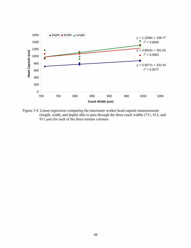
48
y = 0.5577x + 322.43r2 = 0.9277
y = 1.2248x + 108.77r2 = 0.6506
y = 0.8915x + 351.53r2 = 0.5564
0
200
400
600
800
1000
1200
1400
1600
700 750 800 850 900 950 1000 1050
Crack Width (um)
Hea
d Ca
psul
e (u
m)
Depth Width Length
Figure 3-4. Linear regression comparing the maximum worker head capsule measurements
(length, width, and depth) able to pass through the three crack widths (711, 813, and 911 µm) for each of the three termite colonies.
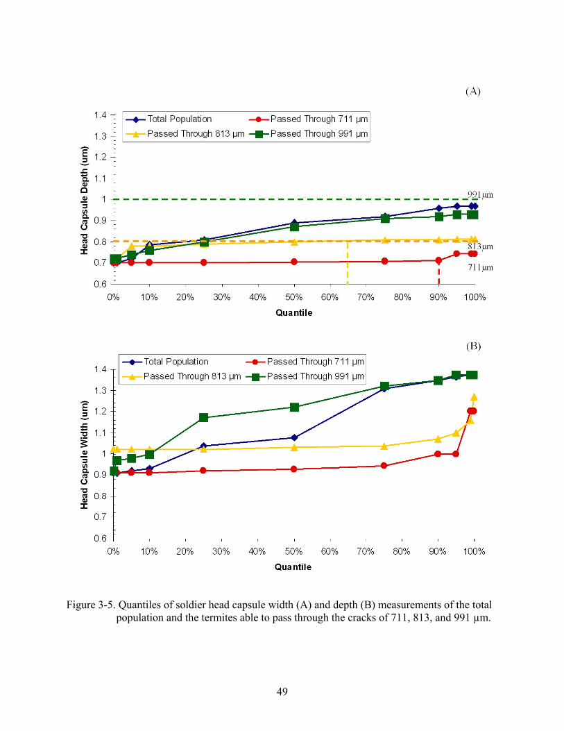
49
Figure 3-5. Quantiles of soldier head capsule width (A) and depth (B) measurements of the total
population and the termites able to pass through the cracks of 711, 813, and 991 µm.

50
Figure 3-6. Quantiles of worker head capsule width (A) and depth (B) measurements of the total
population and the termites able to pass through the cracks of 711, 813, and 991 µm.
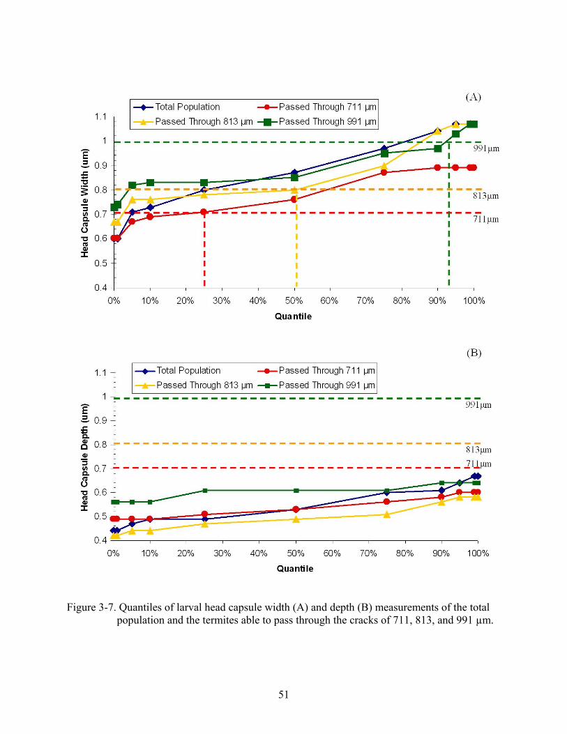
51
Figure 3-7. Quantiles of larval head capsule width (A) and depth (B) measurements of the total
population and the termites able to pass through the cracks of 711, 813, and 991 µm.

52
CHAPTER 4 METHODS TO PREVENT PENETRATION OF CONCRETE-PIPE INTERFACES BY THE
EASTERN SUBTERRANEAN TERMITE
Introduction
Subterranean termites in North America typically nest in the ground and enter structures
either around the foundation perimeter or next to pipe penetrations. Termites cannot penetrate
concrete, so the foundation can act as a physical barrier to entry into the structure (Lentz et al.
1997) provided there are no cracks or other hidden termite entry points due to construction
design. It has been shown that termite tunneling is influenced by guidelines and passageways
(Pitts-Singer and Forschler 2000, Swoboda and Miller 2004). Therefore pipes beneath structures
may guide termite movement into buildings through plumbing penetrations in the foundation.
Pipes for plumbing and utilities are placed during the initial construction phase before the
slab is poured. An average slab-on-grade foundation has multiple pipe penetrations using several
pipes typically composed of metal (copper) or plastics (chlorinated polyvinyl chloride [CPVC]
and polyvinyl chloride [PVC]). Copper pipes are required by the current international building
code (IBC 2006) to have pipe sleeving on pipe sections that penetrate and contact the slab to
protect the pipe from corrosion and abrasion. Protective pipe sleeving is recommended by
building codes (FBC 2004, IBC 2006) and the CPVC pipe manufacturer (Lubrizol 2007). No
pipe sleeving is required or recommended for PVC pipe (IBC 2006).
The most common termiticide treatment for termite prevention at new construction is
chemical treatment of the soil using a repellent or non-repellent termiticide. Chemical
termiticide treatment around critical areas, such as plumbing, must extend 30 cm (1ft) below the
sand-slab interface and is applied at a higher volume than elsewhere in the structure. Repellent
termiticides can act as a chemical barrier (Tamashiro et al. 1987, Jones 1990, Smith and Rust
1990, Su and Scheffrahn 1990a, Grace 1991) provided there are no gaps in the treatment.

53
Lubrizol (2007) recommends that CPVC pipe sleeving extends at least 30 cm (1ft) below the
slab, the same depth as the required termiticide treatment around critical areas. This could result
in the soil around the bottom opening of the pipe sleeve containing relatively little or no
termiticide. Termites foraging along the pipes could then enter the structure through the pipe
sleeve, protected from any contact with the termiticide treatment. Termite infestations
originating at gaps around pipe penetrations through the concrete slabs may go undetected long
enough to result in significant damage to structures (AS 1995).
In addition to liquid termiticides, the US pest control industry currently has used two
commercial products that may potentially prevent termite entry through gaps around pipe
penetrations through slabs: Termimesh™ (Termimesh Australia Pty Ltd , Australia) and
Impasse™ Termite Blocker (Syngenta Crop Protection, Inc., Greensboro, NC). Termimesh™, a
stainless steel mesh with an aperture of 660 by 450 µm, has been documented to prevent termites
from entering through gaps in slab over which the mesh is attached (ABSAC 1992, Lentz and
Runko 1994). Impasse™ Termite Blocker, herein referred to as termite blocker, contains the
repellent termiticide lamda-cyhalothrin sealed between two thick layers of construction-grade
polymer, which prevents termites from chewing through the polymer (Su et al. 2004). Both
products must be secured around pipes or other conduit before the concrete slab is poured,
sealing the products into the foundation of the structure.
The purpose of this research was to evaluate the efficacy of physical and chemical products
and their installation methods for preventing termite access along pipe penetrations to the upper
surface of a concrete slab. The factors evaluated with typical plumbing were pipe sleeve length
and composition in combination with soil termiticide treatment and termite blocker.

54
Materials and Methods
Termites
Eastern subterranean termites, R. flavipes, were field collected using traps from several
locations in Gainesville, FL. A trap consisted of a 6-liter plastic bucket inserted below ground
with its lid accessible above the soil surface. Each bucket was filled with 2-3 moistened
corrugated cardboard rolls (15 cm long by 10 cm diam.; Gainesville Paper Co., Gainesville, FL).
Termites accessed cardboard rolls through ~10 holes (4-cm diam.) on the sides and bottom of
each bucket. Cardboard rolls containing termites were collected and returned to the lab.
Termites were removed from the cardboard and reared at room temperature (~23°C) in plastic
boxes (27 by 19 by 9.5 cm) with moistened cardboard for ≤2 wk before inclusion in the
experimental arenas. The laboratory maintained termites used in the experiment were gently
shaken from clean cardboard, weighed, and then inspected to confirm that there was
approximately a 1:100 soldier:worker ratio.
Pipe Sleeve Experiment
Pipe Sleeve Treatments
Dry builders sand (0.04 m3) was treated with TalstarOne™ (Bifenthrin, FMC Corporation,
Philadelphia, PA) diluted 8.7 ml in 5.6 L tap water to obtain the maximum label concentration of
0.12% a.i. The termiticide-treated sand was mixed in a cement mixer for 15 minutes, spread
over a plastic tarp, and air-dried to allow termiticide to bind to the sand. A new termiticide
mixture was prepared for each replicate. Untreated control sand was prepared in the same
manner as the termiticide sand mixtures but using only tap water. All sand was remoistened
(10% moisture wt:wt) immediately prior to use in the experiment.
Five treatment configurations of CPVC pipes (Flowguard®, Noveon, Inc., Cleveland, OH)
(60 cm long, 2.2 cm OD [3/4 in.]) were evaluated. Pipes were installed without pipe sleeving or

55
wrapped in two lengths, 20 cm or 50 cm, of sleeving consisting of either foam (FosterKing,
Thermwell Product Co., Inc., Mahwah, NJ) or polyethylene (Great Bay Productions, Inc. St.
Petersburg, FL).
Pipe Sleeve Experimental Arena
The experimental arena (Figure 4-1) was constructed by capping a PVC tube (61 cm long x
15.3 cm diam.) and adding 5 cm of dry builders sand. A CPVC pipe (60 cm long, 2.2 cm OD
[3/4 in.]), with or without pipe sleeving, was embedded in the sand. Concrete (Quickrete®
concrete mix #1101, Atlanta, GA) poured on top of the sand around the CPVC pipe created a
slab 15.3 cm diam. by 10 cm height. After the concrete dried, the PVC tube arena was inverted
and the sand was removed. The CPVC pipe penetrated through the center of the slab, extending
5 cm above slab and 45 cm below the slab. Pipe sleeves were trimmed to be flush with the upper
slab surface and to extend either 20 cm or 50 cm below the slab. Temporary wax paper
wrappings were used to prevent contamination of non-treated arena surfaces and the space
between the CPVC pipe and sleeve when treated sand was added. The wax paper was wrapped
inside the lower 15 cm of the PVC tube distal to the concrete and around the bottom of the
CPVC pipe and sleeves. Moistened sand treated with termiticide or water only was added to the
PVC tube and extended ~30 cm below the concrete slab. This resulted in short pipe sleeves (20
cm) being contained within the termiticide treatment and the long pipe sleeves (50 cm) extending
below the termiticide treatment. About 15 cm of untreated moistened builders sand was then
added to fill the PVC tube. A pre-weighed, corrugated cardboard (8 cm2) was placed on the
moistened untreated sand. Termites (10 g, ~2500 workers and 25 soldiers), were introduced on
top of the cardboard. After termites tunneled into the sand, the bottom end of the tube was
capped. Another pre-weighed corrugated cardboard disk (15.25 cm diam.) was placed around
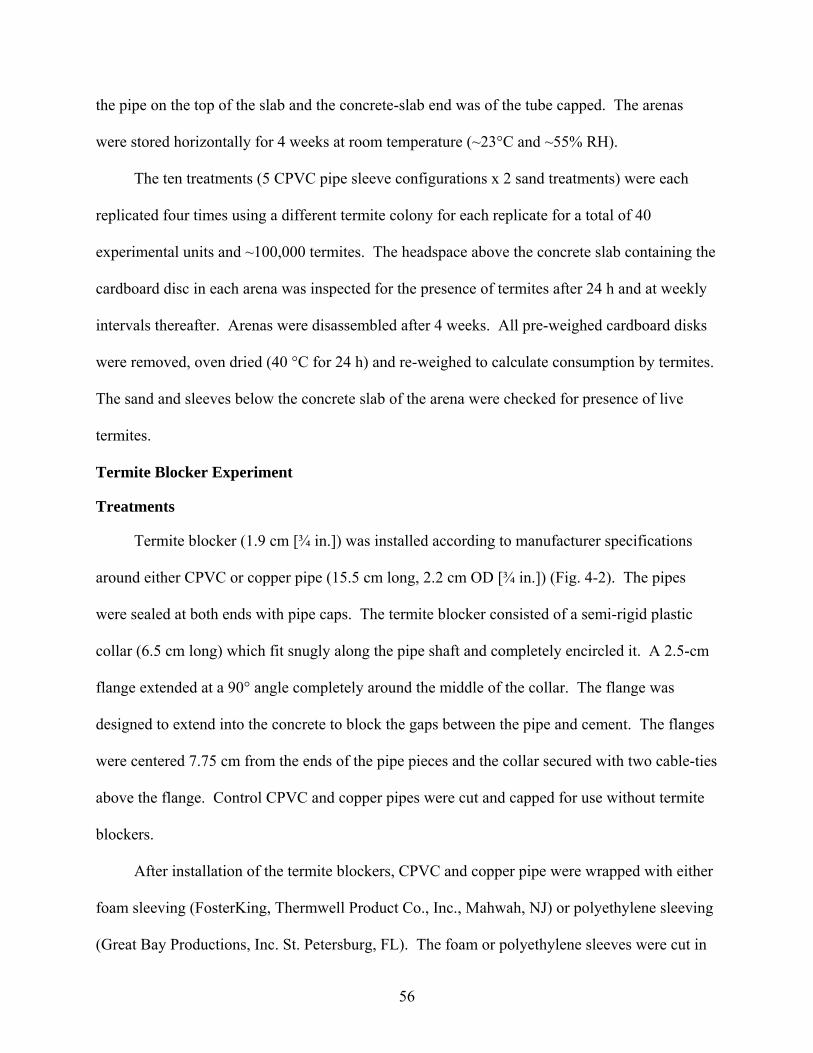
56
the pipe on the top of the slab and the concrete-slab end was of the tube capped. The arenas
were stored horizontally for 4 weeks at room temperature (~23°C and ~55% RH).
The ten treatments (5 CPVC pipe sleeve configurations x 2 sand treatments) were each
replicated four times using a different termite colony for each replicate for a total of 40
experimental units and ~100,000 termites. The headspace above the concrete slab containing the
cardboard disc in each arena was inspected for the presence of termites after 24 h and at weekly
intervals thereafter. Arenas were disassembled after 4 weeks. All pre-weighed cardboard disks
were removed, oven dried (40 °C for 24 h) and re-weighed to calculate consumption by termites.
The sand and sleeves below the concrete slab of the arena were checked for presence of live
termites.
Termite Blocker Experiment
Treatments
Termite blocker (1.9 cm [¾ in.]) was installed according to manufacturer specifications
around either CPVC or copper pipe (15.5 cm long, 2.2 cm OD [¾ in.]) (Fig. 4-2). The pipes
were sealed at both ends with pipe caps. The termite blocker consisted of a semi-rigid plastic
collar (6.5 cm long) which fit snugly along the pipe shaft and completely encircled it. A 2.5-cm
flange extended at a 90° angle completely around the middle of the collar. The flange was
designed to extend into the concrete to block the gaps between the pipe and cement. The flanges
were centered 7.75 cm from the ends of the pipe pieces and the collar secured with two cable-ties
above the flange. Control CPVC and copper pipes were cut and capped for use without termite
blockers.
After installation of the termite blockers, CPVC and copper pipe were wrapped with either
foam sleeving (FosterKing, Thermwell Product Co., Inc., Mahwah, NJ) or polyethylene sleeving
(Great Bay Productions, Inc. St. Petersburg, FL). The foam or polyethylene sleeves were cut in
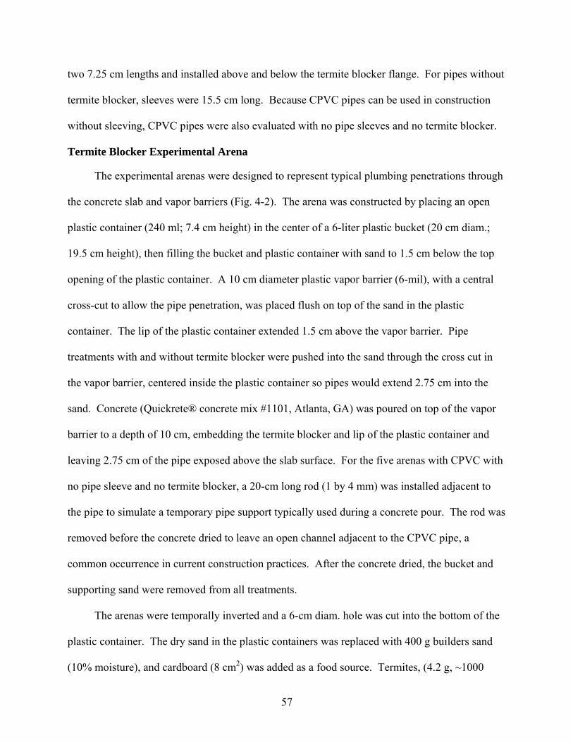
57
two 7.25 cm lengths and installed above and below the termite blocker flange. For pipes without
termite blocker, sleeves were 15.5 cm long. Because CPVC pipes can be used in construction
without sleeving, CPVC pipes were also evaluated with no pipe sleeves and no termite blocker.
Termite Blocker Experimental Arena
The experimental arenas were designed to represent typical plumbing penetrations through
the concrete slab and vapor barriers (Fig. 4-2). The arena was constructed by placing an open
plastic container (240 ml; 7.4 cm height) in the center of a 6-liter plastic bucket (20 cm diam.;
19.5 cm height), then filling the bucket and plastic container with sand to 1.5 cm below the top
opening of the plastic container. A 10 cm diameter plastic vapor barrier (6-mil), with a central
cross-cut to allow the pipe penetration, was placed flush on top of the sand in the plastic
container. The lip of the plastic container extended 1.5 cm above the vapor barrier. Pipe
treatments with and without termite blocker were pushed into the sand through the cross cut in
the vapor barrier, centered inside the plastic container so pipes would extend 2.75 cm into the
sand. Concrete (Quickrete® concrete mix #1101, Atlanta, GA) was poured on top of the vapor
barrier to a depth of 10 cm, embedding the termite blocker and lip of the plastic container and
leaving 2.75 cm of the pipe exposed above the slab surface. For the five arenas with CPVC with
no pipe sleeve and no termite blocker, a 20-cm long rod (1 by 4 mm) was installed adjacent to
the pipe to simulate a temporary pipe support typically used during a concrete pour. The rod was
removed before the concrete dried to leave an open channel adjacent to the CPVC pipe, a
common occurrence in current construction practices. After the concrete dried, the bucket and
supporting sand were removed from all treatments.
The arenas were temporally inverted and a 6-cm diam. hole was cut into the bottom of the
plastic container. The dry sand in the plastic containers was replaced with 400 g builders sand
(10% moisture), and cardboard (8 cm2) was added as a food source. Termites, (4.2 g, ~1000

58
workers:10 soldiers) collected from one location in Gainesville, FL, were introduced onto the
cardboard. The hole was plugged and the arena was inverted. Wood blocks were placed under
the concrete slabs extending outside the plastic container to stabilize the arenas in the upright
position on the laboratory counter. Pipe sleeves were trimmed flush to the top of the concrete
slab. An additional food source of a moistened, pre-weighed corrugated cardboard disk (10 cm
diam.) was placed around the pipe on top of the concrete slab. To prevent moisture loss, a
plastic container (240 ml; 7.4 cm height) was inverted over the pipe and cardboard on the
concrete surface. The cardboard was moistened as needed throughout the experiment period.
The nine treatments (2 pipes x 2 pipe sleeves x 2 blocker + CPVC pipe only) were
replicated five times. Arenas were checked daily for eight weeks to document the date that any
termites were present above the slab. The arenas were disassembled after 8 wk. The pre-
weighed cardboard disks on the concrete surface were removed, oven dried (40°C for 24 h), and
re-weighed to calculate consumption by termites.
Data Analysis
In pipe sleeve length experiments, the number of experimental arenas where termites were
able to access the moist cardboard above the concrete, and cardboard consumption (g),
calculated from the dry cardboard weights before and after the assays, were analyzed with one-
way analysis of variance (ANOVA) and were separated with Student-Newman Keuls (SNK), (P
= 0.05; SAS 2001). In addition, a t-test compared termite slab penetration and cardboard
consumption in treated and untreated sand for each combination of pipe sleeve length and
composition (SAS 2001).
For the termite blocker experiment, the day of first appearance of termites above the slab
and cardboard consumption were also analyzed with one-way analysis of variance (ANOVA)
and were separated with Student-Newman Keuls (SNK), (P = 0.05; SAS 2001). A t-test

59
compared arenas having termite blocker and pipe treatments to arenas without termite blocker
and the same pipe treatments (SAS 2001).
Results
Pipe Sleeve Experiment
On the bottom of the arena, termites consumed an average of 2 g (~83%) of the cardboard
during the 28-day experimental period. There was no significant difference in consumption of
the cardboard placed on the bottom in arenas treated with the repellent termiticide compared the
untreated to arenas (F = 2.29; df = 1; P = 0.1385), or with different sleeve composition (no
sleeve, foam, and polyethylene) and sleeve length (short [20 cm] and long [50 cm]) (F = 0.84; df
= 4; P = 0.5093). Termites in the bottom of both termiticide treated and untreated arenas were
active and healthy at the end of the 28-day experimental period.
The concrete poured in the experiments did not show any visible evidence of shrinkage or
cracking around the pipe treatment penetrations on top of or below the slab after arenas were
disassembled for inspection. The pipe treatments with sleeves were easily pulled from the
concrete slab, however, the pipes without a sleeve were snugly fixed to the concrete.
At no time did the termites gain access the top of the concrete slab in arenas without pipe
sleeves in either the termiticide-treated or untreated arenas. The sleeveless CPVC pipe was
completely imbedded in the concrete slab with no gaps for termites to access the surface of the
concrete. The termites were not able to access the surface of the concrete therefore they did not
consume the cardboard on the surface (Table 4-1).
When termites were able to access the top of the concrete through the annular space
between the pipe sleeve (foam and polyethylene) and pipe, they deposited frass, chewed
cardboard, and sand on this surface and the adjacent PVC wall (Figs. 4-3A, B). Arenas in which
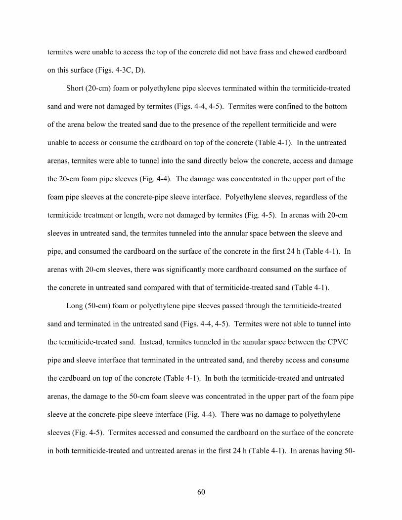
60
termites were unable to access the top of the concrete did not have frass and chewed cardboard
on this surface (Figs. 4-3C, D).
Short (20-cm) foam or polyethylene pipe sleeves terminated within the termiticide-treated
sand and were not damaged by termites (Figs. 4-4, 4-5). Termites were confined to the bottom
of the arena below the treated sand due to the presence of the repellent termiticide and were
unable to access or consume the cardboard on top of the concrete (Table 4-1). In the untreated
arenas, termites were able to tunnel into the sand directly below the concrete, access and damage
the 20-cm foam pipe sleeves (Fig. 4-4). The damage was concentrated in the upper part of the
foam pipe sleeves at the concrete-pipe sleeve interface. Polyethylene sleeves, regardless of the
termiticide treatment or length, were not damaged by termites (Fig. 4-5). In arenas with 20-cm
sleeves in untreated sand, the termites tunneled into the annular space between the sleeve and
pipe, and consumed the cardboard on the surface of the concrete in the first 24 h (Table 4-1). In
arenas with 20-cm sleeves, there was significantly more cardboard consumed on the surface of
the concrete in untreated sand compared with that of termiticide-treated sand (Table 4-1).
Long (50-cm) foam or polyethylene pipe sleeves passed through the termiticide-treated
sand and terminated in the untreated sand (Figs. 4-4, 4-5). Termites were not able to tunnel into
the termiticide-treated sand. Instead, termites tunneled in the annular space between the CPVC
pipe and sleeve interface that terminated in the untreated sand, and thereby access and consume
the cardboard on top of the concrete (Table 4-1). In both the termiticide-treated and untreated
arenas, the damage to the 50-cm foam sleeve was concentrated in the upper part of the foam pipe
sleeve at the concrete-pipe sleeve interface (Fig. 4-4). There was no damage to polyethylene
sleeves (Fig. 4-5). Termites accessed and consumed the cardboard on the surface of the concrete
in both termiticide-treated and untreated arenas in the first 24 h (Table 4-1). In arenas having 50-

61
cm sleeves, the consumption of cardboard on the surface of the concrete was not significantly
different in termiticide-treated and untreated arenas (Table 4-1).
Termite Blocker Experiment
When termites were released into the moistened sand, they began to tunnel and explore the
arenas. The cardboard squares at the bottom of the arena were not weighed; however, at the end
of the experiment, part of this cardboard was consumed and the termites appeared to be healthy.
Termites reached the top of the concrete slab of the arenas on average between 2.2 and 3.6
days in all treatments having no termite blocker, whereas no termites reached the top of the slab
in any termite blocker treatment (F = 15.93; df = 8; P <0.0001). The difference in cardboard
disk consumption in pipe sleeve treatments with and without termite blocker was significant (T-
test; T = 18.97; df = 38; P < 0.0001). Termites consumed an average of 1.3 ± 0.1 g cardboard in
all experimental arenas without termite blocker compared to no consumption of the cardboard
disk in the termite blocker treatments (Fig. 4-6). There was no significant difference in
cardboard disk consumed between treatments without termite blocker (F = 0.5; df = 4; P =
0.7382).
Termites caused observable damage to the foam insulation, tunneling into the foam pipe
sleeves and removing foam. Termites also moved sand and fecal matter in their tunnels in the
foam pipe sleeves. In arenas with foam pipe sleeves and termite blocker, damage to the foam
pipe sleeve only occurred below the termite blocker flange. The termite blocker flange
prevented passage of termites; therefore, termites were unable to damage the pipe sleeve above
the flange. In arenas that had foam pipe sleeve treatments and no termite blocker, the foam pipe
sleeve was extensively damaged by termite tunneling. Termites caused no damage to the
polyethylene pipe sleeve material.

62
In arenas that had termite blocker, the flange imbedded in the concrete and the secure
collar around the pipe prevented termites from accessing the slab surface. However, when the
termite blocker was not installed, the termites constructed trails and shelter tubes in the annular
space between the pipes and the sleeves that extended from the sand to the surface of the
concrete. This tunneling behavior of lining the walls with sand and fecal matter was also
observed in arenas with no termite blocker and no pipe sleeves, which had a hole created in the
concrete with a rod.
The concrete poured in the experiments did not show any visible evidence of shrinkage or
cracking around the pipe treatment penetrations on the top of the concrete slab. As in the
previous experiment, the pipe treatments with sleeves could easily be pulled from the concrete
slab, but the pipe treatments with termite blocker or without a sleeve were snugly fixed to the
concrete.
Discussion
The pipe sleeve assays demonstrated that pipe sleeve length had a significant effect on
termite movement through sand treated with a repellent termiticide and subsequent consumption
of cardboard on the surface of the concrete. However, pipe sleeve composition and pipe type
had no significant effect. Bifenthrin, a repellent termiticide, was effective in preventing termite
passage through the slab, provided the pipe sleeve did not extend below the treated sand. If the
pipe sleeve extended below the treated sand, the termiticide treatment was bypassed by the
termites. This indicates that both foam and polyethylene sleeves are relatively impervious to
termiticide, providing a protected route for termites to tunnel through and effectively avoid
termiticide-treated sand.
Su et al. (1990a and 1993b) and Gahlhoff and Koehler (2001) found that subterranean
termites were unable to tunnel through sand treated with bifenthrin in laboratory tube tests.

63
Powell (2000) determined that termites were able to detect sand treated with repellent
termiticides and avoided the treated zone and access a food source through gaps in termiticide
treatment in the sand. In our study, termites were also able to avoid the termiticide-treated sand
and utilized the pipe as a guideline and the pipe sleeve as protection from the termiticide-treated
sand. The protected environment within the pipe sleeve gave termites access to the surface when
the pipe sleeve extended below the termiticide-treated sand.
Critical areas within a structure that are hidden from termite inspections include any pipe
penetrations through a slab with pipe sleeving that may extend below termiticide-treated sand.
Our study identified two commonly used pipe sleeves (foam and polyethylene) that allowed
termite access to the surface of the slab when the pipe sleeves extended beyond the termiticide-
treated sand. When the pipe sleeves terminated within the termiticide-treated sand, the termites
were unable to access the surface of the slab.
Termites are known to follow natural guidelines in the soil, tunneling along objects like
tree roots in search of food (Pitts-Singer and Forschler 2000, Campora and Grace 2001). This
behavior may easily be adapted to pipes and pipe sleeves, so a longer pipe sleeve penetrating into
untreated sand can give termites a guide to follow into the structure.
The termite blocker prevented termites from accessing the surface of the slab in all arenas
in our experiments. When installed properly, termite blocker is embedded into the concrete and
secured to the pipes, like Termimesh, to prevent termite access. In a field study, it was
determined that Heterotermes spp., a small species of subterranean termite, was able to squeeze
through the screen openings of Termimesh™ (Lentz and Runko 1994). In contrast, Impasse™
Termite Blocker is a solid 2-layer membrane impregnated with lamda-cyhalothrin which is
completely impenetrable to termites of any size (Su et al. 2004). Our study also showed that the

64
presence of termite blocker, regardless of pipe and sleeve type, prevents slab penetration by
termites and subsequent above-slab consumption of cardboard.
Protective measures are important for preventing termite entry into structures via pipe slab
penetrations. A properly installed pipe sleeve that does not extend below the termiticide-treated
sand or termite blocker embedded in the concrete around the pipe both provides reliable
protection. Current construction codes should be modified to require that pipe sleeves do not
extend more than 20-cm below the slab and must terminate in the termiticide-treated zone. This
would prevent termites tunneling inside sleeves to bypass the termiticide treatments. In addition,
termite blocker could be used as a beneficial supplemental treatment when sand surrounding
plumbing penetrations is not treated with a soil termiticide.

65
Table 4-1. Effect of pipe sleeve composition and length and termiticide treatment on Mean consumption (g) of cardboard (± SE) on top of the concrete slab by termites.
Sleeve Termiticide-treateda Untreatedb Composition Length c Termitesd Consumption (g) ± SE Termitesd Consumption (g) ± SE t df P -- no sleeve - 0.00 ± 0.00b - 0.00 ± 0.00b - 6 - foam short - 0.00 ± 0.00b + 2.54 ± 0.26a 9.60 6 < 0.0001 long + 2.40 ± 0.25a + 2.48 ± 0.27a 0.20 6 0.8462 polyethylene short - 0.00 ± 0.00b + 2.39 ± 0.41a 5.86 6 0.0011 long + 2.75 ± 0.21a + 2.58 ± 0.50a -0.27 6 0.7974 Consumption is in g. Means within a column followed by the same letter are not significantly different. (Student-Neuman-Keuls Means Separation, P = 0.05, SAS Institute 2001). A t-test compared data within a row. n = 4 replicates. a Termiticide-treated sand prepared with TalstarOne, SNK termiticide-treated; F = 91.11, df = 4, P = <0.0001, b Untreated sand prepared with tap water, , SNK untreated; F = 11.29, df = 4, P = 0.0002, c Short = 20 cm; long = 50 cm, d Termites able to access concrete surface.
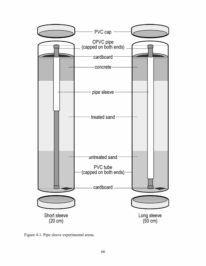
66
Figure 4-1. Pipe sleeve experimental arena.

67
Figure 4-2. Termite blocker experimental arena.

68
Figure 4-3. Top view of typical pipe sleeve experiment arenas at 28 d. A) and B) are representative arenas where termites reached the top of the concrete. C) and D) are representative arenas were termites could not access the top of the concrete.

69
Figure 4-4. Foam pipe sleeves exposed to eastern subterranean termites for 28 d in termiticide-
treated and untreated arenas. Arrows indicate location of termite surface damage.

70
Figure 4-5. Polyethylene pipe sleeves exposed to eastern subterranean termites for 28 d in termiticide-treated and untreated arenas.

71
1.4
1.211.3
1.35
1.48
0
0.5
1
1.5
Copper & Foam Copper &Polyethelene
CPVC & Foam CPVC &Polyethelene
CPVC & NoSleeve
Cons
umpt
ion
(g)
Figure 4-6. Mean cardboard consumption (g) (± SE) after 8 wk by termites in arenas without termite blocker around copper and CPVC pipes, with or without foam or polyethylene sleeves.

72
CHAPTER 5 DEVELOPMENT OF A METHOD TO EVALUATE THE EFFECTS OF EASTERN
SUBTERRANEAN TERMITE DAMAGE TO THE THERMAL PROPERTIES OF BUILDING CONSTRUCTION MATERIALS
Introduction
Reticulitermes flavipes (Kollar) is a species of subterranean termite well known in North
America for the damage it causes to homes and other buildings. The damage is most commonly
thought of in terms of weakening a structure, making infested areas prone to collapse (Harris
1965, Johnston et al. 1979). Water damage is also associated with these termites, as they bring
moisture from the soil into their galleries within the structure (Hickin 1971, Grube and Rudolph
1999b).
One aspect of damage that has been overlooked is the change in the thermal properties of a
structure after infestation by subterranean termites. This is a concern in any structure built in a
climate that varies from the comfortable human range of ca. 20-25oC. Materials damaged by
subterranean termites are typically filled with galleries or, in the case of wood, laminar spaces
where spring wood has been eaten away (Forschler 1999b). These spaces may facilitate the
transfer of heat through a material, compromising the material’s capacity for insulation. If
material in an exterior wall is compromised, it will cost more to maintain a comfortable
temperature range within the structure. In this way, termite damage can be even more costly than
is generally believed.
In most American homes, exterior walls of structures are often made up of cellulosic
materials, such as the structural lumber (e.g., 2x4) and siding material (e.g., 5-ply plywood).
These two building materials are the most common exterior wall components in use that termites
are capable of consuming. Another class of building material highly relevant to thermal transfer
is insulation (e.g., rigid foam board). While most types of insulation are composed of plastics or

73
fiberglass, and thus cannot constitute a food source for termites, the soft texture found in many
types of insulation makes them easy for the termites to tunnel through (Bultman et al. 1972
missing from ref cited; Hickin 1971, NPCA 1993). In fact, the physical qualities of insulation
materials confer an appreciable amount of internal temperature stability, making them an almost
ideal habitat for termites. While termites may not be able to effectively consume most types of
insulation, they can still tunnel into and cause significant damage to insulation (Guyette 1994,
Smith and Zungoli 1995ab, Ogg, 1997).
The first objective of this experiment was to determine the relative damage by
subterranean termites to each building material. The second objective was to determine
differences in the rate of heat transfer and, consequently, temperature change between damaged
and undamaged samples of each building material.
Materials and Methods
Termites.
Five colonies of R. flavipes, separated by more than 1.5 km in Gainesville, FL, were field
collected in 6-liter plastic buckets inserted below ground with their lids accessible above the soil
surface. Each bucket was filled with 2-3 moistened corrugated cardboard rolls (15 cm long by
10 cm diam.; Gainesville Paper Co., Gainesville, FL). Termites accessed cardboard rolls through
~10 holes (4-cm diam.) in the sides and bottom of each bucket. Cardboard rolls containing
termites were collected and returned to the lab in Ziploc bags (3.8-L). Termites were removed
from the cardboard by gently separating the corrugated cardboard and allowing the termites to
fall into a 20-L plastic bucket. The termites were then placed on moistened corrugated cardboard
and reared at room temperature (~23°C) in plastic boxes (27 by 19 by 9.5 cm) with moistened
cardboard for ≤1 wk before inclusion in experimental arenas. Worker termites of at least 3rd

74
instar were aspirated into groups of 300 workers with a 1% soldier population for use in the
experiments.
Termite Damage to Construction Materials.
Three building construction materials were tested: pine 2x4s, 5-ply plywood, and rigid
foam board insulation. The 2x4s were cut across the grain to a thickness of 1.27 cm [½ inch].
Five-ply plywood and rigid foam insulation had a thickness of 1.2 cm [15/32 inch] and 1.9 cm
[3/4 inch], respectively. Each material was cut into square samples (4 x 4 cm) for exposure to
termites. The building materials were oven-dried at 40°C for 24 h and pre-weighed.
Moistened sand (10% water content) was evenly distributed inside a 0.74 L plastic
container (GladWare®; Glad Products Co., Oakland, CA). A sample of building material was
placed on a linoleum square (7.5 x 7.5 cm) on the surface of the sand. The linoleum provided a
barrier between the moistened sand and the building material. Termites were placed on the
moistened sand next to the linoleum and the building material. Lids were placed on the
containers, which were stored in the laboratory at ~23°C. Control arenas containing no termites
were prepared in the same manner.
The arenas were opened 8 wk after setup. Sand and termites were brushed off the surface
of the building materials and galleries. Building materials were then oven dried at 40°C for 24 h
and re-weighed to calculate termite damage. A digital image of each building material sample
was taken to record the visible damage caused by termites.
An experimental unit was defined as a plastic arena with a building material, sand,
linoleum, and 300 termites. Each building material (n=3) was evaluated using five termite
colonies with five replications per colony. The experiment had an equal number of control units
with no termites, resulting in a total of 150 experimental units tested.

75
Thermal Imaging.
The cleaned and oven dried building materials were photographed using an infrared (IR)
thermal imaging camera (FlexCam®; Fluke Corporation. Everett, WA). A tripod held the
thermal camera in place ~53 cm above a building material. An enamel container filled with dry
sand (2000 g builders sand) was placed on a hot plate and heated to 52ºC. The building materials
were tightly fitted to a pre-cut hole in rigid foam insulation square (10 x 10 cm) to minimize the
edge effect of heat radiating from the sand and hot plate. The building material, with the rigid
foam insulation surrounding it, was placed on the heated builders sand and thermal images were
taken at 0.5, 5, 10, and 15 min. During initial testing, the surface temperature reached
equilibrium for the samples during the 15 minutes period. The digital file associated with the
image included a thermal map of surface temperatures for the building material and a record of
the minimum, maximum, and average surface temperatures.
Data Analysis.
Percent damage from pre- and post-exposure weights of each sample of building material
was calculated, arcsine square root transformed, analyzed by one-way analysis of variance, and
means separated with SNK (P = 0.05; SAS Institute 2003). The initial temperature and the
maximum temperature reached during 15 min of heating for each building material was
recorded, and the mean temperature increase for the upper surface of the building material was
calculated. Significant differences in temperature for damaged and undamaged building
materials were determined with Student’s t-test (P = 0.01). The percentage increase in
temperature of a damaged sample in relation to the temperature of the same material not
damaged by termites was calculated.

76
Results
All three building construction materials were damaged by termites. Termites tunneled
into the insulation, removed the plastic, and caused significantly more damage, based on weight
loss, by tunneling in the insulation than by consuming either the wooden 2x4 or plywood
samples (Table 5-1). Plywood samples had significantly less damage than did the other building
materials.
2x4s.
The rings of lighter, spring wood and darker, summer wood were obvious in the visible
spectrum images (Fig. 5-1A). However, the rings were not noticeable in the thermal images
(Fig. 5-1C) indicating no noticeable difference in heat transfer between spring and summer
wood. The thermal images of undamaged 2x4 samples showed uniform heat transfer through the
wood at 0.5, 5, 10, and 15 min with the average surface temperature increasing only 0.5°C, from
23.9 to 24.4°C in the representative sample (Fig. 5-1C). After 15 min of heating, the undamaged
2x4 sample had a narrow range of temperatures (23.8 to 25.2°C) across the surface.
Termites ate a mean of 6.7% of each exposed 2x4 sample, causing characteristic damage in
the form of distinct lamellar tunnels excavated in the annular rings of the spring wood (Table 5-
1)(Fig. 5-1A). The thermal images of damaged 2x4 samples showed a greater overall heat
transfer compared with undamaged samples. There were distinct localized hot spots in the
images of the damaged 2x4s, where heat passed through more rapidly, that coincided with the
location of termite tunnels (Fig. 5-1B). After 15 min of heating, the representative damaged 2x4
sample had a wide range of surface temperatures (24.5 to 30.6°C), typical of the samples tested.

77
The mean temperature for all 2x4 samples was ~24°C at 0.5 min (Table 5-1). After 15 min
exposure, the average maximum surface temperature reached was 35% greater and significantly
more for termite damaged samples (31.0°C) compared to undamaged samples (28.8°C).
Plywood.
Samples of plywood showed fairly wide bands of spring and summer wood in the upper
layer, indicating a fairly oblique, longitudinal cut across the wood rings (Fig. 5-2A). Thermal
images of the undamaged samples showed almost uniform heat transfer, indicating no noticeable
difference in heat transfer for spring and summer wood areas of the plywood samples The
images showed little rise in temperature through 15 min of heating from 23.4 to 23.8°C in the
representative sample (Fig.5-2C), indicating plywood is a good insulating material. After 15 min
of heating, the undamaged representative plywood sample had a narrow range of temperatures
(23.3 to 25.2°C) across the surface.
Termites ate a mean of ~3% of each plywood sample (Table 5-1) (Fig. 5-2A). Rather than
excavating tunnels in spring wood as seen in the 2x4 sample (Fig. 5-1A), the termites tunneled
between plywood layers and consumed portions of the spring wood bands in each layer. The
thermal images of damaged plywood showed a greater overall heat transfer compared with
undamaged samples. The damage was demarcated by increased heat transfer and localized hot
spots in the thermal images (Fig. 5-2B). After 15 min of heating, the representative damaged
plywood sample had a wider range of temperatures (24.0 to 27.2°C) across the surface compared
to that of the undamaged sample.
For all the plywood samples, the mean temperature at 0.5 min was ~24°C (Table 5-1).
After 15 min of heating, the average maximum temperature was 25.7°C for undamaged plywood

78
and 27.5°C for termite damaged plywood. The increase in temperature for termite damaged
plywood was 74% greater and significantly more than that for undamaged plywood.
Rigid Foam Board Insulation.
Undamaged samples of rigid foam board insulation were very homogenous in appearance.
The insulation material of foam was covered by a radiant barrier composed of kraft paper
covered by a thin layer of aluminum. The undamaged sample of rigid foam insulation showed
low heat transfer and temperatures were very uniform across the entire surface, as observed in
the representative sample (Figure 5-3C). The thermal images of the representative undamaged
insulation sample showed an average surface temperature increase of only 0.4°C, from 23.4 to
23.8°C, after 15 min of heating, which was typical of samples tested.
Termite-damaged rigid foam insulation was riddled with extensive termite tunnels (Fig. 5-
3A), lined with soil and fecal material. The tunnels were more extensive than those seen in the
2x4 or plywood samples, most likely due to the soft nature of the insulation. The radiant barrier
had been largely eaten away, exposing the scarified, pitted foam. The thermal pictures of
damaged insulation samples showed a greater degree of temperature variability across the
surface of the insulation. The hotspots coincided with areas where termites had tunneled and
removed the insulation material (Fig. 5-3B). After 15 min of heating, the representative
damaged rigid foam insulation had a wide range of surface temperatures (24.2 to 30.0°C)
Heat transfer in damaged rigid foam insulation samples was greatly increased within the
extensive tunnel system (Table 5-1). For all the insulation samples, the mean temperature was
~23°C at 0.5 min. After 15 min of heating, the average maximum surface temperature was
27.4°C for undamaged samples and 28.7°C for damaged samples. The temperature increase was
~27% greater and significantly more for damaged insulation compared to undamaged insulation.
79
Discussion
All building materials tested were damaged by termites. There was very little correlation
between the percentage damage (% weight loss) of the building material and the percentage
increase in surface temperature caused by termite damage. It appeared that intrinsic thermal
properties of the construction material and configuration of termite tunneling were important in
determining the increase of thermal conductivity in relation of weight loss. Plywood samples
had the lowest percentage damage caused by termites and the greatest percentage increase in
surface temperature of damaged versus undamaged samples. The temperature increase in
damaged and undamaged plywood was the lowest of all the materials tested. This indicates that
of the undamaged materials tested, plywood was the most resistant to heat flow through it;
however, once eaten by termites, plywood was the most thermally damaged. This may be due to
the laminar structure of the plywood. Termites tunneled with the grain and between the layers of
plywood; however, some tunnels cut through the plywood layers allowing heat to flow through
the material. Consequently, the impact of termite tunneling through the layers was more
thermally significant than expected by the amount of wood damage.
Not surprisingly, rigid foam insulation was the second-most heat resistant material tested
in its undamaged state. Nonetheless, rigid foam had greatest weight loss of all the building
materials and the termite damage created a network of tunnels allowing heat transfer. Termites
tunneled throughout the rigid foam board, leaving multiple routes of rapid heat transfer between
surfaces of the sample.
The significantly greater temperature increase seen in 2x4 materials in comparison to
plywood was due to the cross-sectional nature of 2x4 samples. Plywood had wood fibers mostly
perpendicular to the direction of heat flow; whereas the 2x4 cross-sections had the wood fibers
mostly parallel to the direction of heat transfer assayed. Termites mainly tunneled along the

80
fibers and within the softer spring wood. These tunnels penetrated the sample allowing heat to
flow unobstructed through the sample. As a result, small termite wood damage of only 6-7%
was responsible for 35% greater increase in temperature in damaged samples compared to
undamaged samples.
With the increasing cost of energy, houses are being built to be more energy efficient using
foam insulation as well as wooden components. The impact of termites on the thermal properties
of these building materials has been virtually overlooked. Our research documented that termites
can significantly negatively impact the thermal properties of building construction materials
designed to be energy efficient. Our research demonstrates the importance of termite control for
home energy conservation.

81
Table 5-1. Percent damage and surface temperature increase for building materials heated for 15-min. Damaged materials were exposed to eastern subterranean termites (n=300) for 8 wk.
Material Damaged/ undamaged
% damage Initial temp Mean highest surface temp
Temp increasea
% temp increaseb
2x4 Undamaged - 24.2 ± 0.25 28.8 ± 0.12 4.5 ± 0.24 - Damaged 16.7 ± 0.75b 24.9 ± 0.24 31.0 ± 0.15* 6.1 ± 0.28* 34.8 Plywood Undamaged - 24.1 ± 0.23 25.7 ± 0.15 1.6 ± 0.20 - Damaged 13.1 ± 0.33c 24.8 ± 0.24 27.5 ± 0.11* 2.7 ± 0.29* 74.0 Insulation Undamaged - 23.4 ± 0.04 27.4 ± 0.08 4.0 ± 0.10 - Damaged 12.1 ± 1.10a 23.6 ± 0.10 28.7 ± 0.14* 5.1 ± 0.19* 27.1 * significant difference between damaged and undamaged (P = 0.01, Students t-test). a Mean temperature increase at the upper surface of the building material (4 x 4 cm) when lower surface was exposed to hot plate at 52°C for 15 min, b % temperature increase = ((damaged [temp increase] – undamaged [temp increase])/undamaged [temp increase]).
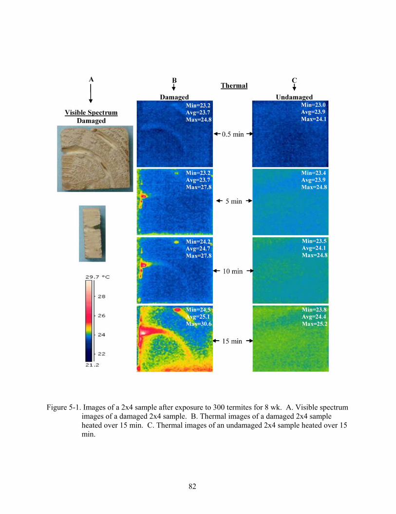
82
Figure 5-1. Images of a 2x4 sample after exposure to 300 termites for 8 wk. A. Visible spectrum
images of a damaged 2x4 sample. B. Thermal images of a damaged 2x4 sample heated over 15 min. C. Thermal images of an undamaged 2x4 sample heated over 15 min.

83
Figure 5-2. Images of a plywood sample after exposure to 300 termites for 8 wk. A. Visible spectrum images of damaged plywood samples. B. Thermal images of a damaged plywood sample heated over 15 min. C. Thermal images of an undamaged plywood sample heated over 15 min.

84
Figure 5-3. Images of a rigid foam insulation sample after exposure to 300 termites for 8 wk. A. Visible spectrum images of a damaged rigid foam insulation sample. B. Thermal images of a damaged rigid foam insulation sample heated over 15 min. C. Thermal images of an undamaged rigid foam insulation sample heated over 15 min.
85
CHAPTER 6 EFFECTS OF EASTERN SUBTERRANEAN TERMITE DAMAGE ON THE THERMAL
PROPERTIES OF COMMON BUILDING MATERIALS
Introduction
Reticulitermes flavipes (Kollar) is a species of subterranean termite well known in North
America for the damage it causes to homes and other buildings. The damage is most commonly
thought of in terms of weakening the materials of the structure, making potentially costly repairs
and renovations necessary. Water damage can also result from termite infestation. Termites, R.
santanensis De Feytaud, use their labial glands to move water into structures they infest to
maintain humidity and temperature in their gallery system, increasing the moisture content of the
building construction materials (Grube and Rudolph 1999ab).
One aspect of termite damage that is often overlooked is the change in the thermal
properties of a structure. This is a concern in any structure built in a climate that varies from the
comfortable human range of ca. 20-25oC (ASHRAE 2005). Solid materials damaged by
subterranean termites are typically filled with galleries that may facilitate the transfer of heat
through an object, compromising the material’s capacity for insulation. If an exterior wall of a
structure is compromised by termites, it may cost more to maintain a comfortable temperature
range within the structure. Therefore, termite damage to the thermal conductivity of a building
can be more costly than previously known and precede damage that compromises the structural
integrity or appearance of a building.
Exterior walls of structures are made up of structural lumber, siding materials, insulation,
and other internal components. Typical structural lumber is 2x4 or 2x6 cut from either Southern
yellow pine or Douglas fir trees, depending on the region. Common siding materials of plywood
(5 ply) or T1-11 siding (T1-11) are constructed from uniform layers or veneers of wood. The
uniform layers cut from logs are stacked so that the wood fibers of each layer are perpendicular

86
to each other, compressed and bonded together with glue. Another common siding material is
oriented strand board (OSB), formed by layering fragments of wood (2.5 by 15 cm) in specific
orientations. The surface of the OSB is rough with wood fragments positioned unevenly across
each other. The rectangular wooden fragments are compressed and bonded together with wax
and resin adhesives. The five types of building materials referenced above are common exterior
wall components composed of wood that termites are capable of consuming
Another class of building material important in thermal transfer is insulation. While most
types of insulation are created from synthetic materials and cannot constitute a food source for
termites, the soft texture found in many types of insulation makes it easy for the termites to
tunnel through (NPCA 1993). In fact, the physical qualities of insulation materials confer
internal temperature stability, making make them a suitable habitat for termites. Even though
termites may not be able to effectively digest most types of insulation, they can still severely
damage the product (Guyette1994, Smith and Zungoli 1995ab, Ogg 1997).
Energy efficiency codes for building construction require structures to meet minimum
insulation prescriptive standards. The United Stated is divided into eight climate zone (Briggs et
al. 2002). Exterior wood frame walls are required to have an R-value that ranges from 13 to 25,
depending on the climate zone in which the structure is build (IECC 2006). Each component
that comprises the building envelope has distinct physical properties which include an assigned
R-value. The building envelope consisting of a typical exterior wall has many components,
including interior paint, plasterboard, insulation, wood studs, exterior sheathing, vapor barrier,
exterior cladding, and exterior paint. The R-values of all these components are added together to
derive an R-value for the completed wall.

87
The first objective of this experiment was to determine termite survivorship on seven
building materials, providing some indication of each material’s suitability as a diet for termites.
The second objective was to determine the relative damage of each of the seven building
materials by subterranean termites. The final objective was to determine differences in the rate
of heat transfer between damaged and sound samples of each building material.
Materials and Methods
Termites
Five colonies of R. flavipes in Gainesville, FL, each separated by more than 1.5 km, were
field collected in 6-liter plastic buckets inserted below ground with their lids accessible above the
soil surface. Each bucket was filled with 2-3 moistened corrugated cardboard rolls (15 cm long
by 10 cm diam.; Gainesville Paper Co., Gainesville, FL). Termites accessed cardboard rolls
through ~10 holes (4-cm diam.) in the sides and bottom of each bucket. Cardboard rolls
containing termites were collected and returned to the lab in Ziploc® bags (3.8-L). Termites
were removed from the cardboard by gently separating the corrugated cardboard and allowed the
termites to fall into a 20-L plastic bucket. The termites were then placed on moistened
corrugated cardboard and maintained at room temperature (~23°C) in plastic boxes (27 by 19 by
9.5 cm) with moistened cardboard for ≤1 wk before inclusion in experimental arenas. Prior to
the test, worker termites of at least 3rd instar were randomly aspirated into groups of 300 workers
with a 1% soldier population.
Test Arena
The test arenas used to evaluate damage of wood and insulation materials consisted of a
sand base with linoleum on the surface on which a building material sample was placed. Seven
building construction materials were evaluated; 2x4, 2x6, oriented stand board (OSB), T1-11
88
plywood (T1-11), 5-ply plywood (5-ply), extruded polystyrene (EXP), and polyisocyanurate
insulation (ISO).
Builders sand was oven-dried at ~177°C for 24 h, sifted through a 1.18 mm mesh soil sieve
to remove debris, and moistened by mixing 50 ml of distilled water in 500 g sand. Moistened
sand was evenly distributed into a 0.74 L plastic container (GladWare®; Glad Products Co.,
Oakland, CA). A linoleum square (56 cm2) was placed on the surface of the moistened sand.
The linoleum provided a barrier between the moistened sand and the building materials. The
building materials dimensions were cut to the following sizes. The 2x4 and 2x6 materials were
purchased in 2.4 m [8 foot] lengths and were cut across the grain to a thickness of 1.27 cm [½
inch]. Because the nominal thickness of the two materials is fixed, the material had the
following dimensions 3.7 x 4.4 cm (~16.3 cm2). The remaining building materials were
purchased in sheets 1.2 by 2.4 m [4 by 8 feet] at a local building supply store and were cut into
squares 4 x 4 cm (16 cm2). Sample thickness varied by building material; OSB was 1.2 cm
[15/32 inch] thick, 5-ply plywood 1.8 cm [23/32 inch], T1-11 plywood 1.5 cm [19/32 inch], EXP
1.27 cm [1/2 inch] and ISO 1.9 cm [3/4 inch]. The building materials were oven-dried at 40°C
for 24 h and weighed.
The termites were placed on the moistened sand next to the linoleum and the building
materials. Lids were placed on the plastic arenas, which were stored in the laboratory at ~23°C.
Control arenas containing no termites were prepared in the same manner. The arenas were
opened eight wk after setup and live termites were counted. The pre-weighed building materials
were then brushed off, oven dried at 40°C for 24 h and re-weighed to calculate termite damage.
Digital images of the building materials were taken to record visible damage caused by termites.

89
An experimental unit was defined as a plastic arena containing sand, linoleum, a building
material and 300 termites. Each building material (n=7) was evaluated using five termite
colonies with five replications per colony. The experiment had an equal number of control units
with no termites, resulting in a total of 350 units tested.
Thermal Imaging Setup
All of the cleaned and oven dried building materials were photographed using a thermal
imaging camera (FlexCam®; Fluke Corporation. Everett, WA). A tripod held the thermal
camera in place ~53 cm above a building material. An enamel container filled with dry sand
(2000 g builders sand) was placed on a hot plate and heated to 52ºC. A square hole (~16 cm2)
was cut into rigid board insulation (10 by 10 cm) minimize the edge effect of heat radiating from
the sand and hot plate. The building material imbedded in the rigid board insulation was placed
on the heated builders sand and a thermal image was taken after 0.5, 5, 10, and 15 min.
Data Analysis
All analyses were conducted using SAS (SAS 2001). Mean termite survivorship was
calculated and converted to percent survivorship. Percent survivorship was arcsine square root
transformed and analyzed using one-way analysis of variance (ANOVA) with material as the
main effect and was separated with Student-Newman Keuls (SNK), (P = 0.05; SAS 2001).
Damage (g of material lost) was calculated for each material tested and analyzed using
one-way analysis of variance (ANOVA) with material as the main effect and was separated with
Student-Newman Keuls (SNK), (P = 0.05; SAS 2001). Damage for each material was converted
to percent damage, arcsine square root transformed, and analyzed using one-way analysis of
variance (ANOVA) with material as the main effect and were separated with Student-Newman
Keuls (SNK), (P = 0.05; SAS 2001).
90
A heat transfer index was derived from Fourier’s Law in one dimension (Healy and Flynn
2002) and calculated for each sample using the following equation:
HTI = (k)(t)(A)(ΔT)/L
where: HTI = heat transfer index, k = thermal conductivity (W/m * oC), t = time (min), A =
area (m2) for the corresponding control after 5 min reaction, ΔT = the change in temperature (oC),
and L = thickness (m).
Heat transfer indices (HTIs) were calculated for damaged and undamaged samples of each
material. Percent increase in HTI from undamaged to damaged samples was calculated for each
material and analyzed using one-way analysis of variance (ANOVA) with material as the main
effect and were separated with Student-Newman Keuls (SNK), (P = 0.05; SAS 2001). HTIs for
damaged and undamaged samples were compared for each material using a two-tailed t-test (α =
0.05; SAS 2001).
Surface temperatures for damaged and undamaged samples of each material at 0.5, 5, 10,
and 15 min were plotted and subjected to natural logarithmic regression. The coefficients of the
natural log (ln) for each equation were compared between damaged and undamaged samples for
each material. The 95% confidence limits (CL) were calculated and non-overlap of the CL
determined significant differences in slopes.
Results
All seven building construction materials evaluated were damaged by termites. Termite
damage of solid wood and wood products was characteristic in that the damage was mostly to the
soft spring wood and followed the grain. The insulation, which had no nutritional value to
termites, was extensively excavated. Termites damaged EXP by creating long tunnels under the
clear plastic barrier which were randomly oriented throughout the sample. In contrast, damage

91
to the ISO was concentrated at the surface where termites pitted and scarified the material under
the craft paper, which they consumed.
Structural Lumber
Undamaged samples of the 2x4 and 2x6 building material had rings of lighter spring wood
and darker summer wood that were obvious in the visible spectrum (Figs. 6-2A, 6-4A,
respectively). However, the rings were absent in the thermal images of the undamaged 2x4 and
2x6 samples (Figs. 6-2B, 6-4B, respectively) indicating no noticeable difference in heat transfer
by spring and summer woods. In addition, the thermal image of undamaged samples showed
uniform heat transfer through the wood after 15 min of heating. The representative undamaged
2x4 and 2x6 samples had a narrow range of temperatures (< 3oC) across the surface.
The survivorship of termites in the 2x4 and 2x6 samples was >83% after 8 wk (Table 6-1).
During that time, termites consumed significantly more 2x6 (0.33 g) than 2x4 (0.25 g; Table 6-
1). Damage in the 2x4 samples took the form of distinct lamellar tunnels excavated in the wood
annular rings (Fig. 6-2C). Damage in the 2x6s similar to the 2x4s, but tunnels were excavated
within the wider rings of less dense spring wood and the galleries extended the full thickness of
the sample (Fig. 6-4C). A thermal image of a representative damaged 2x4 sample (Fig. 6-2D)
and 2x6 sample (Fig. 6-4D) showed higher maximum temperatures by nearly 4°C in damaged
wood due to greater overall heat transfer compared to that in undamaged wood. There were
distinct hot spots in the images of the damaged samples that coincided with the location of
termite tunnels, indicating that these tunnels allowed more rapid heat transfer than the
surrounding wood. After 15 min of heating, the damaged 2x4 and 2x6 samples had a wider
range of surface temperatures in the representative samples than in undamaged samples.
Southern yellow pine 2x4s have an assigned thermal conductivity value (k) of
approximately 0.12 W/m*oC (Table 6-1) which is an inherent physical property of this material.

92
Using the k-value of the material, the calculated heat transfer index (HTI) for undamaged 2x4
samples was 1.063 (Fig. 6-1). This indicated that 2x4 was the most thermally conductive of the
undamaged materials. The HTI for termite damaged 2x4 samples was significantly greater and
30% higher than for undamaged samples, indicating that termite damage increases heat transfer
through damaged samples.
The HTI for undamaged 2x6 samples was 0.926, indicating it was the second most
thermally conductive of the undamaged building materials (Fig. 6-1). The HTI for the termite
damaged 2x6s was significantly greater and ~51% higher than the HTI for undamaged samples,
indicating higher heat transfer through damaged samples. The percent HTI increase for damaged
2x6 samples was also significantly greater than that for damaged 2x4 samples (Table 6-1).
Differences in the mean surface temperatures of individual 2x4 and 2x6 samples steadily
increased through time (Figs. 6-3 and 6-5). Regression analysis of temperature and time (ln)
indicated that the rate of temperature increase for damaged samples were significantly greater
than the rate of temperature increase for undamaged samples for 2x4 and 2x6 substrates.
Wood Based Siding
Representative undamaged OSB samples had thin overlapping wood fragments that were
generally long and narrow and were obvious in the visible spectrum image (Fig. 6-6A). The
pattern of wood fragments was slightly noticeable in the thermal image of the undamaged OSB
sample after 15 min of heating (Fig. 6-6B), indicating a slight difference in heat transfer between
the fragments of wood based on color difference (green and yellow). The representative
undamaged OSB sample had a narrow range of temperatures across the surface, ranging from
30.9 - 32.9oC.
Like structural lumber, undamaged samples of T1-11 (Fig. 6-8A) and 5-ply (Fig. 6-10A)
showed wide bands of spring and summer wood in the visible image, which were not visible in

93
the thermal image (Figs. 6-8B and 6-10B, respectively). The lack of thermal variation in the
undamaged T1-11 may be partially attributed to the perpendicular layering of the material. The
thermal images of undamaged T1-11 and 5-ply representative samples showed uniform heat
transfer through the wood after 15 min of heating, with temperatures across the surfaces varying
less than 1.5oC.
Termite survivorship after feeding 8 wk was significantly lower (~59%) on T1-11 samples
than that of OSB (~67%), 5-ply (~79%), and the other materials tested (Table 6-1). Although
survival of termites feeding on 5-ply was good, this substrate had significantly lower wood
consumption and damage than any other substrate, including T1-11 and OSB. Wood
consumption and damage were not significantly different between T1-11 and OSB.
Visual damage to wood sidings varied based on wood fiber orientation. Damage in the T1-
11 and 5-ply samples was similar to that seen in structural lumber in that the termites tunneled
into the spring wood. Termites preferentially consumed bands of spring wood in T1-11 (Fig. 6-
8C) and 5-ply (Fig. 6-10C); however, the termite damage formed longitudinal pockets on the
surface rather than the rings seen in the structural lumber. There were distinct localized hot spots
in the thermal image of the damaged T1-11 (Fig. 6-8D) and 5-ply (Fig. 6-10D) coinciding with
the removal of the bands of spring wood, allowing heat to pass through more rapidly. The hot
spot across the top of the thermal image of the representative T1-11 was due to termite damage
of an interior layer not visible in the visible spectrum image.
In contrast, damage in the OSB took the form scarifying of the surface and short tunnels
and holes in spring wood, largely between the thin wood fragments, visible as dark breaks in the
surface (Fig. 6-6C). A thermal image of a representative damaged OSB sample (Fig. 6-6D)
showed distinct localized hot spots that coincided with the location of termite tunnels and

94
scarification of the wood fragments, again showing that termite damage allowed more rapid local
heat transfer.
After 15 min of heating, all the damaged wood siding samples had higher maximum
temperatures than undamaged samples, with OSB having the greatest difference between
damaged and undamaged samples (Fig. 6-6B, D). The maximum temperatures were associated
with termite damage. Damaged samples of T1-11 (Fig. 6-8D) and OSB (Fig. 6-6D) typically had
greater range in temperatures (>4.5°C) than did damaged samples of 5-ply (Fig. 6-10D). 5-ply
also had the least difference between maximum temperatures of damaged and undamaged
samples (Fig. 6-10 B, D).
The calculated HTI for undamaged OSB samples was 0.706, indicating it was the most
thermally conductive of the wood based siding materials tested (Fig. 6-1). There were no
significant differences in HTI between the damaged and undamaged OSB, although the HTI for
the damaged OSB was 12% higher than the HTI for undamaged OSB (Table 6-1).
In contrast, the calculated HTI’s for undamaged samples of 5-ply and T1-11 were 0.213
and 0.502, respectively, indicating these were the most thermally resistant wood-based materials
tested (Fig. 6-1). The HTI for termite damaged samples was significantly greater for undamaged
samples for both these sidings, indicating a higher rate of heat transfer through damaged samples
(Fig. 6-1). The HTI of damaged 5-ply samples was ~73% higher than undamaged samples, a
difference that was significantly greater those documented for all other materials tested (Table 6-
1).
Mean surface temperatures of individual samples steadily increased through time for OSB
(Fig. 6-7), T1-11 (Fig. 6-9) and 5-ply (Fig. 6-11). Regression analysis of temperature and time
(ln) indicated that the rate of temperature increase for damaged samples was not significantly
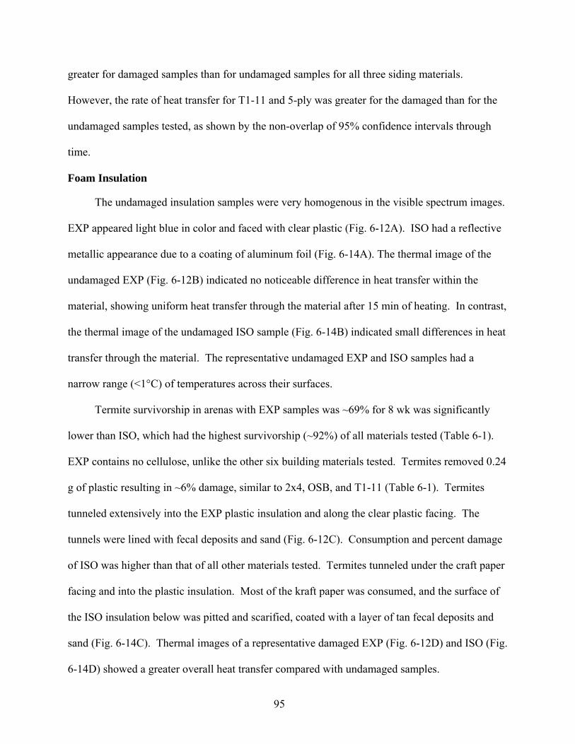
95
greater for damaged samples than for undamaged samples for all three siding materials.
However, the rate of heat transfer for T1-11 and 5-ply was greater for the damaged than for the
undamaged samples tested, as shown by the non-overlap of 95% confidence intervals through
time.
Foam Insulation
The undamaged insulation samples were very homogenous in the visible spectrum images.
EXP appeared light blue in color and faced with clear plastic (Fig. 6-12A). ISO had a reflective
metallic appearance due to a coating of aluminum foil (Fig. 6-14A). The thermal image of the
undamaged EXP (Fig. 6-12B) indicated no noticeable difference in heat transfer within the
material, showing uniform heat transfer through the material after 15 min of heating. In contrast,
the thermal image of the undamaged ISO sample (Fig. 6-14B) indicated small differences in heat
transfer through the material. The representative undamaged EXP and ISO samples had a
narrow range (<1°C) of temperatures across their surfaces.
Termite survivorship in arenas with EXP samples was ~69% for 8 wk was significantly
lower than ISO, which had the highest survivorship (~92%) of all materials tested (Table 6-1).
EXP contains no cellulose, unlike the other six building materials tested. Termites removed 0.24
g of plastic resulting in ~6% damage, similar to 2x4, OSB, and T1-11 (Table 6-1). Termites
tunneled extensively into the EXP plastic insulation and along the clear plastic facing. The
tunnels were lined with fecal deposits and sand (Fig. 6-12C). Consumption and percent damage
of ISO was higher than that of all other materials tested. Termites tunneled under the craft paper
facing and into the plastic insulation. Most of the kraft paper was consumed, and the surface of
the ISO insulation below was pitted and scarified, coated with a layer of tan fecal deposits and
sand (Fig. 6-14C). Thermal images of a representative damaged EXP (Fig. 6-12D) and ISO (Fig.
6-14D) showed a greater overall heat transfer compared with undamaged samples.

96
Approximately 20% of the thermal image was covered with localized hot spots in the damaged
EXP that coincided with the location of termite tunnels and removal of plastic. There were
several distinct localized hot spots in the image of the damaged ISO that coincided with the
location of termite tunnels and the removal of aluminum foil coated craft paper. Both the kraft
paper removal and the tunnels in the insulation below allowed heat to pass through the sample
more rapidly. The minimum temperatures for the damaged and undamaged samples were the
same for each foam type. The maximum temperature for damaged samples compared to
undamaged samples was ~6oC higher for EXP and ~10oC higher for ISO. Higher temperatures
were associated with termite damage.
The calculated HTIs for undamaged samples was 0.164 for EXP and 0.109 for ISO,
indicating these were the most thermally resistant of the tested materials (Fig. 6-1), which would
be expected for materials developed to insulate buildings. The HTIs for the termite damaged
EXP and ISO was significantly greater those for undamaged insulation, indicating a greater heat
transfer through damaged samples (Fig. 6-1). The HTI of damaged EXP samples was ~38%
higher than undamaged samples, and the % HTI increase was greater than that seen on ISO
(Table 6-1).
Mean surface temperatures of individual samples of EXP (Figure 6-13) and ISO (Fig. 6-
15) steadily increased through time. Regression analysis of temperature and time (ln) indicated
that the rate of temperature increase for damaged samples was significantly greater than for
undamaged samples for both EXP and ISO.
Discussion
The resin in manufactured wood products appeared to decrease termite survivorship. Our
study determined that termite survivorship was significantly lower on resin based, engineered
wood (OSB, T1-11, and 5 ply) than 2x4 and 2x6. OSB contains phenol-formaldehyde resin as a

97
bonding agent. Other researchers have documented that Formosan termites had substantial
mortality after consuming resinous building materials; ~55% mortality after 3 wk consuming
OSB (Ayrilmis et al. 2005) and 53% mortality after 5 wk consuming plywood (Tsunoda 2001).
Termites caused an intermediate percent damage to the OSB samples compared to other
building materials. The other sidings (T1-11 and 5-ply) compared to OSB had lower mean
percent damage. This difference may be due several reasons; the laminar structure of the T1-11
and 5-ply, laminations are typically cut from older trees that have denser wood or a different
resin from used in OSB used to adhere the laminations.
The wood materials that had a malleable consistency had the greatest termite damage. The
2x6 material had significantly higher percent damage than the 2x4 material, in spite of similar
composition and a lack of significant difference in mean termite survivorship. The difference in
damage was not due to wood species, since 2x4 and 2x6 samples were made from southern
yellow pine. However, 2x4 lumbers are typically cut from younger, faster-growing trees than
2x6 lumbers. One effect of this is that the 2x6 lumbers have wider layers of soft spring wood
bordered with denser summer wood. Because R. flavipes termites feed preferentially on less
dense wood (Behr et al. 1972) this difference between 2x4 and 2x6 densities could easily cause
significant differences in wood consumption, and resulting damage and heat transfer.
Structural lumber such as 2x4 and 2x6 must be strong, in both tension and compression, to
withstand structural loads. Damage due to notching and drilling may reduce structural integrity.
Notched wood should have a maximum depth of 25% of the width and bored holes should be no
larger than 40% in an exterior wall (Miller et al. 2004). In this study, the 2x4 and 2x6 samples
tested were not damaged by termites to this extent due to short duration of exposure and
relatively small number of termites.

98
The major component of the two insulation materials tested was plastic. EXP insulation
composed of plastic foam and a clear plastic barrier does not provide any nutritional value to
termites, so in the absence of suitable food source, termites began to starve in these trials. This
effect was not seen on ISO samples because this insulation was faced with a radiant barrier
composed of kraft paper covered with a thin layer of aluminum foil. The cellulose content of
this kraft paper provided adequate sustenance to significantly improve termite survivorship.
Termites extensively damaged the soft insulation materials. Su et al. (2003) described
insulation (molded bead-board) damaged by termites as having patches where the surface was
severely excavated and had several tunneling holes. Our study found that the damaged
insulation described by Su et al. (2003) was similar to the ISO; however, the damage to the EXP
took the form of a network of tunnels excavated under the clear plastic barrier. The ISO foam
insulation had significantly greater damage and percent damage than the EXP foam insulation.
In the ISO samples, termites stayed near to the food source (kraft paper), so most of the damage
to the underlying foam took the form of scarification rather than complete tunneling. The EXP
insulation had no kraft paper, and so the termites tunneled throughout the soft plastic material,
leaving multiple routes and extensive galleries.
The significantly greater heat transfer seen in 2x4 and 2x6 materials in comparison to
siding materials was due to the cross-sectional nature of the structural lumbers. Heat transfer
probably flowed more easily with the grain of the wood fibers in the 2x4 and 2x6 samples. The
siding materials were laminar or semi-laminar, with wood fibers mostly perpendicular to the
direction of heat transfer assayed. In contrast, the structural lumber cross-sections had the wood
fibers mostly parallel to the direction of heat transfer assayed.
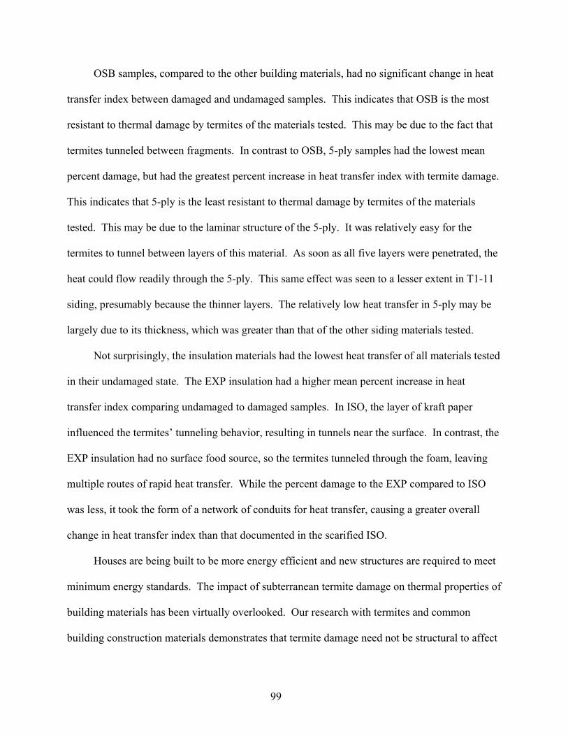
99
OSB samples, compared to the other building materials, had no significant change in heat
transfer index between damaged and undamaged samples. This indicates that OSB is the most
resistant to thermal damage by termites of the materials tested. This may be due to the fact that
termites tunneled between fragments. In contrast to OSB, 5-ply samples had the lowest mean
percent damage, but had the greatest percent increase in heat transfer index with termite damage.
This indicates that 5-ply is the least resistant to thermal damage by termites of the materials
tested. This may be due to the laminar structure of the 5-ply. It was relatively easy for the
termites to tunnel between layers of this material. As soon as all five layers were penetrated, the
heat could flow readily through the 5-ply. This same effect was seen to a lesser extent in T1-11
siding, presumably because the thinner layers. The relatively low heat transfer in 5-ply may be
largely due to its thickness, which was greater than that of the other siding materials tested.
Not surprisingly, the insulation materials had the lowest heat transfer of all materials tested
in their undamaged state. The EXP insulation had a higher mean percent increase in heat
transfer index comparing undamaged to damaged samples. In ISO, the layer of kraft paper
influenced the termites’ tunneling behavior, resulting in tunnels near the surface. In contrast, the
EXP insulation had no surface food source, so the termites tunneled through the foam, leaving
multiple routes of rapid heat transfer. While the percent damage to the EXP compared to ISO
was less, it took the form of a network of conduits for heat transfer, causing a greater overall
change in heat transfer index than that documented in the scarified ISO.
Houses are being built to be more energy efficient and new structures are required to meet
minimum energy standards. The impact of subterranean termite damage on thermal properties of
building materials has been virtually overlooked. Our research with termites and common
building construction materials demonstrates that termite damage need not be structural to affect

100
the thermal properties of the building materials. Our research demonstrates the importance of
termite control for home energy conservation and indicates further research is needed to identify
and develop building materials which resist termite damage and the minimize loss of thermal
properties if damage occurs.

101
Table 6-1. Mean ± SE percent termite survivorship, damage (g), percent damage, and percent increase in heat transfer index (HTI) between undamaged and building material damaged by subterranean termites (n=300) and after 8 wk.
Building material Material % survivorshipa Damage (g) % damage k-valueb % HTI c increase Structural lumber 2x4 83.64 ± 1.75bc 0.25 ± 0.03b 16.72 ± 0.75b 0.12 29.95 ± 2.80cd 2x6 88.65 ± 1.35ab 0.33 ± 0.03a 11.25 ± 1.16a 0.12 51.15 ± 8.19b Wood-based siding OSB 66.71 ± 3.65d 0.28± 0.03b 18.44 ± 0.99b 0.13 12.23 ± 1.51d T1-11 59.00 ± 2.83e 0.23 ± 0.03b 15.73 ± 0.61b 0.13 26.58 ± 8.45cd 5-ply 78.61 ± 3.08c 0.17 ± 0.03c 13.05 ± 0.33c 0.13 72.90 ± 8.49a Foam insulation EXP 68.88 ± 3.34d 0.24 ± 0.01b 15.71 ± 0.33b 0.03 37.51 ± 5.73bc ISO 92.45 ± 0.96a 0.35 ± 0.03a 12.07 ± 1.10a 0.02 20.96 ± 1.81cd
Means within a column followed by the same letter are not significantly different (Student-Neuman-Keuls Means Separation, P = 0.05, SAS Institute 2001), n = 25 replicates. a n = 300 termites per arena, b W/m * oC, (ASHRAE 2005, Miller et al. 1999, NIST 2000), c HTI = Heat transfer index.
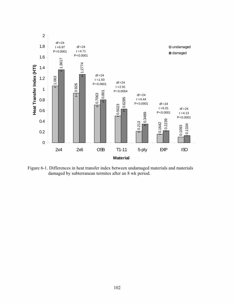
102
1.06
3
0.92
6
0.70
63
0.50
23
0.21
3
0.16
42
0.10
93
1.36
17
1.27
74
0.80
1
0.62
85
0.34
89
0.22
39
0.13
34
0
0.2
0.4
0.6
0.8
1
1.2
1.4
1.6
1.8
2
2x4 2x6 OSB T1-11 5-ply EXP ISO
Material
Hea
t Tra
nsfe
r Ind
ex (H
TI)
undamageddamaged
df = 24t = 6.97
P < 0.0001df = 24t = 4.71
P < 0.0001
df = 24t = 4.44
P < 0.0001
df = 24t = 2.91
P = 0.0054
df = 24t = 1.93
P = 0.0601
df = 24t = 5.01
P < 0.0001df = 24t = 4.13
P < 0.0001
Figure 6-1. Differences in heat transfer index between undamaged materials and materials
damaged by subterranean termites after an 8 wk period.

103
Figure 6-2. The 2x4 samples. Representative visible spectrum images (A, C) and thermal images
(B, D) of undamaged (A, B) and termite-damaged (C, D) 2x4 samples after being heated (52°C) for 15 min.
104
Figure 6-3. Natural log linear regression of 2x4 samples, termite damaged (red lines) and undamaged (blue lines), comparing temperature change (C°) recorded at ~0, 5, 10 and 15 m time intervals. Confidence intervals (95%) are represented by fine line around the regression lines and confidence limits (95%) of the slopes are given.

105
Figure 6-4. The 2x6 samples. Representative visible spectrum images (A, C) and thermal images
(B, D) of undamaged (A, B) and termite-damaged (C, D) 2x6 samples after being heated (52°C) for 15 min.

106
Figure 6-5. Natural log linear regression of 2x6 samples, termite damaged (red lines) and undamaged (blue lines), comparing temperature change (C°) recorded at ~0, 5, 10 and 15 m time intervals. Confidence intervals (95%) are represented by fine line around the regression lines and confidence limits (95%) of the slopes are given.

107
Figure 6-6. The OSB samples. Representative visible spectrum images (A, C) and thermal
images (B, D) of undamaged (A, B) and termite-damaged (C, D) OSB samples after being heated (52°C) for 15 min.

108
Figure 6-7. Natural log linear regression of OSB samples, termite damaged (red lines) and undamaged (blue lines) comparing temperature change (C°) recorded at ~0, 5, 10 and 15 m time intervals. Confidence intervals (95%) are represented by fine line around the regression lines and confidence limits (95%) of the slopes are given.
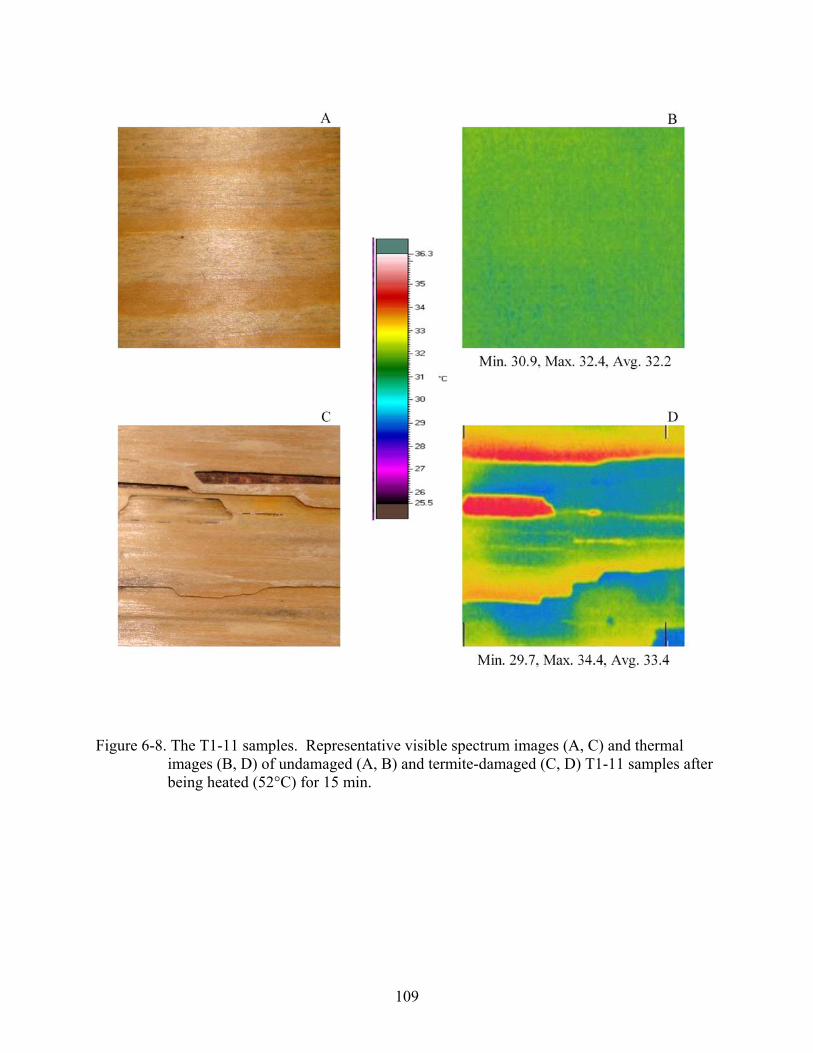
109
Figure 6-8. The T1-11 samples. Representative visible spectrum images (A, C) and thermal
images (B, D) of undamaged (A, B) and termite-damaged (C, D) T1-11 samples after being heated (52°C) for 15 min.
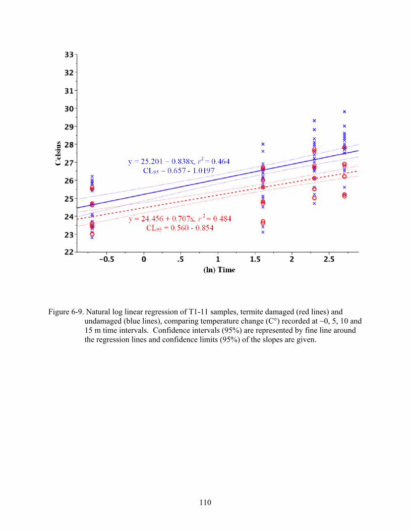
110
Figure 6-9. Natural log linear regression of T1-11 samples, termite damaged (red lines) and undamaged (blue lines), comparing temperature change (C°) recorded at ~0, 5, 10 and 15 m time intervals. Confidence intervals (95%) are represented by fine line around the regression lines and confidence limits (95%) of the slopes are given.

111
Figure 6-10. The 5-ply samples. Representative visible spectrum images (A, C) and thermal
images (B, D) of undamaged (A, B) and termite-damaged (C, D) 5-ply samples after being heated (52°C) for 15 min.

112
Figure 6-11. Natural log linear regression of 5-ply samples, termite damaged (red lines) and undamaged (blue lines), comparing temperature change (C°) recorded at ~0, 5, 10 and 15 m time intervals. Confidence intervals (95%) are represented by fine line around the regression lines and confidence limits (95%) of the slopes are given.

113
Figure 6-12. The EXP samples. Representative visible spectrum images (A, C) and thermal
images (B, D) of undamaged (A, B) and termite-damaged (C, D) EXP samples after being heated (52°C)for 15 min.
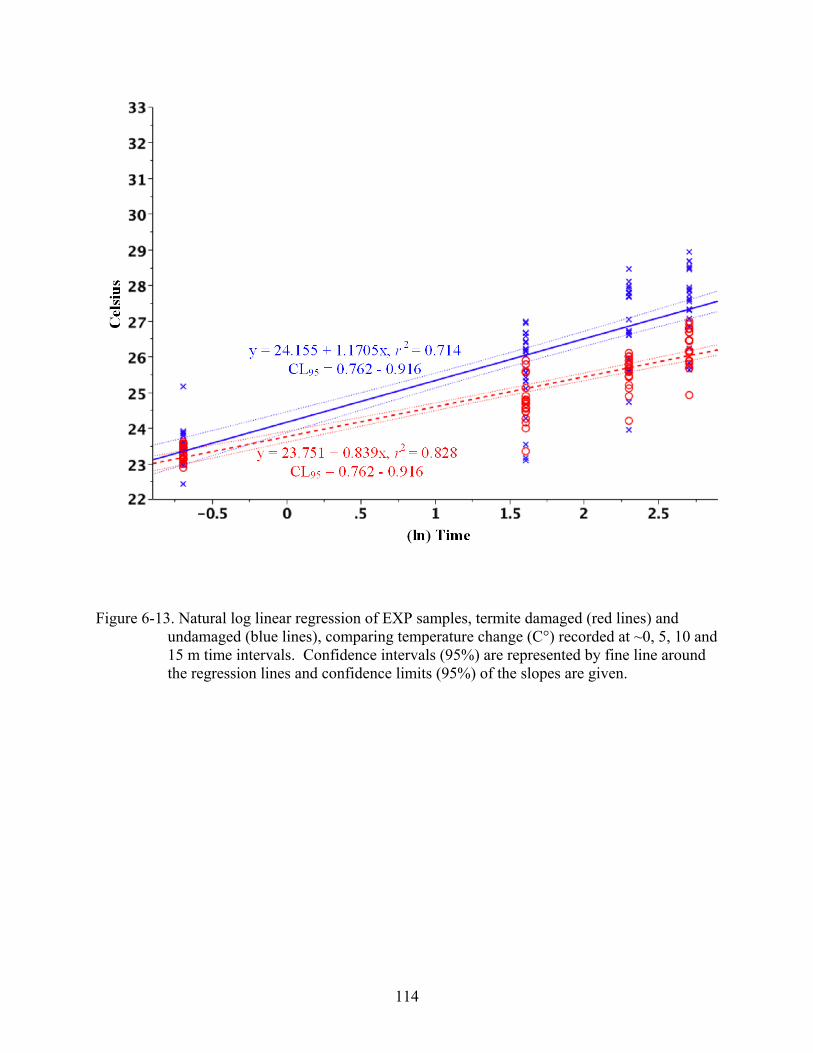
114
Figure 6-13. Natural log linear regression of EXP samples, termite damaged (red lines) and undamaged (blue lines), comparing temperature change (C°) recorded at ~0, 5, 10 and 15 m time intervals. Confidence intervals (95%) are represented by fine line around the regression lines and confidence limits (95%) of the slopes are given.
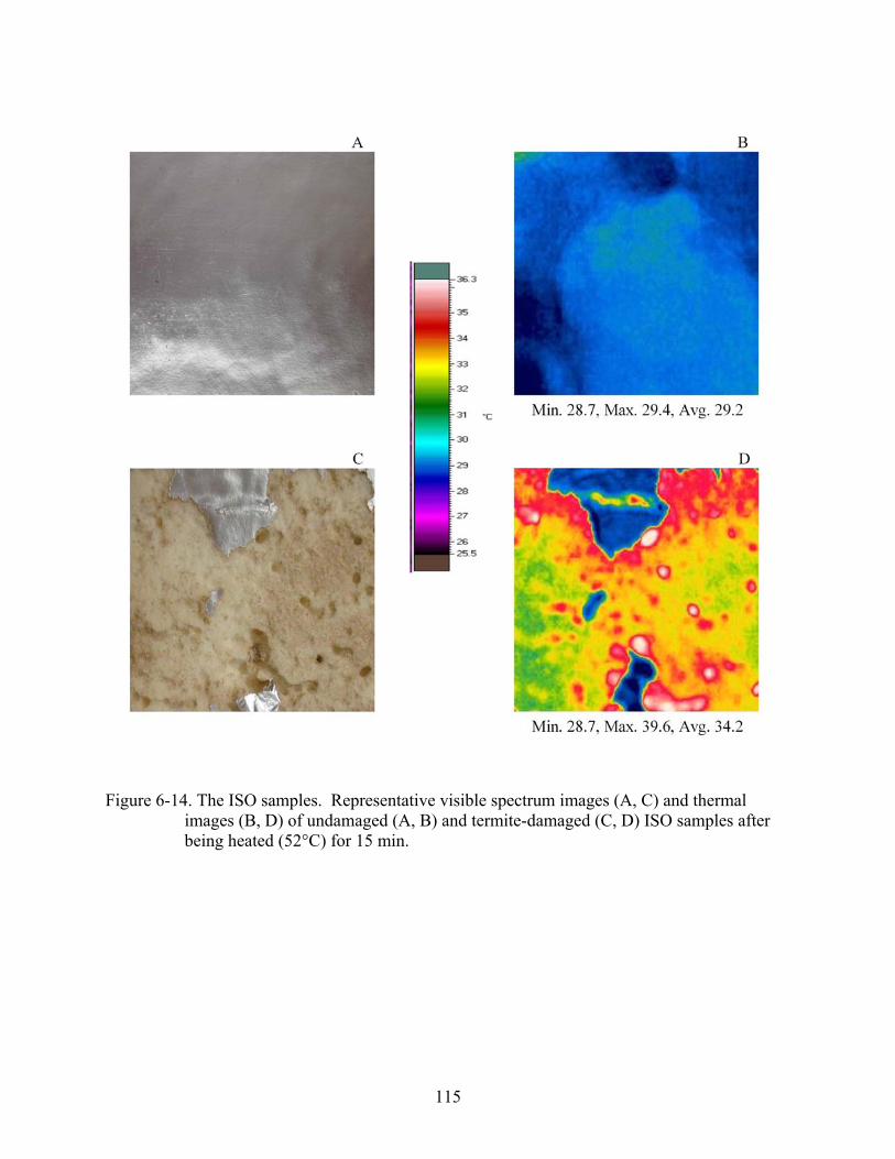
115
Figure 6-14. The ISO samples. Representative visible spectrum images (A, C) and thermal
images (B, D) of undamaged (A, B) and termite-damaged (C, D) ISO samples after being heated (52°C) for 15 min.
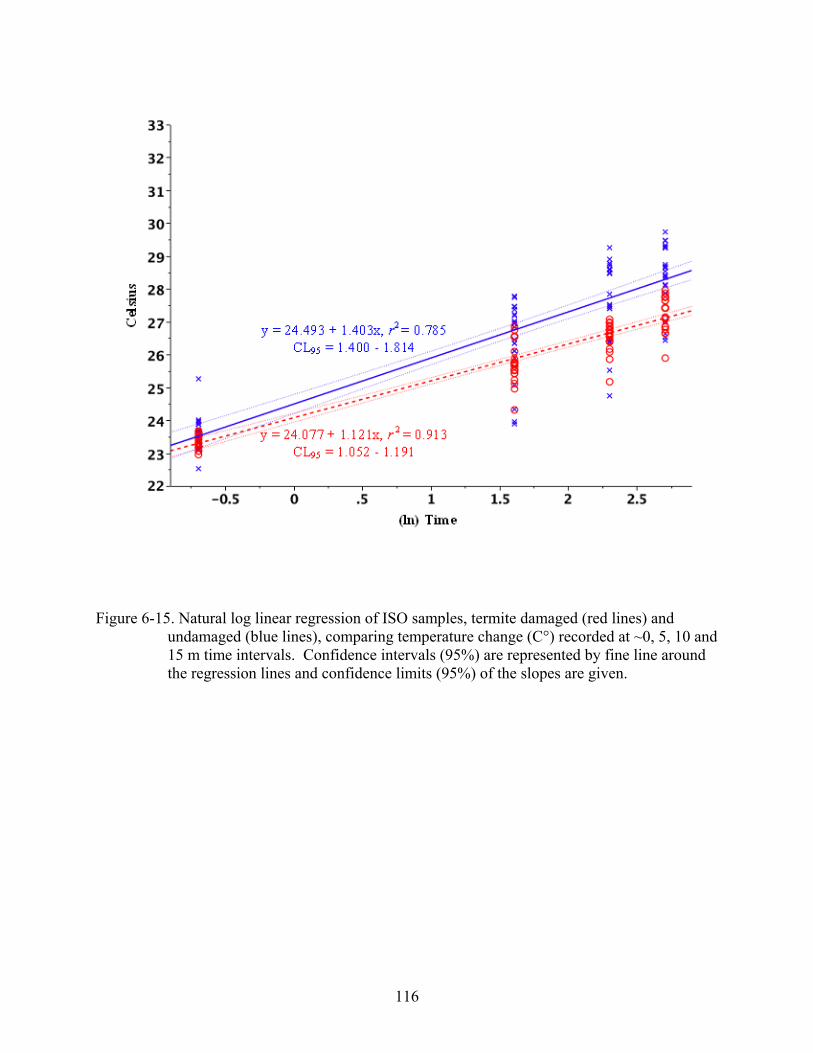
116
Figure 6-15. Natural log linear regression of ISO samples, termite damaged (red lines) and undamaged (blue lines), comparing temperature change (C°) recorded at ~0, 5, 10 and 15 m time intervals. Confidence intervals (95%) are represented by fine line around the regression lines and confidence limits (95%) of the slopes are given.

117
CHAPTER 7 CONCLUSION
Termite crack size assays showed a minimum crack width of ~0.7 mm is necessary for R.
flavipes worker termites to travel through a crack. Assays further showed that R. flavipes soldier
termites require a minimum crack width of ~1 mm to pass through a crack.
Pipe sleeve assays indicated that both foam and polyethylene pipe sleeves allowed termite
access through a concrete slab if the sleeves extend below the termiticide-treated sand.
However, termites were not able to access pipe sleeves that terminated within the termiticide-
treated sand. Based upon these findings, it is important that protective measures are taken to
prevent termite entry into structures via pipe and conduit slab penetrations. A properly installed
pipe sleeve that does not extend below the termiticide-treated sand appeared to provide reliable
protection. Care must be taken with soil treatment to ensure that it extends below the sleeve, if
present.
Termite blocker assays showed that the presence of Impasse™ Termite Blocker, with or
without sleeves or termiticide treatment, was sufficient to prevent slab penetration for at least 8
wk. Termite blocker properly installed and embedded in the concrete around the pipe should
provide reliable protection from termites.
A method was developed to determine heat transfer using a hot plate to heat termite
damaged and undamaged materials and document the surface temperature change through time
with a thermal camera. The building construction materials (2x4s, 5-ply plywood, and rigid
foam board insulation) were exposed to termites for 8 wk. Termites tunneled into and damaged
all the building materials. When 2x4s were heated the surface temperature (°C) was ~35%
higher in damaged compared to undamaged samples. Plywood damaged by termites was the

118
most thermally damaged with a temperature increase of 74% (damaged vs. undamaged samples)
and insulation had a temperature increase of ~27% (damaged vs. undamaged samples).
A heat transfer index was developed to compare heat transfer through termite damaged
building construction materials (2x4 and 2x6 pine lumber, 5 ply plywood, T1-11 siding, oriented
strandboard, extruded polystyrene, and polyisocyanurate insulation). Termite damaged materials
had higher heat transfer indices than undamaged materials The heat transfer index of damaged
2x4 and 2x6 lumber was 37% higher than damaged 5 ply plywood and T1-11 siding: therefore
the siding materials were more thermally resistant. As would be expected the insulation
materials had lower heat transfer index values than the wood materials. Termite damaged
polyisocyanurate was 68% more conductive than the damaged expanded polystyrene insulation.
In conclusion, the most likely routes for termite entry into structures are cracks and gaps in
the foundation wider than 0.7 mm and unprotected pipe sleeves extending below soil treatments.
The former of these routes can be remedied with adequate termiticide treatment below the slab.
The latter can be remedied with termite blocker installed at construction and/or pipe sleeves cut
short enough to not extend below termiticide-treated soil. If a structure is to be built in a hot or
cold climate with concerns about termite damage and thermal transfer, OSB is a logical choice
for wood-based siding while ISO foam is a preferable form of insulation. If all of these factors
are taken into consideration while building a structure, it will be far more difficult for
subterranean termites to invade, and the termites will cost the owner less money in increased
heating and/or air conditioning bills if they do enter the structure.
119
LIST OF REFERENCES
[ABSAC] Australian Building System Appraisal Council. 1992. Technical opinion 158 termi-mesh termite control system. Aust. Build. Syst. Appraisal Counc., East Melbourne Australia.
[ACI] American Concrete Institute. 2004. Control of cracking in concrete structures, ACI 224R-01, American Concrete Institute. Farmington Hills, MI.
Allen, E. 1999. Fundamentals of building construction, materials and methods. John Wiley &
Sons Inc. New York, NY. Anonymous. 1980. Design of wood frame: structures for performance. Nat. Forest Prod. Assoc.
No. 6. Washington, D.C. [AS] Australian Standard. 1995. Protection of buildings from subterranean termites. Part 1:
New buildings. In Australian standard AS 3660.1. Standards Australia, Homebush. [ASHRAE] American Society of Heating, Refrigerating, and Air-Conditioning Engineers.
2005. Thermal comfort. pp. 201-220. In ASHRAE handbook of fundamentals. ASHRAE Inc. Atlanta, GA.
Ayrilmis, N., S. N. Kartal, T. L. Laufenberg, J. E. Winandy, and R. H. White. 2005.
Physical and mechanical properties and fire, decay, and termite resistance of treated oriented strandboard. Forest Prod. J. 55: 74-81.
Banks, F. A. 1946. Species distinction in Reticulitermes (Isoptera: Rhinotermitidae).
Dissertation. University of Chicago. Department of Zoology. IL. Beal, R. H., J. K. Mauldin, and S. C. Jones. 1989. Subterranean termites, their prevention and
control in buildings. USDA Home Garden Bull., No. 64. Washington D.C. Behr, E. A., C. T. Behr, and L. F. Wilson. 1972. Influence of wood hardness of feeding by the
Eastern subterranean termite, Reticulitermes flavipes (Isoptera: Rhinotermitidae). Ann. Entomol. Soc. Amer. 65: 457-460.
Benboundjema, F. F. Meftah, and J.-M. Torrenti. 2005. Structural effects of drying
shrinkage. J. Eng. Mech. 131: 1195-1199. Booth, L. D., and W. M. Lee. 1985. Effects of polymer structure on K-factor aging of rigid
foam polyurethane foam. J. Cell. Plast. 21: 26-30. Briggs, R. S., R. G. Lucas, and Z. T. Taylor. 2002. Climate classification for building energy
codes and standards. (http://www.energycodes.gov/implement/pdfs/climate_paper_review_draft_rev.pdf).
Bueche, F. and D. L. Wallach. 1994. Technical Physics. John Wiley and Sons, Inc. New York.
120
Bultman, J. D., C. R. Southwell, and R. H. Beal. 1972. Termite resistance of polyvinyl chloride plastics in southern temperate and tropical environments. Final Report of Phase 1 – Effects with plasticizers and insecticides. Washington, DC: Naval Res. Lab. Rep. 7417.
Campbell, R. H., W. Harding, E. Misenhimer, L. P. Nicholson, and J. Sisk. 1976. Job
conditions affect cracking and strength of concrete in-place. ACI J. Proc. 73: 10–13. Campora, C. E., and J. K. Grace. 2001. Tunnel orientation and search pattern sequence of the
Formosan subterranean termite (Isoptera: Rhinotermitidae). J. Econ. Entomol. 94: 1193-1199.
Clement, J. L., M. Jequel, J. L. Leca, C. Lohou, and G. Burban. 1996. Elimination of
foraging populations of Reticulitermes santonensis in one street of Paris, France using hexaflumuron baits, pp. 640. In D. B. Wildey [ed.], Proceedings of the International Conference on Insect Pests in the Urban Environment. Edinburgh, UK.
Cornelius, M. L. 2003. Foraging behavior of Coptotermes formosanus and Reticulitermes
flavipes (Isoptera: Rhinotermitidae). Sociobiology 41: 105-11. Ebeling, W. 1975. Urban Entomology. University of California, Division of Agricultural
Services, Los Angeles, CA. Ebeling, W., and R. J. Pence. 1957. Relation of particle size to penetration of subterranean
termites through barriers of sand and cinders. J. Econ. Entomol. 59: 690-692. Eggleton, P. 2000. Global patterns of the diversity, pp. 25-51. In T. Abe, D. E. Bignell, and M.
Higashi [eds.], Termites: evolution, sociality, symbiosis, ecology. Kluwer Academic Pub. Dordrecht, The Netherlands.
Ettershank, G., J .A. Ettershank, and W. G. Whitford. 1980. Location of food sources by
subterranean termites. Environ. Entomol. 9: 645-648. [FBC] Florida Building Code. 2004. International building code. International Code Council,
Inc. Country Club Hill, IL. Foos, J. F. 2006. Evaluation of 0.5% hexaflumuron (Recruit II/Shatter) in a bait system for the
prevention of subterranean termites in new construction. FDACS Report issued April 13 2006. 10 pp Available at (www.flaes.org).
Foos, J. F., and D. H. Daiker. 2003. Evaluation of noviflumuron in a bait system for prevention
of termites in new construction. FDACS Report issued November 5, 2003. 9 pp. Available at (www.flaes.org).
121
Forschler, B. T. 1999a. Biology of subterranean termites of the genus Reticulitermes. Part II, pp. 31-50. In National pest control association research report on subterranean termites. National Pest Control Association Publications. Dunan Loring, VA.
Forschler, B. T. 1999b. Subterranean termite biology in relation to prevention and removal of
structural infestation. NPCA Res. Report. Dunn Loring, VA. Gahlhoff, J. E., and P. G. Koehler. 2001. Penetration of the eastern subterranean termite into
soil treated at various thicknesses and concentrations of Dursban TC and Premise 75. J. Econ. Entomol. 94: 486-491.
Grace, J. K. 1986. A simple humidity chamber for maintaining subterranean termites (Isoptera:
Rhinotermitidae) in the laboratory. Sociobiology 62: 221-223. Grace, J. K. 1991. Response of Eastern and Formosan subterranean termites (Isoptera:
Rhinotermitidae) to borate dusts and soil treatments. J. Econ. Entomol. 84: 1753-1757. Grace, J. K. 1998. Resistance of pine treated with chromated copper arsenate to the Formosan
subterranean termite. Forest Prod. J. 48: 79-82. Grace, J. K., and N.-Y. Su. 2001. Evidence supporting the use of termite baiting systems for
long-term structural protection. Sociobiology 37: 301-310. Grace, J. K., and R. Yamamoto. 1994. Natural resistance of Alaska-cedar, redwood, and teak
of Formosan termites. Forest Prod. J. 44: 41-45. Grace, J. K., J. R. Yates, C. H. Tome, and R. J. Oshiro. 1996. Termite-resistant construction:
use of stainless steel mesh to exclude Coptotermes formosanus (Isoptera: Rhinotermitidae). Sociobiology 28: 365-372.
Grube, S., and D. Rudolph. 1999a. The labial gland reservoirs (water sacs) in Reticulitermes
santonensis (Isoptera: Rhinotermitidae) studied the functional aspects during microclimatic moisture regulation and individual water balance. Sociobiology 33: 307-323.
Grube, S., and D. Rudolph. 1999b. Water supply during building activities in the subterranean
termite Reticulitermes santonensis De Feytaud. (Isoptera: Rhinotermitidae). Insectes Soc. 46: 192-193.
Guthrie, D. M., and A. D. Tindall. 1968. The biology of the cockroach. Edward Arnold
Publishers Ltd., London. Guyette, J. E. 1994. Termites targeting foam insulation. Pest Control. 62(2): 49-50, 52. Harbison, B. 2003. Impasse barrier blocks termites. Pest Control. January vol#: 52.

122
Harris, W. V. 1965. Destructive termites. Inter. Biodeterioration Bull. 1: 53-55. Haverty, M. I., and R. W. Howard. 1981. Production of soldiers and maintenance of soldier
proportions by laboratory experimental groups of Reticulitermes flavipes (Kollar) and R. virginicus (Banks) (Isoptera: Rhinotermitidae). Insectes Soc. 28: 32-39.
Healy, W. M., and D. R. Flynn. 2002. Thermal modeling of multiple-line-heat-source guarded
hot plate apparatus. pp. 79-97. In R. R. Zarr, Insulation materials: testing and applications: Vol. 4. ASTM International. West Conshohocken, PA.
Hickin, N. E. 1971. Termites, a world problem. Hutchinson, London. Howard, R. W., and M. I. Haverty. 1980. Reproductives in mature colonies of Reticulitermes
flavipes: abundance, sex-ratio, and association with soldiers. Environ. Entomol. 9: 458-460.
Howard, R. W., and M. I. Haverty. 1981. Seasonal variation in caste proportions of field
colonies of Reticulitermes flavipes (Kollar). Enviro. Entomol. 10: 546-549. [IBC] International Building Code. 2006. International building code. International Code
Council, Inc. Country Club Hill, IL. [IECC] International Energy Conservation Code. 2006. International energy conservation
code. International Code Council. Palm Springs, CA. Johnston, R. H., V. K. Smith, and R. H. Beal. 1972. Subterranean termites, their prevention
and control in buildings. USDA Home Garden Bull. No. 64. Washington D.C. Johnston, H. R., V. K. Smith, and R. H. Beal. 1979. Subterranean termites: their prevention
and control in buildings. USDA Home Garden Bull. No 64: Washington D.C. Jones, S. C. 1990. Effects of population density on tunneling by Formosan subterranean termites
(Isoptera: Rhinotermitidae) through treated soil. J. Econ. Entomol. 83: 875-878. Jones, S. C., M. W. Trosset, and W. L. Nutting. 1987. Biotic and abiotic influences on
foraging of Heterotermes aureus (Snyder) (Isoptera: Rhinotermitidae) through treated soil. J. Econ. Entomol. 83: 875-878.
Karr, L. L., J J. Sheets, J. E. King, and J. E. Dripps. 2004. Laboratory performance and
pharmacokinetics of the benzoylphenylurea noviflumuron in Eastern subterranean termites (Isoptera: Rhinotermitidae). J. Econ. Entomol. 97: 593–600.
Kofoid, C. A. 1934. Termites and termite control. University of California Press, Berkeley, CA. Kofoid, C. A. 1946. Termites and termites control- a report to the termite investigations
committee. University of California Press. Berkley CA.

123
Krishna, K. 1969. Introduction, pp 1-17. In Krishna, K, and F. M. Weesner [eds.]. Biology of
termites. Academic Press, New York, NY. Kuriachan, I., and R. E. Gold. 1998. Evaluation of the ability of Reticulitermes flavipes
(Kollar), a subterranean termite (Isoptera: Rhinotermitidae), to differentiate between termiticide treated and untreated soil in laboratory tests. Sociobiology 32: 151-168.
Lee, K. E., and T. G. Wood. 1971. Termites and soils. Academic Press, New York, NY. Lentz, M., and S. Ronko. 1994. Protection of buildings, other structures and materials in ground
contact from attack by subterranean termites (Isoptera) with a physical barrier – a fine mesh of high grade stainless steal. Sociobiology 24: 1-16
Lentz, M., B. Schafer, S. Runko, and L. Glossop. 1997. The concrete slab as part of a termite
barrier system: response of Australian subterranean termites to cracks of different width in concrete. Sociobiology 30: 103-118.
Light, S. F. 1934. The constitution and development of the termite colony, pp 22-41. In C. A.
Kofoid [eds.], Termites and termite control. University of California Press, Berkeley, CA. Lubrizol. 2007. Design and installation manual for water distribution systems.
(http://www.flowguardgold.com/designInstallation/dodont.asp). McMahan, E. A. 1969. Feeding relationships and radioisotopes, pp. 387-406. In Krishna, K. and
F. M. Weesner. Biology of termites [eds.]. Academic, New York, NY. Mauldin, J. K. 1986. Economic importance and control of termites in the United States. In S. B.
Vinson [ed]. Economic impact and control of social insects. Praeger, New York, NY. Miller, M. R., R. Miller, and G.E. Becker. 2004. Carpentry and construction. McGraw-Hill
Professional. New York, NY. Myles, T. 2000. Early fossil history of termites, pp. 25-52. In T. Abe, D. E. Brignell, and M.
Higashi [eds.], Termites: evolution, sociality, symbiosis, ecology. Kluwer Academic Pub. Dordrecht, The Netherlands.
Nalepa, C. A., and C. Bandi. 2000. Characterizing the ancestors: paedomorphosis and termite
evolution, pp. 53-76. In T. Abe, D.E. Brignell, and M. Higashi [eds.]. Termites: evolution, sociality, symbiosis, ecology. Kluwer Academic Pub. Dordrecht, The Netherlands.
[NIST] National Institute of Testing Standards. 2000. NIST heat transmission properties of
insulating and building materials. (http://srdata.nist.gov/insulation/).
124
Noirot, C. 1970. The nests of termites, pp. 235-254. In K. Krishna, and F. M. Weesner [eds.], Biology of termites. Academic Press, New York, NY.
Noirot, C., and J. M. Pasteels. 1988. The worker cast and polyphyletic in termites.
Sociobiology 14: 15-20. Noirot, C. H., and C. Noirot-Timothee. 1969. The digestive system, pp. 49-88. In Krishna, K,
and F. M. Weesner [eds.], Biology of termites. Academic Press, New York, NY. Norton, F. J. 1967. Thermal conductivity and the life of polymer foams. J. Cell. Plast. 3: 23-27. [NPCA] National Pest Control Association. 1993. Foam insulation and termites. Service Letter
1284. NPCA, Dunn Loring, VA. Nutting, W. L. 1969. Flight and colony formation, pp. 233-282. In Krishna K. and F. M.
Weesner. [eds.], Biology of termites. Academic Press, New York, NY. Ogg, N. J. 1997. Time bomb in termite country: foam insulation below grade. Pest Control Tech.
25(2): 40, 42, 44-47. Ohtoko, K., M. Ohkuma, S. Moriya, T. Inoue, R. Usami, and T. Kudo. 2000. Diverse genes
of cellulase homologues of glycosyl hydrolase family 45 from the symbiotic protists in the hindgut of the termite Reticulitermes speratus. Extremophiles 4: 343-349.
Osbrink, W. A., A. R. Lax, and R. J. Brenner. 2001. Insecticide susceptibility in Coptotermes
formosanus and Reticulitermes virginicus (Isoptera: Rhinotermitidae). J. Econ. Entomol. 94: 1217-1228.
Pawson, B. M., and R. E. Gold. 1996. Caste differentiation and reproductive dynamics of the
three subterranean termites in the genus Reticulitermes (Isoptera: Rhinotermitidae). Sociobiology 28: 241-251.
Peters, B. C., and C. J. Fitzgerald. 1999. Field evaluation of the effectiveness of three timber
species as bait slakes and the bait toxicant hexaflumuron in eradicating Coptotermes acinaciformis (Froggatt) (Isoptera: Rhinotermitidae). Sociobiology 33: 227-238.
Pitts-Springer, T. L., and B. T. Forschler. 2000. Influence of guidelines and passageways on
tunneling behavior of Reticulitermes flavipes (Kollar) and R. virginicus (Banks) (Isoptera: Rhinotermitidae). J. Insect Behav. 13: 273-290.
Potter, M. F. 2004. Termites, pp 217-263. In S. A. Hedges [ed.], Handbook of pest control: the
behavior, life history, and control of household pests. Mallis Handbook and Technical Training Company, Cleveland, OH.

125
Powell, T. E. 2000. Eastern subterranean termite (Isoptera: Rhinotermitidae) tunneling in soil treated with non-repellent termiticides. Master’s Thesis, University of Florida, Gainesville.
Puche, H., and N.-Y. Su. 2001a. Application of fractal analysis for tunnel systems of
subterranean termites (Isoptera: Rhinotermitidae). Enviro. Entomol. 30:545-549. Puche, H., and N.-Y. Su. 2001b. Population density of subterranean termites (Isoptera:
Rhinotermitidae) on tunnel formation in laboratory arenas. Sociobiology 38: 523-530. Puche, H., and N.-Y. Su. 2001c. Tunnel formation by Reticulitermes flavipes and Coptotermes
formosanus (Isoptera: Rhinotermitidae) in response to wood and sand. Econ. Entomol. 94: 1398-1404.
Richman, D. L., C. L. Tucker, and P. G. Koehler. 2006. Influence of portland cement
amendment on soil pH and residual soil termiticide performance. Pest Manage. Sci. 62: 1216-1223.
Rojas, M. G., and J. A. Morales-Ramos. 2001. Bait matrix for delivery of chitin synthesis
inhibitors to the Formosan subterranean termite (Isoptera: Rhinotermitidae). J. Econ. Entomol. 94: 506-510.
Runcie, C. D. 1986. Behavioral evidence for muilticomponent trail pheromone in the termite,
Reticulitermes flavipes (Kollar) (Isoptera: Rhinotermitidae). J. Chem. Ecol. 24: 1697-1706.
Rust, M. K., and R. K. Saran. 2006. Toxicity, repellency, and transfer of chlorfenapyr against
western subterranean termites (Isoptera: Rhinotermitidae). J. Econ. Entomol. 99: 864-872. (SAS) Institute. 2001. SAS/STAT user’s guide for personal computers. SAS Institute Inc., Cary,
NC. (SAS) Institute. 2003. SAS/STAT user’s guide for personal computers. SAS Institute Inc., Cary,
NC. Sajap, A. S., S. Amit, and J. Welker. 2000. Evaluation of hexafumuron for controlling the
subterranean termite Coptotermes curvignathus (Isoptera: Rhinotermitidae) in Malaysia. J. Econ. Entomol. 93: 429-433.
Scheffrahn, R.H., and N.-Y. Su. 1994. Keys to soldiers and winged adult termites (Isoptera) of
Florida. Fla. Entomol. 77: 460-474. Skochdopole, R. E. 1961. “Thermal conductivity of foamed plastics” In Chemical Engineering
Progress. 57: 55-59.
126
Smith, M. S., L. L. Karr, J. E. King, W. N. Kline, R. J. Sbragia, J. J. Sheets, and M. Tolley. 2002. Noviflumeron activity in household and structural Insect pests, pp 345-353. In S. C. Jones, J. Zhai, and W. H. Robinson [eds.]. Proceedings of the 4th International Conference on Urban Pests, Pocahontas, Press, Blacksburg, VA.
Smith, J. L., and M. K. Rust. 1990. Tunneling response and mortality of the western
subterranean termite (Isoptera: Rhinotermitidae) to soil treated with termiticides. J. Econ. Entomol. 83: 1395-1401.
Smith, B. C., and P. A. Zungoli. 1995a. Termites in rigid board insulation Part 1: Surveying the
problem. Pest Control Tech. 23(11):68-69, 72-74. Smith, B. C., and P. A. Zungoli. 1995b. Termites in rigid board insulation Part 2: Structural
field inspections. Pest Control Tech. 23(12):56, 65-66. Smith, B. C., and P. A. Zungoli. 1995c. Rigid board insulation in South Carolina: its impact
and damage, inspection and control of termites (Isoptera: Rhinotermitidae). Fla. Entomol. 78: 507-515.
Smith, J. A., and P. G. Koehler. 2007. Changes in Reticulitermes flavipes (Isoptera:
Rhinotermitidae) gut xylanolytic activities in response to dietary xylan content. Ann. Entomol. Soc. Am. 100(4): 568-573.
Smythe, R. V., and F. L. Carter. 1970. Feeding responses to sound wood by Coptotermes
formosanus, Reticulitermes flavipes, and R. virginicus. (Isoptera: Rhinotermitidae). Ann. Entomol. Soc. Amer. 63: 841-847.
Snyder, T. E. 1919. “White ants” as pests in the United States and methods of preventing their
damage. USDA Farmer’s Bull. 1037, Washington. Snyder, T. E. 1929. Proper construction as a form of insurance against damage by termites, pp.
31-42. In Rept. on Symposium of Termite Investigations Committee. San Francisco, CA. Snyder, T. E. 1948. Our enemy the termite, [ed.]. Comstock Publ. Co., Inc., Ithaca, NY. St. George, R. A., R. H. Johnston, and R. J. Kowal. 1960. Subterranean termites, there
prevention and control in buildings. USDA. Home Garden Bull. No. 64. Sternlicht, M. 1977. Damage to underground telephone and electric cables inflicted by termites
Callotermes flavicollis (Fabr.) (Callotermitidae, Isopreta). Z. Angew. Entomol. 83: 350-355.
Stuart, A. M. 1969. Social behavior and communication, pp. 193-232. In K. Krishna, and F. M.
Weesner [eds.]. Biology of termites. Academic Press, New York, NY.
127
Su, N.-Y. 1994. Field evaluation of a hexafumuron bait for population suppression of subterranean termites (Isoptera: Rhinotermitidae). J. Econ. Entomol. 87: 389-397.
Su, N.-Y., P. M. Ban, and R. H. Scheffrahn. 1993. Foraging populations and territories of the
eastern subterranean termite (Isoptera: Rhinotermitidae) in Southeastern Florida. Environ. Entomol. 22: 1113-1117.
Su, N.-Y., P. M. Ban, and R. H. Scheffrahn. 1999. Longevity and efficacy of pyrethroid and
organophosphate termiticides in field degradation studies using miniature slabs. J. Econ. Entomol. 92: 890-898.
Su, N.-Y., P. M. Ban, and R. H. Scheffrahn. 2003. Resistance of insecticide-treated foam
board insulation against the eastern subterranean termite the Formosan subterranean termite (Isoptera: Rhinotermitidae). J. Econ. Entomol. 96: 1526-1529.
Su, N.-Y., P. M. Ban, and R. H. Scheffrahn. 2004. Polyethylene barrier impregnated with
lambda-cyhalothrin for exclusion of subterranean termites (Isoptera: Rhinotermitidae) from structures. J. Econ. Entomol. 97: 570-574.
Su, N.-Y., and J. P LaFage. 1987. Initiation of worker-soldier trophallaxis by the Formosan
subterranean termite (Isoptera: Rhinotermitidae). Insectes Soc. 34: 229-235. Su, N.-Y., and R. H. Scheffrahn. 1990a. Comparison of eleven soil termiticides against the
Formosan and Eastern subterranean termite (Isoptera: Rhinotermitidae). J. Econ. Entomol. 81: 1918-1924.
Su, N.-Y., and R. H. Scheffrahn. 1990b. Economically important termites in the United States
and their control. Sociobiology 17: 77-94. Su, N.-Y., and R. H. Scheffrahn. 1992. Penetration of sized –particle barriers by field
populations of subterranean termites (Isoptera: Rhinotermitidae). J. Econ. Entomol. 85: 2275-2278.
Su, N.-Y., and R. H. Scheffrahn. 1993. Laboratory evaluation of two chitin synthesis inhibitors,
hexaflumuron and diflubenzuron, as bait toxicants against formosan and eastern subterranean termites (Isoptera: rhinotermitidae). J. Econ. Entomol. 86: 1453-1457
Su, N.-Y., and R. H. Scheffrahn. 1996. A review of the evaluation criteria for bait-toxicant
efficacy against field colonies of subterranean termites. Sociobiology 28: 521-528. Su, N.-Y., and R. H. Scheffrahn. 2000. Formosan subterranean termite. Featured Creature.
University of Florida Institute of Food and Agricultural Sciences. (http://creatures.ifas.ufl.edu/urban/termites/formosan_termite.htm).
128
Su, N.-Y., R. H. Scheffrahn, and P. M. Ban. 1991. Uniform size particle barrier: a physical exclusion device against subterranean termites. (Isoptera: Rhinotermitidae). J. Econ. Entomol. 84: 912-916.
Su, N.-Y., R. H. Scheffrahn, and P. M. Ban. 1993. Barrier efficacy of pyrethroid and
organophosphate formulations against subterranean termites (Isoptera: Rhinotermitidae). J. Econ. Entomol. 86: 772-775.
Su, N.-Y., M. Tamashiro, J. R. Yates, and M. I. Haverty. 1984. Foraging behavior of
Formosan termite (Isoptera: Rhinotermitidae). Environ. Entomol. 13: 1466-1469. Swoboda, L. E., and D. M. Miller. 2004. Laboratory assays evaluate the influence of physical
guidelines on subterranean termite (Isoptera: Rhinotermitidae), tunneling, bait discovery, and consumption. J. Econ. Entomol. 97: 1404-1412.
Tamashiro, M., J. R. Yates, R. H. Ebesu, and R. T. Yamamoto. 1987. The Formosan termite:
Hawaii’s most damaging insect. Hawaii Architect 16: 14-14, 40. Tamashiro, M., J. R. Yates, R. T. Yamamoto, and R. H. Ebesu. 1990. The integrated
management of the Formosan subterranean termite in Hawaii, pp. 77-84. In P. K. S. Lam, and D. K. O’Toole. [eds.]. Pest control into the 90s: problems and challenges. Applied Science Dept., City Polytechnic of Hong Kong.
Tamashiro, M., J. R. Yates, R. T Yamamoto, and R. H. Ebesu. 1991. Tunneling behavior of
the Formosan subterranean termite and basalt barriers. Sociobiology 19: 163-170. Tayasu, I. T., T. Abe, P. Eggleton, and D. E. Bignell. 1997. Nitrogen and carbon isotope ratios
in termites: an indicator of trophic habit along the gradient from wood feeding to soil feeding. Ecol. Entomol. 22: 343-351.
Thorne, B. L. 1996. Termite terminology. Sociobiology 28(3): 253-263. Thorne, B. L. 1999. Biology of subterranean termites of the genus Reticulitermes. Part I, pp. 1-
30. In National Pest Control Association Research Report of Subterranean Termites. National Pest Control Association Publications. Dunn Loring, VA.
Thorne, B. L., Breisch, N. L., and J. F. A. Traniello. 1997. Incipient colony development in
the subterranean termite Reticulitermes flavipes (Isoptera: Rhinotermitidae). Sociobiology 30: 145-159.
Thorne, B. L., D. A. Grimaldi, and K. Krishna. 2000. Early fossil history of termites, pp. 25-
52. In T. Abe, D. E. Brignell, and M. Higashi [eds.]. Termites: evolution, sociality, symbiosis, ecology. Kluwer Academic Pub. Dordrecht, The Netherlands.
Toutountzis, V. 2006. Termite control. United States Patent and Trademark Office. Patent No.
US RE39,223 E.

129
Traniello, J. F. A., R. B. Rosengaus, and C. K. Levy. 1985. Single and double isotope labeling
of social insect colonies: gamma-emitting radionuclides as individually identifiable markers. Entomol. Exp. Appl. 38: 42-52.
Tsunoda, T. 2001. Preservative properties of vapor-boron-treated wood and wood-base
composites. J. Wood Sci. 47: 149-153. Tucker, C. L., P. G. Koehler, and F. M. Oi. 2004. Influence of soil compaction on tunnel
network construction by the Eastern subterranean termite (Isoptera: Rhinotermitidae). J. Econ. Entomol. 97: 89-94.
Waller, D. A., and J. P. LaFage. 1987. Food quality and foraging response by the Formosan
subterranean termite Coptotermes formosanus Shiraki (Isoptera: Rhinotermitidae). Louisiana Research Station. Bull. Ent. Res. 77: 417-424.
Watanabe, H., H. Noda, G. Tokuda, and N. Lo. 1998. A cellulase gene of termite origin.
Nature (Lond.) 394: 330-331. Weesner, F. M. 1965. The termites of the United States: a handbook. The National Pest Control
Association, Elizabeth, NJ. Wege, P. J., W. D. McClellan, A. F. Bywater, and M. A. Hoppe. 2003. Impasse™ termite
barrier: pre-construction termite barrier technology. Sociobiology 41: 169-176. Wheeler, W. M. 1928. The social insects, their origin and evolution, pp. 378. Harcourt, Brace
and Company, New York, NY. Yates, J. R., J. K. Grace, and J. N. Reinhard. 2000. Installation guidelines for the basaltic
termite barrier: a particle barrier to Formosan termites (Isoptera: Rhinotermitidae). Sociobiology 35: 1-17.
Ytterberg, R. F. 1987. Shrinkage and curling of slabs on grade, Part I—Drying shrinkage, pp
22-31. Part II—Warping and curling, pp 54-61. Part III— Additional suggestions, pp72-81. Concrete International, American Concrete Institute, Farmington Hills, MI.
Yost, H. 1991. Home insulation. Storey Communications, Pownal, VT. Zijl, G. P. A. G., Van R. Borst de, and J. G. Rots. 2001. The role of crack dependence in the
long-term behavior of cementitious materials. Int. J. Solid Struct. 38: 5063-5079.

130
BIOGRAPHICAL SKETCH
Cynthia Linton Tucker, daughter of George and Gail Gross, was born in 1964, in Miami
Florida. She graduated from Miami Killian High School (Miami, Florida) in 1982. She first
attended Miami Dade Community College in Miami and then transferred to Santa Fe
Community College in Gainesville, resulting in the completion of both Associate of Arts and
Associate of Science-Medical Emergency degrees. She also attended Ocala Fire College where
she received hazardous materials training and became a certified Fire Fighter. During the years
of 1986-1998 she worked as a baker/manager at Bageland. Also between the years 1990 and
1996, she worked as an EMT/Paramedic/ Fire Fighter for Alachua County Fire Rescue and then
for the City of Gainesville Fire Rescue. In 1999 Cynthia completed the requirements for the
Bachelor of Science degree in entomology from the University of Florida (UF). Cynthia entered
the graduate entomology program at UF in winter 2000 and completed her Master of Science in
August 2002. Also in August 2002 Cynthia chose to continue her studies working with termites
in the urban laboratory of UFs’ entomology program. Additionally, Cynthia is also taking
classes in the College of Building Construction and is working on completing a second master’s
degree. In 2006 Cynthia commissioned as a 1st Lieutenant with the United States Army Reserve
and is currently the commander of the 342nd Preventative Medicine Detachment in Gainesville,
Florida. Cynthia plans to continue serving in the United Stated Army, switching to active duty
as soon as she completes her degree requirements.
Related Documents