Eastern Africa Power Pool Interconnection Code Gap Analysis Tool Workshop Keith O’Neal Luther Dow August 5-6, 2015 Addis Ababa, Ethiopia

Welcome message from author
This document is posted to help you gain knowledge. Please leave a comment to let me know what you think about it! Share it to your friends and learn new things together.
Transcript

Eastern Africa Power Pool
Interconnection Code
Gap Analysis Tool Workshop
Keith O’Neal
Luther Dow
August 5-6, 2015
Addis Ababa, Ethiopia
2
Opening Introductions
Workshop Objectives
Grid Code and Standards
Background
Compliance Monitoring and Enforcement
User Experiences
Gap Analysis Tool
Future Considerations
Discussion
Hands-on Experience
Closing
AGENDA

3
Name
Country
Company
Position
What do you hope to learn in this workshop?
INTRODUCTIONS

4
Become familiar with the EAPP Interconnection Code
(IC) Gap Analysis Tool
Learn how to use it to help ensure steps are taken to
meet minimum reliability requirements by complying
with EAPP IC and standards
WORKSHOP OBJECTIVES
5
GRID CODES AND STANDARDS

6
HISTORY
Standards needed based on history of blackouts
2003 US blackout
1977 New York City blackout
1965 Northeast US blackout
RELIABILITY
Particularly increasing number of interconnections
Increasing load
Increasing generation
What impact would a blackout have?
IMPORTANCE OF GRID CODE/STANDARDS

7
IMPORTANCE OF GRID CODE/STANDARDS

8
INFRASTRUCTURE
Water
Gas
Communication
Sanitation
Cyber
Government operations
IMPORTANCE OF GRID CODE/STANDARDS (CONT.)
9
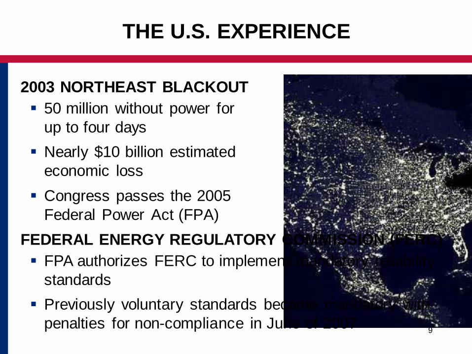
2003 NORTHEAST BLACKOUT
50 million without power for
up to four days
Nearly $10 billion estimated
economic loss
Congress passes the 2005
Federal Power Act (FPA)
THE U.S. EXPERIENCE
FEDERAL ENERGY REGULATORY COMMISSION (FERC)
FPA authorizes FERC to implement mandatory reliability
standards
Previously voluntary standards became mandatory with
penalties for non-compliance in June of 2007

10
FERC / NERC
FERC directs that standards be developed to fill identified
reliability gaps
FERC selects the North American Electric Reliability
Corporation (NERC) to develop standards and monitor
compliance
NERC delegated responsibility to eight regional entities
across the U.S. to monitor compliance
ELECTRICITY INFRASTRUCTURE
Now recognized as the single most important infrastructure
THE U.S. EXPERIENCE (CONT’D.)

11
BACKGROUND
The history of blackouts in other countries has created
significant economic loss making grid reliability essential
EAPP IC were developed by SNC-Lavalin in 2011
(dealing with interconnection issues)
Nexant addressed comments on the IC and developed a
corresponding set of Standards and Measures (included
in the IC) that describe what constitutes compliance with
each provision of the IC
REVIEW OF EAPP INTERCONNECTION CODE (IC)
12
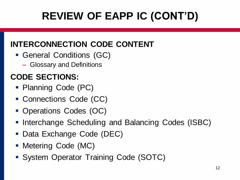
INTERCONNECTION CODE CONTENT
General Conditions (GC)– Glossary and Definitions
CODE SECTIONS:
Planning Code (PC)
Connections Code (CC)
Operations Codes (OC)
Interchange Scheduling and Balancing Codes (ISBC)
Data Exchange Code (DEC)
Metering Code (MC)
System Operator Training Code (SOTC)
REVIEW OF EAPP IC (CONT’D)

13
IC OBJECTIVES
Implement common standards for satisfactory operational
security, reliability, and quality of supply in the Interconnected
Transmission System (ITS) of Eastern Africa
Encourage integrated planning of generation capacity and
transmission expansion
Define responsibilities for the operation and management
of the ITS
Ensure that Operators are trained and authorized to take
necessary actions to maintain reliable grid operation
Comments / Questions??
REVIEW OF EAPP IC (CONT’D)
14
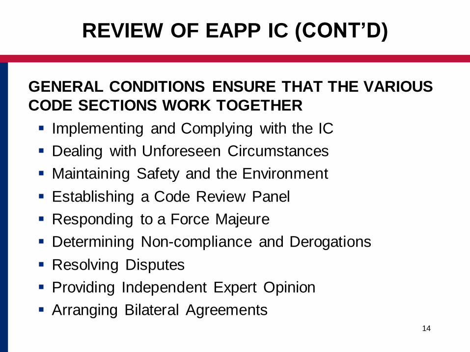
GENERAL CONDITIONS ENSURE THAT THE VARIOUS
CODE SECTIONS WORK TOGETHER
Implementing and Complying with the IC
Dealing with Unforeseen Circumstances
Maintaining Safety and the Environment
Establishing a Code Review Panel
Responding to a Force Majeure
Determining Non-compliance and Derogations
Resolving Disputes
Providing Independent Expert Opinion
Arranging Bilateral Agreements
REVIEW OF EAPP IC (CONT’D)

15
Glossary and Definitions
The Glossary and Definitions Chapters contain:– Alphabetical list of terms and their definitions
– List of acronyms and units
– Definitions of abbreviations and acronyms
REVIEW OF EAPP IC (CONT’D)

16
PLANNING CODE (PC)
The PC’s objectives are to provide for:
Coordination by the EAPP of proposed development of a
National System to ensure that Interconnected grid
operational reliability and security is not compromised
Cooperation between neighbouring grids in the planning
and procurement of new generation capacity at lowest
overall cost, and least environmental impact
Provision of sufficient information to enable a TSO to
optimise the planning and development of its National
System including the use of available transmission capacity
on the EAPP ITS
REVIEW OF EAPP IC (CONT’D)

17
PLANNING CODE (PC)
Specifies the minimum technical and design criteria,
principles, and procedures:
EAPP uses in the planning and in the medium- and long-
term development of the EAPP ITS
Member Utilities considers on a coordinated basis
Identifies the required planning data exchanged by
EAPP and TSOs to enable planning in accord with the PC
REVIEW OF EAPP IC (CONT’D)

18
CONNECTIONS CODE (CC)
The Connections Code is designed to ensure:
That new or modified connections do not impose adverse
effects upon the EAPP ITS or the new connection
That the basic rules for connection treat all TSOs and
Users in a non-discriminatory manner
Ongoing compliance with the requirements of CC will
facilitate operation of the EAPP ITS
REVIEW OF EAPP IC (CONT’D)

19
CONNECTIONS CODE (CC) (CONT’D)
Specifies the minimum technical, design and operational
criteria to be complied with by TSOs and Users when
connecting Users to an ITS:
Transmission System Performance and Characteristics –
e.g. frequency and voltage control to specified limits
Technical Performance for Plant and Apparatus – e.g.
meets relevant African and international standards
HVDC – operate and remain connected for specified
voltage and frequency variations
Protection Criteria – provide for safety, minimize
equipment damage and control the spread of disturbances
REVIEW OF EAPP IC (CONT’D)

20
CONNECTIONS CODE (CC) (CONT’D)
Generators – e.g. voltage, MW, var capability at
interconnection point
Wind Turbines – e.g. remain connected to the ITS for
specified voltage and frequency variations
Technical Requirements for Interconnected Parties – e.g.
islanding provisions
Ancillary Services – e.g. freq/cont response, voltage
control, black start capability
Maintenance Standards – requires adequate maintenance
REVIEW OF EAPP IC (CONT’D)

21
OPERATIONS CODE (OC)
Day-to-day procedures required to facilitate efficient, safe, and
coordinated operation of the ITS:
Operational Planning – e.g. coordination of planned
outages
Operational Security – e.g. n-1 contingency criterion,
voltage control, etc., next day and real time system
assessments of capacity and reserves
Emergency Operations – e.g. load shedding and
restoration plans
REVIEW OF EAPP IC (CONT’D)

22
OPERATIONS CODE (OC) (cont.)
Incident Reporting – e.g. reports of outages, low voltage
load shedding or other disturbances
Demand Control – e.g. reducing customer load as an
operational tool; automatic and manual load shed
System Tests – e.g. testing frequency or voltage variations
and testing black start capability
REVIEW OF EAPP IC (CONT’D)

23
INTERCHANGE SCHEDULING & BALANCING CODE (ISBC)
Sets out the procedures for the scheduling, coordination,
and balancing of power transfers across the ITS:
Interchange Scheduling – e.g. determination, publication
and allocation of Net Transmission Capability (NTC) to
facilitate reliable interchange
Balancing and Frequency Control – e.g. primary and
secondary frequency response and AGC
Ancillary Services – e.g. provision of operating reserves,
voltage control and black start capability
Takes Account of Coordinated Outage Scheduling
REVIEW OF EAPP IC (CONT’D)

24
DATA EXCHANGE CODE (DC)
A unified listing of all data to be exchanged by EAPP and TSOs
for the purpose of modelling steady state and dynamic
conditions for the EAPP ITS:
Power System models for different timescales
Basic Data requirements
Study Data requirements
Procedures and Responsibilities for developing and
maintaining System Models
REVIEW OF EAPP IC (CONT’D)

25
METERING CODE (MC)
Sets out the way in which power and energy flows will be
measured at the points of interchange between Control Areas:
Technical, design, and operational criteria
Accuracy and calibration
Approval, certification, and testing
Meter reading and data management
REVIEW OF EAPP IC (CONT’D)
26
STANDARDS AND MEASURES
For each Interconnection Code requirement, Nexant
developed a standard (Power Transmission Standard –
PTS) and measures
Standard describes what compliance looks like
A set of measures was developed for each standard that
can be used to demonstrate that standards are being
followed
REVIEW OF STANDARDS AND MEASURES

27
STANDARDS AND MEASURES CONTENT
Establish measures for each of the standards within the
Interconnection Codes
Identify entities subject to the requirements of the
standard (TSO, EAPP CC, etc.)
Measures contain:
– General description of what is required to comply (from the
standard content)
– Specify recommended evidence or measure to demonstrate the
requirement is met
REVIEW OF STANDARDS AND MEASURES (CONT’D)

28
RESPONSIBLE ENTITIES
Independent Regulatory Board (IRB)
EAPP Steering Committee (SC)
Code Review Panel (CRV)
EAPP Permanent Secretariat Coordination Centre (EAPP CC)
EEAP Subcommittee on Planning (SCP)
REVIEW OF STANDARDS AND MEASURES (CONT’D)

29
RESPONSIBLE ENTITIES (cont’d)
EAPP Subcommittee on Operations (SCO)
EAPP Subcommittee on the Environment (SCE)
Transmission System Operator (TSO)
Generator (Gen)
Distribution User (Duser) – user or distributor that serves
load but has no generation (Duser’s are responsible for
UFLS for example)
REVIEW OF STANDARDS AND MEASURES (CONT’D)
30
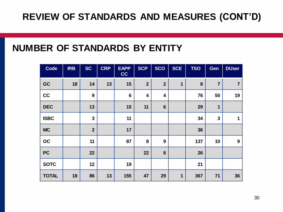
NUMBER OF STANDARDS BY ENTITY
REVIEW OF STANDARDS AND MEASURES (CONT’D)
Code IRB SC CRP EAPP
CC
SCP SCO SCE TSO Gen DUser
GC 18 14 13 15 2 2 1 8 7 7
CC 9 6 4 4 76 50 19
DEC 13 15 11 6 29 1
ISBC 3 11 34 3 1
MC 2 17 36
OC 11 87 8 9 137 10 9
PC 22 22 6 26
SOTC 12 19 21
TOTAL 18 86 13 155 47 29 1 367 71 36

31
MAINTENANCE OF STANDARDS
These standards were based on experience in other parts
of the world
It is expected that they will evolve to meet the needs of
Eastern Africa
They should be viewed as living documents
The General Conditions provide for a Code Review Panel
to recommend changes as needed
The Code Review Panel, once established, takes
ownership of the Standards
REVIEW OF STANDARDS AND MEASURES (CONT’D)

32
CODE REVIEW PANEL
Group established by the EAPP Steering Committee:
– Reviews and analyzes proposed changes to the IC
– Recommends changes to the EAPP Steering
Committee and IRB
REVIEW OF STANDARDS AND MEASURES (CONT’D)

33
Examples of IC
Examples of Standards
INTERCONNECTION CODE EXAMPLES
Interconnection Code
Standards
Measures

34
EXAMPLES OF IC AND STANDARDS
Connections Code (CC)
Scope:
– The CC specifies the minimum technical, design, and operational
criteria of Plant and Apparatus which must be complied with by the
TSOs and Users at the Connection Point in order to maintain
secure and stable operation
– The CC applies to TSOs and Users connected or seeking
connection to the ITS
INTERCONNECTION CODE EXAMPLES (CONT’D)

35
EXAMPLES OF IC AND STANDARDS
Standard CC-001 (applies to EAPP CC, TSO)
The frequency of the EAPP ITS is controlled to between
49.5 Hz — 50.5 Hz (within plus or minus 1%) under normal
operation, unless exceptional circumstances prevail
INTERCONNECTION CODE EXAMPLES (CONT’D)

36
EXAMPLES OF IC AND STANDARDS
Standard CC-001 Measures
Procedures for frequency monitoring and control are
documented and implemented
Tools used to monitor and control frequency are described
and implemented
System frequency is recorded and stored for analysis
When system frequency falls below 49.5 Hz or exceeds
50.5 Hz, the exceptional circumstances causing the
deviation are logged and reported
INTERCONNECTION CODE EXAMPLES (CONT’D)

37
EXAMPLES OF IC AND STANDARDS
Therefore Standard CC-001:
Is part of a set of requirements for the critical function of
maintaining frequency
For frequency deviations, requirements include automatic
and manual generation control
For extreme deviations (for instance the loss of several
large generating units) requirements include UFLS and
manual load shed to prevent uncontrolled cascading
outages
INTERCONNECTION CODE EXAMPLES (CONT’D)

38
EXAMPLES OF IC AND STANDARDS
Standard OC-032 (applicable to: EAPP CC, TSO)
The loss of any element of the EAPP ITS does not cause:
• Frequency deviation outside operating limits
• Voltage deviation leading to voltage instability
• Thermal overloading of equipment
• Islanding of any part of the EAPP ITS
• Angular instability in the EAPP ITS
• Cascading Outages
INTERCONNECTION CODE EXAMPLES (CONT’D)
39
EXAMPLES OF IC AND STANDARDS
Standard OC-032 Measures
A procedure exists that define the parameters for
acceptable frequency ranges, allowable voltage limits,
thermal loading limits, and voltage and angular stability
criteria under normal and (n-1) contingency conditions.
The procedure includes a description of the types and
frequency of studies that need to be performed
INTERCONNECTION CODE EXAMPLES (CONT’D)

40
EXAMPLES OF IC AND STANDARDS
Standard OC-032 Measures (cont’d)
Studies are performed in accordance with the
requirements in the procedures and the study results are
documented
It is acceptable in some cases for TSOs to allow for loss of
load on condition that its magnitude is compatible with
secure operation and is predictable and locally limited.
INTERCONNECTION CODE EXAMPLES (CONT’D)

41
EXAMPLES OF IC AND STANDARDS
Standard OC-032 (cont’d)
For instance for an unexpected loss of the largest
contingency, Standard OC-032 requires procedures in place
to ensure that:
The system remains in the normal secure state
Sufficient generating resources are on line and can replace
the loss quickly to maintain frequency and control ACE
No appreciable loss of load
INTERCONNECTION CODE EXAMPLES (CONT’D)

42
EXAMPLES OF IC AND STANDARDS
Standard OC-032 (cont’d)
Which means that TSOs:
Must activate contingency reserves to make up for any lost generation
Must ensure that frequency is restored by ensuring that primary and secondary (if necessary) frequency response activates
Must determine if unforeseen voltage issues arise and activate VAR resources as necessary
INTERCONNECTION CODE EXAMPLES (CONT’D)

43
EXAMPLES OF IC AND STANDARDS
Standard OC-123,124,125 Automatic Load Shedding
(applicable to TSO, EAPP CC, TSO respectively
OC-123: TSO established plans for automatic load
shedding for underfrequency and undervoltage conditions
OC-124: EAPP-CC coordinates the overall Automatic
Load Shedding Scheme for the ITS to prevent excessive
transfers and possible instability
OC-125: TSO implements load shedding in steps to
minimize the risk of further uncontrolled separation, loss of
generation, or system shutdown
INTERCONNECTION CODE EXAMPLES (CONT’D)

44
EXAMPLES OF IC AND STANDARDS
Standard OC-123,124,125 sample measures
TSOs have plans for UFLS and UVLS
Controls and instrumentation are installed and tested to
enable automatic load shedding plans when needed
Details of the plans and constraints to their implementation
are documented and communicated to EAPP CC
EAPP CC maintains an up-to-date list of individual TSOs
Load Shedding Plans and coordinates the ITS-wide plan
TSOs have procedures for implementing load shedding in
steps to minimize further reliability risk to the ITS
INTERCONNECTION CODE EXAMPLES (CONT’D)

45
TOPICS:
CME entities
Self reporting
Mitigation
Penalties
Appeals
Culture of compliance/reliability
US COMPLIANCE MONITORING AND ENFORCEMENT
(CME)

46
US COMPLIANCE ENFORCEMENT AUTHORITY (CEA)
The US CEA is NERC which has acts as the Electric
Reliability Organization appointed by FERC
NERC delegates authority to eight regional entities who are
the CEA in their respective regions
NERC and FERC oversee all compliance activities
US COMPLIANCE MONITORING AND ENFORCEMENT
(CONT’D)

47
SELF-REPORTING (US)
When an entity subject to the standards is not in
compliance it self-reports the circumstances to the CEA
Entities can self-report with a mitigation plan and timeline
CEAs typically can reduce compliance actions, penalties
and audit frequency for such good behavior
US COMPLIANCE MONITORING AND ENFORCEMENT
(CONT’D)

48
MITIGATION (US)
Usually an entity that self-reports a violation provides a
mitigation plan at the same time (applicable when self-
reporting is developed)
The mitigation plan usually includes details of the
violation, corrective actions planned and a timetable for
completing the corrective actions
This can forestall further enforcement measures because
it provides assurance to the CEA that the violation will be
adequately and timely addressed
US COMPLIANCE MONITORING AND ENFORCEMENT
(CONT’D)
49
CULTURE OF COMPLIANCE/RELIABILITY (US)
Timely and comprehensive self-reporting and mitigation
form the foundation of a culture of compliance and
reliability
Grid reliability is the first priority and good utility practices
and procedures follow from this priority
Attaining reliable planning and operation of the grid
through good utility practice most often results in
compliance with the standards
US COMPLIANCE MONITORING AND ENFORCEMENT
(CONT.)

50
ENFORCEMENT/PENALTIES (US)
Compliance monitoring and self-reporting may not provide
adequate assurance that the grid is reliable and standards
are being met
Financial penalties can provide greater motivation for
compliance
Penalties can be structured to disallow non-compliant
entities to buy and sell across interconnections until they
demonstrate compliance
Fines can be levied based on the severity of the violation
US COMPLIANCE MONITORING AND ENFORCEMENT
(CONT’D)

51
APPEALS (US)
An appeal process allows entities who believe they have
been unfairly penalized to appeal decisions for further
consideration
– For example, if a CEA levies fines, appeals are made to NERC for
its analysis and decision.
– NERC has a team responsible for resolving appeals
– Entities have the right to further seek appeal to FERC
– FERC has the right to monitor all appeals and intervene as deemed
appropriate whether or not the appeal is brought to it
US COMPLIANCE MONITORING AND ENFORCEMENT
(CONT’D)
52
Implementation of compliance monitoring
Implementation of audits
Lessons learned from the U.S. experience
FUTURE CONSIDERATIONS

53
IC GAP ANALYSIS TOOL

54
Opening and Introductions
Workshop Objectives
Grid Code and Standards
Background
Compliance Monitoring and Enforcement
User Experiences
Gap Analysis Tool
Future Considerations
Hands-on experience
Discussion
Closing
AGENDA

55
GAP ANALYSIS

56
GAP IS THE DIFFERENCE BETWEEN TWO STATES OF
DEVELOPMENT
For this Gap Analysis, a GAP is the difference between:
– State 1: The state that exists today
– State 2: The desired state that should exist at the time of full
compliance with the IC
State 2 is the time at which two
control areas are interconnected
and in full compliance with an IC
WHAT IS A GAP?

57
SIMPLE-TO-USE TOOL TO HELP RESPONSIBLE PARTIES:
The tool is a Excel workbook, Gap Analysis Workbook, that
has been developed for each Responsible Party type:
Identify the Current State by conducting an assessment
of existing procedures and tools to determine if they meet
the Standards (or part of the Standards)
Identify the gap(s) between their Current State and Desired
State to be fully compliant with the IC
Summarize planned actions and assign responsibilities
for closing the identified gaps
GAP ANALYSIS TOOL

58
INFO TAB
Responsible Party Type
Responsible Party Acronym*
Responsible Party Name
Date Last Updated
*The Responsible Party acronym is used only in the Gap Analysis tab to create a
unique Gap Index number. The remaining items are for information only.
Responsible Party Type: CRP
Responsible Party Acronym: SAMP
Responsible Party Name: Code Review Panel
Date Last Updated: 8-May-12
GAP ANALYSIS WORKBOOK DETAILS
59
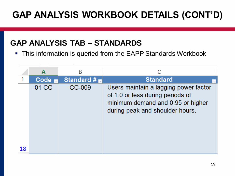
GAP ANALYSIS TAB – STANDARDS
This information is queried from the EAPP Standards Workbook
GAP ANALYSIS WORKBOOK DETAILS (CONT’D)
60
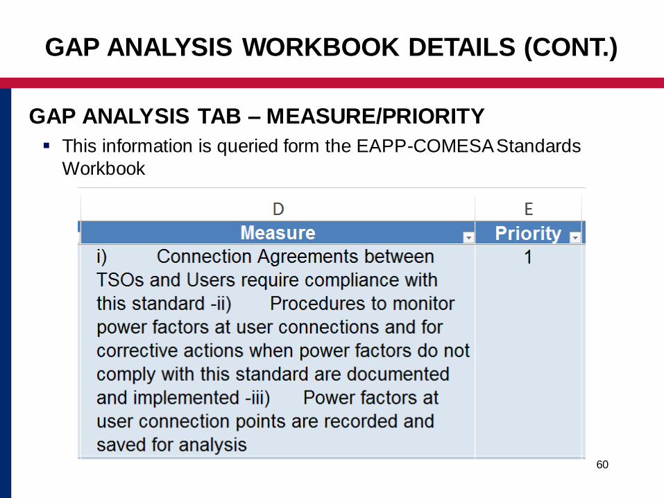
GAP ANALYSIS TAB – MEASURE/PRIORITY
This information is queried form the EAPP-COMESA Standards
Workbook
GAP ANALYSIS WORKBOOK DETAILS (CONT.)

61
Action Step Tool - Priority Definitions
Note the priority for each measure is pre-determined and cannot be
changed
GAP ANALYSIS WORKBOOK DETAILS (CONT.)
Priority Description Priority
Implement prior to commencing interconnected system operation
1
Required for reliable system operation under normal and n-1 conditions
2
Required to deal with more severe and less frequent emergencies
3
Required to optimize economic operation and facilitate markets
4

62
GAP ANALYSIS TAB – CURRENT STATE / DATE / GAP
GAP ANALYSIS WORKBOOK DETAILS (CONT’D)
63
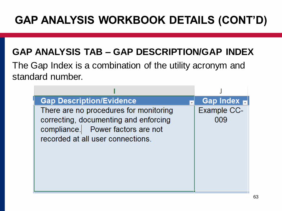
GAP ANALYSIS TAB – GAP DESCRIPTION/GAP INDEX
The Gap Index is a combination of the utility acronym and
standard number.
GAP ANALYSIS WORKBOOK DETAILS (CONT’D)

64
GAP ANALYSIS TAB – ACTION PLAN / RESPONSIBLE
PERSON
GAP ANALYSIS WORKBOOK DETAILS (CONT’D)

65
PREREQUISITES
Familiarity with EAPP Interconnection Codes
Identify Applicable Roles
Knowledge of Responsibility Party’s existing procedures,
tools, and other items that might result in the party’s
compliance or need for modification to reach compliance
HOW TO USE THE GAP ANALYSIS TOOLS

66
SECTIONS TO BE COMPLETED BY THE RESPONSIBLE
PARTY
Current State – A description of the current state as evaluated by the
Responsible Party
As of Date – Date the current state was evaluated
Gap? – Yes or No
Gap Description/Evidence
‒ If Gap? Yes. Provide a description of the difference between the current
stat and the standard
‒ If Gap? No. Provide a description of the evidence showing that the
standard is met.
Gap Index – Automatically generated (no action required)
Action Plan – Assign and group gaps to action plans
Required actions are in red italics
HOW TO USE THE GAP ANALYSIS TOOLS (CONT’D)

67
TSO EXAMPLES:
Standard CC-009: Users maintain a lagging power factor
(PF) of 1.0 or less during periods of minimum demand
and 0.95 or higher during peak and shoulder hour
Measures:
‒ Connection Agreements between TSOs and Users require
compliance with this standard;
‒ Procedures to monitor power factors at user connections and for
corrective actions when PFs do not comply with this standard are
documented and implemented;
‒ User connection points PFs are recorded and saved for analysis
GAP ANALYSIS TOOL EXAMPLE

68
CURRENT STATE
Connection Agreement stipulates operations at 0.90 PF to
unity. There are no procedures for monitoring, correcting,
documenting, and enforcing compliance. PF is recorded at
some user connection points.
AS OF DATE
6-Aug-15 (date of evaluation)
GAP
Y
GAP DESCRIPTION / EVIDENCE
There are no procedures for monitoring, correcting,
documenting, and enforcing compliance. PFs are not
recorded at all user connections
GAP ANALYSIS TOOL EXAMPLE (CONT’D)
69
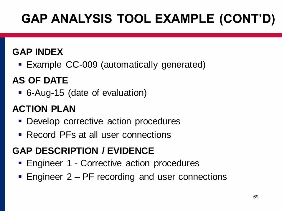
GAP INDEX
Example CC-009 (automatically generated)
AS OF DATE
6-Aug-15 (date of evaluation)
ACTION PLAN
Develop corrective action procedures
Record PFs at all user connections
GAP DESCRIPTION / EVIDENCE
Engineer 1 - Corrective action procedures
Engineer 2 – PF recording and user connections
GAP ANALYSIS TOOL EXAMPLE (CONT’D)

70
The Gap Analysis Tools are based on the current version
of the Standards
It is expected that the Standards will evolve to meet the
needs of East Africa
The Code Review Panel will be responsible for
recommending changes to the Standards
The IRB and SC have responsibilities for approving
changes
Any changes to the standards need to be reflected in the
Gap Analysis Tools
The Power Transmission Standards Guide describes a
process for updating the Gap Analysis Tools
MAINTENANCE OF GAP ANALYSIS TOOLS

71
DISCUSSION AND QUESTIONS
Related Documents