EAST WEST CONNECT Ltd / BS 7671:2018 Ed AMTECH TEMPLATE TEST CERTIFICATE TYPES 1. ELECTRICAL INSTALLATION CERTIFICATE 2. REFERENCE SHEET 3. DOMESTIC ELECTRICAL INSTALLATION CERTIFICATE 4. MINOR ELECTRICAL INSTALLATION WORKS CERTIFICATE 5. ELECTRICAL INSTALLATION CONDITIONAL REPORT 6. DESIGN,INSTALLATION,DETECTION OF FIRE ALARMS IN DWELLINGS 7.SITE TEMPS INSTALLATION (Short Version) Electrical Test Certificate Templates (18th Edition) CON-FM-79 1 of 40 Revision 00 Scope This document contains blank templates for Electrical Testing Certificates designed to meet the requirements of BS7671:2018 - IET Wiring Regulations 18th Edition. It is East West Connects Policy to use these Templates for recording all Test and Inspection works carried out on behalf of East West Connect. Electrical Testing and Inspection Processes, Certification and record keeping are managed by the East West Connect Testing Department and connected works MUST be carried out in accordance with these processes. Templates contained within this document are as follows:

Welcome message from author
This document is posted to help you gain knowledge. Please leave a comment to let me know what you think about it! Share it to your friends and learn new things together.
Transcript

EAST WEST CONNECT Ltd / BS 7671:2018 Ed AMTECH TEMPLATE TEST CERTIFICATE TYPES
1. ELECTRICAL INSTALLATION CERTIFICATE2. REFERENCE SHEET3. DOMESTIC ELECTRICAL INSTALLATION CERTIFICATE4. MINOR ELECTRICAL INSTALLATION WORKS CERTIFICATE5. ELECTRICAL INSTALLATION CONDITIONAL REPORT6. DESIGN,INSTALLATION,DETECTION OF FIRE ALARMS IN DWELLINGS7.SITE TEMPS INSTALLATION (Short Version)
Electrical Test Certificate Templates (18th Edition)
CON-FM-79 1 of 40 Revision 00
ScopeThis document contains blank templates for Electrical Testing Certificates designed to meet the requirements of BS7671:2018 - IET Wiring Regulations 18th Edition. It is East West Connects Policy to use these Templates for recording all Test and Inspection works carried out on behalf of East West Connect.Electrical Testing and Inspection Processes, Certification and record keeping are managed by the East West Connect Testing Department and connected works MUST be carried out in accordance with these processes.
Templates contained within this document are as follows:

being the person(s) responsible for the design of the electrical installation (as indicated by signature(s) below), particulars of which are described above, have
exercised reasonable skill and care when carrying out the design hereby CERTIFY that the design work for which have been responsible is, to the best of
knowledge and belief in accordance with BS 7671 amended to (date) except for the departures, if any detailed as follows:
being the person(s) responsible for the construction of the electrical installation (as indicated by signature(s) below), particulars of which are described
above, have exercised reasonable skill and care when carrying out the construction hereby CERTIFY that the construction work for which have been responsible
is, to the best of knowledge and belief in accordance with BS 7671 amended to (date) except for the departures, if any detailed as follows:
Address
Extent of the
installation
covered by this
certificate
New
An
Addition
An
Alteration
The extent of liability of the signatory or signatories is limited to the work described above as the subject of this certificate.
For the DESIGN of the installation:
Signature
Signature
Date
Date
Name (CAPITALS)
Name (CAPITALS)
**(where there is divided responsibility for the design)
Details of departures from BS 7671, as amended (Regulations 120.3, 133.1.3 and 133.5)
The extent of liability of the signatory is limited to the work described above as the subject of this certificate.
For the CONSTRUCTION of the installation:
Signature Date Name (CAPITALS)
Client/Address
Details of departures from BS 7671, as amended (Regulations 120.3, 133.1.3 and 133.5)
The extent of liability of the signatory is limited to the work described above as the subject of this certificate.
For the INSPECTION AND TESTING of the installation:
Signature Date
Name (CAPITALS) Inspector
Signature Date
Name (CAPITALS) Qualified
Supervisor
The installation is:
Designer 1
Designer 2 **
Constructor
Details of departures from BS 7671, as amended (Regulations 120.3, 133.1.3 and 133.5)
Reviewed by
Details of permitted exceptions
(Regulations 411.3.3):
being the person(s) responsible for the inspection and testing of the electrical installation (as indicated by signature(s) below), particulars of which are
described above, have exercised reasonable skill and care when carrying out the inspection and testing hereby CERTIFY that the work for which have been
responsible is, to the best of knowledge and belief in accordance with BS 7671 amended to (date) except for the departures, if any detailed as
follows:
Where applicable, a suitable risk assessment(s)
must be attached to this Certificate:Number of pages:
ELECTRICAL INSTALLATION
CERTIFICATE [BS 7671:2018 as
amended]
Page 1 of 7Copyright © Trimble 2018, FastTest Plus v2018.0.0, Demonstration Only
Details of the Clien
Details of the Installatio
Design
Construction
Inspection and Testing
ELECTRICAL INSTALLATION
CERTIFICATE [BS 7671:2018 as
amended]
Details of the Client
Details of the Installation
Design
Construction
Inspection and Testing

OrganisationDESIGN (1)
Address
DESIGN (2) Organisation
CONSTRUCTION
Address
Organisation
INSPECTION AND TESTING
Address
Organisation
Address
Tel
Tel
Tel
Tel
Number and Type of Live Conductors
a.c.
1-Phase
(2 wire)
1-Phase
(3 wire)
2-Phase
(3 wire)
3-Phase
(3 wire)
3-Phase
(4 wire)
d.c.
2
Pole
3
Pole
Other
System Type(s)
TN-S
TT
IT
TN-C-S
TN-C
Other
Characteristics of primary supply
overcurrent protective Device(s)
BS(EN)
Type
Rated current
Nature of Supply Parameters
Nominal
Voltage
Nominal
frequency
Prospective
fault current
External loop
impedence
f
Ze
V
Hz
kA
Ω
A
Number of
Sources
VUo
kAShort circuit
Capacity
Distributor's
facility
Installation
earth electrode
Means of Earthing Details of Installation Earth Electrode (where applicable)
LocationType
(eg rod(s), tape etc)
Main Switch/ Switch-Fuse/ Circuit-Breaker/ RCD
Type BS(EN)
RCD
operating
current, l∆n
RCD
operating
time at, l∆n
No. of poles
Ω
mA
ms
Electrode
resistance,R
Method of
measurement
Maximum Demand (Load) Protective measure(s) against electric shock
Supply
Conductors
material
Supply
Conductors
CSA
Voltage
Rating
Rated
Current,In
V
A
Main protective bonding
conductors
Conductor
csa:
Conductor
material:
Continuity verifed
Conductor
material:
Conductor
csa:
Continuity verified
Bonding of extraneous
conductive parts ( )
Water installation pipes
Oil installation pipes
Gas installation pipes
Other
Structural Steel
In the case of an addition or alteration see regulation 644.1.2:
, the designer(s) RECOMMEND that this installation is further inspected and tested after an interval of not more than
U
lpf
A
mm2 2
mm
2mm
or change of tenancy.
Lightning Protection
msRated time
delay
Earthing conductor
Tick boxes and enter details, as appropriate
Confirmation of
Supply Polarity
Connection verifiedConnection verifed
(1)
(1)
(1)
(2)
(2)
(1) by enquiry
(2) by enquiry or by
measurement
Next Inspectio
Branch No.(If
Applicable)
Branch No.(If
Applicable)
Registration No.
(where appropriate)
Branch No.(If
Applicable)
Branch No.(If
Applicable)
Registration No.
(where appropriate)
Registration No.
(where appropriate)
Registration No.
(where appropriate)
Page 2 of 7Copyright © Trimble 2018, FastTest Plus v2018.0.0, Demonstration Only
Particulars of the Organisation(s) Responsible for the Electrical In
Supply Characteristics and Earthing Arrangem
Particulars of Installation at the Origin
Comments on Existing Installation:
Particulars of the Organisation(s) Responsible for the Electrical Installation
Supply Characteristics and Earthing Arrangements
Particulars of Installation at the Origin
Comments on Existing Installation:
Next Inspection

Not applicable
Item No Description Outcome Item No Description Outcome
1.0
External condition of electrical intake equipment
(visual inspection only)(If inadequacies are identified with the intake equipment it is
recommended the person ordering the report informs the appropriate
authority.)
6.0 Basic and fault protection
1.1 Service cable a) SELV
1.2 Service head b) PELV
1.3 Earthing arrangement c) Double insulation
1.4 Meter tails d) Reinforced insulation
1.5 Metering equipment 7.0 Distribution equipment
1.6 Isolator (where present) 7.1 Working space/accessibility adequate/satisfactory
2.0 Parallel or switched alternative sources of supply 7.2 Security of fixing
2.1Presence of adequate arrangements where generator to operate as
a switched alternative:7.3 Insulation of live parts not damaged during erection
a)Dedicated earthing arrangement independent of that of the public
supply7.4 Adequacy/security of barriers
2.2Presence of adequate arrangements where generator to operate in
parallel with public supply system:7.5 Suitability of enclosures for IP and fire ratings
a) Correct connection of generator in parallel 7.6 Enclosures not damaged during installation
b) Compatibility of characteristics of means of generation 7.7 Presence and effectiveness of obstacles
c)
Means to provide automatic disconnection of generator in the event
of loss of public supply or voltage or frequency deviation beyond
declared values
7.8 Main switch(es): presence and operation (functional check)
d)
Means to prevent connection of generator in the event of loss of
public supply or voltage or frequency deviation beyond declared
values
7.9Components are suitable according to manufacturers' assembly
instructions or literature
e) Means to isolate generator from public supply 7.10 Circuit-breaker and RCDs operation to prove functionality
2.3 Presence of alternative/additional supply warning notices at or near: 7.11 RCD(s) provided for fault protection where specified
a) The origin 7.12 RCD(s) provided for protection against the risk of fire where present
b) The meter position if remote from origin 7.13 RCD(s) provided for additional protection where specified
c)The consumer unit/distribution board to which the alternative/
additional sources are connected7.14
Confirmation overvoltage protection (SPDs) provided where
specified
d) All points of isolation of ALL sources of supply 7.15 SPDs functioning/operating as expected
3.0 Automatic disconnection of supply 7.16Selection of protective devices(s) and base(s); correct type and
rating
3.1Presence and adequacy of protective earthing/bonding
arrangements as follows:7.17 Single-pole protective devices in line conductors only
a)Distributor's earthing arrangement or installation earth electrode
arrangement7.18
Protection against mechanical damage where cables enter
equipment
b) Earthing conductor and connections 7.19Protection against electromagnetic effects where cables enter
ferromagnetic enclosures
c) Main protective bonding conductors and connections 7.20
Confirmation that ALL conductor connections including connections
to busbars are correctly located in terminals and are tight and
secure
d) Earthing/bonding labels at all appropriate locations 7.21 Presence of RCD six-monthly test notice where required
3.2 Accessibility of: 7.22Presence of diagrams, charts or schedules at or near each
distribution board where required
a) Earthing conductor connections 7.23 Presence of next inspection recommendation label
b) All protective bonding connections 7.24Presence of non-standard (mixed) cable colour warning notice at or
near the appropriate distribution board where required
3.3 FELV-requirements satisfied 7.25 Presence of other required labelling
3.4Nominal line to line voltage does not exceed 110V and the nominal
line to earth voltage does not exceed 63.5V
4.0 Basic protection
4.1 Provisions for basic protection where specified:
a) Insulation of live parts
b) Barriers or enclosures
c) Obstacles
d) Placing out of reach
5.0 Additional protection
5.1The presence and effectiveness of additional protection methods
used as follows:
a) RCDs should not exceed 30 mA
b) Supplementary bonding
Acceptable
conditionOutcomes N/A
Schedule of Items Inspected
Page 3 of 7Copyright © Trimble 2018, FastTest Plus v2018.0.0, Demonstration Only
Schedule of Items Inspected

N/ANot applicableAcceptable
conditionOutcomes
Item No Description Outcome Item No Description Outcome
8.0 Circuits 9.0 Isolation and switching
8.1 Identification of conductors 9.1 Isolators:
8.2Cables correctly supported throughout with protection against
abrasiona) Presence and location of appropriate devices
8.3Examination of cables for signs of mechanical damage during
installationb) Capable of being secured in the OFF position
8.4Examination of installation/insulation of live parts not damaged
during erectionc) Correct operation verified (functional check)
8.5Non-sheathed cables protected by enclosure in conduit,
ducting or trunkingd)The installation, circuit or part thereof that will be isolated is
clearly identified by location and/or durable marking
8.6 Suitability of containment systems (including flexible conduit) e)Warning notice posted in situations where live parts cannot be
isolated by the operation of a single device
8.7 Correct temperature rating of cable insulation 9.2 Switching off for mechanical maintenance:
8.8Adequacy of cables for current-carrying capacity with regard to
the type and nature of installationa) Presence of appropriate devices
8.9Adequacy of protective devices: type and fault current rating
for fault protectionb)Acceptable location (local or
remote)
8.10 Operation/adequacy of AFDD(s) where present c) Capable of being secured in the OFF position
8.11 Presence and adequacy of circuit protective conductors d) Correct operation verified (functional check)
8.12Coordination between conductors and overload protective
devicese)The installation circuit or part thereof to be disconnected
clearly identified by location and/or durable marking
8.13
Wiring systems and cable installation methods/practices
appropriate to the type and nature of installation and external
influences
9.3 Emergency switching/stopping:
8.14Cables concealed under floors above ceilings in walls/
partitions adequately protected against damagea) Presence of appropriate devices
8.15Cables that are installed in walls/partitions installed in
prescribed zonesb) Readily accessible for operation where danger might occur
8.16Provision of additional protection by RCDs having rated
residual operating current (I delta n) not exceeding 30 mA for:c) Correct operation verified (functional check)
a)- all socket-outlets with a rated current not exceeding 32 A or
less unless exemptd)The installation, circuit or part thereof to be disconnected
clearly identified by location and/or durable marking
b)- supplies to mobile equipment with a current rating not
exceeding 32 A for use outdoorse) Firefighter's switches present/operating (where required)
c)- cables concealed in walls/partitions at a depth of less than
50 mm9.4 Functional switching:
d)- cables concealed in walls/partitions containing metal parts
regardless of deptha) Presence of appropriate devices
e)- circuits supplying luminaires within domestic (household)
premises onlyb) Correct operation verified (functional check)
8.17Provision of fire barriers sealing arrangements so as to
minimise the spread of fire10.0 Current-using equipment (permanently connected)
8.18 Band II cables segregated/separated from Band I cables 10.1 Suitability of equipment in terms of IP and fire ratings
8.19 Cables segregated/separated from non-electrical services 10.2Enclosure not damaged/deteriorated during installation so as
to impair safety
8.20 Termination of cables at enclosures: 10.3 Suitability for the environment and external influences
a) Connections under no undue strain 10.4 Security of fixing
b) No basic insulation of a conductor visible outside enclosure 10.5Cable entry holes in ceilings above luminaires, sized or sealed
so as to restrict the spread of fire
c) Connections of live conductors adequately enclosed 10.6 Recessed luminaires (downlighters):
d) Adequately connected at point of entry to enclosure a) Correct type of lamps fitted
8.21 Suitability of circuit accessories for external influences b) Installed to minimise build-up of heat
8.22 Circuit accessories not damaged during erection 10.7 Provision of undervoltage protection, where specified
8.23Single-pole devices for switching or protection in line
conductors only10.8 Provision of overload protection, where specified
8.24Adequacy of connections including CPCs within accessories
and at fixed and stationary equipment10.9 Adequacy of working space/accessibility to equipment
11.0Special installations or locations
List below any special installations or locations which are part of the installation to be verified, and confirm that the additional requirements given in the respective section of Part 7 are fulfilled:
Schedule of Items Inspected
Page 4 of 7Copyright © Trimble 2018, FastTest Plus v2018.0.0, Demonstration Only
Schedule of Items Inspected

Signature:
Name: Date:
12.0 Other Outcome
Schedules of Inspections and Schedules of Test Results
The attached Schedules are part of this document and this Certificate is valid only when they are attached to it
Schedule of Items Inspected
Page 5 of 7Copyright © Trimble 2018, FastTest Plus v2018.0.0, Demonstration Only
Schedule of Additional Records (See attached schedule)
Inspected By
Schedule of Items Inspected
Inspected By
Schedule of Additional Records (See attached schedule)

Maxpermitted
disconnection
times(s)
Live
mm 22
Supply to
distribution
board is from:
No of phases
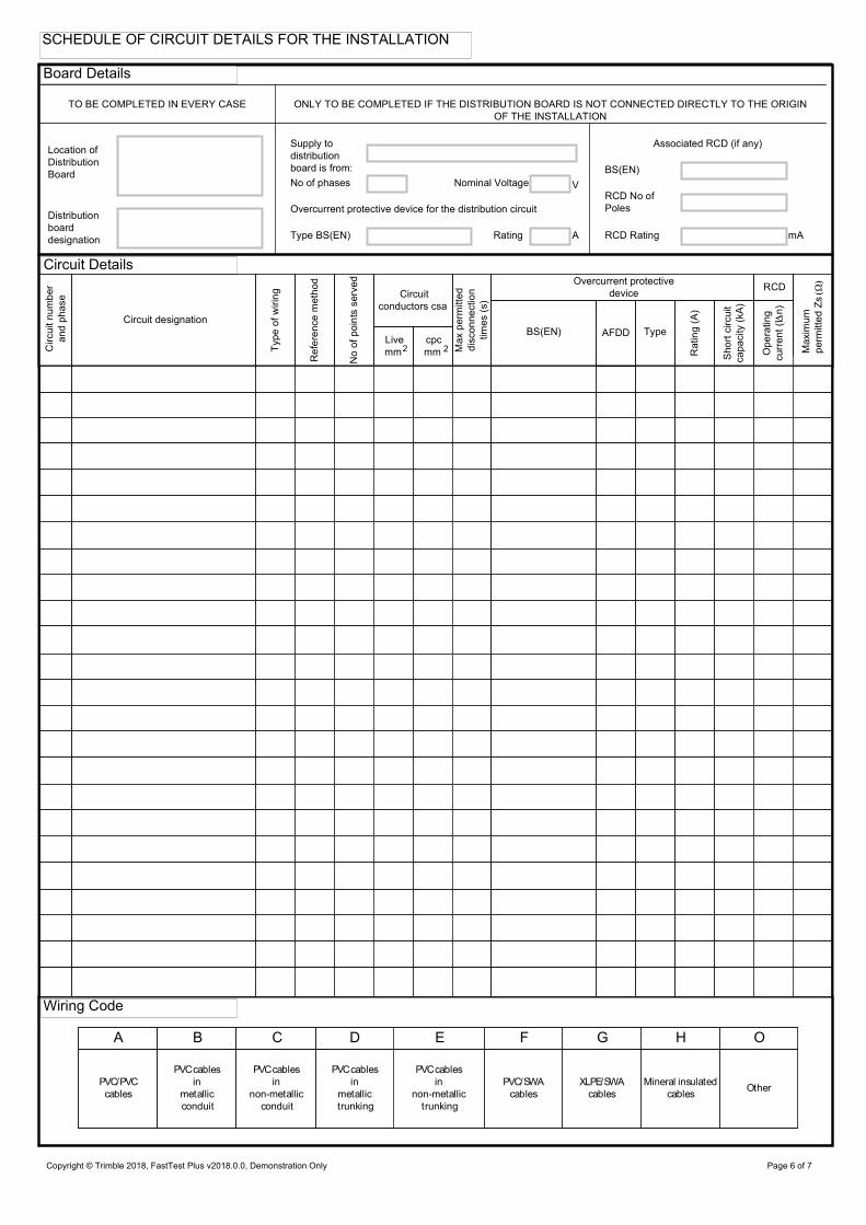
TO BE COMPLETED IN EVERY CASE ONLY TO BE COMPLETED IF THE DISTRIBUTION BOARD IS NOT CONNECTED DIRECTLY TO THE ORIGIN
OF THE INSTALLATION
Overcurrent protective device for the distribution circuit
Associated RCD (if any)
BS(EN)
RCD No of
Poles
RCD Rating
A B C D E F G H O
PVC/PVC
cables
PVCcables
in
metallic
conduit
PVCcables
in
non-metallic
conduit
PVCcables
in
metallic
trunking
PVCcables
in
non-metallic
trunking
PVC/SWA
cables
XLPE/SWA
cables
Mineral insulated
cablesOther
Nominal Voltage
Type BS(EN) Rating
Maximum
permittedZs
Circuitnumber
andphase
Circuit designation
Typeofwiring
Referencemethod
Noofpointsserved
Circuit
conductors csa
cpc
mm
Overcurrent protective
deviceRCD
Type
Rating(A)
Shortcircuit
capacity(kA)
Operating
current(In)
BS(EN)
A
V
mA
Location of
Distribution
Board
Distribution
board
designation
AFDD
Circuit Details
Wiring Code
SCHEDULE OF CIRCUIT DETAILS FOR THE INSTALLATION
Board Details
Page 6 of 7Copyright © Trimble 2018, FastTest Plus v2018.0.0, Demonstration Only
SCHEDULE OF CIRCUIT DETAILS FOR THE INSTALLATION
Board Details
Circuit Details
Wiring Code

ms
Remarks
seecontinuation
sheet
Maximum
measured
earth fault
loop
impedance
TEST INSTRUMENTS (SERIAL NUMBERS) USED
Circuit
number
and
phase
Circuit Impedances
Polarity(v)
Live/
Neutral
Operatingtime
atI
Insulation resistance
Live/
Earth
Testbutton
operation
r1 (Line) rn (Neutral) r2 (cpc) (R1 + R2) (R2)
All circuits
(At least one
column
to be completed)Live/
Live
Earth/
Neutral
Date of
testing
Position
Name
Signature
IpfZs kA
Operating times of associated RCD (if any) At I n
Ring final circuits only
(measure end to end)
RCD
Phase sequence confirmed
(where appropriate)
Correct supply polarity confirmed
Insulation
resistance
Multi-
function
RCD
Earth fault
loop
impedance
Continuity Other
n(ms)
Test
Voltage
AFDDTestbutton
operation
Supplementary Conductors
TO BE COMPLETED IN EVERY CASE
ONLY TO BE COMPLETED IF THE DISTRIBUTION BOARD IS NOT CONNECTED
DIRECTLY TO THE ORIGIN OF THE INSTALLATION
SCHEDULE OF CIRCUIT TESTS FOR THE INSTALLATION
Board Tests
Circuit Tests
Tested By
Details of circuits and/or equipment vulnerable to damage when testing
Page 7 of 7Copyright © Trimble 2018, FastTest Plus v2018.0.0, Demonstration Only
SCHEDULE OF CIRCUIT TESTS FOR THE INSTALLATION
Board Tests
Details of circuits and/or equipment vulnerable to damageh t ti
Circuit Tests
Tested By


Trimble FastTest
Reference sheet 3
The following list of devices are numbered to correspond to the list provided within FastTest. In
order to save time simply note the reference number on your site inspection pack and then select
that reference from within the program. The correct device will then be printed on your completed
certificates.
General Protective Devices
Reference Number Device
1 BS 88-2 Fuse HRC gG (General)
2 BS 88-2 Fuse HRC mG (Motor)
3 BS 3036 Fuse Re-Wireable (semi-enclosed)
30
4 BS 1361 Fuse HBC Domestic Type 1
5 BS 1361 Fuse HBC Domestic Type 2
6 BS 1362 Fuse Domestic
7 Fuse Obsolete Type
8 BS EN 60898 MCB Type B
9 BS EN 60898 MCB Type C
10 BS EN 60898 MCB Type D
11 BS 3871 MCB Type 1
12 BS 3871 MCB Type 2
13 BS 3871 MCB Type 3
14 BS 3871 MCB Type 4
15 MCB Obsolete Type
16 BS EN 60947-2 MCCB
17 MCCB Obsolete Type
18 BS EN 60947-2 ACB
19 ACB Obsolete Type
20 BS EN 60947-2 MCB Type B
21 BS EN 60947-2 MCB Type C
22 BS EN 60947-2 MCB Type D
Residual Current Devices (RCD's)
23 BS 4293 RCD
24 BS EN 61008 RCD
25 BS EN 61009 RCD / RCBO Type B
26 BS EN 61009 RCD / RCBO Type C
27 BS EN 61009 RCD / RCBO Type D
Isolators
Reference Number Device
28 BS 5419 Isolator
29 BS EN 60947-3 Isolator
DeviceReference Number
BS 88 -3 Fuse


Client and address Installation address
Extent of the installation work
covered by this Certificate
New:
An Addition
An Alteration
Details of departures from BS 7671, as amended (Regulations 120.3, 133.5)
The extent of liability of the signatory is limited to the work described above as the subject of this certificateFor the DESIGN, the CONSTRUCTION and the INSPECTION AND TESTING of the installation
Signature Name Date
The results of the Inspection and Testing reviewed by the Qualified Supervisor
DateNameSignature
Trading Title
Address
Enter interval as appropriate
I RECOMMEND that this installation is further inspected and tested after
an interval of not more than
Note: Enter 'NONE' or, where appropriate, the page number(s)
of additional page(s) of comments on the existing installation
The installation is
PostCode PostCode
PostCode
or change of tenancy
I, being the person responsible for the design, construction and testing of the electrical installation (as
indicated by my signature adjacent), particulars of which are described above, having exercised reasonable
skill and care when carrying out the design, construction, inspection and testing, hereby CERTIFY that the
said work for which I have been responsible is, to the best of my knowledge and belief, in accordance with
(date) except for the departures,if any,detailed as follows:amended toBS7671:
Page 1 of 5
Details of the Client Address of the Installatio
Details of the Installatio
Design, Construction, Inspection and Tes
Particulars of the Electrical Contra Next Inspection
Comments on Existing Installatio
Schedule of Additional RecordRegistration No.
Branch No.(If
Applicable)
Copyright © Trimble 2018, FastTest Plus v2018.0.0, Demonstration Only
DOMESTIC ELECTRICAL INSTALLATION CERTIFICATE
[FOR A SINGLE DWELLING]
DOMESTIC ELECTRICAL INSTALLATION CERTIFICATE
[FOR A SINGLE DWELLING]
Details of the Client Address of the Installation
Details of the Installation
Design, Construction, Inspection and Testing
Particulars of the Electrical Contractor Next Inspection
Comments on Existing Installation
Schedule of Additional Records
Description
System Type(s)
TN-S
TN-C-S
TT
Number and type of live conductors
1-Phase
(2 Wire)1-Phase
(3 Wire)
3-Phase
(4 Wire)
3-Phase
(3 Wire)
Other
Nature of supply parametersNotes(1) by enquiry (2) by enquiry or by measurement (3) where more
than one supply, record the higher or highest values
Nominal
Voltage(s)U(1)
(1)fNominal
frequency
Prospective fault
current, IpfExternal earth fault
loop impedance, Ze(1)
(1)
Characteristics of primary supply
overcurrent protective device(s)
BS(EN)
Type
Nominal
Current rating
Short-Circuit
Capacity
Means of Earthing
Distributor's
facility
Installation
earth electrode
Type
Electrode
resistance,RA
Location
Method of
Measurement
Measured Ze
Maximum
demand
(Load)
Number of
smoke alarms
Earthing Conductor
Conductor
Material
Conductor
csa
Continuity verified
Main protective bonding conductors of extraneous-conductive-parts
Conductor
Material
Conductor
csa
Structural
Steel
Oil
Installation
Pipes
Other
Gas
Installation
Pipes
Type
BS(EN)
No. of
Poles
Supply
conductors
material
Supply
conductors
csa
Voltage
Rating
Current
Rating,I
*RCD
Operating
current at I n
*RCD
Operating
time at I n
* applicable only where an RCD
is used as a main circuit breaker
Main Switch or Circuit Breaker
(2)(3)
Uo
V
Hz
kA
VA
kAΏ
Ώ
ΏV
A
ms
mm2
mm2
mA
3-Phase
kA(2)(3)pf
Prospective fault
current, I
Single-Phase
Protective measures for
fault protection
Location
(where not obvious)
Nominal
Voltage(s)
Number of
sources
Continuity verified
Confirmation
of polarity
Tick boxes and enter details, as appropriate
Tick boxes and enter details, as appropriate
Rated time
delay* ms
Water
Installation
Pipes
Outcome
Acceptable
conditionNot applicable
Item No
N/A
Description OutcomeItem No
Outcomes
Details of Installation Earth Electrode (where applicable)
2mm
Connection verifiedConnection verified
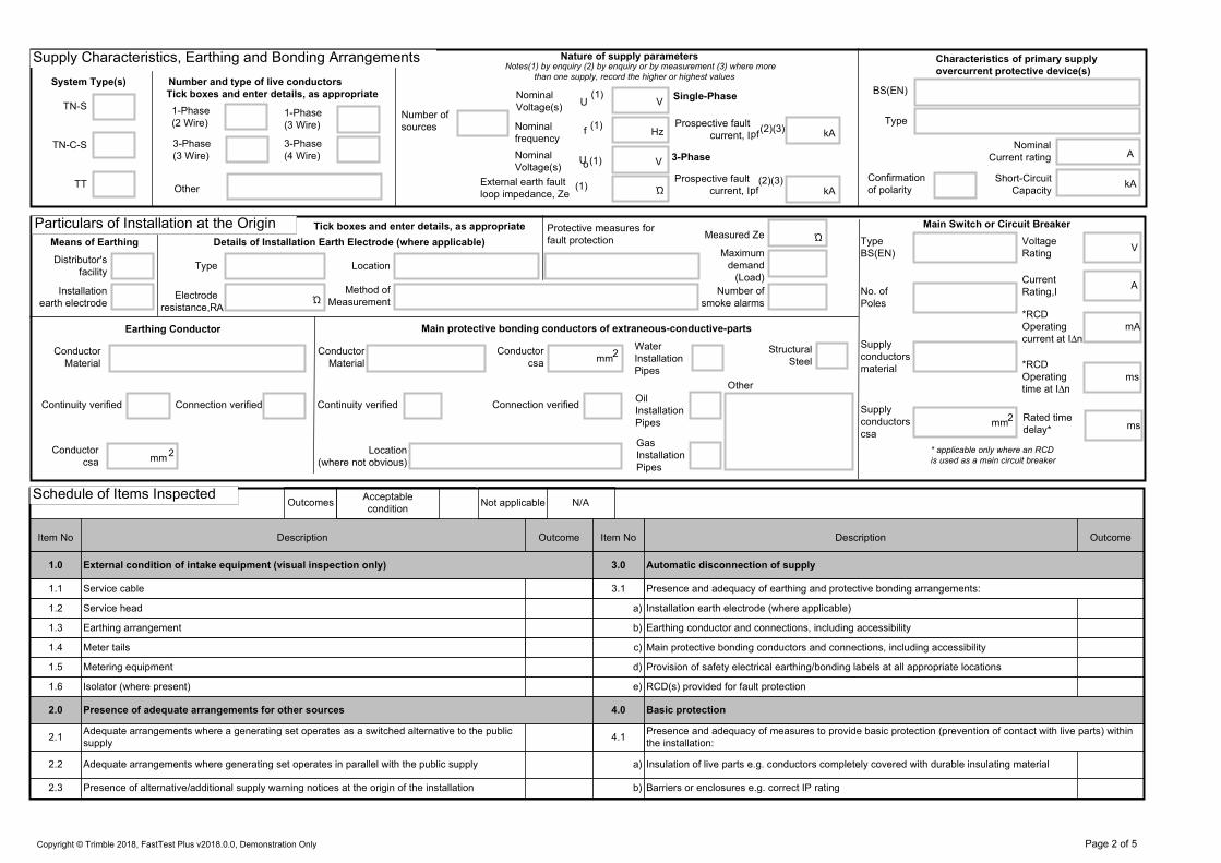
1.0 External condition of intake equipment (visual inspection only) 3.0 Automatic disconnection of supply
1.1 Service cable 3.1 Presence and adequacy of earthing and protective bonding arrangements:
1.2 Service head a) Installation earth electrode (where applicable)
1.3 Earthing arrangement b) Earthing conductor and connections, including accessibility
1.4 Meter tails c) Main protective bonding conductors and connections, including accessibility
1.5 Metering equipment d) Provision of safety electrical earthing/bonding labels at all appropriate locations
1.6 Isolator (where present) e) RCD(s) provided for fault protection
2.0 Presence of adequate arrangements for other sources 4.0 Basic protection
2.1Adequate arrangements where a generating set operates as a switched alternative to the public
supply4.1
Presence and adequacy of measures to provide basic protection (prevention of contact with live parts) within
the installation:
2.2 Adequate arrangements where generating set operates in parallel with the public supply a) Insulation of live parts e.g. conductors completely covered with durable insulating material
2.3 Presence of alternative/additional supply warning notices at the origin of the installation b) Barriers or enclosures e.g. correct IP rating
Supply Characteristics, Earthing and Bonding Arrang
Particulars of Installation at the Or
Schedule of Items Inspecte
Page 2 of 5Copyright © Trimble 2018, FastTest Plus v2018.0.0, Demonstration Only
Supply Characteristics, Earthing and Bonding Arrangements
Particulars of Installation at the Origin
Schedule of Items Inspected

Description Outcome
Acceptable condition Not applicable
Item No
N/A
Description OutcomeItem No
Outcomes
5.0 Additional protection 8.3Segregation/separation of Band I (ELV) and Band II (LV) circuits, and electrical and non-
electrical services
5.1 Presence and effectiveness of additional protection methods: 8.4 Cables correctly erected and supported throughout, with protection against abrasion
a) RCD(s) not exceeding 30 mA operating current 8.5 Provision of fire barriers, and sealing arrangements where necessary
b) Supplementary bonding 8.6 Non-sheathed cables enclosed throughout in conduit, ducting or trunking
6.0 Other methods of protection 8.7 Conductors correctly identified by colour, lettering or numbering
6.1 Presence and effectiveness of methods which give both basic and fault protection: 8.8 Presence, adequacy and correct termination of protective conductors
a) SELV system including the source and associated circuits 8.9 Cables and conductors correctly connected, enclosed and with no undue mechanical strain
b) PELV system including the source and associated circuits 8.10 No basic insulation of a conductor visible outside enclosure
c) Double or reinforced insulation i.e. Class II or equivalent equipment and associated circuits 8.11 Single-pole devices for switching or protection in line conductors only
d) Electrical separation for one item of equipment e.g. shaver supply unit 8.12 Accessories not damaged, securely fixed, correctly connected, suitable for external influences
7.0 Consumer unit(s)/distribution board(s) 8.13Cables concealed under floors, above ceilings or in walls/partitions, adequately protected
against damage
7.1 Adequacy of access and working space for items of electrical equipment including switchgear 8.14 Cables installed in walls or partitions, installed in prescribed zones
7.2 Components are suitable according to assembly manufacturer's instructions or literature 8.15 Provision of additional protection by RCD not exceeding 30 mA for:
7.3 Presence of linked main switch(es) a) - all socket-outlets with a rated current not exceeding 32 A
7.4 Isolators, for every circuit or group of circuits and all items of equipment b) - supplies to mobile equipment with a current rating not exceeding 32 A for use outdoors
7.5 Suitability of enclosure(s) for IP and fire ratings c) - cables concealed in walls/partitions at a depth of less than 50 mm
7.6 Protection against mechanical damage where cables enter equipment d) - cables concealed in walls/partitions containing metal parts regardless of depth
7.7Confirmation that ALL conductor connections are correctly located in terminals and are tight and
securee) - final circuits supplying luminaires within domestic (household) premises
7.8 Avoidance of heating effects where cables enter ferromagnetic enclosures e.g. steel 8.16 Presence of appropriate devices for isolation and switching correctly located including:
7.9Selection of correct type and ratings of circuit protective devices for overcurrent and fault
protectiona) Means of switching off for mechanical maintenance
7.10 Confirmation overvoltage protection (SPDs) provided where specified b) Emergency switches
7.11 Indication that SPDs continued functionality confirmed c) Functional switches, for control of parts of the installation and current-using equipment
7.12 Adequacy of AFDD(s) where present 9.0 Current-using equipment (permanently connected)
7.13 Presence of appropriate circuit charts, warning and other notices: 9.1 Suitability of equipment in terms of IP and fire ratings
a) Provision of circuit charts/schedules or equivalent forms of information 9.2 Enclosure not damaged/deteriorated so as to impair safety
b)Warning notice of method of isolation where live parts not capable of being isolated by a single
device9.3 Suitability for the environment and external influences
c) Periodic inspection and testing notice 9.4 Security of fixing
d) RCD six-monthly test notice where required 9.5 Cable entry holes in ceiling above luminaires, sized or sealed so as to restrict the spread of fire
e) AFDD six-monthly test notice where present 9.6 Recessed luminaires (downlighters):
f) Warning notice of non-standard (mixed) colours of conductors present a) Correct type of lamps fitted
7.14 Presence of labels to indicate the purpose of switchgear and protective devices b) Installed to minimise build-up of heat
8.0 Circuits 9.7 Adequacy of working space/accessibility to equipment
8.1Adequacy of conductors for current-carrying capacity with regard to type and nature of the
installation
8.2 Cable installation methods suitable for the location(s) and external influences
Schedule of Items Inspected
Page 3 of 5Copyright © Trimble 2018, FastTest Plus v2018.0.0, Demonstration Only
Schedule of Items Inspected

Description Outcome
Acceptable condition Not applicable
Item No
N/A
Description OutcomeItem No
Outcomes
Name:
Signature:
Date:
10.0 Location(s) containing a bath or shower 10.3 Shaver sockets comply with BS EN 61558-2-5
10.1 Additional protection by RCD not exceeding 30 mA for: 10.4Presence of supplementary protective equipotential bonding unless not required by BS 7671:
2018
a) - low voltage circuits serving the location 10.5 Low voltage (e.g. 230 volts) socket-outlets sited at least 3 m from Zone 1
b) - low voltage circuits passing through Zone 1 and/or Zone 2 not serving the location 10.6 Suitability of equipment for external influences for installed location in terms of IP rating
10.2 Where used as a protective measure, requirements for SELV or PELV are met 10.7 Suitability of equipment for installation in a particular zone
11.0 Other special installations or locations
11.1 List below any other special installations or locations which are part of the installation to be verified, and confirm that the additional requirements of the particulars of the installation are fulfilled
Schedule of Items Inspecte
Inspected By
Page 4 of 5Copyright © Trimble 2018, FastTest Plus v2018.0.0, Demonstration Only
Schedule of Items Inspected
Inspected By

CircuitNumber&
Phase
Circuit Designation
TypeofWiring
ReferenceMethod
Numberof
PointsServed
CircuitConductors
CSA
2
Live
2
CPC
Max.Disconnection
TimePerm
itted
byBS7671
Overcurrent Protective Device RCD
BS(EN)
TypeNo.
Rating
Capacity
Operating
CurrentI
n
Maxzsperm
ittedby
BS7671
Circuit Impedances ( )
Ring Final circuits only
(measured end to end)
r
Line
r
Neutral
r
CPC
1 n 2
Insulation Resistance
Line\Line
Line\Neutral
Line\Earth
Neutral\Earth
Polarity
RCD
All circuits (at least
one column to be
completed)
R + R21 2
R
A kA mA MΩ MΩ MΩ MΩmm mm ms
Location of
Consumer Unit(s)
Designation
Consumer Unit(s)kA
Prospective fault current
at Consumer Unit(s)
MultifunctionalInsulation
resistanceContinuity
Earth Fault loop
impedanceRCD
Earth electrode
resistance
Confirmation of
Supply polarity
Testbutton
operation
AFDDTestButton
Operation
AFDD
Maximummeasured
earthfaultloop
impedence
TestVoltage
Operatingtime
atIn
Supplementary
conductors
Page 5 of 5
Test Instruments
Circuit Details Test Results
Copyright © Trimble 2018, FastTest Plus v2018.0.0, Demonstration Only
DOMESTIC ELECTRICAL INSTALLATION CERTIFICATE
Circuit Details Test Results
Test Instruments
DOMESTIC ELECTRICAL INSTALLATION CERTIFICATE

Measured operating time
at l
I certify that the work covered by the certificate does not impair the safety of the existing installation and the work has been designed, constructed, inspected and
tested in accordance with BS 7671: (IET Wiring Regulations) amended to and that to the best of my knowledge and belief at the time of
my inspection complied with BS 7671 except as detailed in PART 1 above.
n
nms
s
4. Description of minor works
2. Date minor works completed
5. Details of departures if any from BS 7671:2018 for the circuit altered or extended (Regulations 120.3, 133.1.3, 133.5)
RCD operation:
Rated residual operating
current (l )
Satisfactory test button
operation
1. System earthing arrangement TT
DB Reference No.
TN-S
Circuit No.
Conductor sizes:
3. Presence of adequate main protective conductors
TN-C-S2. Earth fault loop impedance at distribution board
(Zdb) supplying the final circuit
mm2 2
Ω
DB location and type
A
Protective conductor continuity
MΩ mAR1 + R2 Ω
or R2 Ω
Continuity of ring final circuit conductors
ΩL/L
Ω
cpc/cpc
MΩ
Earth fault loop impedance Zs ΩΩ
cpc
Rating
Live
1. Details of Client
6. Comments on (including any defects observed in) the existing installation (Regulation 644.1.2)
Earthing conductor
Main protective bonding conductors to Water Gas
N/N
Insulation resistance
Live-Earth
Polarity satisfactory
Live-Live
Oil Structural steel
Circuit description
Circuit overcurrent
protective deviceBS (EN) Type
Other
mm
To be used only for minor electrical work which does not include the provision of a new circuit.
3. Location / Address
AFDD manual test satisfactory
Method of fault protection
Name
Signature
Position
Date
For and on behalf of
Address and Postcode
Name
Date
Position
Signature
The results of the inspection and testing
reviewed by the Qualified Supervisor
Other
ContinuityRCD
Insulation resistance
Earth fault loop
impedance
Agreed limitations, if any on the inspection and testing
Test instruments (serial numbers) used:
ΩMax Zs permitted by BS 7671
Where the method of fault protection is ADS insert
maximum disconnection time permitted by BS7671
Multi-function
Risk Assessment
attached
PART 1:Description of Minor Works
PART 3: Circuit details
Page 1 of 1Copyright © Trimble 2018, FastTest Plus v2018.0.0, Demonstration Only
PART 5: Declaration
PART 2: Presence and adequacy of installation earthing and bonding arrangements (Regulation 132.16)
PART 4: Test results for the circuit altered or extended (where relevant and practicable)
2018
Registration
No.
Branch No.
(If applicable)
MINOR ELECTRICAL INSTALLATION
WORKS CERTIFICATE
PART 1:Description of Minor Works
PART 2: Presence and adequacy of installation earthing and bonding arrangements (Regulation 132.16)
PART 3: Circuit details
PART 4: Test results for the circuit altered or extended (where relevant and practicable)
PART 5: Declaration

Where the overall assessment of the suitability of the installation for continued use above is stated as , recommend that any observations classified as
'Danger present' (code C1) or 'Potentially dangerous' (code C2) are acted upon as a matter of urgency.
Investigation without delay is recommended for observations identified as 'further investigation required' (code FI).
Observation classified as 'Improvement recommended' (code C3) should be given due consideration.
Subject to the necessary remedial action being taken recommend that the installation is further inspected and tested by
This inspection and testing detailed in this report and accompanying schedules have been carried out in accordance with BS7671:2018 (IET Wiring Regulations) as amended
to
, being the person(s) responsible for the inspection and testing of the electrical installation (as indicated by signatures below), particulars of
which are described above, having exercised reasonable skill and care when carrying out the inspection and testing, hereby declare that the
information in this report, including the observations and attached schedules, provides an accurate assessment of the condition of the electrical
installation taking into account the stated extent and limitations in section D of this report.
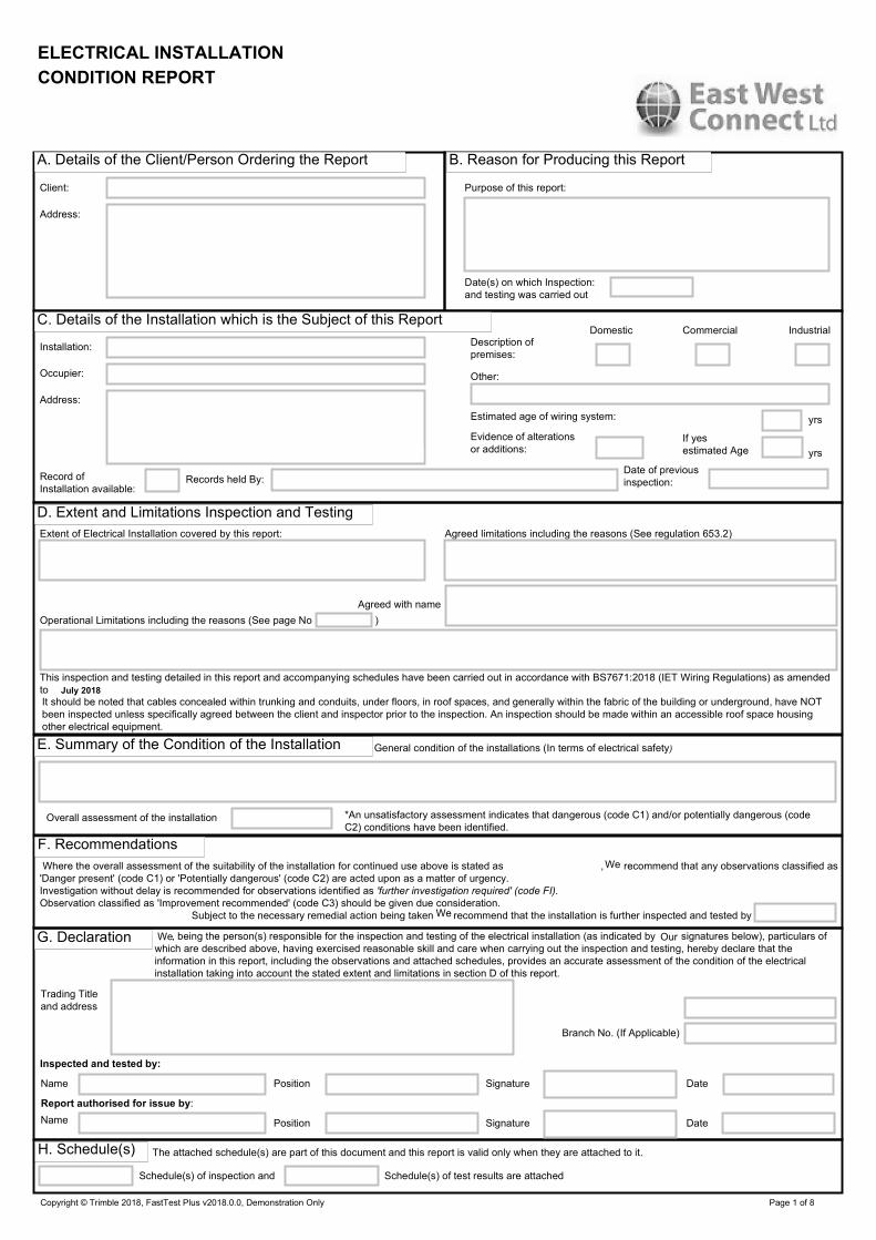
Extent of Electrical Installation covered by this report: Agreed limitations including the reasons (See regulation 653.2)
Operational Limitations including the reasons (See page No )
Agreed with name
Client:
Address:
Purpose of this report:
Date(s) on which Inspection:
and testing was carried out
General condition of the installations (In terms of electrical safety)
Overall assessment of the installation *An unsatisfactory assessment indicates that dangerous (code C1) and/or potentially dangerous (code
C2) conditions have been identified.
DomesticDescription of
premises:
Records held By:Record of
Installation available:
Date of previous
inspection:
Evidence of alterations
or additions:
Other:
IndustrialCommercial
Estimated age of wiring system:
yrs
yrs
If yes
estimated Age
Address:
Installation:
Trading Title
and address
Inspected and tested by:
Schedule(s) of inspection and Schedule(s) of test results are attached
Report authorised for issue by:
SignatureName Position Date
DatePosition SignatureName
The attached schedule(s) are part of this document and this report is valid only when they are attached to it.
It should be noted that cables concealed within trunking and conduits, under floors, in roof spaces, and generally within the fabric of the building or underground, have NOT
been inspected unless specifically agreed between the client and inspector prior to the inspection. An inspection should be made within an accessible roof space housing
other electrical equipment.
Branch No. (If Applicable)
Occupier:
Page 1 of 7Copyright © Trimble 2018, FastTest Plus v2018.0.0, Demonstration Only
D. Extent and Limitations Inspection and Testing
A. Details of the Client/Person Ordering the Report B. Reason for Producing this Report
E. Summary of the Condition of the Installation
F. RecommendationsWe
We
C. Details of the Installation which is the Subject of this Report
H. Schedule(s)
OurWe
July 2018
G. Declaration
ELECTRICAL INSTALLATION
CONDITION REPORT
ELECTRICAL INSTALLATION
CONDITION REPORT
A. Details of the Client/Person Ordering the Report B. Reason for Producing this Report
C. Details of the Installation which is the Subject of this Report
D. Extent and Limitations Inspection and Testing
E. Summary of the Condition of the Installation
F. Recommendations
G. Declaration
H. Schedule(s)

One of the following codes, as appropriate, has been allocated to each of the observations made above to indicate to the person(s) responsible for the installation the
degree of urgency for remedial action.
Nominal
current rating
Type
BS(EN)
Supply protective deviceNature of Supply Parameters
2-Phase
(3 wire)
1-Phase
(2 wire)
a.c.
Number and Type of Live Conductors
IT
TT
TN-C
TN-C-S
TN-S
Earthing
Arrangements
3-Phase
(3 wire)
Short circuit
capacity
d.c.
3
Wire
Other
2
Wire
Other
Means of earthing
Distributor's
facility
Installation
earth electrode
Type (e.g. rod(s),
tape etc.)
Details of installation Earth Electrode (where applicable)
Resistance to
EarthΩ
Location
Method of
measurement
Earthing
Conductor
Main protective
bonding conductors
Material
Material
csa
csa
mm
mm
2
2
Continuity Verified
Continuity Verified
Bonding of Incoming Service
Water installation
pipes
Gas installation
pipes
Lightning
protection
Oil installation
pipes
Structural
Steel
Other incoming
service(s)
Please State
Maximum Demand (Load)
Protective measure(s) against electric shock
Location
Type BS(EN)
Supply
Conductors
material
No of poles
Supply
Conductors
csa
Current
rating
Fuse/Device
rating or setting
Voltage
rating
A
A
V
if RCD main switch
mA
ms
ms
3-Phase
(4 wire)
Rated residual
operation current,
I n
Rated time delay
RCD Operating
time at, I n
Confirmation of supply polarity
Tick boxes and enter details as applicable
The following observations are madeNo remedial action is required.
Referring to the attached schedule(s) of Inspection and Test Results, and subject to the limitations specified at the Extent and Limitations of the Inspection and testing section.
Item No CodeObservations
kA
A
1-Phase
(3 wire)
mm2
(Note: (1) by enquiry, (2) by enquiry or
by measurement)
Number of
supplies
Ω(2)
ZeExternal loop
impedance
Prospective
fault currentlpf (2) kA
Hz(1)
fNominal
frequency
Nominal
VoltageU 0 V
VUNominal
Voltage
(1)
(1)
C1 - Danger present. Risk of injury. Immediate remedial action required
C2 - Potentially dangerous - urgent remedial action required
C3 - Improvement recommended
FI - Further investigation required without delay
Connection Verified
Connection Verified
I. Supply Characteristics and Earthing Arrangements
J. Particulars of Installation Referred to in the Report
Main Protective Conductors
Main Switch / Switch-Fuse / Circuit-Breaker / RCD
K. Observations
Page 2 of 7Copyright © Trimble 2018, FastTest Plus v2018.0.0, Demonstration Only
I. Supply Characteristics and Earthing Arrangements
J. Particulars of Installation Referred to in the Report
Main Protective Conductors
Main Switch / Switch-Fuse / Circuit-Breaker / RCD

N/AOutcomesAcceptable
condition
Unacceptable
condition
State C1
or C2
Improvement
recommended
State
C3
Not
verifiedN/V Limitation LIM
tick
Note: this form is suitable for many types of smaller installations not exclusively domestic.
Not applicable
Item No Description Outcome Comments
1.0 External condition of intake equipment (visual inspection only)
1.1 Service cable
1.2 Service head
1.3 Earthing arrangement
1.4 Meter tails
1.5 Metering equipment
1.6 Isolator (where present)
2.0 Presence of adequate arrangements for other sources
2.1 Presence of alternative/additional supply warning notices at the origin of the installation
3.0 Earthing and bonding arrangements
3.1 Presence and condition of distributor's earthing arrangement
3.2 Presence and condition of earth electrode connection, where appropriate
3.3 Confirmation of earthing conductor size
3.4 Accessibility and condition of earthing conductor at Main Earthing Terminal (MET)
3.5 Confirmation of main protective bonding conductor sizes
3.6 Condition and accessibility of main protective bonding conductor connections
3.7 Condition and accessibility of other protective bonding connections
3.8 Provision of earthing and bonding labels at all appropriate locations
4.0 Consumer unit(s)/ Distribution board(s)
4.1 Adequacy of working space/accessibility to consumer unit/ distribution board
4.2 Security of fixing
4.3 Condition of enclosure(s) in terms of IP rating
4.4 Condition of enclosure(s) in terms of fire rating
4.5 Enclosure not damaged/deteriorated so as to impair safety
4.6 Presence of linked main switch
4.7 Operation of main switch(es) (functional check)
4.8 Operation of main switch (functional), main switch capable of being secured in the OFF position
4.9 Manual operation of circuit breakers and RCDs to prove disconnection (functional check)
4.10 Correct identification of circuits and protective devices
4.11 Presence of required charts and labels:
4.11.1 Provision of diagram, chart, table or equivalent forms of information
4.11.2Warning notice of durable material indicating there are live parts which are not capable of being isolated by a
single device
4.11.3 Periodic inspection notice positioned at or near the origin of the installation
4.11.4 Presence of RCD six-monthly test notice at or near consumer unit/distribution board
4.11.5 Presence of non-standard (mixed) cable colour warning notice at or near consumer unit/distribution board
4.11.6 Presence of other required labelling provided
4.12Compatibility of protective device(s), base(s) and other components; correct type and rating (no signs of
unacceptable thermal damage,arcing or overheating)
4.13 Single-pole switching or protective devices in the line conductors only
4.14 Protection against mechanical damage where cables enter consumer unit/ distribution board
4.15 Protection against electromagnetic effects where cables enter metallic consumer unit enclosure
4.16 RCDs provided for fault protection - includes RCBOs
4.17 RCDs provided for additional protection includes RCBOs
4.18 Confirmation of indication that SPD is functional
4.19 Operation/adequacy of AFDD(s) where present
4.20Confirmation that conductor connections, including connections to busbars, are correctly located in terminals
and are tight and secure
4.21 Adequate arrangements where a generating set operates as a switched alternative to the public supply
4.22 Adequate arrangements where a generating set operates in parallel with the public supply
Further
investigationFI
CONDITION REPORT INSPECTION SCHEDULE FOR DOMESTIC AND
SIMILAR PREMISES WITH UP TO 100A SUPPLY
Page 3 of 7Copyright © Trimble 2018, FastTest Plus v2018.0.0, Demonstration Only
CONDITION REPORT INSPECTION SCHEDULE FOR DOMESTIC ANDSIMILAR PREMISES WITH UP TO 100A SUPPLY

N/A
Item No Description Outcome Comments
5.0 Distribution/final circuits
5.1 Identification of conductors
5.2 Cables correctly supported throughout
5.3 Condition of insulation of live parts
5.4Non-sheathed live conductors protected by enclosure in conduit, ducting or trunking (including confirmation of
the integrity of conduit and trunking systems)
5.5 Adequacy of cables for current-carrying capacity with regard to the type and nature of installation
5.6 Protective devices, type and rated current are suitable for fault protection
5.7 Presence and adequacy of circuit protective conductors
5.8 Co-ordination between conductors and overload protection devices
5.9 Wiring system(s) appropriate for the type and nature of the installation and external influences
5.10 Cables adequately protected against mechanical damage and abrasion
5.11 Provision of additional protection by 30 mA RCD for*:
5.11.1 - all socket-outlets with a rated current not exceeding 32 A
5.11.2 - mobile equipment not exceeding a rating of 32 A for use outdoors
5.11.3 - cables concealed in walls/partitions at a depth of less than 50 mm
5.11.4 - cables concealed in walls/partitions containing metal parts regardless of depth
5.11.5 - all AC final circuits supplying luminaires within domestic household premises
*Note: Older installations designed prior to BS 7671:2018 may not have been provided with RCDs for additional protection.
5.12 Provision of fire barriers, sealing arrangements and protection against thermal effects
5.13 Band II cables segregated/separated from Band I cables
5.14 Cables segregated/separated from communications cabling
5.15 Cables segregated/separated from non-electrical services
5.16 Termination of cables at enclosures:
5.16.1 Connections soundly made and under no undue strain
5.16.2 No basic insulation of a conductor visible outside enclosure
5.16.3 Connection of live conductors adequately enclosed
5.16.4 Adequately connected at point of entry to enclosure
5.17 Condition of accessories including socket-outlets, switches and joint boxes is satisfactory
5.18 Suitability of accessories for external influences
5.19 Adequacy of working space/accessibility to equipment
5.20 Single-pole switching or protective devices in line conductors only
6.0 Isolation and switching
6.1 In general:
6.1.1 Presence and condition of appropriate devices
6.1.2 Correct operation verified
6.2 For isolation and switching for mechanical maintenance only:
6.2.1 Capable of being secured in the OFF position where appropriate
6.2.2 Acceptable location (local/remote)
6.2.3 Clearly identified by position and/or durable marking(s)
6.3 For isolation only:
6.3.1 Warning label(s) posted in situations where live parts cannot be isolated by the operation of a single device
7.0 Current-using equipment (permanently connected)
7.1 Condition of equipment in terms of IP rating
7.2 Equipment does not constitute a fire hazard
7.3 Enclosure not damaged/deteriorated so as to impair safety
7.4 Suitability for the environment and external influences
7.5 Security of fixing
7.6 Cable entry holes in ceiling above luminaires sized or sealed so as to restrict the spread of fire
List number and location of luminaires inspected in section 9
Note: this form is suitable for many types of smaller installations not exclusively domestic.
OutcomesAcceptable
condition
Unacceptable
condition
State C1
or C2
Improvement
recommended
State
C3
Not
verifiedN/V Limitation LIM Not applicable
Further
investigationFI
CONDITION REPORT INSPECTION SCHEDULE FOR DOMESTIC AND
SIMILAR PREMISES WITH UP TO 100A SUPPLY CONTINUED
Copyright © Trimble 2018, FastTest Plus v2018.0.0, Demonstration Only Page 4 of 7
CONDITION REPORT INSPECTION SCHEDULE FOR DOMESTIC ANDSIMILAR PREMISES WITH UP TO 100A SUPPLY CONTINUED

N/A
Date:
Signature:
Name:
Note: this form is suitable for many types of smaller installations not exclusively domestic.
OutcomesAcceptable
condition
Unacceptable
condition
State C1
or C2
Improvement
recommended
State
C3
Further
investigationFI
Not
verifiedN/V Limitation LIM Not applicable
Item No Description Outcome Comments
7.7 Recessed luminaires (downlighters):
7.7.1 Correct type of lamps fitted
7.7.2 Installed to minimise build-up of heat
7.7.3 No signs of overheating to surrounding building fabric
7.7.4 No signs of overheating to conductors/terminations
8.0 Location(s) containing a bath or shower
8.1 Additional protection by RCD not exceeding 30mA for:
8.1.1 - low voltage circuits serving the location
8.1.2 - low voltage circuits passing through Zone 1 and Zone 2 not serving the location
8.2 Where used as a protective measure, requirements for SELV or PELV are met
8.3 Shaver sockets comply with BS EN 61558-2-5 (formerly BS 3535)
8.4 Presence of supplementary bonding conductors unless not required by BS 7671: 2018
8.5 Low voltage (e.g. 230 volts) socket-outlets sited at least 3 m from Zone 1
8.6 Suitability of equipment for external influences for installed location in terms of IP rating
8.7 Suitability of equipment for installation in a particular zone
9.0 Other special installations or locations
List all other special installations or locations present, if any. (Record separately the results of particular inspections applied).
Inspected By
Page 5 of 7Copyright © Trimble 2018, FastTest Plus v2018.0.0, Demonstration Only
CONDITION REPORT INSPECTION SCHEDULE FOR DOMESTIC AND
SIMILAR PREMISES WITH UP TO 100A SUPPLY CONTINUED
CONDITION REPORT INSPECTION SCHEDULE FOR DOMESTIC ANDSIMILAR PREMISES WITH UP TO 100A SUPPLY CONTINUED
Inspected By
Max
perm
itte
d
dis
con
ne
ctio
n
tim
es
(s)
Live
mm 22
Supply to
distribution
board is from:
No of phases
TO BE COMPLETED IN EVERY CASE ONLY TO BE COMPLETED IF THE DISTRIBUTION BOARD IS NOT CONNECTED DIRECTLY TO THE ORIGIN
OF THE INSTALLATION
Overcurrent protective device for the distribution circuit
Associated RCD (if any)
BS(EN)
RCD No of
Poles
RCD Rating
A B C D E F G H O
PVC/PVC
cables
PVCcables
in
metallic
conduit
PVCcables
in
non-metallic
conduit
PVCcables
in
metallic
trunking
PVCcables
in
non-metallic
trunking
PVC/SWA
cables
XLPE/SWA
cables
Mineral insulated
cablesOther
Nominal Voltage
Type BS(EN) Rating
Maxim
um
perm
itte
dZ
s
Cir
cuit
nu
mb
er
and
phase
Circuit designation
Type
of
wirin
g
Refe
rence
meth
od
No
of
po
ints
serv
ed
Circuit
conductors csa
cpc
mm
Overcurrent protective
deviceRCD
Type
Ratin
g(A
)
Sho
rtcircu
it
ca
pa
city
(kA
)
Ope
rating
curr
ent
(In)
BS(EN)
A
V
mA
Location of
Distribution
Board
Distribution
board
designation
AFDD
Circuit Details
Wiring Code
SCHEDULE OF CIRCUIT DETAILS FOR THE INSTALLATION
Board Details
Page 6 of 7Copyright © Trimble 2018, FastTest Plus v2018.0.0, Demonstration Only
SCHEDULE OF CIRCUIT DETAILS FOR THE INSTALLATION
Board Details
Circuit Details
Wiring Code

ms
Rem
ark
s
see
co
ntin
uation
she
et
Maximum
measured
earth fault
loop
impedance
TEST INSTRUMENTS (SERIAL NUMBERS) USED
Circuit
number
and
phase
Circuit Impedances
Po
larity
(v)
Live/
Neutral
Ope
rating
tim
e
at
I
Insulation resistance
Live/
Earth
Te
stb
utt
on
op
era
tio
n
r1 (Line) rn (Neutral) r2 (cpc) (R1 + R2) (R2)
All circuits
(At least one
column
to be completed)Live/
Live
Earth/
Neutral
Date of
testing
Position
Name
Signature
IpfZs kA
Operating times of associated RCD (if any) At I n
Ring final circuits only
(measure end to end)
RCD
Phase sequence confirmed
(where appropriate)
Correct supply polarity confirmed
Insulation
resistance
Multi-
function
RCD
Earth fault
loop
impedance
Continuity Other
n(m
s)
Test
Voltage
AF
DD
Testbu
tto
n
opera
tio
n
Supplementary Conductors
TO BE COMPLETED IN EVERY CASE
ONLY TO BE COMPLETED IF THE DISTRIBUTION BOARD IS NOT CONNECTED
DIRECTLY TO THE ORIGIN OF THE INSTALLATION
SCHEDULE OF CIRCUIT TESTS FOR THE INSTALLATION
Board Tests
Circuit Tests
Tested By
Details of circuits and/or equipment vulnerable to damage when testing
Page 7 of 7Copyright © Trimble 2018, FastTest Plus v2018.0.0, Demonstration Only
SCHEDULE OF CIRCUIT TESTS FOR THE INSTALLATION
Board Tests
Details of circuits and/or equipment vulnerable to damageh t ti
Circuit Tests
Tested By
Where the overall assessment of the suitability of the installation for continued use above is stated as , recommend that any observations classified as
'Danger present' (code C1) or 'Potentially dangerous' (code C2) are acted upon as a matter of urgency.
Investigation without delay is recommended for observations identified as 'further investigation required' (code FI).
Observation classified as 'Improvement recommended' (code C3) should be given due consideration.
Subject to the necessary remedial action being taken recommend that the installation is further inspected and tested by
This inspection and testing detailed in this report and accompanying schedules have been carried out in accordance with BS7671:2018 (IET Wiring Regulations) as amended
to
, being the person(s) responsible for the inspection and testing of the electrical installation (as indicated by signatures below), particulars of
which are described above, having exercised reasonable skill and care when carrying out the inspection and testing, hereby declare that the
information in this report, including the observations and attached schedules, provides an accurate assessment of the condition of the electrical
installation taking into account the stated extent and limitations in section D of this report.
Extent of Electrical Installation covered by this report: Agreed limitations including the reasons (See regulation 653.2)
Operational Limitations including the reasons (See page No )
Agreed with name
Client:
Address:
Purpose of this report:
Date(s) on which Inspection:
and testing was carried out
General condition of the installations (In terms of electrical safety)
Overall assessment of the installation *An unsatisfactory assessment indicates that dangerous (code C1) and/or potentially dangerous (code
C2) conditions have been identified.
DomesticDescription of
premises:
Records held By:Record of
Installation available:
Date of previous
inspection:
Evidence of alterations
or additions:
Other:
IndustrialCommercial
Estimated age of wiring system:
yrs
yrs
If yes
estimated Age
Address:
Installation:
Trading Title
and address
Inspected and tested by:
Schedule(s) of inspection and Schedule(s) of test results are attached
Report authorised for issue by:
SignatureName Position Date
DatePosition SignatureName
The attached schedule(s) are part of this document and this report is valid only when they are attached to it.
It should be noted that cables concealed within trunking and conduits, under floors, in roof spaces, and generally within the fabric of the building or underground, have NOT
been inspected unless specifically agreed between the client and inspector prior to the inspection. An inspection should be made within an accessible roof space housing
other electrical equipment.
Branch No. (If Applicable)
Occupier:
Page 1 of 8Copyright © Trimble 2018, FastTest Plus v2018.0.0, Demonstration Only
D. Extent and Limitations Inspection and Testing
A. Details of the Client/Person Ordering the Report B. Reason for Producing this Report
E. Summary of the Condition of the Installation
F. RecommendationsWe
We
C. Details of the Installation which is the Subject of this Report
H. Schedule(s)
OurWe
July 2018
G. Declaration
ELECTRICAL INSTALLATION
CONDITION REPORT
ELECTRICAL INSTALLATION
CONDITION REPORT
A. Details of the Client/Person Ordering the Report B. Reason for Producing this Report
C. Details of the Installation which is the Subject of this Report
D. Extent and Limitations Inspection and Testing
E. Summary of the Condition of the Installation
F. Recommendations
G. Declaration
H. Schedule(s)

One of the following codes, as appropriate, has been allocated to each of the observations made above to indicate to the person(s) responsible for the installation the
degree of urgency for remedial action.
Nominal
current rating
Type
BS(EN)
Supply protective deviceNature of Supply Parameters
2-Phase
(3 wire)
1-Phase
(2 wire)
a.c.
Number and Type of Live Conductors
IT
TT
TN-C
TN-C-S
TN-S
Earthing
Arrangements
3-Phase
(3 wire)
Short circuit
capacity
d.c.
3
Wire
Other
2
Wire
Other
Means of earthing
Distributor's
facility
Installation
earth electrode
Type (e.g. rod(s),
tape etc.)
Details of installation Earth Electrode (where applicable)
Resistance to
EarthΩ
Location
Method of
measurement
Earthing
Conductor
Main protective
bonding conductors
Material
Material
csa
csa
mm
mm
2
2
Continuity Verified
Continuity Verified
Bonding of Incoming Service
Water installation
pipes
Gas installation
pipes
Lightning
protection
Oil installation
pipes
Structural
Steel
Other incoming
service(s)
Please State
Maximum Demand (Load)
Protective measure(s) against electric shock
Location
Type BS(EN)
Supply
Conductors
material
No of poles
Supply
Conductors
csa
Current
rating
Fuse/Device
rating or setting
Voltage
rating
A
A
V
if RCD main switch
mA
ms
ms
3-Phase
(4 wire)
Rated residual
operation current,
I n
Rated time delay
RCD Operating
time at, I n
Confirmation of supply polarity
Tick boxes and enter details as applicable
The following observations are madeNo remedial action is required.
Referring to the attached schedule(s) of Inspection and Test Results, and subject to the limitations specified at the Extent and Limitations of the Inspection and testing section.
Item No CodeObservations
kA
A
1-Phase
(3 wire)
mm2
(Note: (1) by enquiry, (2) by enquiry or
by measurement)
Number of
supplies
Ω(2)
ZeExternal loop
impedance
Prospective
fault currentlpf (2) kA
Hz(1)
fNominal
frequency
Nominal
VoltageU 0 V
VUNominal
Voltage
(1)
(1)
C1 - Danger present. Risk of injury. Immediate remedial action required
C2 - Potentially dangerous - urgent remedial action required
C3 - Improvement recommended
FI - Further investigation required without delay
Connection Verified
Connection Verified
I. Supply Characteristics and Earthing Arrangements
J. Particulars of Installation Referred to in the Report
Main Protective Conductors
Main Switch / Switch-Fuse / Circuit-Breaker / RCD
K. Observations
Page 2 of 8Copyright © Trimble 2018, FastTest Plus v2018.0.0, Demonstration Only
I. Supply Characteristics and Earthing Arrangements
J. Particulars of Installation Referred to in the Report
Main Protective Conductors
Main Switch / Switch-Fuse / Circuit-Breaker / RCD

N/A
Item No Description Outcome Comments
1.0 External condition of electrical intake equipment (visual inspection only)
1.1 Service cable
1.2 Service head
1.3 Earthing arrangement
1.4 Meter tails
1.5 Metering equipment
1.6 Isolator (where present)
Where inadequacies in intake equipment are encountered, it is recommended that the person ordering the report informs the appropriate authority.
2.0 Presence of adequate arrangements for parallel or switched alternative sources
2.1 Adequate arrangements where a generating set operates as a switched alternative to the public supply
2.2 Adequate arrangements where generating set operates in parallel with the public supply
2.3 Presence of alternative / additional supply warning notices at the origin of the installation
3.0 Automatic disconnection of supply
3.1 Main earthing and bonding arrangements:
3.1.1 Presence and condition of distributor's earthing arrangement
3.1.2 Presence and condition of earth electrode arrangement
3.1.3 Adequacy of earthing conductor size
3.1.4 Adequacy of earthing conductor connections
3.1.5 Accessibility of earthing conductor connections
3.1.6 Adequacy of main protective bonding conductor size(s)
3.1.7 Adequacy and location of main protective bonding conductor connections
3.1.8 Accessibility of main protective bonding connections
3.1.9 Accessibility/condition of other protective bonding connections
3.1.10 Provision of earthing/bonding labels at all appropriate locations
3.2 FELV:
3.2.1 (FELV) system shall either be a transformer with at least simple separation between windings
3.2.2Every plug, socket-outlet, luminaire supporting coupler (LSC), device for connecting a luminaire (DCL) and
cable coupler in a FELV system not interchangeable with those of other systems within the premises
4.0 Other methods of protection (where any of the methods listed below are employed, details should be provided on separate sheets)
4.1 Non-conducting location
4.2 Earth-free local equipotential bonding
4.3 Electrical separation
4.4 Double insulation
4.5 Reinforced insulation
5.0 Distribution equipment
5.1 Adequacy of working space/accessibility of equipment
5.2 Security of fixing
5.3 Condition of insulation of live parts
5.4 Adequacy/security of barriers
5.5 Condition of enclosure(s) in terms of IP rating
5.6 Condition of enclosure(s) in terms of fire rating
5.7 Enclosure not damaged/deteriorated so as to impair safety
5.8 Presence and effectiveness of obstacles
5.9 Presence of main switch(es), linked where required
5.10 Operation of main switch(es) (functional check)
5.11 Correct identification of circuit protective devices
5.12 Adequacy of protective devices for prospective fault current
5.13 RCD(s) provided for fault protection - includes RCBOs
5.14 RCD(s) provided for additional protection - includes RCBOs
5.15 RCD(s) provided for protection against fire - includes RCBOs
5.16 Manual operation of circuit-breakers and RCDs to prove disconnection
5.17 Confirmation that integral test button/switch causes RCD(S) to trip when operated (functional check)
OutcomesUnacceptable
condition
State
C3
Not
verifiedN/V Limitation LIM Not applicable
Further
investigationFI
Improvement
recommended
State C1
or C2
Acceptable
condition
CONDITION REPORT INSPECTION SCHEDULE FOR COMMERCIAL AND SIMILAR
PREMISES WITH GREATER THAN 100A SUPPLY
Page 3 of 8Copyright © Trimble 2018, FastTest Plus v2018.0.0, Demonstration Only
CONDITION REPORT INSPECTION SCHEDULE FOR COMMERCIAL AND SIMILARPREMISES WITH GREATER THAN 100A SUPPLY

N/A
Item No Description Outcome Comments
5.0 Distribution equipment (continued)
5.18 Presence of RCD six-monthly retest notice at or near equipment, where required
5.19 Presence of diagrams, charts or schedules at or near equipment, where required
5.20 Presence of non-standard (mixed) cable colour warning notices at or near equipment, where required
5.21 Presence of next inspection recommendation label
5.22 All other required labelling provided
5.23 Compatibility of protective device(s), base(s) and other components
5.24 Single-pole switching or protective devices in line conductors only
5.25 Protection against mechanical damage where cables enter equipment
5.26 Protection against electromagnetic effects where cables enter ferromagnetic enclosures
6.0 Distribution/final circuits
6.1 Identification of conductors
6.2 Cables correctly supported throughout their length
6.3 Condition of insulation of live parts
6.4 Non-sheathed cables protected by enclosures in conduit, ducting or trunking
6.5 Suitability of containment systems for continued use (including flexible conduit)
6.6 Cables correctly terminated in enclosures (indicate extent of sampling in Section D of report)
6.7 Indication of SPD(s) continued functionality confirmed
6.8 Adequacy of AFDD(s), where specified
6.9Confirmation that conductor connections, including connections to busbars are correctly located in terminals
and are tight and secure
6.10 Examination of cables for signs of unacceptable thermal and mechanical damage/deterioration
6.11 Adequacy of cables for current-carrying capacity with regard to the type and nature of installation
6.12 Adequacy of protective devices; type and rated current for fault protection
6.13 Presence and adequacy of circuit protective conductors
6.14 Co-ordination between conductors and overload protective devices
6.15 Cable installation methods/practices appropriate to the type and nature of installation and external influences
6.16 Cables where exposed to direct sunlight, of a suitable type or adequately protected against solar radiation
6.17 Cables adequately protected against damage and abrasion
6.18 Provision of additional protection by an RCD not exceeding 30 mA for:
6.18.1 - all socket-outlets with a rated current not exceeding 32 A, unless exempt
6.18.2 - supplies for mobile equipment with a rated current not exceeding 32 A for use outdoors
6.18.3 - cables concealed in walls/partitions at a depth of less than 50 mm
6.18.4 - cables concealed in walls/partitions containing metal parts regardless of depth
6.18.5 - circuits supplying luminaires within domestic (household) premises
Note: Older installations designed prior to BS 7671: 2018 may not have been provided with RCDs for additional protection.
6.19 Provision of fire barriers, sealing arrangements and protection against thermal effects
6.20 Band II cables segregated/separated from Band I cables
6.21 Cables segregated/separated from non-electrical services
6.22 Termination of cables at enclosures (identify numbers and locations of items inspected in Section D):
6.22.1 Connections under no undue strain
6.22.2 No basic insulation of a conductor, visible outside an enclosure
6.22.3 Connections of live conductors adequately enclosed
6.22.4 Adequacy of connection at point of entry to enclosure
6.23 Temperature rating of cable insulation adequate
6.24 Condition of accessories including socket-outlets, switches and joint boxes satisfactory
6.25 Suitability of accessories for external influences
6.26 Single-pole switching or protective devices in line conductors only
6.27 Adequacy of connections, including CPCs, within accessories and to fixed and stationary equipment
OutcomesAcceptable
condition
Unacceptable
condition
State C1
or C2
Improvement
recommended
State
C3
Not
verifiedN/V Limitation LIM Not applicable
Further
investigationFI
CONDITION REPORT INSPECTION SCHEDULE FOR COMMERCIAL AND SIMILAR
PREMISES WITH GREATER THAN 100A SUPPLY CONTINUED
Copyright © Trimble 2018, FastTest Plus v2018.0.0, Demonstration Only Page 4 of 8
CONDITION REPORT INSPECTION SCHEDULE FOR COMMERCIAL AND SIMILARPREMISES WITH GREATER THAN 100A SUPPLY CONTINUED

N/AN/AAcceptable
condition
Unacceptable
condition
State C1
or C2
Improvement
recommended
State
C3
Further
investigationFI
Not
verifiedN/V Limitation LIM
Item No Description Outcome Comments
7.0 Isolation and switching
7.1 Isolators:
7.1.1 Presence and condition of appropriate devices
7.1.2 Acceptable location (local/remote)
7.1.3 Capable of being secured in the OFF position
7.1.4 Correct operation verified
7.1.5 Clearly identified by position and/or durable markings
7.1.6 Warning label posted in situations where live parts cannot be isolated by the operation of a single device
7.2 Switching off for mechanical maintenance:
7.2.1 Presence and condition of appropriate devices
7.2.2 Acceptable location
7.2.3 Capable of being secured in the OFF position
7.2.4 Correct operation verified
7.2.5 Clearly identified by position and/or durable marking(s)
7.3 Emergency switching off/stopping:
7.3.1 Presence and condition of appropriate devices
7.3.2 Readily accessible for operation where danger might occur
7.3.3 Correct operation verified
7.4 Functional switching:
7.4.1 Presence and condition of appropriate devices
7.4.2 Correct operation (functionality) verified
8.0 Current-using equipment (permanently connected)
8.1 Condition of equipment in terms of IP rating
8.2 Equipment does not constitute a fire hazard
8.3 Enclosure not damaged/deteriorated so as to impair safety
8.4 Suitability for the environment and external influences
8.5 Security of fixing
8.6 Cable entry holes in ceiling above luminaires, sized or sealed so as to restrict the spread of fire
8.7 Recessed luminaires (e.g. downlighters):
8.7.1 Correct type of lamps fitted
8.7.2 Installed to minimise build-up of heat
8.7.3 No signs of overheating to surrounding building fabric
8.7.4 No signs of overheating to conductors/terminations
9.0 List all special installations or locations covered by this report
Not applicableOutcomesState
C3
Further
investigationFI
Not
verifiedN/V Limitation LIM Not applicable
CONDITION REPORT INSPECTION SCHEDULE FOR COMMERCIAL AND SIMILAR
PREMISES WITH GREATER THAN 100A SUPPLY CONTINUED
Copyright © Trimble 2018, FastTest Plus v2018.0.0, Demonstration Only Page 5 of 8
CONDITION REPORT INSPECTION SCHEDULE FOR COMMERCIAL AND SIMILARPREMISES WITH GREATER THAN 100A SUPPLY CONTINUED

Name:
Signature:
Date:
9.0 List all special installations or locations covered by this report cont...
CONDITION REPORT INSPECTION SCHEDULE FOR COMMERCIAL AND SIMILAR
PREMISES WITH GREATER THAN 100A SUPPLY CONTINUED
Copyright © Trimble 2018, FastTest Plus v2018.0.0, Demonstration Only
Inspected By
Page 6 of 8
CONDITION REPORT INSPECTION SCHEDULE FOR COMMERCIAL AND SIMILARPREMISES WITH GREATER THAN 100A SUPPLY CONTINUED
Inspected By

Max
perm
itte
d
dis
con
ne
ctio
n
tim
es
(s)
Live
mm 22
Supply to
distribution
board is from:
No of phases
TO BE COMPLETED IN EVERY CASE ONLY TO BE COMPLETED IF THE DISTRIBUTION BOARD IS NOT CONNECTED DIRECTLY TO THE ORIGIN
OF THE INSTALLATION
Overcurrent protective device for the distribution circuit
Associated RCD (if any)
BS(EN)
RCD No of
Poles
RCD Rating
A B C D E F G H O
PVC/PVC
cables
PVCcables
in
metallic
conduit
PVCcables
in
non-metallic
conduit
PVCcables
in
metallic
trunking
PVCcables
in
non-metallic
trunking
PVC/SWA
cables
XLPE/SWA
cables
Mineral insulated
cablesOther
Nominal Voltage
Type BS(EN) Rating
Maxim
um
perm
itte
dZ
s
Cir
cuit
nu
mb
er
and
phase
Circuit designation
Type
of
wirin
g
Refe
rence
meth
od
No
of
po
ints
serv
ed
Circuit
conductors csa
cpc
mm
Overcurrent protective
deviceRCD
Type
Ratin
g(A
)
Sho
rtcircu
it
ca
pa
city
(kA
)
Ope
rating
curr
ent
(In)
BS(EN)
A
V
mA
Location of
Distribution
Board
Distribution
board
designation
AFDD
Circuit Details
Wiring Code
SCHEDULE OF CIRCUIT DETAILS FOR THE INSTALLATION
Board Details
Page 7 of 8Copyright © Trimble 2018, FastTest Plus v2018.0.0, Demonstration Only
SCHEDULE OF CIRCUIT DETAILS FOR THE INSTALLATION
Board Details
Circuit Details
Wiring Code

ms
Rem
ark
s
see
co
ntin
uation
she
et
Maximum
measured
earth fault
loop
impedance
TEST INSTRUMENTS (SERIAL NUMBERS) USED
Circuit
number
and
phase
Circuit Impedances
Po
larity
(v)
Live/
Neutral
Ope
rating
tim
e
at
I
Insulation resistance
Live/
Earth
Te
stb
utt
on
op
era
tio
n
r1 (Line) rn (Neutral) r2 (cpc) (R1 + R2) (R2)
All circuits
(At least one
column
to be completed)Live/
Live
Earth/
Neutral
Date of
testing
Position
Name
Signature
IpfZs kA
Operating times of associated RCD (if any) At I n
Ring final circuits only
(measure end to end)
RCD
Phase sequence confirmed
(where appropriate)
Correct supply polarity confirmed
Insulation
resistance
Multi-
function
RCD
Earth fault
loop
impedance
Continuity Other
n(m
s)
Test
Voltage
AF
DD
Testbu
tto
n
opera
tio
n
Supplementary Conductors
TO BE COMPLETED IN EVERY CASE
ONLY TO BE COMPLETED IF THE DISTRIBUTION BOARD IS NOT CONNECTED
DIRECTLY TO THE ORIGIN OF THE INSTALLATION
SCHEDULE OF CIRCUIT TESTS FOR THE INSTALLATION
Board Tests
Circuit Tests
Tested By
Details of circuits and/or equipment vulnerable to damage when testing
Page 8 of 8Copyright © Trimble 2018, FastTest Plus v2018.0.0, Demonstration Only
SCHEDULE OF CIRCUIT TESTS FOR THE INSTALLATION
Board Tests
Details of circuits and/or equipment vulnerable to damageh t ti
Circuit Tests
Tested By

Issued in accordance with BS 5839-6 : 2017
Client :
Address : PostCode:
The System Is :
Address :New
ModificationExtent of the fire detection and
alarm system covered by this
certificate
PostCode:
System Grade : B C D E F System Category : PD1 PD2LD3LD2LD1
( See Note 1 ) A tick in the box indicates the inspection or test has been performed and the results are satisfactory
N/A indicates an inspection or test is not appropriate
Test buttons checked
All alarm warning
devices operate
Silencing system
checked
Simulated smoke
or aerosol test
Heat Test
Bedroom sound
level (Clause 13.2)
Dedicated circuit(s)
provided
Protective device
labelled
Audible and Visual
indication of mains
failure
Sound level test instrument used (See Note 2)
Model and Serial no.
Serial No. of associated
Electrical Installations Certificate
or Minor Electrical Installation
Works Certificate (See Note 1)
Tick boxes to indicate that the written information has been issued to the user
I/We the undersigned declare that the occupier* of the dwelling (or owner in the case of a house in multiple occupancy) has been
provided with written information about essential aspects of the operation and maintenance of the system, as follows :
Operation of the system Routine testing of the system Checking the system on
reoccupation of the
dwelling after a vacation etc.Action to be taken in the event of an
alarm signal
Servicing and maintenance of the system
(including intervals at which
any batteries should be replaced)
The need to keep clear space around all
detectors and manual call points
Avoidance of false alarms and action
in the event of a false alarm
Warning that apparent false alarm
from carbon monoxide detector may
not be false alarm
Special precautions relevant to any lithium
batteries used in the system
The need to avoid
contamination of detectors by
paint
As-fitted drawing
*In the case of a newly-built property and where the future occupier is unknown, the User Instructions
should be issued to the builder for onward transmission to the purchaser together with the related electrical safety certificate.
Date:Signature:
This certificate has been reviewed by the Qualified Supervisor:
Variations(if any)
The extent of liability of the signatory / signatories is limited to the work described above as the subject of this certificate.
Signature:
Name:
Date:
Name:
Trading title
Address :
PostCode:Branch No.
(if applicable)
Registration No.
(Essential information)
Note 1. The electrical safety aspects of the fire detection and alarm system must also be certified in accordance with BS 7671: 'Requirements for Electrical Installations' by issuing an electrical safety certificate
of a form which meets the requirments of BS 7671 such as a 'Domestic Electrical Installation Certifcate' or, where appropriate, a 'Minor Electrical Installation Works Certificate'.
Note 2. An instrument complying with BS EN 61672, Class 2, with slow response and A weighting (see clause 13.2), is suitable for measuring the sound level .
Note 3. This certificate may be required by an authority responsible for enforcement of fire safety legislation, such as the building control authority or housing authority. The recepient of this certificate might rely
on the certificate as evidence of compliance with legislation. Liability could arise on the part of any organisation or person that issues a certificate without due care in ensuring its validity.
I/We, being the person(s) responsible (as indicated by my/our signature(s) below), for the design, installation and commissioning of the fire alarm system,
particulars of which are set out above, CERTIFY that the said work for which I/We have been responsible complies to the best of My/our knowledge and belief with the
recommendations of BS 5839: Part 6 for the system described above, except for the variations, if any, stated below:
For the design, installation and commissioning of the system:
User
Certificate of Design, Installation and
Details of Approved
Page 1 of 1Copyright © Trimble 2018, FastTest Plus v2018.0.0, Demonstration Only
Details of the Fire Detection and Alarm
Description of System Grade and System
Commissioni
Details of
SYSTEM OF GRADE B, C, D, E, OR F IN A DWELLING
DETECTION AND ALARM COMMISSIONING OF A FIRE
CERTIFICATE OF DESIGN, INSTALLATION AND
Details of Client
Details of the Fire Detection and Alarm System
Description of System Grade and System Category
Commissioning
Certificate of Design, Installation and Commissioning
Details of Approved Contractor
CERTIFICATE OF DESIGN, INSTALLATION AND
DETECTION AND ALARM COMMISSIONING OF A FIRE
SYSTEM OF GRADE B, C, D, E, OR F IN A DWELLING
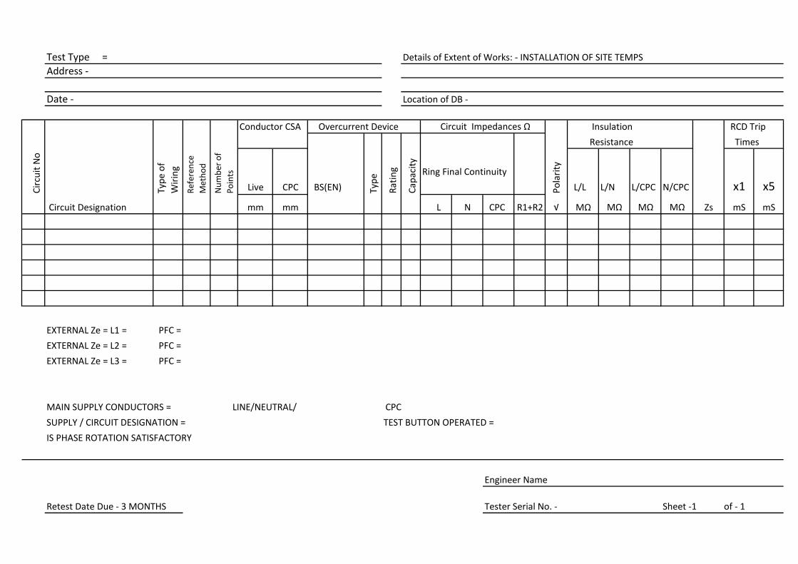
Test Type =
Address -
Date - Location of DB -
Conductor CSA Overcurrent Device Circuit Impedances Ω Insulation RCD Trip
Resistance Times Times
Cir
cuit
No
Typ
e o
f
Wir
ing
Ref
eren
ce
Met
ho
d
Nu
mb
er o
f
Po
ints
Live CPC BS(EN) Typ
e
Rat
ing
Cap
acit
y
Ring Final Continuity
Po
lari
ty
L/L L/N L/CPC N/CPC x1 x5
Circuit Designation mm mm L N CPC R1+R2 √ MΩ MΩ MΩ MΩ Zs mS mS
EXTERNAL Ze = L1 = PFC =
EXTERNAL Ze = L2 = PFC =
EXTERNAL Ze = L3 = PFC =
MAIN SUPPLY CONDUCTORS = LINE/NEUTRAL/ CPC
SUPPLY / CIRCUIT DESIGNATION = TEST BUTTON OPERATED =
IS PHASE ROTATION SATISFACTORY
Engineer Name
Retest Date Due - 3 MONTHS Tester Serial No. - Sheet -1 of - 1
Details of Extent of Works: - INSTALLATION OF SITE TEMPS
Related Documents