Tribhuvan University Institute of Engineering Pulchowk Campus Department of Civil Engineering Lalitpur, Nepal . Final Year Project Report On Earthquake Resistant Design of Apartment Building Submitted to Department of Civil Engineering IŶ the paƌtial fulfillŵeŶt of BaĐheloƌ’s Degƌee iŶ Ciǀil EŶgiŶeeƌiŶg Supervisor Er. Dinesh Gupta Submitted By: (067BCE016) Ashim Maharjan (067BCE019) Ashwin Poudel (067BCE021) Asmita Shrestha (067BCE023) Barsha Neupane (067BCE024) Bidhya Subedi (067BCE028) Biraj Adhikari August, 2014

Welcome message from author
This document is posted to help you gain knowledge. Please leave a comment to let me know what you think about it! Share it to your friends and learn new things together.
Transcript
Tribhuvan University
Institute of Engineering
Pulchowk Campus
Department of Civil Engineering
Lalitpur, Nepal
.
Final Year Project Report
On
Earthquake Resistant Design of
Apartment Building
Submitted to Department of Civil Engineering
I the pa tial fulfill e t of Ba helo ’s Deg ee i Ci il E gi ee i g
Supervisor
Er. Dinesh Gupta
Submitted By:
(067BCE016) Ashim Maharjan
(067BCE019) Ashwin Poudel
(067BCE021) Asmita Shrestha
(067BCE023) Barsha Neupane
(067BCE024) Bidhya Subedi
(067BCE028) Biraj Adhikari
August, 2014

Tribhuvan University
Institute of Engineering
Pulchowk Campus
Department of Civil Engineering
Lalitpur, Nepal
Final Year Project Report
On
Earthquake Resistant Design of
Apartment Building
Submitted To:
Department of Civil Engineering
Pulchowk Campus
Tribhuvan University
Institute of Engineering
Pulchowk Campus
Department of Civil Engineering
Lalitpur, Nepal
.
Certificate
This is to e tify that this p oje t o k e titled Earthquake Resistant Design of Apartment
Buildi g has been examined and it has been declared successful for the fulfillment of the academic
e ui e e t to a ds the o pletio of the Ba helo ’s Deg ee i Ci il E gineering.
------------------------- ------------------------ Dr. Jagat Kumar Shrestha Er. Siddharth Shankhar
External Examiner Internal Examiner
-------------------------
Er. Dinesh Gupta
Project Supervisor
-------------------------
Prof. Vishwa Nath Khanal
Head
Department of Civil Engineering

ACKNOWLEDGEMENT
We are highly indebted to all our respected instructors of IOE, Pulchowk Campus for their
exquisite remarks and precious guidance with which they guided us through every academic task
fo a ded y this i stitute i diffe e t e gi ee i g assig e ts a d tasks to oost the stude ts’ capability as a diligent engineer.
We are highly thankful to our project supervisor Er. Dinesh Gupta whose encouragement
and trendsetting guidance helped us understand this project better. His perpetual guidance and
willingness to share his vast knowledge made us undertake this project and its manifestations in
great depths and helped us complete the assigned project titled EARTHQUAKE RESISTANT DESIGN
OF APARTMENT BUILDING . This p oje t ould ’t ha e ee a su ess ithout his ki d suppo t, untiring efforts and encouragements in each and every task.
We would like express our gratitude to Campus Chief Dr. Arvinda Kumar Mishra and our
Head of the Department Vishwa Nath Khanal for their extended support.
Also, we are extremely thankful towards Prof. Dr. Prem Nath Maskey, Prof. Dr. Hikmat Raj
Joshi, Er. Nabin Chandra Sharma, Dr. Kamal Thapa, Er. Mukesh Kafle and Er. Sujan Tripathi who
laid the foundations on structure during B.E. courses through semesters first to eight. We would
certainly anticipate their kind comments on our project works on the basis of their long experiences
and professional knowledge.
We would not be able to stand out without basic foundation books written and published by
author. Dr. Gokarna Badahur Motra, Dr. Rajan Suwal and Suresh Hada for letting us acquainted
with the basics of structures. Finally, we would like to show appreciation to all the personalities who
supported us directly or indirectly in completion of project work and to prepare this wonderful
report. We would like to acknowledge each of our group members for their jovial understanding and
reinforcement.
(067BCE016) Ashim Maharjan
(067BCE019) Ashwin Poudel
(067BCE021) Asmita Shrestha
(067BCE023) Barsha Neupane
(067BCE024) Bidhya Subedi
(067BCE028) Biraj Adhikari
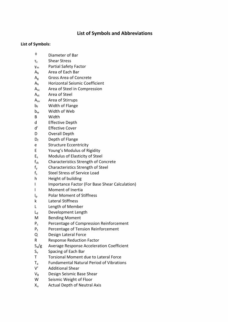
List of Symbols and Abbreviations
List of Symbols:
Diameter of Bar
τc Shear Stress
γm Partial Safety Factor
Ab Area of Each Bar
Ag Gross Area of Concrete
Ah Horizontal Seismic Coefficient
Asc Area of Steel in Compression
Ast Area of Steel
Asv Area of Stirrups
bf Width of Flange
bw Width of Web
B Width
d Effective Depth
d′ Effective Cover
D Overall Depth
Df Depth of Flange
e Structure Eccentricity
E You g’s Modulus of Rigidity
Es Modulus of Elasticity of Steel
fck Characteristics Strength of Concrete
fy Characteristics Strength of Steel
fs Steel Stress of Service Load
h Height of building
I Importance Factor (For Base Shear Calculation)
I Moment of Inertia
Ip Polar Moment of Stiffness
k Lateral Stiffness
L Length of Member
Ld Development Length
M Bending Moment
Pc Percentage of Compression Reinforcement
Pt Percentage of Tension Reinforcement
Q Design Lateral Force
R Response Reduction Factor
Sa/g Average Response Acceleration Coefficient
Sv Spacing of Each Bar
T Torsional Moment due to Lateral Force
Ta Fundamental Natural Period of Vibrations
V′ Additional Shear
VB Design Seismic Base Shear
W Seismic Weight of Floor
Xu Actual Depth of Neutral Axis
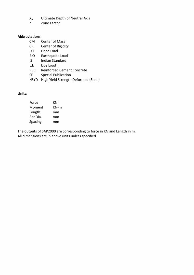
Xul Ultimate Depth of Neutral Axis
Z Zone Factor
Abbreviations:
CM Center of Mass
CR Center of Rigidity
D.L Dead Load
E.Q Earthquake Load
IS Indian Standard
L.L Live Load
RCC Reinforced Cement Concrete
SP Special Publication
HSYD High Yield Strength Deformed (Steel)
Units:
Force KN
Moment KN-m
Length mm
Bar Dia. mm
Spacing mm
The outputs of SAP2000 are corresponding to force in KN and Length in m.
All dimensions are in above units unless specified.
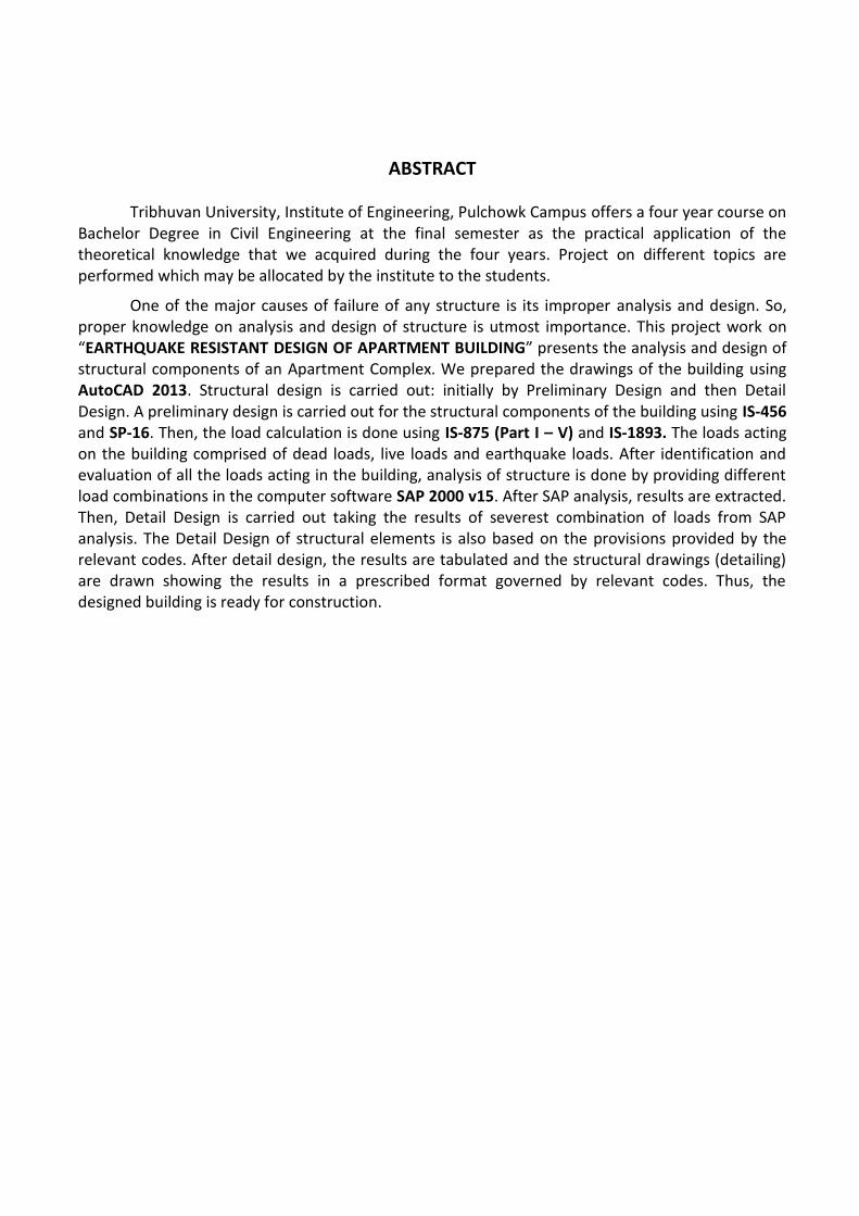
ABSTRACT
Tribhuvan University, Institute of Engineering, Pulchowk Campus offers a four year course on
Bachelor Degree in Civil Engineering at the final semester as the practical application of the
theoretical knowledge that we acquired during the four years. Project on different topics are
performed which may be allocated by the institute to the students.
One of the major causes of failure of any structure is its improper analysis and design. So,
proper knowledge on analysis and design of structure is utmost importance. This project work on
EARTHQUAKE RESISTANT DESIGN OF APARTMENT BUILDING p ese ts the analysis and design of
structural components of an Apartment Complex. We prepared the drawings of the building using
AutoCAD 2013. Structural design is carried out: initially by Preliminary Design and then Detail
Design. A preliminary design is carried out for the structural components of the building using IS-456
and SP-16. Then, the load calculation is done using IS-875 (Part I – V) and IS-1893. The loads acting
on the building comprised of dead loads, live loads and earthquake loads. After identification and
evaluation of all the loads acting in the building, analysis of structure is done by providing different
load combinations in the computer software SAP 2000 v15. After SAP analysis, results are extracted.
Then, Detail Design is carried out taking the results of severest combination of loads from SAP
analysis. The Detail Design of structural elements is also based on the provisions provided by the
relevant codes. After detail design, the results are tabulated and the structural drawings (detailing)
are drawn showing the results in a prescribed format governed by relevant codes. Thus, the
designed building is ready for construction.
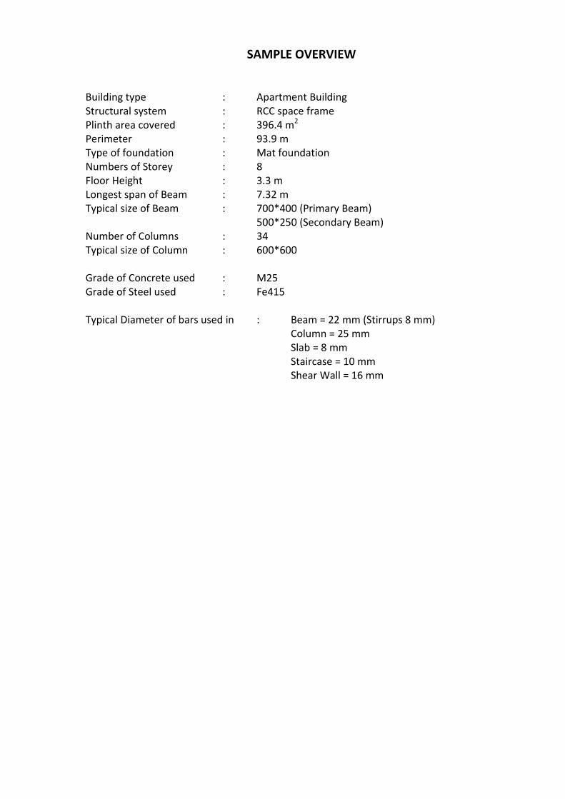
SAMPLE OVERVIEW
Building type : Apartment Building
Structural system : RCC space frame
Plinth area covered : 396.4 m2
Perimeter : 93.9 m
Type of foundation : Mat foundation
Numbers of Storey : 8
Floor Height : 3.3 m
Longest span of Beam : 7.32 m
Typical size of Beam : 700*400 (Primary Beam)
500*250 (Secondary Beam)
Number of Columns : 34
Typical size of Column : 600*600
Grade of Concrete used : M25
Grade of Steel used : Fe415
Typical Diameter of bars used in : Beam = 22 mm (Stirrups 8 mm)
Column = 25 mm
Slab = 8 mm
Staircase = 10 mm
Shear Wall = 16 mm
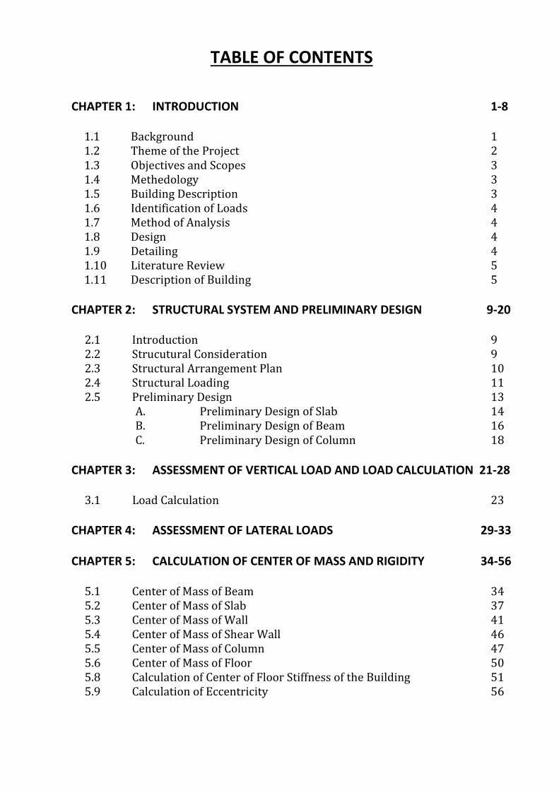
TABLE OF CONTENTS
CHAPTER 1: INTRODUCTION 1-8
1.1 Background 1
1.2 Theme of the Project 2
1.3 Objectives and Scopes 3
1.4 Methedology 3
1.5 Building Description 3
1.6 Identification of Loads 4
1.7 Method of Analysis 4
1.8 Design 4
1.9 Detailing 4
1.10 Literature Review 5
1.11 Description of Building 5
CHAPTER 2: STRUCTURAL SYSTEM AND PRELIMINARY DESIGN 9-20
2.1 Introduction 9
2.2 Strucutural Consideration 9
2.3 Structural Arrangement Plan 10
2.4 Structural Loading 11
2.5 Preliminary Design 13
A. Preliminary Design of Slab 14
B. Preliminary Design of Beam 16
C. Preliminary Design of Column 18
CHAPTER 3: ASSESSMENT OF VERTICAL LOAD AND LOAD CALCULATION 21-28
3.1 Load Calculation 23
CHAPTER 4: ASSESSMENT OF LATERAL LOADS 29-33
CHAPTER 5: CALCULATION OF CENTER OF MASS AND RIGIDITY 34-56
5.1 Center of Mass of Beam 34
5.2 Center of Mass of Slab 37
5.3 Center of Mass of Wall 41
5.4 Center of Mass of Shear Wall 46
5.5 Center of Mass of Column 47
5.6 Center of Mass of Floor 50
5.8 Calculation of Center of Floor Stiffness of the Building 51
5.9 Calculation of Eccentricity 56
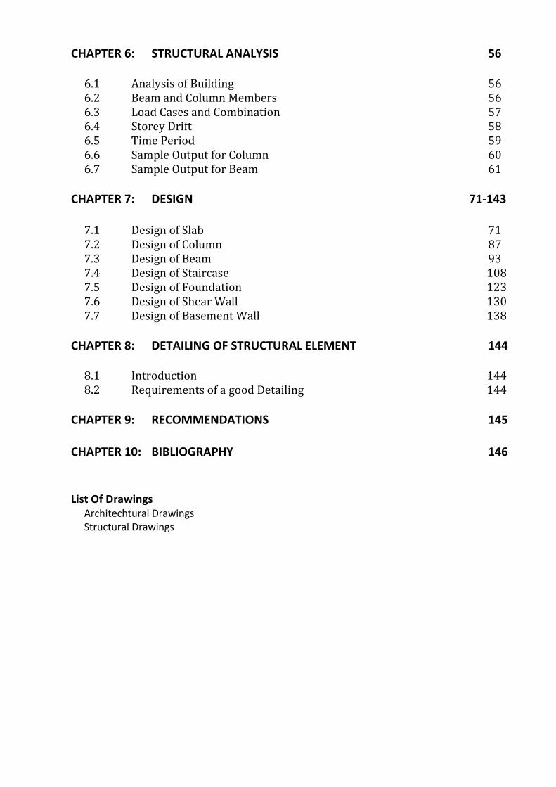
CHAPTER 6: STRUCTURAL ANALYSIS 56
6.1 Analysis of Building 56
6.2 Beam and Column Members 56
6.3 Load Cases and Combination 57
6.4 Storey Drift 58
6.5 Time Period 59
6.6 Sample Output for Column 60
6.7 Sample Output for Beam 61
CHAPTER 7: DESIGN 71-143
7.1 Design of Slab 71
7.2 Design of Column 87
7.3 Design of Beam 93
7.4 Design of Staircase 108
7.5 Design of Foundation 123
7.6 Design of Shear Wall 130
7.7 Design of Basement Wall 138
CHAPTER 8: DETAILING OF STRUCTURAL ELEMENT 144
8.1 Introduction 144
8.2 Requirements of a good Detailing 144
CHAPTER 9: RECOMMENDATIONS 145
CHAPTER 10: BIBLIOGRAPHY 146
List Of Drawings
Architechtural Drawings
Structural Drawings

ARCHITECTURAL DRAWINGS

STRUCTURAL DRAWINGS

EARTHQUAKE RESISTANT APARTMENT BUILDING INTRODUCTION
1
INTRODUCTION
1.1 BACKGROUND
A brief study of human history is sufficient to tell us that we, human beings, have
tried to protect ourselves from the adverse effect of wind, rain, temperature from the
beginning of our evolution. First we sought shelter in caves, but as we evolved and started to
understand the world we were living in we started to use the materials around us and started
to build our own shelter. Even today, in the 21st century, we still do the same; the only
difference is that in today’s world we seek other facilities, in addition to shelter, such as
comfort, sanitation, water supply and above all, safety.
Rapid increase in population of Kathmandu valley has made it difficult for people to
find a suitable place to build their homes and this problem will become more severe in the
future. In the recent trend as the land has become scarce, we have started to build upwards
into the sky. Consequently, larger and taller apartment buildings have become famous in
Kathmandu valley today. But as we build taller buildings in an earthquake prone region like
Kathmandu valley, we need to be cautious and follow the practice of fully, carefully
analyzing, designing and detailing the building before actually constructing it. This will make
the buildings safer which can eventually lead to avoidance of loss of lives and property in
case of a severe earthquake, which is imminent for our country.
Basically, a designer has to deal with various structures ranging from simple ones like
curtain rods and electric poles to more complex ones like multi storied frame buildings, shell
roof, bridges, etc. These structures are subjected to various loads like concentrated loads,
uniformly distributed loads, uniformly varying loads, live loads, earthquake loads, and
dynamic forces. The structure transfers the loads acting on it to the supports and ultimately to
the ground. While transferring the loads acting on the structure, the members of the structure
are subjected to internal forces like axial force, shear force, bending and torsion moments.
Structural analysis deals with the analyzing internal forces in the members of the structures.
Structural design deals with sizing various members of the structure to resist the
internal forces to which they are subjected during their effective life span. Unless, the proper
structural detailing method is adopted, the structural design will be no more effective. The
EARTHQUAKE RESISTANT APARTMENT BUILDING INTRODUCTION
2
Indian Standard code for practice should be adopted thoroughly for proper analysis design
and detailing with respect to safety, economy, stability and strength.
The project selected by our group is a multi storied apartment Building located in
Kathmandu. According to IS 1893:2002, Kathmandu lies in Zone V, the severest one. Hence,
the effect of earth quake is predominant than wind load. Thus, the building will be analyzed
for earthquake as lateral load. The seismic coefficient design method as stipulated in IS
1893:2002 will be applied to analyze the building for earthquake. Special reinforced concrete
moment resisting frame is considered as the main structural system of the building.
The final project report will be in complete conformity with the various stipulation in
Indian Standards, Code of Practice for Plane and Reinforced Concrete IS 456-2000, design
aids for reinforced concrete to IS456-2000(SP-16), criteria earthquake resistant design
structure IS 1893:2002, ductile detailing of reinforced concrete structures subjected to
seismic forces – code of practice IS 13920:1993, hand book on concrete reinforcement and
detailing SP-34. Use of these codes emphasizes on providing sufficient safety, economy,
strength and ductility besides satisfactory serviceability requirement of cracking and
deflection in concrete structures. These codes are based on principles of Limit State of
Design.
This project work has been undertaken as a partial requirement for B.E. degree in
Civil Engineering. This project work contains structural analysis, design and detailing of
multi-storey apartment building located in Kathmandu district. All the theoretical knowledge
of analysis and design acquired on the course work will be utilized with the practical
application. The main objective of the project is to acquaint in the practical aspects of Civil
Engineering.
1.2 THEME OF PROJECT WORK
This group, under the project, has undertaken the structural analysis and design of
multi-storey apartment building. The main aim of this project work under the title is to
acquire the knowledge and skill to emphasize the practical application. Besides, the
utilization of analytical methods and design approaches, exposure and application of various
available codes of practices are other aims of the project work.
EARTHQUAKE RESISTANT APARTMENT BUILDING INTRODUCTION
3
1.3 OBJECTIVES AND SCOPES
The specific objectives of the project work are:
1. Identification of structural arrangement of the plan.
2. Modeling of the building for the structural analysis.
3. Detail structural analysis using SAP.
4. Structural design of structural components.
5. Structural detailing of members and the system
1.4 METHEDOLOGY
To achieve the above objectives, the following scopes or works are planned:
1. Identification of building and requirement of space.
2. Determination of structural system of building to undertake the vertical and horizontal
loads.
3. Estimation of the loads including those due to earthquake.
4. Preliminary design for geometry of structural elements.
5. Calculation of the base shear and vertical distribution of equivalent earthquake load.
6. Identification of the load cases and the load combination cases.
7. Finite element modeling of the building and the input analysis.
8. Structural analysis of building by SAP 2000 Vs 15 for different cases of loads.
9. Review of the analysis outputs for design of individual components.
10. Design of RCC frame members, walls, mat foundation, staircase and other by limit
state method of design.
11. Detailing of individual member and the preparation of drawing as a part of working
construction documents.
1.5 BUILDING DESCRIPTION
Building type : Apartment Building
Structural system : RCC space frame
Plinth area covered : 396.4 m2
Perimeter : 93.9 m
Type of foundation : Mat foundation
Numbers of Storey : 8
Floor Height : 3.3m
EARTHQUAKE RESISTANT APARTMENT BUILDING INTRODUCTION
4
1.6 IDENTIFICATION OF LOADS
Dead loads are calculated as per IS 875 (part I):1987.
o R.C.C slab, beam, column = 25 KN/m3
o 18 mm thick Screed (1: 4) = 20.4 KN/m3
o 12.5 mm thick cement plaster (1:4) =20.4 KN/m3
o Brick wall (230 mm and 115 mm thick) = 19 KN/m3
Seismic load according to IS 1893 (Part I):2002, considering Kathmandu is located at
zone V.
Imposed load according to IS 875(Part II):1987 has been taken as
o Living room = 2 KN/m2
o Toilet = 2 KN/m2
o Corridor = 3 KN/m2
o Parking = 2.5 KN/m2
1.7 METHOD OF ANALYSIS
The building will be modeled in SAP2000 in second part of the project and the
analysis report will be used in the design of the various members.
1.8 DESIGN
The following materials will be assumed for the design of the elements:
Concrete Grade: M25 for all structural elements
Reinforcement Steel: Fe415 TMT for all structural element and Fe415 for stirrups
Limit State Method will be used for the design of RC elements. The design is based
on IS 456:2000, SP-16, IS 1893:2002, SP-34 and various other reinforced concrete books.
1.9 DETAILING
The space frame will be considered as a special moment resisting frame (SMRF) with
a special detailing to provide ductile behavior and comply with the requirements given in IS
13920:1993 and detailing (SP-34) and the books on Reinforced Concrete by various writers
are used.
EARTHQUAKE RESISTANT APARTMENT BUILDING INTRODUCTION
5
1.10 LITERATURE REVIEW
During the preparation of this report, we referred to the following books and reports:
Reinforced concrete - A.K. Jain.
Design of RCC Structural elements - S.S. Bhavikatti.
Limit State of Reinforced Concrete - P.C. Varghese.
Reinforced Concrete Design - S.K. Sinha
Previous project reports of multi-storey buildings.
1.11 DESCRIPTION OF BUILDING
A seven storey building for apartment has plan dimension as shown in architectural
drawing. It is located in seismic zone V on a site, which is of medium soil. Design of the
building for seismic load is done as per IS 1893 (part I) 2002.
A. General:
The example building consists of a main block and the structural design of the block
has to be done.
The building will be used for apartment. The external walls are of 230mm thick with
12.5mm plaster on both sides are considered.
The main beam rests centrally on columns to avoid local eccentricity.
For all structural elements, M25 grade concrete will be used.
Sizes of column are different, but a column has same size in different floor.
The floor diaphragms are assumed to be rigid.
Central line dimension are followed for analysis and design. In practice, it is advisable
to consider finite size joints width.
Seismic loads will be considered acting on the horizontal direction and not along the
vertical direction as it is not considered to be significant.
All dimensions are in mm, unless specified otherwise.
B. Geometry of building:
The general layout of the building is as shown in the architectural drawing. At ground
level no floor beams and slab is provided. Since the floor is directly rests on the ground (earth
filling and 1:4:8 at plinth level)
EARTHQUAKE RESISTANT APARTMENT BUILDING INTRODUCTION
6
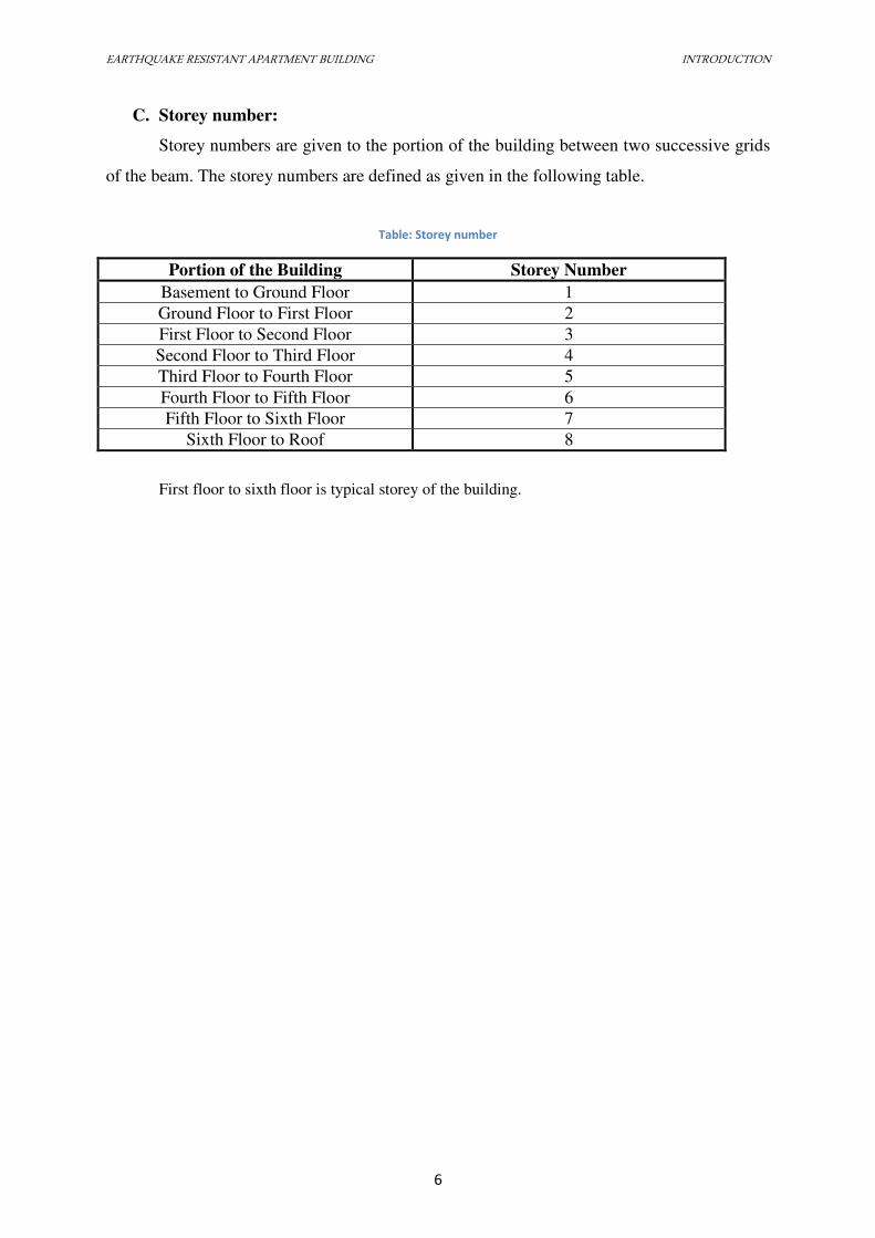
C. Storey number:
Storey numbers are given to the portion of the building between two successive grids
of the beam. The storey numbers are defined as given in the following table.
Table: Storey number
Portion of the Building Storey Number
Basement to Ground Floor 1
Ground Floor to First Floor 2
First Floor to Second Floor 3
Second Floor to Third Floor 4
Third Floor to Fourth Floor 5
Fourth Floor to Fifth Floor 6
Fifth Floor to Sixth Floor 7
Sixth Floor to Roof 8
First floor to sixth floor is typical storey of the building.
EARTHQUAKE RESISTANT APARTMENT BUILDING INTRODUCTION
7
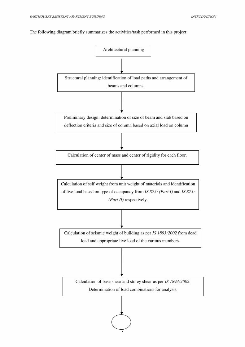
The following diagram briefly summarizes the activities/task performed in this project:
Architectural planning
Structural planning: identification of load paths and arrangement of
beams and columns.
Preliminary design: determination of size of beam and slab based on
deflection criteria and size of column based on axial load on column
Calculation of self weight from unit weight of materials and identification
of live load based on type of occupancy from IS 875: (Part I) and IS 875:
(Part II) respectively.
Calculation of seismic weight of building as per IS 1893:2002 from dead
load and appropriate live load of the various members.
Calculation of center of mass and center of rigidity for each floor.
Calculation of base shear and storey shear as per IS 1893:2002.
Determination of load combinations for analysis.
EARTHQUAKE RESISTANT APARTMENT BUILDING INTRODUCTION
8
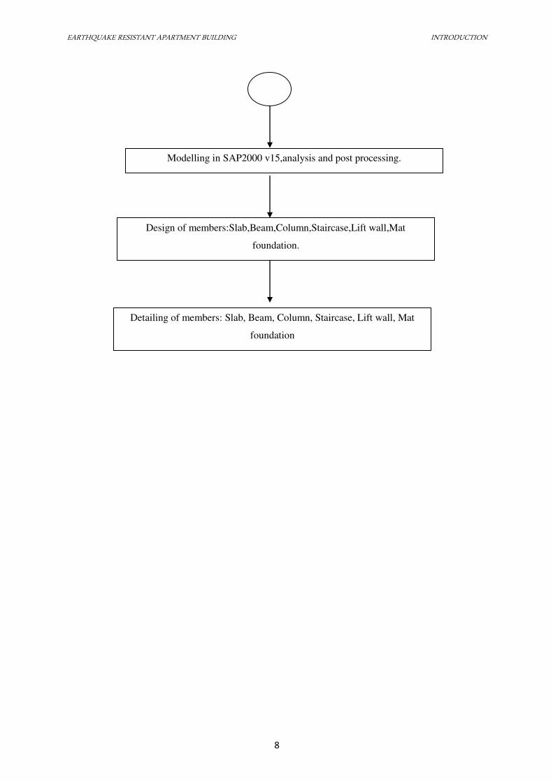
Modelling in SAP2000 v15,analysis and post processing.
Design of members:Slab,Beam,Column,Staircase,Lift wall,Mat
foundation.
Detailing of members: Slab, Beam, Column, Staircase, Lift wall, Mat
foundation
EARTHQUAKE RESISTANT APARTMENT BUILDING STRUCTURAL LOADING AND PRELIMINARY DESIGN
9
STRUCTURAL LOADING AND PRELIMINARY DESIGN
2.1 INTRODUCTION
This section of report deals mainly with following procedures:
1. Structural consideration
2. Structural arrangement plan
3. Preliminary sizing of members
4. Structural loading and assessment
5. Preliminary analysis of the structural members using appropriate method of analysis of
gravity and lateral loads
6. Verification of sizes/sections of members established based on the moments and forces
resulting from preliminary analysis.
2.2 STRUCTURAL CONSIDERATION
Structure should be designed such that it can withstand each and every force that is likely
to occur. It is of paramount importance that the structural form is sound. The architect achieves
the structural configuration and the structural engineer proportions the member sizes. There are
certain principles to be borne in mind. Stating briefly the structure should:
1. Be simple
2. Be symmetrical
3. Not to be too elongated in plan or elevation
4. Have uniform and continuous distribution of strength
5. Have its stiffness related to the subsoil properties
EARTHQUAKE RESISTANT APARTMENT BUILDING STRUCTURAL LOADING AND PRELIMINARY DESIGN
10
2.3 STRUCTURAL ARRANGEMENT PLAN
This involves determination of the form of the structure, the material for the same, the
structural system, the layout of its components, the method of analysis, and the philosophy of
structural design.
The principle elements of a R.C. building frame are as follows:
1. Slabs to cover the a large area
2. Beam should support the slabs and the walls
3. Columns to support beams and
4. Footing to distribute concentrated loads over a large area of supporting soil.
After getting an architectural plan of the building, the structural planning of the building
frame is done. This involves determination of the following:
1. Column position
2. Beam location
3. Spanning of slab
4. Location of expansion joint for length greater than 45m
5. Layout and planning of stair
6. Selection of the type of footing
The analysis of the building was done by the estimation of dimensions of various
structural members such as slab, beam, column and staircase with the help of preliminary design.
The different types of loads such as vertical load (dead + live and finishes) and lateral load
(earthquake) were calculated.
Earthquake being pre-dominant, only its effects was taken for lateral loads. Also,
combinations of such loads were taken into consideration. With the help of SAP2000, element
stresses of beams and columns were calculated.
EARTHQUAKE RESISTANT APARTMENT BUILDING STRUCTURAL LOADING AND PRELIMINARY DESIGN
11
2.4 STRUCTURAL LOADING
The building frames are designed for dead loads, live loads and earthquake loads.
a. Dead load
Dead load is produced by self weight of slabs, beams, columns, walls, parapet walls,
staircases and so on.
Dead load from slab is transferred as trapezoidal and triangular loads on beams.
Dead load from slab is transferred as uniformly distributed load on beams.
Self weight of beam is considered as uniformly distributed load.
Self weight of column is considered as the point load acting on the joint.
b. Live load
The magnitude of live load depends upon the type of occupancy of the building. These
are to be chosen from code IS 875:1987(part II) for various occupancies. The live load
distribution varies with time. Hence, each member is designed for worst combination of dead
load and live loads. A reduction in live load is allowed for a beam if it carries load from an area
greater than 50m2. The reduction is 5% for each 50m
2 subjected to maximum reduction of 25%.
Similarly all the floors of a residential or an office building may not be loaded
simultaneously. Therefore, the code permits reduction in live loads in design of columns, walls
and foundations as specified below:
Table: Reduction of live load
Storey below the
top most level
Reduction, % of live
load
First 0
Second 10
Third 20
Fourth 30
Fifth and sixth 40
Over sixth 50
EARTHQUAKE RESISTANT APARTMENT BUILDING STRUCTURAL LOADING AND PRELIMINARY DESIGN
12
Since we are designing the multistoried apartment building, live load intensity is taken as
per IS 875:1987(part II).
c. Earthquake load
Earthquake or seismic load on a structure depends on the side of the structure, maximum
earthquake intensity or string ground motion and the local soil, the stiffness design and
construction pattern, and its orientation in relation to the incident seismic waves. Building
experiences the horizontal distortion when subjected to earthquake motion so building should be
designed with lateral force resisting system. For design purpose, the resultant effects are usually
represented by the horizontal and vertical seismic coefficient αh & αv. Alternatively, the dynamic
analysis of the building is required under the action of the specified ground motion or design
response spectra. Since the probable maximum earthquake occurrences are not so frequent,
buildings are designed for such earthquakes so as to ensure that they remain elastic and damage-
free. Instead, reliance is placed on kinetic energy dissipation in the structure through plastic
deformation of elements and joints. The design forces are reduced accordingly. Thus, the main
philosophy of seismic designs is to reduce collapse of structure rather than a damage free
structure.
Methods of analysis:
There are basically two methods to determine the earthquake force in the building.
1. Seismic Coefficient Method or Static Method
2. Response Spectrum Method or Modal Analysis Method or Spectral Acceleration or
Dynamic Method
3. Time History Analysis
1. Seismic coefficient method:
The seismic coefficient method is generally applicable to building up to 40m in height
and those are more or less symmetrical in plan and elevation.
A building may be modeled as a series of 2D plane frames in two orthogonal directions.
Each node will have three degree of freedom: two translations and one rotation. Alternatively, a
building modeled as a 3D space frame. Each node will have six degrees of freedom: three
EARTHQUAKE RESISTANT APARTMENT BUILDING STRUCTURAL LOADING AND PRELIMINARY DESIGN
13
translations and three rotations, the wind loads and earthquake loads are assumed not to act
simultaneously. A building is designed for the worst of the two loads. The fact that the design
forces for the wind are greater than the seismic design forces does not obviate the need for
seismic detailing.
2. Response Spectrum Analysis
This method is applicable for those structures where modes other than the fundamental
one affect significantly the response of the structure. In this method, the response of multi degree
of freedom (MDOF) system is expressed as the superposition of model response, each modal
response being determined from spectral analysis of single degree of freedom (SDOF) system,
which is then combined to compute the total response. Modal analysis leads to the response
history of the structure to a specified ground motion.
d. Other loads
Other loads such as earth pressure, surcharge pressure and uplift pressure if exists are
also calculated.
2.5 PRELIMINARY DESIGN
Preliminary sizes of the flexural members of the structural system i.e. slab and beams are
worked out as per the limit state of serviceability (deflection) consideration by conforming to
IS456:2000 Clause 23.2.1. Similarly, for the compression member, i.e. columns, the cross
sectional area of the column is worked out from the net vertical axial load on the column lying in
the ground floor assuming suitable percentage of steel. The net vertical axial load on each
column is worked out from the factored dead load and live load on the contributing area, which
is taken as half of the slab areas adjacent to the column under consideration. The load is
increased by 25% for the earthquake load to give the net vertical load.
EARTHQUAKE RESISTANT APARTMENT BUILDING STRUCTURAL LOADING AND PRELIMINARY DESIGN
14
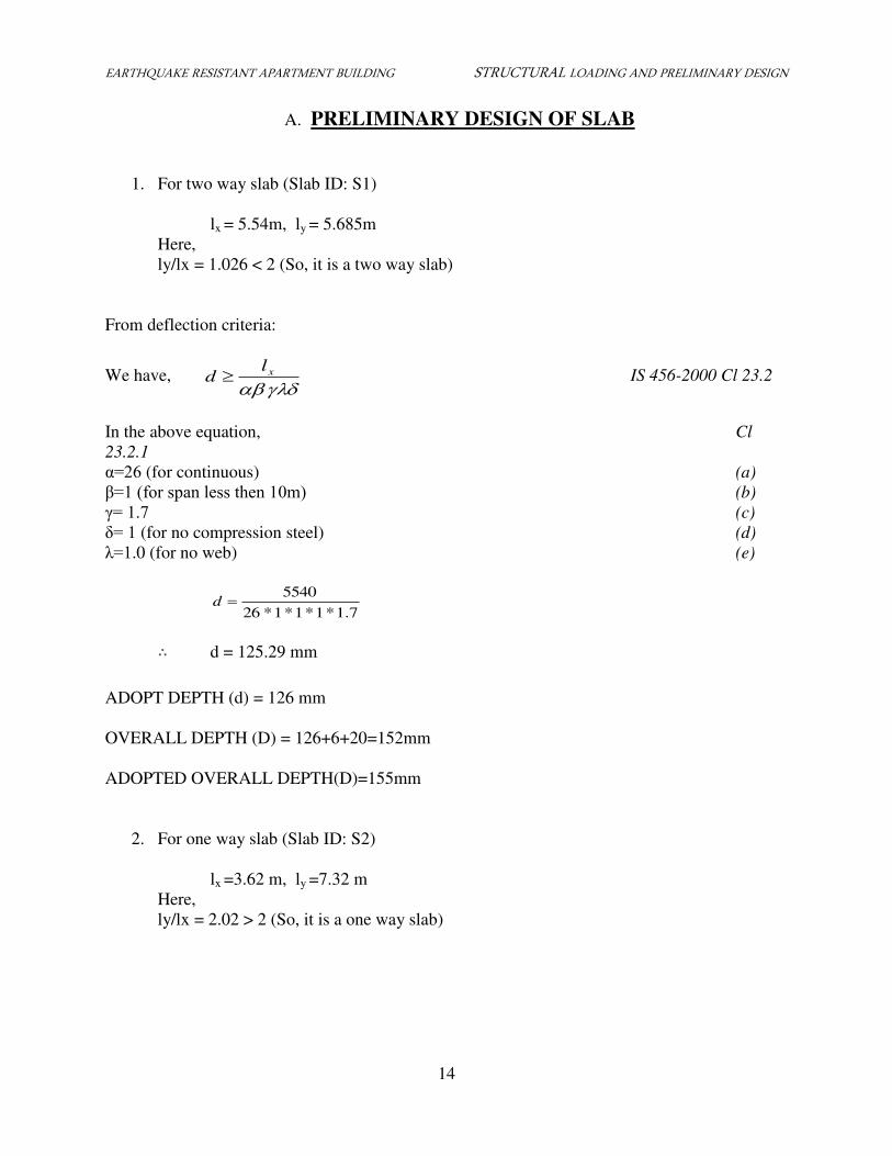
A. PRELIMINARY DESIGN OF SLAB
1. For two way slab (Slab ID: S1)
lx = 5.54m, ly = 5.685m
Here,
ly/lx = 1.026 < 2 (So, it is a two way slab)
From deflection criteria:
We have,
xld IS 456-2000 Cl 23.2
In the above equation, Cl
23.2.1
α=β6 (for continuous) (a)
=1 (for span less then 10m) (b)
= 1.7 (c)
δ= 1 (for no compression steel) (d)
λ=1.0 (for no web) (e)
7.1*1*1*1*26
5540d
∴ d = 125.29 mm
ADOPT DEPTH (d) = 126 mm
OVERALL DEPTH (D) = 126+6+20=152mm
ADOPTED OVERALL DEPTH(D)=155mm
2. For one way slab (Slab ID: S2)
lx =3.62 m, ly =7.32 m
Here,
ly/lx = 2.02 > 2 (So, it is a one way slab)
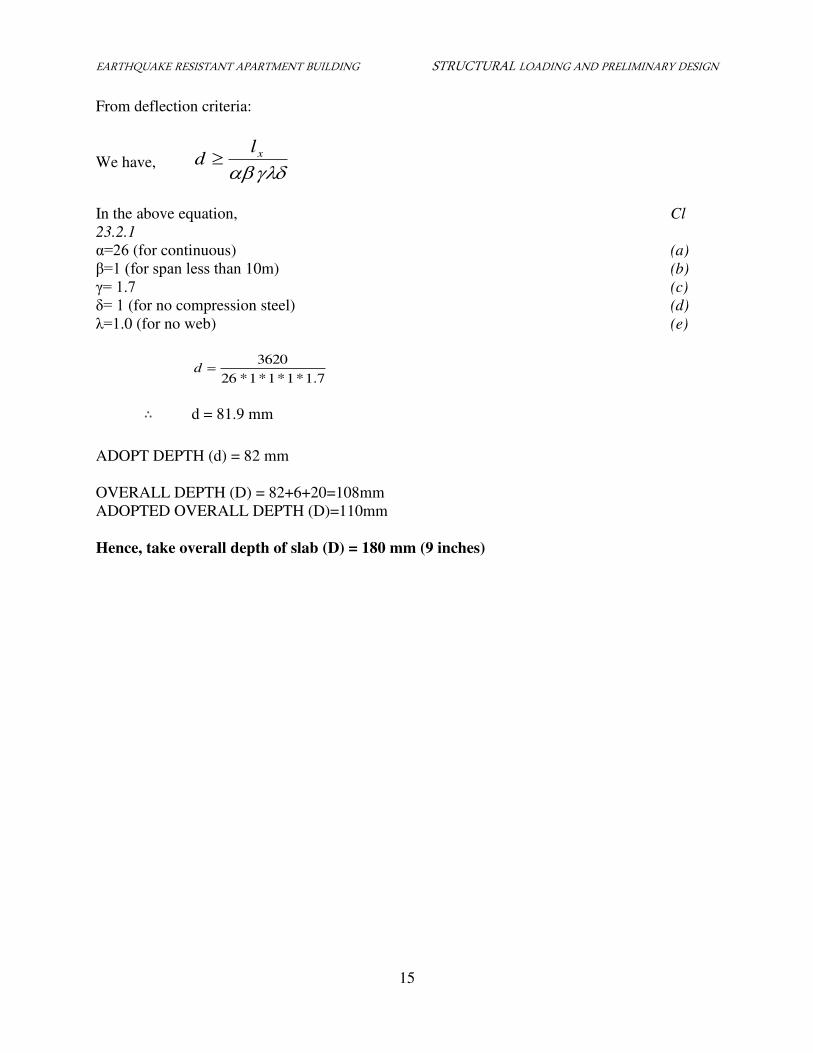
EARTHQUAKE RESISTANT APARTMENT BUILDING STRUCTURAL LOADING AND PRELIMINARY DESIGN
15
From deflection criteria:
We have, xld
In the above equation, Cl
23.2.1
α=β6 (for continuous) (a)
=1 (for span less than 10m) (b)
= 1.7 (c)
δ= 1 (for no compression steel) (d)
λ=1.0 (for no web) (e)
7.1*1*1*1*26
3620d
∴ d = 81.9 mm
ADOPT DEPTH (d) = 82 mm
OVERALL DEPTH (D) = 82+6+20=108mm
ADOPTED OVERALL DEPTH (D)=110mm
Hence, take overall depth of slab (D) = 180 mm (9 inches)
EARTHQUAKE RESISTANT APARTMENT BUILDING STRUCTURAL LOADING AND PRELIMINARY DESIGN
16
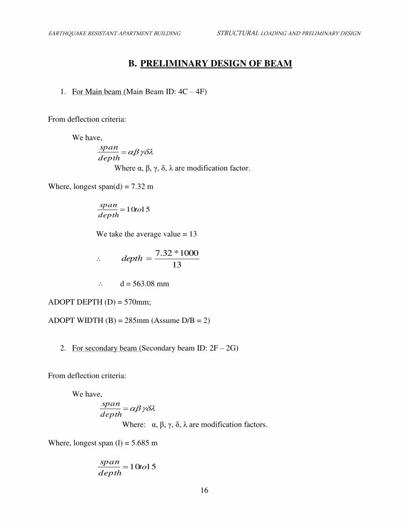
B. PRELIMINARY DESIGN OF BEAM
1. For Main beam (Main Beam ID: 4C – 4F)
From deflection criteria:
We have,
depth
span
Where α, , , δ, λ are modification factor.
Where, longest span(d) = 7.32 m
1510todepth
span
We take the average value = 13
∴ 13
1000*32.7depth
∴ d = 563.08 mm
ADOPT DEPTH (D) = 570mm;
ADOPT WIDTH (B) = 285mm (Assume D/B = 2)
2. For secondary beam (Secondary beam ID: 2F – 2G)
From deflection criteria:
We have,
depth
span
Where: α, , , δ, λ are modification factors.
Where, longest span (l) = 5.685 m
1510todepth
span
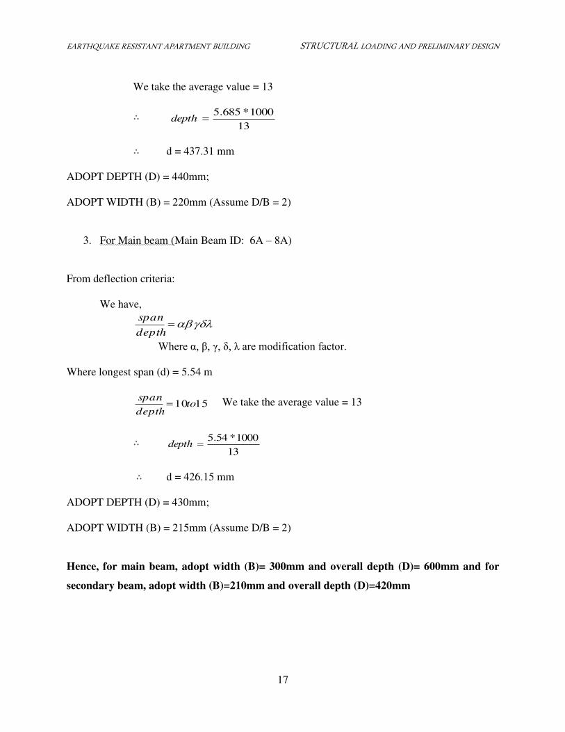
EARTHQUAKE RESISTANT APARTMENT BUILDING STRUCTURAL LOADING AND PRELIMINARY DESIGN
17
We take the average value = 13
∴ 13
1000*685.5depth
∴ d = 437.31 mm
ADOPT DEPTH (D) = 440mm;
ADOPT WIDTH (B) = 220mm (Assume D/B = 2)
3. For Main beam (Main Beam ID: 6A – 8A)
From deflection criteria:
We have,
depth
span
Where α, , , δ, λ are modification factor.
Where longest span (d) = 5.54 m
1510todepth
span We take the average value = 13
∴ 13
1000*54.5depth
∴ d = 426.15 mm
ADOPT DEPTH (D) = 430mm;
ADOPT WIDTH (B) = 215mm (Assume D/B = 2)
Hence, for main beam, adopt width (B)= 300mm and overall depth (D)= 600mm and for
secondary beam, adopt width (B)=210mm and overall depth (D)=420mm
EARTHQUAKE RESISTANT APARTMENT BUILDING STRUCTURAL LOADING AND PRELIMINARY DESIGN
18
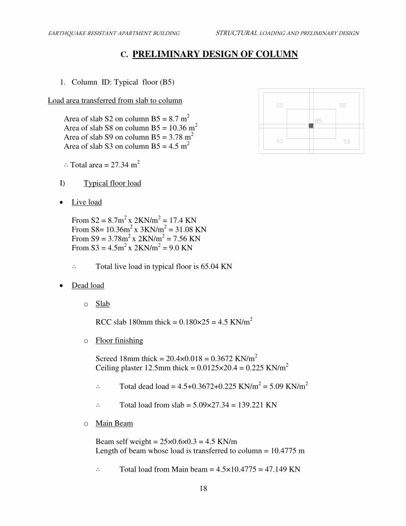
C. PRELIMINARY DESIGN OF COLUMN
1. Column ID: Typical floor (B5)
Load area transferred from slab to column
Area of slab S2 on column B5 = 8.7 m2
Area of slab S8 on column B5 = 10.36 m2
Area of slab S9 on column B5 = 3.78 m2
Area of slab S3 on column B5 = 4.5 m2
∴ Total area = 27.34 m2
I) Typical floor load
Live load
From S2 = 8.7m2
x 2KN/m2 = 17.4 KN
From S8= 10.36m2
x 3KN/m2 = 31.08 KN
From S9 = 3.78m2
x 2KN/m2 = 7.56 KN
From S3 = 4.5m2
x 2KN/m2 = 9.0 KN
∴ Total live load in typical floor is 65.04 KN
Dead load
o Slab
RCC slab 180mm thick = 0.180×25 = 4.5 KN/m2
o Floor finishing
Screed 18mm thick = 20.4×0.018 = 0.3672 KN/m2
Ceiling plaster 12.5mm thick = 0.0125×20.4 = 0.225 KN/m2
∴ Total dead load = 4.5+0.3672+0.225 KN/m2 = 5.09 KN/m
2
∴ Total load from slab = 5.09×27.34 = 139.221 KN
o Main Beam
Beam self weight = 25×0.6×0.3 = 4.5 KN/m
Length of beam whose load is transferred to column = 10.4775 m
∴ Total load from Main beam = 4.5×10.4775 = 47.149 KN
EARTHQUAKE RESISTANT APARTMENT BUILDING STRUCTURAL LOADING AND PRELIMINARY DESIGN
19
o Secondary Beam
Beam self weight = 25×0.42×0.21 = 2.205 KN/m
Length of beam whose load is transferred to column = 5.105 m
∴ Total load from Main beam = 2.205×5.105 = 11.257 KN
o Wall
Self weight of brick and mortar = b×thickness×height.
= 19×0.23×3.3 = 14.421 KN/m
Self weight of plaster 12.5 mm = 2× c×thickness×height.
= 2×20.4×0.0125×3.3= 1.53 KN/m
Total load intensity after deducting 30% for opening
= 0.7× (14.421+1.53) = 11.166 KN/m
Total load from wall= 11.166 ×6.18 = 69.004 KN
∴ Total load on column from typical floor = LLDL
= 139.221+47.149+11.257+69.004+65.04
= 331.671 KN
II) Ground floor load
Dead load = 139.221+47.149+11.257 (DL of slab+ Plaster + FF + DL of beam)
= 197.627 KN
Live load intensity = 2.5 KN/m2
Live load = 2.5×27.34 = 68.35 KN
∴ Total load on column from ground floor = 197.627+68.35= 265.977 KN
III) Roof load
Load from roof = DL+LL
=197.627+1.5×27.34 (assuming access provided)
=238.697 KN
∴ Total load in column= 265.977+238.697+6×331.671 = 2494.7 KN
Factored total load = 1.5×2494.7 KN = 3742.05 KN
EARTHQUAKE RESISTANT APARTMENT BUILDING STRUCTURAL LOADING AND PRELIMINARY DESIGN
20
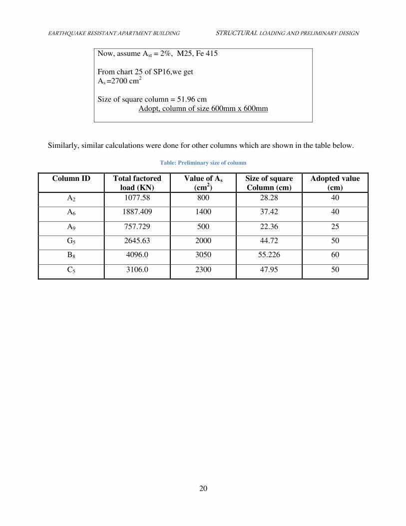
Now, assume Ast = 2%, M25, Fe 415
From chart 25 of SP16,we get
As =2700 cm2
Size of square column = 51.96 cm
Adopt, column of size 600mm x 600mm
Similarly, similar calculations were done for other columns which are shown in the table below.
Table: Preliminary size of column
Column ID Total factored
load (KN)
Value of As
(cm2)
Size of square
Column (cm)
Adopted value
(cm)
A2 1077.58 800 28.28 40
A6 1887.409 1400 37.42 40
A9 757.729 500 22.36 25
G5 2645.63 2000 44.72 50
B8 4096.0 3050 55.226 60
C5 3106.0 2300 47.95 50
EARTHQUAKE RESISTANT APARTMENT BUILDING ASSESSMENT OF VERTICAL LOAD AND LOAD CALCULATION
21
ASSESSMENT OF VERTICAL LOAD AND LOAD
CALCULATION
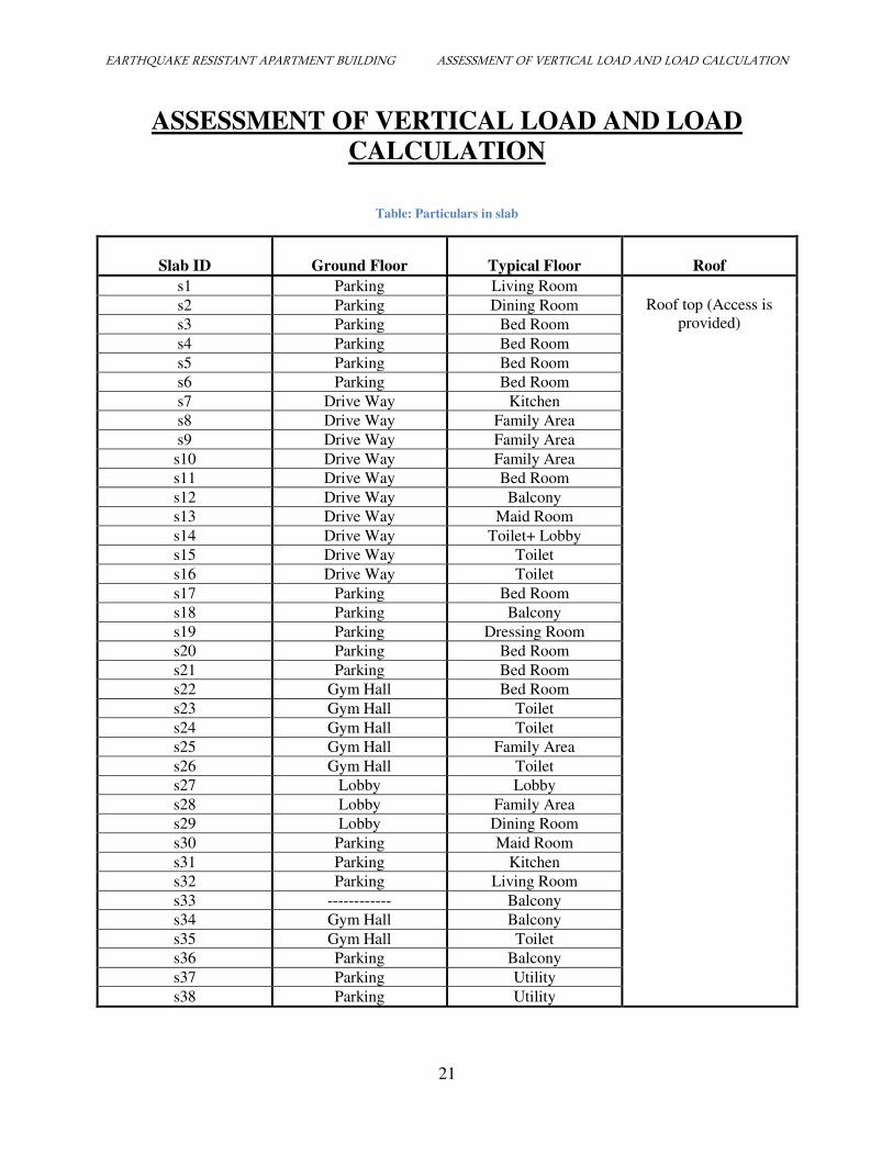
Table: Particulars in slab
Slab ID
Ground Floor
Typical Floor
Roof
s1 Parking Living Room
Roof top (Access is
provided) s2 Parking Dining Room
s3 Parking Bed Room
s4 Parking Bed Room
s5 Parking Bed Room
s6 Parking Bed Room
s7 Drive Way Kitchen
s8 Drive Way Family Area
s9 Drive Way Family Area
s10 Drive Way Family Area
s11 Drive Way Bed Room
s12 Drive Way Balcony
s13 Drive Way Maid Room
s14 Drive Way Toilet+ Lobby
s15 Drive Way Toilet
s16 Drive Way Toilet
s17 Parking Bed Room
s18 Parking Balcony
s19 Parking Dressing Room
s20 Parking Bed Room
s21 Parking Bed Room
s22 Gym Hall Bed Room
s23 Gym Hall Toilet
s24 Gym Hall Toilet
s25 Gym Hall Family Area
s26 Gym Hall Toilet
s27 Lobby Lobby
s28 Lobby Family Area
s29 Lobby Dining Room
s30 Parking Maid Room
s31 Parking Kitchen
s32 Parking Living Room
s33 ------------ Balcony
s34 Gym Hall Balcony
s35 Gym Hall Toilet
s36 Parking Balcony
s37 Parking Utility
s38 Parking Utility
EARTHQUAKE RESISTANT APARTMENT BUILDING ASSESSMENT OF VERTICAL LOAD AND LOAD CALCULATION
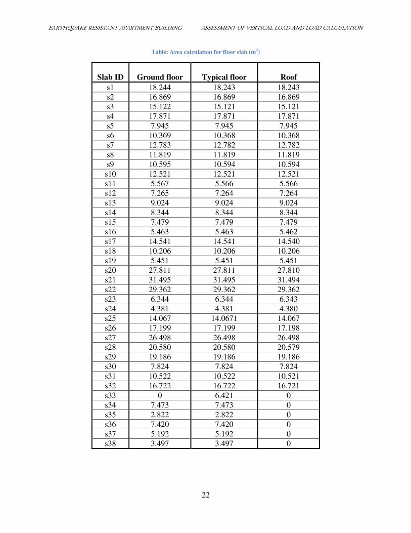
22
Table: Area calculation for floor slab (m2)
Slab ID
Ground floor
Typical floor
Roof
s1 18.244 18.243 18.243
s2 16.869 16.869 16.869
s3 15.122 15.121 15.121
s4 17.871 17.871 17.871
s5 7.945 7.945 7.945
s6 10.369 10.368 10.368
s7 12.783 12.782 12.782
s8 11.819 11.819 11.819
s9 10.595 10.594 10.594
s10 12.521 12.521 12.521
s11 5.567 5.566 5.566
s12 7.265 7.264 7.264
s13 9.024 9.024 9.024
s14 8.344 8.344 8.344
s15 7.479 7.479 7.479
s16 5.463 5.463 5.462
s17 14.541 14.541 14.540
s18 10.206 10.206 10.206
s19 5.451 5.451 5.451
s20 27.811 27.811 27.810
s21 31.495 31.495 31.494
s22 29.362 29.362 29.362
s23 6.344 6.344 6.343
s24 4.381 4.381 4.380
s25 14.067 14.0671 14.067
s26 17.199 17.199 17.198
s27 26.498 26.498 26.498
s28 20.580 20.580 20.579
s29 19.186 19.186 19.186
s30 7.824 7.824 7.824
s31 10.522 10.522 10.521
s32 16.722 16.722 16.721
s33 0 6.421 0
s34 7.473 7.473 0
s35 2.822 2.822 0
s36 7.420 7.420 0
s37 5.192 5.192 0
s38 3.497 3.497 0
EARTHQUAKE RESISTANT APARTMENT BUILDING ASSESSMENT OF VERTICAL LOAD AND LOAD CALCULATION
23
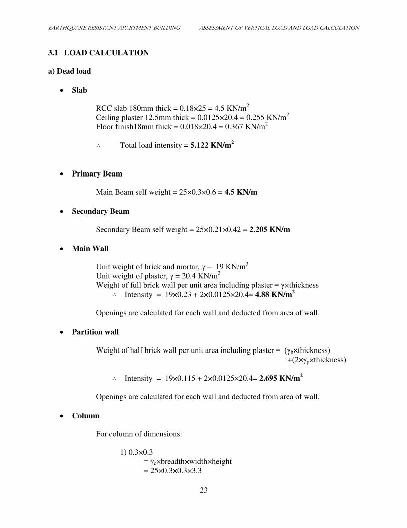
3.1 LOAD CALCULATION
a) Dead load
Slab
RCC slab 180mm thick = 0.18×25 = 4.5 KN/m2
Ceiling plaster 12.5mm thick = 0.0125×20.4 = 0.255 KN/m2
Floor finish18mm thick = 0.018×20.4 = 0.367 KN/m2
∴ Total load intensity = 5.122 KN/m2
Primary Beam
Main Beam self weight = 25×0.3×0.6 = 4.5 KN/m
Secondary Beam
Secondary Beam self weight = 25×0.21×0.42 = 2.205 KN/m
Main Wall
Unit weight of brick and mortar, γ = 19 KN/m3
Unit weight of plaster, γ = 20.4 KN/m3
Weight of full brick wall per unit area including plaster = γ×thickness
∴ Intensity = 19×0.23 + 2×0.0125×20.4= 4.88 KN/m2
Openings are calculated for each wall and deducted from area of wall.
Partition wall
Weight of half brick wall per unit area including plaster = (γb×thickness)
+(2×γp×thickness)
∴ Intensity = 19×0.115 + 2×0.0125×20.4= 2.695 KN/m2
Openings are calculated for each wall and deducted from area of wall.
Column
For column of dimensions:
1) 0.3×0.3
= γc×breadth×width×height
= 25×0.3×0.3×3.3
EARTHQUAKE RESISTANT APARTMENT BUILDING ASSESSMENT OF VERTICAL LOAD AND LOAD CALCULATION
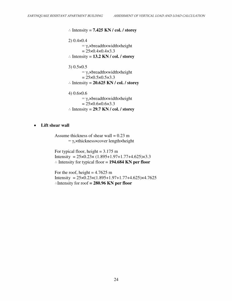
24
∴ Intensity = 7.425 KN / col. / storey
2) 0.4×0.4
= γc×breadth×width×height
= 25×0.4×0.4×3.3
∴ Intensity = 13.2 KN / col. / storey
3) 0.5×0.5
= γc×breadth×width×height
= 25×0.5×0.5×3.3 ∴ Intensity = 20.625 KN / col. / storey
4) 0.6×0.6
= γc×breadth×width×height
= 25×0.6×0.6×3.3 ∴ Intensity = 29.7 KN / col. / storey
Lift shear wall
Assume thickness of shear wall = 0.23 m
= γc×thickness×cover length×height
For typical floor, height = 3.175 m
Intensity = 25×0.23× (1.895+1.97+1.77+4.625)×3.3 ∴ Intensity for typical floor = 194.684 KN per floor
For the roof, height = 4.7625 m
Intensity = 25×0.23×(1.895+1.97+1.77+4.625)×4.7625 ∴Intensity for roof = 280.96 KN per floor
EARTHQUAKE RESISTANT APARTMENT BUILDING ASSESSMENT OF VERTICAL LOAD AND LOAD CALCULATION
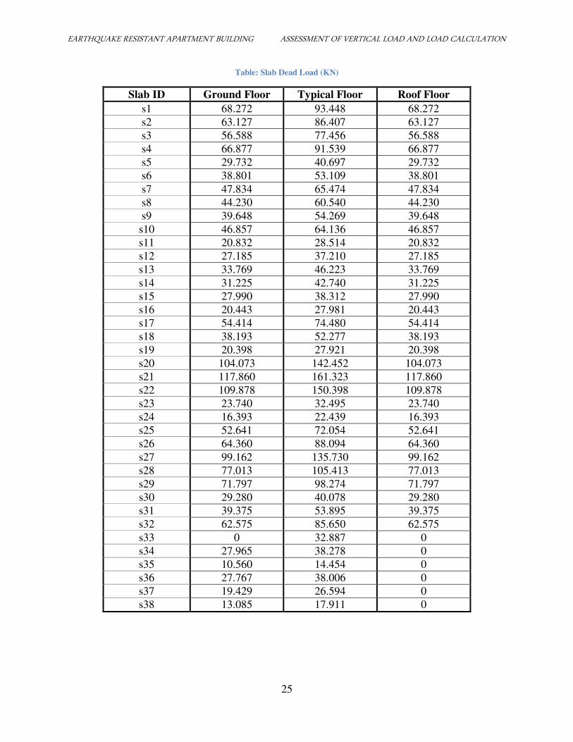
25
Table: Slab Dead Load (KN)
Slab ID Ground Floor Typical Floor Roof Floor
s1 68.272 93.448 68.272
s2 63.127 86.407 63.127
s3 56.588 77.456 56.588
s4 66.877 91.539 66.877
s5 29.732 40.697 29.732
s6 38.801 53.109 38.801
s7 47.834 65.474 47.834
s8 44.230 60.540 44.230
s9 39.648 54.269 39.648
s10 46.857 64.136 46.857
s11 20.832 28.514 20.832
s12 27.185 37.210 27.185
s13 33.769 46.223 33.769
s14 31.225 42.740 31.225
s15 27.990 38.312 27.990
s16 20.443 27.981 20.443
s17 54.414 74.480 54.414
s18 38.193 52.277 38.193
s19 20.398 27.921 20.398
s20 104.073 142.452 104.073
s21 117.860 161.323 117.860
s22 109.878 150.398 109.878
s23 23.740 32.495 23.740
s24 16.393 22.439 16.393
s25 52.641 72.054 52.641
s26 64.360 88.094 64.360
s27 99.162 135.730 99.162
s28 77.013 105.413 77.013
s29 71.797 98.274 71.797
s30 29.280 40.078 29.280
s31 39.375 53.895 39.375
s32 62.575 85.650 62.575
s33 0 32.887 0
s34 27.965 38.278 0
s35 10.560 14.454 0
s36 27.767 38.006 0
s37 19.429 26.594 0
s38 13.085 17.911 0
EARTHQUAKE RESISTANT APARTMENT BUILDING ASSESSMENT OF VERTICAL LOAD AND LOAD CALCULATION
26
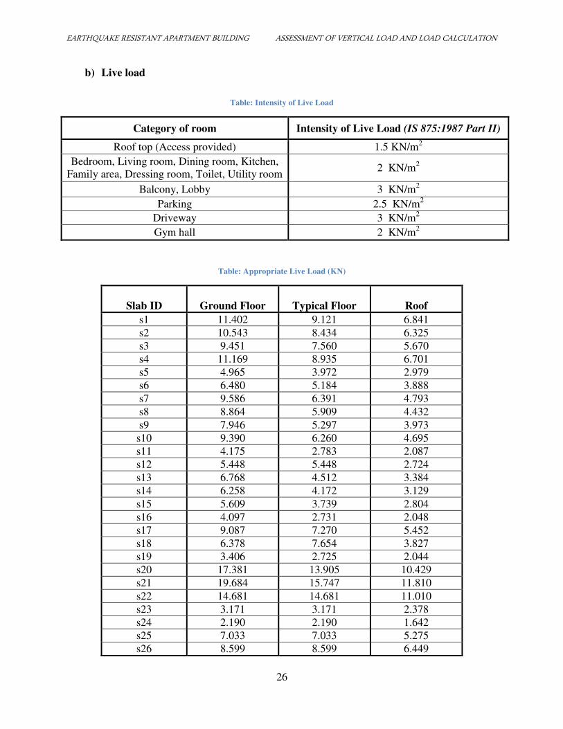
b) Live load
Table: Intensity of Live Load
Category of room Intensity of Live Load (IS 875:1987 Part II)
Roof top (Access provided) 1.5 KN/m2
Bedroom, Living room, Dining room, Kitchen,
Family area, Dressing room, Toilet, Utility room 2 KN/m
2
Balcony, Lobby 3 KN/m2
Parking 2.5 KN/m2
Driveway 3 KN/m2
Gym hall 2 KN/m2
Table: Appropriate Live Load (KN)
Slab ID
Ground Floor
Typical Floor
Roof
s1 11.402 9.121 6.841
s2 10.543 8.434 6.325
s3 9.451 7.560 5.670
s4 11.169 8.935 6.701
s5 4.965 3.972 2.979
s6 6.480 5.184 3.888
s7 9.586 6.391 4.793
s8 8.864 5.909 4.432
s9 7.946 5.297 3.973
s10 9.390 6.260 4.695
s11 4.175 2.783 2.087
s12 5.448 5.448 2.724
s13 6.768 4.512 3.384
s14 6.258 4.172 3.129
s15 5.609 3.739 2.804
s16 4.097 2.731 2.048
s17 9.087 7.270 5.452
s18 6.378 7.654 3.827
s19 3.406 2.725 2.044
s20 17.381 13.905 10.429
s21 19.684 15.747 11.810
s22 14.681 14.681 11.010
s23 3.171 3.171 2.378
s24 2.190 2.190 1.642
s25 7.033 7.033 5.275
s26 8.599 8.599 6.449
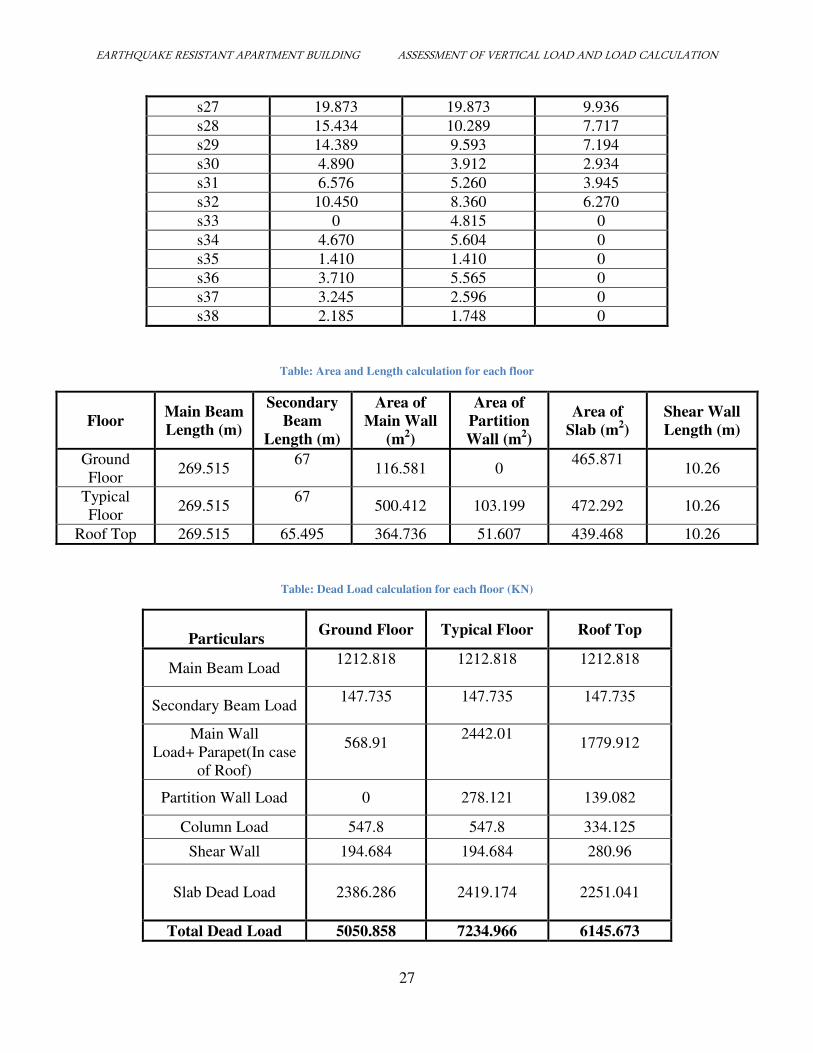
EARTHQUAKE RESISTANT APARTMENT BUILDING ASSESSMENT OF VERTICAL LOAD AND LOAD CALCULATION
27
s27 19.873 19.873 9.936
s28 15.434 10.289 7.717
s29 14.389 9.593 7.194
s30 4.890 3.912 2.934
s31 6.576 5.260 3.945
s32 10.450 8.360 6.270
s33 0 4.815 0
s34 4.670 5.604 0
s35 1.410 1.410 0
s36 3.710 5.565 0
s37 3.245 2.596 0
s38 2.185 1.748 0
Table: Area and Length calculation for each floor
Floor Main Beam
Length (m)
Secondary
Beam
Length (m)
Area of
Main Wall
(m2)
Area of
Partition
Wall (m2)
Area of
Slab (m2)
Shear Wall
Length (m)
Ground
Floor 269.515
67 116.581 0
465.871
10.26
Typical
Floor 269.515
67 500.412 103.199 472.292 10.26
Roof Top 269.515 65.495 364.736 51.607 439.468 10.26
Table: Dead Load calculation for each floor (KN)
Particulars Ground Floor Typical Floor Roof Top
Main Beam Load 1212.818
1212.818
1212.818
Secondary Beam Load 147.735
147.735
147.735
Main Wall
Load+ Parapet(In case
of Roof)
568.91
2442.01
1779.912
Partition Wall Load 0 278.121 139.082
Column Load 547.8 547.8 334.125
Shear Wall 194.684 194.684 280.96
Slab Dead Load 2386.286
2419.174
2251.041
Total Dead Load 5050.858 7234.966 6145.673
EARTHQUAKE RESISTANT APARTMENT BUILDING ASSESSMENT OF VERTICAL LOAD AND LOAD CALCULATION
28
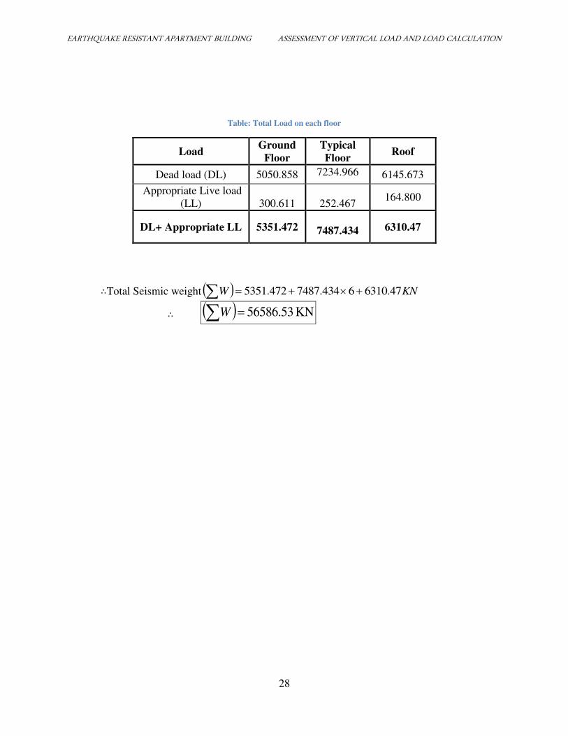
Table: Total Load on each floor
Load Ground
Floor
Typical
Floor Roof
Dead load (DL) 5050.858 7234.966 6145.673
Appropriate Live load
(LL) 300.611
252.467 164.800
DL+ Appropriate LL 5351.472
7487.434 6310.47
∴Total Seismic weight KNW 6310.4767487.4345351.472 ∴ KN 56586.53W
EARTHQUAKE RESISTANT APARTMENT BUILDING ASSESSMENT OF LATERAL LOADS
29
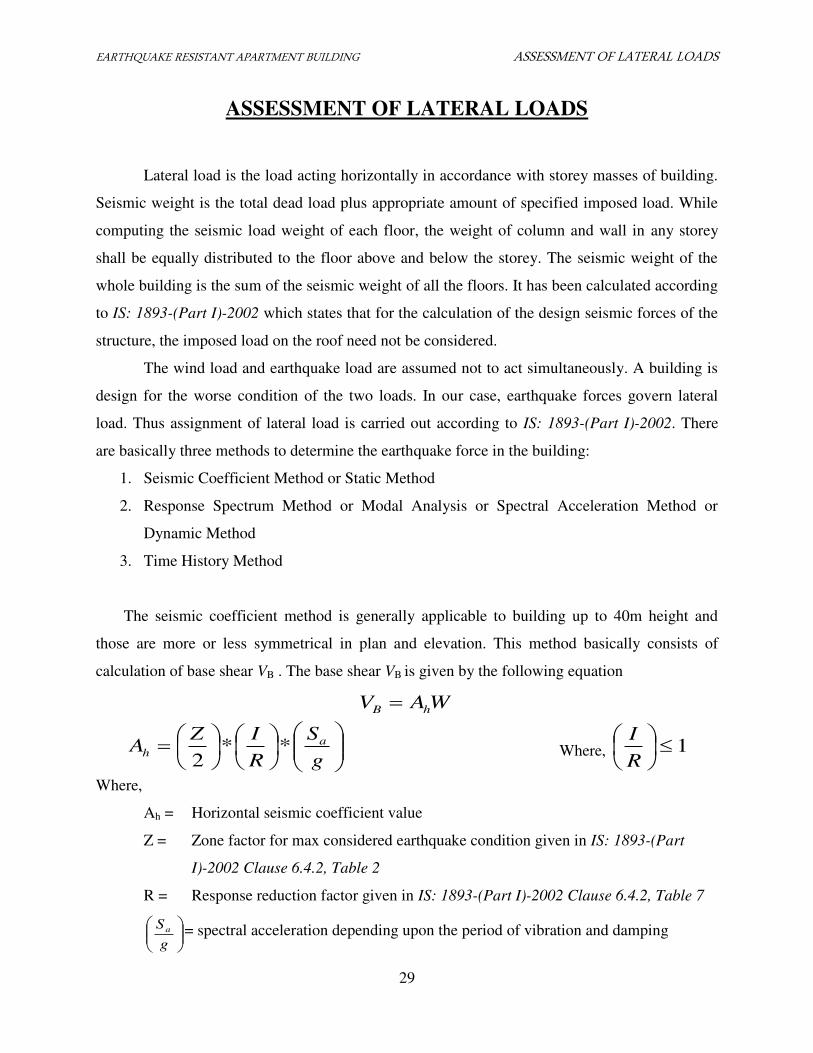
ASSESSMENT OF LATERAL LOADS
Lateral load is the load acting horizontally in accordance with storey masses of building.
Seismic weight is the total dead load plus appropriate amount of specified imposed load. While
computing the seismic load weight of each floor, the weight of column and wall in any storey
shall be equally distributed to the floor above and below the storey. The seismic weight of the
whole building is the sum of the seismic weight of all the floors. It has been calculated according
to IS: 1893-(Part I)-2002 which states that for the calculation of the design seismic forces of the
structure, the imposed load on the roof need not be considered.
The wind load and earthquake load are assumed not to act simultaneously. A building is
design for the worse condition of the two loads. In our case, earthquake forces govern lateral
load. Thus assignment of lateral load is carried out according to IS: 1893-(Part I)-2002. There
are basically three methods to determine the earthquake force in the building:
1. Seismic Coefficient Method or Static Method
2. Response Spectrum Method or Modal Analysis or Spectral Acceleration Method or
Dynamic Method
3. Time History Method
The seismic coefficient method is generally applicable to building up to 40m height and
those are more or less symmetrical in plan and elevation. This method basically consists of
calculation of base shear VB . The base shear VB is given by the following equation
WAV hB
g
S
R
IZA a
h **2
Where, 1
R
I
Where,
Ah = Horizontal seismic coefficient value
Z = Zone factor for max considered earthquake condition given in IS: 1893-(Part
I)-2002 Clause 6.4.2, Table 2
R = Response reduction factor given in IS: 1893-(Part I)-2002 Clause 6.4.2, Table 7
g
Sa = spectral acceleration depending upon the period of vibration and damping
EARTHQUAKE RESISTANT APARTMENT BUILDING ASSESSMENT OF LATERAL LOADS
30
as given in IS: 1893-(part I)-2002. Clause 6.4.2, Figure 2
I = post – disaster importance factor depending on the life and function of structure,
historical value or economic importance as IS: 1893-(Part I)-2002, Table 6
W = Seismic weight which includes:
Floor wise dead load consisting of weight of floor, beams, parapet, fixed
permanent equipment and half the walls and column etc. above and below.
Reduce live load on the building (25% of live load for LL ≤ 3.0KN/m2 and
50% of LL > 3.0 KN/m2)
T = Estimates natural or fundamental period of vibration of the building in second
T = 0.075xH0.75
For moment resisting concrete building
T = 2/1
09.0sD
H For braced concrete building
H = Total height of building in m in a direction perpendicular to the applied
earthquake force.
Ds = Dimension of building in m in a direction parallel to the applied earthquake force.
After calculating the base shear VB, the distribution of earthquake force on different floor
is determined as follows:
Bn
i
ii
ii V
hW
hWQi *
1
2
2
Where,
Qi = horizontal force acting at any floor i
Wi = weight of ith
storey assumed to be lumped at ith
floor
Hi = height if ith
floor above base of frame
n = number of storey of the building
Once the floor loads are obtained, the frame can be analyzed by Portal or Cantilever
Method or Stiffness Matrix Method.
The design storey shear in any storey is distributed to the various element of the vertical
lateral force resisting system in proportion to their rigidity considering the rigidity of diaphragm.
EARTHQUAKE RESISTANT APARTMENT BUILDING ASSESSMENT OF LATERAL LOADS
31
For both X and Y direction,
Z (zonal factor)=0.36 (very severe) IS 1893 (part I): Clause 6.4.2: Table 2
I (Importance factor) = 1.5 IS 1893 (part I): Clause 6.4.2: Table 6
R (Response reduction factor) = 5 IS 1893 (part I): Clause 6.4.2: Table 7
d
hTa
09.0
where,
h=height of building
d=base dimension of building at plinth level (m), along the considered direction of lateral
force
Now, for X direction, d = 28.515 m
515.28
5.24*09.0aT
∴ 42.0aT
For medium soil sites (Cl-6.4.5) and for 0.10≤Ta≤0.55
5.2g
Sa
Similarly, for Y direction, d = 15.625 m
565.15
5.24*09.0aT
∴ 55.0aT
For medium soil sites (Cl-6.4.5) and 0.10≤Ta≤0.55
5.2g
Sa
Since all parameters (Z, I, R, g
Sa
) are equal for both X and Y direction, the Base Shear (VB) and
design Lateral force at floor (Qi) are also same for both direction.
EARTHQUAKE RESISTANT APARTMENT BUILDING ASSESSMENT OF LATERAL LOADS
32
Thus,
g
S
R
IZA a
h **2
Where, Ah = Design horizontal seismic coefficient Cl-6.4.2
or, 5.2*5
5.1*
2
36.0
hA
∴ 135.0hA
Also,
WAV hB
Where, VB = Base shear and W= Seismic weight
or, 56586.53135.0 BV ∴ KNVB 7639.182
We have,
Bn
i
ii
ii V
hW
hWQi *
1
2
2
Cl-7.7.1
Here, ∑wihi2 = 15790216.69 KNm
2
Thus,
7639.182915790216.6
3.35351.472 2
1
Q
KNQ 194.281
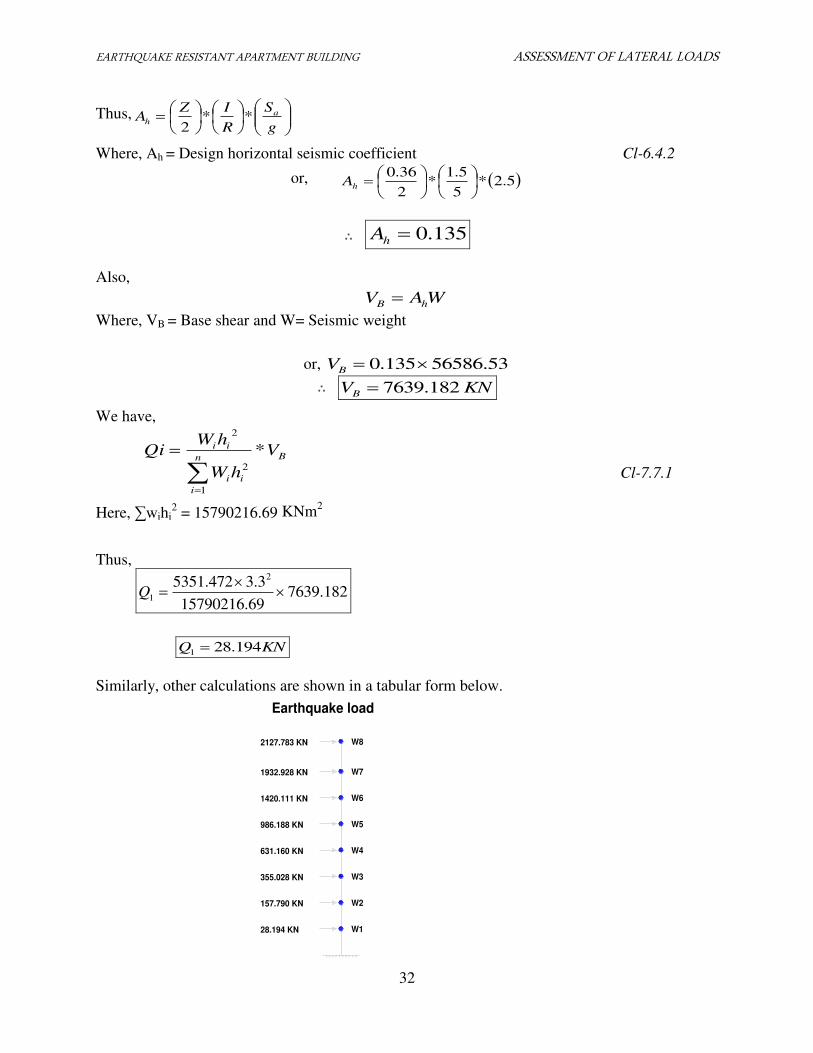
Similarly, other calculations are shown in a tabular form below.
W1
W2
W3
W4
W5
W6
W7
Earthquake load
28.194 KN
157.790 KN
355.028 KN
631.160 KN
986.188 KN
1420.111 KN
1932.928 KN
2127.783 KN W8
EARTHQUAKE RESISTANT APARTMENT BUILDING ASSESSMENT OF LATERAL LOADS
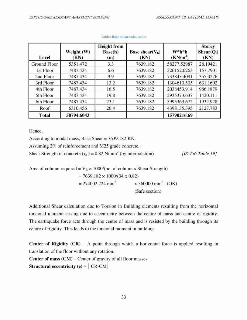
33
Table: Base shear calculation
Level
Weight (W)
(KN)
Height from
Base(h)
(m)
Base shear(Vb)
(KN)
W*h*h
(KN/m2)
Storey
Shear(Qi)
(KN)
Ground Floor 5351.472 3.3 7639.182 58277.52987 28.19421
1st Floor 7487.434 6.6 7639.182 326152.6263 157.7901
2nd Floor 7487.434 9.9 7639.182 733843.4091 355.0276
3rd Floor 7487.434 13.2 7639.182 1304610.505 631.1602
4th Floor 7487.434 16.5 7639.182 2038453.914 986.1879
5th Floor 7487.434 19.8 7639.182 2935373.637 1420.111
6th Floor 7487.434 23.1 7639.182 3995369.672 1932.928
Roof 6310.456 26.4 7639.182 4398135.395 2127.783
Total 50794.6043 15790216.69
Hence,
According to modal mass, Base Shear = 7639.182 KN.
Assuming 2% of reinforcement and M25 grade concrete,
Shear Strength of concrete (τc ) = 0.82 N/mm2 (by interpolation) [IS-456 Table 19]
Area of column required = VB × 1000/(no. of column x Shear Strength)
= 7639.182 × 1000/(34 x 0.82)
= 274002.224 mm2 < 360000 mm2 (OK)
(Safe section)
Additional Shear calculation due to Torsion in Building elements resulting from the horizontal
torsional moment arising due to eccentricity between the centre of mass and centre of rigidity.
The earthquake force acts through the centre of mass and is resisted by the building through its
centre of rigidity. This leads to the torsional moment in building.
Center of Rigidity (CR) – A point through which a horizontal force is applied resulting in
translation of the floor without any rotation.
Center of mass (CM) – Center of gravity of all floor masses.
Structural eccentricity (e) = │CR-CM│
EARTHQUAKE RESISTANT APARTMENT BUILDING CALCULATION OF C.M, C.R AND ECCENTRICITY
34
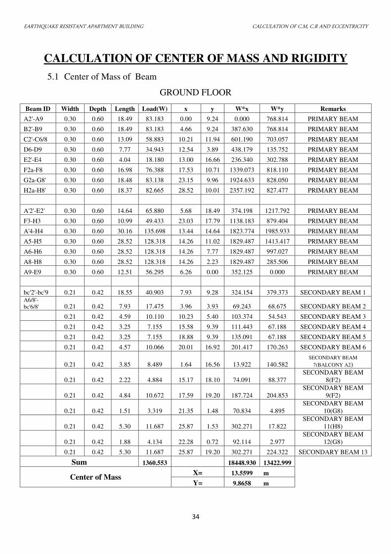
CALCULATION OF CENTER OF MASS AND RIGIDITY
5.1 Center of Mass of Beam
GROUND FLOOR
Beam ID Width Depth Length Load(W) x y W*x W*y Remarks
A2'-A9 0.30 0.60 18.49 83.183 0.00 9.24 0.000 768.814 PRIMARY BEAM
B2'-B9 0.30 0.60 18.49 83.183 4.66 9.24 387.630 768.814 PRIMARY BEAM
C2'-C6/8 0.30 0.60 13.09 58.883 10.21 11.94 601.190 703.057 PRIMARY BEAM
D6-D9 0.30 0.60 7.77 34.943 12.54 3.89 438.179 135.752 PRIMARY BEAM
E2'-E4 0.30 0.60 4.04 18.180 13.00 16.66 236.340 302.788 PRIMARY BEAM
F2a-F8 0.30 0.60 16.98 76.388 17.53 10.71 1339.073 818.110 PRIMARY BEAM
G2a-G8' 0.30 0.60 18.48 83.138 23.15 9.96 1924.633 828.050 PRIMARY BEAM
H2a-H8' 0.30 0.60 18.37 82.665 28.52 10.01 2357.192 827.477 PRIMARY BEAM
A'2'-E2' 0.30 0.60 14.64 65.880 5.68 18.49 374.198 1217.792 PRIMARY BEAM
F3-H3 0.30 0.60 10.99 49.433 23.03 17.79 1138.183 879.404 PRIMARY BEAM
A'4-H4 0.30 0.60 30.16 135.698 13.44 14.64 1823.774 1985.933 PRIMARY BEAM
A5-H5 0.30 0.60 28.52 128.318 14.26 11.02 1829.487 1413.417 PRIMARY BEAM
A6-H6 0.30 0.60 28.52 128.318 14.26 7.77 1829.487 997.027 PRIMARY BEAM
A8-H8 0.30 0.60 28.52 128.318 14.26 2.23 1829.487 285.506 PRIMARY BEAM
A9-E9 0.30 0.60 12.51 56.295 6.26 0.00 352.125 0.000 PRIMARY BEAM
bc'2'-bc'9 0.21 0.42 18.55 40.903 7.93 9.28 324.154 379.373 SECONDARY BEAM 1 A6/8'-
bc'6/8' 0.21 0.42 7.93 17.475 3.96 3.93 69.243 68.675 SECONDARY BEAM 2
0.21 0.42 4.59 10.110 10.23 5.40 103.374 54.543 SECONDARY BEAM 3
0.21 0.42 3.25 7.155 15.58 9.39 111.443 67.188 SECONDARY BEAM 4
0.21 0.42 3.25 7.155 18.88 9.39 135.091 67.188 SECONDARY BEAM 5
0.21 0.42 4.57 10.066 20.01 16.92 201.417 170.263 SECONDARY BEAM 6
0.21 0.42 3.85 8.489 1.64 16.56 13.922 140.582 SECONDARY BEAM
7(BALCONY A2)
0.21 0.42 2.22 4.884 15.17 18.10 74.091 88.377
SECONDARY BEAM
8(F2)
0.21 0.42 4.84 10.672 17.59 19.20 187.724 204.853
SECONDARY BEAM
9(F2)
0.21 0.42 1.51 3.319 21.35 1.48 70.834 4.895
SECONDARY BEAM
10(G8)
0.21 0.42 5.30 11.687 25.87 1.53 302.271 17.822
SECONDARY BEAM
11(H8)
0.21 0.42 1.88 4.134 22.28 0.72 92.114 2.977
SECONDARY BEAM
12(G8)
0.21 0.42 5.30 11.687 25.87 19.20 302.271 224.322 SECONDARY BEAM 13
Sum 1360.553 18448.930 13422.999
Center of Mass X= 13.5599 m
Y= 9.8658 m
EARTHQUAKE RESISTANT APARTMENT BUILDING CALCULATION OF C.M, C.R AND ECCENTRICITY
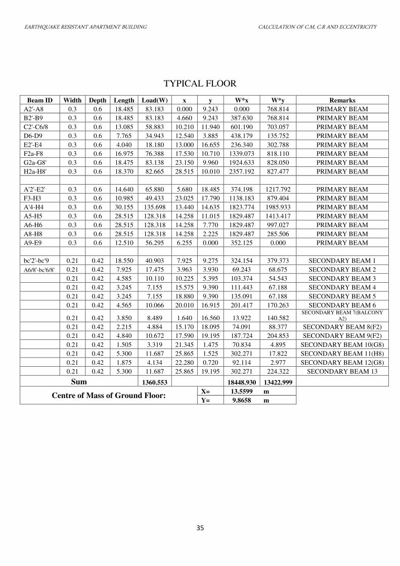
35
TYPICAL FLOOR
Beam ID Width Depth Length Load(W) x y W*x W*y Remarks
A2'-A8 0.3 0.6 18.485 83.183 0.000 9.243 0.000 768.814 PRIMARY BEAM
B2'-B9 0.3 0.6 18.485 83.183 4.660 9.243 387.630 768.814 PRIMARY BEAM
C2'-C6/8 0.3 0.6 13.085 58.883 10.210 11.940 601.190 703.057 PRIMARY BEAM
D6-D9 0.3 0.6 7.765 34.943 12.540 3.885 438.179 135.752 PRIMARY BEAM
E2'-E4 0.3 0.6 4.040 18.180 13.000 16.655 236.340 302.788 PRIMARY BEAM
F2a-F8 0.3 0.6 16.975 76.388 17.530 10.710 1339.073 818.110 PRIMARY BEAM
G2a-G8' 0.3 0.6 18.475 83.138 23.150 9.960 1924.633 828.050 PRIMARY BEAM
H2a-H8' 0.3 0.6 18.370 82.665 28.515 10.010 2357.192 827.477 PRIMARY BEAM
A'2'-E2' 0.3 0.6 14.640 65.880 5.680 18.485 374.198 1217.792 PRIMARY BEAM
F3-H3 0.3 0.6 10.985 49.433 23.025 17.790 1138.183 879.404 PRIMARY BEAM
A'4-H4 0.3 0.6 30.155 135.698 13.440 14.635 1823.774 1985.933 PRIMARY BEAM
A5-H5 0.3 0.6 28.515 128.318 14.258 11.015 1829.487 1413.417 PRIMARY BEAM
A6-H6 0.3 0.6 28.515 128.318 14.258 7.770 1829.487 997.027 PRIMARY BEAM
A8-H8 0.3 0.6 28.515 128.318 14.258 2.225 1829.487 285.506 PRIMARY BEAM
A9-E9 0.3 0.6 12.510 56.295 6.255 0.000 352.125 0.000 PRIMARY BEAM
bc'2'-bc'9 0.21 0.42 18.550 40.903 7.925 9.275 324.154 379.373 SECONDARY BEAM 1
A6/8'-bc'6/8' 0.21 0.42 7.925 17.475 3.963 3.930 69.243 68.675 SECONDARY BEAM 2
0.21 0.42 4.585 10.110 10.225 5.395 103.374 54.543 SECONDARY BEAM 3
0.21 0.42 3.245 7.155 15.575 9.390 111.443 67.188 SECONDARY BEAM 4
0.21 0.42 3.245 7.155 18.880 9.390 135.091 67.188 SECONDARY BEAM 5
0.21 0.42 4.565 10.066 20.010 16.915 201.417 170.263 SECONDARY BEAM 6
0.21 0.42 3.850 8.489 1.640 16.560 13.922 140.582 SECONDARY BEAM 7(BALCONY
A2)
0.21 0.42 2.215 4.884 15.170 18.095 74.091 88.377 SECONDARY BEAM 8(F2)
0.21 0.42 4.840 10.672 17.590 19.195 187.724 204.853 SECONDARY BEAM 9(F2)
0.21 0.42 1.505 3.319 21.345 1.475 70.834 4.895 SECONDARY BEAM 10(G8)
0.21 0.42 5.300 11.687 25.865 1.525 302.271 17.822 SECONDARY BEAM 11(H8)
0.21 0.42 1.875 4.134 22.280 0.720 92.114 2.977 SECONDARY BEAM 12(G8)
0.21 0.42 5.300 11.687 25.865 19.195 302.271 224.322 SECONDARY BEAM 13
Sum 1360.553 18448.930 13422.999
Centre of Mass of Ground Floor: X= 13.5599 m
Y= 9.8658 m
EARTHQUAKE RESISTANT APARTMENT BUILDING CALCULATION OF C.M, C.R AND ECCENTRICITY
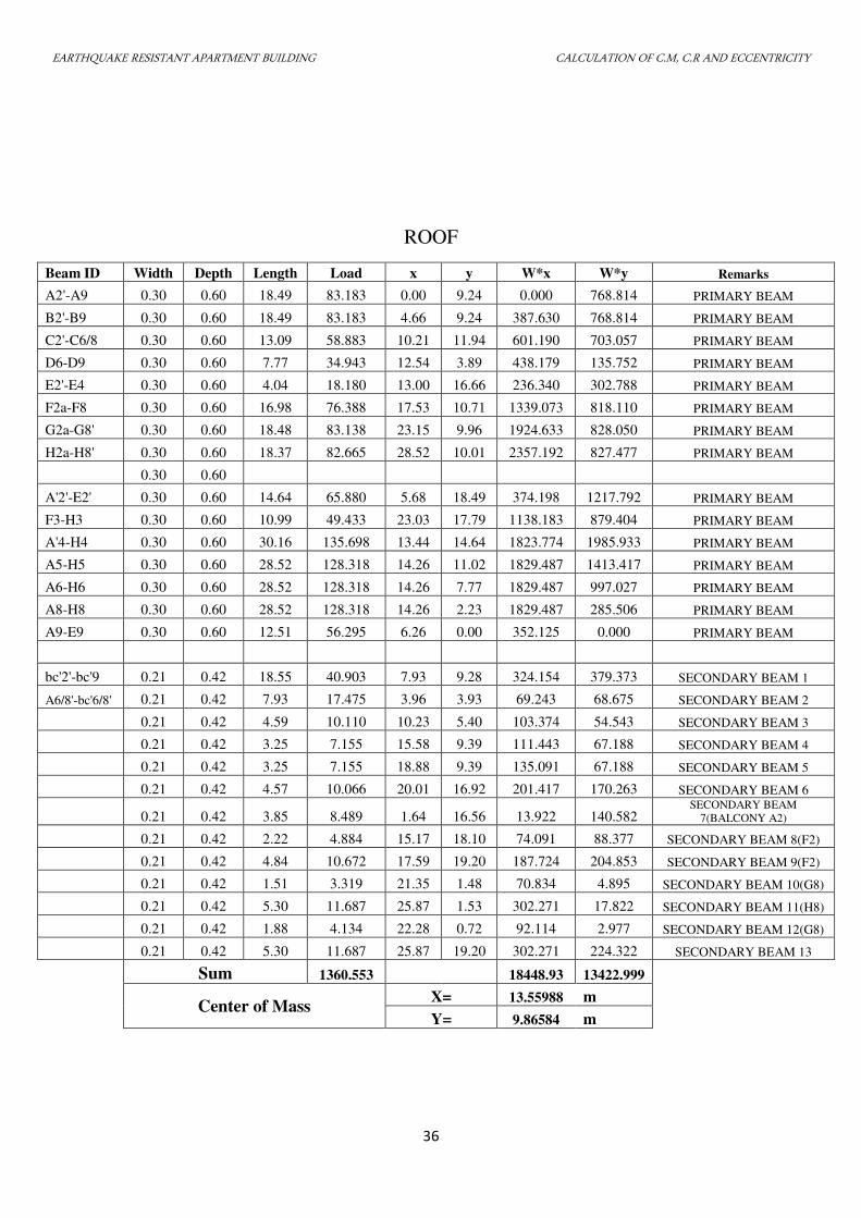
36
ROOF
Beam ID Width Depth Length Load x y W*x W*y Remarks
A2'-A9 0.30 0.60 18.49 83.183 0.00 9.24 0.000 768.814 PRIMARY BEAM
B2'-B9 0.30 0.60 18.49 83.183 4.66 9.24 387.630 768.814 PRIMARY BEAM
C2'-C6/8 0.30 0.60 13.09 58.883 10.21 11.94 601.190 703.057 PRIMARY BEAM
D6-D9 0.30 0.60 7.77 34.943 12.54 3.89 438.179 135.752 PRIMARY BEAM
E2'-E4 0.30 0.60 4.04 18.180 13.00 16.66 236.340 302.788 PRIMARY BEAM
F2a-F8 0.30 0.60 16.98 76.388 17.53 10.71 1339.073 818.110 PRIMARY BEAM
G2a-G8' 0.30 0.60 18.48 83.138 23.15 9.96 1924.633 828.050 PRIMARY BEAM
H2a-H8' 0.30 0.60 18.37 82.665 28.52 10.01 2357.192 827.477 PRIMARY BEAM
0.30 0.60
A'2'-E2' 0.30 0.60 14.64 65.880 5.68 18.49 374.198 1217.792 PRIMARY BEAM
F3-H3 0.30 0.60 10.99 49.433 23.03 17.79 1138.183 879.404 PRIMARY BEAM
A'4-H4 0.30 0.60 30.16 135.698 13.44 14.64 1823.774 1985.933 PRIMARY BEAM
A5-H5 0.30 0.60 28.52 128.318 14.26 11.02 1829.487 1413.417 PRIMARY BEAM
A6-H6 0.30 0.60 28.52 128.318 14.26 7.77 1829.487 997.027 PRIMARY BEAM
A8-H8 0.30 0.60 28.52 128.318 14.26 2.23 1829.487 285.506 PRIMARY BEAM
A9-E9 0.30 0.60 12.51 56.295 6.26 0.00 352.125 0.000 PRIMARY BEAM
bc'2'-bc'9 0.21 0.42 18.55 40.903 7.93 9.28 324.154 379.373 SECONDARY BEAM 1
A6/8'-bc'6/8' 0.21 0.42 7.93 17.475 3.96 3.93 69.243 68.675 SECONDARY BEAM 2
0.21 0.42 4.59 10.110 10.23 5.40 103.374 54.543 SECONDARY BEAM 3
0.21 0.42 3.25 7.155 15.58 9.39 111.443 67.188 SECONDARY BEAM 4
0.21 0.42 3.25 7.155 18.88 9.39 135.091 67.188 SECONDARY BEAM 5
0.21 0.42 4.57 10.066 20.01 16.92 201.417 170.263 SECONDARY BEAM 6
0.21 0.42 3.85 8.489 1.64 16.56 13.922 140.582 SECONDARY BEAM
7(BALCONY A2)
0.21 0.42 2.22 4.884 15.17 18.10 74.091 88.377 SECONDARY BEAM 8(F2)
0.21 0.42 4.84 10.672 17.59 19.20 187.724 204.853 SECONDARY BEAM 9(F2)
0.21 0.42 1.51 3.319 21.35 1.48 70.834 4.895 SECONDARY BEAM 10(G8)
0.21 0.42 5.30 11.687 25.87 1.53 302.271 17.822 SECONDARY BEAM 11(H8)
0.21 0.42 1.88 4.134 22.28 0.72 92.114 2.977 SECONDARY BEAM 12(G8)
0.21 0.42 5.30 11.687 25.87 19.20 302.271 224.322 SECONDARY BEAM 13
Sum 1360.553 18448.93 13422.999
Center of Mass X= 13.55988 m
Y= 9.86584 m
EARTHQUAKE RESISTANT APARTMENT BUILDING CALCULATION OF C.M, C.R AND ECCENTRICITY
37
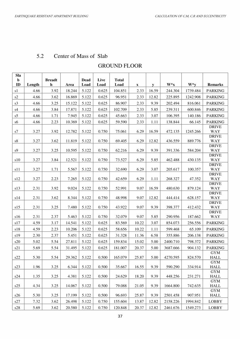
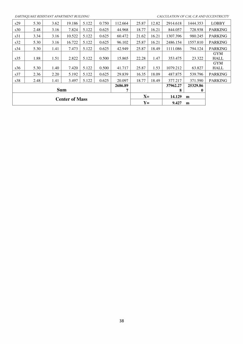
5.2 Center of Mass of Slab
GROUND FLOOR
Sla
b
ID Length
Breadt
h Area
Dead
Load
Live
Load
Total
Load x y W*x W*y Remarks
s1 4.66 3.92 18.244 5.122 0.625 104.851 2.33 16.59 244.304 1739.484 PARKING
s2 4.66 3.62 16.869 5.122 0.625 96.951 2.33 12.82 225.895 1242.908 PARKING
s3 4.66 3.25 15.122 5.122 0.625 86.907 2.33 9.39 202.494 816.061 PARKING
s4 4.66 3.84 17.871 5.122 0.625 102.709 2.33 5.85 239.311 600.846 PARKING
s5 4.66 1.71 7.945 5.122 0.625 45.663 2.33 3.07 106.395 140.186 PARKING
s6 4.66 2.23 10.369 5.122 0.625 59.590 2.33 1.11 138.844 66.145 PARKING
s7 3.27 3.92 12.782 5.122 0.750 75.061 6.29 16.59 472.135 1245.266
DRIVE
WAY
s8 3.27 3.62 11.819 5.122 0.750 69.405 6.29 12.82 436.559 889.776
DRIVE
WAY
s9 3.27 3.25 10.595 5.122 0.750 62.216 6.29 9.39 391.336 584.204
DRIVE
WAY
s10 3.27 3.84 12.521 5.122 0.750 73.527 6.29 5.85 462.488 430.135
DRIVE
WAY
s11 3.27 1.71 5.567 5.122 0.750 32.690 6.29 3.07 205.617 100.357
DRIVE
WAY
s12 3.27 2.23 7.265 5.122 0.750 42.659 6.29 1.11 268.327 47.352
DRIVE
WAY
s13 2.31 3.92 9.024 5.122 0.750 52.991 9.07 16.59 480.630 879.124
DRIVE
WAY
s14 2.31 3.62 8.344 5.122 0.750 48.998 9.07 12.82 444.414 628.157
DRIVE
WAY
s15 2.31 3.25 7.480 5.122 0.750 43.922 9.07 9.39 398.377 412.432
DRIVE
WAY
s16 2.31 2.37 5.463 5.122 0.750 32.079 9.07 5.85 290.956 187.662
DRIVE
WAY
s17 4.59 3.17 14.541 5.122 0.625 83.569 10.22 3.07 854.073 256.556 PARKING
s18 4.59 2.23 10.206 5.122 0.625 58.656 10.22 1.11 599.468 65.109 PARKING
s19 2.30 2.37 5.451 5.122 0.625 31.328 11.36 6.58 355.886 206.138 PARKING
s20 5.02 5.54 27.811 5.122 0.625 159.834 15.02 5.00 2400.710 798.372 PARKING
s21 5.69 5.54 31.495 5.122 0.625 181.007 20.37 5.00 3687.666 904.132 PARKING
s22 5.30 5.54 29.362 5.122 0.500 165.079 25.87 5.00 4270.595 824.570
GYM
HALL
s23 1.96 3.25 6.344 5.122 0.500 35.667 16.55 9.39 590.290 334.914
GYM
HALL
s24 1.35 3.25 4.381 5.122 0.500 24.629 18.20 9.39 448.256 231.271
GYM
HALL
s25 4.34 3.25 14.067 5.122 0.500 79.088 21.05 9.39 1664.800 742.635
GYM
HALL
s26 5.30 3.25 17.199 5.122 0.500 96.693 25.87 9.39 2501.458 907.951
GYM
HALL
s27 7.32 3.62 26.498 5.122 0.750 155.604 13.87 12.82 2158.226 1994.842 LOBBY
s28 5.69 3.62 20.580 5.122 0.750 120.848 20.37 12.82 2461.676 1549.273 LOBBY
EARTHQUAKE RESISTANT APARTMENT BUILDING CALCULATION OF C.M, C.R AND ECCENTRICITY
38
s29 5.30 3.62 19.186 5.122 0.750 112.664 25.87 12.82 2914.618 1444.353 LOBBY
s30 2.48 3.16 7.824 5.122 0.625 44.968 18.77 16.21 844.057 728.938 PARKING
s31 3.34 3.16 10.522 5.122 0.625 60.472 21.62 16.21 1307.396 980.245 PARKING
s32 5.30 3.16 16.722 5.122 0.625 96.102 25.87 16.21 2486.154 1557.810 PARKING
s34 5.30 1.41 7.473 5.122 0.625 42.949 25.87 18.49 1111.086 794.124 PARKING
s35 1.88 1.51 2.822 5.122 0.500 15.865 22.28 1.47 353.475 23.322
GYM
HALL
s36 5.30 1.40 7.420 5.122 0.500 41.717 25.87 1.53 1079.212 63.827
GYM
HALL
s37 2.36 2.20 5.192 5.122 0.625 29.839 16.35 18.09 487.875 539.796 PARKING
s38 2.48 1.41 3.497 5.122 0.625 20.097 18.77 18.49 377.217 371.590 PARKING
Sum 2686.89
7 37962.27
8
25329.86
0
Center of Mass X= 14.129 m
Y= 9.427 m
EARTHQUAKE RESISTANT APARTMENT BUILDING CALCULATION OF C.M, C.R AND ECCENTRICITY
39
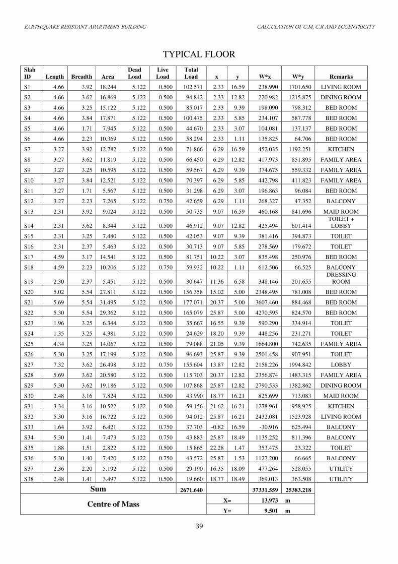
TYPICAL FLOOR
Slab
ID Length Breadth Area
Dead
Load
Live
Load
Total
Load x y W*x W*y Remarks
S1 4.66 3.92 18.244 5.122 0.500 102.571 2.33 16.59 238.990 1701.650 LIVING ROOM
S2 4.66 3.62 16.869 5.122 0.500 94.842 2.33 12.82 220.982 1215.875 DINING ROOM
S3 4.66 3.25 15.122 5.122 0.500 85.017 2.33 9.39 198.090 798.312 BED ROOM
S4 4.66 3.84 17.871 5.122 0.500 100.475 2.33 5.85 234.107 587.778 BED ROOM
S5 4.66 1.71 7.945 5.122 0.500 44.670 2.33 3.07 104.081 137.137 BED ROOM
S6 4.66 2.23 10.369 5.122 0.500 58.294 2.33 1.11 135.825 64.706 BED ROOM
S7 3.27 3.92 12.782 5.122 0.500 71.866 6.29 16.59 452.035 1192.251 KITCHEN
S8 3.27 3.62 11.819 5.122 0.500 66.450 6.29 12.82 417.973 851.895 FAMILY AREA
S9 3.27 3.25 10.595 5.122 0.500 59.567 6.29 9.39 374.675 559.332 FAMILY AREA
S10 3.27 3.84 12.521 5.122 0.500 70.397 6.29 5.85 442.798 411.823 FAMILY AREA
S11 3.27 1.71 5.567 5.122 0.500 31.298 6.29 3.07 196.863 96.084 BED ROOM
S12 3.27 2.23 7.265 5.122 0.750 42.659 6.29 1.11 268.327 47.352 BALCONY
S13 2.31 3.92 9.024 5.122 0.500 50.735 9.07 16.59 460.168 841.696 MAID ROOM
S14 2.31 3.62 8.344 5.122 0.500 46.912 9.07 12.82 425.494 601.414
TOILET +
LOBBY
S15 2.31 3.25 7.480 5.122 0.500 42.053 9.07 9.39 381.416 394.873 TOILET
S16 2.31 2.37 5.463 5.122 0.500 30.713 9.07 5.85 278.569 179.672 TOILET
S17 4.59 3.17 14.541 5.122 0.500 81.751 10.22 3.07 835.498 250.976 BED ROOM
S18 4.59 2.23 10.206 5.122 0.750 59.932 10.22 1.11 612.506 66.525 BALCONY
S19 2.30 2.37 5.451 5.122 0.500 30.647 11.36 6.58 348.146 201.655
DRESSING
ROOM
S20 5.02 5.54 27.811 5.122 0.500 156.358 15.02 5.00 2348.495 781.008 BED ROOM
S21 5.69 5.54 31.495 5.122 0.500 177.071 20.37 5.00 3607.460 884.468 BED ROOM
S22 5.30 5.54 29.362 5.122 0.500 165.079 25.87 5.00 4270.595 824.570 BED ROOM
S23 1.96 3.25 6.344 5.122 0.500 35.667 16.55 9.39 590.290 334.914 TOILET
S24 1.35 3.25 4.381 5.122 0.500 24.629 18.20 9.39 448.256 231.271 TOILET
S25 4.34 3.25 14.067 5.122 0.500 79.088 21.05 9.39 1664.800 742.635 FAMILY AREA
S26 5.30 3.25 17.199 5.122 0.500 96.693 25.87 9.39 2501.458 907.951 TOILET
S27 7.32 3.62 26.498 5.122 0.750 155.604 13.87 12.82 2158.226 1994.842 LOBBY
S28 5.69 3.62 20.580 5.122 0.500 115.703 20.37 12.82 2356.874 1483.315 FAMILY AREA
S29 5.30 3.62 19.186 5.122 0.500 107.868 25.87 12.82 2790.533 1382.862 DINING ROOM
S30 2.48 3.16 7.824 5.122 0.500 43.990 18.77 16.21 825.699 713.083 MAID ROOM
S31 3.34 3.16 10.522 5.122 0.500 59.156 21.62 16.21 1278.961 958.925 KITCHEN
S32 5.30 3.16 16.722 5.122 0.500 94.012 25.87 16.21 2432.081 1523.928 LIVING ROOM
S33 1.64 3.92 6.421 5.122 0.750 37.703 -0.82 16.59 -30.916 625.494 BALCONY
S34 5.30 1.41 7.473 5.122 0.750 43.883 25.87 18.49 1135.252 811.396 BALCONY
S35 1.88 1.51 2.822 5.122 0.500 15.865 22.28 1.47 353.475 23.322 TOILET
S36 5.30 1.40 7.420 5.122 0.750 43.572 25.87 1.53 1127.200 66.665 BALCONY
S37 2.36 2.20 5.192 5.122 0.500 29.190 16.35 18.09 477.264 528.055 UTILITY
S38 2.48 1.41 3.497 5.122 0.500 19.660 18.77 18.49 369.013 363.508 UTILITY
Sum 2671.640 37331.559 25383.218
Centre of Mass X= 13.973 m
Y= 9.501 m
EARTHQUAKE RESISTANT APARTMENT BUILDING CALCULATION OF C.M, C.R AND ECCENTRICITY
40
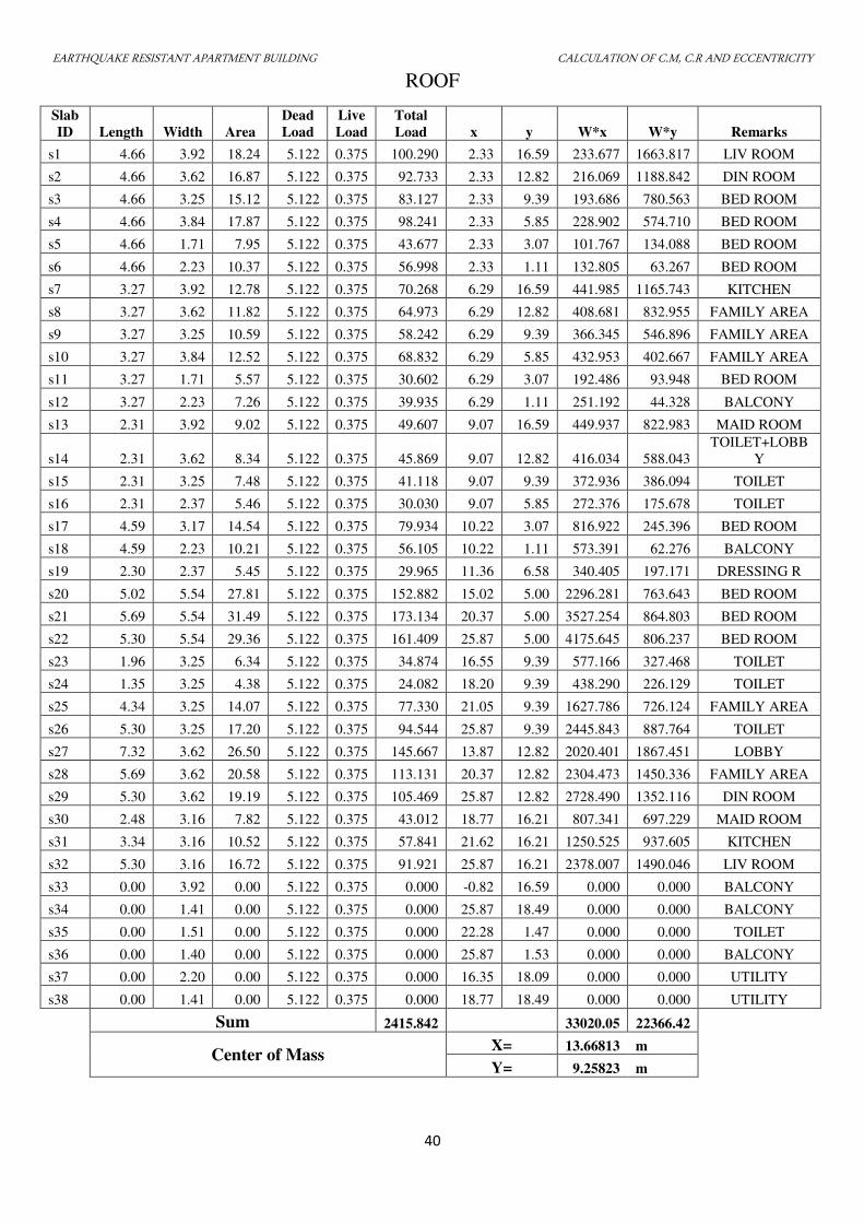
ROOF
Slab
ID Length Width Area
Dead
Load
Live
Load
Total
Load x y W*x W*y Remarks
s1 4.66 3.92 18.24 5.122 0.375 100.290 2.33 16.59 233.677 1663.817 LIV ROOM
s2 4.66 3.62 16.87 5.122 0.375 92.733 2.33 12.82 216.069 1188.842 DIN ROOM
s3 4.66 3.25 15.12 5.122 0.375 83.127 2.33 9.39 193.686 780.563 BED ROOM
s4 4.66 3.84 17.87 5.122 0.375 98.241 2.33 5.85 228.902 574.710 BED ROOM
s5 4.66 1.71 7.95 5.122 0.375 43.677 2.33 3.07 101.767 134.088 BED ROOM
s6 4.66 2.23 10.37 5.122 0.375 56.998 2.33 1.11 132.805 63.267 BED ROOM
s7 3.27 3.92 12.78 5.122 0.375 70.268 6.29 16.59 441.985 1165.743 KITCHEN
s8 3.27 3.62 11.82 5.122 0.375 64.973 6.29 12.82 408.681 832.955 FAMILY AREA
s9 3.27 3.25 10.59 5.122 0.375 58.242 6.29 9.39 366.345 546.896 FAMILY AREA
s10 3.27 3.84 12.52 5.122 0.375 68.832 6.29 5.85 432.953 402.667 FAMILY AREA
s11 3.27 1.71 5.57 5.122 0.375 30.602 6.29 3.07 192.486 93.948 BED ROOM
s12 3.27 2.23 7.26 5.122 0.375 39.935 6.29 1.11 251.192 44.328 BALCONY
s13 2.31 3.92 9.02 5.122 0.375 49.607 9.07 16.59 449.937 822.983 MAID ROOM
s14 2.31 3.62 8.34 5.122 0.375 45.869 9.07 12.82 416.034 588.043
TOILET+LOBB
Y
s15 2.31 3.25 7.48 5.122 0.375 41.118 9.07 9.39 372.936 386.094 TOILET
s16 2.31 2.37 5.46 5.122 0.375 30.030 9.07 5.85 272.376 175.678 TOILET
s17 4.59 3.17 14.54 5.122 0.375 79.934 10.22 3.07 816.922 245.396 BED ROOM
s18 4.59 2.23 10.21 5.122 0.375 56.105 10.22 1.11 573.391 62.276 BALCONY
s19 2.30 2.37 5.45 5.122 0.375 29.965 11.36 6.58 340.405 197.171 DRESSING R
s20 5.02 5.54 27.81 5.122 0.375 152.882 15.02 5.00 2296.281 763.643 BED ROOM
s21 5.69 5.54 31.49 5.122 0.375 173.134 20.37 5.00 3527.254 864.803 BED ROOM
s22 5.30 5.54 29.36 5.122 0.375 161.409 25.87 5.00 4175.645 806.237 BED ROOM
s23 1.96 3.25 6.34 5.122 0.375 34.874 16.55 9.39 577.166 327.468 TOILET
s24 1.35 3.25 4.38 5.122 0.375 24.082 18.20 9.39 438.290 226.129 TOILET
s25 4.34 3.25 14.07 5.122 0.375 77.330 21.05 9.39 1627.786 726.124 FAMILY AREA
s26 5.30 3.25 17.20 5.122 0.375 94.544 25.87 9.39 2445.843 887.764 TOILET
s27 7.32 3.62 26.50 5.122 0.375 145.667 13.87 12.82 2020.401 1867.451 LOBBY
s28 5.69 3.62 20.58 5.122 0.375 113.131 20.37 12.82 2304.473 1450.336 FAMILY AREA
s29 5.30 3.62 19.19 5.122 0.375 105.469 25.87 12.82 2728.490 1352.116 DIN ROOM
s30 2.48 3.16 7.82 5.122 0.375 43.012 18.77 16.21 807.341 697.229 MAID ROOM
s31 3.34 3.16 10.52 5.122 0.375 57.841 21.62 16.21 1250.525 937.605 KITCHEN
s32 5.30 3.16 16.72 5.122 0.375 91.921 25.87 16.21 2378.007 1490.046 LIV ROOM
s33 0.00 3.92 0.00 5.122 0.375 0.000 -0.82 16.59 0.000 0.000 BALCONY
s34 0.00 1.41 0.00 5.122 0.375 0.000 25.87 18.49 0.000 0.000 BALCONY
s35 0.00 1.51 0.00 5.122 0.375 0.000 22.28 1.47 0.000 0.000 TOILET
s36 0.00 1.40 0.00 5.122 0.375 0.000 25.87 1.53 0.000 0.000 BALCONY
s37 0.00 2.20 0.00 5.122 0.375 0.000 16.35 18.09 0.000 0.000 UTILITY
s38 0.00 1.41 0.00 5.122 0.375 0.000 18.77 18.49 0.000 0.000 UTILITY
Sum 2415.842 33020.05 22366.42
Center of Mass X= 13.66813 m
Y= 9.25823 m
EARTHQUAKE RESISTANT APARTMENT BUILDING CALCULATION OF C.M, C.R AND ECCENTRICITY
41
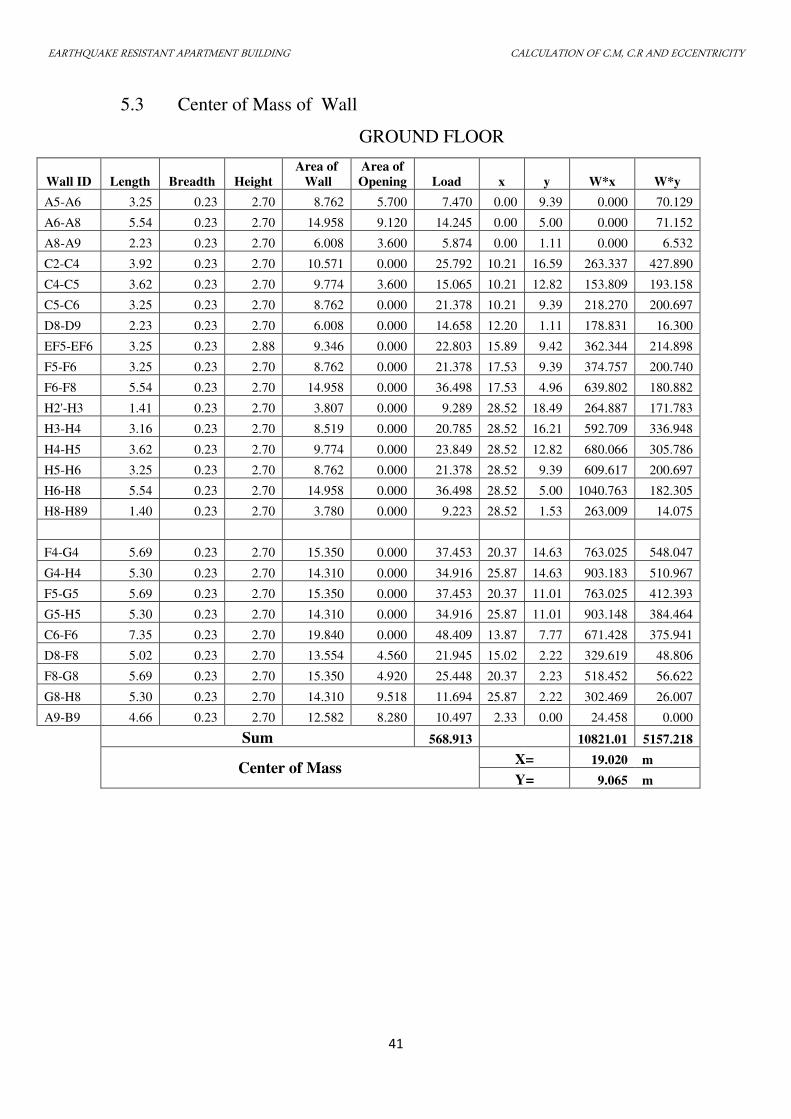
5.3 Center of Mass of Wall
GROUND FLOOR
Wall ID Length Breadth Height
Area of
Wall
Area of
Opening Load x y W*x W*y
A5-A6 3.25 0.23 2.70 8.762 5.700 7.470 0.00 9.39 0.000 70.129
A6-A8 5.54 0.23 2.70 14.958 9.120 14.245 0.00 5.00 0.000 71.152
A8-A9 2.23 0.23 2.70 6.008 3.600 5.874 0.00 1.11 0.000 6.532
C2-C4 3.92 0.23 2.70 10.571 0.000 25.792 10.21 16.59 263.337 427.890
C4-C5 3.62 0.23 2.70 9.774 3.600 15.065 10.21 12.82 153.809 193.158
C5-C6 3.25 0.23 2.70 8.762 0.000 21.378 10.21 9.39 218.270 200.697
D8-D9 2.23 0.23 2.70 6.008 0.000 14.658 12.20 1.11 178.831 16.300
EF5-EF6 3.25 0.23 2.88 9.346 0.000 22.803 15.89 9.42 362.344 214.898
F5-F6 3.25 0.23 2.70 8.762 0.000 21.378 17.53 9.39 374.757 200.740
F6-F8 5.54 0.23 2.70 14.958 0.000 36.498 17.53 4.96 639.802 180.882
H2'-H3 1.41 0.23 2.70 3.807 0.000 9.289 28.52 18.49 264.887 171.783
H3-H4 3.16 0.23 2.70 8.519 0.000 20.785 28.52 16.21 592.709 336.948
H4-H5 3.62 0.23 2.70 9.774 0.000 23.849 28.52 12.82 680.066 305.786
H5-H6 3.25 0.23 2.70 8.762 0.000 21.378 28.52 9.39 609.617 200.697
H6-H8 5.54 0.23 2.70 14.958 0.000 36.498 28.52 5.00 1040.763 182.305
H8-H89 1.40 0.23 2.70 3.780 0.000 9.223 28.52 1.53 263.009 14.075
F4-G4 5.69 0.23 2.70 15.350 0.000 37.453 20.37 14.63 763.025 548.047
G4-H4 5.30 0.23 2.70 14.310 0.000 34.916 25.87 14.63 903.183 510.967
F5-G5 5.69 0.23 2.70 15.350 0.000 37.453 20.37 11.01 763.025 412.393
G5-H5 5.30 0.23 2.70 14.310 0.000 34.916 25.87 11.01 903.148 384.464
C6-F6 7.35 0.23 2.70 19.840 0.000 48.409 13.87 7.77 671.428 375.941
D8-F8 5.02 0.23 2.70 13.554 4.560 21.945 15.02 2.22 329.619 48.806
F8-G8 5.69 0.23 2.70 15.350 4.920 25.448 20.37 2.23 518.452 56.622
G8-H8 5.30 0.23 2.70 14.310 9.518 11.694 25.87 2.22 302.469 26.007
A9-B9 4.66 0.23 2.70 12.582 8.280 10.497 2.33 0.00 24.458 0.000
Sum 568.913 10821.01 5157.218
Center of Mass X= 19.020 m
Y= 9.065 m
EARTHQUAKE RESISTANT APARTMENT BUILDING CALCULATION OF C.M, C.R AND ECCENTRICITY
42
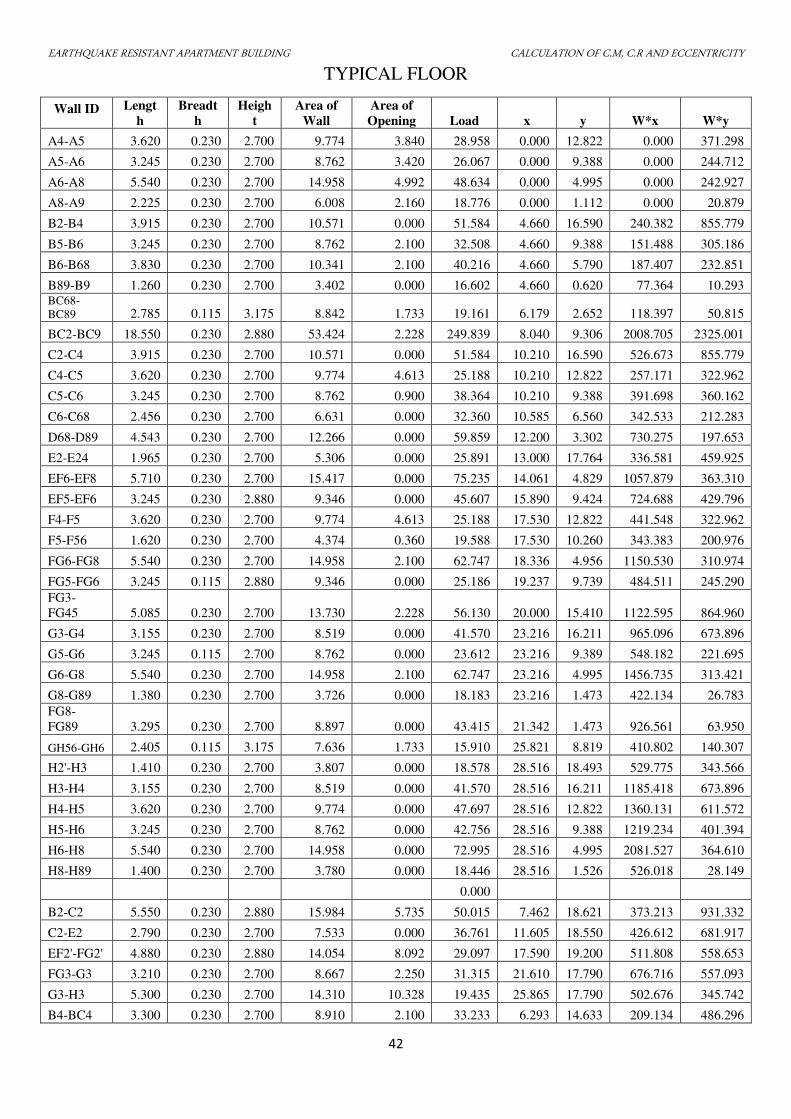
TYPICAL FLOOR
Wall ID Lengt
h
Breadt
h
Heigh
t
Area of
Wall
Area of
Opening Load x y W*x W*y
A4-A5 3.620 0.230 2.700 9.774 3.840 28.958 0.000 12.822 0.000 371.298
A5-A6 3.245 0.230 2.700 8.762 3.420 26.067 0.000 9.388 0.000 244.712
A6-A8 5.540 0.230 2.700 14.958 4.992 48.634 0.000 4.995 0.000 242.927
A8-A9 2.225 0.230 2.700 6.008 2.160 18.776 0.000 1.112 0.000 20.879
B2-B4 3.915 0.230 2.700 10.571 0.000 51.584 4.660 16.590 240.382 855.779
B5-B6 3.245 0.230 2.700 8.762 2.100 32.508 4.660 9.388 151.488 305.186
B6-B68 3.830 0.230 2.700 10.341 2.100 40.216 4.660 5.790 187.407 232.851
B89-B9 1.260 0.230 2.700 3.402 0.000 16.602 4.660 0.620 77.364 10.293 BC68-
BC89 2.785 0.115 3.175 8.842 1.733 19.161 6.179 2.652 118.397 50.815
BC2-BC9 18.550 0.230 2.880 53.424 2.228 249.839 8.040 9.306 2008.705 2325.001
C2-C4 3.915 0.230 2.700 10.571 0.000 51.584 10.210 16.590 526.673 855.779
C4-C5 3.620 0.230 2.700 9.774 4.613 25.188 10.210 12.822 257.171 322.962
C5-C6 3.245 0.230 2.700 8.762 0.900 38.364 10.210 9.388 391.698 360.162
C6-C68 2.456 0.230 2.700 6.631 0.000 32.360 10.585 6.560 342.533 212.283
D68-D89 4.543 0.230 2.700 12.266 0.000 59.859 12.200 3.302 730.275 197.653
E2-E24 1.965 0.230 2.700 5.306 0.000 25.891 13.000 17.764 336.581 459.925
EF6-EF8 5.710 0.230 2.700 15.417 0.000 75.235 14.061 4.829 1057.879 363.310
EF5-EF6 3.245 0.230 2.880 9.346 0.000 45.607 15.890 9.424 724.688 429.796
F4-F5 3.620 0.230 2.700 9.774 4.613 25.188 17.530 12.822 441.548 322.962
F5-F56 1.620 0.230 2.700 4.374 0.360 19.588 17.530 10.260 343.383 200.976
FG6-FG8 5.540 0.230 2.700 14.958 2.100 62.747 18.336 4.956 1150.530 310.974
FG5-FG6 3.245 0.115 2.880 9.346 0.000 25.186 19.237 9.739 484.511 245.290
FG3-
FG45 5.085 0.230 2.700 13.730 2.228 56.130 20.000 15.410 1122.595 864.960
G3-G4 3.155 0.230 2.700 8.519 0.000 41.570 23.216 16.211 965.096 673.896
G5-G6 3.245 0.115 2.700 8.762 0.000 23.612 23.216 9.389 548.182 221.695
G6-G8 5.540 0.230 2.700 14.958 2.100 62.747 23.216 4.995 1456.735 313.421
G8-G89 1.380 0.230 2.700 3.726 0.000 18.183 23.216 1.473 422.134 26.783
FG8-
FG89 3.295 0.230 2.700 8.897 0.000 43.415 21.342 1.473 926.561 63.950
GH56-GH6 2.405 0.115 3.175 7.636 1.733 15.910 25.821 8.819 410.802 140.307
H2'-H3 1.410 0.230 2.700 3.807 0.000 18.578 28.516 18.493 529.775 343.566
H3-H4 3.155 0.230 2.700 8.519 0.000 41.570 28.516 16.211 1185.418 673.896
H4-H5 3.620 0.230 2.700 9.774 0.000 47.697 28.516 12.822 1360.131 611.572
H5-H6 3.245 0.230 2.700 8.762 0.000 42.756 28.516 9.388 1219.234 401.394
H6-H8 5.540 0.230 2.700 14.958 0.000 72.995 28.516 4.995 2081.527 364.610
H8-H89 1.400 0.230 2.700 3.780 0.000 18.446 28.516 1.526 526.018 28.149
0.000
B2-C2 5.550 0.230 2.880 15.984 5.735 50.015 7.462 18.621 373.213 931.332
C2-E2 2.790 0.230 2.700 7.533 0.000 36.761 11.605 18.550 426.612 681.917
EF2'-FG2' 4.880 0.230 2.880 14.054 8.092 29.097 17.590 19.200 511.808 558.653
FG3-G3 3.210 0.230 2.700 8.667 2.250 31.315 21.610 17.790 676.716 557.093
G3-H3 5.300 0.230 2.700 14.310 10.328 19.435 25.865 17.790 502.676 345.742
B4-BC4 3.300 0.230 2.700 8.910 2.100 33.233 6.293 14.633 209.134 486.296
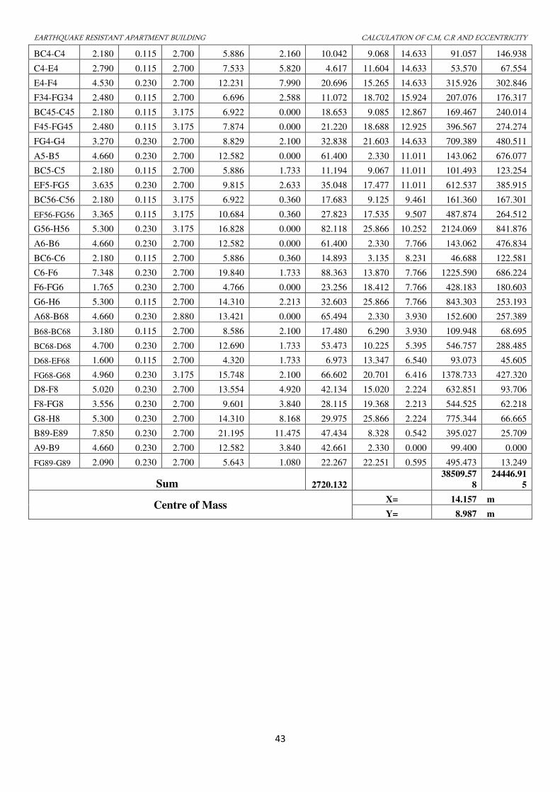
EARTHQUAKE RESISTANT APARTMENT BUILDING CALCULATION OF C.M, C.R AND ECCENTRICITY
43
BC4-C4 2.180 0.115 2.700 5.886 2.160 10.042 9.068 14.633 91.057 146.938
C4-E4 2.790 0.115 2.700 7.533 5.820 4.617 11.604 14.633 53.570 67.554
E4-F4 4.530 0.230 2.700 12.231 7.990 20.696 15.265 14.633 315.926 302.846
F34-FG34 2.480 0.115 2.700 6.696 2.588 11.072 18.702 15.924 207.076 176.317
BC45-C45 2.180 0.115 3.175 6.922 0.000 18.653 9.085 12.867 169.467 240.014
F45-FG45 2.480 0.115 3.175 7.874 0.000 21.220 18.688 12.925 396.567 274.274
FG4-G4 3.270 0.230 2.700 8.829 2.100 32.838 21.603 14.633 709.389 480.511
A5-B5 4.660 0.230 2.700 12.582 0.000 61.400 2.330 11.011 143.062 676.077
BC5-C5 2.180 0.115 2.700 5.886 1.733 11.194 9.067 11.011 101.493 123.254
EF5-FG5 3.635 0.230 2.700 9.815 2.633 35.048 17.477 11.011 612.537 385.915
BC56-C56 2.180 0.115 3.175 6.922 0.360 17.683 9.125 9.461 161.360 167.301
EF56-FG56 3.365 0.115 3.175 10.684 0.360 27.823 17.535 9.507 487.874 264.512
G56-H56 5.300 0.230 3.175 16.828 0.000 82.118 25.866 10.252 2124.069 841.876
A6-B6 4.660 0.230 2.700 12.582 0.000 61.400 2.330 7.766 143.062 476.834
BC6-C6 2.180 0.115 2.700 5.886 0.360 14.893 3.135 8.231 46.688 122.581
C6-F6 7.348 0.230 2.700 19.840 1.733 88.363 13.870 7.766 1225.590 686.224
F6-FG6 1.765 0.230 2.700 4.766 0.000 23.256 18.412 7.766 428.183 180.603
G6-H6 5.300 0.115 2.700 14.310 2.213 32.603 25.866 7.766 843.303 253.193
A68-B68 4.660 0.230 2.880 13.421 0.000 65.494 2.330 3.930 152.600 257.389
B68-BC68 3.180 0.115 2.700 8.586 2.100 17.480 6.290 3.930 109.948 68.695
BC68-D68 4.700 0.230 2.700 12.690 1.733 53.473 10.225 5.395 546.757 288.485
D68-EF68 1.600 0.115 2.700 4.320 1.733 6.973 13.347 6.540 93.073 45.605
FG68-G68 4.960 0.230 3.175 15.748 2.100 66.602 20.701 6.416 1378.733 427.320
D8-F8 5.020 0.230 2.700 13.554 4.920 42.134 15.020 2.224 632.851 93.706
F8-FG8 3.556 0.230 2.700 9.601 3.840 28.115 19.368 2.213 544.525 62.218
G8-H8 5.300 0.230 2.700 14.310 8.168 29.975 25.866 2.224 775.344 66.665
B89-E89 7.850 0.230 2.700 21.195 11.475 47.434 8.328 0.542 395.027 25.709
A9-B9 4.660 0.230 2.700 12.582 3.840 42.661 2.330 0.000 99.400 0.000
FG89-G89 2.090 0.230 2.700 5.643 1.080 22.267 22.251 0.595 495.473 13.249
Sum 2720.132
38509.57
8
24446.91
5
Centre of Mass X= 14.157 m
Y= 8.987 m
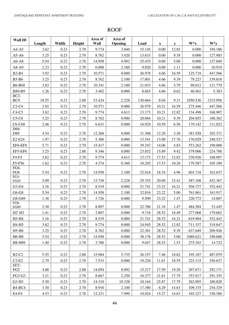
EARTHQUAKE RESISTANT APARTMENT BUILDING CALCULATION OF C.M, C.R AND ECCENTRICITY
44
ROOF
Wall ID Length Width Height
Area of
Wall
Area of
Opening Load x y W*x W*y
A4-A5 3.62 0.23 2.70 9.774 3.840 15.145 0.00 12.82 0.000 194.186
A5-A6 3.25 0.23 2.70 8.762 3.420 13.633 0.00 9.39 0.000 127.983
A6-A8 5.54 0.23 2.70 14.958 4.992 25.435 0.00 5.00 0.000 127.049
A8-A9 2.23 0.23 2.70 6.008 2.160 9.820 0.00 1.11 0.000 10.919
B2-B4 3.92 0.23 2.70 10.571 0.000 26.978 4.66 16.59 125.718 447.566
B5-B6 3.25 0.23 2.70 8.762 2.100 17.001 4.66 9.39 79.227 159.610
B6-B68 3.83 0.23 2.70 10.341 2.100 21.033 4.66 5.79 98.012 121.779
B89-B9 1.26 0.23 2.70 3.402 0.000 8.683 4.66 0.62 40.461 5.383
BC2-
BC9 18.55 0.23 2.88 53.424 2.228 130.664 8.04 9.31 1050.536 1215.956
C2-C4 3.92 0.23 2.70 10.571 0.000 26.978 10.21 16.59 275.446 447.566
C4-C5 3.62 0.23 2.70 9.774 4.613 13.173 10.21 12.82 134.498 168.907
C5-C6 3.25 0.23 2.70 8.762 0.900 20.064 10.21 9.39 204.855 188.362
C6-C68 2.46 0.23 2.70 6.631 0.000 16.924 10.59 6.56 179.142 111.022
D68-
D89 4.54 0.23 2.70 12.266 0.000 31.306 12.20 3.30 381.928 103.371
E2-E24 1.97 0.23 2.70 5.306 0.000 13.541 13.00 17.76 176.029 240.537
EF6-EF8 5.71 0.23 2.70 15.417 0.000 39.347 14.06 4.83 553.262 190.008
EF5-EF6 3.25 0.23 2.88 9.346 0.000 23.852 15.89 9.42 379.006 224.780
F4-F5 3.62 0.23 2.70 9.774 4.613 13.173 17.53 12.82 230.926 168.907
F5-F56 1.62 0.23 2.70 4.374 0.360 10.245 17.53 10.26 179.587 105.109
FG6-
FG8 5.54 0.23 2.70 14.958 2.100 32.816 18.34 4.96 601.718 162.637 FG3-
FG45 5.09 0.23 2.70 13.730 2.228 29.355 20.00 15.41 587.108 452.367
G3-G4 3.16 0.23 2.70 8.519 0.000 21.741 23.22 16.21 504.737 352.442
G6-G8 5.54 0.23 2.70 14.958 2.100 32.816 23.22 5.00 761.861 163.917
G8-G89 1.38 0.23 2.70 3.726 0.000 9.509 23.22 1.47 220.772 14.007 FG8-
FG89 3.30 0.23 2.70 8.897 0.000 22.706 21.34 1.47 484.584 33.445
H2'-H3 1.41 0.23 2.70 3.807 0.000 9.716 28.52 18.49 277.068 179.682
H3-H4 3.16 0.23 2.70 8.519 0.000 21.741 28.52 16.21 619.964 352.442
H4-H5 3.62 0.23 2.70 9.774 0.000 24.945 28.52 12.82 711.337 319.847
H5-H6 3.25 0.23 2.70 8.762 0.000 22.361 28.52 9.39 637.649 209.926
H6-H8 5.54 0.23 2.70 14.958 0.000 38.176 28.52 5.00 1088.621 190.688
H8-H89 1.40 0.23 2.70 3.780 0.000 9.647 28.52 1.53 275.103 14.722
B2-C2 5.55 0.23 2.88 15.984 5.735 26.157 7.46 18.62 195.187 487.079
C2-E2 2.79 0.23 2.70 7.533 0.000 19.226 11.61 18.55 223.115 356.637
EF2'-
FG2' 4.88 0.23 2.88 14.054 8.092 15.217 17.59 19.20 267.671 292.171
FG3-G3 3.21 0.23 2.70 8.667 2.250 16.377 21.61 17.79 353.917 291.355
G3-H3 5.30 0.23 2.70 14.310 10.328 10.164 25.87 17.79 262.895 180.820
B4-BC4 3.30 0.23 2.70 8.910 2.100 17.380 6.29 14.63 109.375 254.329
E4-F4 4.53 0.23 2.70 12.231 7.990 10.824 15.27 14.63 165.227 158.386
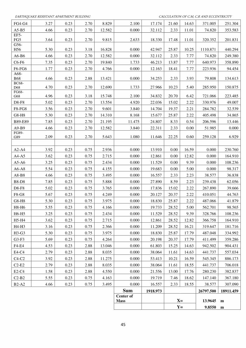
EARTHQUAKE RESISTANT APARTMENT BUILDING CALCULATION OF C.M, C.R AND ECCENTRICITY
45
FG4-G4 3.27 0.23 2.70 8.829 2.100 17.174 21.60 14.63 371.005 251.304
A5-B5 4.66 0.23 2.70 12.582 0.000 32.112 2.33 11.01 74.820 353.583
EF5-
FG5 3.64 0.23 2.70 9.815 2.633 18.330 17.48 11.01 320.352 201.831
G56-
H56 5.30 0.23 3.18 16.828 0.000 42.947 25.87 10.25 1110.871 440.294
A6-B6 4.66 0.23 2.70 12.582 0.000 32.112 2.33 7.77 74.820 249.380
C6-F6 7.35 0.23 2.70 19.840 1.733 46.213 13.87 7.77 640.973 358.890
F6-FG6 1.77 0.23 2.70 4.766 0.000 12.163 18.41 7.77 223.936 94.454
A68-
B68 4.66 0.23 2.88 13.421 0.000 34.253 2.33 3.93 79.808 134.613 BC68-
D68 4.70 0.23 2.70 12.690 1.733 27.966 10.23 5.40 285.950 150.875 FG68-
G68 4.96 0.23 3.18 15.748 2.100 34.832 20.70 6.42 721.066 223.485
D8-F8 5.02 0.23 2.70 13.554 4.920 22.036 15.02 2.22 330.976 49.007
F8-FG8 3.56 0.23 2.70 9.601 3.840 14.704 19.37 2.21 284.782 32.539
G8-H8 5.30 0.23 2.70 14.310 8.168 15.677 25.87 2.22 405.498 34.865
B89-E89 7.85 0.23 2.70 21.195 11.475 24.807 8.33 0.54 206.596 13.446
A9-B9 4.66 0.23 2.70 12.582 3.840 22.311 2.33 0.00 51.985 0.000 FG89-
G89 2.09 0.23 2.70 5.643 1.080 11.646 22.25 0.60 259.128 6.929
A2-A4 3.92 0.23 0.75 2.936 0.000 13.910 0.00 16.59 0.000 230.760
A4-A5 3.62 0.23 0.75 2.715 0.000 12.861 0.00 12.82 0.000 164.910
A5-A6 3.25 0.23 0.75 2.434 0.000 11.529 0.00 9.39 0.000 108.236
A6-A8 5.54 0.23 0.75 4.155 0.000 19.683 0.00 5.00 0.000 98.317
A8-B8 4.66 0.23 0.75 3.495 0.000 16.557 2.33 2.23 38.577 36.838
B8-D8 7.85 0.23 0.75 5.888 0.000 27.890 8.59 2.23 239.438 62.056
D8-F8 5.02 0.23 0.75 3.765 0.000 17.836 15.02 2.22 267.890 39.666
F8-G8 5.67 0.23 0.75 4.249 0.000 20.127 20.37 2.22 410.051 44.763
G8-H8 5.30 0.23 0.75 3.975 0.000 18.830 25.87 2.22 487.066 41.879
H8-H6 5.55 0.23 0.75 4.166 0.000 19.733 28.52 5.00 562.701 98.565
H6-H5 3.25 0.23 0.75 2.434 0.000 11.529 28.52 9.39 328.766 108.236
H5-H4 3.62 0.23 0.75 2.715 0.000 12.861 28.52 12.82 366.758 164.910
H4-H3 3.16 0.23 0.75 2.366 0.000 11.209 28.52 16.21 319.647 181.716
H3-G3 5.30 0.23 0.75 3.975 0.000 18.830 25.87 17.79 487.048 334.992
G3-F3 5.69 0.23 0.75 4.264 0.000 20.198 20.37 17.79 411.499 359.286
F4-E4 4.53 0.23 2.88 13.046 0.000 61.803 15.25 14.63 942.502 904.431
E4-C4 2.79 0.23 2.88 8.035 0.000 38.064 11.61 14.63 441.737 557.034
C4-C2 3.92 0.23 2.88 11.275 0.000 53.413 10.21 16.59 545.345 886.173
C2-E2 2.79 0.23 2.88 8.035 0.000 38.064 11.61 18.55 441.737 706.018
E2-C4 1.58 0.23 2.88 4.550 0.000 21.556 13.00 17.76 280.230 382.837
C2-B2 5.55 0.23 0.75 4.163 0.000 19.719 7.46 18.62 147.140 367.180
B2-A2 4.66 0.23 0.75 3.495 0.000 16.557 2.33 18.55 38.577 307.090
Sum 1918.973 26797.500 18911.459
Center of
Mass X= 13.9645 m
Y= 9.8550 m
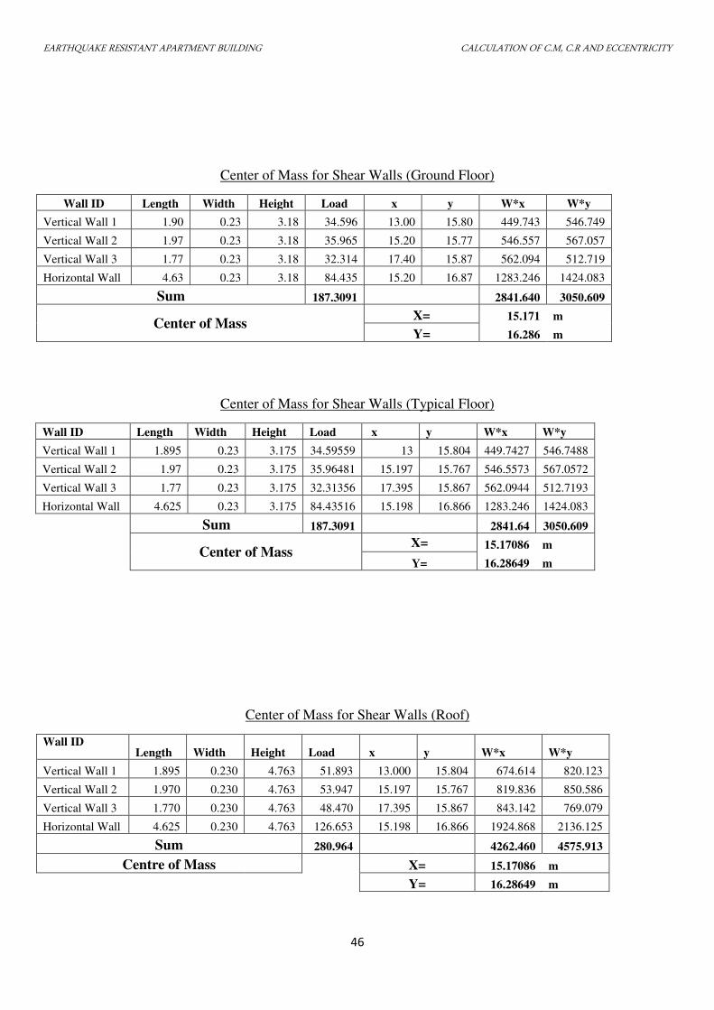
EARTHQUAKE RESISTANT APARTMENT BUILDING CALCULATION OF C.M, C.R AND ECCENTRICITY
46
Center of Mass for Shear Walls (Ground Floor)
Wall ID Length Width Height Load x y W*x W*y
Vertical Wall 1 1.90 0.23 3.18 34.596 13.00 15.80 449.743 546.749
Vertical Wall 2 1.97 0.23 3.18 35.965 15.20 15.77 546.557 567.057
Vertical Wall 3 1.77 0.23 3.18 32.314 17.40 15.87 562.094 512.719
Horizontal Wall 4.63 0.23 3.18 84.435 15.20 16.87 1283.246 1424.083
Sum 187.3091 2841.640 3050.609
Center of Mass X= 15.171 m
Y= 16.286 m
Center of Mass for Shear Walls (Typical Floor)
Wall ID Length Width Height Load x y W*x W*y
Vertical Wall 1 1.895 0.23 3.175 34.59559 13 15.804 449.7427 546.7488
Vertical Wall 2 1.97 0.23 3.175 35.96481 15.197 15.767 546.5573 567.0572
Vertical Wall 3 1.77 0.23 3.175 32.31356 17.395 15.867 562.0944 512.7193
Horizontal Wall 4.625 0.23 3.175 84.43516 15.198 16.866 1283.246 1424.083
Sum 187.3091 2841.64 3050.609
Center of Mass X= 15.17086 m
Y= 16.28649 m
Center of Mass for Shear Walls (Roof)
Wall ID Length Width Height Load x y W*x W*y
Vertical Wall 1 1.895 0.230 4.763 51.893 13.000 15.804 674.614 820.123
Vertical Wall 2 1.970 0.230 4.763 53.947 15.197 15.767 819.836 850.586
Vertical Wall 3 1.770 0.230 4.763 48.470 17.395 15.867 843.142 769.079
Horizontal Wall 4.625 0.230 4.763 126.653 15.198 16.866 1924.868 2136.125
Sum 280.964 4262.460 4575.913
Centre of Mass X= 15.17086 m
Y= 16.28649 m
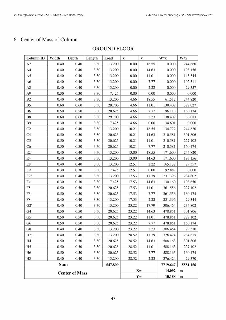
EARTHQUAKE RESISTANT APARTMENT BUILDING CALCULATION OF C.M, C.R AND ECCENTRICITY
47
6 Center of Mass of Column
GROUND FLOOR
Column ID Width Depth Length Load x y W*x W*y
A2 0.40 0.40 3.30 13.200 0.00 18.55 0.000 244.860
A4 0.40 0.40 3.30 13.200 0.00 14.63 0.000 193.156
A5 0.40 0.40 3.30 13.200 0.00 11.01 0.000 145.345
A6 0.40 0.40 3.30 13.200 0.00 7.77 0.000 102.511
A8 0.40 0.40 3.30 13.200 0.00 2.22 0.000 29.357
A9 0.30 0.30 3.30 7.425 0.00 0.00 0.000 0.000
B2 0.40 0.40 3.30 13.200 4.66 18.55 61.512 244.820
B5 0.60 0.60 3.30 29.700 4.66 11.01 138.402 327.027
B6 0.50 0.50 3.30 20.625 4.66 7.77 96.113 160.174
B8 0.60 0.60 3.30 29.700 4.66 2.23 138.402 66.083
B9 0.30 0.30 3.30 7.425 4.66 0.00 34.601 0.000
C2 0.40 0.40 3.30 13.200 10.21 18.55 134.772 244.820
C4 0.50 0.50 3.30 20.625 10.21 14.63 210.581 301.806
C5 0.50 0.50 3.30 20.625 10.21 11.01 210.581 227.102
C6 0.50 0.50 3.30 20.625 10.21 7.77 210.581 160.174
E2 0.40 0.40 3.30 13.200 13.00 18.55 171.600 244.820
E4 0.40 0.40 3.30 13.200 13.00 14.63 171.600 193.156
E8 0.40 0.40 3.30 13.200 12.51 2.22 165.132 29.357
E9 0.30 0.30 3.30 7.425 12.51 0.00 92.887 0.000
F2'' 0.40 0.40 3.30 13.200 17.53 17.79 231.396 234.802
F4 0.30 0.30 3.30 7.425 17.53 14.63 130.160 108.650
F5 0.50 0.50 3.30 20.625 17.53 11.01 361.556 227.102
F6 0.50 0.50 3.30 20.625 17.53 7.77 361.556 160.174
F8 0.40 0.40 3.30 13.200 17.53 2.22 231.396 29.344
G2'' 0.40 0.40 3.30 13.200 23.22 17.79 306.464 234.802
G4 0.50 0.50 3.30 20.625 23.22 14.63 478.851 301.806
G5 0.50 0.50 3.30 20.625 23.22 11.01 478.851 227.102
G6 0.50 0.50 3.30 20.625 23.22 7.77 478.851 160.174
G8 0.40 0.40 3.30 13.200 23.22 2.23 306.464 29.370
H2'' 0.40 0.40 3.30 13.200 28.52 17.79 376.424 234.815
H4 0.50 0.50 3.30 20.625 28.52 14.63 588.163 301.806
H5 0.50 0.50 3.30 20.625 28.52 11.01 588.163 227.102
H6 0.50 0.50 3.30 20.625 28.52 7.77 588.163 160.174
H8 0.40 0.40 3.30 13.200 28.52 2.23 376.424 29.370
Sum 547.800 7719.647 5581.156
Center of Mass X= 14.092 m
Y= 10.188 m
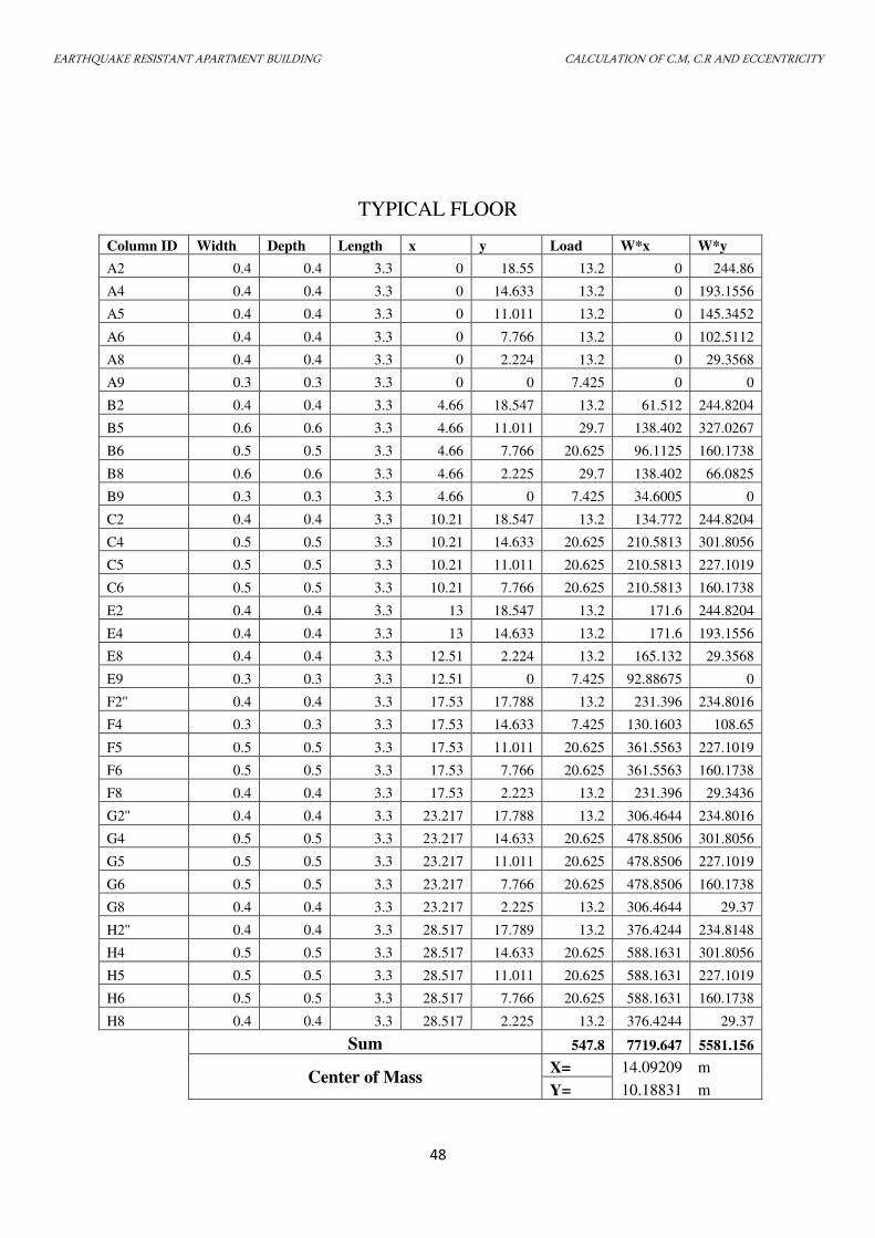
EARTHQUAKE RESISTANT APARTMENT BUILDING CALCULATION OF C.M, C.R AND ECCENTRICITY
48
TYPICAL FLOOR
Column ID Width Depth Length x y Load W*x W*y
A2 0.4 0.4 3.3 0 18.55 13.2 0 244.86
A4 0.4 0.4 3.3 0 14.633 13.2 0 193.1556
A5 0.4 0.4 3.3 0 11.011 13.2 0 145.3452
A6 0.4 0.4 3.3 0 7.766 13.2 0 102.5112
A8 0.4 0.4 3.3 0 2.224 13.2 0 29.3568
A9 0.3 0.3 3.3 0 0 7.425 0 0
B2 0.4 0.4 3.3 4.66 18.547 13.2 61.512 244.8204
B5 0.6 0.6 3.3 4.66 11.011 29.7 138.402 327.0267
B6 0.5 0.5 3.3 4.66 7.766 20.625 96.1125 160.1738
B8 0.6 0.6 3.3 4.66 2.225 29.7 138.402 66.0825
B9 0.3 0.3 3.3 4.66 0 7.425 34.6005 0
C2 0.4 0.4 3.3 10.21 18.547 13.2 134.772 244.8204
C4 0.5 0.5 3.3 10.21 14.633 20.625 210.5813 301.8056
C5 0.5 0.5 3.3 10.21 11.011 20.625 210.5813 227.1019
C6 0.5 0.5 3.3 10.21 7.766 20.625 210.5813 160.1738
E2 0.4 0.4 3.3 13 18.547 13.2 171.6 244.8204
E4 0.4 0.4 3.3 13 14.633 13.2 171.6 193.1556
E8 0.4 0.4 3.3 12.51 2.224 13.2 165.132 29.3568
E9 0.3 0.3 3.3 12.51 0 7.425 92.88675 0
F2'' 0.4 0.4 3.3 17.53 17.788 13.2 231.396 234.8016
F4 0.3 0.3 3.3 17.53 14.633 7.425 130.1603 108.65
F5 0.5 0.5 3.3 17.53 11.011 20.625 361.5563 227.1019
F6 0.5 0.5 3.3 17.53 7.766 20.625 361.5563 160.1738
F8 0.4 0.4 3.3 17.53 2.223 13.2 231.396 29.3436
G2'' 0.4 0.4 3.3 23.217 17.788 13.2 306.4644 234.8016
G4 0.5 0.5 3.3 23.217 14.633 20.625 478.8506 301.8056
G5 0.5 0.5 3.3 23.217 11.011 20.625 478.8506 227.1019
G6 0.5 0.5 3.3 23.217 7.766 20.625 478.8506 160.1738
G8 0.4 0.4 3.3 23.217 2.225 13.2 306.4644 29.37
H2'' 0.4 0.4 3.3 28.517 17.789 13.2 376.4244 234.8148
H4 0.5 0.5 3.3 28.517 14.633 20.625 588.1631 301.8056
H5 0.5 0.5 3.3 28.517 11.011 20.625 588.1631 227.1019
H6 0.5 0.5 3.3 28.517 7.766 20.625 588.1631 160.1738
H8 0.4 0.4 3.3 28.517 2.225 13.2 376.4244 29.37
Sum 547.8 7719.647 5581.156
Center of Mass X= 14.09209 m
Y= 10.18831 m
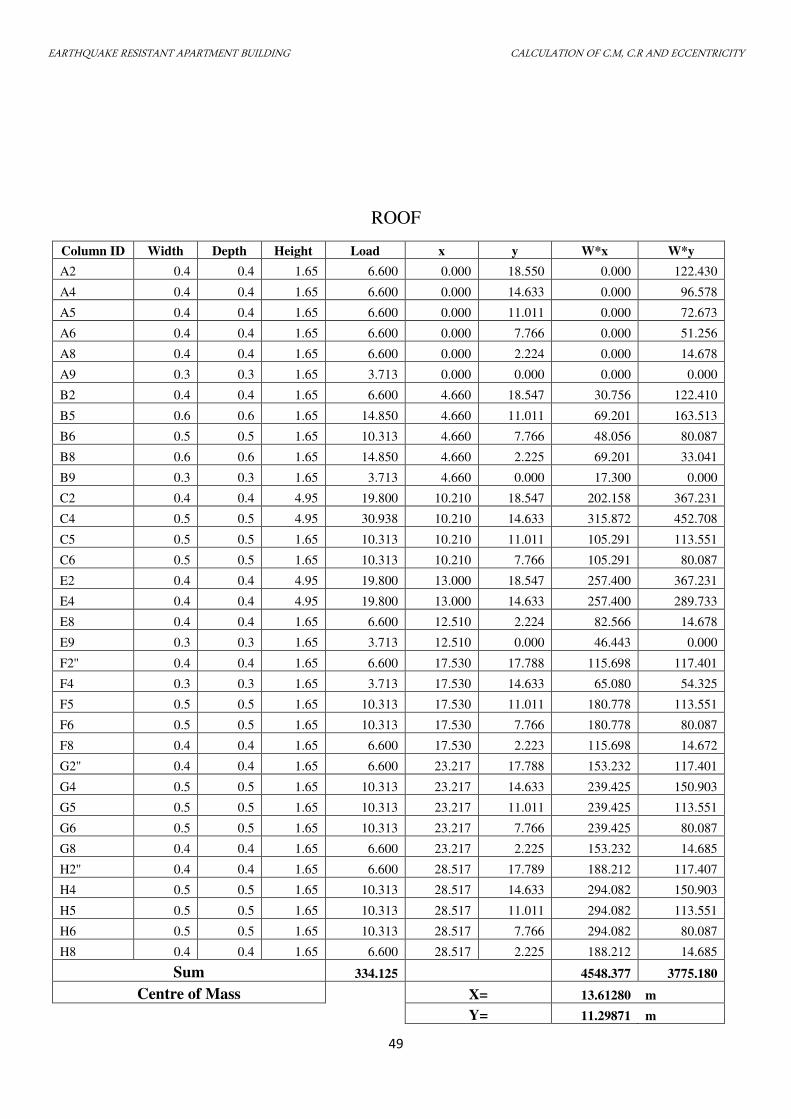
EARTHQUAKE RESISTANT APARTMENT BUILDING CALCULATION OF C.M, C.R AND ECCENTRICITY
49
ROOF
Column ID Width Depth Height Load x y W*x W*y
A2 0.4 0.4 1.65 6.600 0.000 18.550 0.000 122.430
A4 0.4 0.4 1.65 6.600 0.000 14.633 0.000 96.578
A5 0.4 0.4 1.65 6.600 0.000 11.011 0.000 72.673
A6 0.4 0.4 1.65 6.600 0.000 7.766 0.000 51.256
A8 0.4 0.4 1.65 6.600 0.000 2.224 0.000 14.678
A9 0.3 0.3 1.65 3.713 0.000 0.000 0.000 0.000
B2 0.4 0.4 1.65 6.600 4.660 18.547 30.756 122.410
B5 0.6 0.6 1.65 14.850 4.660 11.011 69.201 163.513
B6 0.5 0.5 1.65 10.313 4.660 7.766 48.056 80.087
B8 0.6 0.6 1.65 14.850 4.660 2.225 69.201 33.041
B9 0.3 0.3 1.65 3.713 4.660 0.000 17.300 0.000
C2 0.4 0.4 4.95 19.800 10.210 18.547 202.158 367.231
C4 0.5 0.5 4.95 30.938 10.210 14.633 315.872 452.708
C5 0.5 0.5 1.65 10.313 10.210 11.011 105.291 113.551
C6 0.5 0.5 1.65 10.313 10.210 7.766 105.291 80.087
E2 0.4 0.4 4.95 19.800 13.000 18.547 257.400 367.231
E4 0.4 0.4 4.95 19.800 13.000 14.633 257.400 289.733
E8 0.4 0.4 1.65 6.600 12.510 2.224 82.566 14.678
E9 0.3 0.3 1.65 3.713 12.510 0.000 46.443 0.000
F2'' 0.4 0.4 1.65 6.600 17.530 17.788 115.698 117.401
F4 0.3 0.3 1.65 3.713 17.530 14.633 65.080 54.325
F5 0.5 0.5 1.65 10.313 17.530 11.011 180.778 113.551
F6 0.5 0.5 1.65 10.313 17.530 7.766 180.778 80.087
F8 0.4 0.4 1.65 6.600 17.530 2.223 115.698 14.672
G2'' 0.4 0.4 1.65 6.600 23.217 17.788 153.232 117.401
G4 0.5 0.5 1.65 10.313 23.217 14.633 239.425 150.903
G5 0.5 0.5 1.65 10.313 23.217 11.011 239.425 113.551
G6 0.5 0.5 1.65 10.313 23.217 7.766 239.425 80.087
G8 0.4 0.4 1.65 6.600 23.217 2.225 153.232 14.685
H2'' 0.4 0.4 1.65 6.600 28.517 17.789 188.212 117.407
H4 0.5 0.5 1.65 10.313 28.517 14.633 294.082 150.903
H5 0.5 0.5 1.65 10.313 28.517 11.011 294.082 113.551
H6 0.5 0.5 1.65 10.313 28.517 7.766 294.082 80.087
H8 0.4 0.4 1.65 6.600 28.517 2.225 188.212 14.685
Sum 334.125 4548.377 3775.180
Centre of Mass X= 13.61280 m
Y= 11.29871 m
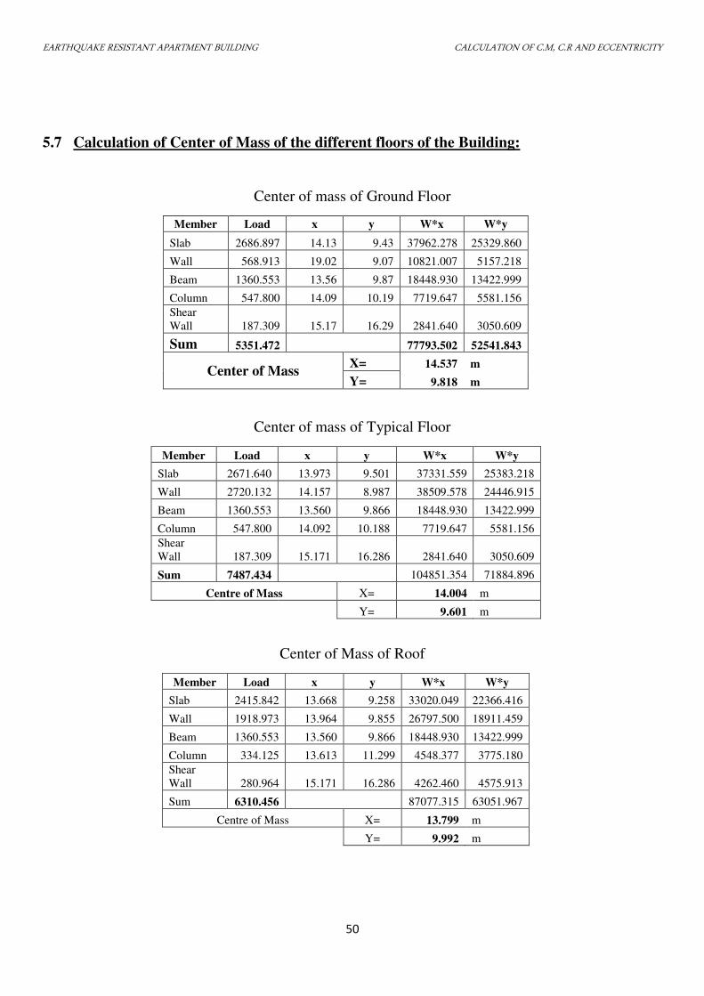
EARTHQUAKE RESISTANT APARTMENT BUILDING CALCULATION OF C.M, C.R AND ECCENTRICITY
50
5.7 Calculation of Center of Mass of the different floors of the Building:
Center of mass of Ground Floor
Member Load x y W*x W*y
Slab 2686.897 14.13 9.43 37962.278 25329.860
Wall 568.913 19.02 9.07 10821.007 5157.218
Beam 1360.553 13.56 9.87 18448.930 13422.999
Column 547.800 14.09 10.19 7719.647 5581.156
Shear
Wall 187.309 15.17 16.29 2841.640 3050.609
Sum 5351.472 77793.502 52541.843
Center of Mass X= 14.537 m
Y= 9.818 m
Center of mass of Typical Floor
Member Load x y W*x W*y
Slab 2671.640 13.973 9.501 37331.559 25383.218
Wall 2720.132 14.157 8.987 38509.578 24446.915
Beam 1360.553 13.560 9.866 18448.930 13422.999
Column 547.800 14.092 10.188 7719.647 5581.156
Shear
Wall 187.309 15.171 16.286 2841.640 3050.609
Sum 7487.434 104851.354 71884.896
Centre of Mass X= 14.004 m
Y= 9.601 m
Center of Mass of Roof
Member Load x y W*x W*y
Slab 2415.842 13.668 9.258 33020.049 22366.416
Wall 1918.973 13.964 9.855 26797.500 18911.459
Beam 1360.553 13.560 9.866 18448.930 13422.999
Column 334.125 13.613 11.299 4548.377 3775.180
Shear
Wall 280.964 15.171 16.286 4262.460 4575.913
Sum 6310.456 87077.315 63051.967
Centre of Mass X= 13.799 m
Y= 9.992 m
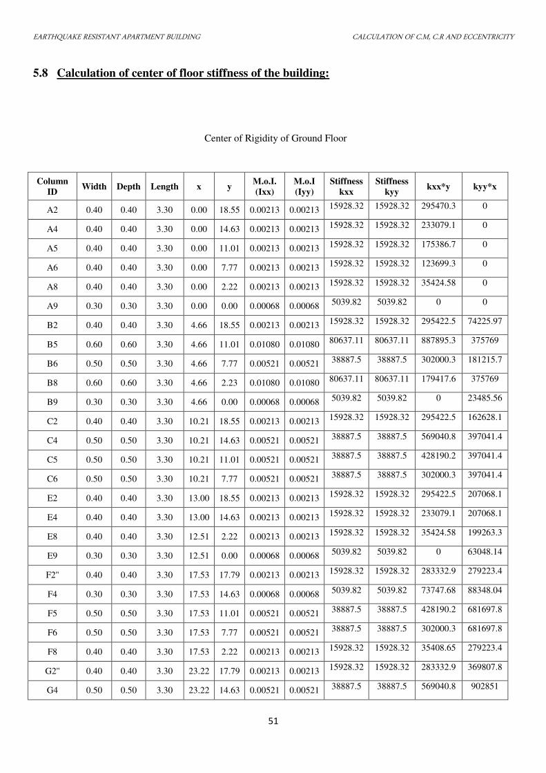
EARTHQUAKE RESISTANT APARTMENT BUILDING CALCULATION OF C.M, C.R AND ECCENTRICITY
51
5.8 Calculation of center of floor stiffness of the building:
Center of Rigidity of Ground Floor
Column
ID Width Depth Length x y
M.o.I.
(Ixx)
M.o.I
(Iyy)
Stiffness
kxx
Stiffness
kyy kxx*y kyy*x
A2 0.40 0.40 3.30 0.00 18.55 0.00213 0.00213 15928.32 15928.32 295470.3 0
A4 0.40 0.40 3.30 0.00 14.63 0.00213 0.00213 15928.32 15928.32 233079.1 0
A5 0.40 0.40 3.30 0.00 11.01 0.00213 0.00213 15928.32 15928.32 175386.7 0
A6 0.40 0.40 3.30 0.00 7.77 0.00213 0.00213 15928.32 15928.32 123699.3 0
A8 0.40 0.40 3.30 0.00 2.22 0.00213 0.00213 15928.32 15928.32 35424.58 0
A9 0.30 0.30 3.30 0.00 0.00 0.00068 0.00068 5039.82 5039.82 0 0
B2 0.40 0.40 3.30 4.66 18.55 0.00213 0.00213 15928.32 15928.32 295422.5 74225.97
B5 0.60 0.60 3.30 4.66 11.01 0.01080 0.01080 80637.11 80637.11 887895.3 375769
B6 0.50 0.50 3.30 4.66 7.77 0.00521 0.00521 38887.5 38887.5 302000.3 181215.7
B8 0.60 0.60 3.30 4.66 2.23 0.01080 0.01080 80637.11 80637.11 179417.6 375769
B9 0.30 0.30 3.30 4.66 0.00 0.00068 0.00068 5039.82 5039.82 0 23485.56
C2 0.40 0.40 3.30 10.21 18.55 0.00213 0.00213 15928.32 15928.32 295422.5 162628.1
C4 0.50 0.50 3.30 10.21 14.63 0.00521 0.00521 38887.5 38887.5 569040.8 397041.4
C5 0.50 0.50 3.30 10.21 11.01 0.00521 0.00521 38887.5 38887.5 428190.2 397041.4
C6 0.50 0.50 3.30 10.21 7.77 0.00521 0.00521 38887.5 38887.5 302000.3 397041.4
E2 0.40 0.40 3.30 13.00 18.55 0.00213 0.00213 15928.32 15928.32 295422.5 207068.1
E4 0.40 0.40 3.30 13.00 14.63 0.00213 0.00213 15928.32 15928.32 233079.1 207068.1
E8 0.40 0.40 3.30 12.51 2.22 0.00213 0.00213 15928.32 15928.32 35424.58 199263.3
E9 0.30 0.30 3.30 12.51 0.00 0.00068 0.00068 5039.82 5039.82 0 63048.14
F2'' 0.40 0.40 3.30 17.53 17.79 0.00213 0.00213 15928.32 15928.32 283332.9 279223.4
F4 0.30 0.30 3.30 17.53 14.63 0.00068 0.00068 5039.82 5039.82 73747.68 88348.04
F5 0.50 0.50 3.30 17.53 11.01 0.00521 0.00521 38887.5 38887.5 428190.2 681697.8
F6 0.50 0.50 3.30 17.53 7.77 0.00521 0.00521 38887.5 38887.5 302000.3 681697.8
F8 0.40 0.40 3.30 17.53 2.22 0.00213 0.00213 15928.32 15928.32 35408.65 279223.4
G2'' 0.40 0.40 3.30 23.22 17.79 0.00213 0.00213 15928.32 15928.32 283332.9 369807.8
G4 0.50 0.50 3.30 23.22 14.63 0.00521 0.00521 38887.5 38887.5 569040.8 902851
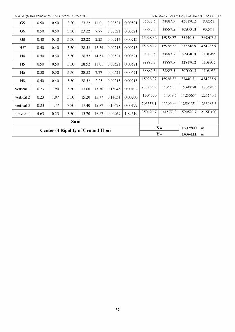
EARTHQUAKE RESISTANT APARTMENT BUILDING CALCULATION OF C.M, C.R AND ECCENTRICITY
52
G5 0.50 0.50 3.30 23.22 11.01 0.00521 0.00521 38887.5 38887.5 428190.2 902851
G6 0.50 0.50 3.30 23.22 7.77 0.00521 0.00521 38887.5 38887.5 302000.3 902851
G8 0.40 0.40 3.30 23.22 2.23 0.00213 0.00213 15928.32 15928.32 35440.51 369807.8
H2'' 0.40 0.40 3.30 28.52 17.79 0.00213 0.00213 15928.32 15928.32 283348.9 454227.9
H4 0.50 0.50 3.30 28.52 14.63 0.00521 0.00521 38887.5 38887.5 569040.8 1108955
H5 0.50 0.50 3.30 28.52 11.01 0.00521 0.00521 38887.5 38887.5 428190.2 1108955
H6 0.50 0.50 3.30 28.52 7.77 0.00521 0.00521 38887.5 38887.5 302000.3 1108955
H8 0.40 0.40 3.30 28.52 2.23 0.00213 0.00213 15928.32 15928.32 35440.51 454227.9
vertical 1 0.23 1.90 3.30 13.00 15.80 0.13043 0.00192 973835.2 14345.73 15390491 186494.5
vertical 2 0.23 1.97 3.30 15.20 15.77 0.14654 0.00200 1094099 14913.5 17250654 226640.5
vertical 3 0.23 1.77 3.30 17.40 15.87 0.10628 0.00179 793556.1 13399.44 12591354 233083.3
horizontal 4.63 0.23 3.30 15.20 16.87 0.00469 1.89619 35012.67 14157710 590523.7 2.15E+08
Sum
Center of Rigidity of Ground Floor X= 15.19800 m
Y= 14.44111 m
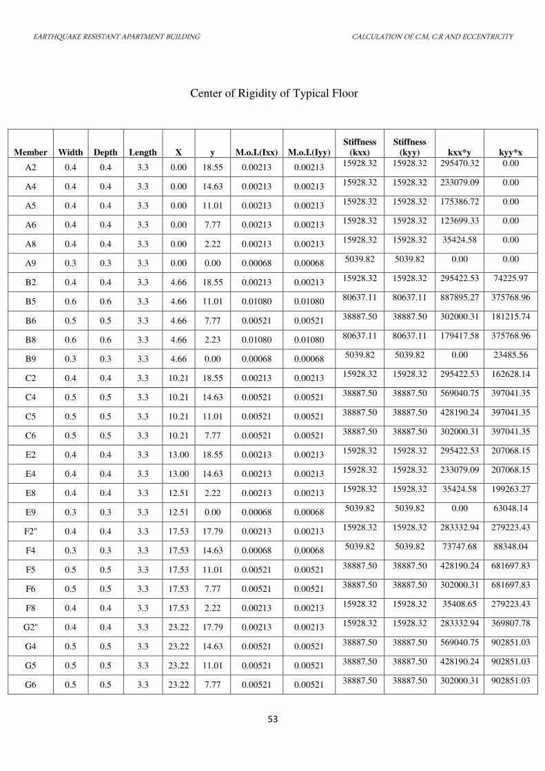
EARTHQUAKE RESISTANT APARTMENT BUILDING CALCULATION OF C.M, C.R AND ECCENTRICITY
53
Center of Rigidity of Typical Floor
Member Width Depth Length X y M.o.I.(Ixx) M.o.I.(Iyy)
Stiffness
(kxx)
Stiffness
(kyy) kxx*y kyy*x
A2 0.4 0.4 3.3 0.00 18.55 0.00213 0.00213 15928.32 15928.32 295470.32 0.00
A4 0.4 0.4 3.3 0.00 14.63 0.00213 0.00213 15928.32 15928.32 233079.09 0.00
A5 0.4 0.4 3.3 0.00 11.01 0.00213 0.00213 15928.32 15928.32 175386.72 0.00
A6 0.4 0.4 3.3 0.00 7.77 0.00213 0.00213 15928.32 15928.32 123699.33 0.00
A8 0.4 0.4 3.3 0.00 2.22 0.00213 0.00213 15928.32 15928.32 35424.58 0.00
A9 0.3 0.3 3.3 0.00 0.00 0.00068 0.00068 5039.82 5039.82 0.00 0.00
B2 0.4 0.4 3.3 4.66 18.55 0.00213 0.00213 15928.32 15928.32 295422.53 74225.97
B5 0.6 0.6 3.3 4.66 11.01 0.01080 0.01080 80637.11 80637.11 887895.27 375768.96
B6 0.5 0.5 3.3 4.66 7.77 0.00521 0.00521 38887.50 38887.50 302000.31 181215.74
B8 0.6 0.6 3.3 4.66 2.23 0.01080 0.01080 80637.11 80637.11 179417.58 375768.96
B9 0.3 0.3 3.3 4.66 0.00 0.00068 0.00068 5039.82 5039.82 0.00 23485.56
C2 0.4 0.4 3.3 10.21 18.55 0.00213 0.00213 15928.32 15928.32 295422.53 162628.14
C4 0.5 0.5 3.3 10.21 14.63 0.00521 0.00521 38887.50 38887.50 569040.75 397041.35
C5 0.5 0.5 3.3 10.21 11.01 0.00521 0.00521 38887.50 38887.50 428190.24 397041.35
C6 0.5 0.5 3.3 10.21 7.77 0.00521 0.00521 38887.50 38887.50 302000.31 397041.35
E2 0.4 0.4 3.3 13.00 18.55 0.00213 0.00213 15928.32 15928.32 295422.53 207068.15
E4 0.4 0.4 3.3 13.00 14.63 0.00213 0.00213 15928.32 15928.32 233079.09 207068.15
E8 0.4 0.4 3.3 12.51 2.22 0.00213 0.00213 15928.32 15928.32 35424.58 199263.27
E9 0.3 0.3 3.3 12.51 0.00 0.00068 0.00068 5039.82 5039.82 0.00 63048.14
F2'' 0.4 0.4 3.3 17.53 17.79 0.00213 0.00213 15928.32 15928.32 283332.94 279223.43
F4 0.3 0.3 3.3 17.53 14.63 0.00068 0.00068 5039.82 5039.82 73747.68 88348.04
F5 0.5 0.5 3.3 17.53 11.01 0.00521 0.00521 38887.50 38887.50 428190.24 681697.83
F6 0.5 0.5 3.3 17.53 7.77 0.00521 0.00521 38887.50 38887.50 302000.31 681697.83
F8 0.4 0.4 3.3 17.53 2.22 0.00213 0.00213 15928.32 15928.32 35408.65 279223.43
G2'' 0.4 0.4 3.3 23.22 17.79 0.00213 0.00213 15928.32 15928.32 283332.94 369807.78
G4 0.5 0.5 3.3 23.22 14.63 0.00521 0.00521 38887.50 38887.50 569040.75 902851.03
G5 0.5 0.5 3.3 23.22 11.01 0.00521 0.00521 38887.50 38887.50 428190.24 902851.03
G6 0.5 0.5 3.3 23.22 7.77 0.00521 0.00521 38887.50 38887.50 302000.31 902851.03
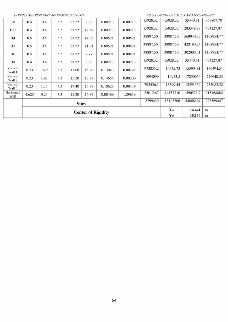
EARTHQUAKE RESISTANT APARTMENT BUILDING CALCULATION OF C.M, C.R AND ECCENTRICITY
54
G8 0.4 0.4 3.3 23.22 2.23 0.00213 0.00213 15928.32 15928.32 35440.51 369807.78
H2'' 0.4 0.4 3.3 28.52 17.79 0.00213 0.00213 15928.32 15928.32 283348.87 454227.87
H4 0.5 0.5 3.3 28.52 14.63 0.00521 0.00521 38887.50 38887.50 569040.75 1108954.77
H5 0.5 0.5 3.3 28.52 11.01 0.00521 0.00521 38887.50 38887.50 428190.24 1108954.77
H6 0.5 0.5 3.3 28.52 7.77 0.00521 0.00521 38887.50 38887.50 302000.31 1108954.77
H8 0.4 0.4 3.3 28.52 2.23 0.00213 0.00213 15928.32 15928.32 35440.51 454227.87
Vertical
Wall 1 0.23 1.895 3.3 13.00 15.80 0.13043 0.00192 973835.2 14345.73 15390491 186494.51
Vertical
Wall 2 0.23 1.97 3.3 15.20 15.77 0.14654 0.00200 1094099 14913.5 17250654 226640.53
Vertical
Wall 3 0.23 1.77 3.3 17.40 15.87 0.10628 0.00179 793556.1 13399.44 12591354 233083.32
Horizontal
Wall 4.625 0.23 3.3 15.20 16.87 0.00469 1.89619 35012.67 14157710 590523.7 215168884
Sum 3799439 15103306 54868104 228569447
Center of Rigidity X= 14.441 m
Y= 15.134 m
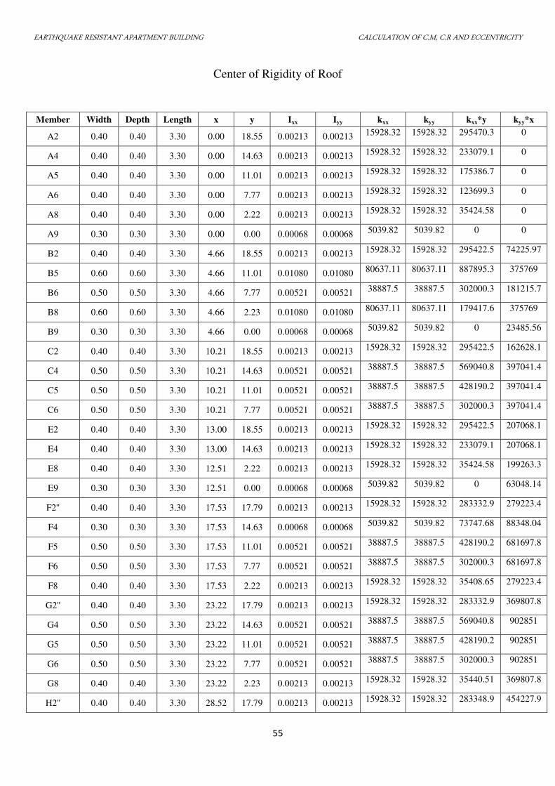
EARTHQUAKE RESISTANT APARTMENT BUILDING CALCULATION OF C.M, C.R AND ECCENTRICITY
55
Center of Rigidity of Roof
Member Width Depth Length x y Ixx Iyy kxx kyy kxx*y kyy*x
A2 0.40 0.40 3.30 0.00 18.55 0.00213 0.00213 15928.32 15928.32 295470.3 0
A4 0.40 0.40 3.30 0.00 14.63 0.00213 0.00213 15928.32 15928.32 233079.1 0
A5 0.40 0.40 3.30 0.00 11.01 0.00213 0.00213 15928.32 15928.32 175386.7 0
A6 0.40 0.40 3.30 0.00 7.77 0.00213 0.00213 15928.32 15928.32 123699.3 0
A8 0.40 0.40 3.30 0.00 2.22 0.00213 0.00213 15928.32 15928.32 35424.58 0
A9 0.30 0.30 3.30 0.00 0.00 0.00068 0.00068 5039.82 5039.82 0 0
B2 0.40 0.40 3.30 4.66 18.55 0.00213 0.00213 15928.32 15928.32 295422.5 74225.97
B5 0.60 0.60 3.30 4.66 11.01 0.01080 0.01080 80637.11 80637.11 887895.3 375769
B6 0.50 0.50 3.30 4.66 7.77 0.00521 0.00521 38887.5 38887.5 302000.3 181215.7
B8 0.60 0.60 3.30 4.66 2.23 0.01080 0.01080 80637.11 80637.11 179417.6 375769
B9 0.30 0.30 3.30 4.66 0.00 0.00068 0.00068 5039.82 5039.82 0 23485.56
C2 0.40 0.40 3.30 10.21 18.55 0.00213 0.00213 15928.32 15928.32 295422.5 162628.1
C4 0.50 0.50 3.30 10.21 14.63 0.00521 0.00521 38887.5 38887.5 569040.8 397041.4
C5 0.50 0.50 3.30 10.21 11.01 0.00521 0.00521 38887.5 38887.5 428190.2 397041.4
C6 0.50 0.50 3.30 10.21 7.77 0.00521 0.00521 38887.5 38887.5 302000.3 397041.4
E2 0.40 0.40 3.30 13.00 18.55 0.00213 0.00213 15928.32 15928.32 295422.5 207068.1
E4 0.40 0.40 3.30 13.00 14.63 0.00213 0.00213 15928.32 15928.32 233079.1 207068.1
E8 0.40 0.40 3.30 12.51 2.22 0.00213 0.00213 15928.32 15928.32 35424.58 199263.3
E9 0.30 0.30 3.30 12.51 0.00 0.00068 0.00068 5039.82 5039.82 0 63048.14
F2'' 0.40 0.40 3.30 17.53 17.79 0.00213 0.00213 15928.32 15928.32 283332.9 279223.4
F4 0.30 0.30 3.30 17.53 14.63 0.00068 0.00068 5039.82 5039.82 73747.68 88348.04
F5 0.50 0.50 3.30 17.53 11.01 0.00521 0.00521 38887.5 38887.5 428190.2 681697.8
F6 0.50 0.50 3.30 17.53 7.77 0.00521 0.00521 38887.5 38887.5 302000.3 681697.8
F8 0.40 0.40 3.30 17.53 2.22 0.00213 0.00213 15928.32 15928.32 35408.65 279223.4
G2'' 0.40 0.40 3.30 23.22 17.79 0.00213 0.00213 15928.32 15928.32 283332.9 369807.8
G4 0.50 0.50 3.30 23.22 14.63 0.00521 0.00521 38887.5 38887.5 569040.8 902851
G5 0.50 0.50 3.30 23.22 11.01 0.00521 0.00521 38887.5 38887.5 428190.2 902851
G6 0.50 0.50 3.30 23.22 7.77 0.00521 0.00521 38887.5 38887.5 302000.3 902851
G8 0.40 0.40 3.30 23.22 2.23 0.00213 0.00213 15928.32 15928.32 35440.51 369807.8
H2'' 0.40 0.40 3.30 28.52 17.79 0.00213 0.00213 15928.32 15928.32 283348.9 454227.9
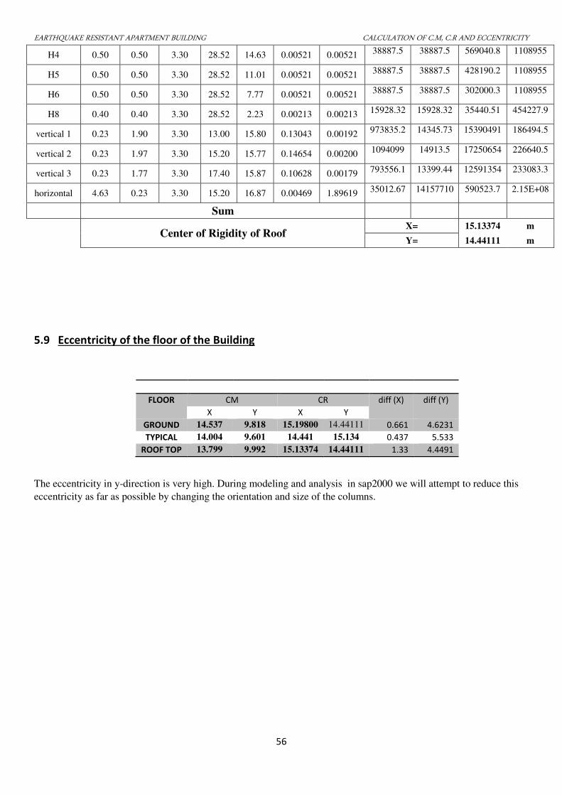
EARTHQUAKE RESISTANT APARTMENT BUILDING CALCULATION OF C.M, C.R AND ECCENTRICITY
56
H4 0.50 0.50 3.30 28.52 14.63 0.00521 0.00521 38887.5 38887.5 569040.8 1108955
H5 0.50 0.50 3.30 28.52 11.01 0.00521 0.00521 38887.5 38887.5 428190.2 1108955
H6 0.50 0.50 3.30 28.52 7.77 0.00521 0.00521 38887.5 38887.5 302000.3 1108955
H8 0.40 0.40 3.30 28.52 2.23 0.00213 0.00213 15928.32 15928.32 35440.51 454227.9
vertical 1 0.23 1.90 3.30 13.00 15.80 0.13043 0.00192 973835.2 14345.73 15390491 186494.5
vertical 2 0.23 1.97 3.30 15.20 15.77 0.14654 0.00200 1094099 14913.5 17250654 226640.5
vertical 3 0.23 1.77 3.30 17.40 15.87 0.10628 0.00179 793556.1 13399.44 12591354 233083.3
horizontal 4.63 0.23 3.30 15.20 16.87 0.00469 1.89619 35012.67 14157710 590523.7 2.15E+08
Sum
Center of Rigidity of Roof X= 15.13374 m
Y= 14.44111 m
5.9 Eccentricity of the floor of the Building
FLOOR CM CR diff (X) diff (Y)
X Y X Y
GROUND 14.537 9.818 15.19800 14.44111 0.661 4.6231
TYPICAL 14.004 9.601 14.441 15.134 0.437 5.533
ROOF TOP 13.799 9.992 15.13374 14.44111 1.33 4.4491
The eccentricity in y-direction is very high. During modeling and analysis in sap2000 we will attempt to reduce this
eccentricity as far as possible by changing the orientation and size of the columns.
EARTHQUAKE RESISTANT APARTMENT BUILDING STRUCTURAL ANALYSIS
57
STRUCTURAL ANALYSIS
6.1 ANALYSIS OF BUILDING
Earthquake resistant design of a structure is done in order to provide the structure with the
appropriate dynamic and structural characteristics so that the structure would response to an
acceptable level without failure during an earthquake. The design is aimed at achieving the
acceptable probability of the structure of performing well during its intended life period.
Designed with appropriate degree of safety, the structure should withstand all the loads and
deformation from its normal construction and during its use. They should possess adequate
durability and resistance to misuse and fire.
For the purpose of seismic analysis, we used the structure analysis program SAP2000. In
SAP2000, we modeled the structure as rigid floor diaphragm system. A floor diaphragm is
modeled as a rigid horizontal plane parallel to global X-Y plane so that all points of any floor
diaphragm cannot displace to each other in X-Y plane.
In SAP2000, we have done 3D analysis. Earthquake load is calculated as per seismic
coefficient design using code IS 1893:2002. The program automatically calculates the dead load,
wall load is applied as uniformly distributed load and live load on slab is applied as uniformly
distributed load to frame. The seismic load is applied at the center of mass.
6.2 BEAM AND COLUMN MEMBERS
BEAMS
There are two types of beams used in the structure:
i. Main beam: Initially beams of size 600*300 were used but it was found to be inadequate so
the size of beam was increased to 700*400 mm.
ii. Secondary beam: secondary beams of size 420*210 were initially used but were later
increased to 500*250.
.
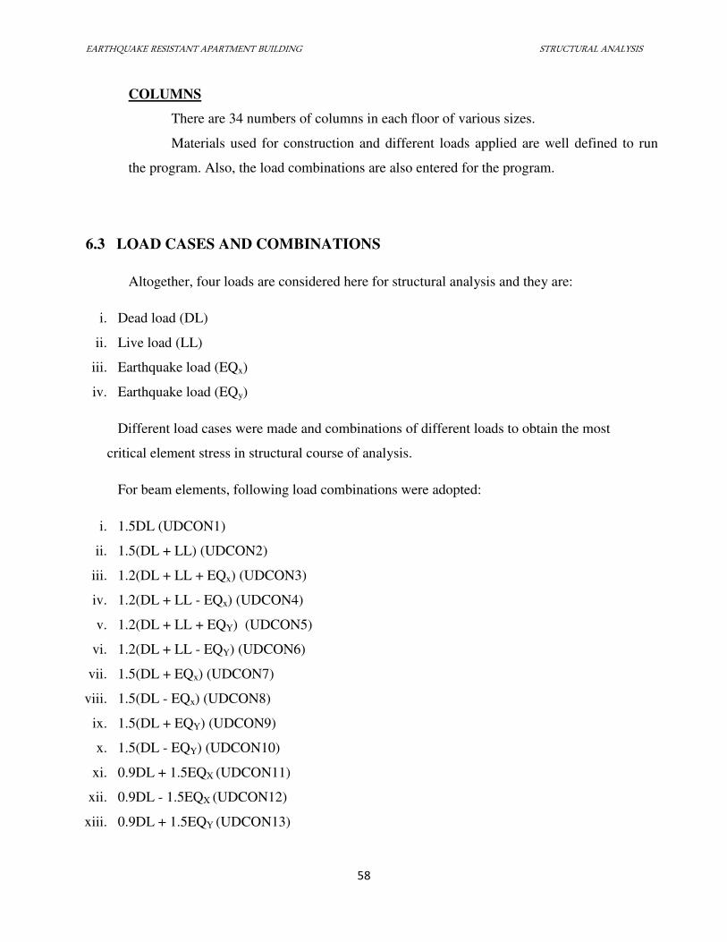
EARTHQUAKE RESISTANT APARTMENT BUILDING STRUCTURAL ANALYSIS
58
COLUMNS
There are 34 numbers of columns in each floor of various sizes.
Materials used for construction and different loads applied are well defined to run
the program. Also, the load combinations are also entered for the program.
6.3 LOAD CASES AND COMBINATIONS
Altogether, four loads are considered here for structural analysis and they are:
i. Dead load (DL)
ii. Live load (LL)
iii. Earthquake load (EQx)
iv. Earthquake load (EQy)
Different load cases were made and combinations of different loads to obtain the most
critical element stress in structural course of analysis.
For beam elements, following load combinations were adopted:
i. 1.5DL (UDCON1)
ii. 1.5(DL + LL) (UDCON2)
iii. 1.2(DL + LL + EQx) (UDCON3)
iv. 1.2(DL + LL - EQx) (UDCON4)
v. 1.2(DL + LL + EQY) (UDCON5)
vi. 1.2(DL + LL - EQY) (UDCON6)
vii. 1.5(DL + EQx) (UDCON7)
viii. 1.5(DL - EQx) (UDCON8)
ix. 1.5(DL + EQY) (UDCON9)
x. 1.5(DL - EQY) (UDCON10)
xi. 0.9DL + 1.5EQX (UDCON11)
xii. 0.9DL - 1.5EQX (UDCON12)
xiii. 0.9DL + 1.5EQY (UDCON13)
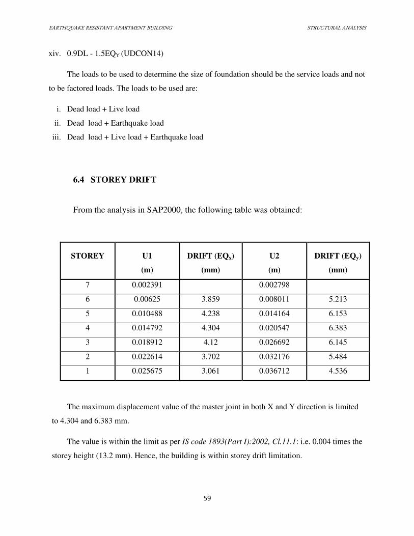
EARTHQUAKE RESISTANT APARTMENT BUILDING STRUCTURAL ANALYSIS
59
xiv. 0.9DL - 1.5EQY (UDCON14)
The loads to be used to determine the size of foundation should be the service loads and not
to be factored loads. The loads to be used are:
i. Dead load + Live load
ii. Dead load + Earthquake load
iii. Dead load + Live load + Earthquake load
6.4 STOREY DRIFT
From the analysis in SAP2000, the following table was obtained:
STOREY U1
(m)
DRIFT (EQx)
(mm)
U2
(m)
DRIFT (EQy)
(mm)
7 0.002391 0.002798
6 0.00625 3.859 0.008011 5.213
5 0.010488 4.238 0.014164 6.153
4 0.014792 4.304 0.020547 6.383
3 0.018912 4.12 0.026692 6.145
2 0.022614 3.702 0.032176 5.484
1 0.025675 3.061 0.036712 4.536
The maximum displacement value of the master joint in both X and Y direction is limited
to 4.304 and 6.383 mm.
The value is within the limit as per IS code 1893(Part I):2002, Cl.11.1: i.e. 0.004 times the
storey height (13.2 mm). Hence, the building is within storey drift limitation.
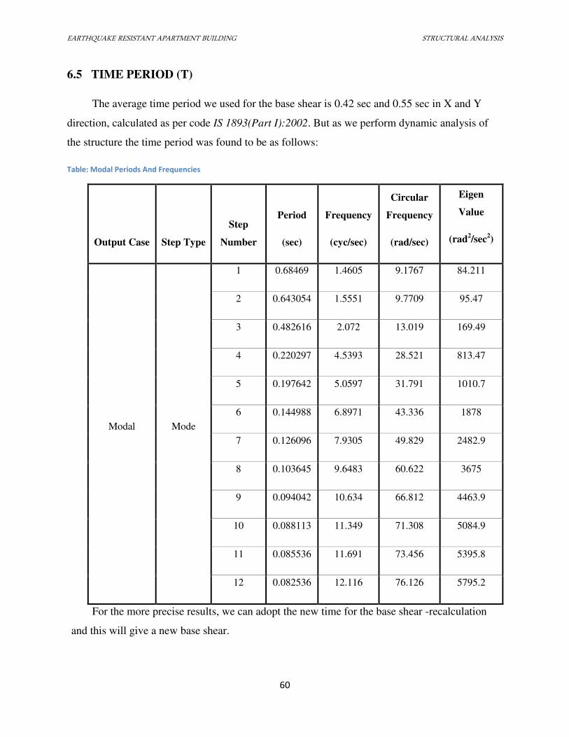
EARTHQUAKE RESISTANT APARTMENT BUILDING STRUCTURAL ANALYSIS
60
6.5 TIME PERIOD (T)
The average time period we used for the base shear is 0.42 sec and 0.55 sec in X and Y
direction, calculated as per code IS 1893(Part I):2002. But as we perform dynamic analysis of
the structure the time period was found to be as follows:
Table: Modal Periods And Frequencies
Output Case Step Type
Step
Number
Period
(sec)
Frequency
(cyc/sec)
Circular
Frequency
(rad/sec)
Eigen
Value
(rad2/sec
2)
Modal Mode
1 0.68469 1.4605 9.1767 84.211
2 0.643054 1.5551 9.7709 95.47
3 0.482616 2.072 13.019 169.49
4 0.220297 4.5393 28.521 813.47
5 0.197642 5.0597 31.791 1010.7
6 0.144988 6.8971 43.336 1878
7 0.126096 7.9305 49.829 2482.9
8 0.103645 9.6483 60.622 3675
9 0.094042 10.634 66.812 4463.9
10 0.088113 11.349 71.308 5084.9
11 0.085536 11.691 73.456 5395.8
12 0.082536 12.116 76.126 5795.2
For the more precise results, we can adopt the new time for the base shear -recalculation
and this will give a new base shear.
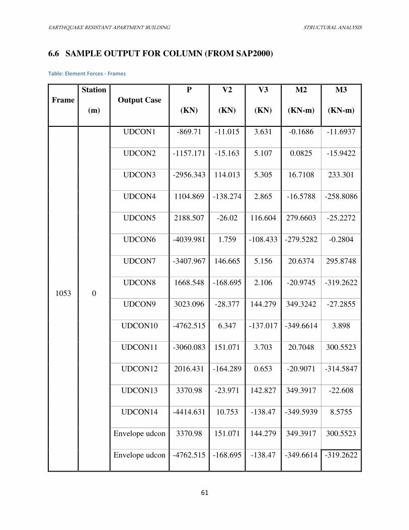
EARTHQUAKE RESISTANT APARTMENT BUILDING STRUCTURAL ANALYSIS
61
6.6 SAMPLE OUTPUT FOR COLUMN (FROM SAP2000)
Table: Element Forces - Frames
Frame
Station
(m)
Output Case
P
(KN)
V2
(KN)
V3
(KN)
M2
(KN-m)
M3
(KN-m)
1053 0
UDCON1 -869.71 -11.015 3.631 -0.1686 -11.6937
UDCON2 -1157.171 -15.163 5.107 0.0825 -15.9422
UDCON3 -2956.343 114.013 5.305 16.7108 233.301
UDCON4 1104.869 -138.274 2.865 -16.5788 -258.8086
UDCON5 2188.507 -26.02 116.604 279.6603 -25.2272
UDCON6 -4039.981 1.759 -108.433 -279.5282 -0.2804
UDCON7 -3407.967 146.665 5.156 20.6374 295.8748
UDCON8 1668.548 -168.695 2.106 -20.9745 -319.2622
UDCON9 3023.096 -28.377 144.279 349.3242 -27.2855
UDCON10 -4762.515 6.347 -137.017 -349.6614 3.898
UDCON11 -3060.083 151.071 3.703 20.7048 300.5523
UDCON12 2016.431 -164.289 0.653 -20.9071 -314.5847
UDCON13 3370.98 -23.971 142.827 349.3917 -22.608
UDCON14 -4414.631 10.753 -138.47 -349.5939 8.5755
Envelope udcon 3370.98 151.071 144.279 349.3917 300.5523
Envelope udcon -4762.515 -168.695 -138.47 -349.6614 -319.2622
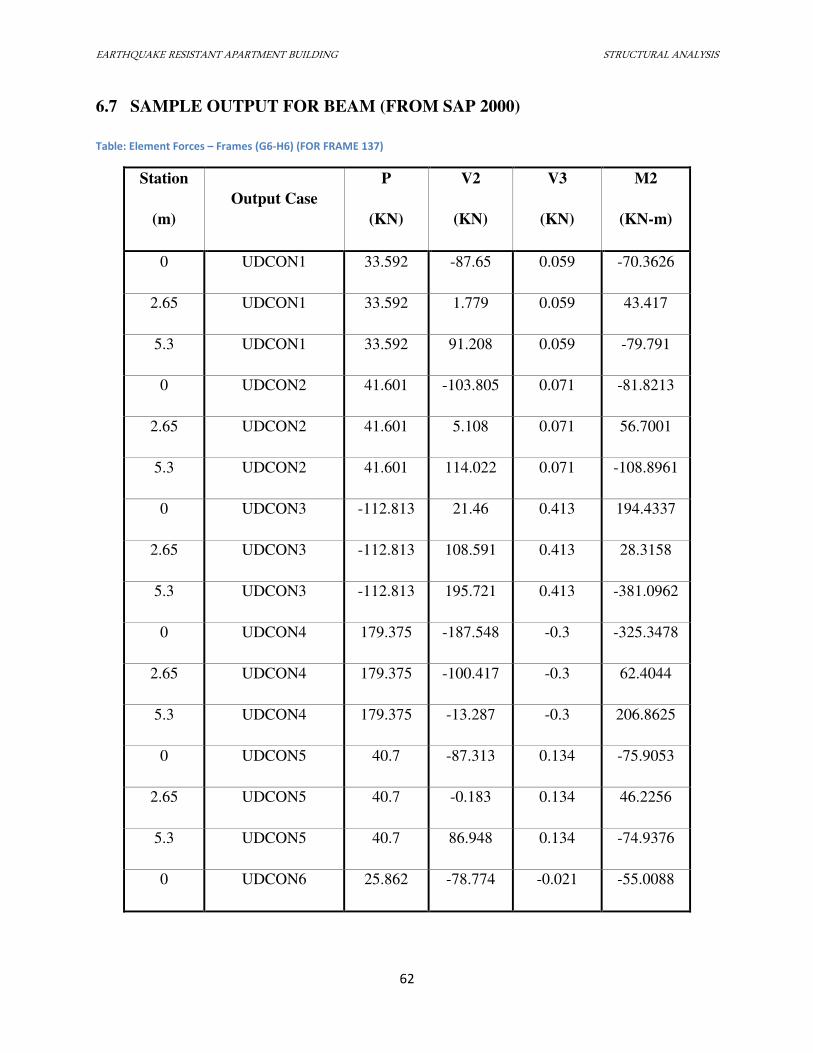
EARTHQUAKE RESISTANT APARTMENT BUILDING STRUCTURAL ANALYSIS
62
6.7 SAMPLE OUTPUT FOR BEAM (FROM SAP 2000)
Table: Element Forces – Frames (G6-H6) (FOR FRAME 137)
Station
(m)
Output Case
P
(KN)
V2
(KN)
V3
(KN)
M2
(KN-m)
0 UDCON1 33.592 -87.65 0.059 -70.3626
2.65 UDCON1 33.592 1.779 0.059 43.417
5.3 UDCON1 33.592 91.208 0.059 -79.791
0 UDCON2 41.601 -103.805 0.071 -81.8213
2.65 UDCON2 41.601 5.108 0.071 56.7001
5.3 UDCON2 41.601 114.022 0.071 -108.8961
0 UDCON3 -112.813 21.46 0.413 194.4337
2.65 UDCON3 -112.813 108.591 0.413 28.3158
5.3 UDCON3 -112.813 195.721 0.413 -381.0962
0 UDCON4 179.375 -187.548 -0.3 -325.3478
2.65 UDCON4 179.375 -100.417 -0.3 62.4044
5.3 UDCON4 179.375 -13.287 -0.3 206.8625
0 UDCON5 40.7 -87.313 0.134 -75.9053
2.65 UDCON5 40.7 -0.183 0.134 46.2256
5.3 UDCON5 40.7 86.948 0.134 -74.9376
0 UDCON6 25.862 -78.774 -0.021 -55.0088
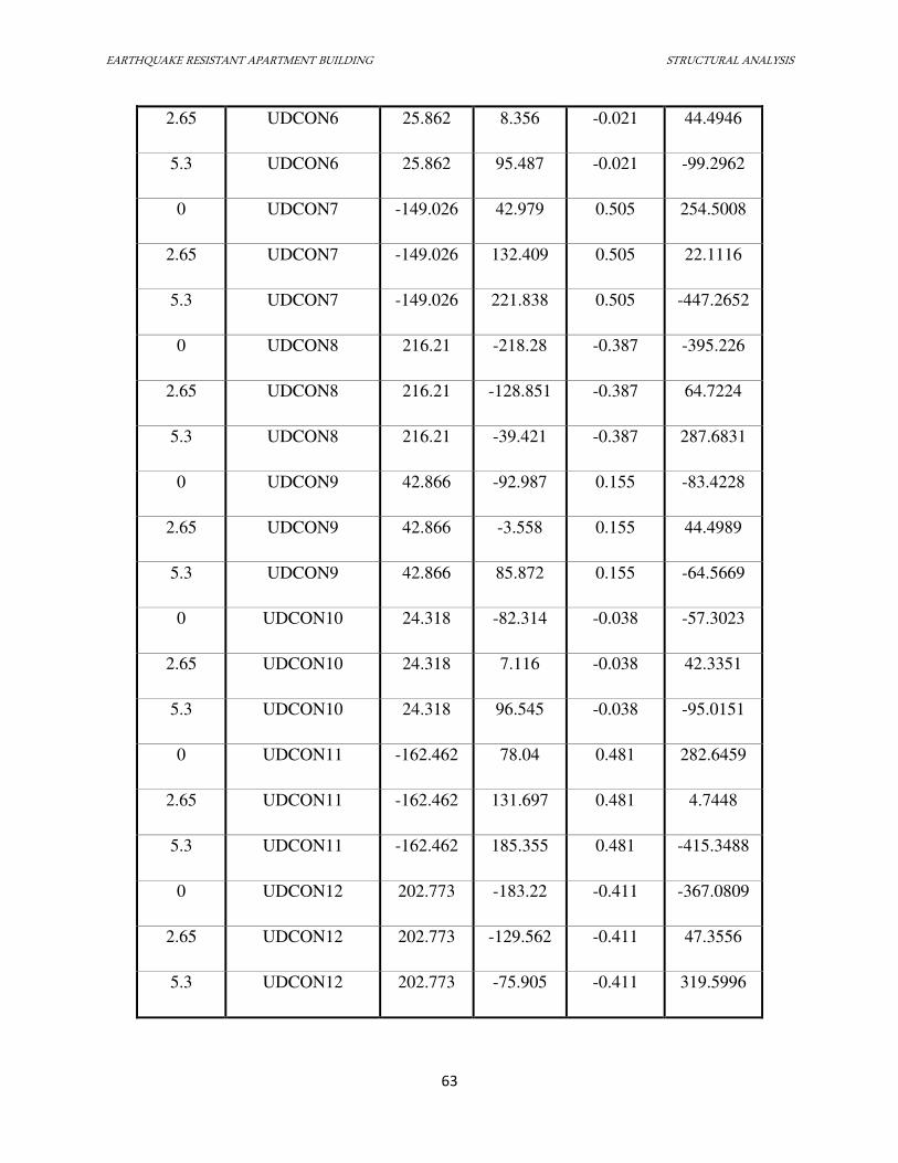
EARTHQUAKE RESISTANT APARTMENT BUILDING STRUCTURAL ANALYSIS
63
2.65 UDCON6 25.862 8.356 -0.021 44.4946
5.3 UDCON6 25.862 95.487 -0.021 -99.2962
0 UDCON7 -149.026 42.979 0.505 254.5008
2.65 UDCON7 -149.026 132.409 0.505 22.1116
5.3 UDCON7 -149.026 221.838 0.505 -447.2652
0 UDCON8 216.21 -218.28 -0.387 -395.226
2.65 UDCON8 216.21 -128.851 -0.387 64.7224
5.3 UDCON8 216.21 -39.421 -0.387 287.6831
0 UDCON9 42.866 -92.987 0.155 -83.4228
2.65 UDCON9 42.866 -3.558 0.155 44.4989
5.3 UDCON9 42.866 85.872 0.155 -64.5669
0 UDCON10 24.318 -82.314 -0.038 -57.3023
2.65 UDCON10 24.318 7.116 -0.038 42.3351
5.3 UDCON10 24.318 96.545 -0.038 -95.0151
0 UDCON11 -162.462 78.04 0.481 282.6459
2.65 UDCON11 -162.462 131.697 0.481 4.7448
5.3 UDCON11 -162.462 185.355 0.481 -415.3488
0 UDCON12 202.773 -183.22 -0.411 -367.0809
2.65 UDCON12 202.773 -129.562 -0.411 47.3556
5.3 UDCON12 202.773 -75.905 -0.411 319.5996
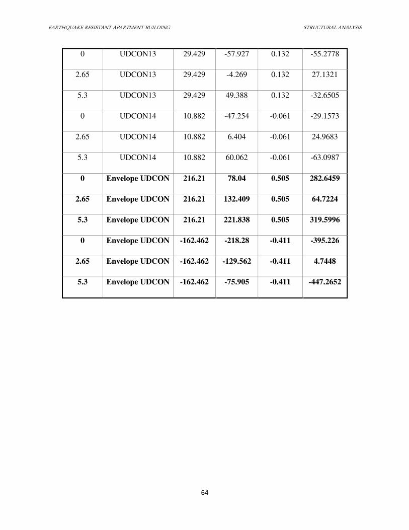
EARTHQUAKE RESISTANT APARTMENT BUILDING STRUCTURAL ANALYSIS
64
0 UDCON13 29.429 -57.927 0.132 -55.2778
2.65 UDCON13 29.429 -4.269 0.132 27.1321
5.3 UDCON13 29.429 49.388 0.132 -32.6505
0 UDCON14 10.882 -47.254 -0.061 -29.1573
2.65 UDCON14 10.882 6.404 -0.061 24.9683
5.3 UDCON14 10.882 60.062 -0.061 -63.0987
0 Envelope UDCON 216.21 78.04 0.505 282.6459
2.65 Envelope UDCON 216.21 132.409 0.505 64.7224
5.3 Envelope UDCON 216.21 221.838 0.505 319.5996
0 Envelope UDCON -162.462 -218.28 -0.411 -395.226
2.65 Envelope UDCON -162.462 -129.562 -0.411 4.7448
5.3 Envelope UDCON -162.462 -75.905 -0.411 -447.2652
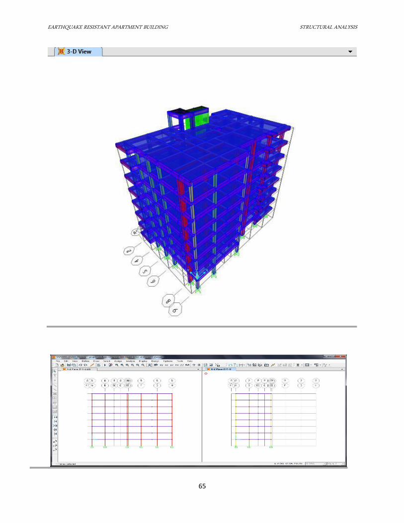
EARTHQUAKE RESISTANT APARTMENT BUILDING STRUCTURAL ANALYSIS
65
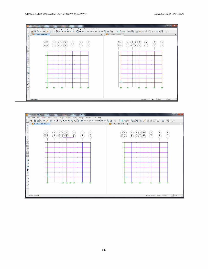
EARTHQUAKE RESISTANT APARTMENT BUILDING STRUCTURAL ANALYSIS
66
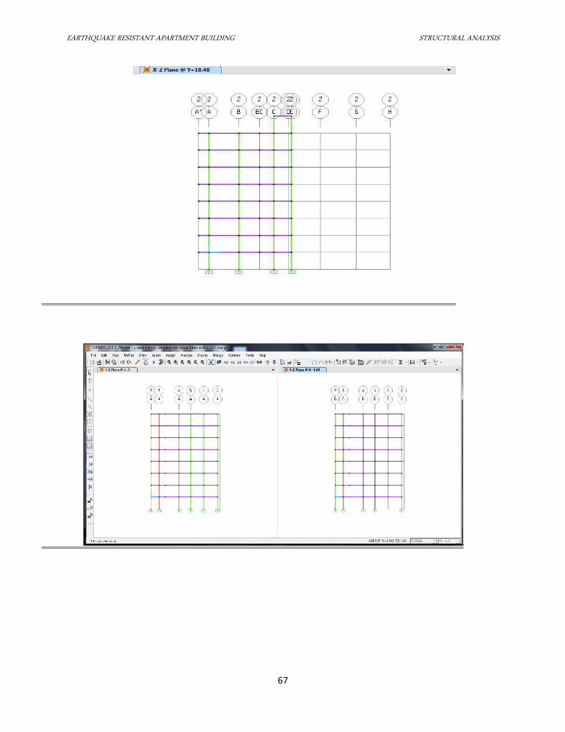
EARTHQUAKE RESISTANT APARTMENT BUILDING STRUCTURAL ANALYSIS
67
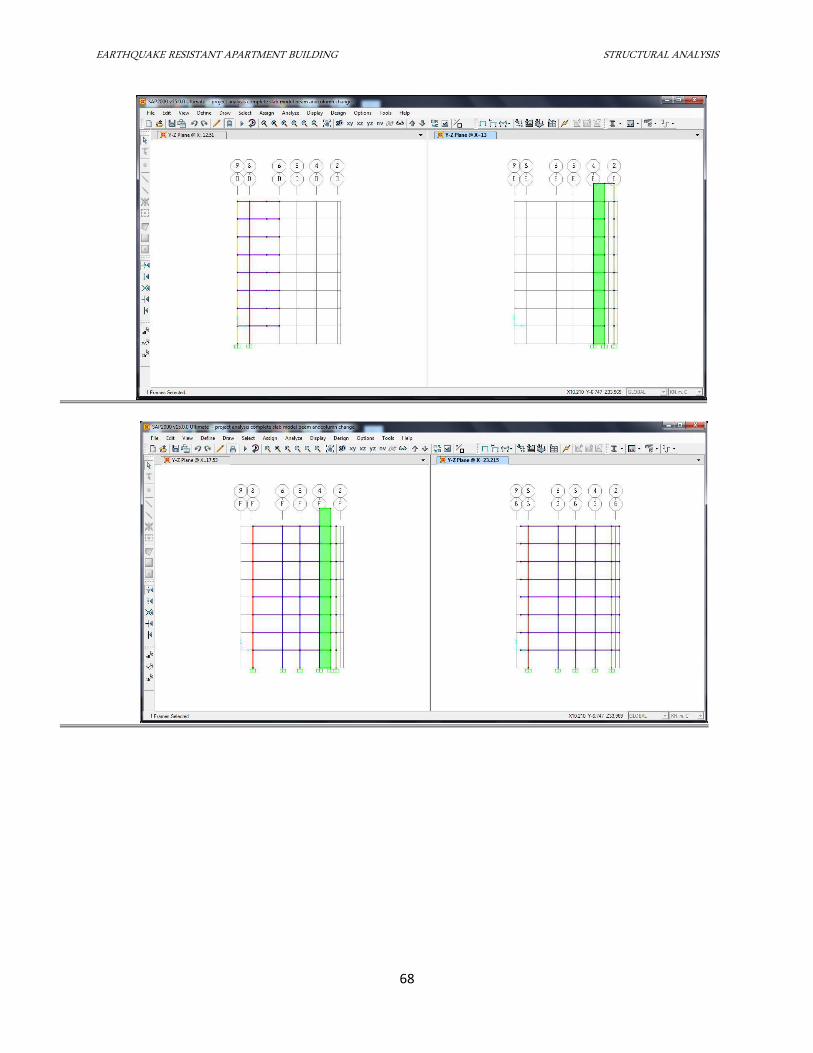
EARTHQUAKE RESISTANT APARTMENT BUILDING STRUCTURAL ANALYSIS
68
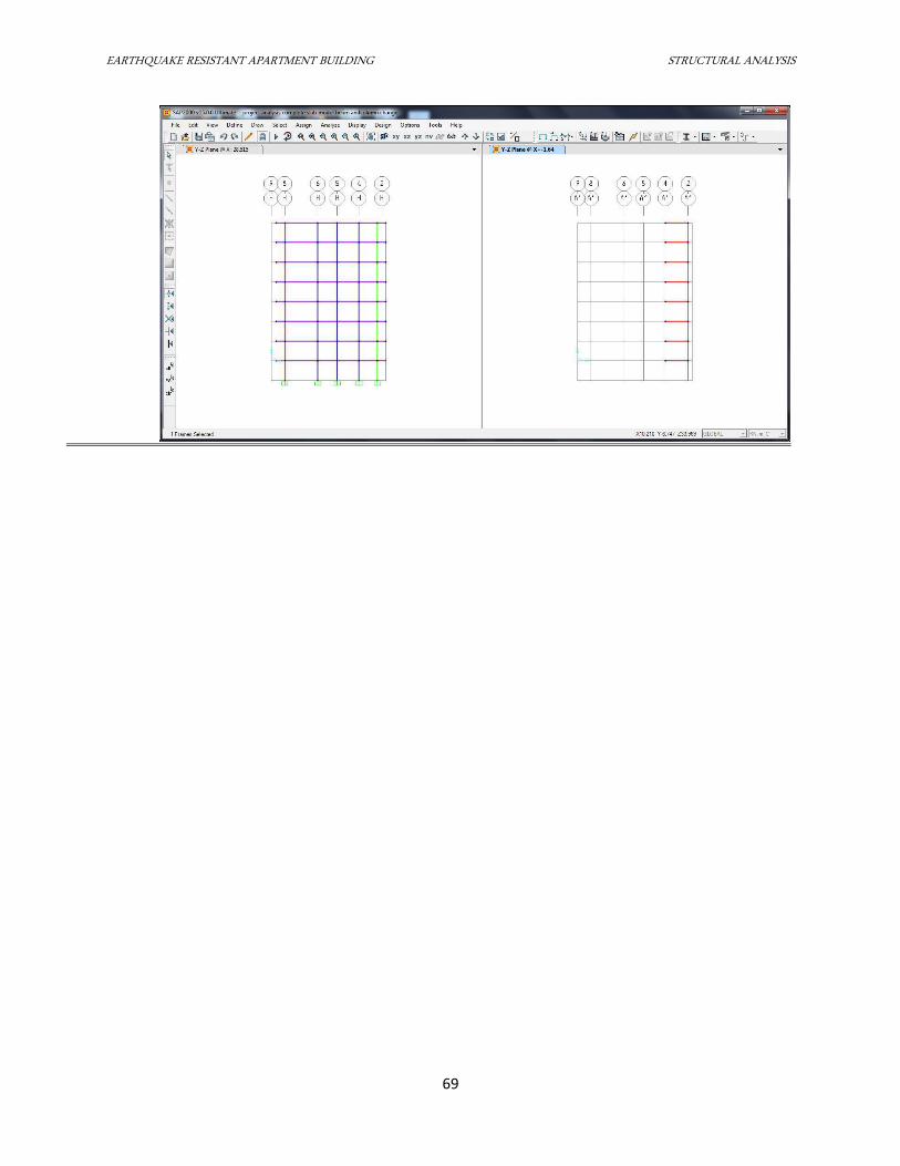
EARTHQUAKE RESISTANT APARTMENT BUILDING STRUCTURAL ANALYSIS
69
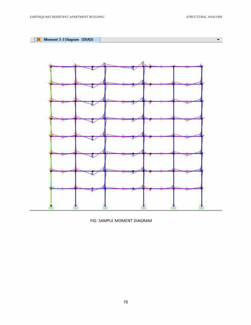
EARTHQUAKE RESISTANT APARTMENT BUILDING STRUCTURAL ANALYSIS
70
FIG: SAMPLE MOMENT DIAGRAM
EARTHQUAKE RESISTANT BUILDING DESIGN OF SLABS
71
7.1 DESIGN OF SLABS
7.1.1 INTRODUCTION
Slab is rigid plate which acts as roof or floor during the construction of building in which
all the points are equally displaced when the load is applied on a point on a slab. Slab is a
flexural element and there are mainly two types of slab based on the ratio of longer to shorter
span of room. They are as follows:
i. One way slab: It is the slab with the ratio of longer to shorter span greater than 2 and the
value of its coefficient can be used from Table 26.b (IS 456:2000).
ii. Two way slab: It is the slab with the ratio of longer to shorter span less than or equal to 2
and the value of its coefficient can be used from Table 26.a (IS 456:2000).
The span moment per unit width (which are considered as positive in sign) and the
negative moments at continuous edge for these slabs are calculated from the equation:
Mx=αxwlx2
from span lx
My=αywlx2 from span ly
Spacing of bars on slab:
i. Maximum spacing in main bar:
a) 3 times the effective depth
b) 300 mm, ; whichever is less
ii. Maximum spacing in distribution bars IS 456 Cl. 26.3.3
a) 5 times the effective depth
b) 450 mm, ; whichever is less
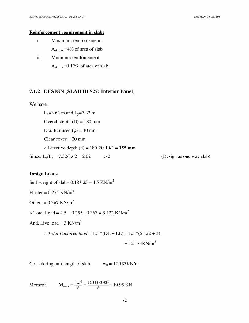
EARTHQUAKE RESISTANT BUILDING DESIGN OF SLABS
72
Reinforcement requirement in slab:
i. Maximum reinforcement:
Ast max =4% of area of slab
ii. Minimum reinforcement:
Ast min =0.12% of area of slab
7.1.2 DESIGN (SLAB ID S27: Interior Panel)
We have,
Lx=3.62 m and Ly=7.32 m
Overall depth (D) = 180 mm
Dia. Bar used (ɸ) = 10 mm
Clear cover = 20 mm ∴ Effective depth (d) = 180-20-10/2 = 155 mm
Since, Ly/Lx = 7.32/3.62 = 2.02 > 2 (Design as one way slab)
Design Loads
Self-weight of slab= 0.18* 25 = 4.5 KN/m2
Plaster = 0.255 KN/m2
Others = 0.367 KN/m2 ∴ Total Load = 4.5 + 0.255+ 0.367 = 5.122 KN/m
2
And, Live load = 3 KN/m2 ∴ Total Factored load = 1.5 *(DL + LL) = 1.5 *(5.122 + 3)
= 12.183KN/m2
Considering unit length of slab, wu = 12.183KN/m
Moment, Mmax = ���� =
. � ∗ .�� = 19.95 KN
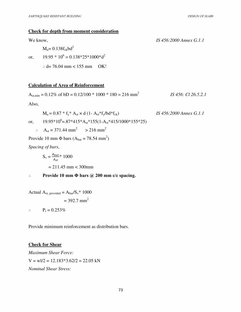
EARTHQUAKE RESISTANT BUILDING DESIGN OF SLABS
73
Check for depth from moment consideration
We know, IS 456:2000 Annex G.1.1
Mu= 0.138fckbd2
or, 19.95 * 106 = 0.138*25*1000*d
2 ∴ d= 76.04 mm < 155 mm OK!
Calculation of Area of Reinforcement
Ast,min = 0.12% of bD = 0.12/100 * 1000 * 180 = 216 mm2 IS 456: Cl 26.5.2.1
Also,
Mu = 0.87 * fy* Ast × d (1- Ast*fy/bd*fck) IS 456:2000 Annex G.1.1
or, 19.95*106=.87*415*Ast*155(1-Ast*415/1000*155*25) ∴ Ast = 371.44 mm
2 > 216 mm
2
Provide 10 mm Φ bars (Abar = 78.54 mm2)
Spacing of bars,
Sv = �� * 1000
= 211.45 mm < 300mm ∴ Provide 10 mm Φ bars @ 200 mm c/c spacing.
Actual Ast, provided = Abar/Sv* 1000
= 392.7 mm2 ∴ Pt = 0.253%
Provide minimum reinforcement as distribution bars.
Check for Shear
Maximum Shear Force:
V = wl/2 = 12.183*3.62/2 = 22.05 kN
Nominal Shear Stress:
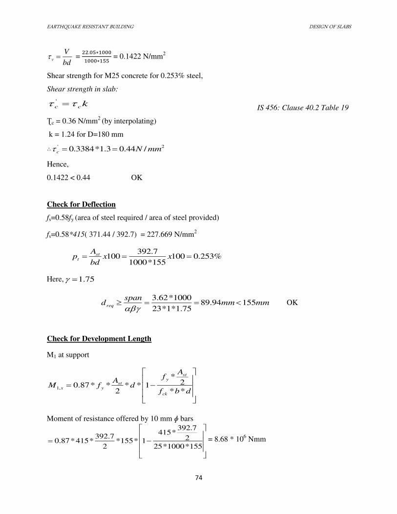
EARTHQUAKE RESISTANT BUILDING DESIGN OF SLABS
74
bd
Vv =
. ∗∗ = 0.1422 N/mm2
Shear strength for M25 concrete for 0.253% steel,
Shear strength in slab:
kcc '
IS 456: Clause 40.2 Table 19
Ʈc = 0.36 N/mm2
(by interpolating)
k = 1.24 for D=180 mm ∴ 2' /44.03.1*3384.0 mmNc
Hence,
0.1422 < 0.44 OK
Check for Deflection
fs=0.58fy (area of steel required / area of steel provided)
fs=0.58*415( 371.44 / 392.7) = 227.669 N/mm2
%253.0100155*1000
7.392100 xx
bd
Ap st
t
Here, 75.1
mmmmspan
dreq 15594.8975.1*1*23
1000*62.3
OK
Check for Development Length
M1 at support
Moment of resistance offered by 10 mm ɸ bars
155*1000*25
2
7.392*415
1*155*2
7.392*415*87.0 = 8.68 * 10
6 Nmm
dbf
Af
dA
fMck
sty
styx
**
2*
1**2
**87.0,1
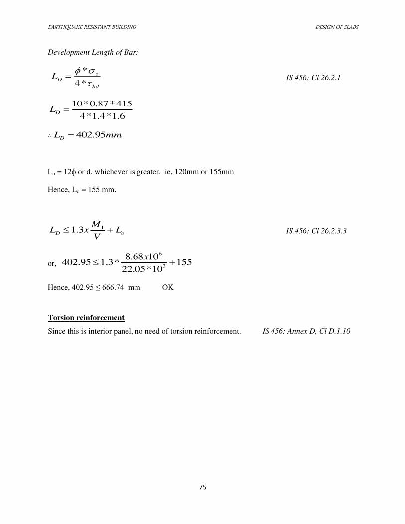
EARTHQUAKE RESISTANT BUILDING DESIGN OF SLABS
75
Development Length of Bar:
bd
sDL
*4
* IS 456: Cl 26.2.1
6.1*4.1*4
415*87.0*10DL
∴ mmLD 95.402
Lo = 12ɸ or d, whichever is greater. ie, 120mm or 155mm
Hence, Lo = 155 mm.
oD LV
MxL 13.1 IS 456: Cl 26.2.3.3
or, 15510*05.22
1068.8*3.195.402
3
6
x
Hence, 402.95 ≤ 666.74 mm OK
Torsion reinforcement
Since this is interior panel, no need of torsion reinforcement. IS 456: Annex D, Cl D.1.10
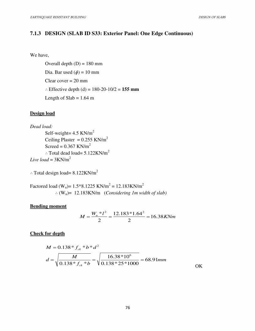
EARTHQUAKE RESISTANT BUILDING DESIGN OF SLABS
76
7.1.3 DESIGN (SLAB ID S33: Exterior Panel: One Edge Continuous)
We have,
Overall depth (D) = 180 mm
Dia. Bar used (ɸ) = 10 mm
Clear cover = 20 mm ∴ Effective depth (d) = 180-20-10/2 = 155 mm
Length of Slab = 1.64 m
Design load
Dead load:
Self-weight= 4.5 KN/m2
Ceiling Plaster = 0.255 KN/m2
Screed = 0.367 KN/m2
∴ Total dead load= 5.122KN/m2
Live load = 3KN/m2
∴ Total design load= 8.122KN/m2
Factored load (Wu)= 1.5*8.1225 KN/m2 = 12.183KN/m
2
∴ (Wu)= 12.183KN/m (Considering 1m width of slab)
Bending moment
KNmlW
M u 38.162
64.1*183.12
2
* 22
Check for depth
2***138.0 dbfM ck
mmbf
Md
ck
91.681000*25*138.0
10*38.16
**138.0
6
OK
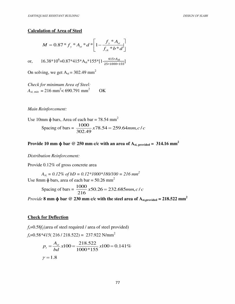
EARTHQUAKE RESISTANT BUILDING DESIGN OF SLABS
77
Calculation of Area of Steel
dbf
AfdAfM
ck
sty
sty**
*1****87.0
or, 16.38*106=0.87*415*Ast*155*[1-
∗�∗ ∗ ]
On solving, we get Ast = 302.49 mm2
Check for minimum Area of Steel:
Ast, min = 216 mm2< 690.791 mm
2 OK
Main Reinforcement:
Use 10mm ɸ bars, Area of each bar = 78.54 mm2
Spacing of bars = ccmmx /,64.25954.7849.302
1000
Provide 10 mm ɸ bar @ 250 mm c/c with an area of Ast, provided = 314.16 mm2
Distribution Reinforcement:
Provide 0.12% of gross concrete area
Ast, = 0.12% of bD = 0.12*1000*180/100 = 216 mm2
Use 8mm ɸ bars, area of each bar = 50.26 mm2
Spacing of bars = ccmmx /,685.23226.50216
1000
Provide 8 mm ɸ bar @ 230 mm c/c with the steel area of Ast,provided = 218.522 mm2
Check for Deflection
fs=0.58fy(area of steel required / area of steel provided)
fs=0.58*415( 216 / 218.522) = 237.922 N/mm2
%141.0100155*1000
522.218100 xx
bd
Ap st
t
8.1
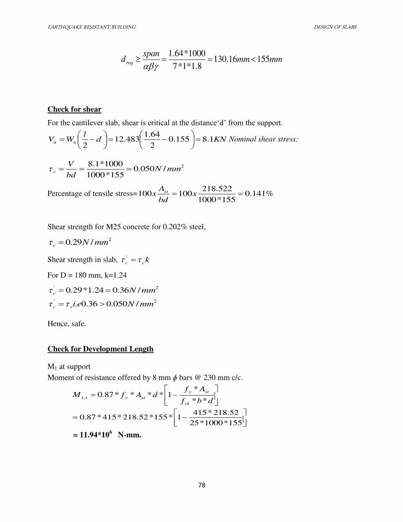
EARTHQUAKE RESISTANT BUILDING DESIGN OF SLABS
78
mmmmspan
dreq 15516.1308.1*1*7
1000*64.1
Check for shear
For the cantilever slab, shear is critical at the distance‘d’ from the support.
KNdl
WV uu 1.8155.02
64.1483.12
2
Nominal shear stress:
2/050.0155*1000
1000*1.8mmN
bd
Vv
Percentage of tensile stress= %141.0155*1000
522.218100100 x
bd
Ax st
Shear strength for M25 concrete for 0.202% steel,
2/29.0 mmNc
Shear strength in slab, kcc '
For D = 180 mm, k=1.24
2' /36.024.1*29.0 mmNc
2' /050.036.0. mmNeivc
Hence, safe.
Check for Development Length
M1 at support
Moment of resistance offered by 8 mm ɸ bars @ 230 mm c/c.
dbf
AfdAfM
ck
sty
styx**
*1****87.0,1
155*1000*25
52.218*4151*155*52.218*415*87.0
= 11.94*106
N-mm.
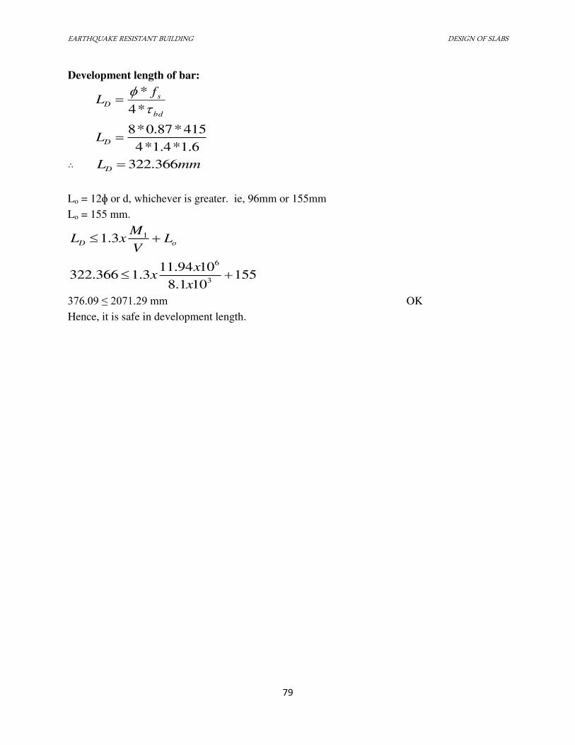
EARTHQUAKE RESISTANT BUILDING DESIGN OF SLABS
79
Development length of bar:
bd
sD
fL
*4
*
6.1*4.1*4
415*87.0*8DL
∴ mmLD 366.322
Lo = 12ɸ or d, whichever is greater. ie, 96mm or 155mm
Lo = 155 mm.
oD LV
MxL 13.1
155101.8
1094.113.1366.322
3
6
x
xx
376.09 ≤ 2071.29 mm OK
Hence, it is safe in development length.
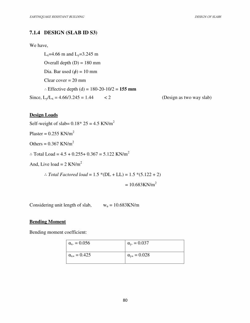
EARTHQUAKE RESISTANT BUILDING DESIGN OF SLABS
80
7.1.4 DESIGN (SLAB ID S3)
We have,
Lx=4.66 m and Ly=3.245 m
Overall depth (D) = 180 mm
Dia. Bar used (ɸ) = 10 mm
Clear cover = 20 mm ∴ Effective depth (d) = 180-20-10/2 = 155 mm
Since, Ly/Lx = 4.66/3.245 = 1.44 < 2 (Design as two way slab)
Design Loads
Self-weight of slab= 0.18* 25 = 4.5 KN/m2
Plaster = 0.255 KN/m2
Others = 0.367 KN/m2 ∴ Total Load = 4.5 + 0.255+ 0.367 = 5.122 KN/m
2
And, Live load = 2 KN/m2 ∴ Total Factored load = 1.5 *(DL + LL) = 1.5 *(5.122 + 2)
= 10.683KN/m2
Considering unit length of slab, wu = 10.683KN/m
Bending Moment
Bending moment coefficient:
αx- = 0.056 αy- = 0.037
αx+ = 0.425 αy+ = 0.028
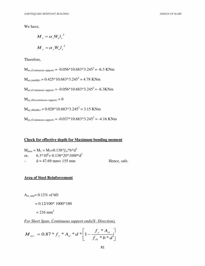
EARTHQUAKE RESISTANT BUILDING DESIGN OF SLABS
81
We have,
2
xuxx lWM
2
xuyy lWM
Therefore,
Mux,(Continuous support) = -0.056*10.683*3.2452
= -6.3 KNm
Mux,(middle) = 0.425*10.683*3.2452 = 4.78 KNm
Mux,(Continuous support) = -0.056*10.683*3.2452
= -6.3KNm
Muy,(Discontinuous support) = 0
Muy,(Middle) = 0.028*10.683*3.2452 = 3.15 KNm
Muy,(Continuous support) = -0.037*10.683*3.2452 = -4.16 KNm
Check for effective depth for Maximum bending moment
Mmax = M1 = M3=0.138*fck*b*d2
or, 6.3*106= 0.138*20*1000*d
2 ∴ d = 47.69 mm< 155 mm Hence, safe.
Area of Steel Reinforcement
Ast, min= 0.12% of bD
= 0.12/100* 1000*180
= 216 mm2
For Short Span: Continuous support ends(X- Direction),
dbf
AfdAfM
ck
sty
styux**
*1****87.0
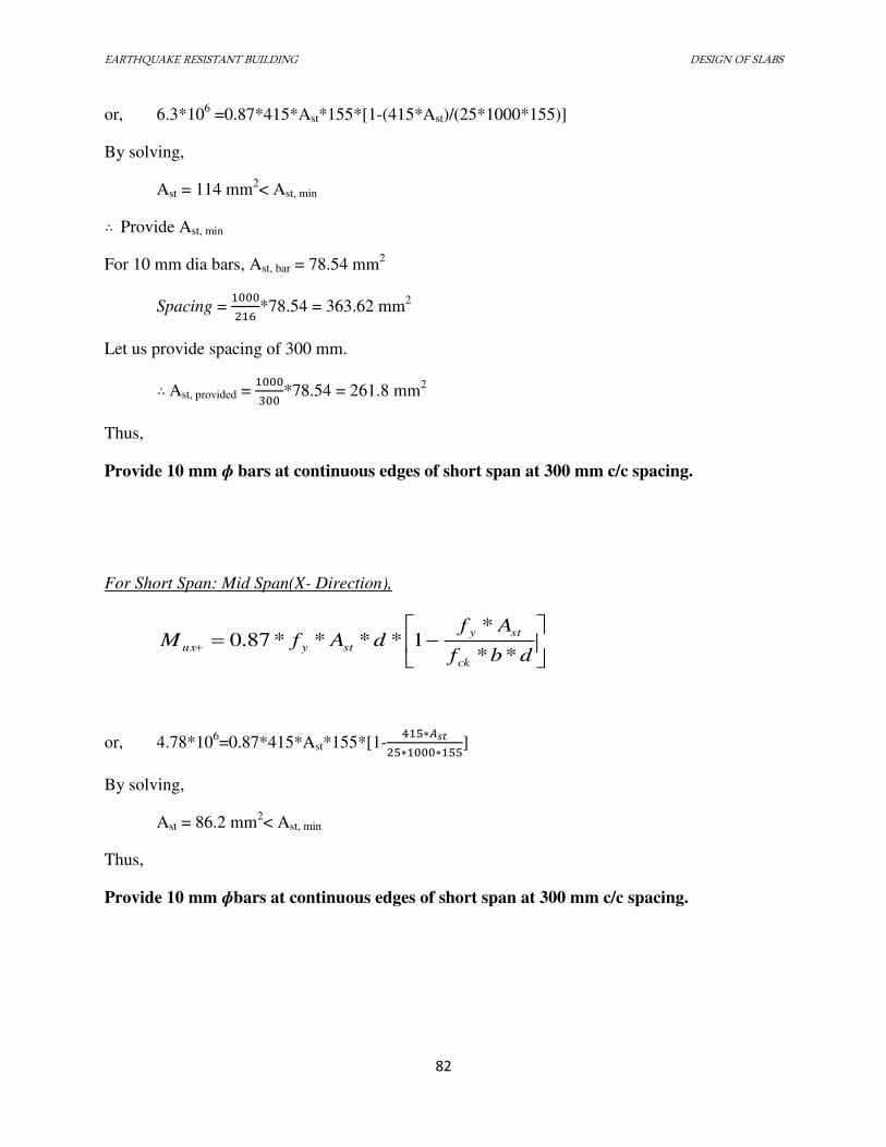
EARTHQUAKE RESISTANT BUILDING DESIGN OF SLABS
82
or, 6.3*106 =0.87*415*Ast*155*[1-(415*Ast)/(25*1000*155)]
By solving,
Ast = 114 mm2< Ast, min ∴ Provide Ast, min
For 10 mm dia bars, Ast, bar = 78.54 mm2
Spacing = *78.54 = 363.62 mm2
Let us provide spacing of 300 mm. ∴ Ast, provided = *78.54 = 261.8 mm2
Thus,
Provide 10 mm ɸ bars at continuous edges of short span at 300 mm c/c spacing.
For Short Span: Mid Span(X- Direction),
dbf
AfdAfM
ck
sty
styux**
*1****87.0
or, 4.78*106=0.87*415*Ast*155*[1-
∗�∗ ∗ ]
By solving,
Ast = 86.2 mm2< Ast, min
Thus,
Provide 10 mm ɸbars at continuous edges of short span at 300 mm c/c spacing.
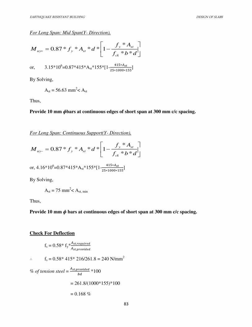
EARTHQUAKE RESISTANT BUILDING DESIGN OF SLABS
83
For Long Span: Mid Span(Y- Direction),
dbf
AfdAfM
ck
sty
styuy**
*1****87.0
or, 3.15*106=0.87*415*Ast*155*[1-
∗�∗ ∗ ]
By Solving,
Ast = 56.63 mm2< Ast
Thus,
Provide 10 mm ɸbars at continuous edges of short span at 300 mm c/c spacing.
For Long Span: Continuous Support(Y- Direction),
dbf
AfdAfM
ck
sty
styuy**
*1****87.0
or, 4.16*106=0.87*415*Ast*155*[1-
∗�∗ ∗ ]
By Solving,
Ast = 75 mm2< Ast, min
Thus,
Provide 10 mm ɸ bars at continuous edges of short span at 300 mm c/c spacing.
Check For Deflection
fs = 0.58* fy*� , �� , �
∴ fs = 0.58* 415* 216/261.8 = 240 N/mm2
% of tension steel = � , ��� *100
= 261.8/(1000*155)*100
= 0.168 %
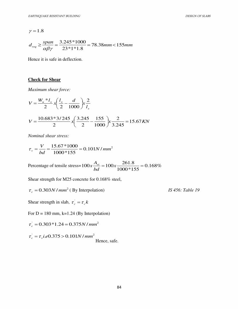
EARTHQUAKE RESISTANT BUILDING DESIGN OF SLABS
84
8.1
mmmmspan
dreq 15538.788.1*1*23
1000*245.3
Hence it is safe in deflection.
Check for Shear
Maximum shear force:
x
xxu
lx
dlx
lWV
2
100022
*
KNxxV 67.15245.3
2
1000
155
2
245.3
2
245/3*683.10
Nominal shear stress:
2/101.0155*1000
1000*67.15mmN
bd
Vv
Percentage of tensile stress= %168.0155*1000
8.261100100 x
bd
Ax st
Shear strength for M25 concrete for 0.168% steel,
2/303.0 mmNc ( By Interpolation) IS 456: Table 19
Shear strength in slab, kcc '
For D = 180 mm, k=1.24 (By Interpolation)
2' /375.024.1*303.0 mmNc
2' /101.0375.0. mmNeivc Hence, safe.
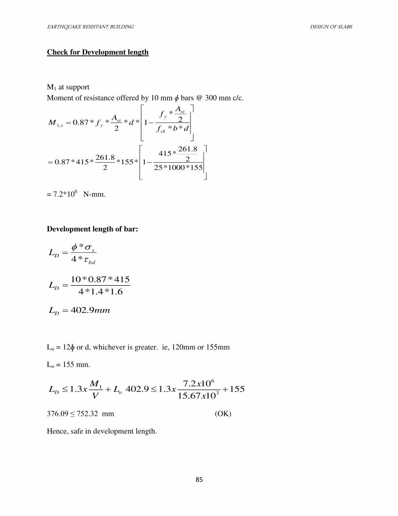
EARTHQUAKE RESISTANT BUILDING DESIGN OF SLABS
85
Check for Development length
M1 at support
Moment of resistance offered by 10 mm ɸ bars @ 300 mm c/c.
dbf
Af
dA
fMck
sty
styx
**
2*
1**2
**87.0,1
155*1000*25
2
8.261*415
1*155*2
8.261*415*87.0
= 7.2*106
N-mm.
Development length of bar:
bd
sDL
*4
*
6.1*4.1*4
415*87.0*10DL
mmLD 9.402
Lo = 12ɸ or d, whichever is greater. ie, 120mm or 155mm
Lo = 155 mm.
oD LV
MxL 13.1 155
1067.15
102.73.19.402
3
6
x
xx
376.09 ≤ 752.32 mm (OK)
Hence, safe in development length.
EARTHQUAKE RESISTANT BUILDING DESIGN OF SLABS
86
Calculation of Torsion Reinforcement
Length, lx = 3245 mm
Length of torsion reinforcement in both direction = 0.375 lx = 0.2*3245 = 1216.87 mm
Maximum Positive Steel Area, Ast = 261.8 mm2
In the corner, Steel area required = 0.75*Ast = 0.75*261.8 = 162.6 mm2
Use 8 mm ɸ bar,
Area of each bar = 3.1416*82/4 = 50.24 mm
2
Provide 8 mm ɸ bar @ spacing = 1216.87*50.24/162.6 = 375.99 mm c/c
Adopt spacing as 300 mm c/c < 3d or 300, whichever is smaller.
Provide 8 mm ɸ bar at 300 mm c/c
EARTHQUAKE RESISTANT BUILDING DESIGN OF COLUMN
87
7.2 DESIGN OF COLUMN
7.2.1 INTRODUCTION
The column section shall be designed just above and just below the beam column joints and
larger of the two reinforcements shall be adopted. The end moments and end shear are available
from computer analysis. The design moment should include the following:
a. The additional moment if any, due to long column effect as per Cl.39.7 of IS 456:2000
b. The moments due to minimum eccentricity as per Cl.25.4 of IS 456:2000
All columns are subjected to biaxial moments and biaxial shears. The longitudinal
reinforcements are designed for axial force and biaxial moment as per IS 456:2000. Since
analysis is carried out considering center line dimension, it is necessary to calculate moments at
the top or at the bottom face of the beam intersecting the column for economy. The critical load
combination may be obtained by inspection of analysis result.
The columns in our building are of various sizes and 34 in number. The procedure used for
exact design of members subjected to axial load and biaxial bending is extremely laborious.
Therefore, IS 456:2000 permits the design of such members by the following equations:
(�� ��⁄ )α
+ (�� ��⁄ )α ≤1
Puz =0.45*fck *Ac + 0.75*fy*Ast
where,
Mux= moment about X axis
Muy= moment about Y axis
Muxl= maximum uniaxial moment capacity in X axis
EARTHQUAKE RESISTANT BUILDING DESIGN OF COLUMN
88
Muyl= maximum uniaxial moment capacity in Y axis
fck= characteristic strength of concrete
fy= characteristic strength of steel
Ac= gross X-section area of column
Ast =area of reinforcement bars
7.2.2 DESIGN: Ground floor (F4 column)
Here,
Clear height (h) = 3.3 m
Unsupported length (l) = 3.3 – 0.7 = 2.6 m
Effective length (le) = 0.65l = 0.65 × 2.6 = 1.69 m
So,
� = �� = 9 = . < Hence, the column is short.
From SAP2000,
Axial force (Pu) = -4762.515 KN
Moment along X-direction (Mux) = 349.661 KNm
Moment along Y-direction (Muy) = 319.262 KNm
Minimum reinforcement = 0.8% of BD = 0.008 × 600 × 600 = 2880 mm2
Maximum reinforcement = 4% of BD = 0.04 × 600 × 600 = 14400 mm2
Maximum reinforcement in extreme case = 6% of BD = 0.06 × 600 × 600 = 21600 mm2
Minimum eccentricity, ex,min = ey,min = + � = + = 25.2 mm > 20 mm
Moment due to minimum eccentricity = Pu × ex,min = 4762.515 × 25.2 = 120.02 KNm <
Mux and Muy
EARTHQUAKE RESISTANT BUILDING DESIGN OF COLUMN
89
So, take Mux = 349.661 KNm, Muy = 319.262 KNm
Here, ��� �� = . ∗ ∗ ∗ = .
Assume, d’ = 40 + 32/2 = 56 mm (Assume 40 mm clear cover and 32 mm Φ bar), ∴ d’/D = 0.1
p = 2%, ���� = = . ,
Assume equal reinforcement on all four sides.
From SP16 Chart 44, ����� �2 = .
∴ Mux,lim = Muy,lim = 0.07 × 25 × 600 × 6002
= 378 KNm
Pz = 0.45fckAc + 0.75fyAsc = 0.45 × 25 × 600 × 600 + 0.75 × 415 × 0.02 × 6002 = 6291
KN
For ���� = . , αn = 1.928 (IS 456 Cl. 39.6)
We know, ���� ,�� + ���� ,
�� = . . + . . = . ≫
Hence for another trial, adopt p = 3%
∴ ���� = .
From SP16 Chart 44, ����� �2 = .
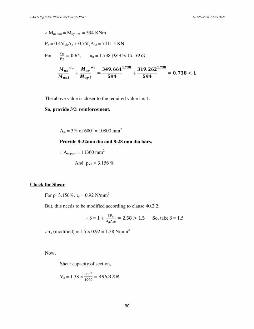
EARTHQUAKE RESISTANT BUILDING DESIGN OF COLUMN
90
∴ Mux,lim = Muy,lim = 594 KNm
Pz = 0.45fckAc + 0.75fyAsc = 7411.5 KN
For ���� = . , αn = 1.738 (IS 456 Cl. 39.6) ���� ,
�� + ���� ,�� = . . + . . = . <
The above value is closer to the required value i.e. 1.
So, provide 3% reinforcement.
Ast = 3% of 6002 = 10800 mm
2
Provide 8-32mm dia and 8-28 mm dia bars. ∴ Ast,prov = 11360 mm2
And, pact = 3.156 %
Check for Shear
For p=3.156%, τc = 0.92 N/mm2
But, this needs to be modified according to clause 40.2.2: ∴ δ = + ������ = . > . So, take δ = 1.5
∴ τc (modified) = 1.5 × 0.92 = 1.38 N/mm2
Now,
Shear capacity of section,
Vc = 1.38 × 2 = . ��
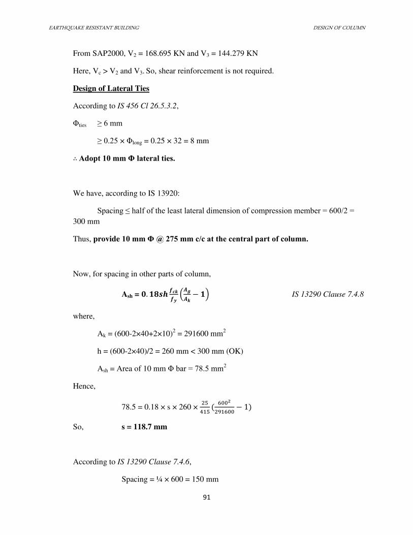
EARTHQUAKE RESISTANT BUILDING DESIGN OF COLUMN
91
From SAP2000, V2 = 168.695 KN and V3 = 144.279 KN
Here, Vc > V2 and V3. So, shear reinforcement is not required.
Design of Lateral Ties
According to IS 456 Cl 26.5.3.2,
Φties ≥ 6 mm
≥ 0.25 × Φlong = 0.25 × 32 = 8 mm ∴ Adopt 10 mm Φ lateral ties.
We have, according to IS 13920:
Spacing ≤ half of the least lateral dimension of compression member = 600/2 =
300 mm
Thus, provide 10 mm Φ @ 275 mm c/c at the central part of column.
Now, for spacing in other parts of column,
Ash = . � � �� − IS 13290 Clause 7.4.8
where,
Ak = (600-2×40+2×10)2 = 291600 mm
2
h = (600-2×40)/2 = 260 mm < 300 mm (OK)
Ash = Area of 10 mm Φ bar = 78.5 mm2
Hence,
78.5 = 0.18 × s × 260 × 29 −
So, s = 118.7 mm
According to IS 13290 Clause 7.4.6,
Spacing = ¼ × 600 = 150 mm
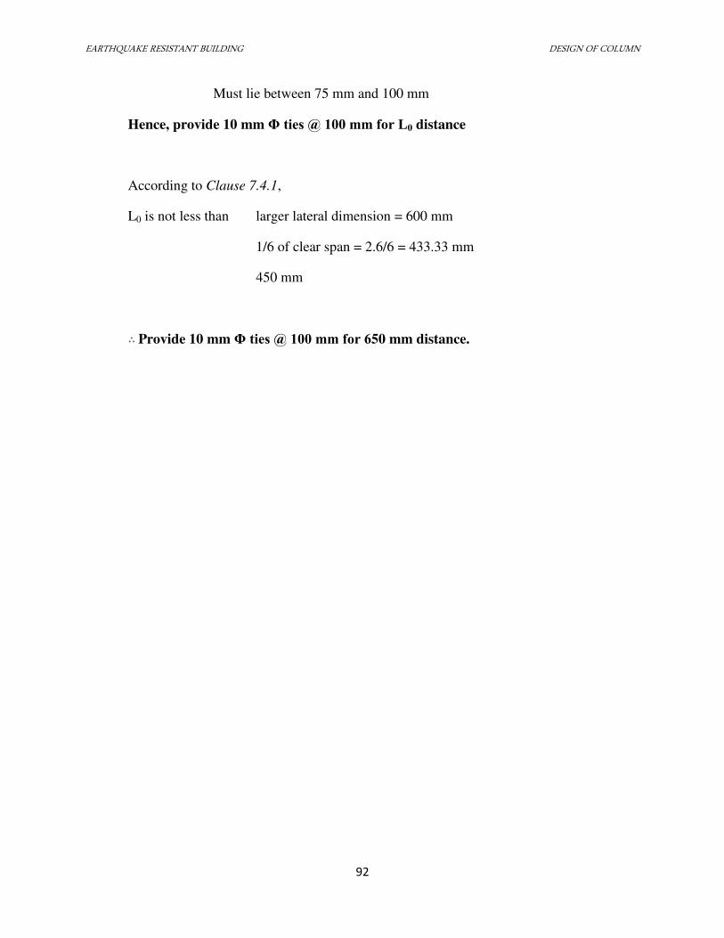
EARTHQUAKE RESISTANT BUILDING DESIGN OF COLUMN
92
Must lie between 75 mm and 100 mm
Hence, provide 10 mm Φ ties @ 100 mm for L0 distance
According to Clause 7.4.1,
L0 is not less than larger lateral dimension = 600 mm
1/6 of clear span = 2.6/6 = 433.33 mm
450 mm
∴ Provide 10 mm Φ ties @ 100 mm for 650 mm distance.
EARTHQUAKE RESISTANT BUILDING DESIGN OF BEAM
93
7.3 BEAM DESIGN
7.3.1 INTRODUCTION
The beam is flexural member which distributes the vertical load to the column and resists
the bending moment. The design of the beam deals with the determination of the beam section
and the steel required.
For convenience, we have considered all the sections as under-reinforced ones and
rectangular sections. The singly reinforced and doubly reinforced sections are designed as per the
requirement, i.e. comparison with the limiting moment, Mu, lim.
IS 456:2000 (Annex G, Cl.38.1) can be referred for the calculation of the required steel in
the beam. For the singly reinforced section, steel is calculated by using the formula from G.1.1.b.
Mu =0.87×fy×Ast×d×[1- Ast × fy/(b×D×fck)]
Limiting moment of the resistance is given by the equation:
Mu, lim =0.36xu,max/d ×(1-0.42 xu,max /d)bd2 fck
For the section with the compression reinforcement, where the ultimate moment of
resistance of the section exceeds the limiting value Mu, lim, the compression reinforcement may
be obtained by:
Mu - Mu, lim =fsc ×Asc (d-d’)
where,
Mu= ultimate moment of resistance of the section
Mu, lim =limiting moment of resistance
xu=neutral axis depth
EARTHQUAKE RESISTANT BUILDING DESIGN OF BEAM
94
xu,max=limiting value of xu
D= effective depth
d= width of the compression face
d’= effective cover
fy= characteristic strength of the reinforcement
fck= characteristic strength of concrete
fsc=design stress in compression reinforcement corresponding to strain of 0.0035×( xu,max-
d’)/ xu,max
Ast=area of the tension reinforcement
Asc= area of compression reinforcement
Total area of tension reinforcement in the doubly reinforced beam sections shall be
obtained by
Ast=Ast1 - Ast2
where,
Ast=total tension reinforcement
Ast1=area of tensile reinforcement for singly reinforced section for Mu, lim
Ast2= Asc× fsc/0.87fy
Similarly, IS 13920:1993 is also referred for the calculation of minimum and maximum
reinforcement and shear force for the formation of plastic hinge.
SP 16 is also used as a design aid for calculations of limiting moments and area of
reinforcement.

EARTHQUAKE RESISTANT BUILDING DESIGN OF BEAM
95
7.3.2 DESIGN OF BEAM (ID = G6-H6 or 137)
Here,
D=700mm B=400mm > 250mm OK IS13920:1993 cl 6.1.3
Provide Nominal cover=25 mm
Hence, d = 700-25-28/2=661 (Assuming 28 mm dia bars)
Also, B/D=0.57 >0.3 IS13920:1993 cl 6.1.2
L=5.3m
And, L/D=7.57 >4 OK IS13920:1993 cl 6.1.4
Minimum reinforcement:
Ast,min = 0.24×fck1/2
/fy = 0.289% = 764.116 mm2
IS13920:1993 cl 6.2.1.b
Maximum reinforcement:
Ast,max = 0.025Bd = 6610mm2 IS13920:1993 cl 6.2.2
FLEXURE DESIGN:
We have,
Mu,lim = 3.46bd2=604.24 KN-m
A) At left end:
Hogging:
From SAP2000, Mu=395.226KN-m Mt=5.948 KN-m ∴ Mu>Mt So, design Mu = Mu+Mt = 401.174 KN-m
Also, Mu<Mu,lim. Hence, it should be designed as a singly reinforced section.

EARTHQUAKE RESISTANT BUILDING DESIGN OF BEAM
96
Here, Mu/bd2=2.295
From Table 3 of SP16, pt=0.7412% (top) (-ve steel)
Sagging:
From SAP2000, Mu=282.64KN-m Mt=5.948 KN-m ∴ Mu>Mt So, design Mu = Mu+Mt = 288.58 KN-m
Also, Mu<Mu,lim. Hence, it should be designed as a singly reinforced section.
Here, Mu/bd2=1.65
From Table 3 of SP16, pb=0.499% (bottom)
Here, pb=0.499% > (-ve steel/2) OK IS13920:1993 cl. 6.2.3
B) At middle:
Hogging:
From SAP2000, Mu=0KN-m Mt=5.948 KN-m
Hence, -ve steel is not required.
But, provide Ast,min ie 0.289% i.e. pt= 0.289% (top)(-ve steel)
Sagging:
From SAP2000, Mu=64.722KN-m Mt=5.948 KN-m ∴ Mu>Mt So, design Mu = Mu+Mt = 70.67 KN-m
Also, Mu<Mu,lim. Hence, it should be designed as a singly reinforced section.
Here, Mu/bd2=0.466
From Table 3 of SP16, pb=0.1318%
Adopt Ast,min ie 0.289% i.e. pb= 0.289%
EARTHQUAKE RESISTANT BUILDING DESIGN OF BEAM
97
Here, pb=0.2899% > (-ve steel/2) OK IS13920:1993 cl. 6.2.3
C) At right end:
Hogging:
From SAP2000, Mu=447.26 KN-m Mt=5.948 KN-m ∴ Mu>Mt So, design Mu = Mu+Mt = 453.208 KN-m
Also, Mu<Mu,lim. Hence, it should be designed as a singly reinforced section.
Here, Mu/bd2=2.593
From Table 3 of SP16, pt=0.834% (top) (-ve steel)
Sagging:
From SAP2000, Mu=319.599 KN-m Mt=5.948 KN-m ∴ Mu>Mt So, design Mu = Mu+Mt = 325.547 KN-m
Also, Mu<Mu,lim. Hence, it should be designed as a singly reinforced section.
Here, Mu/bd2=1.863
From Table 3 of SP16, pb=0.587% (bottom)
Here, pb=0.5% > (-ve steel/2) OK IS13920:1993 cl. 6.2.3
Adopt 22 mm dia bars with Ast = 374.94 mm2
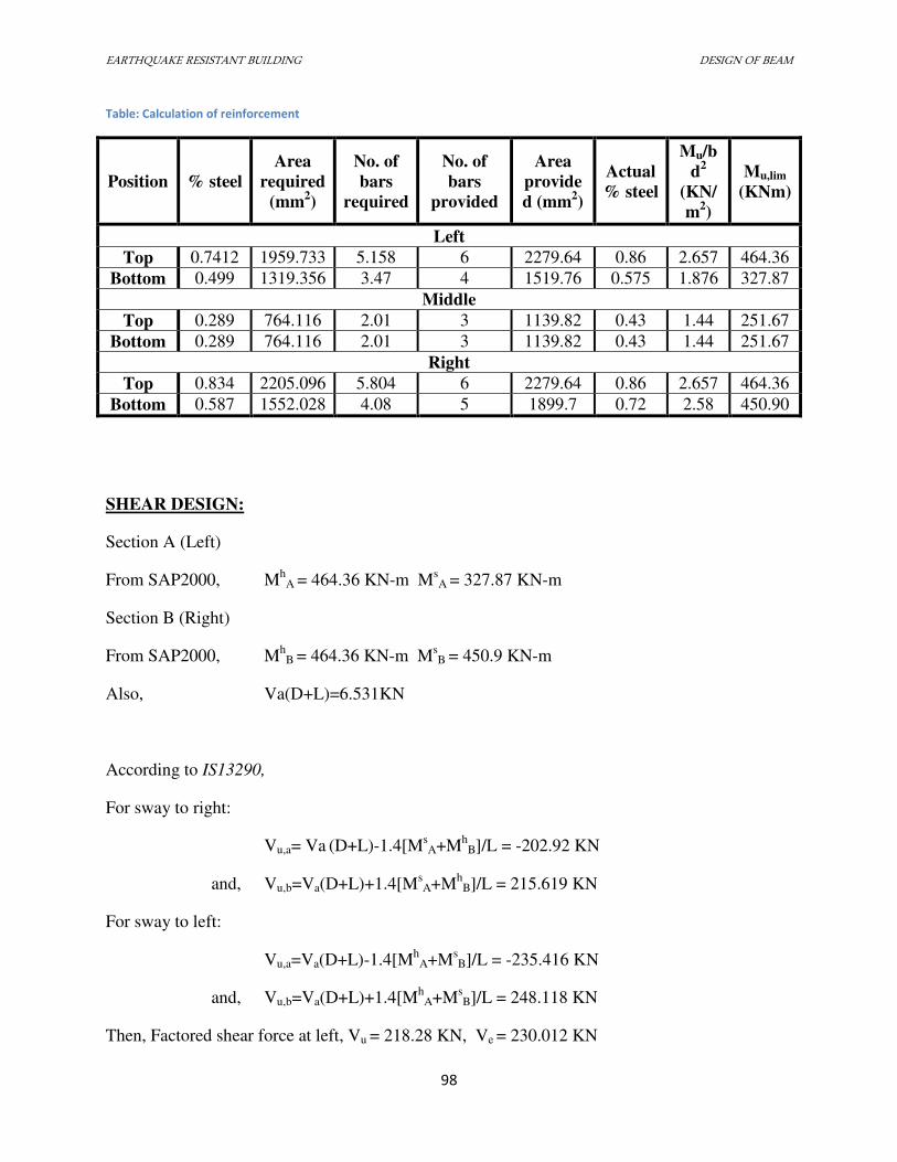
EARTHQUAKE RESISTANT BUILDING DESIGN OF BEAM
98
Table: Calculation of reinforcement
Position % steel
Area
required
(mm2)
No. of
bars
required
No. of
bars
provided
Area
provide
d (mm2)
Actual
% steel
Mu/b
d2
(KN/
m2)
Mu,lim
(KNm)
Left
Top 0.7412 1959.733 5.158 6 2279.64 0.86 2.657 464.36
Bottom 0.499 1319.356 3.47 4 1519.76 0.575 1.876 327.87
Middle
Top 0.289 764.116 2.01 3 1139.82 0.43 1.44 251.67
Bottom 0.289 764.116 2.01 3 1139.82 0.43 1.44 251.67
Right
Top 0.834 2205.096 5.804 6 2279.64 0.86 2.657 464.36
Bottom 0.587 1552.028 4.08 5 1899.7 0.72 2.58 450.90
SHEAR DESIGN:
Section A (Left)
From SAP2000, Mh
A = 464.36 KN-m MsA = 327.87 KN-m
Section B (Right)
From SAP2000, Mh
B = 464.36 KN-m MsB = 450.9 KN-m
Also, Va(D+L)=6.531KN
According to IS13290,
For sway to right:
Vu,a= Va (D+L)-1.4[M
sA+M
hB]/L = -202.92 KN
and, Vu,b=Va(D+L)+1.4[MsA+M
hB]/L = 215.619 KN
For sway to left:
Vu,a=Va(D+L)-1.4[Mh
A+MsB]/L = -235.416 KN
and, Vu,b=Va(D+L)+1.4[Mh
A+MsB]/L = 248.118 KN
Then, Factored shear force at left, Vu = 218.28 KN, Ve = 230.012 KN
EARTHQUAKE RESISTANT BUILDING DESIGN OF BEAM
99
Factored shear force at right, Vu=221.838 KN, Ve=233.57 KN
Determination of shear reinforcement:
a. Left:
We have, Vu= 235.416 KN
pt=0.86%
τ=0.601 N/mm2 From Table 19, IS456
τ c,max=3.1N/mm2
We know, τ,v=Vu/bd = 0.928 N/mm2
Also, Vus = Vu-τcbd = 76.512 KN
Taking 8 mm two legged stirrups,
Spacing = 313.57 mm IS456 cl 40.4
We know,
Spacing must be < d/4 = 661/4 = 165.25mm
< 8 × minimum dia = 8 × 22 = 176mm
< 100 mm
So, adopt 100 mm spacing.
b. Right:
We have, Vu = 248.118 KN
pt = 0.86%
τ = 0.601 N/mm2 From Table 19, IS456
τ c,max = 3.1N/mm2
τ c,max=3.1N/mm2
We know, τ,v=Vu/bd = 0.928 N/mm2
EARTHQUAKE RESISTANT BUILDING DESIGN OF BEAM
100
Also, Vus = Vu-τcbd = 89.214 KN
Taking 8 mm two legged stirrups,
Spacing = 268.93 mm IS456 cl 40.4
We know,
Spacing must be < d/4 = 661/4 = 165.25mm
< 8 × minimum dia = 8 × 22 = 176mm
< 100 mm
So, adopt 100 mm spacing.
Beyond 2d from support, provide minimum reinforcement of d/2 = 330 mm (Say 300 mm)
DEVELOPMENT LENGTH:
τbd = 1.4 × 1.6 = 2.24 N/mm2 (tension)
τbd = 2.24 × 1.25 = 2.8 N/mm2 (compression)
According to IS 456 cl 26.2.1:
Development length (Ld)= dia × 0.87 fy / (4× τbd)
For tension, Ld= 886.5 mm
For compression, Ld = 709.2 mm
For bending, Ld+ 10 db = 1106.5 mm.
DESIGN OF SIDEFACE REINFORCEMENT:
Since D>450, provide 0.1% of bD steel along vertical sides. ∴ Asv = 0.001 × 400 × 700 = 280 mm2
Hence provide 2-16mm dia bars.
Actual Area = 402.12 mm2
EARTHQUAKE RESISTANT BUILDING DESIGN OF BEAM
101
7.3.3 DESIGN OF BEAM (ID = G6-G8 or 141)
Here,
D=700mm B=400mm > 250mm OK IS13920:1993 cl 6.1.3
Provide Nominal cover=25 mm
Hence, d = 700-25-28/2=661 (Assuming 28 mm dia bars)
Also, B/D=0.57>0.3 IS13920:1993 cl 6.1.2
L=5.54m
And, L/D=7.91 > 4 OK IS13920:1993 cl 6.1.4
Minimum reinforcement:
Ast,min = 0.24×fck1/2
/fy = 0.289% = 764.116 mm2
IS13920:1993 cl 6.2.1.b
Maximum reinforcement:
Ast,max = 0.025Bd = 6610mm2 IS13920:1993 cl 6.2.2
FLEXURE DESIGN:
We have,
Mu,lim = 3.46bd2=604.24 KN-m
A) At left end:
Hogging:
From SAP2000, Mu=502.347 KN-m Mt = 19.876 KN-m ∴ Mu>Mt So, design Mu = Mu+Mt = 522.223 KN-m
Also, Mu<Mu,lim. Hence, it should be designed as a singly reinforced section.
EARTHQUAKE RESISTANT BUILDING DESIGN OF BEAM
102
Here, Mu/bd2=2.99
From Table 3 of SP16, pt=0.992% (top) (-ve steel)
Sagging:
From SAP2000, Mu = 331.651 KN-m Mt = 19.876 KN-m ∴ Mu>Mt So, design Mu = Mu+Mt = 355.527 KN-m
Also, Mu<Mu,lim. Hence, it should be designed as a singly reinforced section.
Here, Mu/bd2=2.03
From Table 3 of SP16, pb=0.629% (bottom)
Here, pb=0.629% > (-ve steel/2) OK IS13920:1993 cl. 6.2.3
B) At middle:
Hogging:
From SAP2000, Mu=0KN-m Mt=5.948 KN-m
Hence, -ve steel is not required.
But, provide Ast,min ie 0.289% i.e. pt= 0.289% (top)(-ve steel)
Sagging:
From SAP2000, Mu = 52.9811KN-m Mt=19.876 KN-m ∴ Mu>Mt So, design Mu = Mu+Mt = 72.857 KN-m
Also, Mu<Mu,lim. Hence, it should be designed as a singly reinforced section.
Here, Mu/bd2=0.417
From Table 3 of SP16, pb=0.118%
Adopt Ast,min ie 0.289% i.e. pb= 0.289%
EARTHQUAKE RESISTANT BUILDING DESIGN OF BEAM
103
Here, pb=0.289% > (-ve steel/2) OK IS13920:1993 cl. 6.2.3
C) At right end:
Hogging:
From SAP2000, Mu=420.895 KN-m Mt=19.876 KN-m ∴ Mu>Mt So, design Mu = Mu+Mt = 440.771 KN-m
Also, Mu<Mu,lim. Hence, it should be designed as a singly reinforced section.
Here, Mu/bd2=2.52
From Table 3 of SP16, pt=0.807% (top) (-ve steel)
Sagging:
From SAP2000, Mu= 365.52 KN-m Mt=19.876 KN-m ∴ Mu>Mt So, design Mu = Mu+Mt = 385.396 KN-m
Also, Mu<Mu,lim. Hence, it should be designed as a singly reinforced section.
Here, Mu/bd2=2.205
From Table 3 of SP16, pb=0.691% (bottom)
Here, pb=0.691% > (-ve steel/2) OK IS13920:1993 cl. 6.2.3
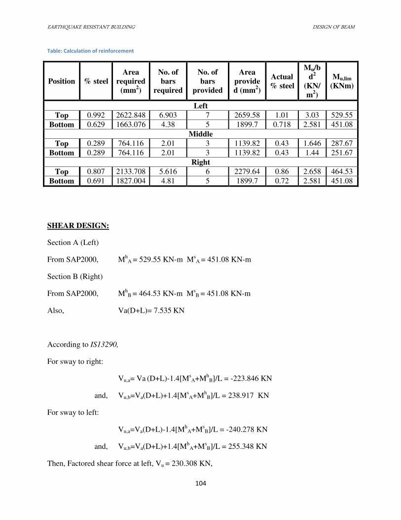
EARTHQUAKE RESISTANT BUILDING DESIGN OF BEAM
104
Table: Calculation of reinforcement
Position % steel
Area
required
(mm2)
No. of
bars
required
No. of
bars
provided
Area
provide
d (mm2)
Actual
% steel
Mu/b
d2
(KN/
m2)
Mu,lim
(KNm)
Left
Top 0.992 2622.848 6.903 7 2659.58 1.01 3.03 529.55
Bottom 0.629 1663.076 4.38 5 1899.7 0.718 2.581 451.08
Middle
Top 0.289 764.116 2.01 3 1139.82 0.43 1.646 287.67
Bottom 0.289 764.116 2.01 3 1139.82 0.43 1.44 251.67
Right
Top 0.807 2133.708 5.616 6 2279.64 0.86 2.658 464.53
Bottom 0.691 1827.004 4.81 5 1899.7 0.72 2.581 451.08
SHEAR DESIGN:
Section A (Left)
From SAP2000, Mh
A = 529.55 KN-m MsA = 451.08 KN-m
Section B (Right)
From SAP2000, Mh
B = 464.53 KN-m MsB = 451.08 KN-m
Also, Va(D+L)= 7.535 KN
According to IS13290,
For sway to right:
Vu,a= Va (D+L)-1.4[M
sA+M
hB]/L = -223.846 KN
and, Vu,b=Va(D+L)+1.4[MsA+M
hB]/L = 238.917 KN
For sway to left:
Vu,a=Va(D+L)-1.4[Mh
A+MsB]/L = -240.278 KN
and, Vu,b=Va(D+L)+1.4[Mh
A+MsB]/L = 255.348 KN
Then, Factored shear force at left, Vu = 230.308 KN,
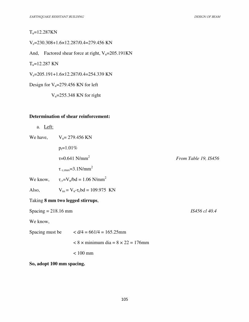
EARTHQUAKE RESISTANT BUILDING DESIGN OF BEAM
105
Tu=12.287KN
Ve=230.308+1.6×12.287/0.4=279.456 KN
And, Factored shear force at right, Vu=205.191KN
Tu=12.287 KN
Ve=205.191+1.6×12.287/0.4=254.339 KN
Design for Vu=279.456 KN for left
Vu=255.348 KN for right
Determination of shear reinforcement:
a. Left:
We have, Vu= 279.456 KN
pt=1.01%
τ=0.641 N/mm2 From Table 19, IS456
τ c,max=3.1N/mm2
We know, τ,v=Vu/bd = 1.06 N/mm2
Also, Vus = Vu-τcbd = 109.975 KN
Taking 8 mm two legged stirrups,
Spacing = 218.16 mm IS456 cl 40.4
We know,
Spacing must be < d/4 = 661/4 = 165.25mm
< 8 × minimum dia = 8 × 22 = 176mm
< 100 mm
So, adopt 100 mm spacing.
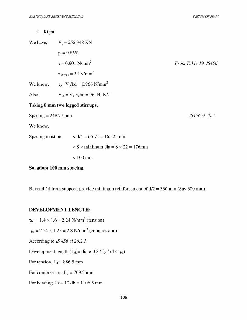
EARTHQUAKE RESISTANT BUILDING DESIGN OF BEAM
106
a. Right:
We have, Vu = 255.348 KN
pt = 0.86%
τ = 0.601 N/mm2 From Table 19, IS456
τ c,max = 3.1N/mm2
We know, τ,v=Vu/bd = 0.966 N/mm2
Also, Vus = Vu-τcbd = 96.44 KN
Taking 8 mm two legged stirrups,
Spacing = 248.77 mm IS456 cl 40.4
We know,
Spacing must be < d/4 = 661/4 = 165.25mm
< 8 × minimum dia = 8 × 22 = 176mm
< 100 mm
So, adopt 100 mm spacing.
Beyond 2d from support, provide minimum reinforcement of d/2 = 330 mm (Say 300 mm)
DEVELOPMENT LENGTH:
τbd = 1.4 × 1.6 = 2.24 N/mm2 (tension)
τbd = 2.24 × 1.25 = 2.8 N/mm2 (compression)
According to IS 456 cl 26.2.1:
Development length (Ld)= dia × 0.87 fy / (4× τbd)
For tension, Ld= 886.5 mm
For compression, Ld = 709.2 mm
For bending, Ld+ 10 db = 1106.5 mm.
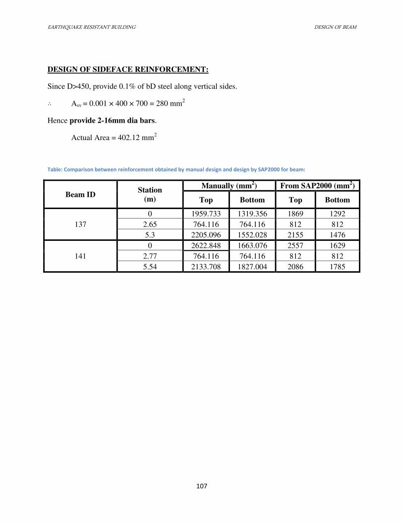
EARTHQUAKE RESISTANT BUILDING DESIGN OF BEAM
107
DESIGN OF SIDEFACE REINFORCEMENT:
Since D>450, provide 0.1% of bD steel along vertical sides. ∴ Asv = 0.001 × 400 × 700 = 280 mm2
Hence provide 2-16mm dia bars.
Actual Area = 402.12 mm2
Table: Comparison between reinforcement obtained by manual design and design by SAP2000 for beam:
Beam ID Station
(m)
Manually (mm2) From SAP2000 (mm
2)
Top Bottom Top Bottom
137
0 1959.733 1319.356 1869 1292
2.65 764.116 764.116 812 812
5.3 2205.096 1552.028 2155 1476
141
0 2622.848 1663.076 2557 1629
2.77 764.116 764.116 812 812
5.54 2133.708 1827.004 2086 1785
EARTHQUAKE RESISTANT BUILDING DESIGN OF STAIRCASE
108
7.4 DESIGN OF STAIRCASE
7.4.1 INTRODUCTION
A staircase is a construction designed to bridge a large vertical distance by dividing it
into smaller vertical distances, called steps. The geometrical forms of staircase may be different
depending upon the requirement.
In our case, there are two types of staircases: dog-legged and open well staircase.
In the dog-legged case, the stair is spanning transversely in which, supports to the stairs are
provided parallel to the riser at the top and bottom of the stairs. However, in the open well case,
effective length and loading is taken as per Clause 33.2 of IS 456:2000.
Stair slabs are generally designed to resist dead load, live load. Design of stair
case can be carried out according to IS:456:2000 by considering effective length, distribution of
loading and depth of section.
STAIRCASE 1 (Dog Legged Staircase)
Number of Tread = 9
Number of Riser = 9+1 = 10
Floor to Floor height = 3.3 m
Height of one flight = .
= 1.65 m
Steps of riser = = 165 mm
Total span = 3.85 m =3850 mm
Width of stairs = = 1195 mm
Taking, Tread (T) = 210 mm, ∴ Landing Width = (3850-9*210)/2 = 980 mm
EARTHQUAKE RESISTANT BUILDING DESIGN OF STAIRCASE
109
Effective Span
The stairs slab span transversely.
Hence, according to IS 456:2000 Cl. 33.1 c,
Effective Span = Centre –to-centre distance of supporting beams and walls
= 3850 mm
Loads
Thickness of waist slab is to be th to th span. i.e. 3850 mm.
Let us take D =220 mm
Assume 20 mm clear cover and 12mm dia bars.
Hence, d = 220-20-12/2 = 194 mm.
Let us find load per metre horizontal width of stairs.
Weight of waist slab = 0.22 * √ +
*25
=6.99 KN/m
Weight of steps = *. ∗ .. * 25
= 2.06 KN /m
Dead load = 6.99 + 2.06 = 9.05 KN/m
In the going portion with finishing load, let us take
DL = 10 KN/m
In landing portion,
DL = 0.22 * 1 * 25 = 5.5 KN/m
With finishing material, it may be taken as = 6.5 KN/m
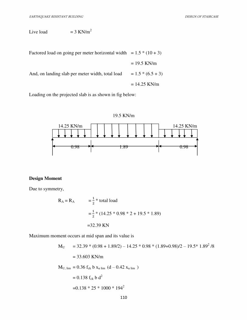
EARTHQUAKE RESISTANT BUILDING DESIGN OF STAIRCASE
110
Live load = 3 KN/m2
Factored load on going per meter horizontal width = 1.5 * (10 + 3)
= 19.5 KN/m
And, on landing slab per meter width, total load = 1.5 * (6.5 + 3)
= 14.25 KN/m
Loading on the projected slab is as shown in fig below:
19.5 KN/m
14.25 KN/m 14.25 KN/m
0.98 1.89 0.98
Design Moment
Due to symmetry,
RA = RA = * total load
= * (14.25 * 0.98 * 2 + 19.5 * 1.89)
=32.39 KN
Maximum moment occurs at mid span and its value is
MU = 32.39 * (0.98 + 1.89/2) – 14.25 * 0.98 * (1.89+0.98)/2 – 19.5* 1.892 /8
= 33.603 KN/m
MU, lim = 0.36 fck b xu lim (d – 0.42 xu lim )
= 0.138 fck b d2
=0.138 * 25 * 1000 * 1942
EARTHQUAKE RESISTANT BUILDING DESIGN OF STAIRCASE
111
=129.84 * 106 N-mm > MU OK!
Hence, the section can be designed as singly reinforced.
Reinforcement
Let Ast be the area of reinforcement required.
Then, = . �� � � − � �
or, 33.603*106 = 0.87 * 415 * Ast *194 * − A ∗∗ ∗
Solving above equation, we get,
Ast = 501.19 mm2 > 264 mm
2 (More than minimum Ast ie. 0.12%)
OK!
Using 12mm dia bars, spacing required � = �⁄ ∗ . ∗ = 225.66 mm
Provide 12mm φ bars at 220 mm c/c.
Distribution Steel
Ast =0.12 percent of gross sectional area
=. ∗ ∗
= 264 mm2
Using 10 mm bars, Spacing required � = �⁄ ∗ ∗ = 297 mm
Provide 10mm φ bars at 290 mm c/c.
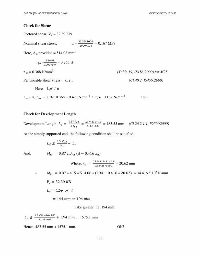
EARTHQUAKE RESISTANT BUILDING DESIGN OF STAIRCASE
112
Check for Shear
Factored shear, Vu = 32.39 KN
Nominal shear stress, τv = . ∗∗ = 0.167 MPa
Here, Ast provided = 514.08 mm2 ∴ pt =
.∗ = 0.265 %
τ uv = 0.368 N/mm2 (Table 19, IS456:2000) for M25
Permissible shear stress = ks τ uv (Cl.40.2, IS456:2000)
Here, ks=1.16
τ uc = ks τ uv = 1.16* 0.368 = 0.427 N/mm2 > τv ie. 0.167 N/mm
2 OK!
Check for Development Length
Development Length, = . �� � = . ∗ ∗ ∗ . ∗ . = 483.55 mm (Cl.26.2.1.1, IS456:2000)
At the simply supported end, the following condition shall be satisfied:
≤ . � ,� +
And, , = . ��� � − . � Where, � = . ∗ ∗ .. ∗ ∗ = 20.62 mm
∴ , = . ∗ ∗ . ∗ − . ∗ . = 34.416 * 106 N-mm
� = .
= � �� �
= �� �� ��
Take greater. i.e. 194 mm.
≤ . ∗ . ∗ 6. ∗ + �� = 1575.1 mm
Hence, 483.55 mm < 1575.1 mm. OK!
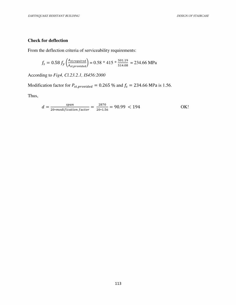
EARTHQUAKE RESISTANT BUILDING DESIGN OF STAIRCASE
113
Check for deflection
From the deflection criteria of serviceability requirements:
� = . �� (� , �� , � ) = 0.58 * 415 * .. = 234.66 MPa
According to Fig4, Cl.23.2.1, IS456:2000
Modification factor for � , � = . % and � = . MPa is 1.56.
Thus,
� = ∗ � � � = ∗ . = . < OK!
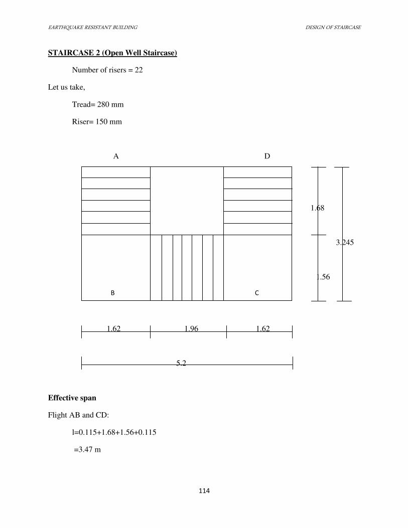
EARTHQUAKE RESISTANT BUILDING DESIGN OF STAIRCASE
114
STAIRCASE 2 (Open Well Staircase)
Number of risers = 22
Let us take,
Tread= 280 mm
Riser= 150 mm
A D
1.68
3.245
1.56
1.62 1.96 1.62
5.2
Effective span
Flight AB and CD:
l=0.115+1.68+1.56+0.115
=3.47 m
B C
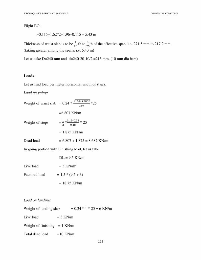
EARTHQUAKE RESISTANT BUILDING DESIGN OF STAIRCASE
115
Flight BC:
l=0.115+1.62*2+1.96+0.115 = 5.43 m
Thickness of waist slab is to be th to th of the effective span. i.e. 271.5 mm to 217.2 mm.
(taking greater among the spans. i.e. 5.43 m)
Let us take D=240 mm and d=240-20-10/2 =215 mm. (10 mm dia bars)
Loads
Let us find load per meter horizontal width of stairs.
Load on going:
Weight of waist slab = 0.24 * √ +
*25
=6.807 KN/m
Weight of steps = *. ∗ .. * 25
= 1.875 KN /m
Dead load = 6.807 + 1.875 = 8.682 KN/m
In going portion with Finishing load, let us take
DL = 9.5 KN/m
Live load = 3 KN/m2
Factored load = 1.5 * (9.5 + 3)
= 18.75 KN/m
Load on landing:
Weight of landing slab = 0.24 * 1 * 25 = 6 KN/m
Live load = 3 KN/m
Weight of finishing = 1 KN/m
Total dead load =10 KN/m
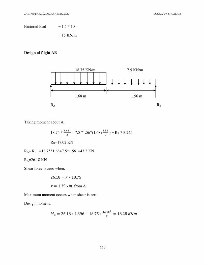
EARTHQUAKE RESISTANT BUILDING DESIGN OF STAIRCASE
116
Factored load = 1.5 * 10
= 15 KN/m
Design of flight AB
18.75 KN/m 7.5 KN/m
1.68 m 1.56 m
RA RB
Taking moment about A,
18.75 * .
+ 7.5 *1.56*(1.68+.
) = RB * 3.245
RB=17.02 KN
RA+ RB =18.75*1.68+7.5*1.56 =43.2 KN
RA=26.18 KN
Shear force is zero when,
. = � ∗ .
� = . � from A.
Maximum moment occurs when shear is zero.
Design moment,
= . ∗ . − . ∗ . = . �
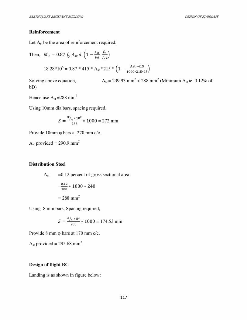
EARTHQUAKE RESISTANT BUILDING DESIGN OF STAIRCASE
117
Reinforcement
Let Ast be the area of reinforcement required.
Then, = . �� � � − � �
18.28*106 = 0.87 * 415 * Ast *215 * − A ∗∗ ∗
Solving above equation, Ast = 239.93 mm2 < 288 mm
2 (Minimum Ast ie. 0.12% of
bD)
Hence use Ast =288 mm2
Using 10mm dia bars, spacing required,
� = �⁄ ∗ ∗ = 272 mm
Provide 10mm φ bars at 270 mm c/c.
Ast provided = 290.9 mm2
Distribution Steel
Ast =0.12 percent of gross sectional area
=. ∗ ∗
= 288 mm2
Using 8 mm bars, Spacing required,
� = �⁄ ∗ ∗ = 174.53 mm
Provide 8 mm φ bars at 170 mm c/c.
Ast provided = 295.68 mm2
Design of flight BC
Landing is as shown in figure below:
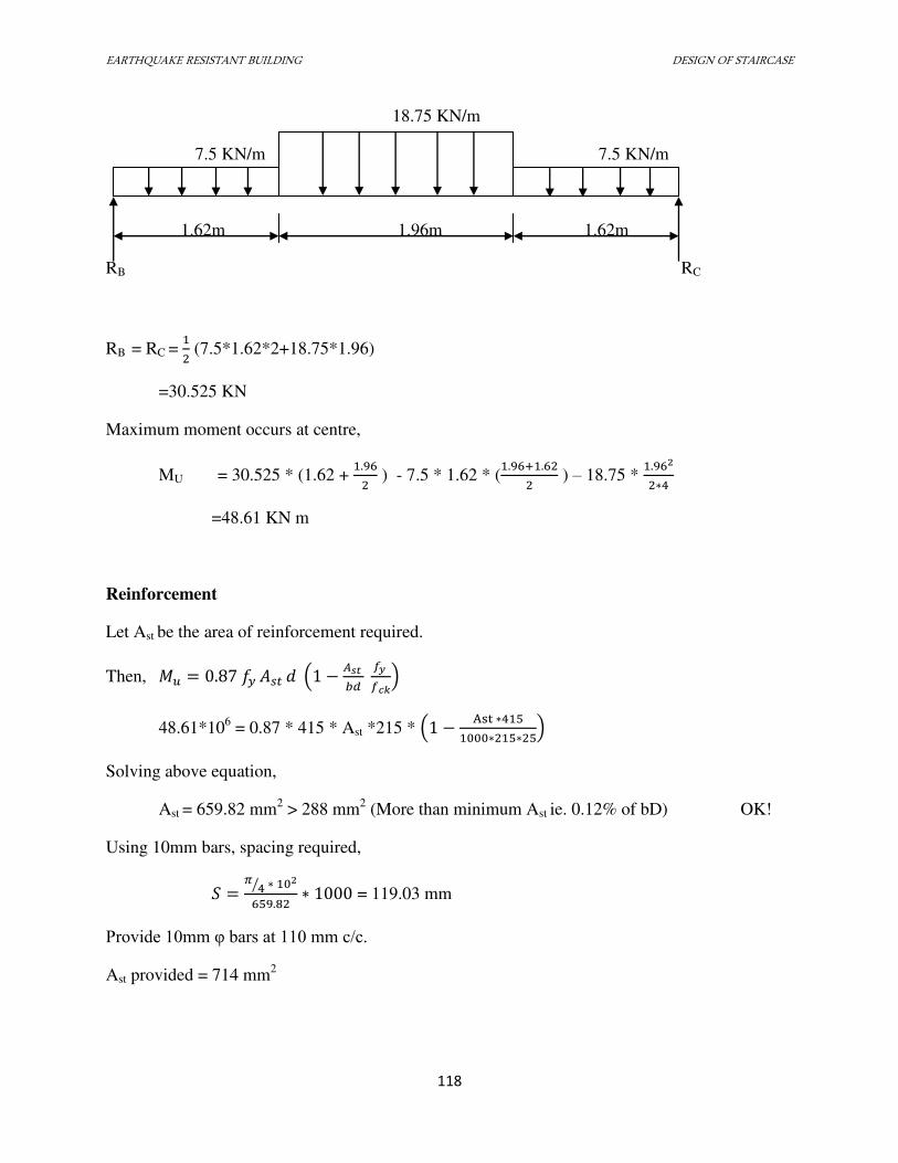
EARTHQUAKE RESISTANT BUILDING DESIGN OF STAIRCASE
118
18.75 KN/m
7.5 KN/m 7.5 KN/m
1.62m 1.96m 1.62m
RB RC
RB = RC = (7.5*1.62*2+18.75*1.96)
=30.525 KN
Maximum moment occurs at centre,
MU = 30.525 * (1.62 + .
) - 7.5 * 1.62 * (. + .
) – 18.75 * . ∗
=48.61 KN m
Reinforcement
Let Ast be the area of reinforcement required.
Then, = . �� � � − � �
48.61*106 = 0.87 * 415 * Ast *215 * − A ∗∗ ∗
Solving above equation,
Ast = 659.82 mm2 > 288 mm
2 (More than minimum Ast ie. 0.12% of bD) OK!
Using 10mm bars, spacing required,
� = �⁄ ∗ . ∗ = 119.03 mm
Provide 10mm φ bars at 110 mm c/c.
Ast provided = 714 mm2
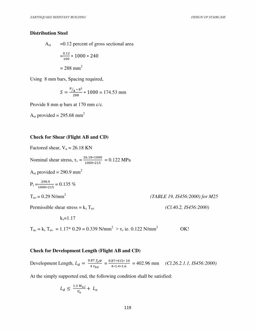
EARTHQUAKE RESISTANT BUILDING DESIGN OF STAIRCASE
119
Distribution Steel
Ast =0.12 percent of gross sectional area
=. ∗ ∗
= 288 mm2
Using 8 mm bars, Spacing required,
� = �⁄ ∗ ∗ = 174.53 mm
Provide 8 mm φ bars at 170 mm c/c.
Ast provided = 295.68 mm2
Check for Shear (Flight AB and CD)
Factored shear, Vu = 26.18 KN
Nominal shear stress, τv = . ∗∗ = 0.122 MPa
Ast provided = 290.9 mm2
Pt =. ∗ = 0.135 %
Τuv = 0.29 N/mm2 (TABLE 19, IS456:2000) for M25
Permissible shear stress = ks Τuv (Cl.40.2, IS456:2000)
ks=1.17
Τuc = ks Τuv = 1.17* 0.29 = 0.339 N/mm2 > τv ie. 0.122 N/mm
2 OK!
Check for Development Length (Flight AB and CD)
Development Length, = . �� � = . ∗ ∗ ∗ . ∗ . = 402.96 mm (Cl.26.2.1.1, IS456:2000)
At the simply supported end, the following condition shall be satisfied:
≤ . � ,� +
EARTHQUAKE RESISTANT BUILDING DESIGN OF STAIRCASE
120
And, , = . ��� � − . � Where, � = . ∗ ∗ .. ∗ ∗ = 11.67
, = . ∗ ∗ . ∗ − . ∗ . = 22.07 * 106 N-mm
� = .
= � �� �
= �� �� ��
Take greater. Ie. 215 mm.
≤ . ∗ . ∗ 6. ∗ + �� = 1310.91 mm
Hence, 409.96 mm < 1310.91 mm. OK!
Adopt Ld=420 mm.
Check for deflection (Flight AB and CD)
From the deflection criteria of serviceability requirements:
� = . �� (� , �� , � ) = 0.58 * 415 * . = 238.3 MPa
Modification factor for � , � = . % and � = . MPa is 1.82.
(Fig4, Cl.23.2.1, IS456:2000)
Thus,
� = ∗ � � � = ∗ . = . �� < �� OK!
Check for Shear (Flight BC)
Factored shear, Vu = 30.525 KN
Nominal shear stress, τv = . ∗∗ = 0.142 MPa
EARTHQUAKE RESISTANT BUILDING DESIGN OF STAIRCASE
121
Ast provided = 714 mm2
Pt = ∗ = 0.332 %
Τuv = 0.403 N/mm2 (TABLE 19, IS456:2000) for M25
Permissible shear stress = ks Τuv (Cl.40.2, IS456:2000)
ks=1.17
Τuc = ks Τuv = 1.17* 0.403 = 0.472 N/mm2 > τv ie. 0.142 N/mm
2 OK!
Check for Development Length (Flight BC)
Development Length, = . �� � = . ∗ ∗ ∗ . ∗ . = 402.96 mm (Cl.26.2.1.1, IS456:2000)
At the simply supported end, the following condition shall be satisfied:
≤ . � ,� +
And, , = . ��� � − . � Where, � = . ∗ ∗. ∗ ∗ = 28.64
, = . ∗ ∗ ∗ − . ∗ . = 52.35 * 106 N-mm
� = .
= � �� �
= �� �� ��
Take greater. Ie. 215 mm.
≤ . ∗ . ∗ 6. ∗ + �� = 2444.48 mm
Hence, 402.96 mm < 2444.48 mm. OK!
Adopt Ld=420 mm.
EARTHQUAKE RESISTANT BUILDING DESIGN OF STAIRCASE
122
Check for deflection (Flight BC)
From the deflection criteria of serviceability requirements:
� = . �� (� , �� , � ) = 0.58 * 415 * .
= 222.435 MPa
Modification factor for � , � = . % and � = . MPa is 1.58.
(Fig4, Cl.23.2.1, IS456:2000)
Thus,
� = ∗ � � � = ∗ . = . �� < �� OK!
EARTHQUAKE RESISTANT BUILDING DESIGN OF FOUNDATION
123
7.5 DESIGN OF FOUNDATION
INTRODUCTION
Foundation is a structural element that transfers loads from the building or individual to
the earth. If the loads are to be properly transmitted, foundation must be designed to prevent
excessive settlement or rotation, to minimized differential settlement and to provide adequate
sliding and overturning.
SELECTION OF FOUNDATION TYPE
The project site is assumed to be located at a site having soil bearing capacity medium.
The foundation has been designed for critical members or column carrying maximum axial
load. If the load transmitted by the column in the structure is too heavy or the allowable soil
pressure is too less or individual footings would cover more than 50% of the whole area, it
may be better to provide continuous footing under all the columns and walls. Such a footing is
called a Raft or Mat foundation.
Considering the above facts we have preferred Mat foundation for our project.
The choice of footing type must be done with comparative study of different design to
identify the most economical foundation. Following few factors can be considered:
1) Type of structure
2) Type of loads
3) Bearing capacity
4) Economy
EARTHQUAKE RESISTANT BUILDING DESIGN OF FOUNDATION
124
DESIGN OF MAT FOUNDATION
If the loads transmitted by the columns in a structure are so heavy or the allowable soil
bearing pressure so small that individual footing would cover more than about one half of the
area, it may be better to provide a continuous footing under all the columns and walls. Such a
footing is called a raft or mat foundation. The raft foundation is divided into series of
continuous strip. The shear and bending moment diagrams may be drawn using continuous
beam analysis or coefficients for each strip. The depth is selected to satisfy shear
requirements. The steel requirements will vary from strips. This method generally gives a
conservative design since the interaction of adjacent strips is neglected.
DESIGN CALCULATION FOR MAT FOUNDATION:
1. Required Data:
Case considered = 1.5(DL+LL) i.e. combination 2
Total factored vertical load = 100908.4 KN
Soil bearing capacity = 120 KN/m2
Area required =100908.4/1.5×120 = 560.602 m2
Provide mat of area = 32×20 = 640 m2
2. Calculation of Centre of Gravity of plan area:
Centre of mass = (13.78, 9.09)
Centre of geometry = (14.26, 9.275) from grid F1
Eccentricity along X-direction:
ex = 9.275-10 = -0.725 m
Eccentricity along Y-direction:
ey = 14.26-16 = -1.74 m
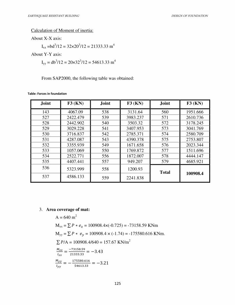
EARTHQUAKE RESISTANT BUILDING DESIGN OF FOUNDATION
125
Calculation of Moment of inertia:
About X-X axis:
Ixx =bd3/12 = 32×20
3/12 = 21333.33 m
4
About Y-Y axis:
Iyy = db3/12 = 20×32
3/12 = 54613.33 m
4
From SAP2000, the following table was obtained:
Table: Forces in foundation
Joint F3 (KN) Joint F3 (KN) Joint F3 (KN)
143 4067.09 538 3131.64 560 1951.666
527 2422.479 539 3983.237 571 2610.736
528 2442.902 540 3503.32 572 3178.245
529 3029.228 541 3407.953 573 3041.769
530 3716.837 542 2785.371 574 2580.709
531 4287.087 543 4390.378 575 2753.807
532 3355.939 549 1671.658 576 2023.344
533 1057.069 550 1769.872 577 1511.696
534 2522.771 556 1872.007 578 4444.147
535 4407.441 557 949.207 579 4685.921
536 5323.999 558 1200.93 Total 100908.4
537 4586.133 559 2241.838
3. Area coverage of mat:
A = 640 m2
Mxx = ∑ � ∗ = 100908.4×(-0.725) = -73158.59 KNm
Myy = ∑ � ∗ = 100908.4 × (-1.74) = -175580.616 KNm.
∑ �/A = 100908.4/640 = 157.67 KN/m2
�� = − .. = − .
�� = − . . = − .
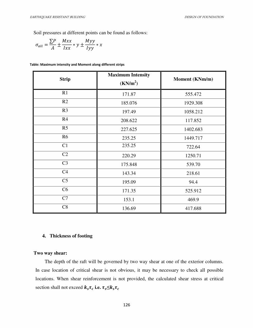
EARTHQUAKE RESISTANT BUILDING DESIGN OF FOUNDATION
126
Soil pressures at different points can be found as follows: � �� = ∑�� ± � ∗ ± � ∗
Table: Maximum intensity and Moment along different strips
Strip Maximum Intensity
(KN/m2) Moment (KNm/m)
R1 171.87 555.472
R2 185.076 1929.308
R3 197.49 1058.212
R4 208.622 117.852
R5 227.625 1402.683
R6 235.25 1449.717
C1 235.25 722.64
C2 220.29 1250.71
C3 175.848 539.70
C4 143.34 218.61
C5 195.09 94.4
C6 171.35 525.912
C7 153.1 469.9
C8 136.69 417.688
4. Thickness of footing
Two way shear:
The depth of the raft will be governed by two way shear at one of the exterior columns.
In case location of critical shear is not obvious, it may be necessary to check all possible
locations. When shear reinforcement is not provided, the calculated shear stress at critical
section shall not exceed ���� i.e. ��≤����
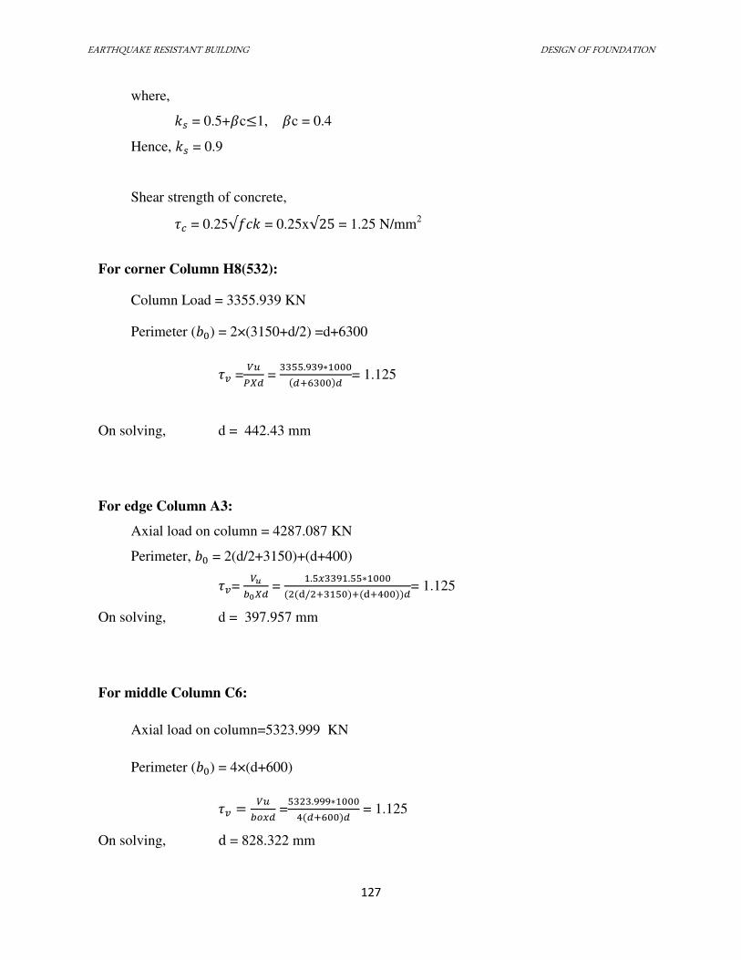
EARTHQUAKE RESISTANT BUILDING DESIGN OF FOUNDATION
127
where,
� = 0.5+�c≤1, �c = 0.4
Hence, � = 0.9
Shear strength of concrete,
� = 0.25√ � = 0.25x√ = 1.25 N/mm2
For corner Column H8(532):
Column Load = 3355.939 KN
Perimeter ( ) = 2×(3150+d/2) =d+6300
� =��� =
. ∗+ = 1.125
On solving, d = 442.43 mm
For edge Column A3:
Axial load on column = 4287.087 KN
Perimeter, = 2(d/2+3150)+(d+400)
� = ��� =
. . ∗d/ + + d+ = 1.125
On solving, d = 397.957 mm
For middle Column C6:
Axial load on column=5323.999 KN
Perimeter ( ) = 4×(d+600)
� = �� =. ∗+ = 1.125
On solving, d = 828.322 mm
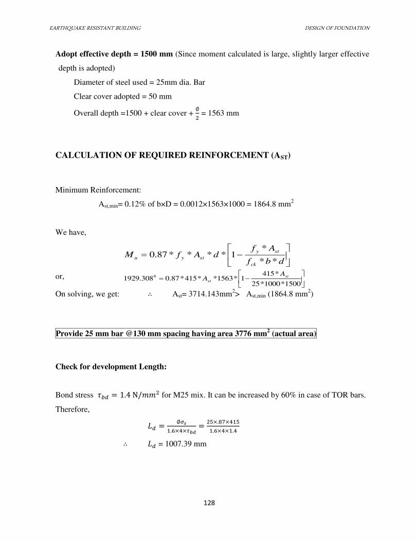
EARTHQUAKE RESISTANT BUILDING DESIGN OF FOUNDATION
128
Adopt effective depth = 1500 mm (Since moment calculated is large, slightly larger effective
depth is adopted)
Diameter of steel used = 25mm dia. Bar
Clear cover adopted = 50 mm
Overall depth =1500 + clear cover + ∅ = 1563 mm
CALCULATION OF REQUIRED REINFORCEMENT (AST)
Minimum Reinforcement:
Ast,min= 0.12% of b×D = 0.0012×1563×1000 = 1864.8 mm2
We have,
dbf
AfdAfM
ck
sty
styu**
*1****87.0
or,
1500*1000*25
*4151*1563**415*87.0308.1929 6 st
st
AA
On solving, we get: ∴ Ast= 3714.143mm
2> Ast,min (1864.8 mm
2)
Provide 25 mm bar @130 mm spacing having area 3776 mm2 (actual area)
Check for development Length:
Bond stress � = . N/�� for M25 mix. It can be increased by 60% in case of TOR bars.
Therefore,
= ∅��. × ×��� = 2 ×. ×. × × .
∴ = 1007.39 mm
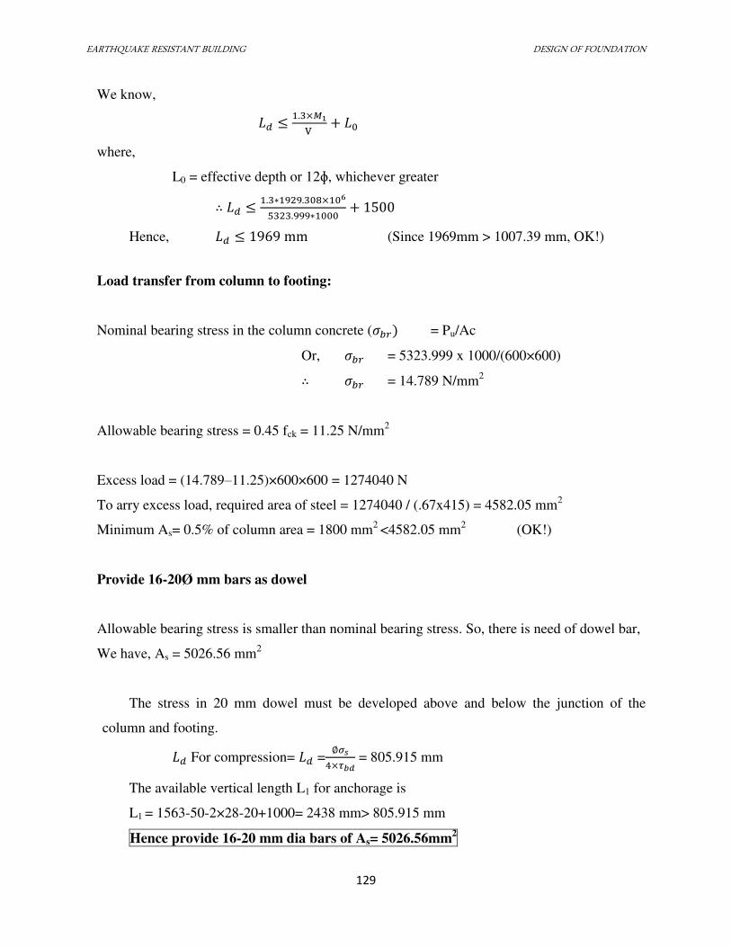
EARTHQUAKE RESISTANT BUILDING DESIGN OF FOUNDATION
129
We know,
≤ . ×�V +
where,
L0 = effective depth or 12ɸ, whichever greater
∴ ≤ . ∗ . × 6. ∗ +
Hence, ≤ 9 9 mm (Since 1969mm > 1007.39 mm, OK!)
Load transfer from column to footing:
Nominal bearing stress in the column concrete (� = Pu/Ac
Or, � = 5323.999 x 1000/(600×600)
∴ � = 14.789 N/mm2
Allowable bearing stress = 0.45 fck = 11.25 N/mm2
Excess load = (14.789–11.25)×600×600 = 1274040 N
To arry excess load, required area of steel = 1274040 / (.67x415) = 4582.05 mm2
Minimum As= 0.5% of column area = 1800 mm2
<4582.05 mm2
(OK!)
Provide 16-20Ø mm bars as dowel
Allowable bearing stress is smaller than nominal bearing stress. So, there is need of dowel bar,
We have, As = 5026.56 mm2
The stress in 20 mm dowel must be developed above and below the junction of the
column and footing.
For compression= =∅��×��� = 805.915 mm
The available vertical length L1 for anchorage is
L1 = 1563-50-2×28-20+1000= 2438 mm> 805.915 mm
Hence provide 16-20 mm dia bars of As= 5026.56mm2
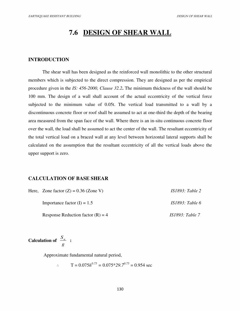
EARTHQUAKE RESISTANT BUILDING DESIGN OF SHEAR WALL
130
7.6 DESIGN OF SHEAR WALL
INTRODUCTION
The shear wall has been designed as the reinforced wall monolithic to the other structural
members which is subjected to the direct compression. They are designed as per the empirical
procedure given in the IS: 456-2000, Clause 32.2. The minimum thickness of the wall should be
100 mm. The design of a wall shall account of the actual eccentricity of the vertical force
subjected to the minimum value of 0.05t. The vertical load transmitted to a wall by a
discontinuous concrete floor or roof shall be assumed to act at one-third the depth of the bearing
area measured from the span face of the wall. Where there is an in-situ continuous concrete floor
over the wall, the load shall be assumed to act the center of the wall. The resultant eccentricity of
the total vertical load on a braced wall at any level between horizontal lateral supports shall be
calculated on the assumption that the resultant eccentricity of all the vertical loads above the
upper support is zero.
CALCULATION OF BASE SHEAR
Here, Zone factor (Z) = 0.36 (Zone V) IS1893: Table 2
Importance factor (I) = 1.5 IS1893: Table 6
Response Reduction factor (R) = 4 IS1893: Table 7
Calculation of g
Sa :
Approximate fundamental natural period,
∴ T = 0.075h0.75
= 0.075*29.70.75
= 0.954 sec
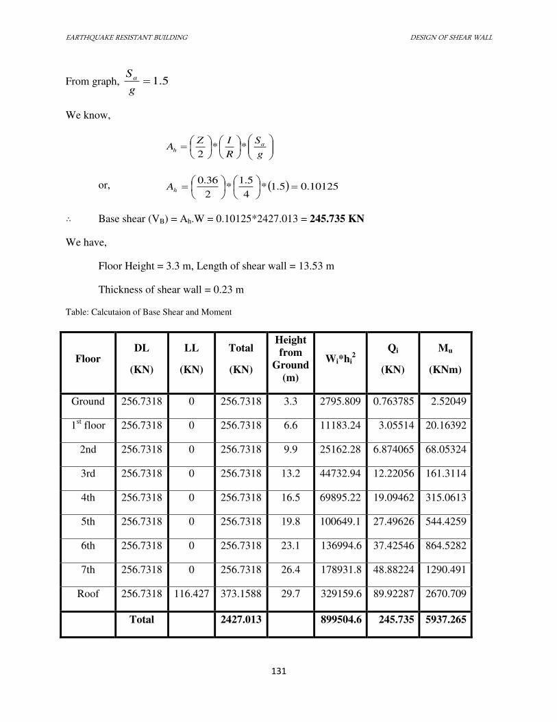
EARTHQUAKE RESISTANT BUILDING DESIGN OF SHEAR WALL
131
From graph, 5.1g
Sa
We know,
g
S
R
IZA a
h **2
or, 10125.05.1*4
5.1*
2
36.0
hA
∴ Base shear (VB) = Ah.W = 0.10125*2427.013 = 245.735 KN
We have,
Floor Height = 3.3 m, Length of shear wall = 13.53 m
Thickness of shear wall = 0.23 m
Table: Calcutaion of Base Shear and Moment
Floor DL
(KN)
LL
(KN)
Total
(KN)
Height
from
Ground
(m)
Wi*hi2
Qi
(KN)
Mu
(KNm)
Ground 256.7318 0 256.7318 3.3 2795.809 0.763785 2.52049
1st floor 256.7318 0 256.7318 6.6 11183.24 3.05514 20.16392
2nd 256.7318 0 256.7318 9.9 25162.28 6.874065 68.05324
3rd 256.7318 0 256.7318 13.2 44732.94 12.22056 161.3114
4th 256.7318 0 256.7318 16.5 69895.22 19.09462 315.0613
5th 256.7318 0 256.7318 19.8 100649.1 27.49626 544.4259
6th 256.7318 0 256.7318 23.1 136994.6 37.42546 864.5282
7th 256.7318 0 256.7318 26.4 178931.8 48.88224 1290.491
Roof 256.7318 116.427 373.1588 29.7 329159.6 89.92287 2670.709
Total
2427.013
899504.6 245.735 5937.265
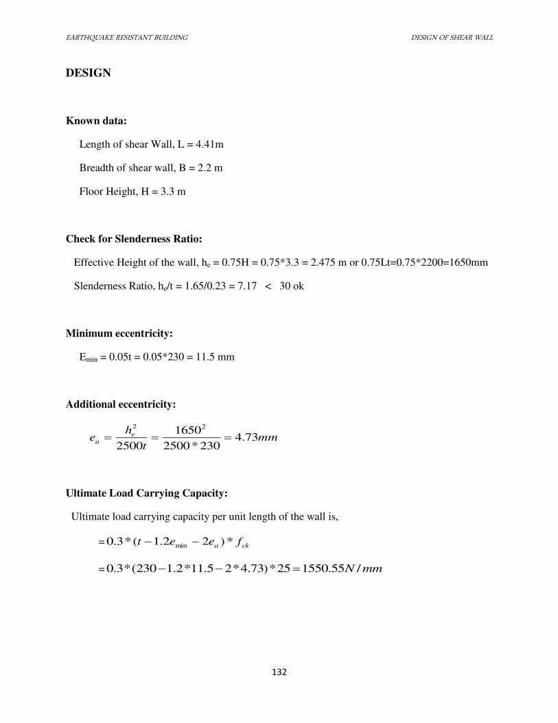
EARTHQUAKE RESISTANT BUILDING DESIGN OF SHEAR WALL
132
DESIGN
Known data:
Length of shear Wall, L = 4.41m
Breadth of shear wall, B = 2.2 m
Floor Height, H = 3.3 m
Check for Slenderness Ratio:
Effective Height of the wall, he = 0.75H = 0.75*3.3 = 2.475 m or 0.75Lt=0.75*2200=1650mm
Slenderness Ratio, he/t = 1.65/0.23 = 7.17 < 30 ok
Minimum eccentricity:
Emin = 0.05t = 0.05*230 = 11.5 mm
Additional eccentricity:
mmt
he e
a 73.4230*2500
1650
2500
22
Ultimate Load Carrying Capacity:
Ultimate load carrying capacity per unit length of the wall is,
= cka feet *)22.1(*3.0 min
= mmN /55.155025*)73.4*25.11*2.1230(*3.0
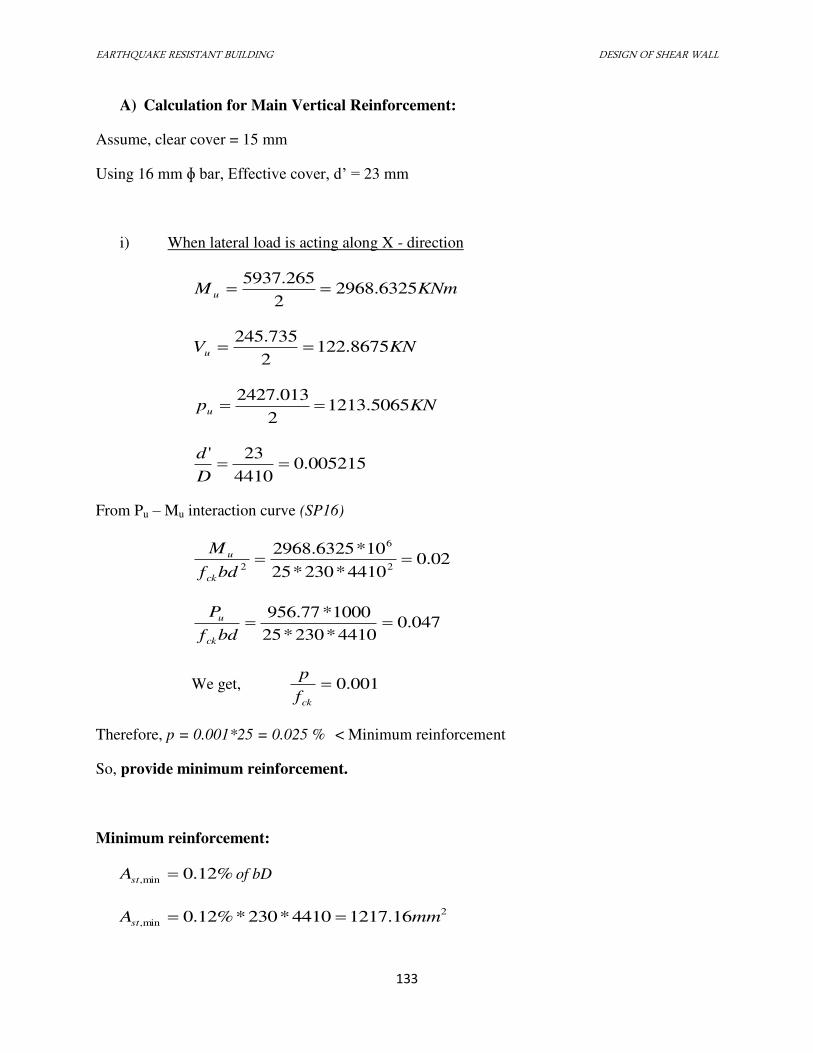
EARTHQUAKE RESISTANT BUILDING DESIGN OF SHEAR WALL
133
A) Calculation for Main Vertical Reinforcement:
Assume, clear cover = 15 mm
Using 16 mm ɸ bar, Effective cover, d’ = 23 mm
i) When lateral load is acting along X - direction
KNmM u 6325.29682
5937.265
KNVu 8675.1222
245.735
KNpu 5065.12132
2427.013
005215.04410
23'
D
d
From Pu – Mu interaction curve (SP16)
02.04410*230*25
10*6325.29682
6
2
bdf
M
ck
u
047.04410*230*25
1000*77.956
bdf
P
ck
u
We get, 001.0ckf
p
Therefore, p = 0.001*25 = 0.025 % < Minimum reinforcement
So, provide minimum reinforcement.
Minimum reinforcement:
%12.0min, stA of bD
2
min, 16.12174410*230*%12.0 mmAst
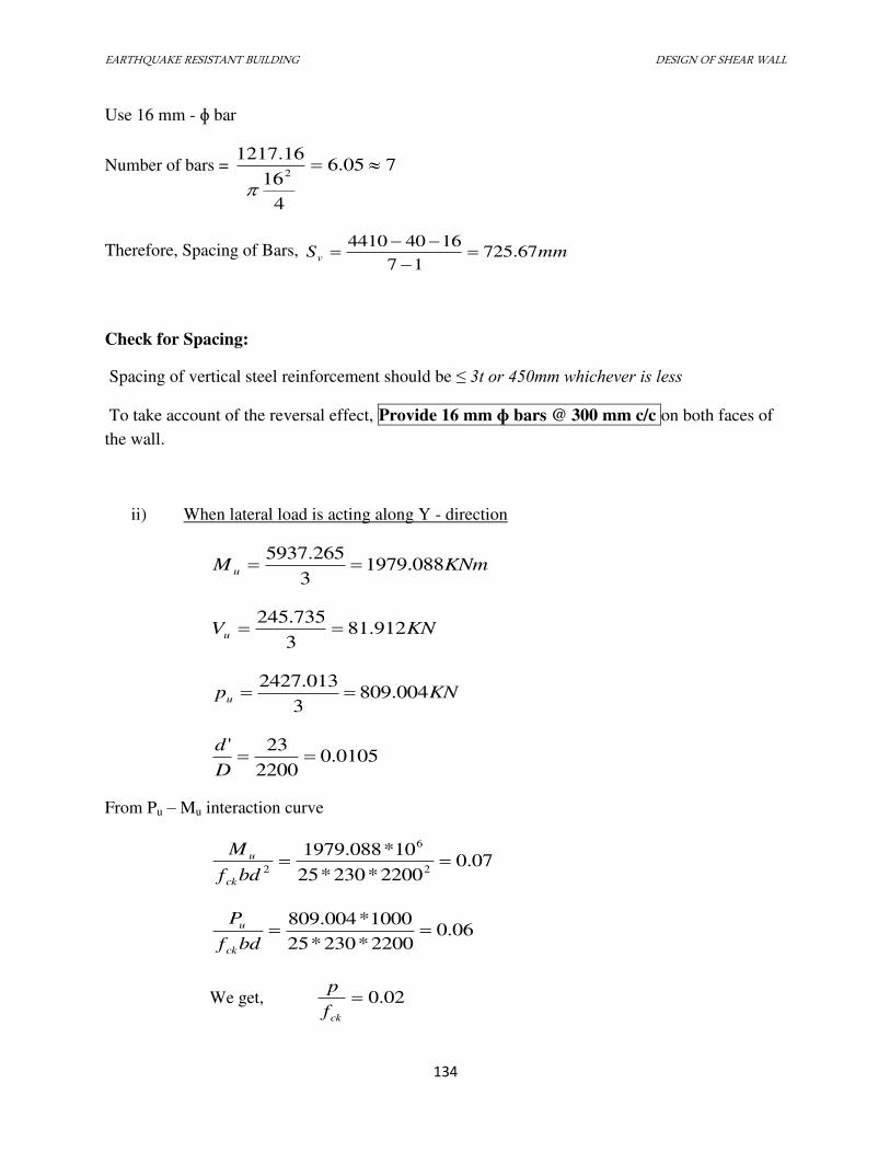
EARTHQUAKE RESISTANT BUILDING DESIGN OF SHEAR WALL
134
Use 16 mm - ɸ bar
Number of bars = 705.6
4
16
16.12172
Therefore, Spacing of Bars, mmSv 67.72517
16404410
Check for Spacing:
Spacing of vertical steel reinforcement should be ≤ 3t or 450mm whichever is less
To take account of the reversal effect, Provide 16 mm ɸ bars @ 300 mm c/c on both faces of
the wall.
ii) When lateral load is acting along Y - direction
KNmM u 088.19793
265.5937
KNVu 912.813
735.245
KNpu 004.8093
013.2427
0105.02200
23'
D
d
From Pu – Mu interaction curve
07.02200*230*25
10*088.19792
6
2
bdf
M
ck
u
06.02200*230*25
1000*004.809
bdf
P
ck
u
We get, 02.0ckf
p
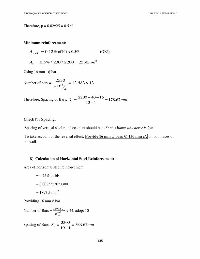
EARTHQUAKE RESISTANT BUILDING DESIGN OF SHEAR WALL
135
Therefore, p = 0.02*25 = 0.5 %
Minimum reinforcement:
%12.0min, stA of bD < 0.5% (OK!)
225302200*230*%5.0 mmAst
Using 16 mm - ɸ bar
Number of bars = 13583.12
416
25302
Therefore, Spacing of Bars, mmSv 67.178113
16402200
Check for Spacing:
Spacing of vertical steel reinforcement should be ≤ 3t or 450mm whichever is less
To take account of the reversal effect, Provide 16 mm ɸ bars @ 150 mm c/c on both faces of
the wall.
B) Calculation of Horizontal Steel Reinforcement:
Area of horizontal steel reinforcement
= 0.25% of bH
= 0.0025*230*3300
= 1897.5 mm2
Providing 16 mm ɸ bar
Number of Bars = .5� 64 = 9.44, adopt 10
Spacing of Bars, mmSv 67.366110
3300
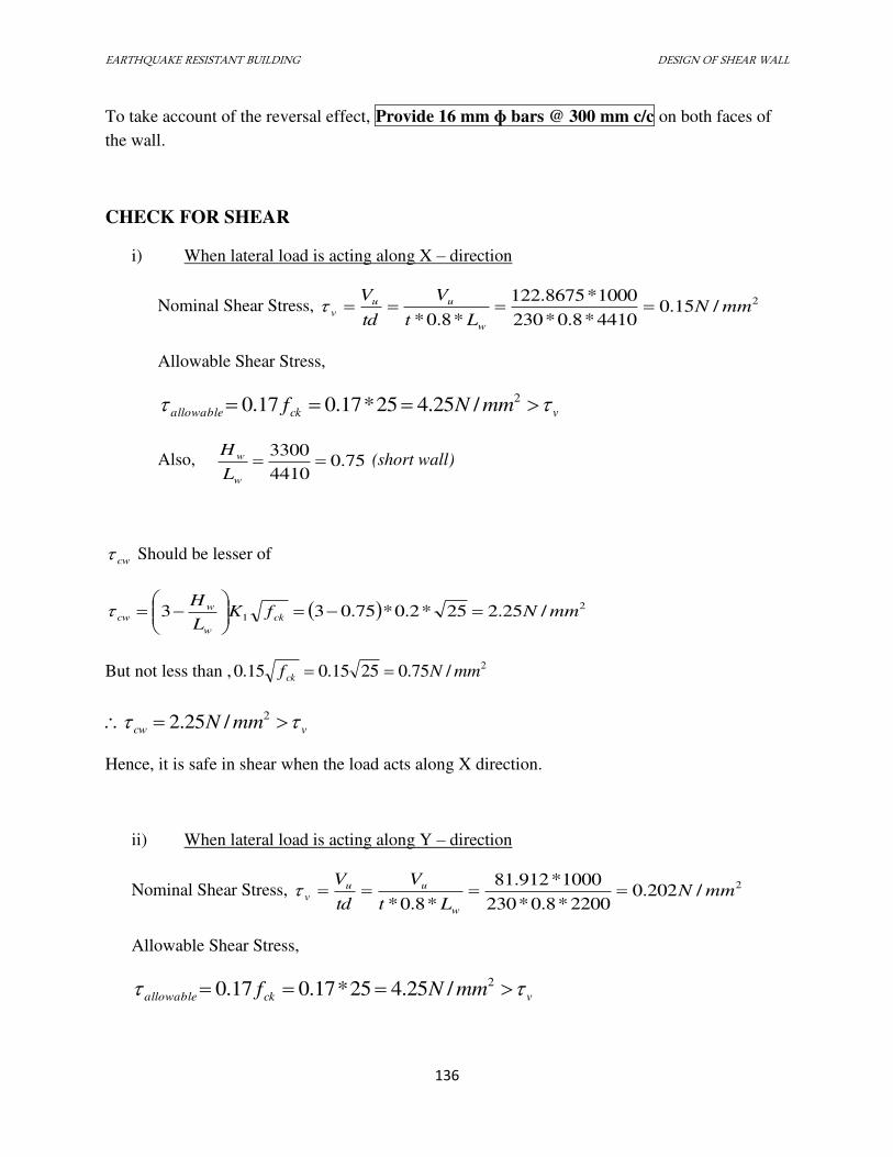
EARTHQUAKE RESISTANT BUILDING DESIGN OF SHEAR WALL
136
To take account of the reversal effect, Provide 16 mm ɸ bars @ 300 mm c/c on both faces of
the wall.
CHECK FOR SHEAR
i) When lateral load is acting along X – direction
Nominal Shear Stress, 2/15.04410*8.0*230
1000*8675.122
*8.0*mmN
Lt
V
td
V
w
uu
v
Allowable Shear Stress,
vckallowable mmNf 2/25.425*17.017.0
Also, 75.04410
3300
w
w
L
H (short wall)
cw Should be lesser of
2
1 /25.225*2.0*75.033 mmNfKL
Hck
w
w
cw
But not less than , 2/75.02515.015.0 mmNfck
vcw mmN 2/25.2
Hence, it is safe in shear when the load acts along X direction.
ii) When lateral load is acting along Y – direction
Nominal Shear Stress, 2/202.02200*8.0*230
1000*912.81
*8.0*mmN
Lt
V
td
V
w
uu
v
Allowable Shear Stress,
vckallowable mmNf 2/25.425*17.017.0
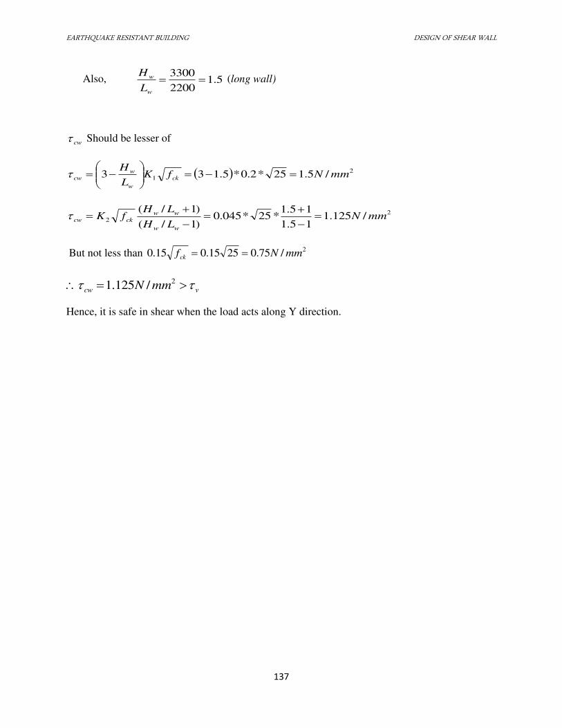
EARTHQUAKE RESISTANT BUILDING DESIGN OF SHEAR WALL
137
Also, 5.12200
3300
w
w
L
H (long wall)
cw Should be lesser of
2
1 /5.125*2.0*5.133 mmNfKL
Hck
w
w
cw
2
2 /125.115.1
15.1*25*045.0
)1/(
)1/(mmN
LH
LHfK
ww
ww
ckcw
But not less than 2/75.02515.015.0 mmNfck
vcw mmN 2/125.1
Hence, it is safe in shear when the load acts along Y direction.
EARTHQUAKE RESISTANT BUILDING DESIGN OF BASEMENT WALL
138
7.7 DESIGN OF BASEMENT WALL
7.7.1 INTRODUCTION
Basement wall is constructed to retain the earth and to prevent moisture from seeping into
the building. Since the basement wall is supported by the mat foundation, the stability is ensured
and the design of the basement wall is limited to the safe design of vertical stem.
Basement walls are exterior walls of underground structures (tunnels and other earth
sheltered buildings), or retaining walls must resist lateral earth pressure as well as additional
pressure due to other type of loading. Basement walls carry lateral earth pressure generally as
vertical slabs supported by floor framing at the basement level and upper floor level. The axial
forces in the floor structures are , in turn, either resisted by shear walls or balanced by the lateral
earth pressure coming from the opposite side of the building.
Although basement walls act as vertical slabs supported by the horizontal floor framing ,
keep in mind that during the early construction stage when the upper floor has not yet been built
the wall may have to be designed as a cantilever.
7.7.2 DESIGN OF VERTICAL STEM
The basement wall is designed as the cantilever wall with the fixity provided by the
mat foundation.
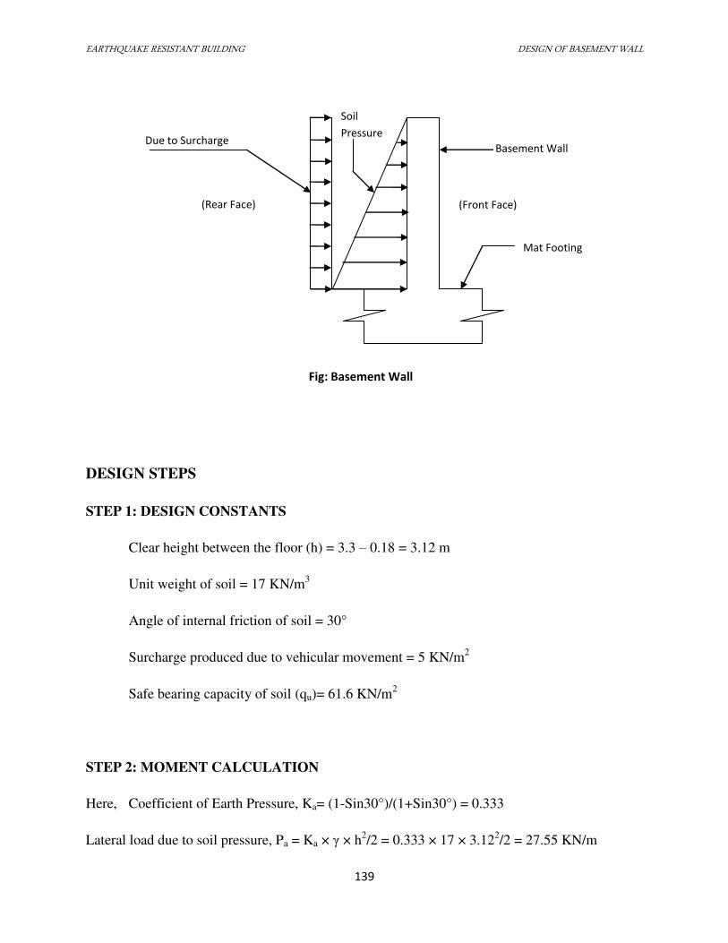
EARTHQUAKE RESISTANT BUILDING DESIGN OF BASEMENT WALL
139
DESIGN STEPS
STEP 1: DESIGN CONSTANTS
Clear height between the floor (h) = 3.3 – 0.18 = 3.12 m
Unit weight of soil = 17 KN/m3
Angle of internal friction of soil = 30°
Surcharge produced due to vehicular movement = 5 KN/m2
Safe bearing capacity of soil (qu)= 61.6 KN/m2
STEP 2: MOMENT CALCULATION
Here, Coefficient of Earth Pressure, Ka= (1-Sin30°)/(1+Sin30°) = 0.333
Lateral load due to soil pressure, Pa = Ka × γ × h2/2 = 0.333 × 17 × 3.12
2/2 = 27.55 KN/m
Due to Surcharge
(Rear Face)
Soil
Pressure
Basement Wall
(Front Face)
Mat Footing
Fig: Basement Wall
EARTHQUAKE RESISTANT BUILDING DESIGN OF BASEMENT WALL
140
Lateral load due to surcharge load, Ps = Ka × Ws × h = 0.333 × 5 × 3.12 = 5.1948 KN/m
Characteristic bending moment at the base of wall, since weight of wall gives insignificant
moment, this can be neglected.
Mc = Pa × h/3 + Ps × h/2 = 36.756 KNm
Design moment = 1.5 × Mc = 55.134 KNm
STEP 3: APPROXIMATE DESIGN OF SECTION
According to IS 456 Cl 32.3.4, approximate design of section can be done.
Let effective depth of wall = d
We know,
BM = 0.136fck bd2 = 55.134
or, 55.134 × 106 = 0.136 × 25 × 1000 × d
2 ∴ d = 127.34 mm
Let the clear cover be 25 mm.
Provide 20 mm dia bars. ∴ Overall depth of wall, D = 127.34 + 50 + 10 = 187.34 mm
Adopt, D = 200 mm
So, d = 200-50-10 = 140 mm
STEP 4: CALCULATION OF MAIN STEEL REINFORCEMENT
Ast == 0.002Dh = 0.002 × 200 × 3120 = 1248 mm2
EARTHQUAKE RESISTANT BUILDING DESIGN OF BASEMENT WALL
141
We have,
Minimum Ast = 0.0012 ×bd = 240 mm2 IS 456 Cl 32.5a
Maximum diameter of bar = D/8 = 25 mm IS 456 Cl 26.5.2.2
Provide 20 mm dia bar.
Here, spacing of bar, S is given by:
S = 3.14 ×20×20×1000 / (4×1287.025) = 244.097 mm ∴ S= 200 mm
Provide 20 mm bar at 200 mm c/c ∴ Provided Ast = 314.16×1000/200 = 1570.79 mm2 ∴ pt = 1570.79 ×100 / (1000×200) = 0.785%
But,
Maximum spacing = 3d = 420 mm or 450mm ie 420 mm IS 456 Cl 32.5b
Provide nominal vertical reinforcement 8mm @ 300mm c/c
STEP 5: CHECK FOR SHEAR
According to IS 456 Cl 31.6.2.2, the critical section for shear strength is taken at a
distance d from the face of the support. Thus, critical section is at d= 0.14m from the top of the
mat foundation i.e at 3.12 – 0.14 = 2.98m below the top edge of the wall.
Shear force at critical section, Vu is given by:
Vu = 1.5 × (Ka × Ws × Z + Ka × γ × Z2 /2 )
= 1.5 × (0.33 × 5 × 2.98 + 0.33 × 17 ×2.98 × 2.98/2) = 45.14 KN
Nominal shear stress τu = Vu/bd = 0.322 N/mm2
EARTHQUAKE RESISTANT BUILDING DESIGN OF BASEMENT WALL
142
Permissible shear stress, τc = 0.5798 N/mm2 IS 456: Table 19
Since τc>τu, the designed section is safe in shear.
STEP 6: CHECK FOR DEFLECTION
Deflection criteria was followed according to IS 456 Cl 23.2a.
We have,
Leff= 3.12 + 0.14 = 3.26m
Allowable deflection = Leff/250 = 13.04mm
Actual deflection = Ps ∗leff
4
8EI+
Ps ∗leff4
30EI = 10.62 mm
Since actual deflection < allowable deflection, the design is safe according to deflection criteria.
STEP 7: CALCULATION OF HORIZONTAL REINFORCEMENT STEEL BAR
Area of horizontal reinforcement = 0.002Dh = 0.002 × 200 × 3120 = 1248 mm2
As the temperature changes occurs at the front face of the basement wall, 2/3 of
horizontal reinforcement is provided at the front face and 1.3 of horizontal reinforcement is
provided at the inner face.
a) Front face horizontal reinforcement steel = 2/3 × 1248 = 832 mm2
Providing 10 mm dia bar, number of bars required (N) = 832/ (3.14 × 10²/ 4 ) = 11 nos
Spacing = (h – clear cover at both sides – dia) / ( N-1 ) IS 456: Cl 32.5d
or, � =3120−50−10
10= 306 ��
∴ Provide 10 mm dia bar at 300 mm c/c
EARTHQUAKE RESISTANT BUILDING DESIGN OF BASEMENT WALL
143
b) Inner face horizontal reinforcement steel = 1/3 × 1248 = 416 mm2
Provide 8 mm dia bars. ∴ No of bar required ( N) = 416 / ( 3.14 /4 × 82) = 9
Spacing = (h – clear cover at both sides – dia) / ( N-1 ) IS 456: Cl 32.5d
or, � =3120−50−8
10= 382 ��
∴ Provide 8 mm dia bar at 350 mm c/c
But, maximum spacing = 3d = 3 × 140 = 420 mm or 450 mm
Hence, spacing provided for horizontal steel is OK.
EARTHQUAKE RESISTANT BUILDING DETAILING OF STRUCTURAL ELEMENT
143
DETAILING OF STRUCTURAL ELEMENT
8.1 INTRODUCTION
Detailing refers primarily to the determination of the number, size, layout and
location of reinforcement, given the element dimensions and areas of steel required. While
certain details such as lap and development lengths, hook requirements, cut- off points etc. are
covered by the code, the logic in many situations has to be developed individually by the
designer on the basis of sound engineering judgments. It is useless if the design calculations are
represented by a set of poorly detailed drawing.
8.2 REQUIREMENTS OF A GOOD DETAILING
The following are the requirements of a good detailing:
1. Special attention is given at knee joints of corners joints under opening and closing loads.
2. The ductile detailing is the major part to improve for improving seismic resistance.
3. To improve the seismic performance of the joint:
Provide full anchorage to beam bars in column.
Provide confinements at the joint also.
Put beam bars inside the column bar.
Make extra care during concreting to project from honeycomb.
4. Reinforcement detailing should be simple for fabrication and placing.
5. Cracks widths must be within acceptable limits under service conditions. This is achieved
by limiting the spacing of reinforcement and minimum amount of reinforcement.
6. There should be sufficient space for concrete to be properly poured and compacted that is
achieved by minimum spacing between bars and thus avoiding congestion of
reinforcement.
7. The detailing should be such that internal forces are safely transferred from one member
to another and from reinforcement to concrete.

EARTHQUAKE RESISTANT BUILDING DETAILING OF STRUCTURAL ELEMENT
144
8. Detailing of member as per code IS 13920-1993 considering the earthquake load and
concentrated loads uniformly distribute loads, uniformly varying loads, random loads,
internal load and dynamic force.
EARTHQUAKE RESISTANT BUILDING RECOMMENDATIONS
145
RECOMMENDATIONS
Design and analysis are two important tasks for the successfulness of the project. Each
part should be done with great care and wisely to minimize the error.
Manual calculation is the initial job and it is with the reference to basic design
principle and various codes. But it is difficult for multi-storied building hence the use of
computer aided design and analysis is to be used. SAP 2000 version 15 and AutoCAD provide
almost accuracy and time saving in the analysis of the structure.
During our project, there were certain limitations and constraints which are
enumerated here in along with appropriate recommendations:
1. Manual calculation should be done and compared with the results obtained from
the SAP 2000 version 15 results to check the accuracy of the analysis.
2. All the work should be done under the constant supervision of qualified
engineers.
3. All the size and standards should be adopted as prescribed in the design.
EARTHQUAKE RESISTANT BUILDING BIBLIOGRAPHY
146
BIBLIOGRAPHY
REFERENCE BOOKS:
Reinforced Concrete Limit State Design - Jain, A. K.
Reinforced Concrete Design - Sinha, S. N.
Limit State Design of Reinforced Concrete- Varghese, P.C.
Reinforced Concrete Design- Pillai, S. Unnikrishna & Menon, Devdas
Earthquake Resistant Design of Structures- Agarwal, Pankaj & Shrikhande,
Manish
Dynamics Of Structures- Anil K. Chopra
REFERENCE CODES:
IS 456 : 2000 Code of Practice for Plain and Reinforced Concrete
IS 875 : 1987 Code of Practice for Design Load for Building and
o Structures (Part I – Dead Loads; Part II – Imposed
Loads)
IS 1893(Part I):2002 Criteria for Earthquake Resistant Design of Structures
IS 4326 : 1993 Earthquake Resistant Design and Construction of Buildings
o Code of Practice
IS 13920 : 1993 Ductile Detailing of Reinforced Concrete Structures
o Subjected to Seismic Forces – Code of Practice
SP 16 Design Aids for Reinforced Concrete to IS 456:1978
SP 34 Handbook of Concrete Reinforcement And Detailing
Related Documents