In electrcty terms, earthng s connectng a conductve element to the ground va a conductve path. Protectve Earthng Protectve earhng (R A ) s earthng of metal parts -that do not carry voltage under normal operaton but may carry voltage due to a fault- n order to protect people or other lvng thngs aganst hazardous touch or step voltage. In a low resstance protectve earthng, a fault voltage s fed through the faulty crcut durng the fault, therefore enablng the breakers tonstantly break the crcut and therefore cut the energy on the faulty crcut. Operatonal and Functonal Earthng Operatonal Earthng (R B ) s the earthng of the voltage of actve parts of operatonal devces of an electrcal faclty that are under voltage aganst earth n attempt to keep at a specfic value (e.g. star pont earthng) Functonal Earthng (R ) s earthng of a communcaton faclty or an operatonal devce n order to resume the desred functon. F Earthng Systems As a crucal safety element n electrcal networks, earthng nfrastructures have ganed ther long-deserved mportance n the last years. Consequently, applcaton crtera have mproved wth wdenng dversty of equpments. Havng keen expertse n the applcaton field, our company strves to serve beyond sales n provdng every sort of equpment. In a sector that requres quck and correct delvery, MTK s able to meet the requrements of the customers wth a wde product range of copper and galvanzed conductors and related connecton elements n a promt fashon thanks to ts dlgence n stock and transportaton. Earthng Systems

Welcome message from author
This document is posted to help you gain knowledge. Please leave a comment to let me know what you think about it! Share it to your friends and learn new things together.
Transcript

In electr�c�ty terms, earth�ng �s connect�ng a conduct�ve element to the ground v�a a conduct�ve path.
Protect�ve Earth�ng
Protect�ve earh�ng (RA) �s earth�ng of
metal parts -that do not carry voltage under normal operat�on but may carry voltage due to a fault- �n order to protect people or other l�v�ng th�ngs aga�nst hazardous touch or step voltage.
In a low res�stance protect�ve earth�ng, a fault voltage �s fed through the faulty c�rcu�t dur�ng the fault, therefore enabl�ng the breakers to �nstantly break the c�rcu�t and therefore cut the energy on the faulty c�rcu�t.
Operat�onal and Funct�onal Earth�ng
Operat�onal Earth�ng (RB) �s the earth�ng of the voltage of act�ve parts of operat�onal dev�ces of an electr�cal fac�l�ty that are under voltage
aga�nst earth �n attempt to keep at a spec�fic value (e.g. star po�nt earth�ng)
Funct�onal Earth�ng (R ) �s earth�ng of a commun�cat�on fac�l�ty or an operat�onal dev�ce �n order to resume the des�red funct�on.F
Earth�ng Systems
As a cruc�al safety element �n electr�cal networks, earth�ng �nfrastructures have ga�ned the�r long-deserved �mportance �n the last years. Consequently, appl�cat�on cr�ter�a have �mproved w�th w�den�ng d�vers�ty of equ�pments. Hav�ng keen expert�se �n the appl�cat�on field, our company str�ves to serve beyond sales �n prov�d�ng every sort of equ�pment. In a sector that requ�res qu�ck and correct del�very, MTK �s able to meet the requ�rements of the customers w�th a w�de product range of copper and galvan�zed conductors and related connect�on elements �n a promt fash�on thanks to �ts d�l�gence �n stock and transportat�on.
Earth�ng Systems
Foundat�on Earth�ng
In terms of �nstallat�on and operat�on of electr�cal systems, the pr�mary purpose of earth�ng �s to protect humans and an�mals from hazardous voltages. In add�t�on, earth�ng also prevents potent�al surges and secondary �mpacts. In Turkey, �nstallat�on and operat�on of earth�ng fac�l�t�es are regulated �n �ssue 24500 of the Offic�al Gazette (dtd. Aug.8, 2001) where all techn�cal deta�ls for foundat�on earth�ng have been covered. In attempt to summar�ze the s�gn�ficance of these terms, extra care must be exerc�sed at all t�mes to acknowledge and pract�ce them.
• Foundat�on earth�ng electrode should be made as a closed r�ng and be placed at the external walls or foundat�on platform of thebu�ld�ng.
• Foundat�on earth�ng electrode should be thoroughly covered �n concrete and placed �n a way that �t �s surrounded w�th 5 cm of concreteat all �ts s�des once the foundat�on concrete has been la�d. F�nal po�nts must extrude from the foundat�on.
• The placement of the earth�ng electrode �ns�de the concrete must be fixed w�th supports at appropr�ate d�stances, such as w�th 30cmlong rods �n 2m �ntervals.
• In re�nforced foundat�ons (such as steel mesh), earth�ng electrode must be placed on the lowermost mesh and fixed to the steel mesh�n 2m �ntervals.
• In foundat�on earth�ng, 30x3.5mm galvan�zed steel str�ps or 10mm d�ameter round galvan�zed steel rods must be used.
• In bu�ld�ngs w�th large base foundat�ons, the area surround�ng the foundat�on earth�ng must be �nstalled �n at most 20x20m sect�ons.
• Connect�on jo�nts of the foundat�on earth�ng must be at least 1,5 meter �n length �nto the bu�ld�ng and must be protected aga�nstcorros�on at the po�nts of ex�t.
• Potent�al balanc�ng bars must be used at all t�mes.
• For ma�n potent�al balanc�ng, connect�on elements or jo�nts must be connected to the potent�al balanc�ng bar and placed near thema�n panel of the bu�ld�ng.
• For conven�ent separat�on of earth conductors dur�ng res�stance measurements, related setup must be placed �n a reachable manner.
• Separat�on assembly of the earth conductor must have h�gh mechan�cal durab�l�ty.
• Equ�pments to be used �n foundat�on earth�ng must be chosen �n order to prevent corros�on.
• Mater�als used �n the rod jo�nts must be of the same mechan�cal durab�l�ty.
• Foundat�on earth�ng also serves as earth�ng �n l�ghtn�ng protect�on systems. Therefore, a number of ex�ts are left open us�ng e�thercables w�th at least 50 mm2 (NYY) sect�on or steel str�ps.
• Foundat�on earth�ng must str�ctly comply w�th the perta�n�ng deta�ls �n the earth�ng project wh�ch �s a prerequ�s�te for the approval ofthe electr�cal project of the bu�ld�ng.
Earth�ng Systems
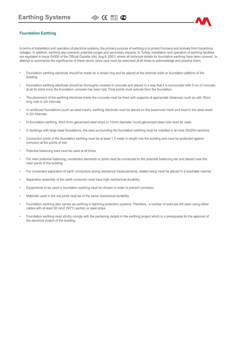
D�ffus�on Res�stance Values for Earth�ng �n So�l W�th a Res�st�v�ty of qE=100 Ohm.m
Earth�ng electrode
30x3 mm Str�p d=20 mm Rod
l 10 m 25 m 50 m 100 m 1 m 1.5 m 3.5 m 7 m
R 30.25E
13.27 7.07 3.76 84.4 60.55 29.80 16.48
Earth�ng electrode
R�ng sect�on (c�rcular) 95mm² Cu d=12.7 mm Foundat�on 30x3 mm Str�p+Iron Armatures+ Concrete
D 20 m 50 m 100 m 150 m 20 m 50 m 100 m 150 m
R 4.67E
2.05 1.1 0.76 3.18 1.27 0.64 0.42
Calculat�on of Earth Res�stance Accord�ng to So�l Types
Foundat�on Earth�ng electrode
2qER =
E P�.D
Earth�ng rod
qER = xln
E 2P�.L
4.L
d
Earth�ng str�p
qER = Ln
E P�
2L
d
Earth�ng mesh
qER = ln
E 2D
qE
L
Earth�ng plate
R = ( 0.5+E 2D
q dE
4.P�.H)
Earth�ng r�ng
R =E
qE ln
2D.P�
2.P�.D
d
qE: So�l res�st�v�ty (Ohm.m)
I: Length of earth�ng electrode (m)
d: If c�rcular, d�ameter (mm) of earth�ng electrode If rectangular, half the th�ckness (short s�de) of earth�ng electrode (m)
D: D�ameter of a c�rcle equal to the area covered by the earth�ng electrode (m).
A: Area covered by the earth�ng electrode (m 2)
H: Bury�ng depth measured at center.
So�l Res�st�v�ty Values
Res�st�v�ty of so�l depends on the type, dens�ty, mo�sture and temperature. Although the follow�ng table can be used for d�fferent types
of so�l, �t's more appropr�ate to use values determ�ned by measurements made on s�te.
So�l Res�st�v�ty �n AC Current
Type of So�l So�l Res�st�v�ty (Ohm.m)
Bataklık / Swamp 5 - 40
Çamur, K�l / Clay 20 - 200
Kum / Sand 200 - 2500
Çakıl / Gravel 2000 - 3000
Earth�ng Systems
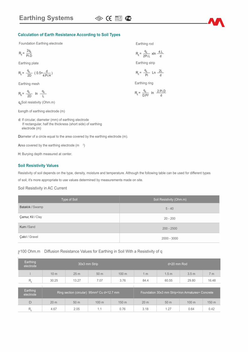
Part No. Mater�alConductor
D�ameter (mm²)Strand�ng
No. (Ø)Nom�nal
D�ameter (Ø)We�ght (m)
ET.C.SW.10 Cu 10 7x1.35 4.20 mm 0,09
ET.C.SW.16 Cu 16 7x1.70 5.10 mm 0,14
ET.C.SW.25 Cu 25 7x2.14 6.42 mm 0,22
ET.C.SW.35 Cu 35 7x2.52 7.56 mm 0,31
ET.C.SW.50 Cu 50 7x3.00 8.90 mm 0,44
ET.C.SW.70 Cu 70 19x2.14 10.70 mm 0,62
ET.C.SW.95 Cu 95 19x2.52 12.60 mm 0,84
ET.C.SW.120 Cu 120 19x2.80 14.20 mm 1,07
ET.C.SW.150 Cu 150 37x2.25 15.75 mm 1,34
ET.C.SW.185 Cu 185 37x2.52 17.64 mm 1,65
ET.C.SW.240 Cu 240 61x2.25 20.25 mm 2,14
Bakır �letkenler EN 60228 Class 2’ye göre üret�lmekted�r.Copper conductors are manufactured accord�ng to EN 60228 Class 2Cu: Bakır / Copper
Part No. Mater�alConductor
D�ameter (mm²)Nom�nal
D�ameter (Ø)We�ght (m)
ET.C.MW.1.5 Cu 1.5 1.38 mm 0,01
ET.C.MW.2.5 Cu 2.5 1.78 mm 0,02
ET.C.MW.4 Cu 4 2.30 mm 0,04
ET.C.MW.6 Cu 6 2.80 mm 0,05
ET.C.MW.10 Cu 10 3.60 mm 0,09
ET.C.MW.16 Cu 16 4.50 mm 0,14
ET.C.MW.25 Cu 25 5.60 mm 0,22
ET.C.MW.35 Cu 35 6.00 mm 0,31
ET.C.MW.50 Cu 50 8.00 mm 0,44
ET.C.MW.70 Cu 70 9.50 mm 0,63
ET.A.MW.50 Al 50 8.00 mm 0,13
ET.A.MW.70 Al 70 9.50 mm 0,19
Bakır �letkenler EN 13601 - EN 13602’ye göre üret�lmekted�r.Copper conductors are manufactured accord�ng to EN 13601 - EN 13602.Alüm�nyum �letkenler EN 755-5’e göre üret�lmekted�r.Alum�num conductors are manufactured accord�ng to EN 755-5.Cu: Bakır / CopperAl: Alüm�nyum / Alum�n�um
Örgülü Bakır İletkenlerBare Stranded Copper Cable
Mono İletkenlerBare Sol�d C�rcular
Galvan�z Mono İletkenlerHot D�p Galvan�zed Mono W�re
Part No. Mater�alConductor D�ameter
StandardCo�l S�ze
We�ght (m)
ET.FD.MW.8 StZn 8.0 mm 120 m ~ 0,42
ET.FD.MW.10 StZn 10.0 mm 80 m ~ 0,64
Galvan�z �letkenler EN 62561-2’e göre üret�lmekted�r.Galvan�zed conductors are manufactured accord�ng to EN 62561-2.St: Çel�k / SteelZn:Ç�nko / Z�nc
Earth�ng Systems
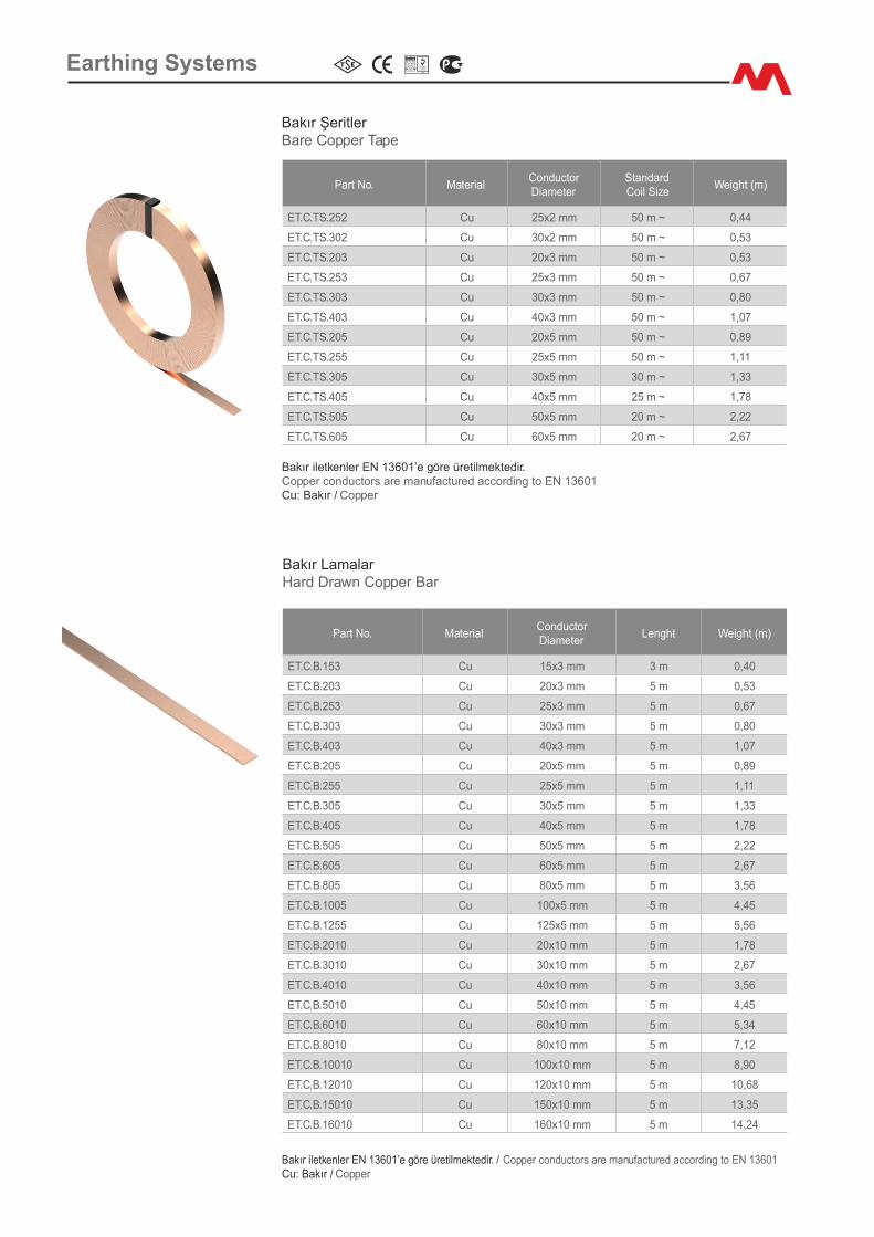
Bakır Şer�tlerBare Copper Tape
Bakır �letkenler EN 13601’e göre üret�lmekted�r.Copper conductors are manufactured accord�ng to EN 13601Cu: Bakır / Copper
Part No. Mater�alConductor D�ameter
StandardCo�l S�ze
We�ght (m)
ET.C.TS.252 Cu 25x2 mm 50 m ~ 0,44
ET.C.TS.302 Cu 30x2 mm 50 m ~ 0,53
ET.C.TS.203 Cu 20x3 mm 50 m ~ 0,53
ET.C.TS.253 Cu 25x3 mm 50 m ~ 0,67
ET.C.TS.303 Cu 30x3 mm 50 m ~ 0,80
ET.C.TS.403 Cu 40x3 mm 50 m ~ 1,07
ET.C.TS.205 Cu 20x5 mm 50 m ~ 0,89
ET.C.TS.255 Cu 25x5 mm 50 m ~ 1,11
ET.C.TS.305 Cu 30x5 mm 30 m ~ 1,33
ET.C.TS.405 Cu 40x5 mm 25 m ~ 1,78
ET.C.TS.505 Cu 50x5 mm 20 m ~ 2,22
ET.C.TS.605 Cu 60x5 mm 20 m ~ 2,67
Bakır LamalarHard Drawn Copper Bar
Bakır �letkenler EN 13601’e göre üret�lmekted�r. / Copper conductors are manufactured accord�ng to EN 13601Cu: Bakır / Copper
Part No. Mater�alConductorD�ameter
Lenght We�ght (m)
ET.C.B.153 Cu 15x3 mm 3 m 0,40
ET.C.B.203 Cu 20x3 mm 5 m 0,53
ET.C.B.253 Cu 25x3 mm 5 m 0,67
ET.C.B.303 Cu 30x3 mm 5 m 0,80
ET.C.B.403 Cu 40x3 mm 5 m 1,07
ET.C.B.205 Cu 20x5 mm 5 m 0,89
ET.C.B.255 Cu 25x5 mm 5 m 1,11
ET.C.B.305 Cu 30x5 mm 5 m 1,33
ET.C.B.405 Cu 40x5 mm 5 m 1,78
ET.C.B.505 Cu 50x5 mm 5 m 2,22
ET.C.B.605 Cu 60x5 mm 5 m 2,67
ET.C.B.805 Cu 80x5 mm 5 m 3,56
ET.C.B.1005 Cu 100x5 mm 5 m 4,45
ET.C.B.1255 Cu 125x5 mm 5 m 5,56
ET.C.B.2010 Cu 20x10 mm 5 m 1,78
ET.C.B.3010 Cu 30x10 mm 5 m 2,67
ET.C.B.4010 Cu 40x10 mm 5 m 3,56
ET.C.B.5010 Cu 50x10 mm 5 m 4,45
ET.C.B.6010 Cu 60x10 mm 5 m 5,34
ET.C.B.8010 Cu 80x10 mm 5 m 7,12
ET.C.B.10010 Cu 100x10 mm 5 m 8,90
ET.C.B.12010 Cu 120x10 mm 5 m 10,68
ET.C.B.15010 Cu 150x10 mm 5 m 13,35
ET.C.B.16010 Cu 160x10 mm 5 m 14,24
Earth�ng Systems

Part No. Mater�alCross-Sect�onal
Area (mm²)Nom�nal
D�ameter (Ø)Colour Range We�ght (m)
ET.İCSY.SW.10 Cu 10 6.10 mm S&Y/Green&Yellow 0,11
ET.İCSY.SW.16 Cu 16 6.80 mm S&Y/Green&Yellow 0,17
ET.İCSY.SW.25 Cu 25 8.80 mm S&Y/Green&Yellow 0,26
ET.İCSY.SW.35 Cu 35 9.80 mm S&Y/Green&Yellow 0,35
ET.İCSY.SW.50 Cu 50 11.50 mm S&Y/Green&Yellow 0,50
ET.İCSY.SW.70 Cu 70 13.20 mm S&Y/Green&Yellow 0,68
ET.İCSY.SW.95 Cu 95 15.00 mm S&Y/Green&Yellow 0,93
ET.İCSY.SW.120 Cu 120 17.00 mm S&Y/Green&Yellow 1,17
ET.İCSY.SW.150 Cu 150 19.00 mm S&Y/Green&Yellow 1,45
ET.İCSY.SW.185 Cu 185 21.00 mm S&Y/Green&Yellow 1,85
ET.İCSY.SW.240 Cu 240 24.50 mm S&Y/Green&Yellow 2,35
Pvc Kaplı Örgülü Bakır İletkenlerPvc Covered Stranded Copper Cable
Bakır �letkenler EN 60228 Class 2’ye göre üret�lmekted�r.Copper conductors are manufactured accord�ng to EN 60228 Class 2Cu: Bakır / Copper
Pvc Kaplı Mono Bakır İletkenlerPvc Covered Copper Sol�d C�rcular
Bakır �letkenler EN 13601’e göre üret�lmekted�r. Copper conductors are manufactured accord�ng to EN 13601 Cu: Bakır / Copper
Part No. Mater�alConductor
D�ameter (mm²)Nom�nal
D�ameter (Ø)Colour Range We�ght (m)
ET.İCSY.MW.50 Cu 50 10.00 mm S&Y/Green&Yellow 0,49
ET.İCSY.MW.70 Cu 70 11.50 mm S&Y/Green&Yellow 0,68
ET.İCS.MW.50 Cu 50 10.00 mm S�yah/Black 0,49
ET.İCS.MW.70 Cu 70 11.50 mm S�yah/Black 0,68
Part No. Mater�alConductor D�ameter
StandardCo�l S�ze
We�ght (m)
ET.FD.TS.303 StZn 30x3 mm 50 m ~ 0,73
ET.FD.TS.3035 StZn 30x3.5 mm 50 m ~ 0,85
ET.FD.TS.304 StZn 30x4 mm 50 m ~ 0,96
ET.FD.TS.305 StZn 30x5 mm 40 m ~ 1,20
ET.FD.TS.353 StZn 35x3 mm 50 m ~ 0,85
ET.FD.TS.254 StZn 25x4 mm 50 m ~ 0,80
ET.FD.TS.403 StZn 40x3 mm 50 m ~ 0,96
ET.FD.TS.404 StZn 40x4 mm 40 m ~ 1,30
ET.FD.TS.405 StZn 40x5 mm 40 m ~ 1,60
ET.FD.TS.504 StZn 50x4 mm 40 m ~ 1,60
ET.FD.TS.505 StZn 50x5 mm 40 m ~ 2,00
ET.FD.TS.506 StZn 50x6 mm 6 m 2,40
ET.FD.TS.605 StZn 60x5 mm 6 m 2,40
Galvan�z şer�tlerHot D�p Galvan�zed Str�p
Galvan�z �letkenler EN 62561-2’e göre üret�lmekted�r.Galvan�zed conductors are manufactured accord�ng to EN 62561-2St: Çel�k / Steel Zn: Ç�nko / Z�nc
Earth�ng Systems
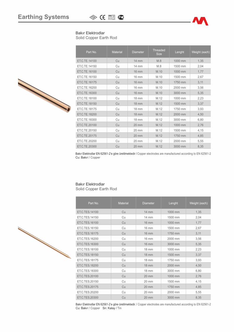
Part No. Mater�al D�ameterThreaded
S�zeLenght We�ght (each)
ET.C.TE.14100 Cu 14 mm M.8 1000 mm 1,35
ET.C.TE.14150 Cu 14 mm M.8 1500 mm 2,04
ET.C.TE.16100 Cu 16 mm M.10 1000 mm 1,77
ET.C.TE.16150 Cu 16 mm M.10 1500 mm 2,67
ET.C.TE.16175 Cu 16 mm M.10 1750 mm 3,11
ET.C.TE.16200 Cu 16 mm M.10 2000 mm 3,56
ET.C.TE.16300 Cu 16 mm M.10 3000 mm 5,35
ET.C.TE.18100 Cu 18 mm M.12 1000 mm 2,23
ET.C.TE.18150 Cu 18 mm M.12 1500 mm 3,37
ET.C.TE.18175 Cu 18 mm M.12 1750 mm 3,93
ET.C.TE.18200 Cu 18 mm M.12 2000 mm 4,50
ET.C.TE.18300 Cu 18 mm M.12 3000 mm 6,80
ET.C.TE.20100 Cu 20 mm M.12 1000 mm 2,76
ET.C.TE.20150 Cu 20 mm M.12 1500 mm 4,15
ET.C.TE.20175 Cu 20 mm M.12 1750 mm 4,85
ET.C.TE.20200 Cu 20 mm M.12 2000 mm 5,55
ET.C.TE.20300 Cu 20 mm M.12 3000 mm 8,35
Bakır ElektrodlarSol�d Copper Earth Rod
Bakır Elektrodlar EN 62561-2’e göre üret�lmekted�r / Copper electrodes are manufactured accord�ng to EN 62561-2Cu: Bakır / Copper
Part No. Mater�al D�ameter Lenght We�ght (each)
ET.C.TES.14100 Cu 14 mm 1000 mm 1,35
ET.C.TES.14150 Cu 14 mm 1500 mm 2,04
ET.C.TES.16100 Cu 16 mm 1000 mm 1,77
ET.C.TES.16150 Cu 16 mm 1500 mm 2,67
ET.C.TES.16175 Cu 16 mm 1750 mm 3,11
ET.C.TES.16200 Cu 16 mm 2000 mm 3,56
ET.C.TES.16300 Cu 16 mm 3000 mm 5,35
ET.C.TES.18100 Cu 18 mm 1000 mm 2,23
ET.C.TES.18150 Cu 18 mm 1500 mm 3,37
ET.C.TES.18175 Cu 18 mm 1750 mm 3,93
ET.C.TES.18200 Cu 18 mm 2000 mm 4,50
ET.C.TES.18300 Cu 18 mm 3000 mm 6,80
ET.C.TES.20100 Cu 20 mm 1000 mm 2,76
ET.C.TES.20150 Cu 20 mm 1500 mm 4,15
ET.C.TES.20175 Cu 20 mm 1750 mm 4,85
ET.C.TES.20200 Cu 20 mm 2000 mm 5,55
ET.C.TES.20300 Cu 20 mm 3000 mm 8,35
Bakır Elektrodlar EN 62561-2’e göre üret�lmekted�r. / Copper electrodes are manufactured accord�ng to EN 62561-2Cu: Bakır / Copper Sn: Kalay / T�n
Bakır ElektrodlarSol�d Copper Earth Rod
Earth�ng Systems
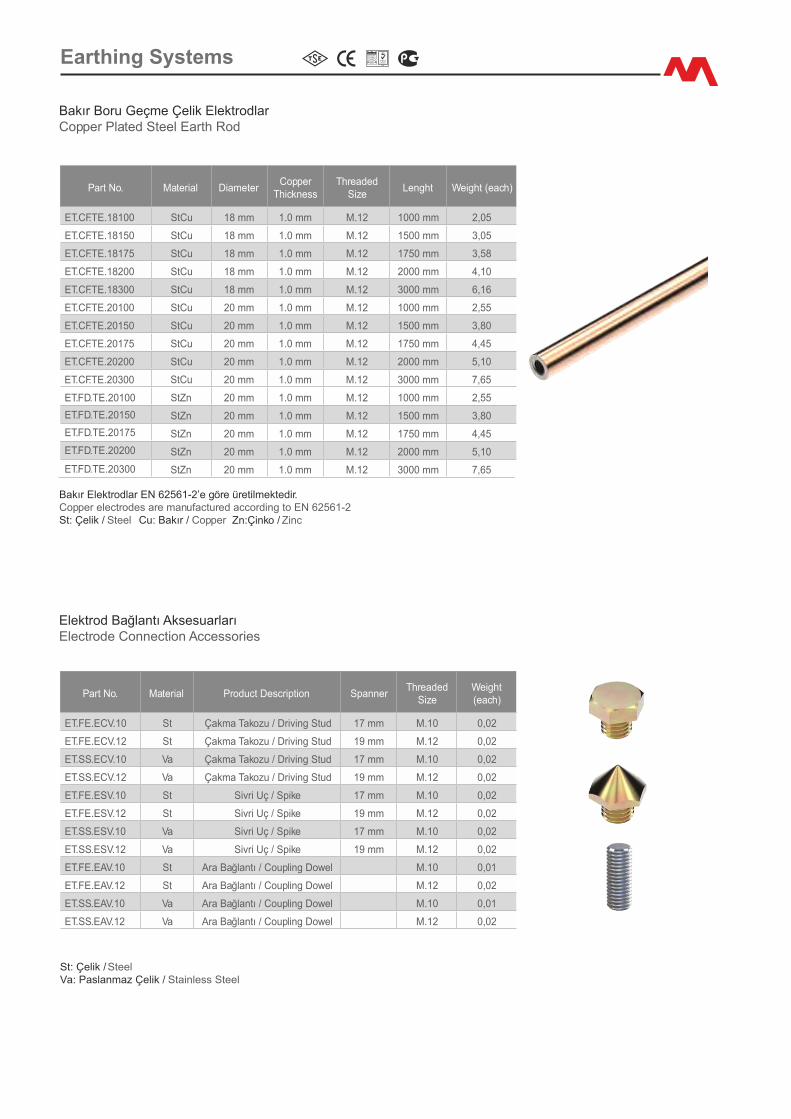
Part No. Mater�al D�ameterCopper
Th�cknessThreaded
S�zeLenght We�ght (each)
ET.CF.TE.18100 StCu 18 mm 1.0 mm M.12 1000 mm 2,05
ET.CF.TE.18150 StCu 18 mm 1.0 mm M.12 1500 mm 3,05
ET.CF.TE.18175 StCu 18 mm 1.0 mm M.12 1750 mm 3,58
ET.CF.TE.18200 StCu 18 mm 1.0 mm M.12 2000 mm 4,10
ET.CF.TE.18300 StCu 18 mm 1.0 mm M.12 3000 mm 6,16
ET.CF.TE.20100 StCu 20 mm 1.0 mm M.12 1000 mm 2,55
ET.CF.TE.20150 StCu 20 mm 1.0 mm M.12 1500 mm 3,80
ET.CF.TE.20175 StCu 20 mm 1.0 mm M.12 1750 mm 4,45
ET.CF.TE.20200 StCu 20 mm 1.0 mm M.12 2000 mm 5,10
ET.CF.TE.20300 StCu 20 mm 1.0 mm M.12 3000 mm 7,65
Bakır Boru Geçme Çel�k ElektrodlarCopper Plated Steel Earth Rod
Bakır Elektrodlar EN 62561-2’e göre üret�lmekted�r.Copper electrodes are manufactured accord�ng to EN 62561-2St: Çel�k / Steel Cu: Bakır / Copper
Part No. Mater�al Product Descr�pt�on SpannerThreaded
S�zeWe�ght (each)
ET.FE.ECV.10 St Çakma Takozu / Dr�v�ng Stud 17 mm M.10 0,02
ET.FE.ECV.12 St Çakma Takozu / Dr�v�ng Stud 19 mm M.12 0,02
ET.SS.ECV.10 Va Çakma Takozu / Dr�v�ng Stud 17 mm M.10 0,02
ET.SS.ECV.12 Va Çakma Takozu / Dr�v�ng Stud 19 mm M.12 0,02
ET.FE.ESV.10 St S�vr� Uç / Sp�ke 17 mm M.10 0,02
ET.FE.ESV.12 St S�vr� Uç / Sp�ke 19 mm M.12 0,02
ET.SS.ESV.10 Va S�vr� Uç / Sp�ke 17 mm M.10 0,02
ET.SS.ESV.12 Va S�vr� Uç / Sp�ke 19 mm M.12 0,02
ET.FE.EAV.10 St Ara Bağlantı / Coupl�ng Dowel M.10 0,01
ET.FE.EAV.12 St Ara Bağlantı / Coupl�ng Dowel M.12 0,02
ET.SS.EAV.10 Va Ara Bağlantı / Coupl�ng Dowel M.10 0,01
ET.SS.EAV.12 Va Ara Bağlantı / Coupl�ng Dowel M.12 0,02
Elektrod Bağlantı AksesuarlarıElectrode Connect�on Accessor�es
St: Çel�k / SteelVa: Paslanmaz Çel�k / Sta�nless Steel
ET.FD.TE.20100 StZn 20 mm 1.0 mm M.12 1000 mm 2,55
StZn 20 mm 1.0 mm M.12 1500 mm 3,80
StZn 20 mm 1.0 mm M.12 1750 mm 4,45
StZn 20 mm 1.0 mm M.12 2000 mm 5,10
StZn 20 mm 1.0 mm M.12 3000 mm 7,65
ET.FD.TE.20150
ET.FD.TE.20175
ET.FD.TE.20200
ET.FD.TE.20300
Earth�ng Systems
Zn:�nko / Z�nc

Galvan�z ElektrodlarHot D�p Galvan�zed Earth Rod
Galvan�z Elektrodlar EN 62561-2’e göre üret�lmekted�r.Galvan�zed electrodes are manufactured accord�ng to EN 62561-2St: Çel�k / Steel Zn:Ç�nko / Z�nc
Part No. Mater�al D�mens�ons Lenght We�ght (each)
ET.FD.TKK.404100 StZn 40x40x4 mm 1000 mm 2,40
ET.FD.TKK.404150 StZn 40x40x4 mm 1500 mm 3,60
ET.FD.TKK.505100 StZn 50x50x5 mm 1000 mm 3,90
ET.FD.TKK.505150 StZn 50x50x5 mm 1500 mm 5,80
ET.FD.TKK.505200 StZn 50x50x5 mm 2000 mm 7,80
ET.FD.TKK.604100 StZn 60x60x4 mm 1000 mm 3,70
ET.FD.TKK.604150 StZn 60x60x4 mm 1500 mm 5,60
ET.FD.TKK.604200 StZn 60x60x4 mm 2000 mm 7,40
ET.FD.TKK.605100 StZn 60x60x5 mm 1000 mm 4,60
ET.FD.TKK.605150 StZn 60x60x5 mm 1500 mm 6,90
ET.FD.TKK.605200 StZn 60x60x5 mm 2000 mm 9,10
ET.FD.TKK.606100 StZn 60x60x6 mm 1000 mm 5,40
ET.FD.TKK.606150 StZn 60x60x6 mm 1500 mm 8,10
ET.FD.TKK.606200 StZn 60x60x6 mm 2000 mm 11,00
ET.FD.TKK.655100 StZn 65x65x5 mm 1000 mm 4,90
ET.FD.TKK.655150 StZn 65x65x5 mm 1500 mm 7,50
ET.FD.TKK.655200 StZn 65x65x5 mm 2000 mm 10,00
ET.FD.TKK.656100 StZn 65x65x6 mm 1000 mm 6,20
ET.FD.TKK.656150 StZn 65x65x6 mm 1500 mm 9,00
ET.FD.TKK.656200 StZn 65x65x6 mm 2000 mm 12,00
ET.FD.TKK.657100 StZn 65x65x7 mm 1000 mm 7,00
ET.FD.TKK.657150 StZn 65x65x7 mm 1500 mm 10,50
ET.FD.TKK.657200 StZn 65x65x7 mm 2000 mm 14,00
Part No. Mater�al D�ameterD
Lenght We�ght (each)
ET.FD.TES.16100 StZn 16 mm 1000 mm 1,60
ET.FD.TES.16150 StZn 16 mm 1500 mm 2,40
ET.FD.TES.16200 StZn 16 mm 2000 mm 3,20
ET.FD.TES.18100 StZn 18 mm 1000 mm 2,00
ET.FD.TES.18150 StZn 18 mm 1500 mm 3,00
ET.FD.TES.18200 StZn 18 mm 2000 mm 4,00
ET.FD.TES.20100 StZn 20 mm 1000 mm 2,50
ET.FD.TES.20150 StZn 20 mm 1500 mm 3,75
ET.FD.TES.20200 StZn 20 mm 2000 mm 5,00
Galvan�z Elektrodlar EN 62561-2’e göre üret�lmekted�r.Galvan�zed electrodes are manufactured accord�ng to EN 62561-2St: Çel�k / Steel Zn:Ç�nko / Z�nc
Galvan�z ElektrodlarHot D�p Galvan�zed Earth Rod
Earth�ng Systems
(A*B*T)
D�ameterD
T
B
A
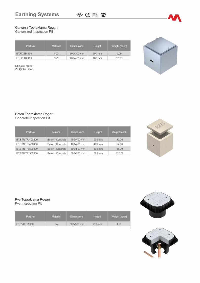
Part No. Mater�al D�mens�ons He�ght We�ght (each)
ET.PVC.TR.000 Pvc 300x300 mm 210 mm 1,80
Pvc Topraklama RogarıPvc Inspect�on P�t
Part No. Mater�al D�mens�ons He�ght We�ght (each)
ET.BTN.TR.400200 Beton / Concrete 400x400 mm 200 mm 39,00
ET.BTN.TR.400400 Beton / Concrete 400x400 mm 400 mm 57,00
ET.BTN.TR.500300 Beton / Concrete 500x500 mm 300 mm 85,00
ET.BTN.TR.500500 Beton / Concrete 500x500 mm 500 mm 120,00
Beton Topraklama RogarıConcrete Inspect�on P�t
Earth�ng Systems
Galvan�z Topraklama RogarıGalvan�zed Inspect�on P�t
Part No. Mater�al D�mens�ons He�ght We�ght (each)
ET.FD.TR.300 StZn 300x300 mm 300 mm 9,00
ET.FD.TR.400 StZn 400x400 mm 400 mm 12,90
St: Çel�k / SteelZn:Ç�nko / Z�nc
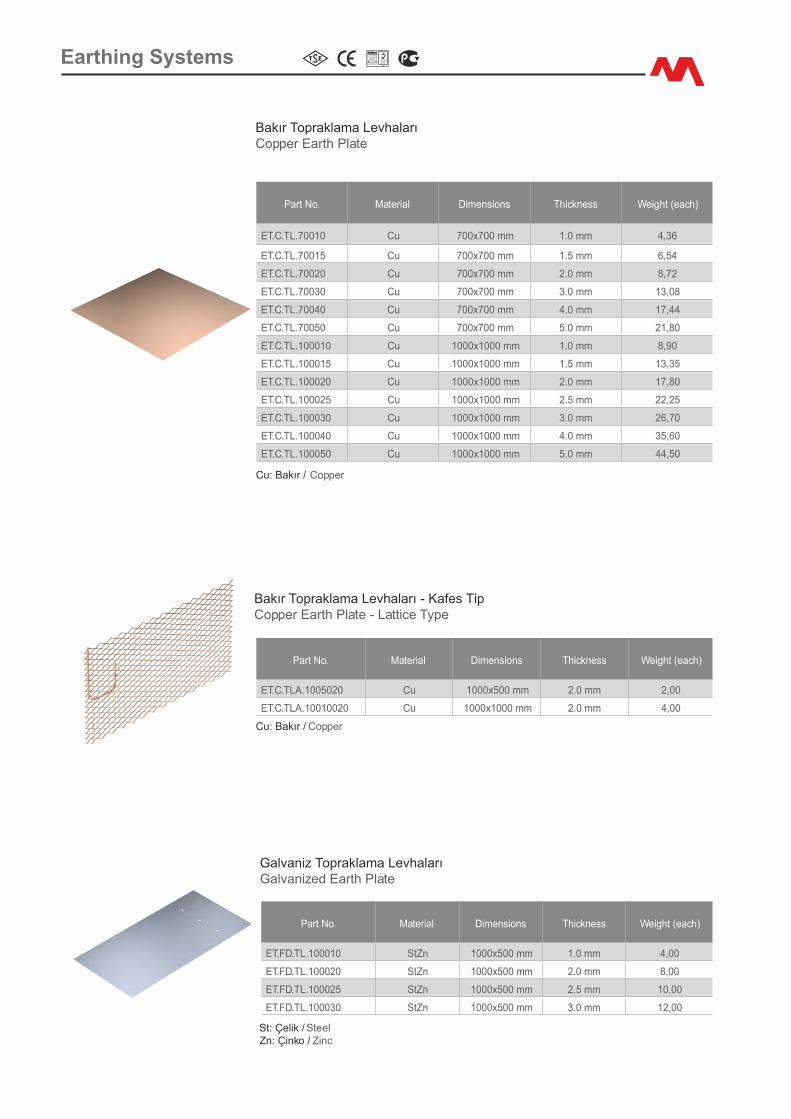
Bakır Topraklama LevhalarıCopper Earth Plate
Part No. Mater�al D�mens�ons Th�ckness We�ght (each)
ET.C.TL.70010 Cu 700x700 mm 1.0 mm 4,36
ET.C.TL.70015 Cu 700x700 mm 1.5 mm 6,54
ET.C.TL.70020 Cu 700x700 mm 2.0 mm 8,72
ET.C.TL.70030 Cu 700x700 mm 3.0 mm 13,08
ET.C.TL.70040 Cu 700x700 mm 4.0 mm 17,44
ET.C.TL.70050 Cu 700x700 mm 5.0 mm 21,80
ET.C.TL.100010 Cu 1000x1000 mm 1.0 mm 8,90
ET.C.TL.100015 Cu 1000x1000 mm 1.5 mm 13,35
ET.C.TL.100020 Cu 1000x1000 mm 2.0 mm 17,80
ET.C.TL.100025 Cu 1000x1000 mm 2.5 mm 22,25
ET.C.TL.100030 Cu 1000x1000 mm 3.0 mm 26,70
ET.C.TL.100040 Cu 1000x1000 mm 4.0 mm 35,60
ET.C.TL.100050 Cu 1000x1000 mm 5.0 mm 44,50
Part No. Mater�al D�mens�ons Th�ckness We�ght (each)
ET.C.TLA.1005020 Cu 1000x500 mm 2.0 mm 2,00
ET.C.TLA.10010020 Cu 1000x1000 mm 2.0 mm 4,00
Part No. Mater�al D�mens�ons Th�ckness We�ght (each)
ET.FD.TL.100010 StZn 1000x500 mm 1.0 mm 4,00
ET.FD.TL.100020 StZn 1000x500 mm 2.0 mm 8,00
ET.FD.TL.100025 StZn 1000x500 mm 2.5 mm 10,00
ET.FD.TL.100030 StZn 1000x500 mm 3.0 mm 12,00
Galvan�z Topraklama LevhalarıGalvan�zed Earth Plate
Bakır Topraklama Levhaları - Kafes T�pCopper Earth Plate - Latt�ce Type
Cu: Bakır / Copper
Cu: Bakır / Copper
St: Çel�k / SteelZn: Ç�nko / Z�nc
Earth�ng Systems
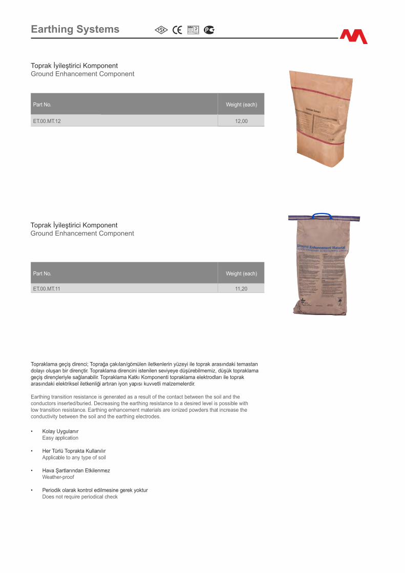
Toprak İy�leşt�r�c� KomponentGround Enhancement Component
Part No. We�ght (each)
ET.00.MT.12 12,00
Toprak İy�leşt�r�c� KomponentGround Enhancement Component
Part No. We�ght (each)
ET.00.MT.11 11,20
Topraklama geç�ş d�renc�; Toprağa çakılan/gömülen �letkenler�n yüzey� �le toprak arasındak� temastan dolayı oluşan b�r d�rençt�r. Topraklama d�renc�n� �sten�len sev�yeye düşüreb�lmem�z, düşük topraklama geç�ş d�rençler�yle sağlanab�l�r. Topraklama Katkı Komponent� topraklama elektrodları �le toprak arasındak� elektr�ksel �letkenl�ğ� artıran �yon yapısı kuvvetl� malzemelerd�r.
Earth�ng trans�t�on res�stance �s generated as a result of the contact between the so�l and the conductors �nserted/bur�ed. Decreas�ng the earth�ng res�stance to a des�red level �s poss�ble w�th low trans�t�on res�stance. Earth�ng enhancement mater�als are �on�zed powders that �ncrease the conduct�v�ty between the so�l and the earth�ng electrodes.
• Kolay UygulanırEasy appl�cat�on
• Her Türlü Toprakta Kullanılır Appl�cable to any type of so�l
• Hava Şartlarından Etk�lenmez Weather-proof
• Per�od�k olarak kontrol ed�lmes�ne gerek yokturDoes not requ�re per�od�cal check
Earth�ng Systems

Toprak İy�leşt�r�c� KomponentGround Enhancement Component
10 cm
75
cm
1
2,5
cm
Component
2
Component
Earth�ngConductor
3
ComponentComponent
4
10 c
m
Compressed ground
5Ground
6
Ro
ck,
san
d,
etc
Component
Earth Rod
Yatay (Şer�t ve Yuvarlak Kes�t) İletkenler �ç�n uygulama detayıAppl�cat�on deta�ls for str�p and round sect�on conductors
D�key Elektrodlar �ç�n uygulama detayıAppl�cat�on deta�ls for vert�cal electrodes
Earth�ng Systems

Part No. Mater�alScrew
D�ameterConductor
D�ameter (a)Conductor
D�ameter (b)We�ght (each)
ET.C.TKE.203.620E Cu M.6x20 20x3 mm 20x3 mm 0,19
ET.C.TKE.253.620E Cu M.6x20 25x3 mm 25x3 mm 0,19
ET.C.TKE.303.620E Cu M.6x20 30x3 mm 30x3 mm 0,19
ET.C.TKE.305.620E Cu M.6x20 30x5 mm 30x5 mm 0,19
ET.C.TKE.403.620E Cu M.6x20 40x3 mm 40x3 mm 0,24
ET.C.TKE.203.620SS Cu M.6x20 20x3 mm 20x3 mm 0,19
ET.C.TKE.253.620SS Cu M.6x20 25x3 mm 25x3 mm 0,19
ET.C.TKE.303.620SS Cu M.6x20 30x3 mm 30x3 mm 0,19
ET.C.TKE.305.620SS Cu M.6x20 30x5 mm 30x5 mm 0,19
ET.C.TKE.403.620SS Cu M.6x20 40x3 mm 40x3 mm 0,24
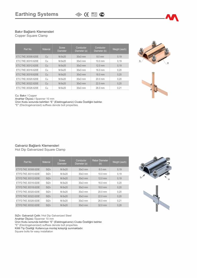
Bakır Bağlantı Klemensler�Copper Square Clamp
Cu: Bakır / CopperAnahtar Ölçüsü / Spanner 10 mmÜrün Kodu sonunda bel�rt�len “E” (Elektrogalvan�z) ve “SS” (Paslanmaz) C�vata Özell�ğ�n� bel�rler."E" (Electrogalvan�zed) and "SS" (Sta�nless) suffixes denote bolt propert�es.
ab
Part No. Mater�alScrew
D�ameterConductor
D�ameter (a)Conductor
D�ameter (b)We�ght (each)
ET.FD.TKE.203.620E StZn M.6x20 20x3 mm 20x3 mm 0,19
ET.FD.TKE.253.620E StZn M.6x20 25x3 mm 25x3 mm 0,19
ET.FD.TKE.303.620E StZn M.6x20 30x3 mm 30x3 mm 0,19
ET.FD.TKE.305.620E StZn M.6x20 30x5 mm 30x5 mm 0,19
ET.FD.TKE.404.620E StZn M.6x20 40x4 mm 40x4 mm 0,24
Galvan�z Bağlantı Klemensler�Hot D�p Galvan�zed Square Clamp
StZn: Galvan�zl� Çel�k / Hot D�p Galvan�zed SteelAnahtar Ölçüsü / Spanner 10 mmÜrün Kodu sonunda bel�rt�len “E” (Elektrogalvan�z) C�vata Özell�ğ�n� bel�rler."E" (Electrogalvan�zed) suffixes denote bolt propert�es.K�l�tl� T�p Özell�ğ�: Kullanıcıya montaj kolaylığı sunmaktadır. Square bolts for easy �nstallat�on
ba
ET.FD.TKE.505.825E StZn M.8x25 50x5 mm 50x5 mm 0,40
ET.FD.TKE.605.825E StZn M.8x25 60x5 mm 60x5 mm 0,55
Earth�ng Systems

Part No. Mater�alScrew
D�ameterConductor
D�ameter (a)Conductor
D�ameter (b)We�ght (each)
ET.C.TKE.30325.620E Cu M.6x20 30x3 mm 25 mm² 0,19
ET.C.TKE.30335.620E Cu M.6x20 30x3 mm 35 mm² 0,19
ET.C.TKE.30350.620E Cu M.6x20 30x3 mm 50 mm² 0,20
ET.C.TKE.30370.620E Cu M.6x20 30x3 mm 70 mm² 0,20
ET.C.TKE.30395.620E Cu M.6x20 30x3 mm 95 mm² 0,20
ET.C.TKE.40325.620E Cu M.6x20 40x3 mm 25 mm² 0,24
ET.C.TKE.40335.620E Cu M.6x20 40x3 mm 35 mm² 0,24
ET.C.TKE.40350.620E Cu M.6x20 40x3 mm 50 mm² 0,25
ET.C.TKE.40370.620E Cu M.6x20 40x3 mm 70 mm² 0,25
ET.C.TKE.40395.620E Cu M.6x20 40x3 mm 95 mm² 0,26
ET.C.TKE.403120.620E Cu M.6x20 40x3 mm 120 mm² 0,26
Bakır Bağlantı Klemensler�Copper Square Clamp
Cu: Bakır / CopperAnahtar Ölçüsü / Spanner 10 mmÜrün Kodu sonunda bel�rt�len “E” (Elektrogalvan�z) C�vata Özell�ğ�n� bel�rler."E" (Electrogalvan�zed) suffixes denote bolt propert�es.
ab
Part No. Mater�alScrew
D�ameterConductor
D�ameter (a)Conductor
D�ameter (b)We�ght (each)
ET.FD.TKE.30325.620E StZn M.6x20 30x3 mm 25 mm² 0,19
ET.FD.TKE.30335.620E StZn M.6x20 30x3 mm 35 mm² 0,19
ET.FD.TKE.30350.620E StZn M.6x20 30x3 mm 50 mm² 0,19
ET.FD.TKE.30370.620E StZn M.6x20 30x3 mm 70 mm² 0,20
ET.FD.TKE.30395.620E StZn M.6x20 30x3 mm 95 mm² 0,20
ET.FD.TKE.40425.620E StZn M.6x20 40x4 mm 25 mm² 0,24
ET.FD.TKE.40435.620E StZn M.6x20 40x4 mm 35 mm² 0,24
ET.FD.TKE.40450.620E StZn M.6x20 40x4 mm 50 mm² 0,24
ET.FD.TKE.40470.620E StZn M.6x20 40x4 mm 70 mm² 0,24
ET.FD.TKE.40495.620E StZn M.6x20 40x4 mm 95 mm² 0,24
ET.FD.TKE.404120.620E StZn M.6x20 40x4 mm 120 mm² 0,25
Galvan�z Bağlantı Klemensler�Hot D�p Galvan�zed Square Clamp
StZn: Galvan�zl� Çel�k / Hot D�p Galvan�zed SteelAnahtar Ölçüsü / Spanner 10 mmÜrün Kodu sonunda bel�rt�len “E” (Elektrogalvan�z) C�vata Özell�ğ�n� bel�rler."E" (Electrogalvan�zed) suffixes denote bolt propert�es.K�l�tl� T�p Özell�ğ�: Kullanıcıya montaj kolaylığı sunmaktadır. Square bolts for easy �nstallat�on
ba
Earth�ng Systems
Part No. Mater�alScrew
D�ameterConductor
D�ameter (a)Conductor
D�ameter (b)We�ght (each)
ET.C.TKE.30308.620E Cu M.6x20 30x3 mm 8.0 mm 0,19
ET.C.TKE.30310.620E Cu M.6x20 30x3 mm 10.0 mm 0,19
ET.C.TKE.30312.620E Cu M.6x20 30x3 mm 12.0 mm 0,19
ET.C.TKE.30316.620E Cu M.6x20 30x3 mm 16.0 mm 0,20
ET.C.TKE.30318.620E Cu M.6x20 30x3 mm 18.0 mm 0,20
ET.C.TKE.30320.620E Cu M.6x20 30x3 mm 20.0 mm 0,20
ET.C.TKE.30322.620E Cu M.6x20 30x3 mm 22.0 mm 0,20
ET.C.TKE.30326.620E Cu M.6x20 30x3 mm 26.0 mm 0,21
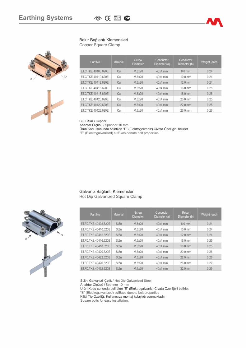
Bakır Bağlantı Klemensler�Copper Square Clamp
Cu: Bakır / CopperAnahtar Ölçüsü / Spanner 10 mmÜrün Kodu sonunda bel�rt�len “E” (Elektrogalvan�z) C�vata Özell�ğ�n� bel�rler."E" (Electrogalvan�zed) suffixes denote bolt propert�es.
ab
Part No. Mater�alScrew
D�ameterConductor
D�ameter (a)Rebar D�ameter
(b)We�ght (each)
ET.FD.TKE.30308.620E StZn M.6x20 30x3 mm 8.0 mm 0,19
ET.FD.TKE.30310.620E StZn M.6x20 30x3 mm 10.0 mm 0,19
ET.FD.TKE.30312.620E StZn M.6x20 30x3 mm 12.0 mm 0,19
ET.FD.TKE.30316.620E StZn M.6x20 30x3 mm 16.0 mm 0,20
ET.FD.TKE.30318.620E StZn M.6x20 30x3 mm 18.0 mm 0,20
ET.FD.TKE.30320.620E StZn M.6x20 30x3 mm 20.0 mm 0,20
ET.FD.TKE.30322.620E StZn M.6x20 30x3 mm 22.0 mm 0,20
ET.FD.TKE.30326.620E StZn M.6x20 30x3 mm 26.0 mm 0,21
ET.FD.TKE.30332.620E StZn M.6x20 30x3 mm 32.0 mm 0,28
Galvan�z Bağlantı Klemensler�Hot D�p Galvan�zed Square Clamp
StZn: Galvan�zl� Çel�k / Hot D�p Galvan�zed SteelAnahtar Ölçüsü / Spanner 10 mmÜrün Kodu sonunda bel�rt�len “E” (Elektrogalvan�z) C�vata Özell�ğ�n� bel�rler."E" (Electrogalvan�zed) suffixes denote bolt propert�es.K�l�tl� T�p Özell�ğ�: Kullanıcıya montaj kolaylığı sunmaktadır. Square bolts for easy �nstallat�on
ba
Earth�ng Systems
Part No. Mater�alScrew
D�ameterConductor
D�ameter (a)Conductor
D�ameter (b)We�ght (each)
ET.C.TKE.40408.620E Cu M.6x20 40x4 mm 8.0 mm 0,24
ET.C.TKE.40410.620E Cu M.6x20 40x4 mm 10.0 mm 0,24
ET.C.TKE.40412.620E Cu M.6x20 40x4 mm 12.0 mm 0,24
ET.C.TKE.40416.620E Cu M.6x20 40x4 mm 16.0 mm 0,25
ET.C.TKE.40418.620E Cu M.6x20 40x4 mm 18.0 mm 0,25
ET.C.TKE.40420.620E Cu M.6x20 40x4 mm 20.0 mm 0,25
ET.C.TKE.40422.620E Cu M.6x20 40x4 mm 22.0 mm 0,25
ET.C.TKE.40426.620E Cu M.6x20 40x4 mm 26.0 mm 0,26
Bakır Bağlantı Klemensler�Copper Square Clamp
Cu: Bakır / CopperAnahtar Ölçüsü / Spanner 10 mmÜrün Kodu sonunda bel�rt�len “E” (Elektrogalvan�z) C�vata Özell�ğ�n� bel�rler."E" (Electrogalvan�zed) sufExes denote bolt propert�es.
ab
Part No. Mater�alScrew
D�ameterConductor
D�ameter (a)Rebar
D�ameter (b)We�ght (each)
ET.FD.TKE.40408.620E StZn M.6x20 40x4 mm 8.0 mm 0,24
ET.FD.TKE.40410.620E StZn M.6x20 40x4 mm 10.0 mm 0,24
ET.FD.TKE.40412.620E StZn M.6x20 40x4 mm 12.0 mm 0,24
ET.FD.TKE.40416.620E StZn M.6x20 40x4 mm 16.0 mm 0,25
ET.FD.TKE.40418.620E StZn M.6x20 40x4 mm 18.0 mm 0,25
ET.FD.TKE.40420.620E StZn M.6x20 40x4 mm 20.0 mm 0,26
ET.FD.TKE.40422.620E StZn M.6x20 40x4 mm 22.0 mm 0,26
ET.FD.TKE.40426.620E StZn M.6x20 40x4 mm 26.0 mm 0,27
ET.FD.TKE.40432.620E StZn M.6x20 40x4 mm 32.0 mm 0,29
Galvan�z Bağlantı Klemensler�Hot D�p Galvan�zed Square Clamp
StZn: Galvan�zl� Çel�k / Hot D�p Galvan�zed Steel Anahtar Ölçüsü / Spanner 10 mmÜrün Kodu sonunda bel�rt�len “E” (Elektrogalvan�z) C�vata Özell�ğ�n� bel�rler."E" (Electrogalvan�zed) sufExes denote bolt propert�esK�l�tl� T�p Özell�ğ�: Kullanıcıya montaj kolaylığı sunmaktadır. Square bolts for easy �nstallat�on.
ba
Earth�ng Systems
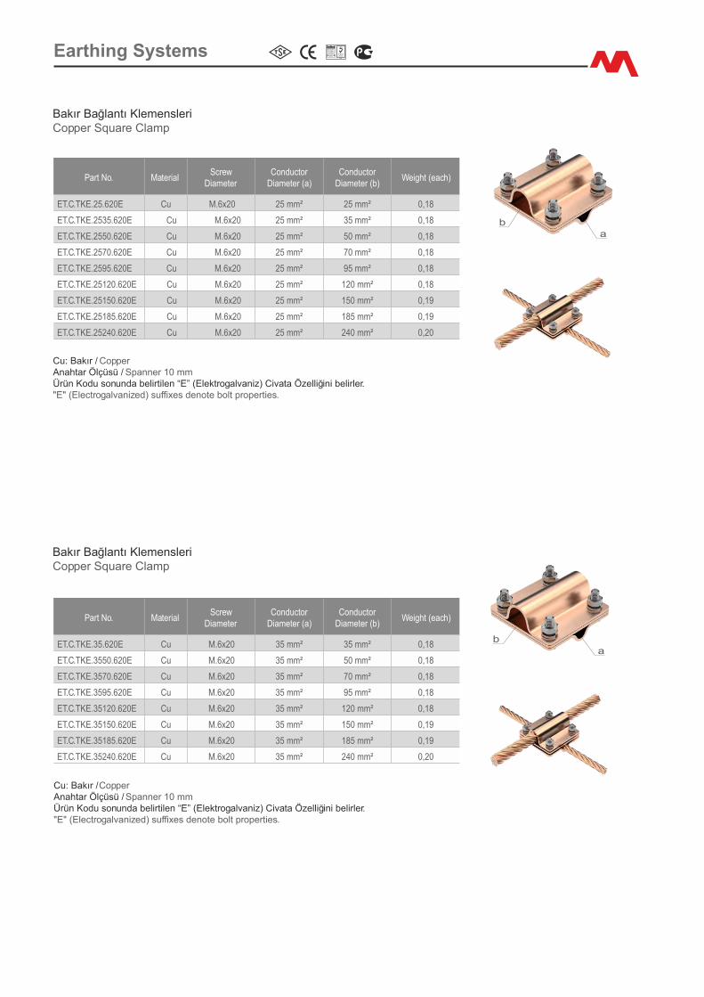
Part No. Mater�alScrew
D�ameterConductor
D�ameter (a)Conductor
D�ameter (b)We�ght (each)
ET.C.TKE.25.620E Cu M.6x20 25 mm² 25 mm² 0,18
ET.C.TKE.2535.620E Cu M.6x20 25 mm² 35 mm² 0,18
ET.C.TKE.2550.620E Cu M.6x20 25 mm² 50 mm² 0,18
ET.C.TKE.2570.620E Cu M.6x20 25 mm² 70 mm² 0,18
ET.C.TKE.2595.620E Cu M.6x20 25 mm² 95 mm² 0,18
ET.C.TKE.25120.620E Cu M.6x20 25 mm² 120 mm² 0,18
ET.C.TKE.25150.620E Cu M.6x20 25 mm² 150 mm² 0,19
ET.C.TKE.25185.620E Cu M.6x20 25 mm² 185 mm² 0,19
ET.C.TKE.25240.620E Cu M.6x20 25 mm² 240 mm² 0,20
Bakır Bağlantı Klemensler�Copper Square Clamp
Cu: Bakır / CopperAnahtar Ölçüsü / Spanner 10 mmÜrün Kodu sonunda bel�rt�len “E” (Elektrogalvan�z) C�vata Özell�ğ�n� bel�rler."E" (Electrogalvan�zed) suffixes denote bolt propert�es.
ab
Part No. Mater�alScrew
D�ameterConductor
D�ameter (a)Conductor
D�ameter (b)We�ght (each)
ET.C.TKE.35.620E Cu M.6x20 35 mm² 35 mm² 0,18
ET.C.TKE.3550.620E Cu M.6x20 35 mm² 50 mm² 0,18
ET.C.TKE.3570.620E Cu M.6x20 35 mm² 70 mm² 0,18
ET.C.TKE.3595.620E Cu M.6x20 35 mm² 95 mm² 0,18
ET.C.TKE.35120.620E Cu M.6x20 35 mm² 120 mm² 0,18
ET.C.TKE.35150.620E Cu M.6x20 35 mm² 150 mm² 0,19
ET.C.TKE.35185.620E Cu M.6x20 35 mm² 185 mm² 0,19
ET.C.TKE.35240.620E Cu M.6x20 35 mm² 240 mm² 0,20
Bakır Bağlantı Klemensler�Copper Square Clamp
Cu: Bakır / CopperAnahtar Ölçüsü / Spanner 10 mmÜrün Kodu sonunda bel�rt�len “E” (Elektrogalvan�z) C�vata Özell�ğ�n� bel�rler."E" (Electrogalvan�zed) suffixes denote bolt propert�es.
ab
Earth�ng Systems
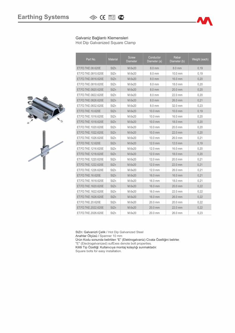
Earth�ng Systems
Part No. Mater�alScrew
D�ameterConductor
D�ameter (a)Rebar
D�ameter (b)We�ght (each)
ET.FD.TKE.08.620E StZn M.6x20 8.0 mm 8.0 mm 0,19
ET.FD.TKE.0810.620E StZn M.6x20 8.0 mm 10.0 mm 0,19
ET.FD.TKE.0816.620E StZn M.6x20 8.0 mm 16.0 mm 0,20
ET.FD.TKE.0818.620E StZn M.6x20 8.0 mm 18.0 mm 0,20
ET.FD.TKE.0820.620E StZn M.6x20 8.0 mm 20.0 mm 0,20
ET.FD.TKE.0822.620E StZn M.6x20 8.0 mm 22.0 mm 0,20
ET.FD.TKE.0826.620E StZn M.6x20 8.0 mm 26.0 mm 0,21
ET.FD.TKE.0832.620E StZn M.6x20 8.0 mm 32.0 mm 0,23
ET.FD.TKE.10.620E StZn M.6x20 10.0 mm 10.0 mm 0,19
ET.FD.TKE.1016.620E StZn M.6x20 10.0 mm 16.0 mm 0,20
ET.FD.TKE.1018.620E StZn M.6x20 10.0 mm 18.0 mm 0,20
ET.FD.TKE.1020.620E StZn M.6x20 10.0 mm 20.0 mm 0,20
ET.FD.TKE.1022.620E StZn M.6x20 10.0 mm 22.0 mm 0,20
ET.FD.TKE.1026.620E StZn M.6x20 10.0 mm 26.0 mm 0,21
ET.FD.TKE.12.620E StZn M.6x20 12.0 mm 12.0 mm 0,19
ET.FD.TKE.1216.620E StZn M.6x20 12.0 mm 16.0 mm 0,20
ET.FD.TKE.1218.620E StZn M.6x20 12.0 mm 18.0 mm 0,20
ET.FD.TKE.1220.620E StZn M.6x20 12.0 mm 20.0 mm 0,21
ET.FD.TKE.1222.620E StZn M.6x20 12.0 mm 22.0 mm 0,21
ET.FD.TKE.1226.620E StZn M.6x20 12.0 mm 26.0 mm 0,21
ET.FD.TKE.16.620E StZn M.6x20 16.0 mm 16.0 mm 0,21
ET.FD.TKE.1618.620E StZn M.6x20 16.0 mm 18.0 mm 0,21
ET.FD.TKE.1620.620E StZn M.6x20 16.0 mm 20.0 mm 0,22
ET.FD.TKE.1622.620E StZn M.6x20 16.0 mm 22.0 mm 0,22
ET.FD.TKE.1626.620E StZn M.6x20 16.0 mm 26.0 mm 0,22
ET.FD.TKE.20.620E StZn M.6x20 20.0 mm 20.0 mm 0,22
ET.FD.TKE.2022.620E StZn M.6x20 20.0 mm 22.0 mm 0,22
ET.FD.TKE.2026.620E StZn M.6x20 20.0 mm 26.0 mm 0,23
Galvan�z Bağlantı Klemensler�Hot D�p Galvan�zed Square Clamp
StZn: Galvan�zl� Çel�k / Hot D�p Galvan�zed Steel Anahtar Ölçüsü / Spanner 10 mmÜrün Kodu sonunda bel�rt�len “E” (Elektrogalvan�z) C�vata Özell�ğ�n� bel�rler."E" (Electrogalvan�zed) sufExes denote bolt propert�es.K�l�tl� T�p Özell�ğ�: Kullanıcıya montaj kolaylığı sunmaktadır. Square bolts for easy �nstallat�on.
ba

Earth�ng Systems
Part No. Mater�alScrew
D�ameterConductor
D�ameter (a)Rebar
D�ameter (b)We�ght (each)
ET.FD.TKD.30308.825E StZn M.8x25 30x3 mm 8.0 mm 0,22
ET.FD.TKD.30312.825E StZn M.8x25 30x3 mm 12.0 mm 0,22
ET.FD.TKD.30316.825E StZn M.8x25 30x3 mm 16.0 mm 0,22
ET.FD.TKD.30320.825E StZn M.8x25 30x3 mm 20.0 mm 0,22
ET.FD.TKD.30326.825E StZn M.8x25 30x3 mm 26.0 mm 0,23
ET.FD.TKD.40408.825E StZn M.8x25 40x4 mm 8.0 mm 0,26
ET.FD.TKD.40412.825E StZn M.8x25 40x4 mm 12.0 mm 0,26
ET.FD.TKD.40416.825E StZn M.8x25 40x4 mm 16.0 mm 0,26
ET.FD.TKD.40420.825E StZn M.8x25 40x4 mm 20.0 mm 0,26
ET.FD.TKD.40426.825E StZn M.8x25 40x4 mm 26.0 mm 0,27
Galvan�z D�key Bağlantı Klemensler�Hot D�p Galvan�zed Vert�cal Clamp
StZn: Galvan�zl� Çel�k / Hot D�p Galvan�zed Steel Anahtar Ölçüsü / Spanner 13 mmÜrün Kodu sonunda bel�rt�len “E” (Elektrogalvan�z) C�vata Özell�ğ�n� bel�rler."E" (Electrogalvan�zed) suffixes denote bolt propert�es.
Part No. Mater�alScrew
D�ameterConductor
D�ameter (a)Rebar
D�ameter (b)We�ght (each)
ET.FD.TKY.30308.825E StZn M.8x25 30x3 mm 8.0 mm 0,22
ET.FD.TKY.30312.825E StZn M.8x25 30x3 mm 12.0 mm 0,22
ET.FD.TKY.30316.825E StZn M.8x25 30x3 mm 16.0 mm 0,22
ET.FD.TKY.30320.825E StZn M.8x25 30x3 mm 20.0 mm 0,22
ET.FD.TKY.30322.825E StZn M.8x25 30x3 mm 22.0 mm 0,22
ET.FD.TKY.30326.825E StZn M.8x25 30x3 mm 26.0 mm 0,22
ET.FD.TKY.40408.825E StZn M.8x25 40x4 mm 8.0 mm 0,26
ET.FD.TKY.40412.825E StZn M.8x25 40x4 mm 12.0 mm 0,26
ET.FD.TKY.40416.825E StZn M.8x25 40x4 mm 16.0 mm 0,26
ET.FD.TKY.40420.825E StZn M.8x25 40x4 mm 20.0 mm 0,26
ET.FD.TKY.40422.825E StZn M.8x25 40x4 mm 22.0 mm 0,26
ET.FD.TKY.40426.825E StZn M.8x25 40x4 mm 26.0 mm 0,26
Galvan�z Yatay BağlantıHot D�p Galvan�zed Hor�zantal Clamp
StZn: Galvan�zl� Çel�k / Hot D�p Galvan�zed SteelAnahtar Ölçüsü / Spanner 13 mmÜrün Kodu sonunda bel�rt�len “E” (Elektrogalvan�z) C�vata Özell�ğ�n� bel�rler."E" (Electrogalvan�zed) suffixes denote bolt propert�es.
Part No. Mater�alScrew
D�ameterConductor
D�ameter (a)Conductor
D�ameter (b)We�ght (each)
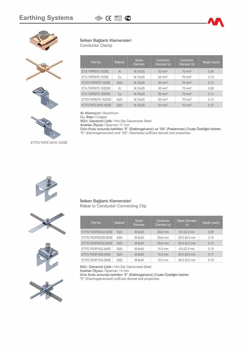
ET.A.TKP.5070.1025E Al M.10x25 50 mm² 70 mm² 0,06
ET.C.TKP.5070.1025E Cu M.10x25 50 mm² 70 mm² 0,13
ET.FD.TKP.5070.1025E StZn M.10x25 50 mm² 70 mm² 0,12
ET.A.TKP.5070.1025SS Al M.10x25 50 mm² 70 mm² 0,06
ET.C.TKP.5070.1025SS Cu M.10x25 50 mm² 70 mm² 0,13
ET.FD.TKP.5070.1025SS StZn M.10x25 50 mm² 70 mm² 0,12
ET.FD.TKPZ.5070.1025E StZn M.10x25 50 mm² 70 mm² 0,12
İletken Bağlantı Klemensler�Conductor Clamp
Al: Alümnyum / Alum�n�umCu: Bakır / CopperStZn: Galvan�zl� Çel�k / Hot D�p Galvan�zed SteelAnahtar Ölçüsü / Spanner 17 mmÜrün Kodu sonunda bel�rt�len “E” (Elektrogalvan�z) ve “SS” (Paslanmaz) C�vata Özell�ğ�n� bel�rler."E" (Electrogalvan�zed) and "SS" (Sta�nless) sufExes denote bolt propert�es.
Part No. Mater�alScrew
D�ameterConductor
D�ameter (a)Rebar D�ameter
(b)We�ght (each)
ET.FD.TKOP.30322.820E StZn M.8x20 30x3 mm 8.0-22.0 mm 0,08
ET.FD.TKOP.30326.820E StZn M.8x20 30x3 mm 20.0-26.0 mm 0,10
ET.FD.TKOP.30332.820E StZn M.8x20 30x3 mm 26.0-32.0 mm 0,12
ET.FD.TKOP.1022.840E StZn M.8x40 10.0 mm 8.0-22.0 mm 0,15
ET.FD.TKOP.1026.840E StZn M.8x40 10.0 mm 20.0-26.0 mm 0,17
ET.FD.TKOP.1032.840E StZn M.8x40 10.0 mm 26.0-32.0 mm 0,19
İletken Bağlantı Klemensler�Rebar to Conductor Connect�ng Cl�p
StZn: Galvan�zl� Çel�k / Hot D�p Galvan�zed Steel Anahtar Ölçüsü / Spanner 13 mmÜrün Kodu sonunda bel�rt�len “E” (Elektrogalvan�z) C�vata Özell�ğ�n� bel�rler."E" (Electrogalvan�zed) sufExes denote bolt propert�es.
ET.FD.TKPZ.5070.1025E
Earth�ng Systems
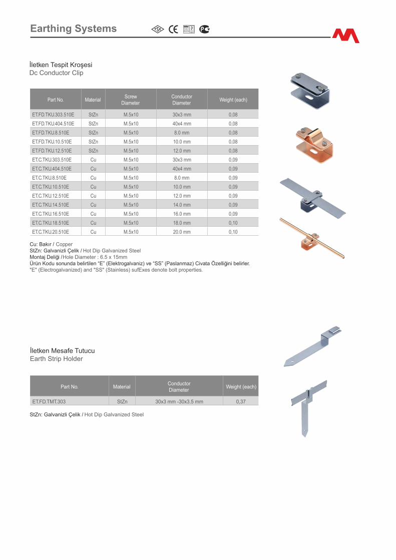
İletken Tesp�t Kroşes�Dc Conductor Cl�p
Part No. Mater�alScrew
D�ameterConductorD�ameter
We�ght (each)
ET.FD.TKU.303.510E StZn M.5x10 30x3 mm 0,08
ET.FD.TKU.404.510E StZn M.5x10 40x4 mm 0,08
ET.FD.TKU.8.510E StZn M.5x10 8.0 mm 0,08
ET.FD.TKU.10.510E StZn M.5x10 10.0 mm 0,08
ET.FD.TKU.12.510E StZn M.5x10 12.0 mm 0,08
ET.C.TKU.303.510E Cu M.5x10 30x3 mm 0,09
ET.C.TKU.404.510E Cu M.5x10 40x4 mm 0,09
ET.C.TKU.8.510E Cu M.5x10 8.0 mm 0,09
ET.C.TKU.10.510E Cu M.5x10 10.0 mm 0,09
ET.C.TKU.12.510E Cu M.5x10 12.0 mm 0,09
ET.C.TKU.14.510E Cu M.5x10 14.0 mm 0,09
ET.C.TKU.16.510E Cu M.5x10 16.0 mm 0,09
ET.C.TKU.18.510E Cu M.5x10 18.0 mm 0,10
ET.C.TKU.20.510E Cu M.5x10 20.0 mm 0,10
Cu: Bakır / CopperStZn: Galvan�zl� Çel�k / Hot D�p Galvan�zed SteelMontaj Del�ğ� / Hole D�ameter : 6.5 x 15mmÜrün Kodu sonunda bel�rt�len “E” (Elektrogalvan�z) ve “SS” (Paslanmaz) C�vata Özell�ğ�n� bel�rler."E" (Electrogalvan�zed) and "SS" (Sta�nless) sufExes denote bolt propert�es.
Part No. Mater�alConductorD�ameter
We�ght (each)
ET.FD.TMT.303 StZn 30x3 mm -30x3.5 mm 0,37
İletken Mesafe TutucuEarth Str�p Holder
StZn: Galvan�zl� Çel�k / Hot D�p Galvan�zed Steel
Earth�ng Systems

Part No. Mater�alScrew
D�ameterRod
D�ameterConductor D�ameter
We�ght (each)
ET.C.EKH.14150.620E Cu M.6x20 14.0 mm 50 mm² 0,06
ET.C.EKH.16110.620E Cu M.6x20 16.0 mm 10 mm² 0,06
ET.C.EKH.16116.620E Cu M.6x20 16.0 mm 16 mm² 0,06
ET.C.EKH.16125.620E Cu M.6x20 16.0 mm 25 mm² 0,06
ET.C.EKH.16135.620E Cu M.6x20 16.0 mm 35 mm² 0,06
ET.C.EKH.16150.620E Cu M.6x20 16.0 mm 50 mm² 0,06
ET.C.EKH.16170.620E Cu M.6x20 16.0 mm 70 mm² 0,06
ET.C.EKH.16195.620E Cu M.6x20 16.0 mm 95 mm² 0,06
ET.C.EKH.161120.620E Cu M.6x20 16.0 mm 120 mm² 0,06
ET.C.EKH.18110.620E Cu M.6x20 18.0 mm 10 mm² 0,06
ET.C.EKH.18116.620E Cu M.6x20 18.0 mm 16 mm² 0,06
ET.C.EKH.18125.620E Cu M.6x20 18.0 mm 25 mm² 0,06
ET.C.EKH.18135.620E Cu M.6x20 18.0 mm 35 mm² 0,06
ET.C.EKH.18150.620E Cu M.6x20 18.0 mm 50 mm² 0,06
ET.C.EKH.18170.620E Cu M.6x20 18.0 mm 70 mm² 0,06
ET.C.EKH.18195.620E Cu M.6x20 18.0 mm 95 mm² 0,06
ET.C.EKH.181120.620E Cu M.6x20 18.0 mm 120 mm² 0,06
ET.C.EKH.20110.620E Cu M.6x20 20.0 mm 10 mm² 0,06
ET.C.EKH.20116.620E Cu M.6x20 20.0 mm 16 mm² 0,06
ET.C.EKH.20125.620E Cu M.6x20 20.0 mm 25 mm² 0,06
ET.C.EKH.20135.620E Cu M.6x20 20.0 mm 35 mm² 0,06
ET.C.EKH.20150.620E Cu M.6x20 20.0 mm 50 mm² 0,06
ET.C.EKH.20170.620E Cu M.6x20 20.0 mm 70 mm² 0,06
ET.C.EKH.20195.620E Cu M.6x20 20.0 mm 95 mm² 0,06
ET.C.EKH.201120.620E Cu M.6x20 20.0 mm 120 mm² 0,06
Elektrod Bağlantı Klemensler� (H T�p�)Rod to Cable Clamp (Type H)
Cu:Bakır / Copper Anahtar Ölçüsü / Spanner 10 mmÜrün Kodu sonunda bel�rt�len “E”(Elektrogalvan�z) ve “SS” (Paslanmaz) C�vata Özell�ğ�n� bel�rler."E" (Electrogalvan�zed) and "SS" (Sta�nless) suffixes denote bolt propert�es.
Part No. Mater�alScrew
D�ameterRod
D�ameter Hole
D�ameterWe�ght (each)
ET.C.EKK.16M8.620E Cu M.6x20 16.0 mm 8.5 mm 0,07
ET.C.EKK.18M8.620E Cu M.6x20 18.0 mm 8.5 mm 0,07
ET.C.EKK.20M8.620E Cu M.6x20 20.0 mm 8.5 mm 0,07
ET.C.EKK.22M8.620E Cu M.6x20 22.0 mm 8.5 mm 0,07
Cu: Bakır / Copper Anahtar Ölçüsü / Spanner 10 mmÜrün Kodu sonunda bel�rt�len “E” (Elektrogalvan�z) ve “SS” (Paslanmaz) C�vata Özell�ğ�n� bel�rler."E" (Electrogalvan�zed) and "SS" (Sta�nless) suffixes denote bolt propert�es.
Elektrod Bağlantı Klemensler� (K T�p�)Rod to Cable Clamp (Type K)
Earth�ng Systems
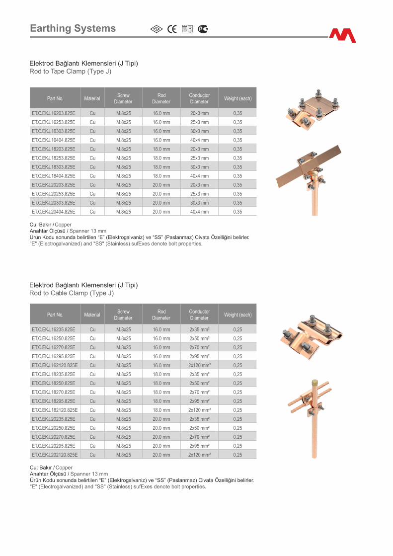
Elektrod Bağlantı Klemensler� (J T�p�)Rod to Tape Clamp (Type J)
Part No. Mater�alScrew
D�ameterRod
D�ameterConductor D�ameter
We�ght (each)
ET.C.EKJ.16203.825E Cu M.8x25 16.0 mm 20x3 mm 0,35
ET.C.EKJ.16253.825E Cu M.8x25 16.0 mm 25x3 mm 0,35
ET.C.EKJ.16303.825E Cu M.8x25 16.0 mm 30x3 mm 0,35
ET.C.EKJ.16404.825E Cu M.8x25 16.0 mm 40x4 mm 0,35
ET.C.EKJ.18203.825E Cu M.8x25 18.0 mm 20x3 mm 0,35
ET.C.EKJ.18253.825E Cu M.8x25 18.0 mm 25x3 mm 0,35
ET.C.EKJ.18303.825E Cu M.8x25 18.0 mm 30x3 mm 0,35
ET.C.EKJ.18404.825E Cu M.8x25 18.0 mm 40x4 mm 0,35
ET.C.EKJ.20203.825E Cu M.8x25 20.0 mm 20x3 mm 0,35
ET.C.EKJ.20253.825E Cu M.8x25 20.0 mm 25x3 mm 0,35
ET.C.EKJ.20303.825E Cu M.8x25 20.0 mm 30x3 mm 0,35
ET.C.EKJ.20404.825E Cu M.8x25 20.0 mm 40x4 mm 0,35
Cu: Bakır / Copper Anahtar Ölçüsü / Spanner 13 mmÜrün Kodu sonunda bel�rt�len “E” (Elektrogalvan�z) ve “SS” (Paslanmaz) C�vata Özell�ğ�n� bel�rler."E" (Electrogalvan�zed) and "SS" (Sta�nless) sufExes denote bolt propert�es.
Elektrod Bağlantı Klemensler� (J T�p�)Rod to Cable Clamp (Type J)
Part No. Mater�alScrew
D�ameterRod
D�ameterConductor D�ameter
We�ght (each)
ET.C.EKJ.16235.825E Cu M.8x25 16.0 mm 2x35 mm² 0,25
ET.C.EKJ.16250.825E Cu M.8x25 16.0 mm 2x50 mm² 0,25
ET.C.EKJ.16270.825E Cu M.8x25 16.0 mm 2x70 mm² 0,25
ET.C.EKJ.16295.825E Cu M.8x25 16.0 mm 2x95 mm² 0,25
ET.C.EKJ.162120.825E Cu M.8x25 16.0 mm 2x120 mm² 0,25
ET.C.EKJ.18235.825E Cu M.8x25 18.0 mm 2x35 mm² 0,25
ET.C.EKJ.18250.825E Cu M.8x25 18.0 mm 2x50 mm² 0,25
ET.C.EKJ.18270.825E Cu M.8x25 18.0 mm 2x70 mm² 0,25
ET.C.EKJ.18295.825E Cu M.8x25 18.0 mm 2x95 mm² 0,25
ET.C.EKJ.182120.825E Cu M.8x25 18.0 mm 2x120 mm² 0,25
ET.C.EKJ.20235.825E Cu M.8x25 20.0 mm 2x35 mm² 0,25
ET.C.EKJ.20250.825E Cu M.8x25 20.0 mm 2x50 mm² 0,25
ET.C.EKJ.20270.825E Cu M.8x25 20.0 mm 2x70 mm² 0,25
ET.C.EKJ.20295.825E Cu M.8x25 20.0 mm 2x95 mm² 0,25
ET.C.EKJ.202120.825E Cu M.8x25 20.0 mm 2x120 mm² 0,25
Cu: Bakır / Copper Anahtar Ölçüsü / Spanner 13 mmÜrün Kodu sonunda bel�rt�len “E” (Elektrogalvan�z) ve “SS” (Paslanmaz) C�vata Özell�ğ�n� bel�rler."E" (Electrogalvan�zed) and "SS" (Sta�nless) sufExes denote bolt propert�es.
Earth�ng Systems
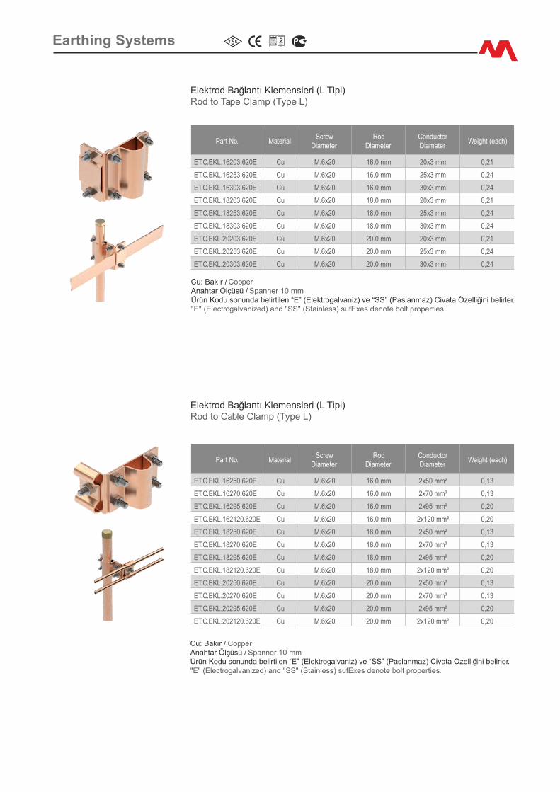
Elektrod Bağlantı Klemensler� (L T�p�)Rod to Tape Clamp (Type L)
Part No. Mater�alScrew
D�ameterRod
D�ameterConductor D�ameter
We�ght (each)
ET.C.EKL.16203.620E Cu M.6x20 16.0 mm 20x3 mm 0,21
ET.C.EKL.16253.620E Cu M.6x20 16.0 mm 25x3 mm 0,24
ET.C.EKL.16303.620E Cu M.6x20 16.0 mm 30x3 mm 0,24
ET.C.EKL.18203.620E Cu M.6x20 18.0 mm 20x3 mm 0,21
ET.C.EKL.18253.620E Cu M.6x20 18.0 mm 25x3 mm 0,24
ET.C.EKL.18303.620E Cu M.6x20 18.0 mm 30x3 mm 0,24
ET.C.EKL.20203.620E Cu M.6x20 20.0 mm 20x3 mm 0,21
ET.C.EKL.20253.620E Cu M.6x20 20.0 mm 25x3 mm 0,24
ET.C.EKL.20303.620E Cu M.6x20 20.0 mm 30x3 mm 0,24
Cu: Bakır / Copper Anahtar Ölçüsü / Spanner 10 mmÜrün Kodu sonunda bel�rt�len “E” (Elektrogalvan�z) ve “SS” (Paslanmaz) C�vata Özell�ğ�n� bel�rler."E" (Electrogalvan�zed) and "SS" (Sta�nless) sufExes denote bolt propert�es.
Elektrod Bağlantı Klemensler� (L T�p�)Rod to Cable Clamp (Type L)
Part No. Mater�alScrew
D�ameterRod
D�ameterConductor D�ameter
We�ght (each)
ET.C.EKL.16250.620E Cu M.6x20 16.0 mm 2x50 mm² 0,13
ET.C.EKL.16270.620E Cu M.6x20 16.0 mm 2x70 mm² 0,13
ET.C.EKL.16295.620E Cu M.6x20 16.0 mm 2x95 mm² 0,20
ET.C.EKL.162120.620E Cu M.6x20 16.0 mm 2x120 mm² 0,20
ET.C.EKL.18250.620E Cu M.6x20 18.0 mm 2x50 mm² 0,13
ET.C.EKL.18270.620E Cu M.6x20 18.0 mm 2x70 mm² 0,13
ET.C.EKL.18295.620E Cu M.6x20 18.0 mm 2x95 mm² 0,20
ET.C.EKL.182120.620E Cu M.6x20 18.0 mm 2x120 mm² 0,20
ET.C.EKL.20250.620E Cu M.6x20 20.0 mm 2x50 mm² 0,13
ET.C.EKL.20270.620E Cu M.6x20 20.0 mm 2x70 mm² 0,13
ET.C.EKL.20295.620E Cu M.6x20 20.0 mm 2x95 mm² 0,20
ET.C.EKL.202120.620E Cu M.6x20 20.0 mm 2x120 mm² 0,20
Cu: Bakır / Copper Anahtar Ölçüsü / Spanner 10 mmÜrün Kodu sonunda bel�rt�len “E” (Elektrogalvan�z) ve “SS” (Paslanmaz) C�vata Özell�ğ�n� bel�rler."E" (Electrogalvan�zed) and "SS" (Sta�nless) sufExes denote bolt propert�es.
Earth�ng Systems
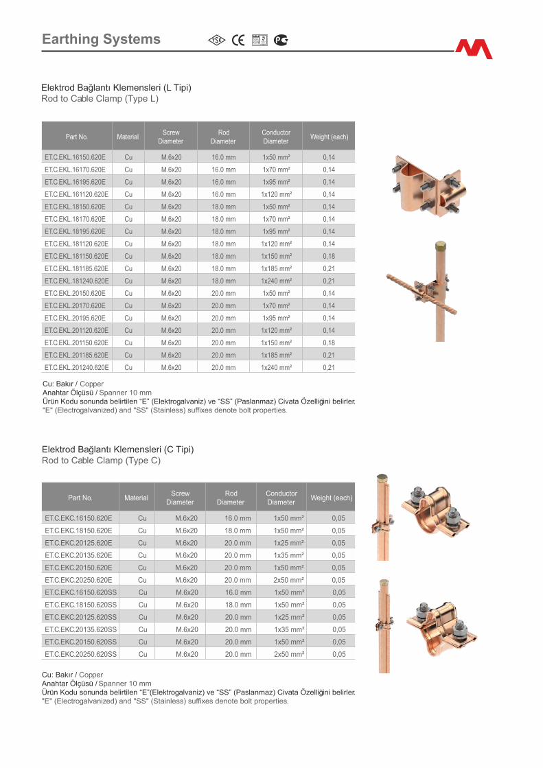
Part No. Mater�alScrew
D�ameterRod
D�ameterConductor D�ameter
We�ght (each)
ET.C.EKL.16150.620E Cu M.6x20 16.0 mm 1x50 mm² 0,14
ET.C.EKL.16170.620E Cu M.6x20 16.0 mm 1x70 mm² 0,14
ET.C.EKL.16195.620E Cu M.6x20 16.0 mm 1x95 mm² 0,14
ET.C.EKL.161120.620E Cu M.6x20 16.0 mm 1x120 mm² 0,14
ET.C.EKL.18150.620E Cu M.6x20 18.0 mm 1x50 mm² 0,14
ET.C.EKL.18170.620E Cu M.6x20 18.0 mm 1x70 mm² 0,14
ET.C.EKL.18195.620E Cu M.6x20 18.0 mm 1x95 mm² 0,14
ET.C.EKL.181120.620E Cu M.6x20 18.0 mm 1x120 mm² 0,14
ET.C.EKL.181150.620E Cu M.6x20 18.0 mm 1x150 mm² 0,18
ET.C.EKL.181185.620E Cu M.6x20 18.0 mm 1x185 mm² 0,21
ET.C.EKL.181240.620E Cu M.6x20 18.0 mm 1x240 mm² 0,21
ET.C.EKL.20150.620E Cu M.6x20 20.0 mm 1x50 mm² 0,14
ET.C.EKL.20170.620E Cu M.6x20 20.0 mm 1x70 mm² 0,14
ET.C.EKL.20195.620E Cu M.6x20 20.0 mm 1x95 mm² 0,14
ET.C.EKL.201120.620E Cu M.6x20 20.0 mm 1x120 mm² 0,14
ET.C.EKL.201150.620E Cu M.6x20 20.0 mm 1x150 mm² 0,18
ET.C.EKL.201185.620E Cu M.6x20 20.0 mm 1x185 mm² 0,21
ET.C.EKL.201240.620E Cu M.6x20 20.0 mm 1x240 mm² 0,21
Elektrod Bağlantı Klemensler� (L T�p�)Rod to Cable Clamp (Type L)
Cu: Bakır / Copper Anahtar Ölçüsü / Spanner 10 mmÜrün Kodu sonunda bel�rt�len “E” (Elektrogalvan�z) ve “SS” (Paslanmaz) C�vata Özell�ğ�n� bel�rler."E" (Electrogalvan�zed) and "SS" (Sta�nless) suffixes denote bolt propert�es.
Part No. Mater�alScrew
D�ameterRod
D�ameterConductor D�ameter
We�ght (each)
ET.C.EKC.16150.620E Cu M.6x20 16.0 mm 1x50 mm² 0,05
ET.C.EKC.18150.620E Cu M.6x20 18.0 mm 1x50 mm² 0,05
ET.C.EKC.20125.620E Cu M.6x20 20.0 mm 1x25 mm² 0,05
ET.C.EKC.20135.620E Cu M.6x20 20.0 mm 1x35 mm² 0,05
ET.C.EKC.20150.620E Cu M.6x20 20.0 mm 1x50 mm² 0,05
ET.C.EKC.20250.620E Cu M.6x20 20.0 mm 2x50 mm² 0,05
ET.C.EKC.16150.620SS Cu M.6x20 16.0 mm 1x50 mm² 0,05
ET.C.EKC.18150.620SS Cu M.6x20 18.0 mm 1x50 mm² 0,05
ET.C.EKC.20125.620SS Cu M.6x20 20.0 mm 1x25 mm² 0,05
ET.C.EKC.20135.620SS Cu M.6x20 20.0 mm 1x35 mm² 0,05
ET.C.EKC.20150.620SS Cu M.6x20 20.0 mm 1x50 mm² 0,05
ET.C.EKC.20250.620SS Cu M.6x20 20.0 mm 2x50 mm² 0,05
Elektrod Bağlantı Klemensler� (C T�p�)Rod to Cable Clamp (Type C)
Cu: Bakır / Copper Anahtar Ölçüsü / Spanner 10 mmÜrün Kodu sonunda bel�rt�len “E”(Elektrogalvan�z) ve “SS” (Paslanmaz) C�vata Özell�ğ�n� bel�rler."E" (Electrogalvan�zed) and "SS" (Sta�nless) suffixes denote bolt propert�es.
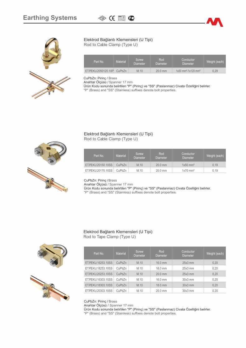
Earth�ng Systems
Part No. Mater�alScrew
D�ameterRod
D�ameterConductorD�ameter
We�ght (each)
ET.P.EKU.2050120.10P CuPbZn M.10 20.0 mm 1x50 mm²-1x120 mm² 0,29
Elektrod Bağlantı Klemensler� (U T�p�)Rod to Cable Clamp (Type U)
CuPbZn: P�r�nç / Brass Anahtar Ölçüsü / Spanner 17 mmÜrün Kodu sonunda bel�rt�len "P" (P�r�nç) ve "SS" (Paslanmaz) C�vata Özell�ğ�n� bel�rler. "P" (Brass) and "SS" (Sta�nless) suffixes denote bolt propert�es.
Elektrod Bağlantı Klemensler� (U T�p�)Rod to Cable Clamp (Type U)
Part No. Mater�alScrew
D�ameterRod
D�ameterConductorD�ameter
We�ght (each)
ET.P.EKU.20150.10SS CuPbZn M.10 20.0 mm 1x50 mm² 0,19
ET.P.EKU.20170.10SS CuPbZn M.10 20.0 mm 1x70 mm² 0,19
CuPbZn: P�r�nç / Brass Anahtar Ölçüsü / Spanner 17 mmÜrün Kodu sonunda bel�rt�len "P" (P�r�nç) ve "SS" (Paslanmaz) C�vata Özell�ğ�n� bel�rler. "P" (Brass) and "SS" (Sta�nless) suffixes denote bolt propert�es.
Elektrod Bağlantı Klemensler� (U T�p�)Rod to Tape Clamp (Type U)
Part No. Mater�alScrew
D�ameterRod
D�ameterConductorD�ameter
We�ght (each)
ET.P.EKU.16253.10SS CuPbZn M.10 16.0 mm 25x3 mm 0,20
ET.P.EKU.18253.10SS CuPbZn M.10 18.0 mm 25x3 mm 0,20
ET.P.EKU.20253.10SS CuPbZn M.10 20.0 mm 25x3 mm 0,20
ET.P.EKU.16303.10SS CuPbZn M.10 16.0 mm 30x3 mm 0,20
ET.P.EKU.18303.10SS CuPbZn M.10 18.0 mm 30x3 mm 0,20
ET.P.EKU.20303.10SS CuPbZn M.10 20.0 mm 30x3 mm 0,20
CuPbZn: P�r�nç / Brass Anahtar Ölçüsü / Spanner 17 mmÜrün Kodu sonunda bel�rt�len "P" (P�r�nç) ve "SS" (Paslanmaz) C�vata Özell�ğ�n� bel�rler. "P" (Brass) and "SS" (Sta�nless) suffixes denote bolt propert�es.
Earth�ng Systems
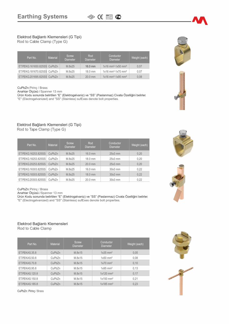
Elektrod Bağlantı Klemensler� (G T�p�)Rod to Cable Clamp (Type G)
CuPbZn: P�r�nç / Brass Anahtar Ölçüsü / Spanner 13 mmÜrün Kodu sonunda bel�rt�len “E” (Elektrogalvan�z) ve “SS” (Paslanmaz) C�vata Özell�ğ�n� bel�rler."E" (Electrogalvan�zed) and "SS" (Sta�nless) sufExes denote bolt propert�es.
Elektrod Bağlantı Klemensler� (G T�p�)Rod to Tape Clamp (Type G)
Part No. Mater�alScrew
D�ameterRod
D�ameterConductorD�ameter
We�ght (each)
ET.P.EKG.161650.825SS CuPbZn M.8x25 16.0 mm 1x16 mm²-1x50 mm² 0,07
ET.P.EKG.181670.825SS CuPbZn M.8x25 18.0 mm 1x16 mm²-1x70 mm² 0,07
ET.P.EKG.201695.825SS CuPbZn M.8x25 20.0 mm 1x16 mm²-1x95 mm² 0,08
Part No. Mater�alScrew
D�ameterRod
D�ameterConductorD�ameter
We�ght (each)
ET.P.EKG.16253.825SS CuPbZn M.8x25 16.0 mm 25x3 mm 0,20
ET.P.EKG.18253.825SS CuPbZn M.8x25 18.0 mm 25x3 mm 0,20
ET.P.EKG.20253.825SS CuPbZn M.8x25 20.0 mm 25x3 mm 0,20
ET.P.EKG.16303.825SS CuPbZn M.8x25 16.0 mm 30x3 mm 0,22
ET.P.EKG.18303.825SS CuPbZn M.8x25 18.0 mm 30x3 mm 0,22
ET.P.EKG.20303.825SS CuPbZn M.8x25 20.0 mm 30x3 mm 0,22
CuPbZn: P�r�nç / Brass Anahtar Ölçüsü / Spanner 13 mmÜrün Kodu sonunda bel�rt�len “E” (Elektrogalvan�z) ve “SS” (Paslanmaz) C�vata Özell�ğ�n� bel�rler."E" (Electrogalvan�zed) and "SS" (Sta�nless) sufExes denote bolt propert�es.
Earth�ng Systems
Part No. Mater�alScrew
D�ameterConductorD�ameter
We�ght (each)
ET.P.EKAS.35.8 CuPbZn M.8x15 1x35 mm² 0,05
ET.P.EKAS.50.8 CuPbZn M.8x15 1x50 mm² 0,08
ET.P.EKAS.70.8 CuPbZn M.8x15 1x70 mm² 0,10
ET.P.EKAS.95.8 CuPbZn M.8x15 1x95 mm² 0,13
ET.P.EKAS.120.8 CuPbZn M.8x15 1x120 mm² 0,17
ET.P.EKAS.150.8 CuPbZn M.8x15 1x150 mm² 0,21
ET.P.EKAS.185.8 CuPbZn M.8x15 1x185 mm² 0,23
Elektrod Bağlantı Klemensler� Rod to Cable Clamp
CuPbZn: P�r�nç / Brass
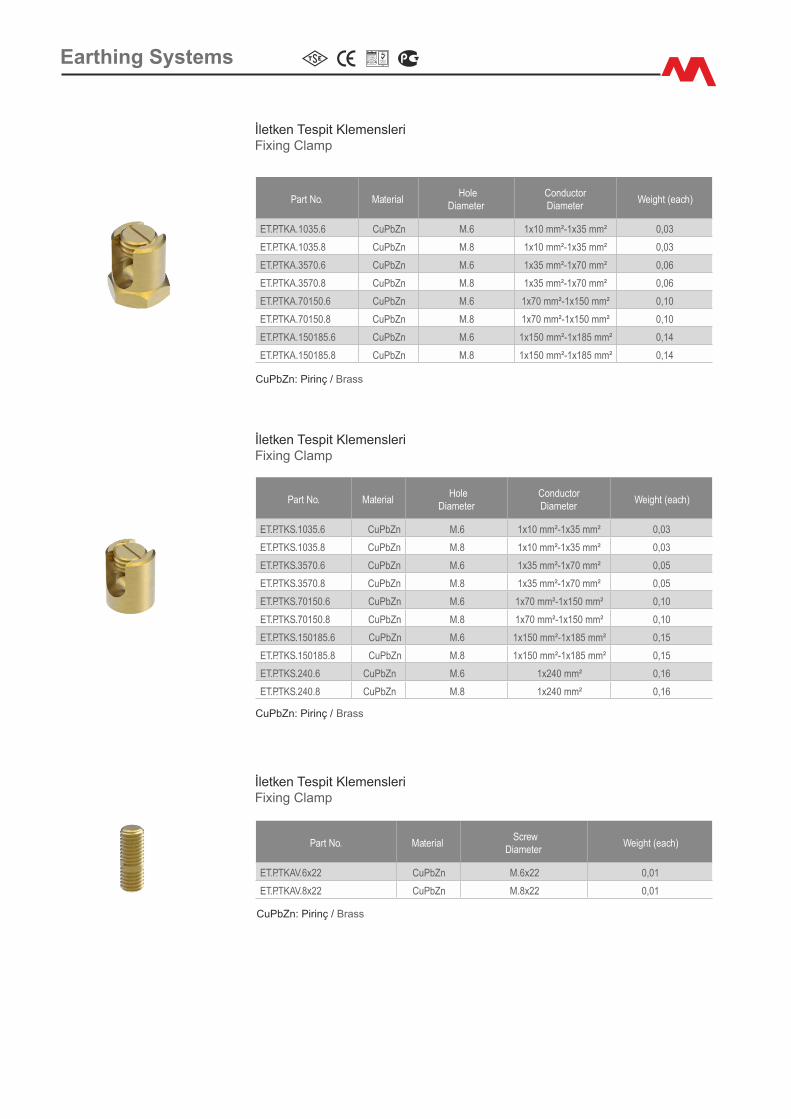
İletken Tesp�t Klemensler�F�x�ng Clamp
Part No. Mater�al Hole
D�ameterConductorD�ameter
We�ght (each)
ET.P.TKA.1035.6 CuPbZn M.6 1x10 mm²-1x35 mm² 0,03
ET.P.TKA.1035.8 CuPbZn M.8 1x10 mm²-1x35 mm² 0,03
ET.P.TKA.3570.6 CuPbZn M.6 1x35 mm²-1x70 mm² 0,06
ET.P.TKA.3570.8 CuPbZn M.8 1x35 mm²-1x70 mm² 0,06
ET.P.TKA.70150.6 CuPbZn M.6 1x70 mm²-1x150 mm² 0,10
ET.P.TKA.70150.8 CuPbZn M.8 1x70 mm²-1x150 mm² 0,10
ET.P.TKA.150185.6 CuPbZn M.6 1x150 mm²-1x185 mm² 0,14
ET.P.TKA.150185.8 CuPbZn M.8 1x150 mm²-1x185 mm² 0,14
CuPbZn: P�r�nç / Brass
Part No. Mater�al Hole
D�ameterConductorD�ameter
We�ght (each)
ET.P.TKS.1035.6 CuPbZn M.6 1x10 mm²-1x35 mm² 0,03
ET.P.TKS.1035.8 CuPbZn M.8 1x10 mm²-1x35 mm² 0,03
ET.P.TKS.3570.6 CuPbZn M.6 1x35 mm²-1x70 mm² 0,05
ET.P.TKS.3570.8 CuPbZn M.8 1x35 mm²-1x70 mm² 0,05
ET.P.TKS.70150.6 CuPbZn M.6 1x70 mm²-1x150 mm² 0,10
ET.P.TKS.70150.8 CuPbZn M.8 1x70 mm²-1x150 mm² 0,10
ET.P.TKS.150185.6 CuPbZn M.6 1x150 mm²-1x185 mm² 0,15
ET.P.TKS.150185.8 CuPbZn M.8 1x150 mm²-1x185 mm² 0,15
ET.P.TKS.240.6 CuPbZn M.6 1x240 mm² 0,16
ET.P.TKS.240.8 CuPbZn M.8 1x240 mm² 0,16
İletken Tesp�t Klemensler�F�x�ng Clamp
CuPbZn: P�r�nç / Brass
İletken Tesp�t Klemensler�F�x�ng Clamp
Part No. Mater�al Screw
D�ameterWe�ght (each)
ET.P.TKAV.6x22 CuPbZn M.6x22 0,01
ET.P.TKAV.8x22 CuPbZn M.8x22 0,01
CuPbZn: P�r�nç / Brass
Earth�ng Systems

Part No. Mater�al Hole
D�ameterConductorD�ameter
We�ght (each)
ET.P.TKS.21035.6 CuPbZn M.6 2x10 mm²-2x35 mm² 0,04
ET.P.TKS.21035.8 CuPbZn M.8 2x10 mm²-2x35 mm² 0,04
ET.P.TKS.23570.6 CuPbZn M.6 2x35 mm²-2x70 mm² 0,07
ET.P.TKS.23570.8 CuPbZn M.8 2x35 mm²-2x70 mm² 0,07
ET.P.TKS.270150.6 CuPbZn M.6 2x70 mm²-2x150 mm² 0,13
ET.P.TKS.270150.8 CuPbZn M.8 2x70 mm²-2x150 mm² 0,13
ET.P.TKS.2150185.6 CuPbZn M.6 2x150 mm²-2x185 mm² 0,19
ET.P.TKS.2150185.8 CuPbZn M.8 2x150 mm²-2x185 mm² 0,19
ET.P.TKS.2240.6 CuPbZn M.6 2x240 mm² 0,21
ET.P.TKS.2240.8 CuPbZn M.8 2x240 mm² 0,21
Eletken Tesp�t Klemensler�F�x�ng Clamp
CuPbZn: P�r�nç / Brass
Klemens Tesp�t PuluF�x�ng Washers
Part No. Mater�al Hole
D�ameterArea
of UsageWe�ght (each)
ET.CS.TNP.23.6 Cu+Sn M.6 Max. 35 mm²-70 mm² 0,01
ET.CS.TNP.23.8 Cu+Sn M.8 Max. 35 mm²-70 mm² 0,01
ET.CS.TNP.32.6 Cu+Sn M.6 Max. 70 mm²-240 mm² 0,01
ET.CS.TNP.32.8 Cu+Sn M.8 Max. 70 mm²-240 mm² 0,01
ET.CS.TNP.4230.12 Cu+Sn M.12 C Profile 0,02
Cu+Sn: Tek Yön Kalay Kaplı Bakır / T�n Plated Copper (one way) P�r�nç Tesp�t Klemensler�n�n, Galvan�z Kaplı ve Alüm�nyum Yüzeylere Montajında Kullanılmalıdır. To be used to mount brass fix�ng clamps on galvan�zed and alum�num surfaces
Earth�ng Systems
+ =
+ =
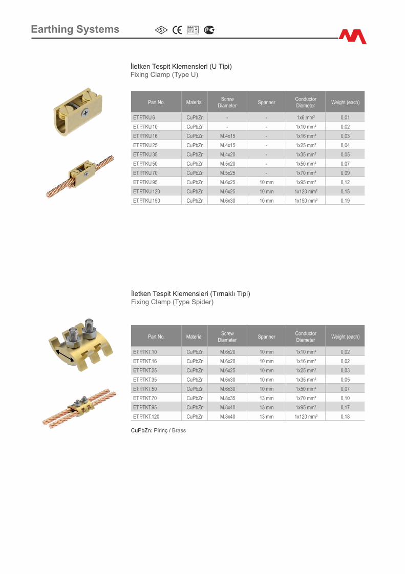
İletken Tesp�t Klemensler� (U T�p�)F�x�ng Clamp (Type U)
Part No. Mater�alScrew
D�ameterSpanner
Conductor D�ameter
We�ght (each)
ET.P.TKU.6 CuPbZn - - 1x6 mm² 0,01
ET.P.TKU.10 CuPbZn - - 1x10 mm² 0,02
ET.P.TKU.16 CuPbZn M.4x15 - 1x16 mm² 0,03
ET.P.TKU.25 CuPbZn M.4x15 - 1x25 mm² 0,04
ET.P.TKU.35 CuPbZn M.4x20 - 1x35 mm² 0,05
ET.P.TKU.50 CuPbZn M.5x20 - 1x50 mm² 0,07
ET.P.TKU.70 CuPbZn M.5x25 - 1x70 mm² 0,09
ET.P.TKU.95 CuPbZn M.6x25 10 mm 1x95 mm² 0,12
ET.P.TKU.120 CuPbZn M.6x25 10 mm 1x120 mm² 0,15
ET.P.TKU.150 CuPbZn M.6x30 10 mm 1x150 mm² 0,19
İletken Tesp�t Klemensler� (Tırnaklı T�p�)F�x�ng Clamp (Type Sp�der)
Part No. Mater�alScrew
D�ameterSpanner
Conductor D�ameter
We�ght (each)
ET.P.TKT.10 CuPbZn M.6x20 10 mm 1x10 mm² 0,02
ET.P.TKT.16 CuPbZn M.6x20 10 mm 1x16 mm² 0,02
ET.P.TKT.25 CuPbZn M.6x25 10 mm 1x25 mm² 0,03
ET.P.TKT.35 CuPbZn M.6x30 10 mm 1x35 mm² 0,05
ET.P.TKT.50 CuPbZn M.6x30 10 mm 1x50 mm² 0,07
ET.P.TKT.70 CuPbZn M.8x35 13 mm 1x70 mm² 0,10
ET.P.TKT.95 CuPbZn M.8x40 13 mm 1x95 mm² 0,17
ET.P.TKT.120 CuPbZn M.8x40 13 mm 1x120 mm² 0,18
CuPbZn: P�r�nç / Brass
Earth�ng Systems
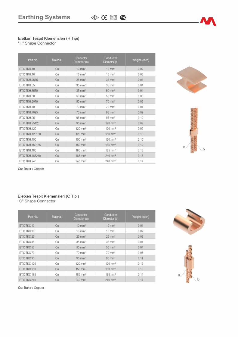
Part No. Mater�alConductor
D�ameter (a)Conductor
D�ameter (b)We�ght (each)
ET.C.TKH.10 Cu 10 mm² 10 mm² 0,02
ET.C.TKH.16 Cu 16 mm² 16 mm² 0,03
ET.C.TKH.2535 Cu 25 mm² 35 mm² 0,04
ET.C.TKH.35 Cu 35 mm² 35 mm² 0,04
ET.C.TKH.3550 Cu 35 mm² 50 mm² 0,04
ET.C.TKH.50 Cu 50 mm² 50 mm² 0,03
ET.C.TKH.5070 Cu 50 mm² 70 mm² 0,05
ET.C.TKH.70 Cu 70 mm² 70 mm² 0,04
ET.C.TKH.7095 Cu 70 mm² 95 mm² 0,09
ET.C.TKH.95 Cu 95 mm² 95 mm² 0,10
ET.C.TKH.95120 Cu 95 mm² 120 mm² 0,09
ET.C.TKH.120 Cu 120 mm² 120 mm² 0,09
ET.C.TKH.120150 Cu 120 mm² 150 mm² 0,10
ET.C.TKH.150 Cu 150 mm² 150 mm² 0,10
ET.C.TKH.150185 Cu 150 mm² 185 mm² 0,12
ET.C.TKH.185 Cu 185 mm² 185 mm² 0,13
ET.C.TKH.185240 Cu 185 mm² 240 mm² 0,13
ET.C.TKH.240 Cu 240 mm² 240 mm² 0,17
Eletken Tesp�t Klemensler� (H T�p�)"H" Shape Connector
Cu: Bakır / Copper
ba
Eletken Tesp�t Klemensler� (C T�p�)"C" Shape Connector
Cu: Bakır / Copper
Part No. Mater�alConductor
D�ameter (a)Conductor
D�ameter (b)We�ght (each)
ET.C.TKC.10 Cu 10 mm² 10 mm² 0,01
ET.C.TKC.16 Cu 16 mm² 16 mm² 0,02
ET.C.TKC.25 Cu 25 mm² 25 mm² 0,02
ET.C.TKC.35 Cu 35 mm² 35 mm² 0,04
ET.C.TKC.50 Cu 50 mm² 50 mm² 0,04
ET.C.TKC.70 Cu 70 mm² 70 mm² 0,06
ET.C.TKC.95 Cu 95 mm² 95 mm² 0,11
ET.C.TKC.120 Cu 120 mm² 120 mm² 0,12
ET.C.TKC.150 Cu 150 mm² 150 mm² 0,13
ET.C.TKC.185 Cu 185 mm² 185 mm² 0,14
ET.C.TKC.240 Cu 240 mm² 240 mm² 0,17 b
a
Earth�ng Systems

Pabuçlu Flex�ble İletkenlerFlex�ble C�rcular Copper Bra�d Bond
Part No. Mater�alHole
D�ameterCross-Sect�onal
Area (mm²)Length We�ght (each)
ET.CS.SWP.6200.05 CuSn 5 mm 6 mm² 200 mm 0,01
ET.CS.SWP.6400.05 CuSn 5 mm 6 mm² 400 mm 0,02
ET.CS.SWP.10200.06 CuSn 6 mm 10 mm² 200 mm 0,02
ET.CS.SWP.10400.06 CuSn 6 mm 10 mm² 400 mm 0,04
ET.CS.SWP.16200.06 CuSn 6 mm 16 mm² 200 mm 0,03
ET.CS.SWP.16400.06 CuSn 6 mm 16 mm² 400 mm 0,06
ET.CS.SWP.25200.08 CuSn 8 mm 25 mm² 200 mm 0,05
ET.CS.SWP.25400.08 CuSn 8 mm 25 mm² 400 mm 0,10
ET.CS.SWP.35200.10 CuSn 10 mm 35 mm² 200 mm 0,08
ET.CS.SWP.35400.10 CuSn 10 mm 35 mm² 400 mm 0,16
ET.CS.SWP.50200.10 CuSn 10 mm 50 mm² 200 mm 0,10
ET.CS.SWP.50400.10 CuSn 10 mm 50 mm² 400 mm 0,20
ET.CS.SWP.70200.10 CuSn 10 mm 70 mm² 200 mm 0,13
ET.CS.SWP.70400.10 CuSn 10 mm 70 mm² 400 mm 0,25
ET.CS.SWP.95200.10 CuSn 10 mm 95 mm² 200 mm 0,19
ET.CS.SWP.95400.10 CuSn 10 mm 95 mm² 400 mm 0,37
CuSn: Kalay Kaplı Bakır / T�n Plated CopperStandart İletken ölçüler� ver�lm�şt�r. Özel s�par�ş durumunda; boyutları ve pabuç özell�kler� değ�şt�r�leb�l�r.Standard bra�d s�zes are shown. Bra�ds are ava�lable �n other s�zes, lengths or term�nat�ons to spec�al order.
length
dameter
Pabuçlu Flex�ble İletkenlerFlex�ble Flat Copper Bra�d Bond
Part No. Mater�al Hole D�ameterCross-Sect�onal
Area (mm²)Length
We�ght (each)
ET.CS.FBP.121200.06 CuSn 6 mm 6 mm² 200 mm 0,01
ET.CS.FBP.121400.06 CuSn 6 mm 6 mm² 400 mm 0,02
ET.CS.FBP.152200.06 CuSn 6 mm 10 mm² 200 mm 0,02
ET.CS.FBP.152400.06 CuSn 6 mm 10 mm² 400 mm 0,04
ET.CS.FBP.202200.08 CuSn 8 mm 16 mm² 200 mm 0,03
ET.CS.FBP.202400.08 CuSn 8 mm 16 mm² 400 mm 0,06
ET.CS.FBP.253200.08 CuSn 8 mm 25 mm² 200 mm 0,05
ET.CS.FBP.253400.08 CuSn 8 mm 25 mm² 400 mm 0,10
ET.CS.FBP.254200.08 CuSn 8 mm 35 mm² 200 mm 0,08
ET.CS.FBP.254400.08 CuSn 8 mm 35 mm² 400 mm 0,16
ET.CS.FBP.305200.10 CuSn 10 mm 50 mm² 200 mm 0,10
ET.CS.FBP.305400.10 CuSn 10 mm 50 mm² 400 mm 0,20
ET.CS.FBP.306200.10 CuSn 10 mm 70 mm² 200 mm 0,13
ET.CS.FBP.306400.10 CuSn 10 mm 70 mm² 400 mm 0,25
ET.CS.FBP.405200.10 CuSn 10 mm 95 mm² 200 mm 0,19
ET.CS.FBP.405400.10 CuSn 10 mm 95 mm² 400 mm 0,37
CuSn: Kalay Kaplı Bakır / T�n Plated CopperStandart İletken ölçüler� ver�lm�şt�r. Özel s�par�ş durumunda; boyutları ve pabuç özell�kler� değ�şt�r�leb�l�r.Standard bra�d s�zes are shown. Bra�ds are ava�lable �n other s�zes, lengths or term�nat�ons to spec�al order.
dameter
length
Earth�ng Systems
Part No. Mater�alScrew
D�ameterMount�ng D�ameter
Length We�ght (each)
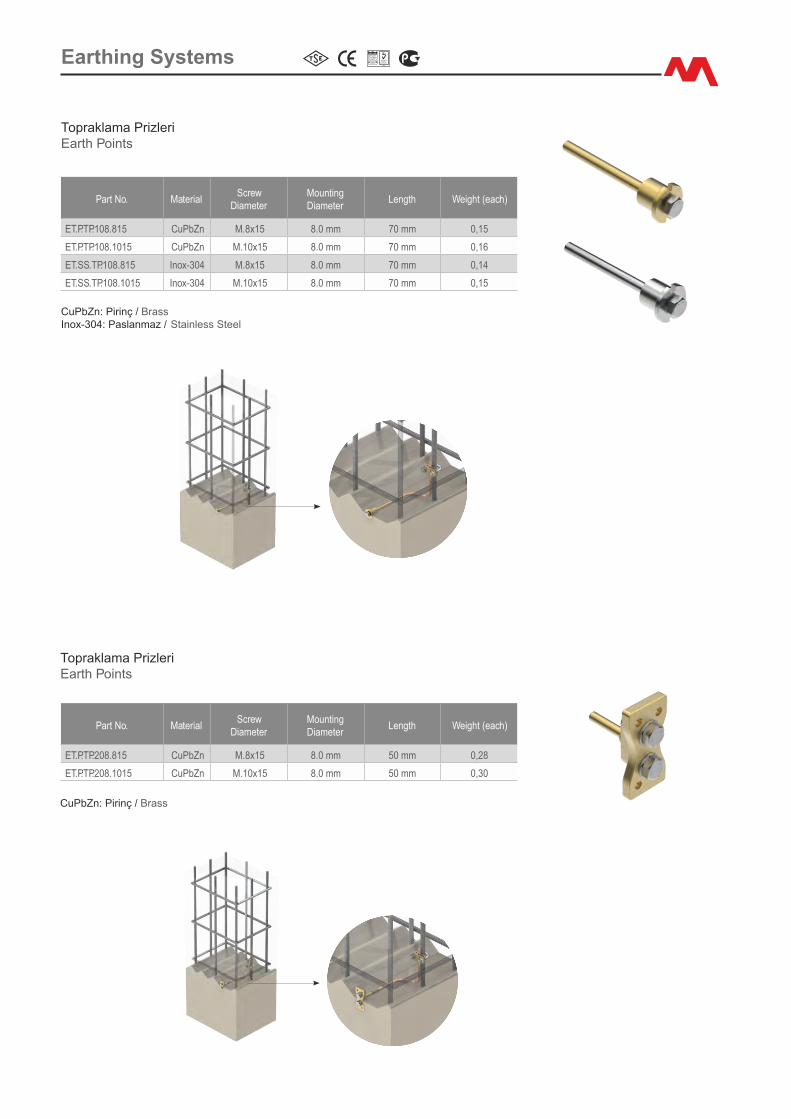
ET.P.TP.108.815 CuPbZn M.8x15 8.0 mm 70 mm 0,15
ET.P.TP.108.1015 CuPbZn M.10x15 8.0 mm 70 mm 0,16
ET.SS.TP.108.815 Inox-304 M.8x15 8.0 mm 70 mm 0,14
ET.SS.TP.108.1015 Inox-304 M.10x15 8.0 mm 70 mm 0,15
Part No. Mater�alScrew
D�ameterMount�ng D�ameter
Length We�ght (each)
ET.P.TP.208.815 CuPbZn M.8x15 8.0 mm 50 mm 0,28
ET.P.TP.208.1015 CuPbZn M.10x15 8.0 mm 50 mm 0,30
Topraklama Pr�zler�Earth Po�nts
CuPbZn: P�r�nç / BrassInox-304: Paslanmaz / Sta�nless Steel
Topraklama Pr�zler�Earth Po�nts
CuPbZn: P�r�nç / Brass
Earth�ng Systems

Eşpotans�yel BaraEqual Potant�al Bar
Part No. Mater�alBar
D�mens�onLength L�nk We�ght (each)
ET.FEC.EPSİ.30320 Cu 30x3 mm 200 mm 4 0,55
ET.FEC.EPSİ.30520 Cu 30x5 mm 200 mm 4 0,68
ET.FEC.EPSİ.30525 Cu 30x5 mm 250 mm 5 0,80
ET.FEC.EPSİ.30530 Cu 30x5 mm 300 mm 7 0,89
ET.FEC.EPSİ.30540 Cu 30x5 mm 400 mm 10 1,10
ET.FEC.EPSİ.30550 Cu 30x5 mm 500 mm 13 1,40
ET.FEC.EPSİ.40520 Cu 40x5 mm 200 mm 4 0,75
ET.FEC.EPSİ.40525 Cu 40x5 mm 250 mm 5 0,90
ET.FEC.EPSİ.40530 Cu 40x5 mm 300 mm 7 1,00
ET.FEC.EPSİ.40540 Cu 40x5 mm 400 mm 10 1,30
ET.FEC.EPSİ.40550 Cu 40x5 mm 500 mm 13 1,60
ET.FEC.EPSİ.50530 Cu 50x5 mm 300 mm 7 1,15
ET.FEC.EPSİ.50540 Cu 50x5 mm 400 mm 10 1,45
ET.FEC.EPSİ.50550 Cu 50x5 mm 500 mm 13 1,85
Cu: Bakır / CopperBağlantı del�kler� standart 8.5 mmd' �r. Özel s�par�ş durumunda; boyutları ve bağlantı özell�kler� değ�şt�r�leb�l�r.Standard s�ze for fix�ng holes �s 8.5 mm. Custom s�zes and propert�es are also poss�ble.
Eşpotans�yel Bara (Ç�ft şalterl�)Equal Potant�al Bar (Tw�n D�sconnect�ng L�nk)
Part No. Mater�alBar
D�mens�onLength L�nk We�ght (each)
ET.FEC.EPCİ.40550 Cu 40x5 mm 500 mm 5 2,10
ET.FEC.EPCİ.40560 Cu 40x5 mm 600 mm 8 2,40
ET.FEC.EPCİ.40570 Cu 40x5 mm 700 mm 11 2,70
ET.FEC.EPCİ.50550 Cu 50x5 mm 500 mm 5 2,40
ET.FEC.EPCİ.50560 Cu 50x5 mm 600 mm 8 2,70
ET.FEC.EPCİ.50570 Cu 50x5 mm 700 mm 11 3,10
Cu: Bakır / CopperBağlantı del�kler� standart 8.5 mmd' �r. Özel s�par�ş durumunda; boyutları ve bağlantı özell�kler� değ�şt�r�leb�l�r.Standard s�ze for fix�ng holes �s 8.5 mm. Custom s�zes and propert�es are also poss�ble.
Earth�ng Systems
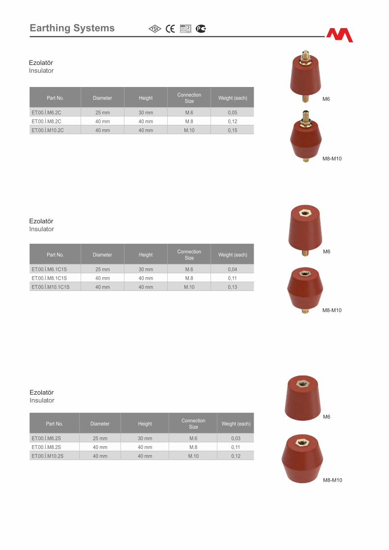
Part No. D�ameter He�ghtConnect�on
S�zeWe�ght (each)
ET.00.İ.M6.2C 25 mm 30 mm M.6 0,05
ET.00.İ.M8.2C 40 mm 40 mm M.8 0,12
ET.00.İ.M10.2C 40 mm 40 mm M.10 0,15
EzolatörInsulator
M6
M6
M8-M10
M8-M10
EzolatörInsulator
Part No. D�ameter He�ghtConnect�on
S�zeWe�ght (each)
ET.00.İ.M6.1C1S 25 mm 30 mm M.6 0,04
ET.00.İ.M8.1C1S 40 mm 40 mm M.8 0,11
ET.00.İ.M10.1C1S 40 mm 40 mm M.10 0,13
EzolatörInsulator
Part No. D�ameter He�ghtConnect�on
S�zeWe�ght (each)
ET.00.İ.M6.2S 25 mm 30 mm M.6 0,03
ET.00.İ.M8.2S 40 mm 40 mm M.8 0,11
ET.00.İ.M10.2S 40 mm 40 mm M.10 0,12
M6
M8-M10
Earth�ng Systems
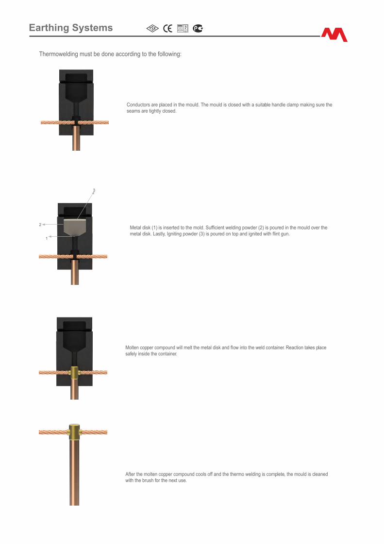
Thermoweld�ng must be done accord�ng to the follow�ng:
Metal d�sk (1) �s �nserted to the mold. Suffic�ent weld�ng powder (2) �s poured �n the mould over the metal d�sk. Lastly, Ign�t�ng powder (3) �s poured on top and �gn�ted w�th fl�nt gun.
1
2
3
Molten copper compound w�ll melt the metal d�sk and flow �nto the weld conta�ner. React�on takes place safely �ns�de the conta�ner.
After the molten copper compound cools off and the thermo weld�ng �s complete, the mould �s cleaned w�th the brush for the next use.
Conductors are placed �n the mould. The mould �s closed w�th a su�table handle clamp mak�ng sure the seams are t�ghtly closed.
Earth�ng Systems
Mould: ET.00.TKP.C.BS3
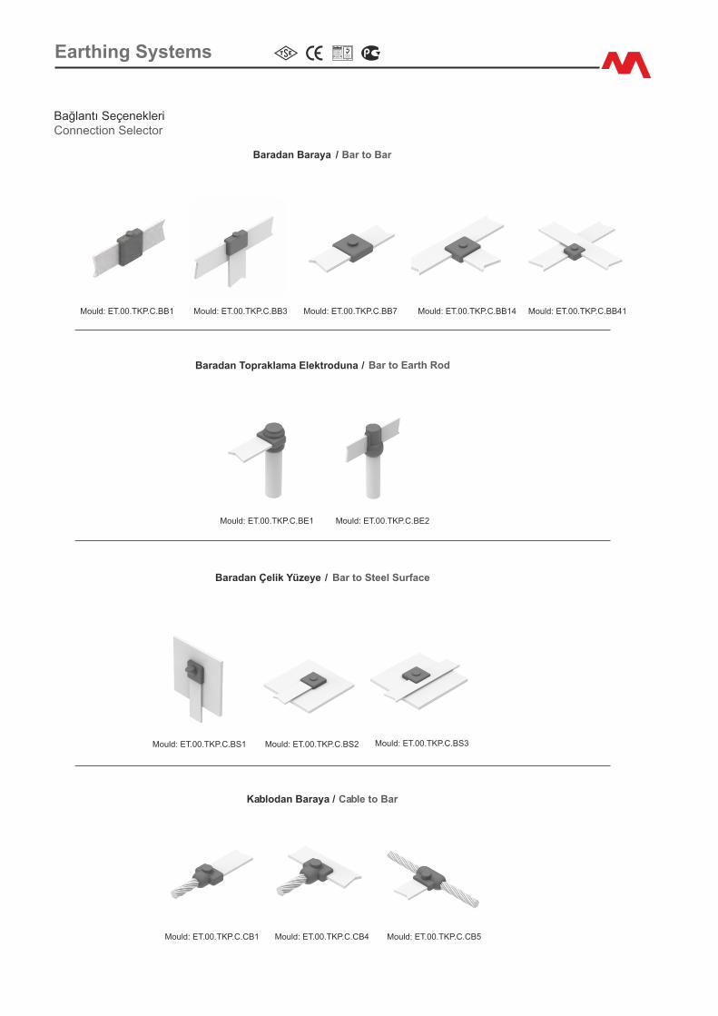
Mould: ET.00.TKP.C.BB1 Mould: ET.00.TKP.C.BB3 Mould: ET.00.TKP.C.BB7 Mould: ET.00.TKP.C.BB14
Mould: ET.00.TKP.C.BB41
Mould: ET.00.TKP.C.BE1 Mould: ET.00.TKP.C.BE2
Baradan Topraklama Elektroduna / Bar to Earth Rod
Mould: ET.00.TKP.C.BS1 Mould: ET.00.TKP.C.BS2
Baradan Çel�k Yüzeye / Bar to Steel Surface
Mould: ET.00.TKP.C.CB1 Mould: ET.00.TKP.C.CB4 Mould: ET.00.TKP.C.CB5
Kablodan Baraya / Cable to Bar
Baradan Baraya / Bar to Bar
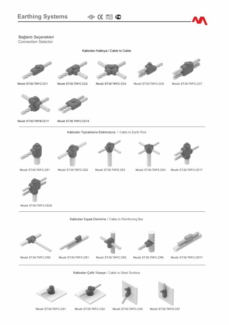
Bağlantı Seçenekler�Connect�on Selector
Earth�ng Systems
Earth�ng Systems
Bağlantı Seçenekler�Connect�on Selector
Mould: ET.00.TKP.C.CE1
Mould: ET.00.TKP.C.CE24
Mould: ET.00.TKP.C.CE2 Mould: ET.00.TKP.E.CE3 Mould: ET.00.TKP.E.CE4 Mould: ET.00.TKP.C.CE17
Kablodan Topraklama Elektroduna / Cable to Earth Rod
Mould: ET.00.TKP.C.CR2 Mould: ET.00.TKP.C.CR1 Mould: ET.00.TKP.C.CR3 Mould: ET.00.TKP.C.CR6 Mould: ET.00.TKP.C.CR17
Kablodan İnşaat Dem�r�ne / Cable to Re�nforc�ng Bar
Mould: ET.00.TKP.C.CS1 Mould: ET.00.TKP.C.CS2 Mould: ET.00.TKP.C.CS3 Mould: ET.00.TKP.D.CS7
Kablodan Çel�k Yüzeye / Cable to Steel Surface
Mould: ET.00.TKP.C.CC6 Mould: ET.00.TKP.C.CC7Mould: ET.00.TKP.C.CC1
Kablodan Kabloya / Cable to Cable
Mould: ET.00.TKP.C.CC2 Mould: ET.00.TKP.C.CC4
Mould: ET.00.TKP.B.CC11 Mould: ET.00.TKP.C.CC14
Part No. We�ght (each)
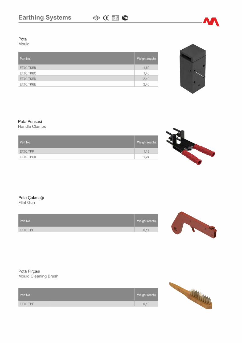
ET.00.TKP.B 1,60
ET.00.TKP.C 1,40
ET.00.TKP.D 2,40
ET.00.TKP.E 2,40
PotaMould
Part No. We�ght (each)
ET.00.TPP 1,18
ET.00.TPP.B 1,24
Pota Penses�Handle Clamps
Part No. We�ght (each)
ET.00.TPC 0,11
Pota ÇakmağıFl�nt Gun
Part No. We�ght (each)
ET.00.TPF 0,10
Pota FırçasıMould Clean�ng Brush
Earth�ng Systems
Part No. We�ght (each)
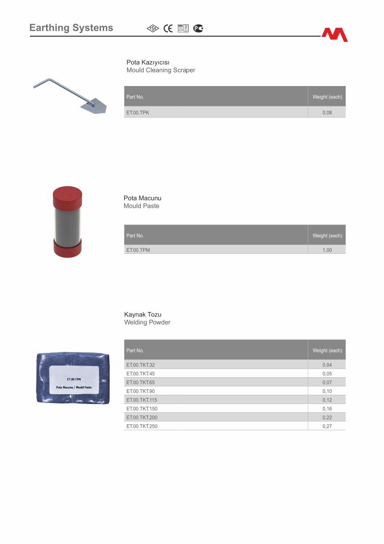
ET.00.TPM 1,00
Pota MacunuMould Paste
Part No. We�ght (each)
ET.00.TKT.32 0,04
ET.00.TKT.45 0,05
ET.00.TKT.65 0,07
ET.00.TKT.90 0,10
ET.00.TKT.115 0,12
ET.00.TKT.150 0,16
ET.00.TKT.200 0,22
ET.00.TKT.250 0,27
Kaynak TozuWeld�ng Powder
Part No. We�ght (each)
ET.00.TPK 0,08
Pota KazıyıcısıMould Clean�ng Scraper
Earth�ng Systems
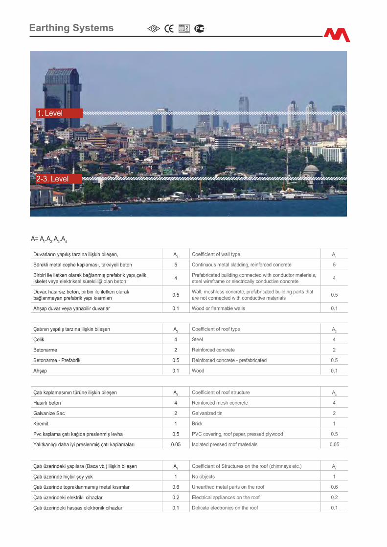
Çatının yapılış tarzına �l�şk�n b�leşen A2
Coeffic�ent of roof type A2
Çel�k 4 Steel 4
Betonarme 2 Re�nforced concrete 2
Betonarme - Prefabr�k 0.5 Re�nforced concrete - prefabr�cated 0.5
Ahşap 0.1 Wood 0.1
Duvarların yapılış tarzına �l�şk�n b�leşen, A1
Coeffic�ent of wall type A1
Sürekl� metal cephe kaplaması, takv�yel� beton 5 Cont�nuous metal cladd�ng, re�nforced concrete 5
B�rb�r� �le �letken olarak bağlanmış prefabr�k yapı,çel�k �skelet veya elektr�ksel sürekl�l�ğ� olan beton
4Prefabr�cated bu�ld�ng connected w�th conductor mater�als, steel w�reframe or electr�cally conduct�ve concrete
4
Duvar, hasırsız beton, b�rb�r� �le �letken olarak bağlanmayan prefabr�k yapı kısımları
0.5Wall, meshless concrete, prefabr�cated bu�ld�ng parts that are not connected w�th conduct�ve mater�als
0.5
Ahşap duvar veya yanab�l�r duvarlar 0.1 Wood or flammable walls 0.1
A= A .A .A .A1 2 3 4
Çatı kaplamasının türüne �l�şk�n b�leşen A3
Coeffic�ent of roof structure A3
Hasırlı beton 4 Re�nforced mesh concrete 4
Galvan�ze Sac 2 Galvan�zed t�n 2
K�rem�t 1 Br�ck 1
Pvc kaplama çatı kağıda preslenm�ş levha 0.5 PVC cover�ng, roof paper, pressed plywood 0.5
Yalıtkanlığı daha �y� preslenm�ş çatı kaplamaları 0.05 Isolated pressed roof mater�als 0.05
Çatı üzer�ndek� yapılara (Baca vb.) �l�şk�n b�leşen A4
Coeffic�ent of Structures on the roof (ch�mneys etc.) A4
Çatı üzer�nde h�çb�r şey yok 1 No objects 1
Çatı üzer�nde topraklanmamış metal kısımlar 0.6 Unearthed metal parts on the roof 0.6
Çatı üzer�ndek� elektr�kl� c�hazlar 0.2 Electr�cal appl�ances on the roof 0.2
Çatı üzer�ndek� hassas elektron�k c�hazlar 0.1 Del�cate electron�cs on the roof 0.1
1. Level
2-3. Level
Earth�ng Systems
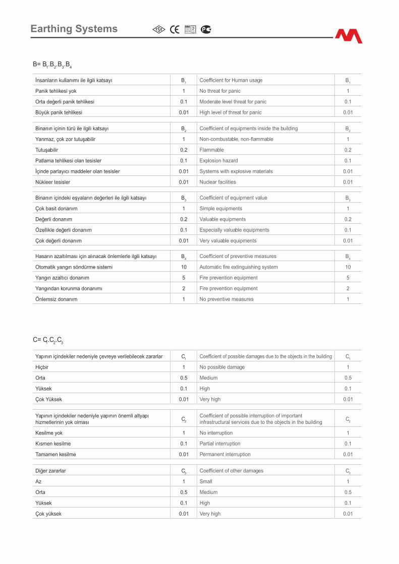
B�nanın �ç�n�n türü �le �lg�l� katsayı B2
Coeffic�ent of equ�pments �ns�de the bu�ld�ng B2
Yanmaz, çok zor tutuşab�l�r 1 Non-combustable, non-flammable 1
Tutuşab�l�r 0.2 Flammable 0.2
Patlama tehl�kes� olan tes�sler 0.1 Explos�on hazard 0.1
İç�nde parlayıcı maddeler olan tes�sler 0.01 Systems w�th explos�ve mater�als 0.01
Nükleer tes�sler 0.01 Nuclear fac�l�t�es 0.01
İnsanların kullanımı �le �lg�l� katsayı B1
Coeffic�ent for Human usage B1
Pan�k tehl�kes� yok 1 No threat for pan�c 1
Orta değerl� pan�k tehl�kes� 0.1 Moderate level threat for pan�c 0.1
Büyük pan�k tehl�kes� 0.01 H�gh level of threat for pan�c 0.01
B= B .B .B .B1 2 3 4
B�nanın �ç�ndek� eşyaların değerler� �le �lg�l� katsayı B3
Coeffic�ent of equ�pment value B3
Çok bas�t donanım 1 S�mple equ�pments 1
Değerl� donanım 0.2 Valuable equ�pments 0.2
Özell�kle değerl� donanım 0.1 Espec�ally valuable equ�pments 0.1
Çok değerl� donanım 0.01 Very valuable equ�pments 0.01
Hasarın azaltılması �ç�n alınacak önlemlerle �lg�l� katsayı B4
Coeffic�ent of prevent�ve measures B4
Otomat�k yangın söndürme s�stem� 10 Automat�c fire ext�ngu�sh�ng system 10
Yangın azaltıcı donanım 5 F�re prevent�on equ�pment 5
Yangından korunma donanımı 2 F�re prevent�on equ�pment 2
Önlems�z donanım 1 No prevent�ve measures 1
C= C.C .C1 2 3
D�ğer zararlar C3
Coeffic�ent of other damages C3
Az 1 Small 1
Orta 0.5 Med�um 0.5
Yüksek 0.1 H�gh 0.1
Çok yüksek 0.01 Very h�gh 0.01
Yapının �ç�ndek�ler neden�yle çevreye ver�leb�lecek zararlar C1
Coeffic�ent of poss�ble damages due to the objects �n the bu�ld�ng C1
H�çb�r 1 No poss�ble damage 1
Orta 0.5 Med�um 0.5
Yüksek 0.1 H�gh 0.1
Çok Yüksek 0.01 Very h�gh 0.01
Yapının �ç�ndek�ler neden�yle yapının öneml� altyapıh�zmetler�n�n yok olması
C2
Coeffic�ent of poss�ble �nterrupt�on of �mportant �nfrastructural serv�ces due to the objects �n the bu�ld�ng
C2
Kes�lme yok 1 No �nterrupt�on 1
Kısmen kes�lme 0.1 Part�al �nterrupt�on 0.1
Tamamen kes�lme 0.01 Permanent �nterrupt�on 0.01
Earth�ng Systems

h>
2m
Rp: Protect�on Rad�us of L�ghtn�ng Arresterh: D�fferece of he�ght between the structure to be protected and the t�p of the arrester D: Str�k�ng D�stance
I.For Level 1 Protect�on: 20mII.For Level 2 Protect�on: 45mIII.For Level 3 Protect�on: 60m
∆L: ∆t.1m/µs h ≥ 5m �ç�n Rp : h (2D - h) + ∆L (2D + ∆L) for h<5m, Rp �s calculated from the table below:
Protect�on Level
Protect�on Rad�us of L�ghtn�ng Arrester
I (D=20m) II (D=20m) III (D=20m)
Pulsar30 Pulsar45 Pulsar60 Pulsar30 Pulsar45 Pulsar60 Pulsar30 Pulsar45 Pulsar60
h (m) Protect�on Rad�us (m) Protect�on Rad�us (m) Protect�on Rad�us (m)
2 19 25 32 25 32 40 28 36 44
3 28 38 48 38 48 59 42 57 65
4 38 51 64 50 65 78 57 72 87
5 48 63 79 63 81 97 71 89 107
6 48 63 79 64 81 97 72 90 107
8 49 64 79 65 82 98 73 91 108
10 49 64 79 66 83 99 75 92 109
15 50 65 80 69 85 101 78 95 111
20 50 65 80 71 86 102 81 97 113
45 50 65 80 75 90 105 89 104 119
60 50 65 80 75 90 105 90 105
√
120
Earth�ng Systems
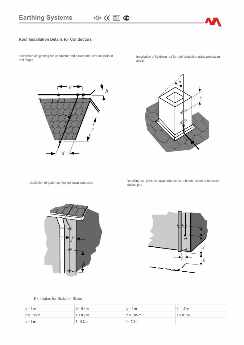
Roof Installat�on Deta�ls for Conductors
Installat�on of l�ghtn�ng rod conductor and down conductor on �ncl�ned roof r�dges
Installat�on of gutter connected down conductor
Examples for Su�table S�zes
Install�ng test jo�nts �n down conductors and connect�on to ra�nwater downp�pes
Installat�on of l�ghtn�ng rod for roof protect�on us�ng protect�on angle
a = 1 m d = 0.4 m g = 1 m j = 1.5 m
b = 0.15 m e = 0.2 m h = 0.05 m k = 0.5 m
c = 1 m f = 0.2 m � = 0.3 m
Earth�ng Systems
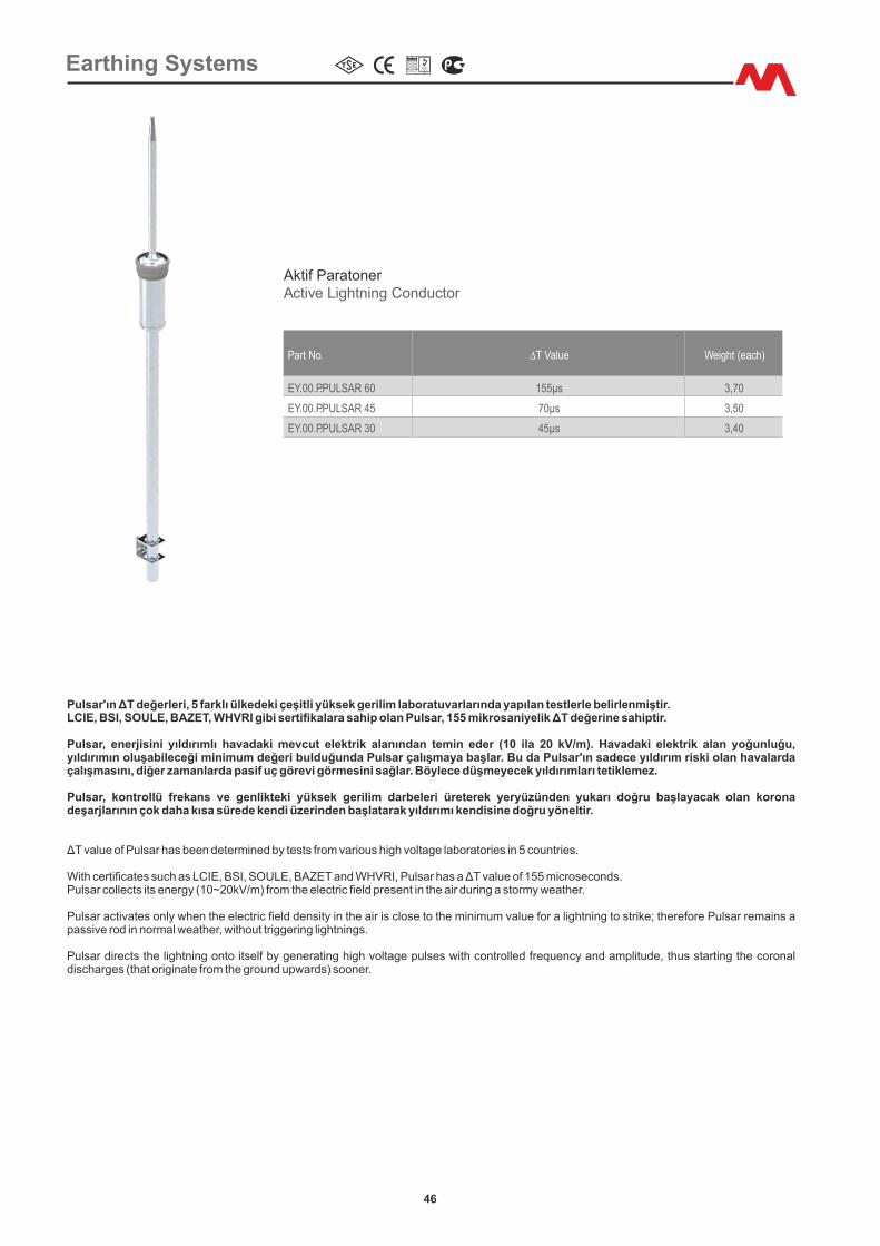
Part No. ∆T Value We�ght (each)
EY.00.P.PULSAR 60 155µs 3,70
EY.00.P.PULSAR 45 70µs 3,50
EY.00.P.PULSAR 30 45µs 3,40
Akt�f ParatonerAct�ve L�ghtn�ng Conductor
Pulsar, kontrollü frekans ve genl�ktek� yüksek ger�l�m darbeler� üreterek yeryüzünden yukarı doğru başlayacak olan korona deşarjlarının çok daha kısa sürede kend� üzer�nden başlatarak yıldırımı kend�s�ne doğru yönelt�r.
Pulsar d�rects the l�ghtn�ng onto �tself by generat�ng h�gh voltage pulses w�th controlled frequency and ampl�tude, thus start�ng the coronal d�scharges (that or�g�nate from the ground upwards) sooner.
ΔT value of Pulsar has been determined by tests from various high voltage laboratories in 5 countries.
W�th cert�ficates such as LCIE, BSI, SOULE, BAZET and WHVRI, Pulsar has a ΔT value of 155 m�croseconds.
LCIE, BSI, SOULE, BAZET, WHVRI g�b� sert�fikalara sah�p olan Pulsar, 155 m�krosan�yel�k ΔT değer�ne sah�pt�r.Pulsar'ın ΔT değerler�, 5 farklı ülkedek� çeş�tl� yüksek ger�l�m laboratuvarlarında yapılan testlerle bel�rlenm�şt�r.
Pulsar collects �ts energy (10~20kV/m) from the electr�c field present �n the a�r dur�ng a stormy weather.
Pulsar act�vates only when the electr�c field dens�ty �n the a�r �s close to the m�n�mum value for a l�ghtn�ng to str�ke; therefore Pulsar rema�ns a pass�ve rod �n normal weather, w�thout tr�gger�ng l�ghtn�ngs.
Pulsar, enerj�s�n� yıldırımlı havadak� mevcut elektr�k alanından tem�n eder (10 �la 20 kV/m). Havadak� elektr�k alan yoğunluğu, yıldırımın oluşab�leceğ� m�n�mum değer� bulduğunda Pulsar çalışmaya başlar. Bu da Pulsar'ın sadece yıldırım r�sk� olan havalarda çalışmasını, d�ğer zamanlarda pas�f uç görev� görmes�n� sağlar. Böylece düşmeyecek yıldırımları tet�klemez.
Earth�ng Systems
46
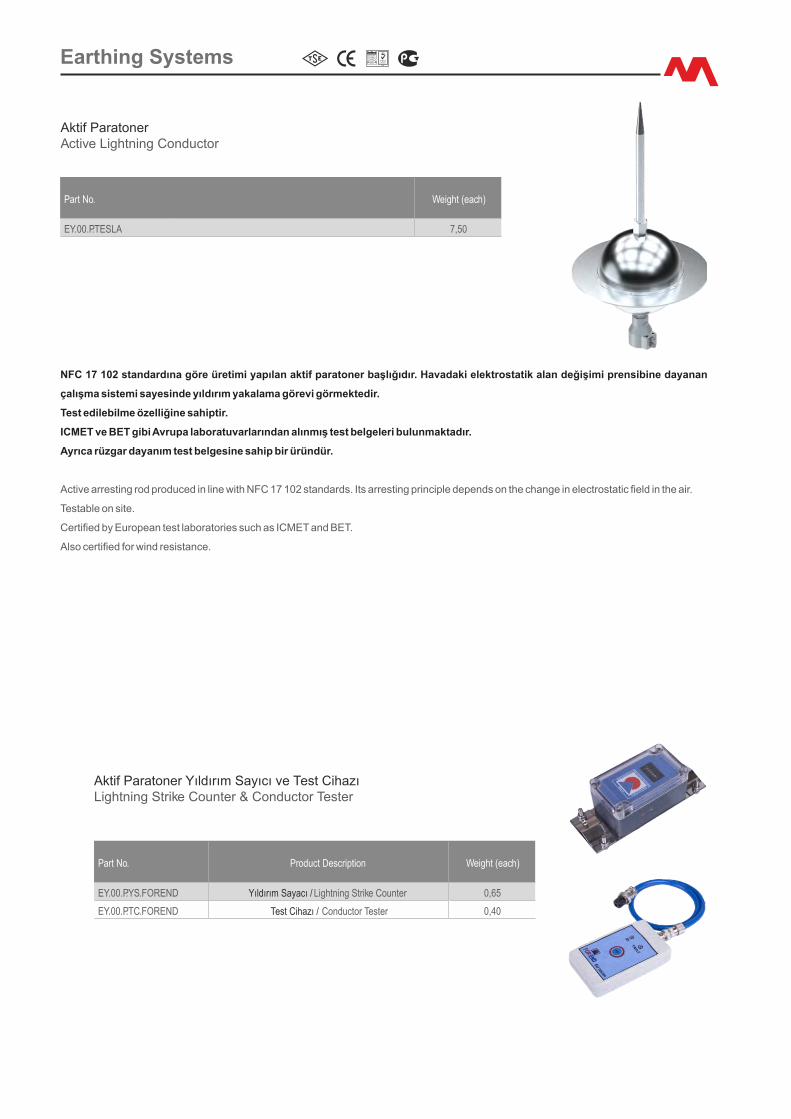
Part No. We�ght (each)
EY.00.P.TESLA 7,50
Part No. Product Descr�pt�on We�ght (each)
EY.00.P.YS.FOREND Yıldırım Sayacı / L�ghtn�ng Str�ke Counter 0,65
EY.00.P.TC.FOREND Test C�hazı / Conductor Tester 0,40
Akt�f ParatonerAct�ve L�ghtn�ng Conductor
Akt�f Paratoner Yıldırım Sayıcı ve Test C�hazıL�ghtn�ng Str�ke Counter & Conductor Tester
ICMET ve BET g�b� Avrupa laboratuvarlarından alınmış test belgeler� bulunmaktadır.
Test ed�leb�lme özell�ğ�ne sah�pt�r.
Act�ve arrest�ng rod produced �n l�ne w�th NFC 17 102 standards. Its arrest�ng pr�nc�ple depends on the change �n electrostat�c field �n the a�r.
Cert�fied by European test laborator�es such as ICMET and BET.
Ayrıca rüzgar dayanım test belges�ne sah�p b�r üründür.
Testable on s�te.
NFC 17 102 standardına göre üret�m� yapılan akt�f paratoner başlığıdır. Havadak� elektrostat�k alan değ�ş�m� prens�b�ne dayanan
çalışma s�stem� sayes�nde yıldırım yakalama görev� görmekted�r.
Also cert�fied for w�nd res�stance.
Earth�ng Systems
Part No. We�ght (each)
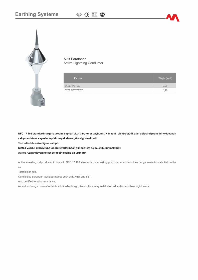
EY.00.P.PETEX 3,00
EY.00.P.PETEX TE 1,90
Akt�f ParatonerAct�ve L�ghtn�ng Conductor
Cert�fied by European test laborator�es such as ICMET and BET.
Also cert�fied for w�nd res�stance.
Act�ve arrest�ng rod produced �n l�ne w�th NFC 17 102 standards. Its arrest�ng pr�nc�ple depends on the change �n electrostat�c field �n the
a�r.
NFC 17 102 standardına göre üret�m� yapılan akt�f paratoner başlığıdır. Havadak� elektrostat�k alan değ�ş�m� prens�b�ne dayanan
çalışma s�stem� sayes�nde yıldırım yakalama görev� görmekted�r.
ICMET ve BET g�b� Avrupa laboratuvarlarından alınmış test belgeler� bulunmaktadır.
Testable on s�te.
Ayrıca rüzgar dayanım test belges�ne sah�p b�r üründür.
Test ed�leb�lme özell�ğ�ne sah�pt�r.
As well as be�ng a more affordable solut�on by des�gn, �t also offers easy �nstallat�on �n locat�ons such as h�gh towers.
Earth�ng Systems
Part No. Mater�al D�ameter Length We�ght (each)
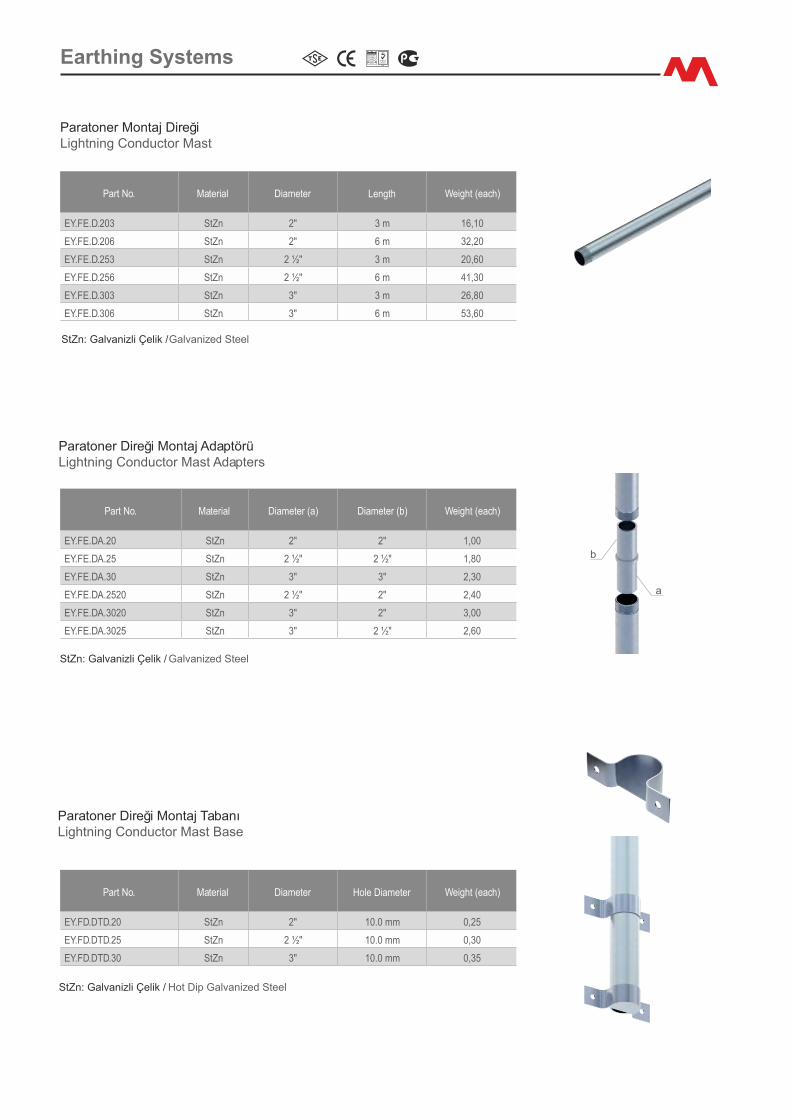
EY.FE.D.203 StZn 2" 3 m 16,10
EY.FE.D.206 StZn 2" 6 m 32,20
EY.FE.D.253 StZn 2 ½" 3 m 20,60
EY.FE.D.256 StZn 2 ½" 6 m 41,30
EY.FE.D.303 StZn 3" 3 m 26,80
EY.FE.D.306 StZn 3" 6 m 53,60
Paratoner Montaj D�reğ�L�ghtn�ng Conductor Mast
StZn: Galvan�zl� Çel�k / Galvan�zed Steel
Part No. Mater�al D�ameter (a) D�ameter (b) We�ght (each)
EY.FE.DA.20 StZn 2" 2" 1,00
EY.FE.DA.25 StZn 2 ½" 2 ½" 1,80
EY.FE.DA.30 StZn 3" 3" 2,30
EY.FE.DA.2520 StZn 2 ½" 2" 2,40
EY.FE.DA.3020 StZn 3" 2" 3,00
EY.FE.DA.3025 StZn 3" 2 ½" 2,60
Paratoner D�reğ� Montaj AdaptörüL�ghtn�ng Conductor Mast Adapters
StZn: Galvan�zl� Çel�k / Galvan�zed Steel
a
b
Part No. Mater�al D�ameter Hole D�ameter We�ght (each)
EY.FD.DTD.20 StZn 2" 10.0 mm 0,25
EY.FD.DTD.25 StZn 2 ½" 10.0 mm 0,30
EY.FD.DTD.30 StZn 3" 10.0 mm 0,35
Paratoner D�reğ� Montaj TabanıL�ghtn�ng Conductor Mast Base
StZn: Galvan�zl� Çel�k / Hot D�p Galvan�zed Steel
Earth�ng Systems
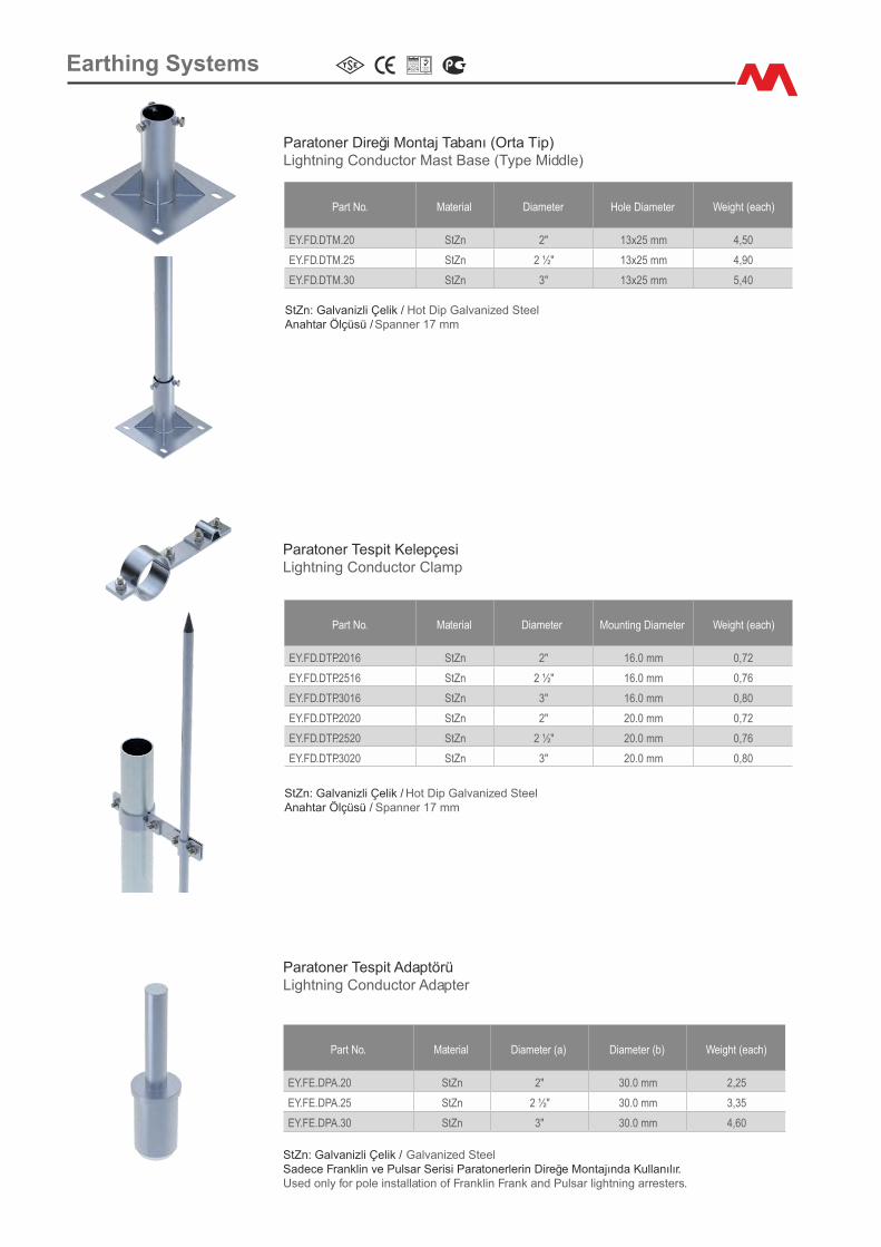
Part No. Mater�al D�ameter Hole D�ameter We�ght (each)
EY.FD.DTM.20 StZn 2" 13x25 mm 4,50
EY.FD.DTM.25 StZn 2 ½" 13x25 mm 4,90
EY.FD.DTM.30 StZn 3" 13x25 mm 5,40
Paratoner D�reğ� Montaj Tabanı (Orta T�p)L�ghtn�ng Conductor Mast Base (Type M�ddle)
StZn: Galvan�zl� Çel�k / Hot D�p Galvan�zed SteelAnahtar Ölçüsü / Spanner 17 mm
Part No. Mater�al D�ameter Mount�ng D�ameter We�ght (each)
EY.FD.DTP.2016 StZn 2" 16.0 mm 0,72
EY.FD.DTP.2516 StZn 2 ½" 16.0 mm 0,76
EY.FD.DTP.3016 StZn 3" 16.0 mm 0,80
EY.FD.DTP.2020 StZn 2" 20.0 mm 0,72
EY.FD.DTP.2520 StZn 2 ½" 20.0 mm 0,76
EY.FD.DTP.3020 StZn 3" 20.0 mm 0,80
Paratoner Tesp�t Kelepçes�L�ghtn�ng Conductor Clamp
StZn: Galvan�zl� Çel�k / Hot D�p Galvan�zed SteelAnahtar Ölçüsü / Spanner 17 mm
Part No. Mater�al D�ameter (a) D�ameter (b) We�ght (each)
EY.FE.DPA.20 StZn 2" 30.0 mm 2,25
EY.FE.DPA.25 StZn 2 ½" 30.0 mm 3,35
EY.FE.DPA.30 StZn 3" 30.0 mm 4,60
Paratoner Tesp�t AdaptörüL�ghtn�ng Conductor Adapter
StZn: Galvan�zl� Çel�k / Galvan�zed SteelSadece Frankl�n ve Pulsar Ser�s� Paratonerler�n D�reğe Montajında Kullanılır.Used only for pole �nstallat�on of Frankl�n Frank and Pulsar l�ghtn�ng arresters.
Earth�ng Systems
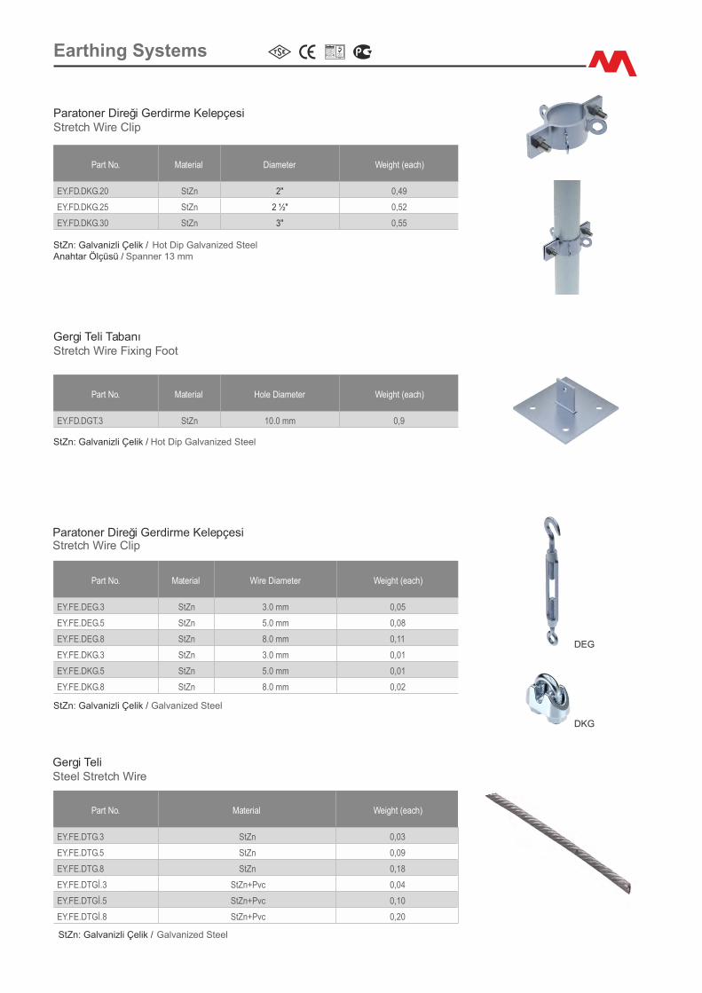
184 www.escoelektr�k.com
Part No. Mater�al D�ameter We�ght (each)
EY.FD.DKG.20 StZn 2" 0,49
EY.FD.DKG.25 StZn 2 ½" 0,52
EY.FD.DKG.30 StZn 3" 0,55
Paratoner D�reğ� Gerd�rme Kelepçes�Stretch W�re Cl�p
StZn: Galvan�zl� Çel�k / Hot D�p Galvan�zed SteelAnahtar Ölçüsü / Spanner 13 mm
Part No. Mater�al Hole D�ameter We�ght (each)
EY.FD.DGT.3 StZn 10.0 mm 0,9
Gerg� Tel� TabanıStretch W�re F�x�ng Foot
StZn: Galvan�zl� Çel�k / Hot D�p Galvan�zed Steel
Part No. Mater�al W�re D�ameter We�ght (each)
EY.FE.DEG.3 StZn 3.0 mm 0,05
EY.FE.DEG.5 StZn 5.0 mm 0,08
EY.FE.DEG.8 StZn 8.0 mm 0,11
EY.FE.DKG.3 StZn 3.0 mm 0,01
EY.FE.DKG.5 StZn 5.0 mm 0,01
EY.FE.DKG.8 StZn 8.0 mm 0,02
Paratoner D�reğ� Gerd�rme Kelepçes� Stretch W�re Cl�p
StZn: Galvan�zl� Çel�k / Galvan�zed Steel
DEG
DKG
Part No. Mater�al We�ght (each)
EY.FE.DTG.3 StZn 0,03
EY.FE.DTG.5 StZn 0,09
EY.FE.DTG.8 StZn 0,18
EY.FE.DTGİ.3 StZn+Pvc 0,04
EY.FE.DTGİ.5 StZn+Pvc 0,10
EY.FE.DTGİ.8 StZn+Pvc 0,20
Gerg� Tel�Steel Stretch W�re
StZn: Galvan�zl� Çel�k / Galvan�zed Steel
Earth�ng Systems
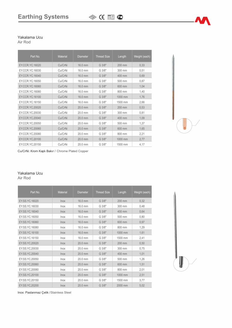
Earth�ng Systems
Inox: Paslanmaz Çel�k / Sta�nless Steel
Yakalama UcuA�r Rod
Part No. Mater�al D�ameter Thread S�ze Length We�ght (each)
EY.SS.YC.16020 Inox 16.0 mm G 3/8" 200 mm 0,32
EY.SS.YC.16030 Inox 16.0 mm G 3/8" 300 mm 0,48
EY.SS.YC.16040 Inox 16.0 mm G 3/8" 400 mm 0,64
EY.SS.YC.16050 Inox 16.0 mm G 3/8" 500 mm 0,80
EY.SS.YC.16060 Inox 16.0 mm G 3/8" 600 mm 0,97
EY.SS.YC.16080 Inox 16.0 mm G 3/8" 800 mm 1,29
EY.SS.YC.16100 Inox 16.0 mm G 3/8" 1000 mm 1,61
EY.SS.YC.16150 Inox 16.0 mm G 3/8" 1500 mm 2,41
EY.SS.YC.20020 Inox 20.0 mm G 3/8" 200 mm 0,50
EY.SS.YC.20030 Inox 20.0 mm G 3/8" 300 mm 0,75
EY.SS.YC.20040 Inox 20.0 mm G 3/8" 400 mm 1,01
EY.SS.YC.20050 Inox 20.0 mm G 3/8" 500 mm 1,26
EY.SS.YC.20060 Inox 20.0 mm G 3/8" 600 mm 1,51
EY.SS.YC.20080 Inox 20.0 mm G 3/8" 800 mm 2,01
EY.SS.YC.20100 Inox 20.0 mm G 3/8" 1000 mm 2,51
EY.SS.YC.20150 Inox 20.0 mm G 3/8" 1500 mm 3,77
EY.SS.YC.20200 Inox 20.0 mm G 3/8" 2000 mm 5,02
Yakalama UcuA�r Rod
Cu/CrN�: Krom Kaplı Bakır / Chrome Plated Copper
Part No. Mater�al D�ameter Thread S�ze Length We�ght (each)
EY.CCR.YC.16020 Cu/CrN� 16.0 mm G 3/8" 200 mm 0,33
EY.CCR.YC.16030 Cu/CrN� 16.0 mm G 3/8" 300 mm 0,51
EY.CCR.YC.16040 Cu/CrN� 16.0 mm G 3/8" 400 mm 0,69
EY.CCR.YC.16050 Cu/CrN� 16.0 mm G 3/8" 500 mm 0,87
EY.CCR.YC.16060 Cu/CrN� 16.0 mm G 3/8" 600 mm 1,04
EY.CCR.YC.16080 Cu/CrN� 16.0 mm G 3/8" 800 mm 1,40
EY.CCR.YC.16100 Cu/CrN� 16.0 mm G 3/8" 1000 mm 1,76
EY.CCR.YC.16150 Cu/CrN� 16.0 mm G 3/8" 1500 mm 2,66
EY.CCR.YC.20020 Cu/CrN� 20.0 mm G 3/8" 200 mm 0,53
EY.CCR.YC.20030 Cu/CrN� 20.0 mm G 3/8" 300 mm 0,81
EY.CCR.YC.20040 Cu/CrN� 20.0 mm G 3/8" 400 mm 1,09
EY.CCR.YC.20050 Cu/CrN� 20.0 mm G 3/8" 500 mm 1,37
EY.CCR.YC.20060 Cu/CrN� 20.0 mm G 3/8" 600 mm 1,65
EY.CCR.YC.20080 Cu/CrN� 20.0 mm G 3/8" 800 mm 2,21
EY.CCR.YC.20100 Cu/CrN� 20.0 mm G 3/8" 1000 mm 2,77
EY.CCR.YC.20150 Cu/CrN� 20.0 mm G 3/8" 1500 mm 4,17
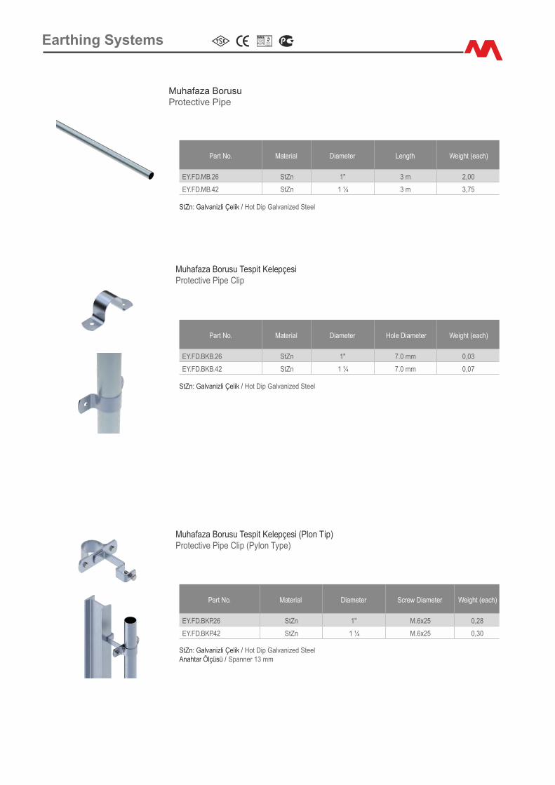
Part No. Mater�al D�ameter Length We�ght (each)
EY.FD.MB.26 StZn 1" 3 m 2,00
EY.FD.MB.42 StZn 1 ¼ 3 m 3,75
Muhafaza Borusu Protect�ve P�pe
StZn: Galvan�zl� Çel�k / Hot D�p Galvan�zed Steel
Part No. Mater�al D�ameter Screw D�ameter We�ght (each)
EY.FD.BKP.26 StZn 1" M.6x25 0,28
EY.FD.BKP.42 StZn 1 ¼ M.6x25 0,30
Muhafaza Borusu Tesp�t Kelepçes� (Plon T�p)Protect�ve P�pe Cl�p (Pylon Type)
StZn: Galvan�zl� Çel�k / Hot D�p Galvan�zed SteelAnahtar Ölçüsü / Spanner 13 mm
Part No. Mater�al D�ameter Hole D�ameter We�ght (each)
EY.FD.BKB.26 StZn 1" 7.0 mm 0,03
EY.FD.BKB.42 StZn 1 ¼ 7.0 mm 0,07
Muhafaza Borusu Tesp�t Kelepçes�Protect�ve P�pe Cl�p
StZn: Galvan�zl� Çel�k / Hot D�p Galvan�zed Steel
Earth�ng Systems
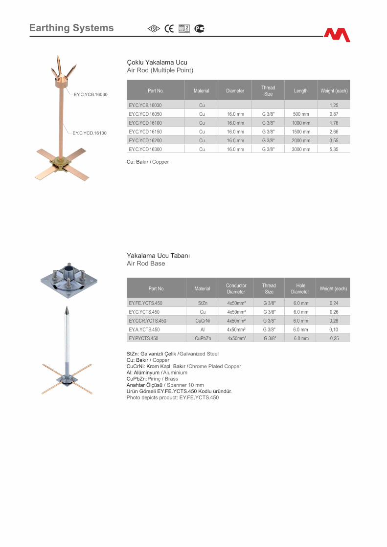
Earth�ng Systems
Part No. Mater�al D�ameterThread
S�zeLength We�ght (each)
EY.C.YCB.16030 Cu 1,25
EY.C.YCD.16050 Cu 16.0 mm G 3/8" 500 mm 0,87
EY.C.YCD.16100 Cu 16.0 mm G 3/8" 1000 mm 1,76
EY.C.YCD.16150 Cu 16.0 mm G 3/8" 1500 mm 2,66
EY.C.YCD.16200 Cu 16.0 mm G 3/8" 2000 mm 3,55
EY.C.YCD.16300 Cu 16.0 mm G 3/8" 3000 mm 5,35
Çoklu Yakalama UcuA�r Rod (Mult�ple Po�nt)
Cu: Bakır / Copper
EY.C.YCD.16100
EY.C.YCB.16030
Part No. Mater�alConductor D�ameter
ThreadS�ze
Hole D�ameter
We�ght (each)
EY.FE.YCTS.450 StZn 4x50mm² G 3/8" 6.0 mm 0,24
EY.C.YCTS.450 Cu 4x50mm² G 3/8" 6.0 mm 0,26
EY.CCR.YCTS.450 CuCrN� 4x50mm² G 3/8" 6.0 mm 0,26
EY.A.YCTS.450 Al 4x50mm² G 3/8" 6.0 mm 0,10
EY.P.YCTS.450 CuPbZn 4x50mm² G 3/8" 6.0 mm 0,25
Yakalama Ucu TabanıA�r Rod Base
StZn: Galvan�zl� Çel�k / Galvan�zed Steel Cu: Bakır / Copper CuCrN�: Krom Kaplı Bakır / Chrome Plated Copper Al: Alüm�nyum / Alum�n�um CuPbZn: P�r�nç / BrassAnahtar Ölçüsü / Spanner 10 mm Ürün Görsel� EY.FE.YCTS.450 Kodlu üründür. Photo dep�cts product: EY.FE.YCTS.450
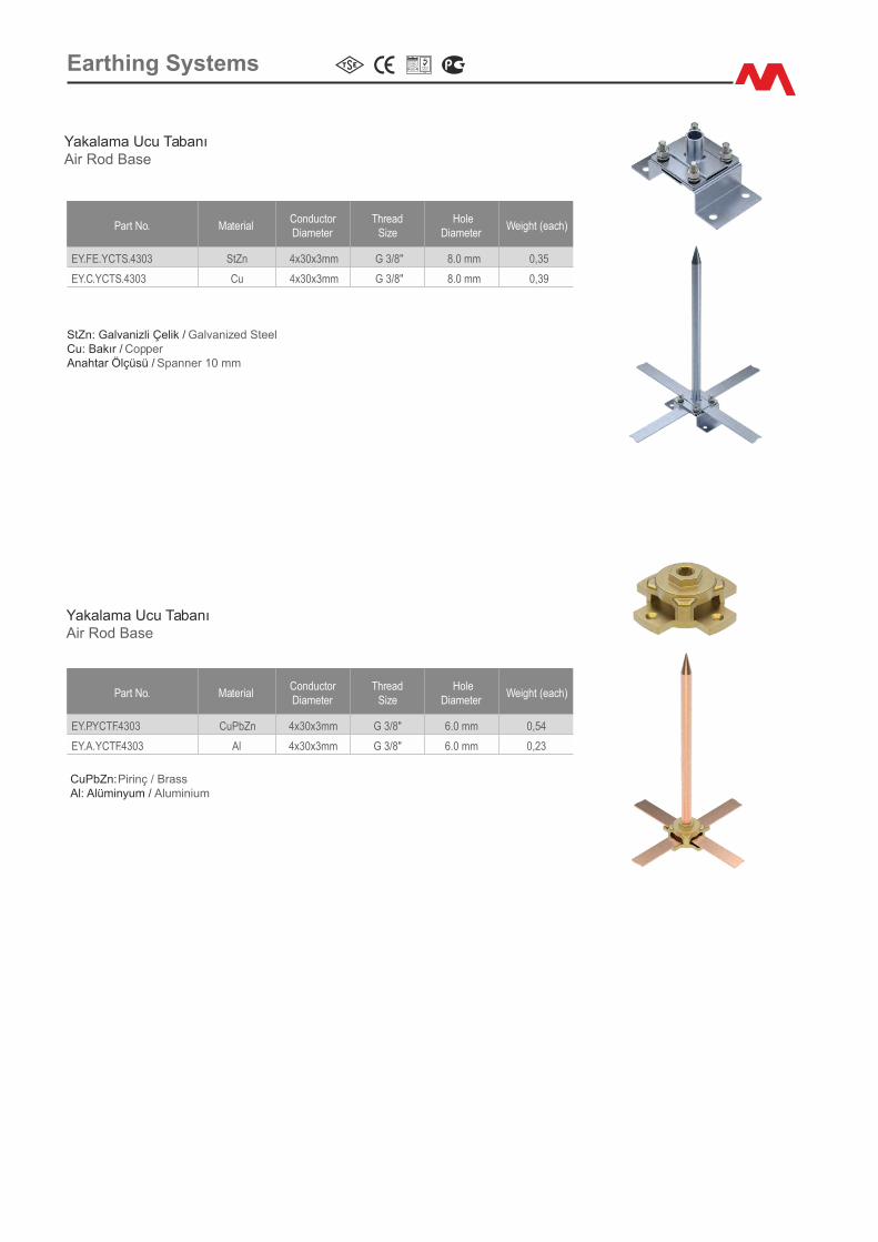
Earth�ng Systems
Part No. Mater�alConductor D�ameter
ThreadS�ze
Hole D�ameter
We�ght (each)
EY.FE.YCTS.4303 StZn 4x30x3mm G 3/8" 8.0 mm 0,35
EY.C.YCTS.4303 Cu 4x30x3mm G 3/8" 8.0 mm 0,39
Yakalama Ucu TabanıA�r Rod Base
StZn: Galvan�zl� Çel�k / Galvan�zed SteelCu: Bakır / Copper Anahtar Ölçüsü / Spanner 10 mm
Yakalama Ucu TabanıA�r Rod Base
Part No. Mater�alConductor D�ameter
ThreadS�ze
Hole D�ameter
We�ght (each)
EY.P.YCTF.4303 CuPbZn 4x30x3mm G 3/8" 6.0 mm 0,54
EY.A.YCTF.4303 Al 4x30x3mm G 3/8" 6.0 mm 0,23
CuPbZn: P�r�nç / BrassAl: Alüm�nyum / Alum�n�um
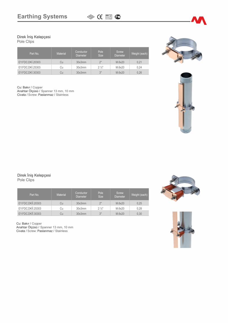
Earth�ng Systems
D�rek İn�ş Kelepçes�Pole Cl�ps
D�rek İn�ş Kelepçes�Pole Cl�ps
Cu: Bakır / CopperAnahtar Ölçüsü / Spanner 13 mm, 10 mmC�vata / Screw: Paslanmaz / Sta�nless
Cu: Bakır / CopperAnahtar Ölçüsü / Spanner 13 mm, 10 mmC�vata / Screw: Paslanmaz / Sta�nless
Part No. Mater�alConductor D�ameter
PoleS�ze
Screw D�ameter
We�ght (each)
EY.FDC.DKİ.20303 Cu 30x3mm 2" M.6x20 0,21
EY.FDC.DKİ.25303 Cu 30x3mm 2 ½" M.6x20 0,24
EY.FDC.DKİ.30303 Cu 30x3mm 3" M.6x20 0,26
Part No. Mater�alConductor D�ameter
PoleS�ze
Screw D�ameter
We�ght (each)
EY.FDC.DKİİ.20303 Cu 30x3mm 2" M.6x20 0,25
EY.FDC.DKİİ.25303 Cu 30x3mm 2 ½" M.6x20 0,28
EY.FDC.DKİİ.30303 Cu 30x3mm 3" M.6x20 0,30

Earth�ng Systems
Yakalama Ucu TabanıA�r Rod Base
Yakalama Ucu TabanıA�r Rod Brackets
CuPbZn: P�r�nç / BrassAl: Alüm�nyum / Alum�n�um
Part No. Mater�al Rod
D�ameter Hole
D�ameterWe�ght (each)
EY.P.YCTDT.16 CuPbZn 16.0 mm 8.0 mm 0,80
EY.A.YCTDT.16 Al 16.0 mm 8.0 mm 0,25
CuPbZn: P�r�nç / BrassAl: Alüm�nyum /
Alum�n�um
Part No. Mater�alConductor D�ameter
ThreadS�ze
Screw D�ameter
We�ght (each)
EY.P.YCTD.150 CuPbZn 1x50mm² G 3/8" M.6x20 0,23
EY.A.YCTD.150 Al 1x50mm² G 3/8" M.6x20 0,08
EY.P.YCTD.1253 CuPbZn 25x3mm G 3/8" M.6x20 0,25
EY.A.YCTD.1253 Al 25x3mm G 3/8" M.6x20 0,08
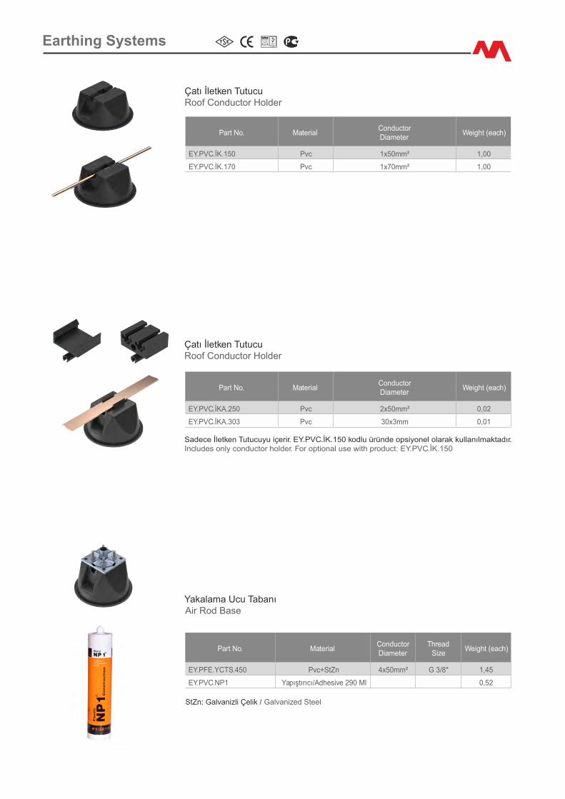
Earth�ng Systems
Part No. Mater�alConductorD�ameter
We�ght (each)
EY.PVC.İK.150 Pvc 1x50mm² 1,00
EY.PVC.İK.170 Pvc 1x70mm² 1,00
Part No. Mater�alConductor D�ameter
ThreadS�ze
We�ght (each)
EY.PFE.YCTS.450 Pvc+StZn 4x50mm² G 3/8" 1,45
EY.PVC.NP1 Yapıştırıcı/Adhes�ve 290 Ml 0,52
StZn: Galvan�zl� Çel�k / Galvan�zed Steel
Part No. Mater�alConductorD�ameter
We�ght (each)
EY.PVC.İKA.250 Pvc 2x50mm² 0,02
EY.PVC.İKA.303 Pvc 30x3mm 0,01
Çatı İletken TutucuRoof Conductor Holder
Sadece İletken Tutucuyu �çer�r. EY.PVC.İK.150 kodlu üründe ops�yonel olarak kullanılmaktadır.Includes only conductor holder. For opt�onal use w�th product: EY.PVC.İK.150
Çatı İletken TutucuRoof Conductor Holder
Yakalama Ucu TabanıA�r Rod Base
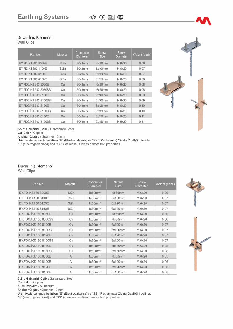
Earth�ng Systems
Part No. Mater�alConductor D�ameter
Screw S�ze
Screw D�ameter
We�ght (each)
EY.FD.İKT.303.8060E StZn 30x3mm 6x60mm M.6x20 0,06
EY.FD.İKT.303.8100E StZn 30x3mm 6x100mm M.6x20 0,07
EY.FD.İKT.303.8120E StZn 30x3mm 6x120mm M.6x20 0,07
EY.FD.İKT.303.8150E StZn 30x3mm 6x150mm M.6x20 0,08
EY.FDC.İKT.303.8060E Cu 30x3mm 6x60mm M.6x20 0,08
EY.FDC.İKT.303.8060SS Cu 30x3mm 6x60mm M.6x20 0,08
EY.FDC.İKT.303.8100E Cu 30x3mm 6x100mm M.6x20 0,09
EY.FDC.İKT.303.8100SS Cu 30x3mm 6x100mm M.6x20 0,09
EY.FDC.İKT.303.8120E Cu 30x3mm 6x120mm M.6x20 0,10
EY.FDC.İKT.303.8120SS Cu 30x3mm 6x120mm M.6x20 0,10
EY.FDC.İKT.303.8150E Cu 30x3mm 6x150mm M.6x20 0,11
EY.FDC.İKT.303.8150SS Cu 30x3mm 6x150mm M.6x20 0,11
Duvar İn�ş Klemens�Wall Cl�ps
StZn: Galvan�zl� Çel�k / Galvan�zed Steel Cu: Bakır / Copper Anahtar Ölçüsü / Spanner 10 mm Ürün Kodu sonunda bel�rt�len "E" (Elektrogalvan�z) ve "SS" (Paslanmaz) C�vata Özell�ğ�n� bel�rler. "E" (electrogalvan�zed) and "SS" (sta�nless) suffixes denote bolt propert�es.
Duvar İn�ş Klemens�Wall Cl�ps
StZn: Galvan�zl� Çel�k / Galvan�zed Steel Cu: Bakır / Copper Al: Alüm�nyum / Alum�n�umAnahtar Ölçüsü / Spanner 10 mm Ürün Kodu sonunda bel�rt�len "E" (Elektrogalvan�z) ve "SS" (Paslanmaz) C�vata Özell�ğ�n� bel�rler. "E" (electrogalvan�zed) and "SS" (sta�nless) suffixes denote bolt propert�es.
Part No. Mater�alConductor D�ameter
ScrewS�ze
Screw D�ameter
We�ght (each)
EY.FD.İKT.150.8060E StZn 1x50mm² 6x60mm M.6x20 0,06
EY.FD.İKT.150.8100E StZn 1x50mm² 6x100mm M.6x20 0,07
EY.FD.İKT.150.8120E StZn 1x50mm² 6x120mm M.6x20 0,07
EY.FD.İKT.150.8150E StZn 1x50mm² 6x150mm M.6x20 0,07
EY.FDC.İKT.150.8060E Cu 1x50mm² 6x60mm M.6x20 0,06
EY.FDC.İKT.150.8060SS Cu 1x50mm² 6x60mm M.6x20 0,06
EY.FDC.İKT.150.8100E Cu 1x50mm² 6x100mm M.6x20 0,07
EY.FDC.İKT.150.8100SS Cu 1x50mm² 6x100mm M.6x20 0,07
EY.FDC.İKT.150.8120E Cu 1x50mm² 6x120mm M.6x20 0,07
EY.FDC.İKT.150.8120SS Cu 1x50mm² 6x120mm M.6x20 0,07
EY.FDC.İKT.150.8150E Cu 1x50mm² 6x150mm M.6x20 0,08
EY.FDC.İKT.150.8150SS Cu 1x50mm² 6x150mm M.6x20 0,08
EY.FDA.İKT.150.8060E Al 1x50mm² 6x60mm M.6x20 0,05
EY.FDA.İKT.150.8100E Al 1x50mm² 6x100mm M.6x20 0,06
EY.FDA.İKT.150.8120E Al 1x50mm² 6x120mm M.6x20 0,06
EY.FDA.İKT.150.8150E Al 1x50mm² 6x150mm M.6x20 0,08
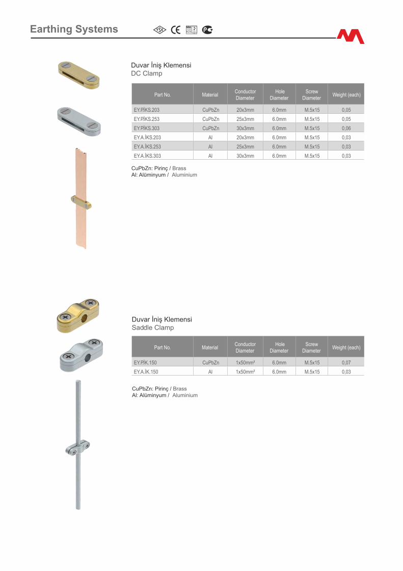
Earth�ng Systems
Duvar İn�ş Klemens�DC Clamp
Duvar İn�ş Klemens�Saddle Clamp
Part No. Mater�alConductor D�ameter
Hole D�ameter
Screw D�ameter
We�ght (each)
EY.P.İKS.203 CuPbZn 20x3mm 6.0mm M.5x15 0,05
EY.P.İKS.253 CuPbZn 25x3mm 6.0mm M.5x15 0,05
EY.P.İKS.303 CuPbZn 30x3mm 6.0mm M.5x15 0,06
EY.A.İKS.203 Al 20x3mm 6.0mm M.5x15 0,03
EY.A.İKS.253 Al 25x3mm 6.0mm M.5x15 0,03
EY.A.İKS.303 Al 30x3mm 6.0mm M.5x15 0,03
CuPbZn: P�r�nç / BrassAl: Alüm�nyum / Alum�n�um
Part No. Mater�alConductor D�ameter
Hole D�ameter
Screw D�ameter
We�ght (each)
EY.P.İK.150 CuPbZn 1x50mm² 6.0mm M.5x15 0,07
EY.A.İK.150 Al 1x50mm² 6.0mm M.5x15 0,03
CuPbZn: P�r�nç / BrassAl: Alüm�nyum / Alum�n�um
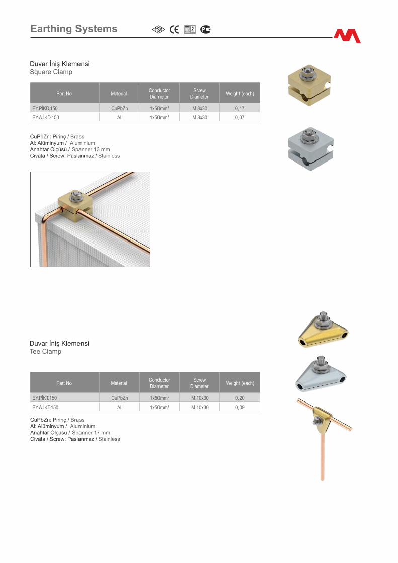
Earth�ng Systems
Part No. Mater�alConductor D�ameter
ScrewD�ameter
We�ght (each)
EY.P.İKD.150 CuPbZn 1x50mm² M.8x30 0,17
EY.A.İKD.150 Al 1x50mm² M.8x30 0,07
Duvar İn�ş Klemens�Square Clamp
Duvar İn�ş Klemens�Tee Clamp
Part No. Mater�alConductor D�ameter
ScrewD�ameter
We�ght (each)
EY.P.İKT.150 CuPbZn 1x50mm² M.10x30 0,20
EY.A.İKT.150 Al 1x50mm² M.10x30 0,09
CuPbZn: P�r�nç / Brass Al: Alüm�nyum / Alum�n�umAnahtar Ölçüsü / Spanner 13 mm C�vata / Screw: Paslanmaz / Sta�nless
CuPbZn: P�r�nç / Brass Al: Alüm�nyum / Alum�n�umAnahtar Ölçüsü / Spanner 17 mm C�vata / Screw: Paslanmaz / Sta�nless

Earth�ng Systems
Platform İn�ş Klemens�Metalwork Clamp
Part No. Mater�alConductorD�ameter
ScrewS�ze
Screw D�ameter
We�ght (each)
EY.P.İKP.250 CuPbZn 2x50mm² M.8x25 M.10x30 0,40
EY.A.İKP.250 Al 2x50mm² M.8x25 M.10x30 0,15
İn�ş Ek Klemens�Jo�nt�ng Clamp
Part No. Mater�alConductorD�ameter
ScrewD�ameter
We�ght (each)
ET.P.TKE.253 CuPbZn 25x3mm M.10x30 0,20
ET.P.TKE.303 CuPbZn 30x3mm M.10x30 0,22
CuPbZn: P�r�nç / Brass Anahtar Ölçüsü / Spanner 17mm C�vata / Screw: Paslanmaz / Sta�nless
CuPbZn: P�r�nç / BrassAl: Alüm�nyum / Alum�n�um Anahtar Ölçüsü / Spanner 13 mm, 17 mm C�vata / Screw: Paslanmaz / Sta�nless
İn�ş Ek Klemens�Jo�nt�ng Clamp
Part No. Mater�alConductorD�ameter
ScrewD�ameter
We�ght (each)
EY.P.İKE.250 CuPbZn 2x50mm² M.8x30 0,18
EY.A.İKE.250 Al 2x50mm² M.8x30 0,08
CuPbZn: P�r�nç / Brass Al: Alüm�nyum / Alum�n�umAnahtar Ölçüsü / Spanner 13 mm C�vata / Screw: Paslanmaz / Sta�nless

Earth�ng Systems
Part No. Mater�alConductorD�ameter
ScrewS�ze
Screw D�ameter
We�ght (each)
EY.FD.İKP.150.620E StZn 1x50mm² M.8x30 M.6x20 0,13
EY.FDC.İKP.150.620E Cu 1x50mm² M.8x30 M.6x20 0,13
EY.FDC.İKP.170.620E Cu 1x70mm² M.8x30 M.6x20 0,14
EY.FDC.İKP.195.620E Cu 1x95mm² M.8x30 M.6x20 0,14
EY.FDC.İKP.1120.620E Cu 1x120mm² M.8x30 M.6x20 0,15
EY.FDA.İKP.150.620E Al 1x50mm² M.8x30 M.6x20 0,12
Platform İn�ş Klemens�Metalwork Clamp
Platform İn�ş Klemens�Metalwork Clamp
Part No. Mater�alConductor D�ameter
ScrewS�ze
Screw D�ameter
We�ght (each)
EY.FD.İKP.250.620E StZn 2x50mm² M.8x30 M.6x20 0,13
EY.FDC.İKP.250.620E Cu 2x50mm² M.8x30 M.6x20 0,14
EY.FDA.İKP.250.620E Al 2x50mm² M.8x30 M.6x20 0,12
StZn: Galvan�zl� Çel�k / Galvan�zed Steel Cu: Bakır / Copper Al: Alüm�nyum / Alum�n�umAnahtar Ölçüsü / Spanner 13 mm, 10 mm Ürün Kodu sonunda bel�rt�len "E" (Elektrogalvan�z) C�vata Özell�ğ�n� bel�rler. "E" (electrogalvan�zed) suffixes denote bolt propert�es.
StZn: Galvan�zl� Çel�k / Galvan�zed Steel Cu: Bakır / Copper Al: Alüm�nyum / Alum�n�umAnahtar Ölçüsü / Spanner 13 mm, 10 mm Ürün Kodu sonunda bel�rt�len "E" (Elektrogalvan�z) C�vata Özell�ğ�n� bel�rler. "E" (electrogalvan�zed) suffixes denote bolt propert�es.
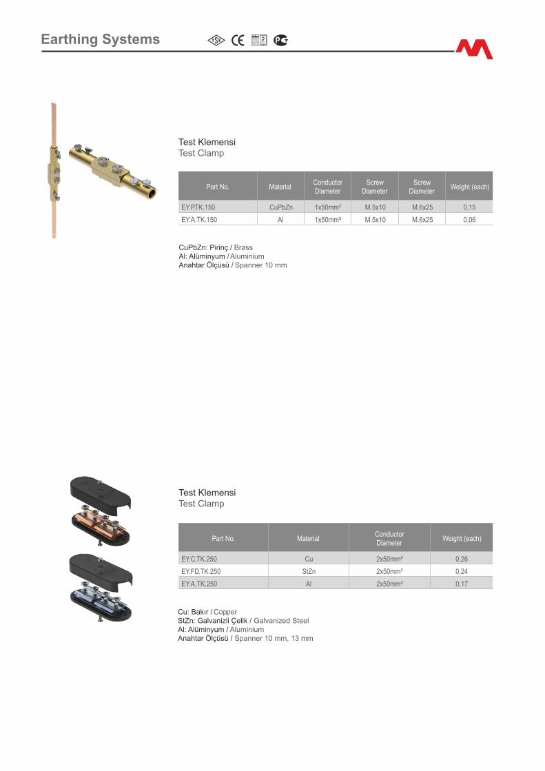
Earth�ng Systems
Test Klemens�Test Clamp
Part No. Mater�alConductorD�ameter
Screw D�ameter
Screw D�ameter
We�ght (each)
EY.P.TK.150 CuPbZn 1x50mm² M.5x10 M.6x25 0,15
EY.A.TK.150 Al 1x50mm² M.5x10 M.6x25 0,06
CuPbZn: P�r�nç / Brass Al: Alüm�nyum / Alum�n�umAnahtar Ölçüsü / Spanner 10 mm
Test Klemens�Test Clamp
Part No. Mater�alConductorD�ameter
We�ght (each)
EY.C.TK.250 Cu 2x50mm² 0,26
EY.FD.TK.250 StZn 2x50mm² 0,24
EY.A.TK.250 Al 2x50mm² 0,17
Cu: Bakır / CopperStZn: Galvan�zl� Çel�k / Galvan�zed Steel Al: Alüm�nyum / Alum�n�umAnahtar Ölçüsü / Spanner 10 mm, 13 mm
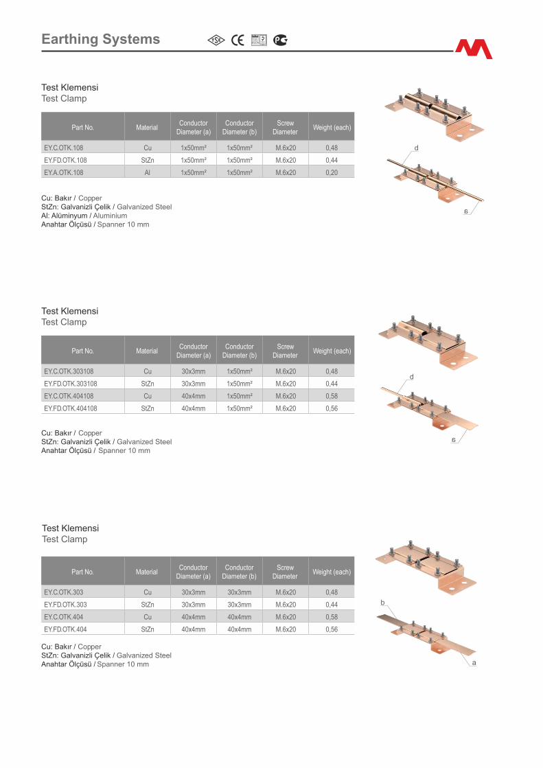
Earth�ng Systems
Part No. Mater�alConductor
D�ameter (a)Conductor
D�ameter (b)Screw
D�ameterWe�ght (each)
EY.C.OTK.108 Cu 1x50mm² 1x50mm² M.6x20 0,48
EY.FD.OTK.108 StZn 1x50mm² 1x50mm² M.6x20 0,44
EY.A.OTK.108 Al 1x50mm² 1x50mm² M.6x20 0,20
Test Klemens�Test Clamp
Cu: Bakır / CopperStZn: Galvan�zl� Çel�k / Galvan�zed Steel Al: Alüm�nyum / Alum�n�umAnahtar Ölçüsü / Spanner 10 mm
Part No. Mater�alConductor
D�ameter (a)Conductor
D�ameter (b)Screw
D�ameterWe�ght (each)
EY.C.OTK.303108 Cu 30x3mm 1x50mm² M.6x20 0,48
EY.FD.OTK.303108 StZn 30x3mm 1x50mm² M.6x20 0,44
EY.C.OTK.404108 Cu 40x4mm 1x50mm² M.6x20 0,58
EY.FD.OTK.404108 StZn 40x4mm 1x50mm² M.6x20 0,56
Test Klemens�Test Clamp
Cu: Bakır / Copper StZn: Galvan�zl� Çel�k / Galvan�zed Steel Anahtar Ölçüsü / Spanner 10 mm
a
a
b
b
Part No. Mater�alConductor
D�ameter (a)Conductor
D�ameter (b)Screw
D�ameterWe�ght (each)
EY.C.OTK.303 Cu 30x3mm 30x3mm M.6x20 0,48
EY.FD.OTK.303 StZn 30x3mm 30x3mm M.6x20 0,44
EY.C.OTK.404 Cu 40x4mm 40x4mm M.6x20 0,58
EY.FD.OTK.404 StZn 40x4mm 40x4mm M.6x20 0,56
Test Klemens�Test Clamp
Cu: Bakır / Copper StZn: Galvan�zl� Çel�k / Galvan�zed Steel Anahtar Ölçüsü / Spanner 10 mm a
b
Related Documents