Earth Resistance Calculation

Welcome message from author
This document is posted to help you gain knowledge. Please leave a comment to let me know what you think about it! Share it to your friends and learn new things together.
Transcript

Earth Resistance Calculation
Objective : *- The purpose of this project is to use a proper method for measuring the ground resistance with the help of Megger earth tester device.

What is grounding or earthing system ?
The purpose of earthing electrical equipment (providing a path for fault current to earth) is to protect the equipment and who in touch with it from the electrical shock and also from the fault currents
Although the earthing or grounding in electrical system is always invisible by physically & by its function but we can feel its importance only with the problems in electrical system with poor or no earthing system.
The term ground is defined as a conducting connection by which a circuit or equipment is connected to the earth
So , An earthing system or grounding system is circuitry which connects parts of the electric circuit with the ground
Purpose of grounding :
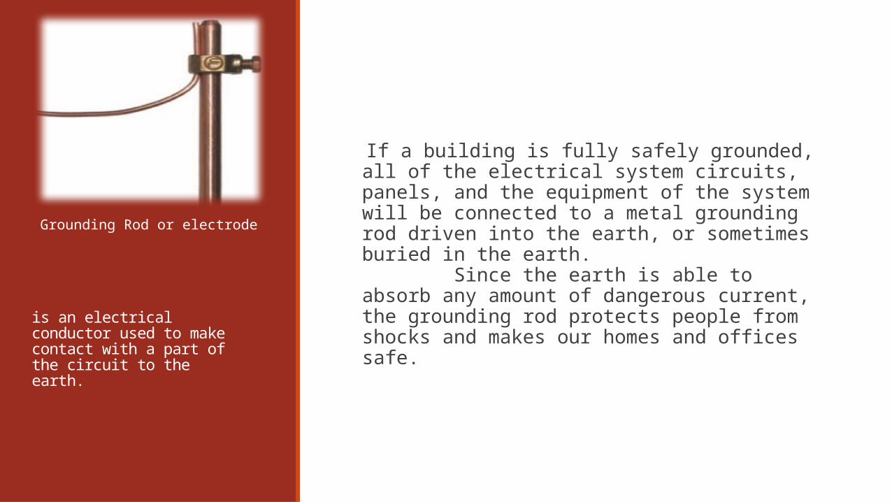
is an electrical conductor used to make contact with a part of the circuit to the earth.
If a building is fully safely grounded, all of the electrical system circuits, panels, and the equipment of the system will be connected to a metal grounding rod driven into the earth, or sometimes buried in the earth. Since the earth is able to absorb any amount of dangerous current, the grounding rod protects people from shocks and makes our homes and offices safe.
Grounding Rod or electrode
What is ground testing?Ground testing is the verification that resistance between the grounding system and earth
meet the purpose of providing a path for the fault current to flow so that it will
end danger and take rid of it through passing in this path to earth .
The path should have the minimum resistance as possible to ensure the most amount of current flow in it.

Earthing Values
Ideally electrical engineers should maintain ground resistance at zero ohms.
The ground resistance value may vary depending upon soil conditions, but basically for low voltage system it should be less than 1 ohm and for medium and high voltage system it should be in the range of 1 to 5 ohms.
Soil resistance values depend on soil composition, moisture, and temperature.
There are four basic variables which affect the resistance of the earth electrode:
1) The soil.
2) The length of the earth electrode.
3) The diameter of the earth electrode.
4) The depth in earth of the earth electrode.
Ground Resistance Measurements
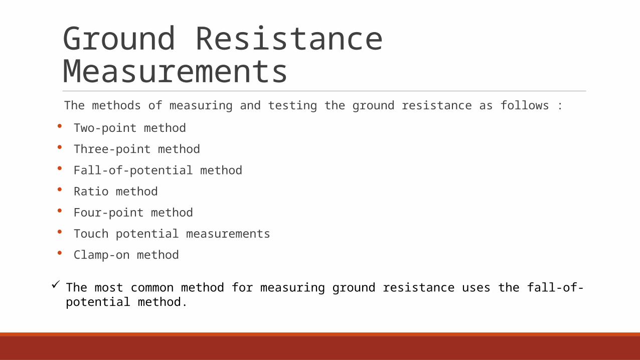
The methods of measuring and testing the ground resistance as follows :
Two-point method
Three-point method
Fall-of-potential method
Ratio method
Four-point method
Touch potential measurements
Clamp-on method
The most common method for measuring ground resistance uses the fall-of-potential method.

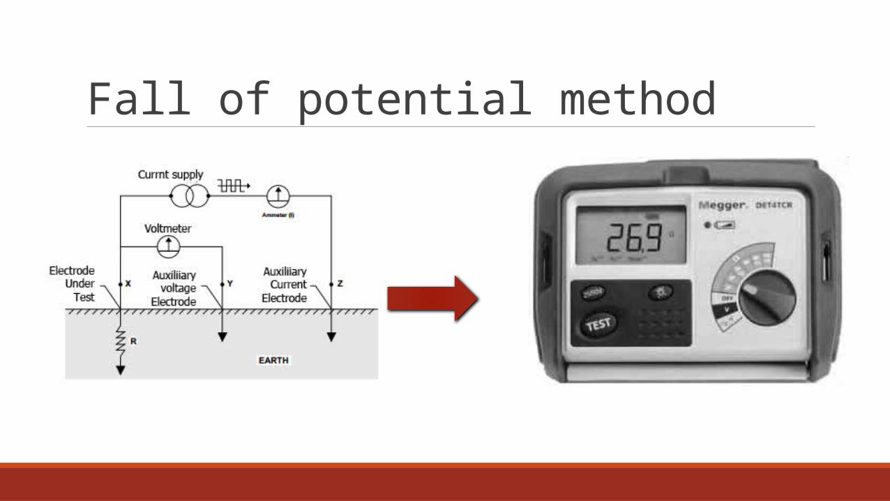
Fall of potential method :This method measures grounding electrode resistance based upon the principle of potential drop across the resistance.
It also uses two auxiliary electrodes (one current rod and the other a potential rod) that are placed at a sufficient distance from the test electrodes.
a current of known magnitude is passed through the electrode under test and one of the auxiliary electrodes (current rod).
The drop in potential between the electrode under the test and the second auxiliary electrode (potential rod) is measured.
The ratio of volt age drop (V) to the known current (I) will indicate the resistance of the grounding circuit. Either a DC or AC voltage source may be used for con ducting this test.
Fall of potential method

Effect of distance between the electrode under test and auxiliary electrode
(a) Low distance
(b) High distance

The readings of megger tester is not accurate because of the distance between the main electrode and current electrode is low (5m) such that the real value of electrode under test cannot be measured
Single electrode
It is found that under this condition ( i.e. the distance between electrode under test and auxiliary current electrode is 13 meter ) that this distance give the accurate value of resistance which is R=7.2Ω .
Practical results:

Multiple Ground
the readings was practical and less resistance value than the case of single electrode where at this condition we found that the resistance of the electrode under test is approximately equal to 5 Ω

Four electrodes in a straight line At the same depth and equally spacing between them

Electrodes under test Auxiliary voltage electrode
Auxiliary current electrode A reading


THANK YOU
Related Documents